US5839993A - Articulating stabilizer for a folding treadmill - Google Patents
Articulating stabilizer for a folding treadmillDownload PDFInfo
- Publication number
- US5839993A US5839993AUS08/889,671US88967197AUS5839993AUS 5839993 AUS5839993 AUS 5839993AUS 88967197 AUS88967197 AUS 88967197AUS 5839993 AUS5839993 AUS 5839993A
- Authority
- US
- United States
- Prior art keywords
- treadmill
- pivoting frame
- resisting
- stabilizer
- moment
- Prior art date
- Legal status (The legal status is an assumption and is not a legal conclusion. Google has not performed a legal analysis and makes no representation as to the accuracy of the status listed.)
- Expired - Fee Related
Links
- 239000003381stabilizerSubstances0.000titleclaimsdescription38
- 230000007246mechanismEffects0.000claimsabstractdescription47
- 230000005484gravityEffects0.000claimsabstractdescription13
- 230000013011matingEffects0.000claimsdescription9
- 230000008901benefitEffects0.000description5
- 230000006378damageEffects0.000description3
- 208000027418Wounds and injuryDiseases0.000description2
- 238000005452bendingMethods0.000description2
- 230000003247decreasing effectEffects0.000description2
- 238000001125extrusionMethods0.000description2
- 208000014674injuryDiseases0.000description2
- 230000009467reductionEffects0.000description2
- 230000008859changeEffects0.000description1
- 230000004048modificationEffects0.000description1
- 238000012986modificationMethods0.000description1
- 238000004806packaging method and processMethods0.000description1
- 238000006467substitution reactionMethods0.000description1
- 239000013598vectorSubstances0.000description1
Images

Classifications
- A—HUMAN NECESSITIES
- A63—SPORTS; GAMES; AMUSEMENTS
- A63B—APPARATUS FOR PHYSICAL TRAINING, GYMNASTICS, SWIMMING, CLIMBING, OR FENCING; BALL GAMES; TRAINING EQUIPMENT
- A63B22/00—Exercising apparatus specially adapted for conditioning the cardio-vascular system, for training agility or co-ordination of movements
- A63B22/02—Exercising apparatus specially adapted for conditioning the cardio-vascular system, for training agility or co-ordination of movements with movable endless bands, e.g. treadmills
- A—HUMAN NECESSITIES
- A63—SPORTS; GAMES; AMUSEMENTS
- A63B—APPARATUS FOR PHYSICAL TRAINING, GYMNASTICS, SWIMMING, CLIMBING, OR FENCING; BALL GAMES; TRAINING EQUIPMENT
- A63B2208/00—Characteristics or parameters related to the user or player
- A63B2208/12—Characteristics or parameters related to the user or player specially adapted for children
- A—HUMAN NECESSITIES
- A63—SPORTS; GAMES; AMUSEMENTS
- A63B—APPARATUS FOR PHYSICAL TRAINING, GYMNASTICS, SWIMMING, CLIMBING, OR FENCING; BALL GAMES; TRAINING EQUIPMENT
- A63B2210/00—Space saving
- A63B2210/50—Size reducing arrangements for stowing or transport
Definitions
- This inventionrelates to exercise equipment, and, more particularly, to treadmills which fold for storage.
- treadmillsto convey, on an endless track, a walking or running surface upon which the user may run or walk in place. Because treadmills must provide a surface which has a length which is greater than the stride of a user, and a width which exceeds the stance of the user, treadmills have historically required a significant amount of floor space for both operation and storage. Recently, however, the industry has produced a variety of treadmills in which the user may fold up the conveyor portion of the treadmill, including the supporting structure, into a vertical position for storage. This has substantially reduced the amount of floor space which the user must set aside for the treadmill when he or she is not using it.
- gas springsIn order to facilitate lowering of the conveyor portion of the treadmill, including the supporting structure, the industry generally uses gas springs to counteract the force of gravity.
- gas springsare linear devices, and, as such, they do not operate optimally when the moment arm length created between the axis of the gas spring and the pivot point vanes. The force vectors change as the pivoting frame lowers, thus varying the force with which the springs assist the user in lifting and lowering the pivoting frame. This results in an inconsistent lowering force which the user must resist. Such inconsistency can surprise the user, potentially causing him or her injury should he or she loose his grip on the treadmill.
- gas springshave a life expectancy of about two years--less than two years if stored in anything but a vertical position. Further, gas springs are complex, costly, and may present a pinch point hazard to the user, or to a small child.
- the folding or retracting operationmay impart bending, flexing, or tensile stresses to wiring which attaches between the two portions of a typical folding treadmill which rotate with respect to each other. This may cause damage to the wiring.
- a stabilizerwhich safely and automatically extends into position when the user places the treadmill in an operational position, and which automatically retracts when the user places the treadmill in a storage position.
- a mechanismwhich resists the force which gravity imparts on the conveyor portion, and which supports the structure with a constant torsional moment.
- a mechanismwhich provides a conduit through which wires can pass, such that lifting and lowering the conveyor will not subject the wires to tension, tangling, or bending, and which a technician can easily open for service.
- a treadmillwhich folds for storage.
- the treadmillincludes a main frame structure, a pivoting frame, a resisting mechanism, an articulating structure, and an articulating mechanism.
- the pivoting framepivotally mounts to the main frame structure along a main pivot axis such that a user may pivot the pivoting frame between a substantially vertical position and a substantially horizontal position.
- the pivoting framesupports a conveyor.
- the resisting mechanismapplies a torsional resisting moment to the pivoting frame.
- the resisting momentopposes a moment which gravity induces on the pivoting frame.
- the articulating mechanismUpon moving the pivoting frame between the vertical position to the horizontal position, the articulating mechanism automatically articulates the articulating structure between a stored, retracted position and an extended position in which the treadmill is stabilized.
- the articulating mechanismis a slider-crank mechanism.
- the articulating mechanismincludes a stabilizer which extends horizontally from a mating structure.
- the mating structureis fixed to the main frame structure.
- a rod or linkageconnects from an end of the stabilizer to a pivot on the pivoting frame.
- the pivothas an axis which is parallel to and not coaxial with the main pivot axis.
- the resisting mechanismincludes at least one torsion spring at the main pivot axis. An end of the torsion spring anchors to the main frame structure. Another end anchors to the pivoting frame.
- the torsion springmounts coaxially with respect to a hollow shaft.
- the hollow shaftis fixed to the main frame structure.
- the hollow shaftfunctions as both a pivot axle, on which the pivoting frame may pivot, and a conduit, through which wires may pass between the main frame structure and the pivoting frame.
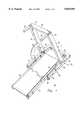
- FIG. 1is a perspective view of a preferred embodiment of the invention.
- FIG. 2Ais a partial break-away, side view of the preferred embodiment in a retracted position.
- FIG. 2Bis a partial break-away, side view of the preferred embodiment in an intermediate position.
- FIG. 2Cis a side view of the invention in an operational position.
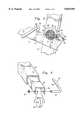
- FIG. 3is a close-up view of the region of FIG. 2B which reference numeral 3 indicates.
- FIG. 4is a perspective view of the stabilizer of the present invention.
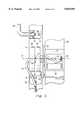
- FIG. 5is a partial, cross-sectional view taken along a plane which reference numeral 5 in FIG. 2C indicates.
- a treadmill 10which folds for storage.
- the treadmill 10includes a main frame structure 12, a pivoting frame 14, a resisting mechanism 16, a stabilizer or articulating structure 18, and an articulating mechanism 20.
- the main frame structure 12includes two upright portions 22 having lower ends 24 and upper ends 26.
- a cross member 28connects the upper ends 26 of the upright portions 22.
- Handles or grips 30attach to the upper ends 26, and provide support for a user (not shown) when the user operates the treadmill 10.
- the pivoting frame 14pivotally mounts to the main frame structure 12 along a main pivot axis 32, such that the user may pivot the pivoting frame 14 from a substantially vertical position (shown in FIG. 2A) to a substantially horizontal position (shown in FIG. 2C).
- the pivoting frame 14supports a conveyor 34 and related drive components 36.
- the resisting mechanism 16applies a torsional resisting moment 38 to the pivoting frame 14.
- the resisting moment 38opposes a moment induced by gravity on the pivoting frame 14 and is greater than or equal to the minimum torsional moment necessary to hold the pivoting frame up when in the stored position.
- the resisting mechanism 16includes at least one torsion, clock-type spring 40 at the main pivot axis 32. Ends 42 and 44 of the torsional spring 40 anchor between the main frame structure 12 and the pivoting frame 14, respectively.
- the torsion spring 40mounts coaxially with respect to a hollow shaft or axle 46.
- the hollow shaft 46is welded to the main frame structure 12.
- the hollow shaft 46has a key way 48 into which the end 42 of the torsion spring 40 inserts.
- the hollow shaft 46functions as both a pivot axle, on which the pivoting frame 14 may pivot, and as a conduit, through which wires 50 may pass between the main frame structure 12 and the pivoting frame 14.
- a bracket 52has a hole (not shown) through which the hollow shaft 46 passes and in which it pivots.
- the bracket 52has an end portion 54 which fastens to the pivoting frame 14.
- a hook 56fastens to the pivoting frame 14. The hook 56 anchors the end 44 of the torsional spring 40 to the pivoting frame 14.
- the articulating mechanism 20is a slider-crank mechanism.
- the articulating mechanism 20includes the stabilizer 18 which extends horizontally from a mating structure 58.
- the stabilizer 18is the slider of the slider-crank mechanism.
- the pivoting frame 14functions as the crank of the slider-crank mechanism.
- a linkage 60functions as the rod of the slider-crank mechanism.
- an end portion 62 of the linkage 60bends 90 degrees, thus functioning as an axle to a roller or wheel 66.
- a retainer 67retains the end portion 62 within the stabilizer 18.
- On an opposite end portion 68 of the linkage 60the linkage is pivotally received into a bracket 70.
- a retainer 72retains the end portion 68 in the bracket 70.
- the mating structure 58is fixed to the main frame structure 12.
- a major portion 64 of the linkage 60connects from the end portion 62 to the opposite end portion 68.
- the opposite end portion 68has a pivot axis which is parallel to and not coaxial with the main pivot axis 32.
- the roller 66mounts at an outboard end 74 of the stabilizer 18, thus minimizing friction during extension or retraction of the stabilizer.
- Plastic bushings 78mount between the stabilizer 18 and the mating structure 58 and extend several inches into the structure, further helping to minimize friction by increasing the bushings' length-to-width ratios.
- a latch 80pivotally mounts to the main frame structure 12 on pivot 86.
- a spring 88upwardly biases the latch 80.
- a pawl 82 on the latch 80engages a catch 84.
- the catch 84attaches to the pivoting frame 14.
- the latch 80locks the pivoting frame 14 to the main frame structure 12, thus preventing movement of the pivoting frame and enabling safe relocation of the treadmill 10.
- the userconveniently disengages the latch 80 by applying a force with his foot to a region 80a of the latch.
- wires 50run in an open channel 89 and through the hollow shaft 46 at the pivot axis 32.
- a plastic extrusion 90inserts into the channel 89, thus forming a closed conduit which hides the wires 50. Because all that a technician must do to access the wires 50 is remove the extrusion 90, the technician need not route, feed, and pull the wires through the main frame structure 12. In addition, because the wires 50 pass through the hollow shaft 46 at the pivot axis 32, flexing of the wires is minimized when lifting or lowering the pivoting frame 14.
- a technical advantage of the present inventionis that the stabilizer 18 improves safety by improving the stability of the treadmill 10 after the pivoting frame 14 is lowered for use. When the pivoting frame 14 is in a horizontal position, the stabilizer 18 fully extends. This maximizes the footing of the treadmill 10, and thus minimizes the likelihood that the treadmill will tip when the user applies a force to the handle 30.
- the treadmill 10folds into a small storage volume (or overall package size) when the user raises the pivoting frame 14 for storage, thus eliminating post purchase assembly or time-consuming disassembly when storing the device between uses, and saving valuable floor space.
- Another technical advantage of the inventionis that the stabilizer 18 automatically extends when a user lowers the pivoting frame 14, thus eliminating the danger that a negligent or forgetful user will fail to extend or install the stabilizer 18 when using the treadmill 10.
- the torsion spring 40minimizes lifting and lowering forces which the user must impart when re-positioning the pivoting frame 14.
- the torsion spring 40provides a constant torsional moment 38 which keeps the pivoting frame 14 in an up position whether or not the latch 80 is engaged.
- the hollow shaft 50may be welded to the main frame structure 12.
- the hollow shaftmay be welded to the pivoting frame 14.
- the hook 56would fasten to the main frame structure 12, instead of fastening to the pivoting frame 14.
- articulating mechanismsincluding a rack-and-pinion mechanism, a pulley and belt system (or a chain and sprocket system), a multi-bar linkage mechanism (including four-bar linkages), a semi-flexible ribbon and guide system in which the semi-flexible ribbon bends around a corner yet transmits compressive loads, or a combination of the mechanisms mentioned above. Accordingly, it is appropriate that the appended claims be construed broadly and consistent with the scope of the invention.
Landscapes
- Health & Medical Sciences (AREA)
- Cardiology (AREA)
- Vascular Medicine (AREA)
- General Health & Medical Sciences (AREA)
- Physical Education & Sports Medicine (AREA)
- Rehabilitation Tools (AREA)
Abstract
Description
Claims (23)
Priority Applications (1)
| Application Number | Priority Date | Filing Date | Title |
|---|---|---|---|
| US08/889,671US5839993A (en) | 1997-07-08 | 1997-07-08 | Articulating stabilizer for a folding treadmill |
Applications Claiming Priority (1)
| Application Number | Priority Date | Filing Date | Title |
|---|---|---|---|
| US08/889,671US5839993A (en) | 1997-07-08 | 1997-07-08 | Articulating stabilizer for a folding treadmill |
Publications (1)
| Publication Number | Publication Date |
|---|---|
| US5839993Atrue US5839993A (en) | 1998-11-24 |
Family
ID=25395567
Family Applications (1)
| Application Number | Title | Priority Date | Filing Date |
|---|---|---|---|
| US08/889,671Expired - Fee RelatedUS5839993A (en) | 1997-07-08 | 1997-07-08 | Articulating stabilizer for a folding treadmill |
Country Status (1)
| Country | Link |
|---|---|
| US (1) | US5839993A (en) |
Cited By (31)
| Publication number | Priority date | Publication date | Assignee | Title |
|---|---|---|---|---|
| US6261209B1 (en)* | 1998-05-29 | 2001-07-17 | Fitness Quest, Inc. | Folding exercise treadmill with front inclination |
| US20060040798A1 (en)* | 2004-08-17 | 2006-02-23 | Nautilus, Inc. | Treadmill deck locking mechanism |
| US7455626B2 (en)* | 2001-12-31 | 2008-11-25 | Nautilus, Inc. | Treadmill |
| US20150087483A1 (en)* | 2013-09-25 | 2015-03-26 | Dyaco International Inc. | Foldable Treadmill |
| US20170274248A1 (en)* | 2014-08-25 | 2017-09-28 | The Uab Research Foundation | System and method for performing exercise testing and training |
| US10188890B2 (en) | 2013-12-26 | 2019-01-29 | Icon Health & Fitness, Inc. | Magnetic resistance mechanism in a cable machine |
| US10252109B2 (en) | 2016-05-13 | 2019-04-09 | Icon Health & Fitness, Inc. | Weight platform treadmill |
| US10258828B2 (en) | 2015-01-16 | 2019-04-16 | Icon Health & Fitness, Inc. | Controls for an exercise device |
| US10272317B2 (en) | 2016-03-18 | 2019-04-30 | Icon Health & Fitness, Inc. | Lighted pace feature in a treadmill |
| US10279212B2 (en) | 2013-03-14 | 2019-05-07 | Icon Health & Fitness, Inc. | Strength training apparatus with flywheel and related methods |
| US10293211B2 (en) | 2016-03-18 | 2019-05-21 | Icon Health & Fitness, Inc. | Coordinated weight selection |
| US10335632B2 (en)* | 2015-12-31 | 2019-07-02 | Nautilus, Inc. | Treadmill including a deck locking mechanism |
| US10343017B2 (en) | 2016-11-01 | 2019-07-09 | Icon Health & Fitness, Inc. | Distance sensor for console positioning |
| US10376736B2 (en) | 2016-10-12 | 2019-08-13 | Icon Health & Fitness, Inc. | Cooling an exercise device during a dive motor runway condition |
| US10426989B2 (en) | 2014-06-09 | 2019-10-01 | Icon Health & Fitness, Inc. | Cable system incorporated into a treadmill |
| US10433612B2 (en) | 2014-03-10 | 2019-10-08 | Icon Health & Fitness, Inc. | Pressure sensor to quantify work |
| US10441844B2 (en) | 2016-07-01 | 2019-10-15 | Icon Health & Fitness, Inc. | Cooling systems and methods for exercise equipment |
| US10471299B2 (en) | 2016-07-01 | 2019-11-12 | Icon Health & Fitness, Inc. | Systems and methods for cooling internal exercise equipment components |
| US10493349B2 (en) | 2016-03-18 | 2019-12-03 | Icon Health & Fitness, Inc. | Display on exercise device |
| US10500473B2 (en) | 2016-10-10 | 2019-12-10 | Icon Health & Fitness, Inc. | Console positioning |
| US10543395B2 (en) | 2016-12-05 | 2020-01-28 | Icon Health & Fitness, Inc. | Offsetting treadmill deck weight during operation |
| US10561894B2 (en) | 2016-03-18 | 2020-02-18 | Icon Health & Fitness, Inc. | Treadmill with removable supports |
| US10625137B2 (en) | 2016-03-18 | 2020-04-21 | Icon Health & Fitness, Inc. | Coordinated displays in an exercise device |
| US10661114B2 (en) | 2016-11-01 | 2020-05-26 | Icon Health & Fitness, Inc. | Body weight lift mechanism on treadmill |
| US10729965B2 (en) | 2017-12-22 | 2020-08-04 | Icon Health & Fitness, Inc. | Audible belt guide in a treadmill |
| US10953305B2 (en) | 2015-08-26 | 2021-03-23 | Icon Health & Fitness, Inc. | Strength exercise mechanisms |
| US11451108B2 (en) | 2017-08-16 | 2022-09-20 | Ifit Inc. | Systems and methods for axial impact resistance in electric motors |
| US20220331650A1 (en)* | 2022-05-19 | 2022-10-20 | Yongkang Saihan Electronic Technology Co.,Ltd. | Vertical-column folding mechanism and foldable treadmill |
| US20230014949A1 (en)* | 2021-07-16 | 2023-01-19 | Beijing Xiaomi Mobile Software Co., Ltd. | Foldable treadmill |
| US20230358069A1 (en)* | 2022-05-05 | 2023-11-09 | Wilbur L. Anderson, Inc. | Tilt Tower and Method of Assembly. |
| USD1057051S1 (en)* | 2021-03-25 | 2025-01-07 | Beijing Kingsmith Technology Co., Ltd | Treadmill |
Citations (10)
| Publication number | Priority date | Publication date | Assignee | Title |
|---|---|---|---|---|
| US931394A (en)* | 1909-04-28 | 1909-08-17 | Alfred Day | Exercising device. |
| US2117957A (en)* | 1937-03-05 | 1938-05-17 | Harry C Ritter | Exercising device |
| US3731917A (en)* | 1971-02-25 | 1973-05-08 | Townsend Engineering Co | Treadmill exercising device |
| US4026545A (en)* | 1975-11-25 | 1977-05-31 | Schoenenberger Rolf | Physical exercise apparatus |
| US4066257A (en)* | 1975-11-07 | 1978-01-03 | Moller Bynum W | Treadmill exercising device |
| US4625962A (en)* | 1984-10-22 | 1986-12-02 | The Cleveland Clinic Foundation | Upper body exercise apparatus |
| US4664646A (en)* | 1985-01-25 | 1987-05-12 | Rorabaugh Barre L | Treadmill motor drive |
| US4974831A (en)* | 1990-01-10 | 1990-12-04 | Precor Incorporated | Exercise treadmill |
| US5676624A (en)* | 1996-01-30 | 1997-10-14 | Icon Health & Fitness, Inc. | Portable reorienting treadmill |
| US5772560A (en)* | 1996-01-30 | 1998-06-30 | Icon Health & Fitness, Inc. | Reorienting treadmill with lift assistance |
- 1997
- 1997-07-08USUS08/889,671patent/US5839993A/ennot_activeExpired - Fee Related
Patent Citations (10)
| Publication number | Priority date | Publication date | Assignee | Title |
|---|---|---|---|---|
| US931394A (en)* | 1909-04-28 | 1909-08-17 | Alfred Day | Exercising device. |
| US2117957A (en)* | 1937-03-05 | 1938-05-17 | Harry C Ritter | Exercising device |
| US3731917A (en)* | 1971-02-25 | 1973-05-08 | Townsend Engineering Co | Treadmill exercising device |
| US4066257A (en)* | 1975-11-07 | 1978-01-03 | Moller Bynum W | Treadmill exercising device |
| US4026545A (en)* | 1975-11-25 | 1977-05-31 | Schoenenberger Rolf | Physical exercise apparatus |
| US4625962A (en)* | 1984-10-22 | 1986-12-02 | The Cleveland Clinic Foundation | Upper body exercise apparatus |
| US4664646A (en)* | 1985-01-25 | 1987-05-12 | Rorabaugh Barre L | Treadmill motor drive |
| US4974831A (en)* | 1990-01-10 | 1990-12-04 | Precor Incorporated | Exercise treadmill |
| US5676624A (en)* | 1996-01-30 | 1997-10-14 | Icon Health & Fitness, Inc. | Portable reorienting treadmill |
| US5772560A (en)* | 1996-01-30 | 1998-06-30 | Icon Health & Fitness, Inc. | Reorienting treadmill with lift assistance |
Non-Patent Citations (5)
| Title |
|---|
| Brochure, "Taiwan Sports Goods Buyers' Guide '95," Tradewinds, 1995, Cover page plus pp. 20,21,197,317 and 327. |
| Brochure, "Technology for Total Fitness," Genesis 2000, 1985. |
| Brochure, Taiwan Sports Goods Buyers Guide 95, Tradewinds, 1995, Cover page plus pp. 20,21,197,317 and 327.* |
| Brochure, Technology for Total Fitness, Genesis 2000, 1985.* |
| Genesis 4000 brochure, copyright Genesis, Inc. 1985.* |
Cited By (42)
| Publication number | Priority date | Publication date | Assignee | Title |
|---|---|---|---|---|
| US6261209B1 (en)* | 1998-05-29 | 2001-07-17 | Fitness Quest, Inc. | Folding exercise treadmill with front inclination |
| US7854690B2 (en) | 2001-12-31 | 2010-12-21 | Nautilus, Inc. | Treadmill |
| US7455626B2 (en)* | 2001-12-31 | 2008-11-25 | Nautilus, Inc. | Treadmill |
| US7544153B2 (en)* | 2001-12-31 | 2009-06-09 | Nautilus, Inc. | Treadmill |
| US20090312158A1 (en)* | 2001-12-31 | 2009-12-17 | Nautilus, Inc. | Treadmill |
| US7736280B2 (en)* | 2004-08-17 | 2010-06-15 | Nautilus, Inc. | Treadmill deck locking mechanism |
| US20060040798A1 (en)* | 2004-08-17 | 2006-02-23 | Nautilus, Inc. | Treadmill deck locking mechanism |
| US7914421B2 (en) | 2004-08-17 | 2011-03-29 | Nautilus, Inc. | Treadmill deck locking mechanism |
| US20100248904A1 (en)* | 2004-08-17 | 2010-09-30 | Nautilus, Inc. | Treadmill deck locking mechanism |
| US10279212B2 (en) | 2013-03-14 | 2019-05-07 | Icon Health & Fitness, Inc. | Strength training apparatus with flywheel and related methods |
| US20150087483A1 (en)* | 2013-09-25 | 2015-03-26 | Dyaco International Inc. | Foldable Treadmill |
| US9168415B2 (en)* | 2013-09-25 | 2015-10-27 | Dyaco International Inc. | Foldable treadmill |
| US10188890B2 (en) | 2013-12-26 | 2019-01-29 | Icon Health & Fitness, Inc. | Magnetic resistance mechanism in a cable machine |
| US10433612B2 (en) | 2014-03-10 | 2019-10-08 | Icon Health & Fitness, Inc. | Pressure sensor to quantify work |
| US10426989B2 (en) | 2014-06-09 | 2019-10-01 | Icon Health & Fitness, Inc. | Cable system incorporated into a treadmill |
| US20170274248A1 (en)* | 2014-08-25 | 2017-09-28 | The Uab Research Foundation | System and method for performing exercise testing and training |
| US10456624B2 (en)* | 2014-08-25 | 2019-10-29 | The Uab Research Foundation | System and method for performing exercise testing and training |
| US10258828B2 (en) | 2015-01-16 | 2019-04-16 | Icon Health & Fitness, Inc. | Controls for an exercise device |
| US10953305B2 (en) | 2015-08-26 | 2021-03-23 | Icon Health & Fitness, Inc. | Strength exercise mechanisms |
| US10335632B2 (en)* | 2015-12-31 | 2019-07-02 | Nautilus, Inc. | Treadmill including a deck locking mechanism |
| US10625137B2 (en) | 2016-03-18 | 2020-04-21 | Icon Health & Fitness, Inc. | Coordinated displays in an exercise device |
| US10272317B2 (en) | 2016-03-18 | 2019-04-30 | Icon Health & Fitness, Inc. | Lighted pace feature in a treadmill |
| US10293211B2 (en) | 2016-03-18 | 2019-05-21 | Icon Health & Fitness, Inc. | Coordinated weight selection |
| US10493349B2 (en) | 2016-03-18 | 2019-12-03 | Icon Health & Fitness, Inc. | Display on exercise device |
| US10561894B2 (en) | 2016-03-18 | 2020-02-18 | Icon Health & Fitness, Inc. | Treadmill with removable supports |
| US10252109B2 (en) | 2016-05-13 | 2019-04-09 | Icon Health & Fitness, Inc. | Weight platform treadmill |
| US10441844B2 (en) | 2016-07-01 | 2019-10-15 | Icon Health & Fitness, Inc. | Cooling systems and methods for exercise equipment |
| US10471299B2 (en) | 2016-07-01 | 2019-11-12 | Icon Health & Fitness, Inc. | Systems and methods for cooling internal exercise equipment components |
| US10500473B2 (en) | 2016-10-10 | 2019-12-10 | Icon Health & Fitness, Inc. | Console positioning |
| US10376736B2 (en) | 2016-10-12 | 2019-08-13 | Icon Health & Fitness, Inc. | Cooling an exercise device during a dive motor runway condition |
| US10661114B2 (en) | 2016-11-01 | 2020-05-26 | Icon Health & Fitness, Inc. | Body weight lift mechanism on treadmill |
| US10343017B2 (en) | 2016-11-01 | 2019-07-09 | Icon Health & Fitness, Inc. | Distance sensor for console positioning |
| US10543395B2 (en) | 2016-12-05 | 2020-01-28 | Icon Health & Fitness, Inc. | Offsetting treadmill deck weight during operation |
| US11451108B2 (en) | 2017-08-16 | 2022-09-20 | Ifit Inc. | Systems and methods for axial impact resistance in electric motors |
| US10729965B2 (en) | 2017-12-22 | 2020-08-04 | Icon Health & Fitness, Inc. | Audible belt guide in a treadmill |
| USD1057051S1 (en)* | 2021-03-25 | 2025-01-07 | Beijing Kingsmith Technology Co., Ltd | Treadmill |
| US20230014949A1 (en)* | 2021-07-16 | 2023-01-19 | Beijing Xiaomi Mobile Software Co., Ltd. | Foldable treadmill |
| US11779800B2 (en)* | 2021-07-16 | 2023-10-10 | Beijing Xiaomi Mobile Software Co., Ltd. | Foldable treadmill |
| US20230358069A1 (en)* | 2022-05-05 | 2023-11-09 | Wilbur L. Anderson, Inc. | Tilt Tower and Method of Assembly. |
| US20240125139A1 (en)* | 2022-05-05 | 2024-04-18 | Wilbur L. Anderson, Inc. | Tilt Tower and Method of Assembly |
| US20220331650A1 (en)* | 2022-05-19 | 2022-10-20 | Yongkang Saihan Electronic Technology Co.,Ltd. | Vertical-column folding mechanism and foldable treadmill |
| US12102869B2 (en)* | 2022-05-19 | 2024-10-01 | Yongkang Saihan Blectronic Technology Co Ltd. | Vertical-column folding mechanism and foldable treadmill |
Similar Documents
| Publication | Publication Date | Title |
|---|---|---|
| US5839993A (en) | Articulating stabilizer for a folding treadmill | |
| JP4047726B2 (en) | Exercise equipment | |
| US5830113A (en) | Foldable treadmill and bench apparatus and method | |
| US5868648A (en) | Foldable treadmill apparatus and method | |
| US6261209B1 (en) | Folding exercise treadmill with front inclination | |
| US8834332B2 (en) | Collapsible inclinable exercise device and method of using same | |
| US6116378A (en) | Universal, compact, truck tailgate ladder with support arms | |
| US7775940B2 (en) | Folding elliptical exercise machine | |
| US7614989B1 (en) | Bend and stretch abdominal and lower back exercise machine | |
| US9744399B2 (en) | Exercise machine | |
| AU2002254562A1 (en) | Collapsible reformer exercise apparatus | |
| JP2019516603A (en) | Tarpaulin structure | |
| CA2351296C (en) | Tree stand | |
| US6857679B2 (en) | Method and apparatus for assisting in the lowering and raising of a tailgate | |
| AU758446B2 (en) | Overhead supported net system | |
| US20060054398A1 (en) | Ladder stabilizer | |
| US20040167000A1 (en) | Leg exercise method and apparatus | |
| US6874798B2 (en) | Golf bag cart | |
| US11707059B2 (en) | Tree stand and method of use thereof | |
| EP2346581B1 (en) | Exercise apparatus | |
| CN107461144A (en) | Ladder support device and the method for ladder to be fastened to base | |
| CA2464493C (en) | Method and apparatus for assisting in the lowering and raising of a tailgate | |
| US20090140539A1 (en) | Rear Bag Cover and Method of Attachment By Brackets | |
| US20240157215A1 (en) | Basketball rebounding apparatus | |
| KR200234297Y1 (en) | golf bag |
Legal Events
| Date | Code | Title | Description |
|---|---|---|---|
| AS | Assignment | Owner name:KEYS FITNESS PRODUCTS, INC., TEXAS Free format text:ASSIGNMENT OF ASSIGNORS INTEREST;ASSIGNOR:FOX, GARY TOM;REEL/FRAME:008686/0899 Effective date:19970703 | |
| FPAY | Fee payment | Year of fee payment:4 | |
| FPAY | Fee payment | Year of fee payment:8 | |
| AS | Assignment | Owner name:KEYS FITNESS PRODUCTS, INC., A DELAWARE CORPORATIO Free format text:MERGER;ASSIGNOR:KEYS FITNESS PRODUCTS, INC., A TEXAS CORPORATION;REEL/FRAME:020317/0330 Effective date:19961230 | |
| AS | Assignment | Owner name:KEYS FITNESS PRODUCTS, LP, A TEXAS LIMITED PARTNER Free format text:ASSIGNMENT OF ASSIGNORS INTEREST;ASSIGNOR:KEYS FITNESS PRODUCTS, INC., A DELAWARE CORPORATION;REEL/FRAME:020327/0688 Effective date:20080104 | |
| AS | Assignment | Owner name:JP KFP ACQUISITION, LLC, NEW YORK Free format text:SECURITY AGREEMENT;ASSIGNOR:KEYS FITNESS PRODUCTS, LP, A TEXAS LIMITED PARTNERSHIP;REEL/FRAME:020343/0824 Effective date:20080104 | |
| REMI | Maintenance fee reminder mailed | ||
| LAPS | Lapse for failure to pay maintenance fees | ||
| LAPS | Lapse for failure to pay maintenance fees | Free format text:PATENT EXPIRED FOR FAILURE TO PAY MAINTENANCE FEES (ORIGINAL EVENT CODE: EXP.); ENTITY STATUS OF PATENT OWNER: SMALL ENTITY | |
| STCH | Information on status: patent discontinuation | Free format text:PATENT EXPIRED DUE TO NONPAYMENT OF MAINTENANCE FEES UNDER 37 CFR 1.362 | |
| FP | Lapsed due to failure to pay maintenance fee | Effective date:20101124 |