US5839686A - Chain driven pretensioner and retractor - Google Patents
Chain driven pretensioner and retractorDownload PDFInfo
- Publication number
- US5839686A US5839686AUS08/542,370US54237095AUS5839686AUS 5839686 AUS5839686 AUS 5839686AUS 54237095 AUS54237095 AUS 54237095AUS 5839686 AUS5839686 AUS 5839686A
- Authority
- US
- United States
- Prior art keywords
- gear
- spool
- chain
- retractor
- drive
- Prior art date
- Legal status (The legal status is an assumption and is not a legal conclusion. Google has not performed a legal analysis and makes no representation as to the accuracy of the status listed.)
- Expired - Fee Related
Links
Images


Classifications
- B—PERFORMING OPERATIONS; TRANSPORTING
- B60—VEHICLES IN GENERAL
- B60R—VEHICLES, VEHICLE FITTINGS, OR VEHICLE PARTS, NOT OTHERWISE PROVIDED FOR
- B60R22/00—Safety belts or body harnesses in vehicles
- B60R22/34—Belt retractors, e.g. reels
- B60R22/46—Reels with means to tension the belt in an emergency by forced winding up
- B60R22/4628—Reels with means to tension the belt in an emergency by forced winding up characterised by fluid actuators, e.g. pyrotechnic gas generators
- B—PERFORMING OPERATIONS; TRANSPORTING
- B60—VEHICLES IN GENERAL
- B60R—VEHICLES, VEHICLE FITTINGS, OR VEHICLE PARTS, NOT OTHERWISE PROVIDED FOR
- B60R22/00—Safety belts or body harnesses in vehicles
- B60R22/34—Belt retractors, e.g. reels
- B60R22/46—Reels with means to tension the belt in an emergency by forced winding up
- B60R22/4676—Reels with means to tension the belt in an emergency by forced winding up comprising energy-absorbing means operating between belt reel and retractor frame
- B—PERFORMING OPERATIONS; TRANSPORTING
- B60—VEHICLES IN GENERAL
- B60R—VEHICLES, VEHICLE FITTINGS, OR VEHICLE PARTS, NOT OTHERWISE PROVIDED FOR
- B60R22/00—Safety belts or body harnesses in vehicles
- B60R22/34—Belt retractors, e.g. reels
- B60R22/46—Reels with means to tension the belt in an emergency by forced winding up
- B60R22/4628—Reels with means to tension the belt in an emergency by forced winding up characterised by fluid actuators, e.g. pyrotechnic gas generators
- B60R2022/4642—Reels with means to tension the belt in an emergency by forced winding up characterised by fluid actuators, e.g. pyrotechnic gas generators the gas directly propelling a flexible driving means, e.g. a plurality of successive masses, in a tubular chamber
- B60R2022/4647—Reels with means to tension the belt in an emergency by forced winding up characterised by fluid actuators, e.g. pyrotechnic gas generators the gas directly propelling a flexible driving means, e.g. a plurality of successive masses, in a tubular chamber the driving means being a belt, a chain or the like
Definitions
- the present inventiongenerally relates to a safety restraint device for protecting vehicle occupants and more particularly a pretensioning device typically used to tension a seat belt wound about a seat belt retractor or attached to that portion of the seat belt connected to a buckle.
- Pretensioners or belt tightenersare currently used in industry to operate in conjunction with seat belt retractors or are attached to one end of the belt that is connected to a seat belt buckle.
- a typical pretensioner for a seat belt retractor or bucklecomprises a movable piston joined to a cable. The piston typically moves down a straight tube. The use of the straight tube creates packaging problems within the vehicle as it is difficult to orient the tube within the room that is made available.
- Retractor pretensionersalso use clutches to decouple the pretensioner from the retractor so that the pretensioner does not interfere with the normal operation of the retractor. These clutches are bulky and further increase the package size of the restraint device. The clutches are often intricate devices which complicate the operation of the pretensioner and add to its cost.
- the present inventioncomprises a first driven means operatively linked to a spool of a retractor to selectively rotate the spool in a direction of retraction to cause a seat belt wound thereabout to retract; a flexible first drive means having a front end initially maintained out of engagement with the first driven means and pushed into engagement with the first driven means to cause the first driven means to rotate; a second drive means operatively linked to a rear end of the first drive means for pushing the second drive means into engagement with the first driven means thereby causing the first drive means to rotate.
- the first driven meanscomprises a toothed gear
- the flexible drive meanscomprises a length of chain such as bicycle chain or plastic toothed chain or track
- the second driven meanscomprises a pyrotechnic element such as a detonator, initiator or squib which generates products of combustion within a pressure chamber against a piston linked to the flexible drive means.
- the toothed gearis connected to the retractor spool to reverse rotate the spool during an emergency as it is moved by the flexible drive means.
- the retractorincludes various sensors to initiate the locking up of the retractor during an accident to prevent protraction of the seat belt.
- the preferred embodiment of the inventiondiscloses a constant force retractor, that is, one that creates a controlled, limited force of the seat belt during emergency operation, however, virtually any retractor will operate with the pretensioner.
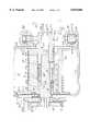
- FIG. 1illustrates a cross-sectional view illustrating the major components of the present invention.
- FIG. 3shows an alternate embodiment of the invention.
- the frameincludes frame sides 23a,b having respective openings 25a and 25b and a rear or connecting part 23c typically having an opening for receipt of a fastening bolt.
- the central openingsmay be of different diameter as shown or the same which will depend upon how the spool is supported on the frame sides.
- the retractoradditionally includes a spool or reel 24 rotatably mounted to the frame 22.
- the spoolincludes two (2) flanges 26a and 26b, a center part 27 about which seat belt webbing 31 is wound (two layers of webbing are shown in dotted line) and a center bore 28 which includes a plurality of axially directed splines, slots or key ways 30.
- the center part 27includes a slot 29 which provides a means for inserting one end of the seat belt 31 into the spool in a known manner.
- an axle assembly 50which includes a first member 52 inserted in bore end 28a, and a second member 70.
- the first member 52includes a walled portion 53 and provides a bushing surface to rotatably support the spool.
- the first member 52also includes a hexagonal bore 54 to provide a driving, rotational engagement with a complementary shaped end 55 of the second member 70 of the axle assembly.
- the first member 52includes a forked end 56 that forms a spring arbor and is adapted to receive a rewind spring 57, of known construction to retract the extended seat belt.
- Integrally formed on the first member 52is a gear, 402 which is part of the pretensioner 400.
- the inside surface of the nutincludes threads 94 which matingly engage threads 80 of the narrow portion 78.
- This nuton its outer surface, includes a plurality of splines 92 which permit the nut to move axially along the cooperating splines 30 of the spool 24 as it rotates on the threads 80.
- the threadscan be on the spool and the splines on the narrow portion 78.
- the second member 70also includes a lock wheel 71 that may be integrally formed or separate having lock teeth 73 thereon engaged by a locking pawl 77 rotatably mounted to the frame 22 in a known manner.
- a deformable, energy absorbing bushing 100 and a thrust washer 102Situated between the nut 90 and the stop member 79 is a deformable, energy absorbing bushing 100 and a thrust washer 102. There is a clearance fit between the washer 102 and the spool bore 28 and a slidable engagement with the outer diameter of the second member 70.
- the purpose of the thrust washeris to eliminate any torsional loading between the nut and the bushing 100 and permit the nut to be free to rotate relative to the washer 102.
- the primary reason for eliminating or at least minimizing the torsional loading between the nut and the washer 102is to better control the mode of deformation of the crushable member or bushing 100.
- a roll formed bushinghas been used or one that was lightly sand blasted.
- a surface roughness of greater than 32 micronsshould provide the proper amount of roughness to insure the desired bushing deformation characteristic.
- a bushing that is initially barrel shapedthat is, its diameter is larger near its middle than at its ends.
- One such barrel-like bushingis shown in phantom line 100'.
- the bushing 100'can be a pre-form shaped by hydro-form or roll forming processes.
- the retractoradditionally includes a web sensor 300 and a vehicle sensor 302.
- Member 70that is the lock wheel 71, is locked in response to information derived from the vehicle sensor and a web sensor. These sensors respectively sense excessive vehicle deceleration and an excessive rate increase of seat belt protraction from the retractor 20.
- One such vehicle sensor 302 and web sensor 300are diagrammatically shown in FIG. 1.
- the web sensormay be nestled within a lock cup 304 which is received adjacent a ratchet wheel 75.
- the vehicle sensoris carried by the lock cup and includes a sensor pawl that engages ratchet teeth 83. Movement of the lock cup moves the lock pawl 77 into engagement with the lock teeth 73.
- European Patent Document EP 0 228 729 A1is illustrative of a retractor having a web sensor, vehicle sensor, and lock cup to move the lock pawl 77 into engagement with the a lock wheel. This document is incorporated herein by reference.
- the rear end 416 of the tubeis flared to permit a detonator, squib, or initiator 420 to be secured therein.
- the detonator, initiator or squib 420is known in the art and produces products of combustion within a combustion chamber 422 upon receipt of an electric control signal generated by an electronic control unit 424 and communicated to the squib via wires 426.
- the control or activation signalis generated upon sensing that the vehicle is involved in an accident of sufficient magnitude to warrant added occupant protection.
- a driving mechanismSituated within the tube 408 is a driving mechanism generally shown as 430. In the illustrated embodiment this driving mechanism constitutes a flexible, toothed or linked member including bicycle chain 432 having a plurality of links 434a-434n.
- each the teeth 404includes a pointed tip 450. Extending down from the tip is an engagement surface generally shown as 452.
- the engagement surfaceincludes a flat portion 454 and a curved portion 456.
- the radius of curvature of the curved portionis preferably equal to the radius of each chain cross-bar 436.
- the rear surface 458 of each tooth 404is also generally flat.
- each cross-baris cylindrically shaped to engage with the engagement surface of a corresponding tooth.
- the first cross-bar 436ais a half-cylinder with a flat bottom.
- the purpose of this shapeis to provide for the synchronous engagement of the cross-bars 436 with the teeth 404 and also to prevent a cross-bar to tooth tip jammed condition.
- a circular, cylindrical first cross-barmight engage the tip of a tooth and jam.
- the first cross-barwill pass over a tooth that is in an angular position that would otherwise induce jamming and engage the next tooth, for example tooth 404a.
- the engagement of the first cross-bar with a toothnow insures the proper synchronous engagement of the other cross-bars and teeth.
- the operation of the system of the retractor 20 and pretensioner 400is as follows. Upon sensing an emergency condition the detonator 420 is activated to produce products of combustion which bear against a facing wall of the piston 440. The seal 442 of the piston prevents the products of combustion from escaping from the chamber 422. Thereafter the piston 440 is propelled down the passage 402 and in so doing pushes the chain down the passage. The chain is guided primarily by the guide walls 414. As each link 434a-434n moves past a driven gear 402, the teeth 404 are engaged by a corresponding one of the plurality of bars 436. As the driven gear 402 is driven by the driving device 430, i.e.
- the spool 24is reverse rotated so as to retract a determinable amount of webbing back onto the spool to draw the seat belt 31 tightly about the occupant. As shown, under the operation of the pretensioner 400 and with a full stroke of the chain, the spool 24 will reverse rotate about 2.5 revolutions.
- the tube 408As the chain 432 advances through the passage 400 its end 435 is pushed through the open end 410.
- the shape of the tube 408has not been discussed in any detail.
- the tubeis planar and arcuately shaped such that the ends 410 and 416 are proximate to one another providing a compact configuration.
- the tubecan be oval, square or rectangular with rounded corners, circular, straight, etc.
- the tubeIn the vicinity of the gear 402 the tube is bent slightly such as by about nineteen (19) degrees to insure that at least two (2) gear teeth 404 are in engagement with two cross-bars 436 at any given time.
- the lock wheelis stopped by the action of the various sensors and the pretensioner 400 is activated to reverse wind the spool.
- the rotation of the first member 52is transferred to the second member 70 through the interface of the bore 54 and end 55.
- the rotation of the second member 70is transferred to the spool 24 through the threaded and splined interconnection of the second member/nut/spool to eliminate slack in the seat belt (shoulder and/or lap belt).
- the pawl 77engaging the teeth 73 of the lock wheel 71 the second member 70 cannot rotate in a belt unwinding direction. Subsequently, the occupant will tend to move forward as the accident progresses and load the seat belt 31.
- the occupant's motion(position and acceleration) is then controlled by the reaction force generated within the retractor.
- the occupant's load on the shoulder beltis partially transmitted via the remaining seat belt webbing wound about the center part 27 of the spool 24 creating a torque tending to rotate the spool, in a belt unwinding direction.
- the spoolrotates about the bearing surfaces provided by the first member 52 and the member 79. The tendency of the spool to rotate is curtailed by the reaction forces generated at the interfaces between the nut 90 and the spool 24, the nut and the second member and the lock wheel 71 and the lock pawl 77.
- the loads (or torques) imparted to the spoolare transmitted directly to the threads 80 of the now locked second member 70 which tend to cause the nut 90 to try to rotate to the left about the threads 80 as viewed in FIG. 1 and simultaneously slide along the splines 30.
- This motionis initially halted by the bushing 100 which is loaded between the stop member 79 and washer 102.
- the torsional forces developed at the thread 80/94 interfacewill be sufficient to cause the bushing 100 to begin to deform. Once this force level is reached the nut 90 will continue to rotate and slide along compressing or deforming the bushing.
- the pyrotechnic chargeis sufficient to propel the entire chain 432 including the piston 422 out of the tube 406 such that after the spool has been reverse wound the pretensioner, i.e. the chain 432 will not obstruct the rotation of the spool 24.
Landscapes
- Engineering & Computer Science (AREA)
- Mechanical Engineering (AREA)
- Automotive Seat Belt Assembly (AREA)
Abstract
Description
Claims (12)
Priority Applications (2)
| Application Number | Priority Date | Filing Date | Title |
|---|---|---|---|
| US08/542,370US5839686A (en) | 1995-10-12 | 1995-10-12 | Chain driven pretensioner and retractor |
| PCT/US1996/016577WO1997013661A1 (en) | 1995-10-12 | 1996-10-10 | Chain driven pretensioner and retractor |
Applications Claiming Priority (1)
| Application Number | Priority Date | Filing Date | Title |
|---|---|---|---|
| US08/542,370US5839686A (en) | 1995-10-12 | 1995-10-12 | Chain driven pretensioner and retractor |
Publications (1)
| Publication Number | Publication Date |
|---|---|
| US5839686Atrue US5839686A (en) | 1998-11-24 |
Family
ID=24163528
Family Applications (1)
| Application Number | Title | Priority Date | Filing Date |
|---|---|---|---|
| US08/542,370Expired - Fee RelatedUS5839686A (en) | 1995-10-12 | 1995-10-12 | Chain driven pretensioner and retractor |
Country Status (2)
| Country | Link |
|---|---|
| US (1) | US5839686A (en) |
| WO (1) | WO1997013661A1 (en) |
Cited By (16)
| Publication number | Priority date | Publication date | Assignee | Title |
|---|---|---|---|---|
| US6073874A (en)* | 1997-03-07 | 2000-06-13 | Autoliv Development Ab | Safety device with a grease reservoir |
| WO2001092138A1 (en)* | 2000-05-31 | 2001-12-06 | Automotive Systems Laboratory, Inc. | Pretensioner drive |
| US6419177B2 (en) | 2000-02-04 | 2002-07-16 | Automotive Systems Laboratory, Inc. | Seat belt pretensioner |
| US6460794B1 (en) | 2000-05-31 | 2002-10-08 | Automotive Systems Laboratory, Inc. | Pretensioner drive |
| US6505790B2 (en) | 2000-06-05 | 2003-01-14 | Automotive Systems Laboratory, Inc. | Pretensioner device |
| US6520443B2 (en) | 2000-06-02 | 2003-02-18 | Automotive Systems Laboratory, Inc. | Pretensioner drive |
| WO2002064995A3 (en)* | 2001-02-14 | 2003-07-24 | Grey Pilgrim Inc | Chain with selectively engaged links |
| US6708914B2 (en) | 2000-10-31 | 2004-03-23 | Automotive Systems Laboratory, Inc. | Soft-start piston actuator |
| US20050156075A1 (en)* | 2004-01-20 | 2005-07-21 | Stevens Bruce A. | Helical pretensioner |
| US20050173581A1 (en)* | 2004-02-10 | 2005-08-11 | Stevens Bruce A. | Belt spool retractor |
| US20060186247A1 (en)* | 2003-06-05 | 2006-08-24 | Martin Specht | Rotary drive for a winding shaft of a seat belt retractor |
| US7124974B2 (en)* | 1999-02-26 | 2006-10-24 | Takata Corporation | Seat belt retractor |
| US20070138329A1 (en)* | 2005-12-16 | 2007-06-21 | Hon Hai Precision Industry Co., Ltd. | Wire winding device with spring loaded retractable wire reel |
| KR100986420B1 (en) | 2004-11-26 | 2010-10-08 | 현대자동차주식회사 | Automotive buckle pretensioner device |
| US20100258668A1 (en)* | 2007-12-20 | 2010-10-14 | Christoph Pechhold | Belt retractor with tightener driver |
| US20130140389A1 (en)* | 2010-08-03 | 2013-06-06 | Takata AG | Seat belt retractor comprising a tensioning drive |
Families Citing this family (7)
| Publication number | Priority date | Publication date | Assignee | Title |
|---|---|---|---|---|
| US5697571A (en)* | 1996-05-17 | 1997-12-16 | Alliedsignal Inc. | Chain link rack pretensioner |
| GB2326623B (en)* | 1997-06-27 | 2001-08-08 | Alliedsignal Ltd | Prentensioner |
| BR9803030A (en)* | 1998-08-10 | 2000-05-02 | Huzimet Acos Especiais Ltda | Improvement in seat belt with pretensioner. |
| WO2001000460A1 (en)* | 1999-06-28 | 2001-01-04 | Autoliv Development Ab | Rotation tensioner with an inertia element |
| KR100371540B1 (en)* | 2000-12-01 | 2003-02-07 | 현대자동차주식회사 | Roadlimiter for automobile |
| JP5198983B2 (en)* | 2008-09-04 | 2013-05-15 | 株式会社東海理化電機製作所 | Pretensioner and pretensioner manufacturing method |
| DE102010051419A1 (en)* | 2010-11-17 | 2012-05-24 | Trw Automotive Gmbh | Drive wheel for belt tensioners and belt tensioners for safety belt system |
Citations (10)
| Publication number | Priority date | Publication date | Assignee | Title |
|---|---|---|---|---|
| DE2505625A1 (en)* | 1975-02-11 | 1976-08-19 | Volkswagenwerk Ag | SAFETY DEVICE FOR VEHICLES, IN PARTICULAR MOTOR VEHICLES |
| DE2505626A1 (en)* | 1975-02-11 | 1976-08-19 | Volkswagenwerk Ag | Safety belt coil up device for cars - has revolving piece attached to coil up spool and vane piston powered by gas turbine device |
| US4014479A (en)* | 1975-03-11 | 1977-03-29 | Karl Erik Nilsson | Safety belt system with pyrotechnically driven turning device |
| FR2430241A1 (en)* | 1978-07-05 | 1980-02-01 | Renault | STRAP TENSIONER FOR SEAT BELTS |
| US4381084A (en)* | 1977-09-19 | 1983-04-26 | Repa Feinstanzwerk Gmbh | Re-tightener with pyrotechnic propellant charge for safety belt automatic wind-up devices |
| DE3220498A1 (en)* | 1982-05-29 | 1983-12-01 | Daimler-Benz Ag, 7000 Stuttgart | Belt tensioner having a pyrotechnic propellant charge |
| US4434953A (en)* | 1981-03-02 | 1984-03-06 | The Firestone Tire & Rubber Company | Dual spool pretensioner |
| US4444010A (en)* | 1979-08-01 | 1984-04-24 | Dynamit Nobel Aktiengesellschaft | Rotary power element |
| GB2223666A (en)* | 1988-09-29 | 1990-04-18 | Honda Motor Co Ltd | Actuator for tightening a seat belt |
| US5505399A (en)* | 1993-06-09 | 1996-04-09 | Trw Repa Gmbh | Belt retractor for vehicular seat belt systems |
Family Cites Families (3)
| Publication number | Priority date | Publication date | Assignee | Title |
|---|---|---|---|---|
| DE3034258C2 (en)* | 1980-09-11 | 1985-11-14 | TRW Repa GmbH, 7071 Alfdorf | Drive device |
| DE19512660C2 (en)* | 1994-04-11 | 1999-11-18 | Autoliv Dev | Pyrotechnic rotary tensioner with mass body drive |
| EP0680856A3 (en)* | 1994-05-06 | 1996-03-06 | Hs Tech & Design | Rotary drive device for a seat belt tensioner. |
- 1995
- 1995-10-12USUS08/542,370patent/US5839686A/ennot_activeExpired - Fee Related
- 1996
- 1996-10-10WOPCT/US1996/016577patent/WO1997013661A1/enactiveApplication Filing
Patent Citations (10)
| Publication number | Priority date | Publication date | Assignee | Title |
|---|---|---|---|---|
| DE2505625A1 (en)* | 1975-02-11 | 1976-08-19 | Volkswagenwerk Ag | SAFETY DEVICE FOR VEHICLES, IN PARTICULAR MOTOR VEHICLES |
| DE2505626A1 (en)* | 1975-02-11 | 1976-08-19 | Volkswagenwerk Ag | Safety belt coil up device for cars - has revolving piece attached to coil up spool and vane piston powered by gas turbine device |
| US4014479A (en)* | 1975-03-11 | 1977-03-29 | Karl Erik Nilsson | Safety belt system with pyrotechnically driven turning device |
| US4381084A (en)* | 1977-09-19 | 1983-04-26 | Repa Feinstanzwerk Gmbh | Re-tightener with pyrotechnic propellant charge for safety belt automatic wind-up devices |
| FR2430241A1 (en)* | 1978-07-05 | 1980-02-01 | Renault | STRAP TENSIONER FOR SEAT BELTS |
| US4444010A (en)* | 1979-08-01 | 1984-04-24 | Dynamit Nobel Aktiengesellschaft | Rotary power element |
| US4434953A (en)* | 1981-03-02 | 1984-03-06 | The Firestone Tire & Rubber Company | Dual spool pretensioner |
| DE3220498A1 (en)* | 1982-05-29 | 1983-12-01 | Daimler-Benz Ag, 7000 Stuttgart | Belt tensioner having a pyrotechnic propellant charge |
| GB2223666A (en)* | 1988-09-29 | 1990-04-18 | Honda Motor Co Ltd | Actuator for tightening a seat belt |
| US5505399A (en)* | 1993-06-09 | 1996-04-09 | Trw Repa Gmbh | Belt retractor for vehicular seat belt systems |
Cited By (22)
| Publication number | Priority date | Publication date | Assignee | Title |
|---|---|---|---|---|
| US6073874A (en)* | 1997-03-07 | 2000-06-13 | Autoliv Development Ab | Safety device with a grease reservoir |
| US7124974B2 (en)* | 1999-02-26 | 2006-10-24 | Takata Corporation | Seat belt retractor |
| US6419177B2 (en) | 2000-02-04 | 2002-07-16 | Automotive Systems Laboratory, Inc. | Seat belt pretensioner |
| WO2001092138A1 (en)* | 2000-05-31 | 2001-12-06 | Automotive Systems Laboratory, Inc. | Pretensioner drive |
| US6460794B1 (en) | 2000-05-31 | 2002-10-08 | Automotive Systems Laboratory, Inc. | Pretensioner drive |
| US6520443B2 (en) | 2000-06-02 | 2003-02-18 | Automotive Systems Laboratory, Inc. | Pretensioner drive |
| US6505790B2 (en) | 2000-06-05 | 2003-01-14 | Automotive Systems Laboratory, Inc. | Pretensioner device |
| US6708914B2 (en) | 2000-10-31 | 2004-03-23 | Automotive Systems Laboratory, Inc. | Soft-start piston actuator |
| WO2002064995A3 (en)* | 2001-02-14 | 2003-07-24 | Grey Pilgrim Inc | Chain with selectively engaged links |
| US6890278B2 (en)* | 2001-02-14 | 2005-05-10 | Jeffrey Theorin Prince | Chain with selectivity engaged links |
| US7380741B2 (en)* | 2003-06-05 | 2008-06-03 | Key Safety Systems, Inc. | Rotary drive for a winding shaft of a seat belt retractor |
| US20060186247A1 (en)* | 2003-06-05 | 2006-08-24 | Martin Specht | Rotary drive for a winding shaft of a seat belt retractor |
| US20050156075A1 (en)* | 2004-01-20 | 2005-07-21 | Stevens Bruce A. | Helical pretensioner |
| US7424985B2 (en) | 2004-01-20 | 2008-09-16 | Automotive Systems Laboratory, Inc. | Helical pretensioner |
| US20050173581A1 (en)* | 2004-02-10 | 2005-08-11 | Stevens Bruce A. | Belt spool retractor |
| WO2005077055A3 (en)* | 2004-02-10 | 2007-11-08 | Automotive Systems Lab | Belt spool retractor |
| US7424986B2 (en)* | 2004-02-10 | 2008-09-16 | Automotive Systems Laboratory, Inc. | Belt spool retractor |
| KR100986420B1 (en) | 2004-11-26 | 2010-10-08 | 현대자동차주식회사 | Automotive buckle pretensioner device |
| US20070138329A1 (en)* | 2005-12-16 | 2007-06-21 | Hon Hai Precision Industry Co., Ltd. | Wire winding device with spring loaded retractable wire reel |
| US7571874B2 (en)* | 2005-12-16 | 2009-08-11 | Hong Fu Jin Precision Industry (Shenzhen) Co., Ltd. | Wire winding device with spring loaded retractable wire reel |
| US20100258668A1 (en)* | 2007-12-20 | 2010-10-14 | Christoph Pechhold | Belt retractor with tightener driver |
| US20130140389A1 (en)* | 2010-08-03 | 2013-06-06 | Takata AG | Seat belt retractor comprising a tensioning drive |
Also Published As
| Publication number | Publication date |
|---|---|
| WO1997013661A1 (en) | 1997-04-17 |
Similar Documents
| Publication | Publication Date | Title |
|---|---|---|
| US5839686A (en) | Chain driven pretensioner and retractor | |
| US5782423A (en) | Spiral tube compact pretensioner and retractor | |
| JP6584692B2 (en) | Seat belt pretension retractor assembly | |
| US5607118A (en) | Retractor with adjustable load limiting levels | |
| US6505790B2 (en) | Pretensioner device | |
| US5697571A (en) | Chain link rack pretensioner | |
| EP1918165B1 (en) | Seat belt retractor and seat belt apparatus comprising the same | |
| JP6765017B2 (en) | Seatbelt pretension retractor assembly including pretensioner rod | |
| CN110077358B (en) | Seat belt pretensioner retractor assembly | |
| WO1996004154A1 (en) | Method and apparatus for reducing occupant injury in frontal collisions | |
| US5671894A (en) | Retractor with load limiting spool with decoupled pretensioner | |
| JP5547737B2 (en) | Seat belt restraint device | |
| US5853135A (en) | Chain link rack pretensioner | |
| US9079565B2 (en) | Progressive load limiting restraint system | |
| JP2020132144A (en) | Retractor pretensioner assembly | |
| US7581757B2 (en) | Retractor with pretensioner | |
| US6585295B2 (en) | Safety belt pretensioner and force limiter | |
| JPS63212151A (en) | Emergency take-up device for safety belt | |
| EP1686023B1 (en) | Vehicle safety restraint | |
| US6547282B2 (en) | Safety belt pretensioner | |
| GB2326623A (en) | Pretensioner and comfort device driven by two ratio epicyclic gear. | |
| KR100414604B1 (en) | Reel reverse circulation device of seat belt retractor | |
| JP3792649B2 (en) | Pretensioner drive device | |
| JP2024545022A (en) | Pretensioner housing in retractor assembly |
Legal Events
| Date | Code | Title | Description |
|---|---|---|---|
| AS | Assignment | Owner name:ALLIED SIGNAL INC., NEW JERSEY Free format text:ASSIGNMENT OF ASSIGNORS INTEREST;ASSIGNORS:DYBRO, NIELS;RAINES, JASON;GILL, HARJETT;AND OTHERS;REEL/FRAME:007724/0742 Effective date:19951012 | |
| FEPP | Fee payment procedure | Free format text:PAYOR NUMBER ASSIGNED (ORIGINAL EVENT CODE: ASPN); ENTITY STATUS OF PATENT OWNER: LARGE ENTITY | |
| AS | Assignment | Owner name:BREED AUTOMOTIVE TECHNOLOGY, INC., FLORIDA Free format text:ASSIGNMENT OF ASSIGNORS INTEREST;ASSIGNOR:ALLIEDSIGNAL INC.;REEL/FRAME:010113/0860 Effective date:19990721 | |
| AS | Assignment | Owner name:CONGRESS FINANCIAL CORPORATION (FLORIDA), FLORIDA Free format text:SECURITY INTEREST;ASSIGNOR:BREED AUTOMOTIVE TECHNOLOGY, INC.;REEL/FRAME:011442/0646 Effective date:20001226 | |
| FPAY | Fee payment | Year of fee payment:4 | |
| AS | Assignment | Owner name:KEY SAFETY SYSTEMS, INC., MICHIGAN Free format text:ASSIGNMENT OF ASSIGNORS INTEREST;ASSIGNOR:BREED AUTOMOTIVE TECHNOLOGY, INC.;REEL/FRAME:014926/0171 Effective date:20040731 | |
| REMI | Maintenance fee reminder mailed | ||
| LAPS | Lapse for failure to pay maintenance fees | ||
| STCH | Information on status: patent discontinuation | Free format text:PATENT EXPIRED DUE TO NONPAYMENT OF MAINTENANCE FEES UNDER 37 CFR 1.362 | |
| FP | Lapsed due to failure to pay maintenance fee | Effective date:20061124 |