US5839434A - Method and apparatus for dispensing respiratory gases - Google Patents
Method and apparatus for dispensing respiratory gasesDownload PDFInfo
- Publication number
- US5839434A US5839434AUS08/153,569US15356993AUS5839434AUS 5839434 AUS5839434 AUS 5839434AUS 15356993 AUS15356993 AUS 15356993AUS 5839434 AUS5839434 AUS 5839434A
- Authority
- US
- United States
- Prior art keywords
- respiratory gas
- gas
- flow
- valve
- respiratory
- Prior art date
- Legal status (The legal status is an assumption and is not a legal conclusion. Google has not performed a legal analysis and makes no representation as to the accuracy of the status listed.)
- Expired - Lifetime
Links
Images


Classifications
- A—HUMAN NECESSITIES
- A61—MEDICAL OR VETERINARY SCIENCE; HYGIENE
- A61M—DEVICES FOR INTRODUCING MEDIA INTO, OR ONTO, THE BODY; DEVICES FOR TRANSDUCING BODY MEDIA OR FOR TAKING MEDIA FROM THE BODY; DEVICES FOR PRODUCING OR ENDING SLEEP OR STUPOR
- A61M16/00—Devices for influencing the respiratory system of patients by gas treatment, e.g. ventilators; Tracheal tubes
- A61M16/021—Devices for influencing the respiratory system of patients by gas treatment, e.g. ventilators; Tracheal tubes operated by electrical means
- A61M16/022—Control means therefor
- A61M16/024—Control means therefor including calculation means, e.g. using a processor
- A—HUMAN NECESSITIES
- A61—MEDICAL OR VETERINARY SCIENCE; HYGIENE
- A61M—DEVICES FOR INTRODUCING MEDIA INTO, OR ONTO, THE BODY; DEVICES FOR TRANSDUCING BODY MEDIA OR FOR TAKING MEDIA FROM THE BODY; DEVICES FOR PRODUCING OR ENDING SLEEP OR STUPOR
- A61M16/00—Devices for influencing the respiratory system of patients by gas treatment, e.g. ventilators; Tracheal tubes
- A61M16/0057—Pumps therefor
- A61M16/0078—Breathing bags
- A—HUMAN NECESSITIES
- A61—MEDICAL OR VETERINARY SCIENCE; HYGIENE
- A61M—DEVICES FOR INTRODUCING MEDIA INTO, OR ONTO, THE BODY; DEVICES FOR TRANSDUCING BODY MEDIA OR FOR TAKING MEDIA FROM THE BODY; DEVICES FOR PRODUCING OR ENDING SLEEP OR STUPOR
- A61M16/00—Devices for influencing the respiratory system of patients by gas treatment, e.g. ventilators; Tracheal tubes
- A61M16/06—Respiratory or anaesthetic masks
- A61M16/0666—Nasal cannulas or tubing
- A—HUMAN NECESSITIES
- A61—MEDICAL OR VETERINARY SCIENCE; HYGIENE
- A61M—DEVICES FOR INTRODUCING MEDIA INTO, OR ONTO, THE BODY; DEVICES FOR TRANSDUCING BODY MEDIA OR FOR TAKING MEDIA FROM THE BODY; DEVICES FOR PRODUCING OR ENDING SLEEP OR STUPOR
- A61M16/00—Devices for influencing the respiratory system of patients by gas treatment, e.g. ventilators; Tracheal tubes
- A61M16/0003—Accessories therefor, e.g. sensors, vibrators, negative pressure
- A61M2016/0015—Accessories therefor, e.g. sensors, vibrators, negative pressure inhalation detectors
- A61M2016/0018—Accessories therefor, e.g. sensors, vibrators, negative pressure inhalation detectors electrical
- A61M2016/0024—Accessories therefor, e.g. sensors, vibrators, negative pressure inhalation detectors electrical with an on-off output signal, e.g. from a switch
- A—HUMAN NECESSITIES
- A61—MEDICAL OR VETERINARY SCIENCE; HYGIENE
- A61M—DEVICES FOR INTRODUCING MEDIA INTO, OR ONTO, THE BODY; DEVICES FOR TRANSDUCING BODY MEDIA OR FOR TAKING MEDIA FROM THE BODY; DEVICES FOR PRODUCING OR ENDING SLEEP OR STUPOR
- A61M2202/00—Special media to be introduced, removed or treated
- A61M2202/02—Gases
- A61M2202/0208—Oxygen
- A—HUMAN NECESSITIES
- A61—MEDICAL OR VETERINARY SCIENCE; HYGIENE
- A61M—DEVICES FOR INTRODUCING MEDIA INTO, OR ONTO, THE BODY; DEVICES FOR TRANSDUCING BODY MEDIA OR FOR TAKING MEDIA FROM THE BODY; DEVICES FOR PRODUCING OR ENDING SLEEP OR STUPOR
- A61M2202/00—Special media to be introduced, removed or treated
- A61M2202/03—Gases in liquid phase, e.g. cryogenic liquids
- A—HUMAN NECESSITIES
- A61—MEDICAL OR VETERINARY SCIENCE; HYGIENE
- A61M—DEVICES FOR INTRODUCING MEDIA INTO, OR ONTO, THE BODY; DEVICES FOR TRANSDUCING BODY MEDIA OR FOR TAKING MEDIA FROM THE BODY; DEVICES FOR PRODUCING OR ENDING SLEEP OR STUPOR
- A61M2205/00—General characteristics of the apparatus
- A61M2205/16—General characteristics of the apparatus with back-up system in case of failure
- A—HUMAN NECESSITIES
- A61—MEDICAL OR VETERINARY SCIENCE; HYGIENE
- A61M—DEVICES FOR INTRODUCING MEDIA INTO, OR ONTO, THE BODY; DEVICES FOR TRANSDUCING BODY MEDIA OR FOR TAKING MEDIA FROM THE BODY; DEVICES FOR PRODUCING OR ENDING SLEEP OR STUPOR
- A61M2205/00—General characteristics of the apparatus
- A61M2205/82—Internal energy supply devices
- A61M2205/8206—Internal energy supply devices battery-operated
Definitions
- This inventionpertains to a respiratory apparatus which features a means for selecting either continuous gas flow mode and pulsed gas flow mode, and further for controlling the volume of gas received by the patient while maintaining constant pressure and constant time.
- the apparatusalso includes a fail-safe device which detects the loss of inspiratory effort and automatically initiates continuous gas flow at a variable flow rate.
- the inventionfurther relates to methods for operating and using the same.
- Oxygen therapy and assisted breathing deviceshave improved over the last several years.
- Common respiratory deviceshave been based on the delivery to the patient or user of a continuous flow of respiratory gas, most often oxygen, by transferring gas from a supply tank or supply line to a mask or cannula which is placed over the patient's mouth and nose.
- the volume of oxygen supplied to the patient by these devicesis generally controlled by a flow regulator or meter.
- Newer respiratory gas delivery devicesreflect these research findings by providing oxygen or other respiratory gases to the patient as a dosed pulse of gas.
- Pulse Dose on Demand oxygen delivery technologyprovides an arterial hemoglobin oxygen saturation as measured by pulse oximetry (SpO2) or arterial blood gas analysis equivalent to that provided by traditional continuous flow oxygen.
- Pulse Dose oxygen therapythe pulse of oxygen is delivered in the first one-third of the inspiratory effort and reaches the alveoli providing alveolar ventilation and permitting respiration or gas exchange in the lungs. Then the balance of the inspiratory volume fills the anatomical deadspace and is exhaled, not participating in the gas exchange.
- the unitis designed to take advantage of the fact that oxygen is needed only during the initial phase of inspiration.
- Pulse-dose oxygen devicessense the initiation of the user's inhalation (negative pressure) and instantly releases a short, programmed "pulse" dose at a relatively high flow rate at the leading edge of the inhalation cycle thus there is an insignificant waste of oxygen.
- Pulse dose oxygen systems known in the prior artare basically of two types.
- the first typeis based on a rate-time metering of the respiratory gas flow.
- U.S. Pat. Nos. 4,457,303 and 4,462,398, representative of such rate-time flow metering devicesdiscloses systems which control of the volume of oxygen received by the patient is achieved by controlling the rate at which oxygen is allowed to flow, and the time or duration of oxygen flow for each respiratory cycle. Therefore, both the rate and the duration of flow must be precisely controlled if the dose is to be accurately measured and dispensed.
- a second type of device for pulse dose oxygen supplyis disclosed in U.S. Pat. No. 4,705,034, which teaches a device for administering oxygen and other respiratory gases to a patient on a pre-metered basis by temporarily storing single dose quantities of respirating gas and dispensing each dose in synchronization with the patients inspiratory cycle.
- the onset of inspirationis detected by a sensor which produces a signal which causes release of a single dose of gas to the patient in immediate response to the sensed signal.
- This type of systemis a volumetric metering system and operates on the basis of known displacement of a volume of respiratory gas or oxygen.
- the disadvantage to this type of systemis that the patient receives only a premeasured dose of respiratory gas or oxygen in an uncontrolled delivery which results in a "spike" of gas or oxygen being delivered to the patient.
- the subject system of dispensing respiratory gasesoffers an improved and simplified means for dispensing an oxygen dose in synchronization with a patient's respiratory cycle over known systems.
- the variable volume system described and claimed hereinafterprovides the advantage of a variable volume of oxygen dosed to the patient in response to the individual and specific needs of the patient.
- the subject systemmay further incorporate an automatic recovery system, or fail-safe system, which causes the device to default to a precise volume continuous flow of oxygen to the patient automatically, without adjustment of the device, in response to failure of battery or electrical systems causing an interruption in the oxygen flow to the patient.
- an automatic recovery systemor fail-safe system
- the volume of the continuous flowis automatically pre-set in keeping with a doctor's instruction to coincide with the needs of the patient. Further, this system is not dependent on the patient or another third party to discover an alarm or signal indicating failure of gas flow and manually correct the system.
- the inventionrelates to a respiratory gas dispensing apparatus for delivering a precise volume of respiratory gas to a patient within less than about half of an inspiratory effort comprising a source of respiratory gas in operative communication with a valve means capable of releasing a pulsed dose of respiratory gas in synchronization with the initiation of the inspiratory effort wherein the volume of the pulsed dose is constant throughout an entire pulse period.
- the inventionfurther relates to a method of using the subject apparatus, and to the valve means contained in the subject apparatus.
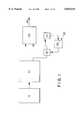
- FIG. 1is a block diagram of the respiratory gas dispensing apparatus.
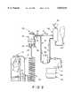
- FIG. 2is a schematic overview of the preferred embodiment of the respiratory gas dispensing apparatus.
- FIG. 3is a side plan view of the flow selector valve.
- FIG. 4is a plan view of the top of the flow selector valve.
- FIG. 5is a plan view of the bottom of the flow selector valve.
- FIG. 6is a cross-sectional view of the flow selector valve generally along line A--A of FIG. 4.
- FIG. 7is a cross-sectional view of the flow selector valve generally along line C--C of FIG. 3.
- FIG. 8is a cross-sectional view of the flow selector valve generally along line D--D of FIG. 3.
- FIG. 9Ais a square wave graph showing volume as a function of time from subject apparatus at 2 LPM.
- FIG. 9Bis a square wave graph showing volume as a function of time from subject apparatus at 4 LPM.
- FIG. 9Cis a square wave graph showing volume as a function of time from subject apparatus at 6 LPM.
- FIG. 10Ais a spike wave graph showing volume of air pulsed as a function of time from Puritan Bennett apparatus at 2 LPM.
- FIG. 10Bis a spike wave graph showing volume of air pulsed as a function of time from Puritan Bennett apparatus at 4 LPM.
- FIG. 10Cis a spike wave graph showing volume of air pulsed as a function of time from Puritan Bennett apparatus at 6 LPM.
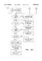
- FIG. 11Ais a flow chart for respiratory gas pulsed control.
- FIG. 11Bis a flow chart for respiratory gas pulsed control continued from FIG. 11A.
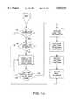
- FIG. 12Ais a flow chart for real time interrupt processing in respiratory gas pulsed control.
- FIG. 12Bis a flow chart for real time interrupt processing in respiratory gas pulsed control continued from FIG. 12A.
- FIG. 12Cis a flow chart for real time interrupt processing in respiratory gas pulsed control continued from FIG. 12B.
- FIG. 13is a flow chart for level sense and display.
- FIG. 14is a flow chart for liquid level sense and display.
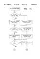
- FIG. 15is a flow chart for empty calibration.
- FIG. 16is a flow chart for full calibration.
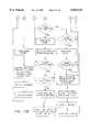
- FIG. 17is a schematic overview of an embodiment of the fail-safe respiratory gas dispensing apparatus.
- the subject inventionpertains to a respiratory apparatus which features a means for selecting either a continuous gas flow mode or a pulsed gas flow mode, and further, for controlling the volume of gas received by the patient.
- the subject apparatusprovides for varying the volume of flow in the continuous flow mode from about 0.25 LPM to about 6.0 LPM, and in the pulsed flow mode, from about 0.50 LPM to about 35.0 LPM.
- eleven different flow ratesare available in each of the continuous and pulsed flow modes.
- the subject system apparatusdelivers a continuous volume of respiratory gas at the selected flow rate over the entire pulse period, and within less than half of the inspiratory effort of the patient.
- the apparatusdelivers the desired volume of respiratory gas, at consistent flow rate, within the first 400 milliseconds of the inspiratory effort.
- the subject apparatusfurther provides a failsafe feature which detects a loss of power when in the pulse mode, and automatically fails to a continuous gas flow to the patient.
- a failsafe featurewhich detects a loss of power when in the pulse mode, and automatically fails to a continuous gas flow to the patient.
- FIG. 1is a basic block flow diagram generally illustrating the subject respiratory gas delivery system.
- the systemincludes a source of respiratory gas 10, a valve means 30 for delivering continuous flow or pulse flow respiratory gas, a solenoid valve 80 for controlling gas flow, a sensing means 110 for sensing inspiratory effort, a printed circuit board 90 including an onboard computer 92, a mode select switch 130, and an outlet, or cannula 140 to the patient.
- the term "patient” as used hereinis meant to include any user of the subject device.
- a heat exchanger 20may be used to vaporize the liquid into a gas suitable for delivery to the patient through the subject apparatus.
- the valve means 30may be a combination of valves for producing continuous and pulse gas flow. In the alternative, a single valve capable of delivering gas in both continuous and pulse mode may be used. It is an aspect of the invention that the valve means selected is capable of delivering gas in both continuous and pulse mode through distinct lines.
- lineis meant to mean any fluid conveying means, such as a duct, conduit, pipe, channel, or any other closed fluid conducting device.
- the sensing meansmay be any apparatus known to those skilled in the art which is capable of sensing the initiation of an inspiratory or negative effort. As will be seen with reference to the preferred embodiment of the invention, one such means is a mass flow sensor.
- the sensing meansis in electrical contact with the printed circuit board which converts the sensing of a negative or inspiratory effort to an electrical signal and transmits the same to the solenoid valve, resulting in release of a precise dose or pulse of respiratory gas.
- the mode select switch 130may be a manually operated switch or an automated switch controlled by printed circuit board 90 and the on-board computer. In one embodiment, when the subject respiratory gas delivery apparatus includes the fail-safe device disclosed hereinafter, the switch is automated in order for the fail-safe feature to function properly.
- FIG. 2represents the preferred embodiment of the invention.
- source of gas 10is a source of liquid oxygen.
- any respiratory gasmay be supplied, therefore any reference to oxygen is equally applicable to other respiratory gases.
- the sourcemay be a portable tank, a stationary tank, or may be a permanent wall capacity device.
- a fluid conducting line 12exits supply tank 10 and carries the liquid oxygen through heat exchanger 20 to vaporize the liquid into oxygen gas. This gas is then delivered through gas conducting line 22 into flow selector valve 30 through inlet port 32.
- a regulated gas flow control valve of the type shown in U.S. Pat. No. 4,655,246, the disclosure of which is incorporated herein by reference,is generally suitable for use in the subject invention with changes as indicated herein below.
- the valve disclosed in the 4,655,246 patentcomprises a regulated gas flow control valve, including a valve body having an inlet at one end for receiving gas from a supply tank or other respiratory gas source.
- a flow control selector knobis located at the other end of the valve body. The knob selects a preselected flow rate for delivery of gas through an outlet.
- the knobcontrols position of a rotor carrying a plurality of pre-calibrated flow control orifice inserts, the knob being rotatable but with positive detenting for orienting the rotor to permit flow only through the pre-selected orifice for delivery to the patient.
- the subject valvediffers from the valve disclosed in the 4,655,246 patent in a variety of ways including that it has dual outlet ports, one port designated for use in the continuous flow mode, and a second port designated for use in the pulsed flow mode.
- the valve of the subject inventionfurther differs from that in the 4,655,246 patent in that the subject valve rotor has 24 orifices configured for allowing the communication of a wide range of volumetric flows of respirating gas to the patient during normal operation and emergency operation.
- the flow selector valve of the subject inventionhas, as was stated herein above, an inlet port 32 for receiving gas from a supply tank or other gas source 10, through gas conducting line 22.
- the flow selector valvehas relief valves 34 and 36, which is an arrangement common to the valve industry for maintaining valve pressure at acceptable levels.
- Gas received through inlet port 32is immediately communicated through two of the 24 orifices in a rotatable disc 40 (See FIG. 8) within the flow selector valve 30. This disc, as well as the remaining parts of the valve, will be discussed in more detail with reference to FIGS. 3-8 in the disclosure set forth hereafter. Now then, gas is transmitted through valve 30 and then exits the valve dual outlet ports 60 and 62, only one of which is ultimately in open communication with the outlet or cannula 140 at any given time. Outlet port 60 is a low flow rate port and is designated for use in the continuous mode. Outlet port 62 is a high flow rate port used only for pulse flow dosing.
- the low and high outlet portsare connected by flow lines 70 and 72 respectively to mode select switch 130.
- This switchallows the user to operate the device in a continuous mode or in a pulse mode, but not in both modes simultaneously. Because only one of flow lines 70,72 is in open communication with the outlet or cannula 140 at a given time, there is no danger of over oxygenation of the user or patient due to inhalation of excess pulsed air while receiving a regulated continuous flow of oxygen.
- the mode select switch 130is a manual switch, though an automated switch may also be used.
- the mode select switch 130has a toggle 132.
- toggle 132 of the mode select switch 130is in the continuous mode, or deflected to the right as shown by dotted line in FIG. 2, oxygen flows continuously through flow line 70 into cannula 140 and is received by the user or patient.
- toggle 132 of the mode select switch 130When toggle 132 of the mode select switch 130 is in the pulse mode, or deflected to the left as shown by solid line in FIG. 2, a precise dose of oxygen is pulsed through line 72 to and ultimately through cannula 140 after travelling through solenoid valve 80 and through mode select switch 130. Gas emitted in the pulse mode is received by the patient within the first 400 milliseconds of inspiration.
- the flow selector valve 30is a dual outlet port valve capable of delivering gas to the patient in numerous different volumes and in either continuous or pulsed flow.
- FIG. 3is a plan view of flow selector valve 30. Dual outlet ports 60 and 62 are shown side-by-side on the upper portion of the valve. Outlet port 60 includes a reduced opening 60a to assist in achieving its relatively low flow rate when the overall system is operating in the continuous flow mode and outlet port 62 includes an opening 62a greater than the reduced opening 60a to assist in achieving its relatively high flow rate when the overall system is operating in the pulsed flow mode.
- FIG. 4shows a top view of the valve shown in FIG. 3.
- Knob 58is used to dial the appropriate volume of gas flow.
- Outlet ports 60 and 62are seated in channel 64.
- FIG. 5is a plan view of the bottom of valve 30 showing inlet port 32 and relief valves 34 and 36. Now, in use, as air enters the flow selector valve 30 through inlet port 32, it is communicated to and evenly distributed in chamber 38 which is shown in FIG. 6 which is a cross-sectional view of the valve generally along line A--A of FIG. 4. Seated in chamber 38 is a rotatable disc 40. Disc 40, has twenty four orifices 40,42 inscribed therein which define gas communicating apertures extending from the lower surface of disc 40, seen in FIG. 8, through to the upper surface of disc 40 which abuts rotor 52, shown in FIG. 7. Two of these orifices, 42a and 44a, are seen in FIG. 6. As illustrated in FIG.
- the orificesare arranged on disc 40 in two concentric rings of twelve orifices each, the outer ring orifices 44 being of a larger overall diameter than the inner ring orifices 42. All of the orifices in inner ring 42 being the same size as all of the orifices in the outer ring 44 of the same size.
- the orificesare arranged in the concentric rings 42 and 44 such that when in use, a given pair of outer and inner orifices allow the same relative flow volume in continuous or pulse flow mode, i.e. if the inner orifice in communicating position allows a continuous flow of 0.25 LPM, the outer orifice in communicating position allows a pulse flow of 0.50 LPM.
- a plate 46In intimate contact with the top face of disc 40 is a plate 46, seen in FIG. 6, having various sized apertures therethrough, each of which coordinates with one of the orifices in disc 40.
- the variation in size of these aperturescan be seen in FIG. 8 as openings 48, corresponding to the inner orifices 42 of disc 40, and 50, corresponding to the outer orifices 44 of disc 40.
- the apertures 48 and 50 in plate 46range in size generally from about 0.003 to 0.041 inches.
- FIG. 7is a cross-sectional view generally along line C--C of FIG. 3.
- Rotor 52has one aperture 54 which communicates with the inner orifices 48 of the disc 40/plate 46 combination and another aperture 56 which communicates with the outer orifices 50 on the disc 40/plate 46 combination.
- Knob 58allows the user to rotate disc 40, permitting flow through only one inner orifice 48 or one outer orifice 50 as it is brought into line with inner aperture 54 and outer aperture 56 on rotor 52. Positive detenting of knob 58 maintains disc 40 in the selected position with respect to rotor apertures 54 and 56.
- two of the twenty-four orificesare in operative communicating pairs at any given time.
- the various size orificesare arranged such that the communicating orifice pairs will have the same relative flow rate, thus ensuring the same relative flow type in continuous or pulse mode.
- Such pairsare shown in TABLE I. The full import of this arrangement will be more clearly understood by the reader with reference to FIG. 17, discussed hereinbelow.
- aperture 54communicates air through outlet port 60, and aperture 56 communicates air through port 62.
- Continuous line 70connects outlet port 60 to mode selector switch 130.
- Pulse flow line 72likewise connects outlet port 62 to mode selector switch 130.
- gasis transmitted through continuous flow line 70 to mode selector switch 130 and then on to the patient through cannula 140.
- mode selector switch 130When in the pulse flow mode position, mode selector switch 130 closes continuous flow line 70 and allows air to be pulsed through pulse line 72. This is achieved in the following manner. With mode selector switch 130 in the pulse position, energy is exerted on a pin, not shown, within mode selector switch 130 which in turn causes a release of energy to circuit board 90. Switches capable of achieving this release of energy are known to those skilled in the art and therefore no further description of the operation of this switch is deemed to be necessary at this point. One type of switch which may be used to achieve the desired results is a spool switch.
- the mass flow sensor 110As the patient inhales, the mass flow sensor 110, connected to the cannula 140 through line 72, senses a negative effort. Within one millisecond of sensing this negative effort, the mass flow sensor emits a signal to the printed circuit board 90 which in turn causes solenoid valve 80 to open allowing a precisely dosed pulse of gas to pass through line 72 to cannula 140 and on to the patient. Solenoid valve 80 is closed within precisely 400 milliseconds, thus ensuring that the entire amount of pulse gas reaches the patient within the first quarter to one-eighth of the inhalation.
- FIGS. 9A-9C and 10A-10Care graphs representing the volume of oxygen received by the patient as a function of time.
- FIGS. 9A-9Ccorrespond to use of the subject device as described herein above and shown in FIGS. 1-8. These graphs clearly illustrate the capability of the subject apparatus to deliver the desired volume of respiratory gas within the first 400 milliseconds of inspiration.
- FIG. 9Arepresents a flow rate of 2 LPM, corresponding to the area under the pulse, within the allotted time.
- the graphsverify delivery of 4 LPM and 6 LPM respectively within the same time period. Further, these graphs demonstrate that the volume or flow rate, determined by the y axis of the graph, is consistent throughout the entire pulse period, i.e. the pulse is a "square pulse".
- FIGS. 10A-10Cillustrate the wave graph produced by a Puritan Bennett Portable Pulse apparatus in delivering the same volume as in FIGS. 9A-9C, i.e., 2 LPM, 4 LPM, and 6 LPM.
- This apparatushas a fixed volumetric bolus the content of which is released in response to sensing of a negative effort as the patient inhales.
- the bolusis constantly being refilled, therefore the patient receives the full pulse of respiratory gas contained in the bolus, shown as a spike in these graphs, and then a trailing off or constant supply, shown as a downward slope to a flat line after the spike.
- the volume of respiratory gas delivered to the patientvaries over a single pulse period due to the spike.
- the bolusis of a set volume when it is necessary to deliver higher flow rate such as 6 LPM (See FIG. 10C), the patient will not receive the necessary amount of oxygen in the 400 millisecond time period. Obviously, this system also is less efficient in oxygen conservation due to the trailing effect experienced during bolus refill.
- Printed circuit board 90includes an onboard computer 92.
- the computerhas control software which includes an overall control program, as shown generally in FIGS. 11A-11B.
- Other operations maintained by the computer 92are a real time interrupt program, such as that shown generally at FIGS. 12A-12C for controlling inspiration and battery operations.
- the computercontrols a level sense and display mainline program, such as that shown generally at FIG. 13, a liquid level sense and display program, such as that shown generally at FIG. 14, an empty calibration program, such as that shown generally at FIG. 15, and a full calibration program, such as that shown generally at FIG. 16.
- FIG. 17represents another embodiment of the subject invention which includes the fail-safe feature as part of the respiratory gas delivery apparatus.
- continuous flow line 70has a solenoid valve 84 which is controlled by printed circuit board 90 and powered, therefore, by batter 100.
- poweris used to maintain the solenoid valve 84 in the closed position, allowing flow of pulsed air through line 72 as disclosed hereinabove. If the power supply of the apparatus fails, solenoid valve 80 will remain in the closed position due to lack of power.
- solenoid valve 84will be left open due to lack of power, thereby permitting delivery of a continuous flow of gas to the patient.
- the continuous flow ratewill be in keeping with the pulse flow rate the patient was receiving prior to the power failure.
- the systemis calibrated to a timing sequence specific to the breathing of the individual user. For instance, the system may be calibrated to a 20 second time interval, during which time 3 equally spaced breaths, approximately six seconds apart, of the selected pulse size and shape are automatically delivered. If the system experiences a loss of power or computer malfunction, the pulse mode is disengaged and the continuous mode engaged.
- the devicedue to the variation in volume provided by using the flow selector valve which is the subject hereof, offers the advantage of delivering a precise dose of respiratory gas even in the continuous flow mode by setting the selector to the prescribed volume.
Landscapes
- Health & Medical Sciences (AREA)
- Heart & Thoracic Surgery (AREA)
- Life Sciences & Earth Sciences (AREA)
- Engineering & Computer Science (AREA)
- Anesthesiology (AREA)
- Biomedical Technology (AREA)
- Emergency Medicine (AREA)
- Hematology (AREA)
- Pulmonology (AREA)
- Animal Behavior & Ethology (AREA)
- General Health & Medical Sciences (AREA)
- Public Health (AREA)
- Veterinary Medicine (AREA)
- Respiratory Apparatuses And Protective Means (AREA)
- Measurement Of The Respiration, Hearing Ability, Form, And Blood Characteristics Of Living Organisms (AREA)
Abstract
Description
TABLE I __________________________________________________________________________FLOW RATE COORDINATION, LPM __________________________________________________________________________LOW FLOW RATE 0.25 .050 .075 1.0 1.5 2.0 2.5 3.0 4.0 5.0 6.0 HIGH FLOW RATE 0.50 1.0 1.5 2.0 3.0 4.0 7.5 10.5 16.0 25.0 35.0 __________________________________________________________________________
Claims (17)
Priority Applications (4)
| Application Number | Priority Date | Filing Date | Title |
|---|---|---|---|
| US08/153,569US5839434A (en) | 1993-11-16 | 1993-11-16 | Method and apparatus for dispensing respiratory gases |
| CA002132268ACA2132268A1 (en) | 1993-11-16 | 1994-09-16 | Respiratory gases |
| SE9403516ASE9403516L (en) | 1993-11-16 | 1994-10-14 | Methods and devices for the release of respiratory gases |
| EP94308088AEP0657182A3 (en) | 1993-11-16 | 1994-11-02 | Method and apparatus for dispensing respiratory gases. |
Applications Claiming Priority (1)
| Application Number | Priority Date | Filing Date | Title |
|---|---|---|---|
| US08/153,569US5839434A (en) | 1993-11-16 | 1993-11-16 | Method and apparatus for dispensing respiratory gases |
Publications (1)
| Publication Number | Publication Date |
|---|---|
| US5839434Atrue US5839434A (en) | 1998-11-24 |
Family
ID=22547752
Family Applications (1)
| Application Number | Title | Priority Date | Filing Date |
|---|---|---|---|
| US08/153,569Expired - LifetimeUS5839434A (en) | 1993-11-16 | 1993-11-16 | Method and apparatus for dispensing respiratory gases |
Country Status (4)
| Country | Link |
|---|---|
| US (1) | US5839434A (en) |
| EP (1) | EP0657182A3 (en) |
| CA (1) | CA2132268A1 (en) |
| SE (1) | SE9403516L (en) |
Cited By (33)
| Publication number | Priority date | Publication date | Assignee | Title |
|---|---|---|---|---|
| WO1999061090A1 (en)* | 1998-05-22 | 1999-12-02 | Duke University | Method and apparatus for supplemental oxygen delivery |
| US6164276A (en)* | 1997-05-16 | 2000-12-26 | Datex-Ohmeda, Inc. | Accurate dose nitric oxide pulse delivery device with monitoring and alarms |
| US20030140924A1 (en)* | 2001-11-06 | 2003-07-31 | Aylsworth Alonzo C. | Therapeutic gas conserver and control |
| US6631716B1 (en) | 1998-07-17 | 2003-10-14 | The Board Of Trustees Of The Leland Stanford Junior University | Dynamic respiratory control |
| US20050005942A1 (en)* | 2003-07-09 | 2005-01-13 | Airmatrix Technologies, Inc. | Method and system for measuring airflow of nares |
| US20050092321A1 (en)* | 2003-10-29 | 2005-05-05 | Airmatrix Technologies, Inc. | Method and system of sensing airflow and delivering therapeutic gas to a patient |
| US20050103342A1 (en)* | 2003-11-14 | 2005-05-19 | Jorczak Kevin D. | Remote control gas regulation system |
| US6910482B2 (en) | 2001-10-19 | 2005-06-28 | Chart Inc. | Self-calibrating supplemental oxygen delivery system |
| US20060060198A1 (en)* | 2004-09-17 | 2006-03-23 | Acoba, Llc | Method and system of scoring sleep disordered breathing |
| US7066985B2 (en) | 2003-10-07 | 2006-06-27 | Inogen, Inc. | Portable gas fractionalization system |
| US20060169281A1 (en)* | 2005-02-03 | 2006-08-03 | Aylsworth Alonzo C | Continuous flow selective delivery of therapeutic gas |
| US7135059B2 (en) | 2003-10-07 | 2006-11-14 | Inogen, Inc. | Portable gas fractionalization system |
| US7201166B2 (en) | 1997-04-04 | 2007-04-10 | Gilbert Blaise | Injection system for delivery of a gaseous substance |
| US20080178881A1 (en)* | 2007-01-31 | 2008-07-31 | Ric Investments, Llc | System and method for oxygen therapy |
| US7438745B2 (en) | 2003-10-07 | 2008-10-21 | Inogen, Inc. | Portable gas fractionalization system |
| US20080302363A1 (en)* | 2007-06-05 | 2008-12-11 | Allied Healthcare Products, Inc. | Ventilator apparatus |
| US20090065007A1 (en)* | 2007-09-06 | 2009-03-12 | Wilkinson William R | Oxygen concentrator apparatus and method |
| US7522972B1 (en) | 2005-06-10 | 2009-04-21 | Beauford Basped | Oxygen vending machine |
| USD606655S1 (en) | 2008-06-27 | 2009-12-22 | Inova Labs, Llc | Portable oxygen concentrator |
| US7686870B1 (en) | 2005-12-29 | 2010-03-30 | Inogen, Inc. | Expandable product rate portable gas fractionalization system |
| US7922789B1 (en) | 2003-10-07 | 2011-04-12 | Inogen, Inc. | Portable gas fractionalization system |
| US8226597B2 (en) | 2002-06-21 | 2012-07-24 | Baxter International, Inc. | Fluid delivery system and flow control therefor |
| US8251876B2 (en) | 2008-04-22 | 2012-08-28 | Hill-Rom Services, Inc. | Breathing exercise apparatus |
| US20130087146A1 (en)* | 2009-11-11 | 2013-04-11 | Matthew John Callaghan | Ventilation systems and methods |
| US8603228B2 (en) | 2010-09-07 | 2013-12-10 | Inova Labs, Inc. | Power management systems and methods for use in an oxygen concentrator |
| US8616207B2 (en) | 2010-09-07 | 2013-12-31 | Inova Labs, Inc. | Oxygen concentrator heat management system and method |
| US9180271B2 (en) | 2012-03-05 | 2015-11-10 | Hill-Rom Services Pte. Ltd. | Respiratory therapy device having standard and oscillatory PEP with nebulizer |
| US9440179B2 (en) | 2014-02-14 | 2016-09-13 | InovaLabs, LLC | Oxygen concentrator pump systems and methods |
| US9440180B2 (en) | 2012-10-12 | 2016-09-13 | Inova Labs, Llc | Oxygen concentrator systems and methods |
| US9440036B2 (en) | 2012-10-12 | 2016-09-13 | InovaLabs, LLC | Method and systems for the delivery of oxygen enriched gas |
| US9717876B2 (en) | 2012-10-12 | 2017-08-01 | Inova Labs, Inc. | Dual oxygen concentrator systems and methods |
| US10905836B2 (en) | 2015-04-02 | 2021-02-02 | Hill-Rom Services Pte. Ltd. | Manifold for respiratory device |
| US11458274B2 (en) | 2016-05-03 | 2022-10-04 | Inova Labs, Inc. | Method and systems for the delivery of oxygen enriched gas |
Families Citing this family (2)
| Publication number | Priority date | Publication date | Assignee | Title |
|---|---|---|---|---|
| US5865174A (en)* | 1996-10-29 | 1999-02-02 | The Scott Fetzer Company | Supplemental oxygen delivery apparatus and method |
| FR2888120B1 (en)* | 2005-07-07 | 2008-07-04 | Cryo Diffusion S A Sa | DEVICE FOR STORING AND SUPPLYING CRYOGENIC FLUID, PARTICULARLY FOR BREATHING AND OXYGEN THERAPY |
Citations (15)
| Publication number | Priority date | Publication date | Assignee | Title |
|---|---|---|---|---|
| US4210136A (en)* | 1977-07-14 | 1980-07-01 | Apple Wayne R | Apparatus for automatic ventilation of the lungs |
| US4414982A (en)* | 1980-11-26 | 1983-11-15 | Tritec Industries, Inc. | Apneic event detector and method |
| US4457303A (en)* | 1980-11-26 | 1984-07-03 | Tritec Industries, Inc. | Respirating gas supply control method and apparatus therefor |
| US4461293A (en)* | 1982-12-03 | 1984-07-24 | Kircaldie, Randall, And Mcnab | Respirating gas supply method and apparatus therefor |
| US4481944A (en)* | 1981-11-19 | 1984-11-13 | Bunnell Life Systems, Inc. | Apparatus and method for assisting respiration |
| US4484578A (en)* | 1980-11-26 | 1984-11-27 | Kircaldie, Randall And Mcnab | Respirator apparatus and method |
| US4584996A (en)* | 1984-03-12 | 1986-04-29 | Blum Alvin S | Apparatus for conservative supplemental oxygen therapy |
| US4648395A (en)* | 1982-07-07 | 1987-03-10 | Sanyo Densihkogyo Co. Ltd. | Synchronized feed type oxygen concentrator for use in an open breathing system |
| US4655246A (en)* | 1983-09-30 | 1987-04-07 | Essex Industries, Inc. | Regulated gas flow control valve |
| US4686974A (en)* | 1985-10-18 | 1987-08-18 | Tottori University | Breath synchronized gas-insufflation device and method therefor |
| US4705034A (en)* | 1985-10-02 | 1987-11-10 | Perkins Warren E | Method and means for dispensing respirating gases by effecting a known displacement |
| US4823788A (en)* | 1988-04-18 | 1989-04-25 | Smith Richard F M | Demand oxygen controller and respiratory monitor |
| US4832014A (en)* | 1985-10-02 | 1989-05-23 | Perkins Warren E | Method and means for dispensing two respirating gases by effecting a known displacement |
| US5038770A (en)* | 1989-02-03 | 1991-08-13 | Perkins Warren E | Fail-safe systems for respirating gas delivery devices |
| US5603315A (en)* | 1995-08-14 | 1997-02-18 | Reliable Engineering | Multiple mode oxygen delivery system |
Family Cites Families (4)
| Publication number | Priority date | Publication date | Assignee | Title |
|---|---|---|---|---|
| US4211086A (en)* | 1977-10-11 | 1980-07-08 | Beatrice Foods Company | Cryogenic breathing system |
| FR2546292B1 (en)* | 1983-05-19 | 1986-11-14 | Vasse Ind Sa | FLOW METER FOR MEASURING THE FLOW OF A GASEOUS FLUID |
| US4938212A (en)* | 1987-10-16 | 1990-07-03 | Puritan-Bennett Corporation | Inspiration oxygen saver |
| US4971049A (en)* | 1989-11-06 | 1990-11-20 | Pulsair, Inc. | Pressure sensor control device for supplying oxygen |
- 1993
- 1993-11-16USUS08/153,569patent/US5839434A/ennot_activeExpired - Lifetime
- 1994
- 1994-09-16CACA002132268Apatent/CA2132268A1/ennot_activeAbandoned
- 1994-10-14SESE9403516Apatent/SE9403516L/ennot_activeApplication Discontinuation
- 1994-11-02EPEP94308088Apatent/EP0657182A3/ennot_activeWithdrawn
Patent Citations (20)
| Publication number | Priority date | Publication date | Assignee | Title |
|---|---|---|---|---|
| US4210136A (en)* | 1977-07-14 | 1980-07-01 | Apple Wayne R | Apparatus for automatic ventilation of the lungs |
| US4414982A (en)* | 1980-11-26 | 1983-11-15 | Tritec Industries, Inc. | Apneic event detector and method |
| US4457303A (en)* | 1980-11-26 | 1984-07-03 | Tritec Industries, Inc. | Respirating gas supply control method and apparatus therefor |
| US4484578A (en)* | 1980-11-26 | 1984-11-27 | Kircaldie, Randall And Mcnab | Respirator apparatus and method |
| US4481944A (en)* | 1981-11-19 | 1984-11-13 | Bunnell Life Systems, Inc. | Apparatus and method for assisting respiration |
| US4648395A (en)* | 1982-07-07 | 1987-03-10 | Sanyo Densihkogyo Co. Ltd. | Synchronized feed type oxygen concentrator for use in an open breathing system |
| US4462398A (en)* | 1982-12-03 | 1984-07-31 | Kircaldie, Randal and McNab, Trustee | Respirating gas supply method and apparatus therefor |
| US4506666A (en)* | 1982-12-03 | 1985-03-26 | Kircaldie, Randall And Mcnab | Method and apparatus for rectifying obstructive apnea |
| US4519387A (en)* | 1982-12-03 | 1985-05-28 | Kircaldie, Randall And Mcnab, Trustee | Respirating gas supply method and apparatus therefor |
| US4461293A (en)* | 1982-12-03 | 1984-07-24 | Kircaldie, Randall, And Mcnab | Respirating gas supply method and apparatus therefor |
| US4655246A (en)* | 1983-09-30 | 1987-04-07 | Essex Industries, Inc. | Regulated gas flow control valve |
| US4584996A (en)* | 1984-03-12 | 1986-04-29 | Blum Alvin S | Apparatus for conservative supplemental oxygen therapy |
| US4832014A (en)* | 1985-10-02 | 1989-05-23 | Perkins Warren E | Method and means for dispensing two respirating gases by effecting a known displacement |
| US4705034A (en)* | 1985-10-02 | 1987-11-10 | Perkins Warren E | Method and means for dispensing respirating gases by effecting a known displacement |
| US4873971A (en)* | 1985-10-02 | 1989-10-17 | Perkins Warren E | Method and means for dispensing respirating gases by effecting a known displacement |
| US5005570A (en)* | 1985-10-02 | 1991-04-09 | Perkins Warren E | Method and means for dispensing respirating gases by effecting a known displacement |
| US4686974A (en)* | 1985-10-18 | 1987-08-18 | Tottori University | Breath synchronized gas-insufflation device and method therefor |
| US4823788A (en)* | 1988-04-18 | 1989-04-25 | Smith Richard F M | Demand oxygen controller and respiratory monitor |
| US5038770A (en)* | 1989-02-03 | 1991-08-13 | Perkins Warren E | Fail-safe systems for respirating gas delivery devices |
| US5603315A (en)* | 1995-08-14 | 1997-02-18 | Reliable Engineering | Multiple mode oxygen delivery system |
Cited By (64)
| Publication number | Priority date | Publication date | Assignee | Title |
|---|---|---|---|---|
| US7201166B2 (en) | 1997-04-04 | 2007-04-10 | Gilbert Blaise | Injection system for delivery of a gaseous substance |
| US6164276A (en)* | 1997-05-16 | 2000-12-26 | Datex-Ohmeda, Inc. | Accurate dose nitric oxide pulse delivery device with monitoring and alarms |
| US6192884B1 (en)* | 1998-05-22 | 2001-02-27 | Duke University | Method and apparatus for supplemental oxygen delivery |
| WO1999061090A1 (en)* | 1998-05-22 | 1999-12-02 | Duke University | Method and apparatus for supplemental oxygen delivery |
| US6631716B1 (en) | 1998-07-17 | 2003-10-14 | The Board Of Trustees Of The Leland Stanford Junior University | Dynamic respiratory control |
| US6910482B2 (en) | 2001-10-19 | 2005-06-28 | Chart Inc. | Self-calibrating supplemental oxygen delivery system |
| US20030140924A1 (en)* | 2001-11-06 | 2003-07-31 | Aylsworth Alonzo C. | Therapeutic gas conserver and control |
| US8672876B2 (en) | 2002-06-21 | 2014-03-18 | Baxter International Inc. | Fluid delivery system and flow control therefor |
| US8226597B2 (en) | 2002-06-21 | 2012-07-24 | Baxter International, Inc. | Fluid delivery system and flow control therefor |
| US8231566B2 (en) | 2002-06-21 | 2012-07-31 | Baxter International, Inc. | Fluid delivery system and flow control therefor |
| US7066180B2 (en) | 2003-07-09 | 2006-06-27 | Airmatrix Technologies, Inc. | Method and system for measuring airflow of nares |
| US20050005942A1 (en)* | 2003-07-09 | 2005-01-13 | Airmatrix Technologies, Inc. | Method and system for measuring airflow of nares |
| US7135059B2 (en) | 2003-10-07 | 2006-11-14 | Inogen, Inc. | Portable gas fractionalization system |
| US7066985B2 (en) | 2003-10-07 | 2006-06-27 | Inogen, Inc. | Portable gas fractionalization system |
| US7753996B1 (en) | 2003-10-07 | 2010-07-13 | Inogen, Inc. | Portable gas fractionalization system |
| US7922789B1 (en) | 2003-10-07 | 2011-04-12 | Inogen, Inc. | Portable gas fractionalization system |
| US7730887B2 (en) | 2003-10-07 | 2010-06-08 | Inogen, Inc. | Portable gas fractionalization system |
| US7438745B2 (en) | 2003-10-07 | 2008-10-21 | Inogen, Inc. | Portable gas fractionalization system |
| US7007692B2 (en) | 2003-10-29 | 2006-03-07 | Airmatrix Technologies, Inc. | Method and system of sensing airflow and delivering therapeutic gas to a patient |
| US20050092321A1 (en)* | 2003-10-29 | 2005-05-05 | Airmatrix Technologies, Inc. | Method and system of sensing airflow and delivering therapeutic gas to a patient |
| US20050126571A1 (en)* | 2003-11-14 | 2005-06-16 | Jorczak Kevin D. | Remote control fluid regulation system |
| US7552731B2 (en) | 2003-11-14 | 2009-06-30 | Remcore, Inc. | Remote control gas regulation system |
| US8499761B2 (en) | 2003-11-14 | 2013-08-06 | Remcore, Inc. | Remote control fluid regulation system |
| US7753049B2 (en) | 2003-11-14 | 2010-07-13 | Remcore, Inc. | Remote control fluid regulation system |
| US20100237265A1 (en)* | 2003-11-14 | 2010-09-23 | Jorczak Kevin D | Remote control fluid regulation system |
| US20050103342A1 (en)* | 2003-11-14 | 2005-05-19 | Jorczak Kevin D. | Remote control gas regulation system |
| US20060060198A1 (en)* | 2004-09-17 | 2006-03-23 | Acoba, Llc | Method and system of scoring sleep disordered breathing |
| US20060169281A1 (en)* | 2005-02-03 | 2006-08-03 | Aylsworth Alonzo C | Continuous flow selective delivery of therapeutic gas |
| US7522972B1 (en) | 2005-06-10 | 2009-04-21 | Beauford Basped | Oxygen vending machine |
| US7686870B1 (en) | 2005-12-29 | 2010-03-30 | Inogen, Inc. | Expandable product rate portable gas fractionalization system |
| US9186476B2 (en)* | 2007-01-31 | 2015-11-17 | Ric Investments, Llc | System and method for oxygen therapy |
| US20080178881A1 (en)* | 2007-01-31 | 2008-07-31 | Ric Investments, Llc | System and method for oxygen therapy |
| EP2162176A4 (en)* | 2007-06-05 | 2015-04-01 | Allied Healthcare Prod | Improved ventilator apparatus |
| US8656913B2 (en)* | 2007-06-05 | 2014-02-25 | Allied Healthcare Products, Inc. | Ventilator apparatus |
| US20080302363A1 (en)* | 2007-06-05 | 2008-12-11 | Allied Healthcare Products, Inc. | Ventilator apparatus |
| WO2008153867A1 (en) | 2007-06-05 | 2008-12-18 | Allied Healthcare Products, Inc. | Improved ventilator apparatus |
| US9649465B2 (en) | 2007-09-06 | 2017-05-16 | Inova Labs, Inc. | Oxygen concentrator apparatus and method having variable operation modes |
| US20110030686A1 (en)* | 2007-09-06 | 2011-02-10 | Inova Labs, Inc. | Oxygen concentrator apparatus and method having variable operation modes |
| US9956370B2 (en) | 2007-09-06 | 2018-05-01 | Inova, Labs, LLC. | Oxygen concentrator apparatus and method having flow restricted coupling of the canisters |
| US20110030689A1 (en)* | 2007-09-06 | 2011-02-10 | Inova Labs, Inc. | Oxygen concentrator apparatus and method having an ultrasonic detector |
| US9649464B2 (en) | 2007-09-06 | 2017-05-16 | Inova Labs, Inc. | Oxygen concentrator apparatus and method having an ultrasonic detector |
| US20110030685A1 (en)* | 2007-09-06 | 2011-02-10 | Wilkinson William R | Oxygen concentrator apparatus and method of delivering pulses of oxygen |
| US20110030687A1 (en)* | 2007-09-06 | 2011-02-10 | Inova Labs, Inc. | Oxygen concentrator apparatus and method with an oxygen assisted venting system |
| US20110030684A1 (en)* | 2007-09-06 | 2011-02-10 | Inova Labs, Inc. | Oxygen concentrator apparatus and method having flow restricted coupling of the canisters |
| US20090065007A1 (en)* | 2007-09-06 | 2009-03-12 | Wilkinson William R | Oxygen concentrator apparatus and method |
| US8794237B2 (en) | 2007-09-06 | 2014-08-05 | Inova Labs, Inc. | Oxygen concentrator apparatus and method having flow restricted coupling of the canisters |
| US8915248B2 (en) | 2007-09-06 | 2014-12-23 | Inova Labs, Inc. | Oxygen concentrator apparatus and method with an oxygen assisted venting system |
| US8251876B2 (en) | 2008-04-22 | 2012-08-28 | Hill-Rom Services, Inc. | Breathing exercise apparatus |
| USD606655S1 (en) | 2008-06-27 | 2009-12-22 | Inova Labs, Llc | Portable oxygen concentrator |
| US20130087146A1 (en)* | 2009-11-11 | 2013-04-11 | Matthew John Callaghan | Ventilation systems and methods |
| US9707371B2 (en)* | 2009-11-11 | 2017-07-18 | The Board Of Trustees Of The Leland Stanford, Jr. University | Ventilation systems and methods |
| US8603228B2 (en) | 2010-09-07 | 2013-12-10 | Inova Labs, Inc. | Power management systems and methods for use in an oxygen concentrator |
| US8616207B2 (en) | 2010-09-07 | 2013-12-31 | Inova Labs, Inc. | Oxygen concentrator heat management system and method |
| US9180271B2 (en) | 2012-03-05 | 2015-11-10 | Hill-Rom Services Pte. Ltd. | Respiratory therapy device having standard and oscillatory PEP with nebulizer |
| US9440180B2 (en) | 2012-10-12 | 2016-09-13 | Inova Labs, Llc | Oxygen concentrator systems and methods |
| US9440036B2 (en) | 2012-10-12 | 2016-09-13 | InovaLabs, LLC | Method and systems for the delivery of oxygen enriched gas |
| US9717876B2 (en) | 2012-10-12 | 2017-08-01 | Inova Labs, Inc. | Dual oxygen concentrator systems and methods |
| US11364359B2 (en) | 2012-10-12 | 2022-06-21 | Inova Labs, Inc. | Method and systems for the delivery of oxygen enriched gas |
| US11684744B2 (en) | 2012-10-12 | 2023-06-27 | Inova Labs, Inc. | Method and systems for the delivery of oxygen enriched gas |
| US9440179B2 (en) | 2014-02-14 | 2016-09-13 | InovaLabs, LLC | Oxygen concentrator pump systems and methods |
| US10905836B2 (en) | 2015-04-02 | 2021-02-02 | Hill-Rom Services Pte. Ltd. | Manifold for respiratory device |
| US10905837B2 (en) | 2015-04-02 | 2021-02-02 | Hill-Rom Services Pte. Ltd. | Respiratory therapy cycle control and feedback |
| US11992611B2 (en) | 2015-04-02 | 2024-05-28 | Hill-Rom Services Pte. Ltd. | Respiratory therapy apparatus control |
| US11458274B2 (en) | 2016-05-03 | 2022-10-04 | Inova Labs, Inc. | Method and systems for the delivery of oxygen enriched gas |
Also Published As
| Publication number | Publication date |
|---|---|
| SE9403516D0 (en) | 1994-10-14 |
| EP0657182A3 (en) | 1995-09-13 |
| CA2132268A1 (en) | 1995-05-17 |
| SE9403516L (en) | 1995-05-17 |
| EP0657182A2 (en) | 1995-06-14 |
Similar Documents
| Publication | Publication Date | Title |
|---|---|---|
| US5839434A (en) | Method and apparatus for dispensing respiratory gases | |
| JP7562732B2 (en) | Respiratory Humidification System | |
| US6606989B1 (en) | Precise administration of a medicated aerosol via the lungs | |
| US5755224A (en) | Cylinder-mounted oxygen management device | |
| US5558086A (en) | Method and apparatus for the intermittent delivery of oxygen therapy to a person | |
| SU1745104A3 (en) | Breathing appliance | |
| US5423313A (en) | Respirator intended for connection to human or animal airways | |
| US6192883B1 (en) | Oxygen flow control system and method | |
| US10173019B2 (en) | Dry powder delivery device | |
| US20060011199A1 (en) | Dual sensor oxygen therapy device | |
| US20080078385A1 (en) | System and method for delivery of medication via inhalation | |
| JPH0838605A (en) | Anesthesia device | |
| JPH0557872B2 (en) | ||
| WO2016096056A1 (en) | Additive gas delivery apparatus with backup | |
| JP2006150096A (en) | Intermittent gas inhalator and its method | |
| JPH04317660A (en) | Device for administering breathing gas and at least one anesthetic agent | |
| EP0956064A1 (en) | Metered dose medication adaptor with improved incentive spirometer | |
| WO2008042734A2 (en) | Heliox delivery system and method with positive pressure support | |
| US11471638B2 (en) | Pressure support system valve | |
| EP0519742A1 (en) | Medical nebulizer control system | |
| JPH08187289A (en) | Supplying system of gas for respiration | |
| US12083275B2 (en) | Method of pressure control in a mechanical ventilator with non-proportional solenoid valves | |
| CN222533882U (en) | Oxygen mixing therapy system | |
| JP2002143308A (en) | Respiratory synchronization type oxygen supply device | |
| JP2002143305A (en) | Respiratory synchronization type oxygen supply device |
Legal Events
| Date | Code | Title | Description |
|---|---|---|---|
| AS | Assignment | Owner name:INVACARE CORPORATION, OHIO Free format text:ASSIGNMENT OF ASSIGNORS INTEREST;ASSIGNOR:ENTERLINE, JACK JOSEPH;REEL/FRAME:007103/0023 Effective date:19940812 | |
| STCF | Information on status: patent grant | Free format text:PATENTED CASE | |
| FPAY | Fee payment | Year of fee payment:4 | |
| FPAY | Fee payment | Year of fee payment:8 | |
| AS | Assignment | Owner name:NATIONAL CITY BANK, AS MULTICURRENCY COLLATERAL AG Free format text:NOTICE OF GRANT OF SECURITY INTEREST;ASSIGNOR:INVACARE CORPORATION;REEL/FRAME:019009/0134 Effective date:20070212 | |
| FPAY | Fee payment | Year of fee payment:12 | |
| SULP | Surcharge for late payment | Year of fee payment:11 | |
| AS | Assignment | Owner name:PNC BANK, NATIONAL ASSOCIATION, PENNSYLVANIA Free format text:SECURITY AGREEMENT;ASSIGNORS:INVACARE CORPORATION;ADAPTIVE SWITCH LABORATORIES, INC.;THE AFTERMARKET GROUP, INC.;AND OTHERS;REEL/FRAME:025473/0311 Effective date:20101028 | |
| AS | Assignment | Owner name:INVACARE CORPORATION, OHIO Free format text:RELEASE BY SECURED PARTY;ASSIGNOR:PNC BANK, NATIONAL ASSOCIATION;REEL/FRAME:063638/0261 Effective date:20230505 | |
| AS | Assignment | Owner name:INVACARE HCS, LLC, OHIO Free format text:RELEASE BY SECURED PARTY;ASSIGNOR:PNC BANK, NATIONAL ASSOCIATION;REEL/FRAME:063668/0679 Effective date:20230505 Owner name:INVACARE FLORIDA HOLDINGS, LLC, OHIO Free format text:RELEASE BY SECURED PARTY;ASSIGNOR:PNC BANK, NATIONAL ASSOCIATION;REEL/FRAME:063668/0679 Effective date:20230505 Owner name:GARDEN CITY MEDICAL INC., OHIO Free format text:RELEASE BY SECURED PARTY;ASSIGNOR:PNC BANK, NATIONAL ASSOCIATION;REEL/FRAME:063668/0679 Effective date:20230505 Owner name:FREEDOM DESIGNS, INC., OHIO Free format text:RELEASE BY SECURED PARTY;ASSIGNOR:PNC BANK, NATIONAL ASSOCIATION;REEL/FRAME:063668/0679 Effective date:20230505 Owner name:ROADRUNNER MOBILITY, INCORPORATED, OHIO Free format text:RELEASE BY SECURED PARTY;ASSIGNOR:PNC BANK, NATIONAL ASSOCIATION;REEL/FRAME:063668/0679 Effective date:20230505 Owner name:KUSCHALL, INC., OHIO Free format text:RELEASE BY SECURED PARTY;ASSIGNOR:PNC BANK, NATIONAL ASSOCIATION;REEL/FRAME:063668/0679 Effective date:20230505 Owner name:INVAMEX HOLDINGS LLC, OHIO Free format text:RELEASE BY SECURED PARTY;ASSIGNOR:PNC BANK, NATIONAL ASSOCIATION;REEL/FRAME:063668/0679 Effective date:20230505 Owner name:INVACARE SUPPLY GROUP, INC., OHIO Free format text:RELEASE BY SECURED PARTY;ASSIGNOR:PNC BANK, NATIONAL ASSOCIATION;REEL/FRAME:063668/0679 Effective date:20230505 Owner name:INVACARE INTERNATIONAL CORPORATION, OHIO Free format text:RELEASE BY SECURED PARTY;ASSIGNOR:PNC BANK, NATIONAL ASSOCIATION;REEL/FRAME:063668/0679 Effective date:20230505 Owner name:INVACARE HOLDINGS, LLC, OHIO Free format text:RELEASE BY SECURED PARTY;ASSIGNOR:PNC BANK, NATIONAL ASSOCIATION;REEL/FRAME:063668/0679 Effective date:20230505 Owner name:INVACARE FLORIDA CORPORATION, OHIO Free format text:RELEASE BY SECURED PARTY;ASSIGNOR:PNC BANK, NATIONAL ASSOCIATION;REEL/FRAME:063668/0679 Effective date:20230505 Owner name:INVACARE CREDIT CORPORATION, OHIO Free format text:RELEASE BY SECURED PARTY;ASSIGNOR:PNC BANK, NATIONAL ASSOCIATION;REEL/FRAME:063668/0679 Effective date:20230505 Owner name:INVACARE CONTINUING CARE, INC., OHIO Free format text:RELEASE BY SECURED PARTY;ASSIGNOR:PNC BANK, NATIONAL ASSOCIATION;REEL/FRAME:063668/0679 Effective date:20230505 Owner name:INVACARE CANADIAN HOLDINGS, LLC, OHIO Free format text:RELEASE BY SECURED PARTY;ASSIGNOR:PNC BANK, NATIONAL ASSOCIATION;REEL/FRAME:063668/0679 Effective date:20230505 Owner name:INVACARE CANADIAN HOLDINGS, INC., OHIO Free format text:RELEASE BY SECURED PARTY;ASSIGNOR:PNC BANK, NATIONAL ASSOCIATION;REEL/FRAME:063668/0679 Effective date:20230505 Owner name:THE HELIXX GROUP, INC., OHIO Free format text:RELEASE BY SECURED PARTY;ASSIGNOR:PNC BANK, NATIONAL ASSOCIATION;REEL/FRAME:063668/0679 Effective date:20230505 Owner name:FAMILY MEDICAL SUPPLY LLC, OHIO Free format text:RELEASE BY SECURED PARTY;ASSIGNOR:PNC BANK, NATIONAL ASSOCIATION;REEL/FRAME:063668/0679 Effective date:20230505 Owner name:CHAMPION MANUFACTURING INC., OHIO Free format text:RELEASE BY SECURED PARTY;ASSIGNOR:PNC BANK, NATIONAL ASSOCIATION;REEL/FRAME:063668/0679 Effective date:20230505 Owner name:CENTRALIZED MEDICAL EQUIPMENT LLC, OHIO Free format text:RELEASE BY SECURED PARTY;ASSIGNOR:PNC BANK, NATIONAL ASSOCIATION;REEL/FRAME:063668/0679 Effective date:20230505 Owner name:ALTIMATE MEDICAL, INC., OHIO Free format text:RELEASE BY SECURED PARTY;ASSIGNOR:PNC BANK, NATIONAL ASSOCIATION;REEL/FRAME:063668/0679 Effective date:20230505 Owner name:THE AFTERMARKET GROUP, INC., OHIO Free format text:RELEASE BY SECURED PARTY;ASSIGNOR:PNC BANK, NATIONAL ASSOCIATION;REEL/FRAME:063668/0679 Effective date:20230505 Owner name:ADAPTIVE SWITCH LABORATORIES, INC., OHIO Free format text:RELEASE BY SECURED PARTY;ASSIGNOR:PNC BANK, NATIONAL ASSOCIATION;REEL/FRAME:063668/0679 Effective date:20230505 Owner name:INVACARE CORPORATION, OHIO Free format text:RELEASE BY SECURED PARTY;ASSIGNOR:PNC BANK, NATIONAL ASSOCIATION;REEL/FRAME:063668/0679 Effective date:20230505 Owner name:INVACARE OUTCOMES MANAGEMENT LLC, OHIO Free format text:RELEASE BY SECURED PARTY;ASSIGNOR:PNC BANK, NATIONAL ASSOCIATION;REEL/FRAME:063668/0639 Effective date:20230505 Owner name:INVAMEX HOLDINGS LLC, OHIO Free format text:RELEASE BY SECURED PARTY;ASSIGNOR:PNC BANK, NATIONAL ASSOCIATION;REEL/FRAME:063668/0639 Effective date:20230505 Owner name:INVACARE INTERNATIONAL CORPORATION, OHIO Free format text:RELEASE BY SECURED PARTY;ASSIGNOR:PNC BANK, NATIONAL ASSOCIATION;REEL/FRAME:063668/0639 Effective date:20230505 Owner name:INVACARE HOLDINGS, LLC, OHIO Free format text:RELEASE BY SECURED PARTY;ASSIGNOR:PNC BANK, NATIONAL ASSOCIATION;REEL/FRAME:063668/0639 Effective date:20230505 Owner name:INVACARE FLORIDA HOLDINGS, LLC, OHIO Free format text:RELEASE BY SECURED PARTY;ASSIGNOR:PNC BANK, NATIONAL ASSOCIATION;REEL/FRAME:063668/0639 Effective date:20230505 Owner name:INVACARE FLORIDA CORPORATION, OHIO Free format text:RELEASE BY SECURED PARTY;ASSIGNOR:PNC BANK, NATIONAL ASSOCIATION;REEL/FRAME:063668/0639 Effective date:20230505 Owner name:INVACARE CREDIT CORPORATION, OHIO Free format text:RELEASE BY SECURED PARTY;ASSIGNOR:PNC BANK, NATIONAL ASSOCIATION;REEL/FRAME:063668/0639 Effective date:20230505 Owner name:INVACARE CANDIAN HOLDINGS, INC., OHIO Free format text:RELEASE BY SECURED PARTY;ASSIGNOR:PNC BANK, NATIONAL ASSOCIATION;REEL/FRAME:063668/0639 Effective date:20230505 Owner name:INVACARE CANADIAN FINANCE, LLC, OHIO Free format text:RELEASE BY SECURED PARTY;ASSIGNOR:PNC BANK, NATIONAL ASSOCIATION;REEL/FRAME:063668/0639 Effective date:20230505 Owner name:THE HELIXX GROUP, INC., OHIO Free format text:RELEASE BY SECURED PARTY;ASSIGNOR:PNC BANK, NATIONAL ASSOCIATION;REEL/FRAME:063668/0639 Effective date:20230505 Owner name:CENTRALIZED MEDICAL EQUIPMENT LLC, OHIO Free format text:RELEASE BY SECURED PARTY;ASSIGNOR:PNC BANK, NATIONAL ASSOCIATION;REEL/FRAME:063668/0639 Effective date:20230505 Owner name:ADAPTIVE SWITCH LABORATORIES, INC., OHIO Free format text:RELEASE BY SECURED PARTY;ASSIGNOR:PNC BANK, NATIONAL ASSOCIATION;REEL/FRAME:063668/0639 Effective date:20230505 Owner name:MEDBLOC, INC., OHIO Free format text:RELEASE BY SECURED PARTY;ASSIGNOR:PNC BANK, NATIONAL ASSOCIATION;REEL/FRAME:063668/0639 Effective date:20230505 Owner name:INVACARE CONTINUING CARE, INC., OHIO Free format text:RELEASE BY SECURED PARTY;ASSIGNOR:PNC BANK, NATIONAL ASSOCIATION;REEL/FRAME:063668/0639 Effective date:20230505 Owner name:DYNAMIC MEDICAL SYSTEMS, LLC, OHIO Free format text:RELEASE BY SECURED PARTY;ASSIGNOR:PNC BANK, NATIONAL ASSOCIATION;REEL/FRAME:063668/0639 Effective date:20230505 Owner name:THE AFTERMARKET GROUP, INC., OHIO Free format text:RELEASE BY SECURED PARTY;ASSIGNOR:PNC BANK, NATIONAL ASSOCIATION;REEL/FRAME:063668/0639 Effective date:20230505 Owner name:GARDEN CITY MEDICAL INC., OHIO Free format text:RELEASE BY SECURED PARTY;ASSIGNOR:PNC BANK, NATIONAL ASSOCIATION;REEL/FRAME:063668/0639 Effective date:20230505 Owner name:FREEDOM DESIGNS, INC., OHIO Free format text:RELEASE BY SECURED PARTY;ASSIGNOR:PNC BANK, NATIONAL ASSOCIATION;REEL/FRAME:063668/0639 Effective date:20230505 Owner name:INVACARE CORPORATION, OHIO Free format text:RELEASE BY SECURED PARTY;ASSIGNOR:PNC BANK, NATIONAL ASSOCIATION;REEL/FRAME:063668/0639 Effective date:20230505 Owner name:INVACARE HCS, LLC, OHIO Free format text:RELEASE BY SECURED PARTY;ASSIGNOR:PNC BANK, NATIONAL ASSOCIATION;REEL/FRAME:063662/0430 Effective date:20230505 Owner name:INVACARE FLORIDA HOLDINGS, LLC, OHIO Free format text:RELEASE BY SECURED PARTY;ASSIGNOR:PNC BANK, NATIONAL ASSOCIATION;REEL/FRAME:063662/0430 Effective date:20230505 Owner name:GARDEN CITY MEDICAL INC., OHIO Free format text:RELEASE BY SECURED PARTY;ASSIGNOR:PNC BANK, NATIONAL ASSOCIATION;REEL/FRAME:063662/0430 Effective date:20230505 Owner name:FREEDOM DESIGNS, INC., OHIO Free format text:RELEASE BY SECURED PARTY;ASSIGNOR:PNC BANK, NATIONAL ASSOCIATION;REEL/FRAME:063662/0430 Effective date:20230505 Owner name:ROADRUNNER MOBILITY, INCORPORATED, OHIO Free format text:RELEASE BY SECURED PARTY;ASSIGNOR:PNC BANK, NATIONAL ASSOCIATION;REEL/FRAME:063662/0430 Effective date:20230505 Owner name:KUSCHALL, INC., OHIO Free format text:RELEASE BY SECURED PARTY;ASSIGNOR:PNC BANK, NATIONAL ASSOCIATION;REEL/FRAME:063662/0430 Effective date:20230505 Owner name:INVAMEX HOLDINGS LLC, OHIO Free format text:RELEASE BY SECURED PARTY;ASSIGNOR:PNC BANK, NATIONAL ASSOCIATION;REEL/FRAME:063662/0430 Effective date:20230505 Owner name:INVACARE SUPPLY GROUP, INC., OHIO Free format text:RELEASE BY SECURED PARTY;ASSIGNOR:PNC BANK, NATIONAL ASSOCIATION;REEL/FRAME:063662/0430 Effective date:20230505 Owner name:INVACARE INTERNATIONAL CORPORATION, OHIO Free format text:RELEASE BY SECURED PARTY;ASSIGNOR:PNC BANK, NATIONAL ASSOCIATION;REEL/FRAME:063662/0430 Effective date:20230505 Owner name:INVACARE HOLDINGS, LLC, OHIO Free format text:RELEASE BY SECURED PARTY;ASSIGNOR:PNC BANK, NATIONAL ASSOCIATION;REEL/FRAME:063662/0430 Effective date:20230505 Owner name:INVACARE FLORIDA CORPORATION, OHIO Free format text:RELEASE BY SECURED PARTY;ASSIGNOR:PNC BANK, NATIONAL ASSOCIATION;REEL/FRAME:063662/0430 Effective date:20230505 Owner name:INVACARE CREDIT CORPORATION, OHIO Free format text:RELEASE BY SECURED PARTY;ASSIGNOR:PNC BANK, NATIONAL ASSOCIATION;REEL/FRAME:063662/0430 Effective date:20230505 Owner name:INVACARE CONTINUING CARE, INC., OHIO Free format text:RELEASE BY SECURED PARTY;ASSIGNOR:PNC BANK, NATIONAL ASSOCIATION;REEL/FRAME:063662/0430 Effective date:20230505 Owner name:INVACARE CANADIAN HOLDINGS, LLC, OHIO Free format text:RELEASE BY SECURED PARTY;ASSIGNOR:PNC BANK, NATIONAL ASSOCIATION;REEL/FRAME:063662/0430 Effective date:20230505 Owner name:INVACARE CANADIAN HOLDINGS, INC., OHIO Free format text:RELEASE BY SECURED PARTY;ASSIGNOR:PNC BANK, NATIONAL ASSOCIATION;REEL/FRAME:063662/0430 Effective date:20230505 Owner name:THE HELIXX GROUP, INC., OHIO Free format text:RELEASE BY SECURED PARTY;ASSIGNOR:PNC BANK, NATIONAL ASSOCIATION;REEL/FRAME:063662/0430 Effective date:20230505 Owner name:FAMILY MEDICAL SUPPLY LLC, OHIO Free format text:RELEASE BY SECURED PARTY;ASSIGNOR:PNC BANK, NATIONAL ASSOCIATION;REEL/FRAME:063662/0430 Effective date:20230505 Owner name:CHAMPION MANUFACTURING INC., OHIO Free format text:RELEASE BY SECURED PARTY;ASSIGNOR:PNC BANK, NATIONAL ASSOCIATION;REEL/FRAME:063662/0430 Effective date:20230505 Owner name:CENTRALIZED MEDICAL EQUIPMENT LLC, OHIO Free format text:RELEASE BY SECURED PARTY;ASSIGNOR:PNC BANK, NATIONAL ASSOCIATION;REEL/FRAME:063662/0430 Effective date:20230505 Owner name:ALTIMATE MEDICAL, INC., OHIO Free format text:RELEASE BY SECURED PARTY;ASSIGNOR:PNC BANK, NATIONAL ASSOCIATION;REEL/FRAME:063662/0430 Effective date:20230505 Owner name:THE AFTERMARKET GROUP, INC., OHIO Free format text:RELEASE BY SECURED PARTY;ASSIGNOR:PNC BANK, NATIONAL ASSOCIATION;REEL/FRAME:063662/0430 Effective date:20230505 Owner name:ADAPTIVE SWITCH LABORATORIES, INC., OHIO Free format text:RELEASE BY SECURED PARTY;ASSIGNOR:PNC BANK, NATIONAL ASSOCIATION;REEL/FRAME:063662/0430 Effective date:20230505 Owner name:INVACARE CORPORATION, OHIO Free format text:RELEASE BY SECURED PARTY;ASSIGNOR:PNC BANK, NATIONAL ASSOCIATION;REEL/FRAME:063662/0430 Effective date:20230505 |