US5839094A - Portable data collection device with self identifying probe - Google Patents
Portable data collection device with self identifying probeDownload PDFInfo
- Publication number
- US5839094A US5839094AUS08/750,136US75013697AUS5839094AUS 5839094 AUS5839094 AUS 5839094AUS 75013697 AUS75013697 AUS 75013697AUS 5839094 AUS5839094 AUS 5839094A
- Authority
- US
- United States
- Prior art keywords
- sensor
- sensed
- physical data
- information
- sensed physical
- Prior art date
- Legal status (The legal status is an assumption and is not a legal conclusion. Google has not performed a legal analysis and makes no representation as to the accuracy of the status listed.)
- Expired - Lifetime
Links
- 238000013480data collectionMethods0.000titleclaimsabstractdescription66
- 239000000523sampleSubstances0.000titledescription2
- 238000004891communicationMethods0.000claimsdescription2
- 238000002474experimental methodMethods0.000description14
- 230000006870functionEffects0.000description13
- 238000005259measurementMethods0.000description11
- 238000000053physical methodMethods0.000description6
- 230000033228biological regulationEffects0.000description4
- 238000006243chemical reactionMethods0.000description4
- 238000004590computer programMethods0.000description4
- 230000004044responseEffects0.000description4
- 230000001133accelerationEffects0.000description3
- 230000005540biological transmissionEffects0.000description3
- 238000000034methodMethods0.000description3
- 238000003825pressingMethods0.000description3
- 230000007423decreaseEffects0.000description2
- 230000005684electric fieldEffects0.000description2
- 238000004519manufacturing processMethods0.000description2
- 238000012986modificationMethods0.000description2
- 230000004048modificationEffects0.000description2
- 238000012545processingMethods0.000description2
- 238000003860storageMethods0.000description2
- 239000000126substanceSubstances0.000description2
- 239000002253acidSubstances0.000description1
- 150000007513acidsChemical class0.000description1
- 238000004458analytical methodMethods0.000description1
- 230000000295complement effectEffects0.000description1
- 150000001875compoundsChemical class0.000description1
- 239000004020conductorSubstances0.000description1
- 230000008878couplingEffects0.000description1
- 238000010168coupling processMethods0.000description1
- 238000005859coupling reactionMethods0.000description1
- 230000002950deficientEffects0.000description1
- 230000001419dependent effectEffects0.000description1
- 230000000881depressing effectEffects0.000description1
- 230000001066destructive effectEffects0.000description1
- 230000009977dual effectEffects0.000description1
- 230000003993interactionEffects0.000description1
- 239000004973liquid crystal related substanceSubstances0.000description1
- 230000013011matingEffects0.000description1
- 238000012544monitoring processMethods0.000description1
- 230000008569processEffects0.000description1
- 230000008439repair processEffects0.000description1
Images


Classifications
- G—PHYSICS
- G01—MEASURING; TESTING
- G01D—MEASURING NOT SPECIALLY ADAPTED FOR A SPECIFIC VARIABLE; ARRANGEMENTS FOR MEASURING TWO OR MORE VARIABLES NOT COVERED IN A SINGLE OTHER SUBCLASS; TARIFF METERING APPARATUS; MEASURING OR TESTING NOT OTHERWISE PROVIDED FOR
- G01D3/00—Indicating or recording apparatus with provision for the special purposes referred to in the subgroups
- G01D3/02—Indicating or recording apparatus with provision for the special purposes referred to in the subgroups with provision for altering or correcting the law of variation
- G01D3/022—Indicating or recording apparatus with provision for the special purposes referred to in the subgroups with provision for altering or correcting the law of variation having an ideal characteristic, map or correction data stored in a digital memory
- G—PHYSICS
- G01—MEASURING; TESTING
- G01D—MEASURING NOT SPECIALLY ADAPTED FOR A SPECIFIC VARIABLE; ARRANGEMENTS FOR MEASURING TWO OR MORE VARIABLES NOT COVERED IN A SINGLE OTHER SUBCLASS; TARIFF METERING APPARATUS; MEASURING OR TESTING NOT OTHERWISE PROVIDED FOR
- G01D9/00—Recording measured values
- G01D9/005—Solid-state data loggers
Definitions
- This inventionrelates generally to portable data collection devices that may be used in connection with a digital computer for computer-assisted education and, more specifically, to a portable data collection device that may be used by students to collect various types of sensed physical data.
- Digital computersare in widespread use not only among post-secondary educational institutions, such as universities, colleges, and trade schools, but also among secondary educational institutions, such as elementary and high schools.
- One major use for computers by educatorsis to assist students in conducting experiments, especially in the sciences such as biology, chemistry, earth science, and physics.
- digital computerscan be used to collect physical measurements for later analysis by the student.
- Existing digital computer systemsgenerally involve a personal computer interfaced with one or more sensors to collect the physical measurements. Using the digital computer, the student can later analyze the collected physical measurements as a function of a desired variable, such as time.
- the term "portable”shall refer to a device that is hand held and has an internal power source.
- the spacial limitation on the experiment locationlimits the variety of experiments that the student may conduct using the computer. For many types of chemical experiments, the spacial limitation increases the risk that during the experiments the computer may be damaged by the chemical compounds used in the experiment, such as acids. The significant cost to repair or replace personal computers magnifies the consequences of this risk.
- the software and hardware of existing digital computer-based systemsare generally complex to set up and operate, requiring teachers to continuously supervise students during operation of the system. Confusion may arise when the students operate the complex disk operating system and the software interfacing the computer with the sensors. Complex command sequences are often required not only to set up the system but also to operate the system during experimentation. Additionally, in some systems the user must inform the computer of the type of sensor located at a designated port before measurements can be taken. In other systems, a specific type of sensor must be connected to a specific input port. If the sensor is connected to an improper input port, inaccurate measurements may result.
- One or more of the preceding objectivesis realized by the portable data collection device of the present invention.
- One aspect of the present inventionprovides a portable data collection device for collecting various types of sensed physical data.
- sensed physical datashall refer to any type of information that requires the measurement of a quality, characteristic or condition of an object or substance.
- the various types of sensed physical data that can be collected by the deviceinclude pH, pressure, temperature, velocity, kinetic energy, acceleration, magnetic field strength, electrical field strength, light intensity, period and frequency of rotation, viscosity, sound, humidity, composition, concentration, or other parameters.
- the portable data collection device for collecting the sensed physical dataincludes a portable unit sized for hand-held use and at least one sensor means for providing to the unit a sensed signal representative of the sensed physical data.
- the portable unitincludes; (i) a housing; (ii) processor means mounted within the housing for controlling the input and output of the information from a memory means mounted within the housing for storing the information; (iii) operator control means for controlling the processor means; and (iv) an externally accessible input port extending through the housing that is connected to the processor means.
- the sensor meansincludes an interconnection means detachably connected to the externally accessible portion of the input port for providing to the processor means the sensed signal.
- the interconnection meansfurther includes a data identification means for communicating to the processor means a data identification signal identifying the type of sensed physical data represented by the sensed signal.
- the interconnection meanscan be permanently connected to the sensor means.
- the information stored in the memory meanscorresponds to the sensed physical data being collected by the sensor means.
- the informationcan be any variable or parameter that represents the sensed physical data.
- the informationincludes at least a numerical value expressing the sensed physical data and a corresponding engineering unit. As discussed below, the value is obtained by applying a preselected scaling factor to the sensed signal. The appropriate scaling factor and engineering unit for a given sensed signal are selected by the processor means based on the data identification signal.
- the devicecan be operated in one of two modes. In a first mode, the device provides the information to a digital computer as received from the sensor means.
- the deviceincludes connector means for connecting the processor means to the digital computer.
- the memory meansstores the information received from the processor means for later transmission of the information to the digital computer through the connector means.
- the processor meanscan access from the memory means instructions to the user as to the operational sequence of the portable device and present the instructions to the user via a presentation means.
- the first class of sensed signalis representative of sensed physical data that is a function of time and the second class is representative of sensed physical data that is not a function of time.
- the sensed signalis an electrical impulse (e.g., voltage, resistance or current).
- the first class of sensed signalis generally in digital form and the second class in analog form.
- the memory meansincludes a data set indexing the data identification signal against variables associated with the various types of sensed physical data represented by each data identification signal.
- the variablesinclude the scaling factor and an engineering unit corresponding to each scaling factor.
- the scaling factoris preferably applied to the duration of the sensed signal.
- the scaling factoris preferably applied to the magnitude of the sensed signal.
- the data identification meansenhances the interchangeability of the interconnection means and input ports and simplifies use of the device by communicating to the processor means the location and identity of each sensor means.
- the data identification signal emitted by each sensor meanscommunicates this data to the processor means without user input. This feature enables the processor means not only to select appropriate variables for each sensor means when the device is turned on but also to select appropriate variables substantially simultaneously with the replacement of a sensor means.
- the operator control meansenables the user to control the processor means.
- User inputincludes at least one of the following commands: communicate information to a digital computer, store information in the memory means, and delete information from the memory means.
- the usercan further select a time interval at the end of which the processor means is to receive a sensed signal from the sensor means.
- the devicecan include various additional components depending upon the application.
- the devicecan include a plurality of sensor means that are interchangeable with a plurality of externally accessible input ports extending through the housing.
- Each sensor meansincludes an interconnection means having a commonly configured output port.
- the plurality of input portsare commonly configured to attach to the commonly configured output ports.
- the input portsare preferably in a frictional mating engagement with the interconnection means to enhance interchangeability.
- the plurality of input portscan be oriented in rows and columns on the device.
- at least two of the input portsare offset from one another in a vertical orientation.
- the devicecan include a scaling means for altering the sensed signal to a form corresponding to the variables in the data set for converting the sensed signal to information.
- the scaling meansis preferably located within the interconnection means.
- the devicecan include a high resolution analog-to-digital converter means for converting the sensed signal from analog to digital form and/or an analog-to-digital converter means to convert the data identification signal from analog to digital form.
- the data identification signallike the second class of sensed signal, is typically communicated by the data identification means in analog form.
- the high resolution analog-to-digital converter meanspreferably has an analog-to-digital capability of at least 16 bits.
- the devicecan include a timer for timing the duration of the first class of sensed signal.
- a timerfor timing the duration of the first class of sensed signal.
- physical datais determined by the device by applying the appropriate scaling factor against the duration of the first class of sensed signal.
- the devicecan include a chronometer to index the sensed signals received by the processor means as a function of the time and date the sensed signal was received from the sensor means.
- a portable device for collecting various types of sensed physical dataincludes a portable unit sized for hand-held use and at least one sensor means for providing a sensed signal representative of the sensed physical data.
- the portable unitincludes: (i) a housing; (ii) a processor means mounted with the housing for controlling the input and output of the information corresponding with the sensed physical data to and from a memory means mounted within the housing for storing the information; (iii) operator control means for controlling the processor means; and (iv) an externally accessible input port extending through the housing operably connected to the processor means.
- the sensor meansincludes an interconnection means detachably connected to the externally accessible portion of the input port with the interconnection means including a scaling means for converting the sensed signal to a form corresponding to a preselected scaling factor stored in the memory means to convert the sensed signal into information.
- a portable device for collecting various types of sensed physical dataincludes a portable unit sized for hand-held use and a plurality of sensor means for providing sensed signals representative of the sensed physical data.
- the portable unitincludes: (i) a housing; (ii) a processor means mounted within the housing for controlling the input and output of the information corresponding with the sensed physical data to and from a memory means mounted within the housing for storing the information; (iii) operator control means for controlling the processor means; and (iv) a plurality of input ports operably connected to the processor means.
- each of the plurality of sensor meansincludes an interconnection means detachably connected to an input port and each interconnection means includes a sensor memory means for storing information associated with the sensed physical data.
- the sensor information in each sensor memory meansincludes a sensor identifier.
- the sensor identifierdenotes the sensor means to which the sensor identifier corresponds.
- Each sensor identifier in each sensor meansis different. This feature provides the ability to index sensed physical data by the sensor identifier, thereby enabling a user to identify at a later time the specific sensor means providing the sensed physical data. This feature is advantageous for verifying the accuracy of sensed physical data after collection.
- Each sensor memory meanscan further include calibration information for calibrating the sensed physical data.
- the calibration informationincludes variables corresponding to a calibration equation stored in the memory means.
- the calibration informationincludes: (i) variables for a calibration equation stored in the memory means and a calibration equation identifier to designate the appropriate calibration equation to be used during calibration; (ii) the appropriate units to display the sensed physical data; and (iii) format information specifying the format to be used by a presentation means to display the sensed physical data.
- the calibration informationcan be altered and/or selected by a user. This feature permits a user to modify the calibration information for a precise calibration of the sensed signals, to display the sensed physical data in different units and/or a different format, to take into consideration changes in the performance of the sensor means over time, and to be taught about calibration and calibration techniques in educational applications.
- the deviceoffers several additional advantages over existing data collection systems.
- the deviceuses simpler and lower cost components than the personal computer-based systems presently used by educators.
- the lower cost of the deviceenables educators to acquire more data collection devices and thereby increase student access to the devices.
- the deviceis portable unlike the bulkier and heavier personal computers of existing systems.
- the portability of the devicepermits it to be used to monitor experiments not only in the laboratory but also at locations outside of the laboratory.
- the devicefor example, can easily be transported outdoors to perform a variety of sensed physical data measurements.
- the devicecan collect a wider variety of sensed physical data types than many existing systems.
- the devicecan be used with a number of sensor means capable of collecting a broad range of physical data types.
- the deviceprovides enhanced user convenience over existing systems.
- the deviceenables the user to replace the various sensor means without providing input to the device regarding the replacement.
- the deviceis able to self-adjust to reflect the changes.
- existing systemsoften require user input when a sensor is removed or replaced.
- FIG. 1is a three dimensional view illustrating an embodiment of the data collection device connected to a digital computer
- FIG. 2is a three dimensional view of an embodiment of the data collection device during an experiment
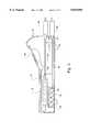
- FIG. 3is a cross-sectional view of an embodiment of the data collection device
- FIG. 4is a rear view of an embodiment of the data collection device
- FIG. 5is a top view of an embodiment of the data collection device
- FIG. 6is an electrical schematic of an embodiment of the data collection device
- FIGS. 7a, 7b and 7care flow charts of the computer program in an embodiment of the data collection device
- FIG. 8is an electrical schematic of another embodiment of the data collection device.
- FIGS. 9a, 9b and 9care flow charts of the computer program in the alternate embodiment of the data collection device.
- FIG. 1an embodiment of a portable data collection device 10 according to the present invention is depicted.
- the deviceis also discussed in copending U.S. patent application Ser. No. 08/269,240 for "Portable Data Colection Device” filed Jul. 1, 1994 now U.S. Pat. No. 5,537,855, incorporated herein by this reference in its entirety.
- the portable data collection device 10communicates information corresponding to sensed physical data to a digital computer as the portable data collection device 10 measures the sensed physical data from an experiment.
- the device 10includes a connection means 11 for operably coupling the device 10 to the digital computer 12.
- the digital computer 12can complement the operation of the portable data collection device 10 by performing various analytical functions, such as graphically displaying the information as a function of the time of measurement of the sensed physical data.
- FIG. 2illustrates a second mode of the portable data collection device 10 that is independent of the digital computer 12.
- the portable data collection device 10stores the information from the experiment in a memory means for later transmission to the digital computer 12.
- the portable data collection device 10can be used to monitor experiments at locations remote from the digital computer 12 and a power source.
- the portable data collection device 10should have a size and weight that is sufficient for the device 10 to be hand-held and portable by a user, such as a student.
- the device 10has a length less than about 8 inches, a width less than about 5 inches, and a height no more than about 3 inches.
- the device 10preferably weighs less than about 24 ounces.
- the hand-held size and portability of the portable data collection device 10makes it useful for the measurement of a wide variety of sensed physical data.
- the portable data collection device 10is especially useful for any application that involves sensed physical data measurement at locations remote from a digital computer, such as the monitoring of indoor and outdoor experiments or of selected parameters of a manufacturing or production process.
- the preferred application for the portable data collection device 10is for use by students at the secondary and post-secondary levels to measure sensed physical data.
- the portable data collection device 10uses a number of sensor means 14 that are interchangeable with a number of commonly configured and externally accessible input ports 16 in the device 10.
- Each sensor means 14has a commonly configured output port 15 that detachably connects to the input ports 16 in the device 10.
- the input ports 16preferably extend through the housing of the device 10 and have a portion that is externally accessible by the user.
- each sensor means 14can include (i) a sensing element 52 for measuring the sensed physical data; (ii) an interconnection means 53 for providing to the device 10 a sensed signal representative of sensed physical data; (iii) sensor circuitry 54 for connecting the sensing element 52 with the interconnection means 53; and (iv) a plug housing 62 to house the interconnection means 53.
- the interconnection means 53can include a scaling means 56 for altering the sensed signal 50a to correspond to preselected scaling factors in the device 10, a digital input means 57 to communicate sensed signals 50b to the device 10, a data identification means 58 for communicating to the device 10 a data identification signal 48 representative of the type of sensing element 52 and type of sensed physical data being measured by the sensing element 52, and a voltage regulator 60 to provide power to the sensing element 52.
- a scaling means 56for altering the sensed signal 50a to correspond to preselected scaling factors in the device 10
- a digital input means 57to communicate sensed signals 50b to the device 10
- a data identification means 58for communicating to the device 10
- a data identification signal 48representative of the type of sensing element 52 and type of sensed physical data being measured by the sensing element 52
- a voltage regulator 60to provide power to the sensing element 52.
- the sensor means 14provides enhanced user convenience by communicating to the device 10 not only the sensed signal 50 corresponding to sensed physical data but also the type of sensed physical data measured by each sensor means 14. In this manner, the device 10 is able to identify the type of sensor means 14 at each input port 16 without user input. The device 10 is further able to automatically identify the removal and/or replacement of sensor means 14 from an input port 16 by the user without user input.
- sensor means 14a, 14bthere are generally two configurations of sensor means 14a, 14b employed by the present invention.
- One type of sensor means 14ameasures sensed physical data that is not a function of time and the other type of sensor means 14b measures sensed physical data that is a function of time.
- the first type of sensor means 14acollects physical data such as the following: pH, pressure, temperature, magnetic field strength, electrical field strength, light intensity, viscosity, sound, humidity, composition, concentration, and other parameters that are not time-based.
- the second type of sensor means 14bcollects sensed physical data such as the following: velocity, acceleration, period and frequency of rotation, kinetic energy, period, and frequency, and other parameters that are time-based.
- the key difference between the two types of sensor means 14is the time dependency of the sensed physical data collected by the sensor means 14.
- the sensor means 14a, 14beach produce a sensed signal 50a, b that is representative of the sensed physical data being collected by the sensor means 14.
- a class that is a function of time and a class that is not a function of timetwo different types of sensed signals 50a, b are produced by the sensor means 14a, 14b.
- Sensed signal 50a from sensor means 14ais typically in analog form.
- Sensed signal 50bis typically in digital form.
- the sensed signal 50is generally an electrical impulse, such as voltage, resistance or current.
- the two classes of sensed physical dataare utilized to simplify the conversion by the microprocessor 36 of the sensed signals 50 to information and reduce the portion of the memory means 40 allocated for storage of the variables required to convert the sensed signals 50 to information.
- the device 10To convert each type of the sensed signals 50a, b to information corresponding to sensed physical data, the device 10 includes a first data set containing variables for converting the sensed signals 50a, b to information with the variables selected for a particular sensed signal 50 being based upon the data identification signal 48.
- the data identification signal 48is communicated by the sensor means 14 to the device 10 and is representative of the type of sensed physical data being measured by the sensor means 14.
- the variablescan be a preselected scaling factor for each type of sensed signal 50 and appropriate engineering units for the scaling factor.
- the scaling factoris preferably selected based upon the desired engineering units for expression of the information to the user and the strength of the sensed signal 50.
- the magnitude of the sensed signal 50ais preferably multiplied against the appropriate scaling factor for the type of sensed physical data represented by the sensed signal 50a.
- the duration of the sensed signal 50bis preferably multiplied against the appropriate scaling factor for the type of sensed physical data represented by the sensed signal 50b.
- either type of sensor means 14includes a sensing element 52 for providing the sensed signal 50 to the device 10.
- the sensing element 52is typically any device capable of measuring the desired type of sensed physical data. Such devices are generally of three types: resistive, ampometric, and voltaic.
- the circuitry and components of the sensing element 52depend on the type of sensed physical data to be measured.
- the sensing element 52can be a motion sensor to measure velocity, acceleration, and kinetic energy or a probe to measure the pH of a solution.
- the interconnection means 53a, 53bcommunicates the sensed signal 50 to the device 10 and provides the data identification signal 48 to the device 10 to identify the type of sensed physical data being measured by the sensing element 52 and therefore the type of sensing element 52 in the sensor means 14.
- the data identification means 58communicates the data identification signal 48 to the processor means 18 to enable the device 10 to identify the sensor means 14 at each input port 16.
- the data identification signal 48which is generally in analog form, indicates the type of sensed physical data that is represented by the sensed signal 50 and therefore the type of sensing element 52.
- the data identification signal 48enables the device 10 to identify the type of sensing element 52 in and the type of sensed physical data received from each sensor means 14 without input from the user.
- the data identification signal 48further enables the device 10 to identify the removal and/or replacement of a sensor means 14 by the user without user input.
- the data identification means 58is composed of one or more resistors in the portable data collection device 10 that are electrically connected in the interconnection means 53 to produce the desired magnitude of the data identification signal 48 for the specific type of sensing element 52 and sensed physical data to be measured by sensor means 14.
- the data identification signal 48 for a sensor means 14a that measures pHis a first voltage or temperature is a second voltage and for a sensor means 14b that measures velocity is a third voltage or kinetic energy is a fourth voltage.
- Each of the first, second, third, and fourth voltagesare different magnitudes.
- the voltage regulator 60 in the interconnection meanssupplies power to the sensing element 52.
- the interconnection means 53can include either the scaling means 56 for altering the sensed signals 50a to correspond to the preselected scaling factors in the first data set or the digital input means 57 to communicate sensed signals 50b to the digital input/output 46 for conversion into information.
- the scaling means 56preferably converts the magnitude of the sensed signal 50a to correspond to a preselected scaling factor for converting the sensed signal 50a into information.
- the scaling means 56is suitable electrical circuitry to adjust the magnitude of the sensed signal 50a to a level corresponding to the appropriate preselected scaling factor.
- the digital input means 57communicates sensed signal 50b to the digital input/output 46 for conversion of the sensed signal 50b into information by the device 10.
- the digital input means 57is any suitable circuitry for communicating a digital signal to the digital input/output 46. Because sensed signal 50b corresponds to a time-based measurement, the duration of the sensed signal 50b is typically related to the time period upon which the sensed physical data is based. For example, in a velocity measurement, the duration of the sensed signal 50b is related to the time an object requires to travel a selected distance.
- the plug housing 62contains the above-described elements of the interconnection means 53.
- the plug housing 62has an output port 15 that is configured to frictionally mate with the input ports 16.
- the output port 15is therefore detachable from the input ports 55.
- To frictionally mate with the various input ports 16, the output ports 15are generally commonly configured.
- the common configurationfacilitates the interchangeability of the various input ports 16 with the various output ports 15 of the sensor means 14.
- Sensor circuitry 54a, 54belectrically connects the sensing element 52a, 52b with the interconnection means 53a, 53b.
- the sensor circuitry 54is generally an electrical conductor, such as a wire, that is electrically compatible with the sensing element 52 and interconnection means 53.
- the portable data collection device 10includes a housing 34, a processor means 18 for controlling the input and output of information corresponding with the sensed physical data to and from a memory means 40 for storing the information, an interface assembly 20 to interface the sensor means 14 with the processor means 18, an operator control means 24 for controlling the processor means 18, a serial port 26, the input ports 16, a power outlet 28 and internal power source 30, and a power regulation circuit 32.
- the processor means 18controls the operation of the device 10 in response to user input through the operator control means 24.
- the processor means 18includes the memory means 40, a microprocessor 36, a chronometer 38, a backup power source 42, an analog-to-digital converter means 44 and a digital input/output 46.
- the memory means 40stores the information for access by the microprocessor 36.
- the memory means 40also stores the software to control the processor means 18 and the variables for converting sensed signals 50 into information.
- the memory means 40has volatile and non-volatile portions and random-access (RAM) and read-only (ROM) portions.
- the software and variablesare stored in a non-volatile ROM.
- Informationis stored in either volatile or non-volatile portions of RAM, depending on the amount of available memory space.
- the total memory capacityis at least 32K, with the volatile and non-volatile portions of the memory means, each being at least 16K and the ROM and RAM each being at least 16K.
- the microprocessor 36 in the processor means 18controls the operation of the portable data collection device 10 in response to user input through the operator control means 24 and the software in the memory means 40.
- the softwareis described below in reference to FIG. 7.
- the microprocessor 36includes at least one timer (not shown) for microsecond time measurements. The timer is typically used to measure the duration of sensed signal 50b.
- the chronometer 38enables the microprocessor 36 to index sensed physical data received by the microprocessor 36 as a function of the time and date that the sensed signal 50 was received by the microprocessor 36. Whereas the timer measures time in small increments, typically microseconds, the chronometer 38 measures time in larger increments, typically seconds, minutes, hours or days.
- the backup power source 42provides power to the non-volatile portion of the memory means 40 for preserving data stored in the memory means 40.
- the backup power source 42can be any suitable power source for the non-volatile portion of the memory means 40.
- the backup power source 42is one or more batteries.
- the analog-to-digital converter means 44receives the data identification signal 48 in analog form from each sensor means 14 and communicates the data identification signal 48 to the microprocessor 36.
- the analog-to-digital converter means 44can be any suitable analog-to-digital converter.
- the digital input/output 46receives the sensed signal 50b in digital form from each of the sensor means 14b.
- the digital input/output 46communicates the sensed signal 50b to the microprocessor 36 for conversion into sensed physical data.
- the portable data collection device 10further includes an interface assembly 20 to communicate the sensed signals 50a from the sensor means 14a to the processor means 18.
- the interface assembly 20includes a multiplexer means 64, a voltage protection means 66, and high resolution analog-to-digital converter means 68.
- the interface assembly 20is contained on printed circuit boards 70a,b mounted on supports 72a,b.
- the multiplexer means 64communicates, in response to a command received from the processor means 18, the sensed signals 50a received by the multiplexer means 64 from the sensor means 14a to the processor means 18. As discussed below, the processor means 18 communicates a command to the multiplexer means 64 for sensed signals 50a from sensor means 14a at a first selected time interval. In contrast, the sensed signals 50b from the sensor means 14b do not pass through the multiplexer means 64. The sensed signals 50b from the sensor means 14b are directly received by the processor means 18 via the digital input/output 46.
- the multiplexer means 64can be any suitable multiplexer.
- the channel capacity of the multiplexer means 64should at least equal the number of the input ports 16 configured to accommodate the sensor means 14a.
- the multiplexer means 64should have four dual channels for a portable data collection device 10 having four input ports 16 configured to accommodate the sensor means 14a.
- the voltage protection means 66is connected to the high resolution analog-to-digital converter means 68 and the multiplexer means 64 and adjusts the strength of the sensed signal 50a to fall within a predetermined sensed signal strength range to reduce the likelihood of the sensed signal 50a exceeding the electrical capacity of a component of the device 10.
- the circuitry of the voltage protection means 66depends upon the predetermined sensed signal strength range.
- the sensed signal strength rangeis dependent upon the electrical capacity of the processor means 18 and other electrical components of the portable data collection device 10.
- the high resolution analog-to-digital converter means 68converts the sensed signal 50a received from the voltage protection means 66 from analog to digital form.
- the high resolution analog-to-digital converter means 68preferably has a strength of at least about 16 bits.
- the high resolution analog-to-digital converter means 68provides for accurate sensed physical data measurements and allows for simple circuitry in the scaling means 56.
- the high bit strengthenables the high resolution analog-to-digital converter means 68 to convert to a digital form even sensed signals 50a that are of a low strength.
- the high resolution analog-to-digital converter means 68transmits the sensed signal 50a to the processor means 18.
- the input ports 16extend through the housing 34 to provide the externally accessible portion of the input port 16.
- the portion of the input port 16 inside the housing 34connects to the processor means 18 and (if appropriate) the multiplexer means 64.
- the externally accessible portion of the input port 16removably connects to the interconnection means 53.
- the input ports 16are typically commonly configured to facilitate the interchangeability of the input ports 16 with the various output ports 15.
- the number of input ports 16depends upon the number of sensor means 14 desired for the portable data collection device 10.
- the portable data collection device 10has at least 4 input ports 16.
- the various input ports 16are located in the housing 34 in the rear portion of the device 10. To facilitate ease of use by students and other types of users, the various input ports 16 are located in the rear portion of the housing 34 so as to be externally accessible by the user without removing a portion of the housing 34. This feature further protects the various components in the interior of the device 10 from damage caused by users, such as students, accessing the interior of the device 10.
- the various input ports 16are oriented in rows and columns. As shown in FIG. 4, at least two of the input ports 16 are offset from one another in both a horizontal and a vertical orientation.
- the input ports 16can include circuitry that interfaces with sensed signals 50 not only from the scaling means 56 but also from the digital input/output 57. All of the input ports 16 should have circuitry to communicate a sensed signal 50a from the scaling means 56 to the multiplexer means 64. At least one input port 16 should have circuitry to communicate a sensed signal 50b from the digital input means 57 to the digital input/output 46.
- the operator control means 24is operably connected to the processor means 18 to provide input from a user to the processor means 18.
- the operator control means 24has a plurality of individual keys for input.
- the individual keys in the operator control means 24provide different input to the processor means 18 depending upon whether the processor means 18 is in the data view mode (the default mode) or the menu mode. These two modes and the key commands in each mode are discussed in detail below.
- the serial port 26is operably connected to the processor means 18 for interfacing the portable data collection device 10 with the digital computer 12.
- the serial port 26operably couples to the digital computer 12 for communicating sensed physical data to the digital computer 12.
- the serial port 26not only communicates sensed physical data to the digital computer 12 but also receives commands from the digital computer 12 and communicates the commands to the processor means 18.
- the housing 34encloses the above-described components of the portable data collection device 10 to protect the components from damage.
- the housing 34generally has three sections that are interconnected: a top portion 34a, a bottom portion 34b, and a removable cover 82.
- the removable cover 82exposes the internal power source 30 for replacement.
- the device 10can include various other components.
- a presentation means 22can be connected to the processor means 18 for providing information to the user.
- the presentation means 22visually displays to the user information based on the sensed signals 50.
- the presentation means 22is preferably a liquid crystal display.
- the format of the presentation means 22is illustrated in FIG. 5.
- the presentation means 22visually presents information from each sensor means 14 with information displayed at a location on the presentation means 22 corresponding to the location of the sensor means 14 producing the information.
- the informationis oriented on the presentation means 22 relative to the location of the input port 16 that the sensor means 14 collecting the information is connected to.
- the information displayed in the upper right hand corner of the presentation means 22corresponds to a sensor means 14 connected to the upper right hand input port 16. If the sensor means 14 is moved to another input port 16, the presentation means 22 will alter the display to reflect the new sensor means 14 location.
- the information presented on the presentation means 22is the value measured by the sensor means 14 in scaled engineering units. For example, for a sensor means 14 measuring temperature the presentation means 22 would present the measured temperature in either degrees Fahrenheit or Celsius, as desired.
- the presentation means 22further presents two cursor signals to indicate (i) when the portable data collection device 10 is logging (e.g., storing) information in the memory and (ii) when the portable data collection device 10 is communicating information to a digital computer 12.
- a cursor signalis visible at the center position on the top line of the presentation means 22.
- a cursor signalis visible at the center position on the bottom line of the presentation means 22.
- the portable data collection device 10can include a power outlet 28 and internal power source 30.
- the power outlet 28plugs into an external power source.
- the internal power source 30is contained within the portable data collection device 10 in compartment 76.
- the internal power sourceis typically batteries.
- the internal power source 30permits the portable data collection device 10 to be transported to experimental locations remote from an external power source.
- a power regulation circuit 32can be connected to the power outlet 28 and internal power source 30 to maintain a desired power level to the portable data collection device 10.
- the power regulation circuit 32protects the various electrical components of the portable data collection device 10 against the destructive effects of power level fluctuations.
- the power regulation circuit 32maintains the voltage of the electrical power to the portable data collection device 10 at a desired level notwithstanding power level fluctuations. For example if the power outlet source 28 supplies power from an external power source to the portable data collection device 10, the power level may fluctuate in response to power surges or outages. If the internal power source 30 supplies power to the portable data collection device 10, the power level may decline during use as power is drained from the second power source 30.
- the data identification means 58communicates the data identification signal 48 to the analog-to-digital converter means 44 to inform the processor means 18 of the type of sensing element 52 and sensed physical data being collected by the sensing element 52 at each input port 16.
- the analog-to-digital converter means 44converts the data identification signal 48 from analog to digital form and communicates the data identification signal 48 to the microprocessor 36.
- the sensing element 52communicates a sensed signal 50a representative of the sensed physical data collected by the sensing element 52a to the scaling means 56.
- the scaling means 56alters the magnitude of the sensed signal 50a to a magnitude that corresponds to the particular scaling factor in the first data set for the type of sensed physical data represented by the sensed signal 50a.
- the scaling means 56then communicates the sensed signal 50a to the multiplexer means 64 in the interface assembly 20.
- the interface assembly 20receives and holds the sensed signals 50a from each sensor means 14a.
- the multiplexer means 64communicates the sensed signals 50a to the voltage protection means 66.
- the voltage protection means 66communicates the sensed signal 50a to the high resolution analog-to-digital converter means 68, which converts the sensed signal 50a from analog to digital form.
- the high resolution analog-to-digital converter means 68then communicates the sensed signal 50a to the processing means 18.
- the sensing element 52produces an electrical impulse based upon the motion of an object.
- the sensing element 52can include two light beams. When an object breaks the first light beam, a voltage is actuated in the sensor circuitry 54. When the object breaks the second light beam, the voltage in the sensor circuitry 54 is deactivated (e.g., a zero voltage exists in the sensor circuitry 54).
- the digital input means 57communicates the sensed signal 50b in digital form to the digital input/output 46 in the processor means 18.
- the timer(not shown) measures the duration of the sensed signal 50b which translates into a time period correlating to the sensed physical data.
- the sensed signal durationrepresents the time period required by the object to travel the distance between the two light beams. This data may be used to determine physical data values such as the velocity of the object.
- other configurations of sensing element 52may be used to collect physical data that is a function of time.
- FIG. 7illustrates a flow chart for the program that controls the operation of the processor means 18.
- the microprocessor 36loads the program when the device 10 is activated.
- the microprocessor 36 in box 90initializes variables for scaling the sensed signals from each sensor means 14 and loads the first data set from a non-volatile portion of the memory means 40.
- the first data setcontains scaling factors and appropriate engineering units indexed by the differing magnitudes of the data identification signals 48 emitted by the various types of sensor means 14.
- the microprocessor 36 in box 94compares the magnitude of the data identification signals 48 received from each of the sensor means 14 against the first data set to identify the type of sensor means 14 at each input port 16.
- the microprocessor 36selects the appropriate variables for each of the sensor means 14 from the first data set and loads the variables and location of each sensor means 14 into a second data set. To obtain the measured value of the physical data, the appropriate variables are applied to the magnitude or duration of the sensed signal 50 to yield the information.
- the microprocessor 36 in box 98initializes the channel specifics and determines background voltage in the circuitry of the portable data collection device 10. The background voltage is subtracted from the strengths of the sensed and data identification signals 50, 48 to provide a more accurate determination of the sensed physical data values.
- the microprocessor 36 in box 102initializes the system timing interrupt by selecting a first selected time interval based on second and third selected time intervals.
- the second selected time intervalis a default variable governing the time interval during which the microprocessor 36 communicates to the presentation means 22 information based upon the sensed signal 50a.
- the second selected time intervalranges from about 0.75 to about 1.5 seconds.
- the third selected time intervalis selected by the user and governs the time interval during which the microprocessor 36 communicates information to the memory means 40 for later transmission to the digital computer 12 or to the digital computer 12 as received by the processor means 18.
- the third selected intervalranges from about 2 seconds to several hours.
- the default value of the third selected time intervalis about 2 seconds.
- the microprocessor 36communicates a command for sensed signals 50a to the multiplexer means 64 after the first selected time interval expires.
- the first selected time intervalwill be equivalent to the lesser of the second and third selected time intervals.
- the second and third selected time intervalsare generally multiples of one another.
- the microprocessor 36initializes the interrupt handler for the operator control means 24.
- the interrupt handlernotifies the microprocessor 36 when a user provides input to the operator control means 24 (e.g., a key is pressed).
- the microprocessor 36 in box 106initializes the presentation means 22 by selecting the proper character sets, and other variables of the presentation means 22.
- the microprocessor 36is idle until the first time interval expires. At the expiration of the first time interval, the microprocessor 36 either provides information to the presentation means 22 or computes information for storage in the memory means 40 for communication to a digital computer 12. The function to be performed by the microprocessor 36 depends on whether the second or third time interval expired.
- the microprocessor 36determines if a key was pressed and, if so, identifies in box 118 the mode.
- the identities of the keysdepend upon whether the menu or data view modes are selected by the user.
- the microprocessor 36 in box 122prompts the user to communicate or download the information stored in the memory means 40 to the digital computer 12.
- the userresponds to the prompt by either pressing the "Yes” or “No” keys. If “Yes” is pressed, the information in the memory means 40 is downloaded to the digital computer 12.
- the microprocessor 36 in box 126prompts the user to clear the RAM portion of the memory means 40.
- the userresponds by either pressing the "Yes” or “No” keys. If “Yes” is pressed, the stored sensed physical data is cleared from the memory means 40.
- the microprocessor 36 in box 130displays the third selected time interval and the remaining capacity of the memory means 40 based on the third selected time interval.
- the usermay adjust the third selected time interval either upward or downward by pressing the "Up” or “Down” keys.
- the "OK” keyreturns the microprocessor to the data view mode.
- the presentation means 22presents the information for the user unless the user presses the "Log On/Off” or "Computer Monitor On/Off” keys.
- the microprocessor 36communicates information to the memory means 40. A cursor then appears on the display 22 as described above.
- the microprocessor 36stops communicating information to the memory means 40 when the "Log On/Off” key is pressed a second time.
- the microprocessor 36communicates to the digital computer 12 information as it is received by the microprocessor 36 from the sensor means 14. A cursor then appears on the presentation means 22 as described above.
- the microprocessor 36stops communicating information to the digital computer 12 when the "Computer Monitor on/Off" key is pressed a second time.
- the usermay select either the menu mode while in the data view mode or the data view mode while in the menu mode by depressing the "Menu" and "View” keys, respectively.
- the microprocessor 36determines if any sensor means 14 was replaced or removed. If a sensor means 14 was replaced at or removed from an input port 16, the microprocessor 36 in box 146 determines the type of sensor means 14 at the input port 16 based upon the data identification signal 48. The microprocessor 36 then loads the appropriate variables for the new sensor means 14 (e.g., scaling factors and engineering units) from the first data set into the second data set.
- the appropriate variables for the new sensor means 14e.g., scaling factors and engineering units
- the microprocessor 36determines if the first selected time interval has expired. When the first selected time interval expires, the microprocessor 36 in box 154 communicates a command to the multiplexer means 64 for the sensed signals 50a. The command is repeated until the sensed signals 50a are received from each of the sensor means 14a.
- the microprocessor 36applies the appropriate variables to each of the sensed signals 50 to acquire the information.
- the microprocessor 36determines based on user input from the operator control means 24 in box 138 whether the information is to be communicated to the digital computer 12.
- the microprocessor 36 in box 166communicates the information to the digital computer 12, as appropriate.
- the microprocessor 36determines, based on the third selected time interval and user input from the operator control means 24 in box 122, whether information is to be logged or stored in RAM. In box 174, the microprocessor 36 communicates the information to the memory means 40, as appropriate.
- the microprocessor 36determines, based on the second selected time interval, whether the information is to be communicated to the presentation means 22.
- the microprocessor 36communicates in box 182 the information to the presentation means 22, as appropriate.
- the microprocessor 36After determining whether to communicate the information to the presentation means 22 in box 182, the microprocessor 36 returns to box 110 in the flow chart to repeat the steps described above after an interrupt command is received by the microprocessor 36.
- the data identification means 204includes a sensor memory means (not shown).
- the data identification means 58 in each sensor means 14communicated a data identification signal 48 in analog form to the processor means 18, which would apply the proper scaling factor(s) stored in the memory means 40 to the sensed signal 50 received from the sensor means 14 to provide sensed physical data. This process is called calibration.
- the present embodimentprovides sensor information stored in the sensor memory means in the data identification means 204 to the processor means 18.
- the data identification signal 208is represented by the sensor information and is in digital, not analog, form.
- the sensor informationincludes calibration information.
- the calibration informationincludes not only a calibration equation identifier for selection of a calibration equation stored in the memory means 40 but also values for the unknown calibration constants in the calibration equation.
- the appropriate calibration equationprovides the scaling factor used to convert the sensed signals 50 into sensed physical data.
- the sensor memory meansis preferably an EEPROM.
- the EEPROMis an electrically erasable memory chip which does not lose information when the sensor memory means loses power. Thus, the EEPROM does not require a back-up power source.
- the EEPROMpreferably has a memory capacity of 256 bytes.
- the sensor memory meansstores a variety of sensor information connected with the operation of the sensor means 200.
- the sensor informationincludes not only the calibration information referred to above but also a sensor identifier of the specific sensor means 200 (e.g., a type of serial number).
- the sensor identifier in the sensor informationis different for each and every sensor means 200.
- the sensor identifiercan, but is not required to, indicate the type of sensed physical data collected by a sensor means 200.
- the sensor identifiercan be logged by the processor means 18 along with the sensed physical data collected by the sensor means 200. This provides the ability to index sensed physical data by the sensor identifier which enables a user to identify at a later time the specific sensor means 200 providing the sensed physical data. This capability is advantageous for verifying the accuracy of sensed physical data after collection. By way of example, if a sensor means 200 is or becomes defective, a user can determine what sensed physical data was collected by the sensor means 200, even if a number of different sensor means 200 were employed to collect the sensed physical data.
- the sensor memory meansalso provides calibration information to the processor means 18 for calibration of the sensed physical data.
- the calibration informationcan include: (i) the appropriate units to display the sensed physical data (e.g., "pH”, "m/s", “°F.”, and the like); (ii) format information specifying the format to be used by the presentation means 22 to display the sensed physical data; (iii) the designation of the appropriate calibration equation to be used by the processor means 18 during calibration (e.g., the calibration equation identifier); and (iv) the values of the calibration constants used in the calibration equation.
- the formatis based upon the number of characters available on the presentation means 22 for display of the sensed physical data.
- the decimal pointmust be correctly located to display as much information as possible (e.g., "7.026 pH”, “150.1° F.”, and "34.1 m/s").
- the format informationis conveyed to the processor means 18 by means of a number denoting which display format of the several possible display formats in the memory means 40 is to be used for the presentation means 22.
- the designation of the appropriate calibration equation and the values of the calibration constants for the calibration equationare stored in the sensor memory means while a set of calibration equations is stored in the memory means 40.
- the calibration equationscorrespond to specific curve configurations. There is a finite number of calibration equations or curve configurations required for calibration of all of the sensor means 200. Each type of sensor means 200 will use one of the calibration equations or curve configurations.
- the information respectively stored in the memory means 40 and the sensor memory meansis as follows:
- a sensor memory meanswill typically store only one data set of an equation number and the corresponding calibration constants.
- the sensor memory meanswill not typically store the calibration constants for a number of different calibration equations. Only one calibration equation generally applies to a given sensor means 200.
- the storing of the calibration equations in the memory means 40 and the appropriate calibration equation number and calibration constants in the sensor memory meanspermits "new" sensor means 200 to be developed and connected to the device without changes to the device, including the software in the device. This feature renders the device extremely versatile. This is particularly advantageous in educational applications where numbers of different types of sensed physical data are required to be collected.
- the calibration information in the sensor memory meanscan be altered by the user with the altered calibration information being stored in the sensor memory means.
- the altered calibration informationreplaces a default set of calibration information in the sensor memory means.
- the altered calibration informationis stored in the sensor memory means separately from the default calibration information.
- the userpreferably is unable to alter only the default calibration information. This feature permits a user to modify the calibration information for more precise calibration of the sensed signals, to display the sensed physical data in different units and/or a different format, to take into consideration changes in the performance of the sensor means 200 over time, and to be taught about calibration and calibration techniques in educational applications.
- the ability for a user to alter the calibration informationincreases the accuracy of the sensed physical data relative to prior art data logging devices.
- the featurepermits a specific sensor means for collecting a specific type of sensed physical data to be calibrated differently from another sensor means 200 for collecting the same type of sensed physical data. As will be appreciated, there will almost always be slight variations in the performance of different sensor means 200 for collecting the same type of sensed physical data. User calibration permits these variations to be taken into account.
- the calibration information in the sensor memory meansis accessed by the processor means 18 for retrieval. This feature permits the processor means 18 to recognize a sensor means 200 automatically without user input. This is especially useful where the device has a plurality of interchangeable sensor means types.
- the sensor means 200typically does not include a microprocessor and/or an analog-to-digital converter. Placing a microprocessor and/or an analog-to-digital converter in each sensor means would significantly increase costs. The use of the processing means 18 in the device to service all of the sensor means 200 represents a significant cost savings in data logging.
- the operation of the computer program in the data collection devicewill be described as it relates to the information in the sensor memory means.
- the computer programis the same as that in FIG. 7 with the exception of the following differences.
- the microprocessor 36simply initializes variables and does not load the first data set from the memory means 40.
- the information in the first data set in the previous embodimentis substantially the same information as that contained in the sensor information in the sensor memory means.
- the microprocessor 36loads the sensor information in the sensor memory means into the microprocessor 36 and the appropriate calibration equation from the memory means 40 into the microprocessor 36.
- the previous embodimentread the sensor means types and loaded the appropriate variables from the first data set into the second data set.
- box 146the same explanation for box 90 also applies to box 146.
- FIG. 9further includes box nos. 139 and 140 which are not in FIG. 7.
- the microprocessor 36prompts the user to re-set the time and date of collection of the sensed physical data.
- the microprocessor 36prompts the user to alter the calibration information as described above.
Landscapes
- Physics & Mathematics (AREA)
- General Physics & Mathematics (AREA)
- Engineering & Computer Science (AREA)
- Technology Law (AREA)
- Arrangements For Transmission Of Measured Signals (AREA)
Abstract
Description
______________________________________ Information in Sensor Memory Means Information in Memory Means Equation Calibration Equation Number Constant Number Calibration Equation ______________________________________ "1" A.sub.1, B.sub.1 "1" Y = A.sub.1 X + B.sub.1 "2" A.sub.2, B.sub.2, C.sub.2 "2" Y = A.sub.2 X.sup.2 + B.sub.2 X + C.sub.2 "3" A.sub.3, B.sub.3, C.sub.3, D.sub.3 "3" Y = A.sub.3 X.sup.3 + B.sub.3 X.sup.2 + C.sub.3 X + D.sub.3 . . . . . . "n" A.sub.n, B.sub.n, C.sub.n "n" Y = A.sub.n e.sup.(B.spsb.n.sup.X.spsp.Cn.sup.)______________________________________
Claims (23)
Priority Applications (1)
| Application Number | Priority Date | Filing Date | Title |
|---|---|---|---|
| US08/750,136US5839094A (en) | 1995-06-30 | 1995-06-30 | Portable data collection device with self identifying probe |
Applications Claiming Priority (2)
| Application Number | Priority Date | Filing Date | Title |
|---|---|---|---|
| PCT/US1995/008308WO1996001411A1 (en) | 1994-07-01 | 1995-06-30 | Portable data collection device |
| US08/750,136US5839094A (en) | 1995-06-30 | 1995-06-30 | Portable data collection device with self identifying probe |
Publications (1)
| Publication Number | Publication Date |
|---|---|
| US5839094Atrue US5839094A (en) | 1998-11-17 |
Family
ID=25016654
Family Applications (1)
| Application Number | Title | Priority Date | Filing Date |
|---|---|---|---|
| US08/750,136Expired - LifetimeUS5839094A (en) | 1995-06-30 | 1995-06-30 | Portable data collection device with self identifying probe |
Country Status (1)
| Country | Link |
|---|---|
| US (1) | US5839094A (en) |
Cited By (64)
| Publication number | Priority date | Publication date | Assignee | Title |
|---|---|---|---|---|
| US5963726A (en)* | 1998-03-20 | 1999-10-05 | National Instruments Corporation | Instrumentation system and method including an improved driver software architecture |
| US6085156A (en)* | 1998-03-20 | 2000-07-04 | National Instruments Corporation | Instrumentation system and method having instrument interchangeability |
| US6141625A (en)* | 1997-06-09 | 2000-10-31 | Dickey-John Corporation | Viscometer module with crystal resonator-type sensor |
| US6246966B1 (en)* | 1998-04-06 | 2001-06-12 | Bayer Corporation | Method and apparatus for data management authentication in a clinical analyzer |
| US6321171B1 (en)* | 1998-04-03 | 2001-11-20 | Tektronix, Inc. | Electronic measurement instrument probe accessory offset, gain, and linearity correction method |
| US6360179B1 (en)* | 2000-02-18 | 2002-03-19 | Milestone Technology, Inc. | Systems, methods and apparatus for wireless transmission and reception of data by agricultural field sensors |
| FR2821423A1 (en)* | 2001-02-23 | 2002-08-30 | France Etat Ponts Chaussees | SYSTEM AND METHOD FOR MEASURING AND RECORDING EVENTS ALONG A ROUTE |
| US20030006989A1 (en)* | 2001-07-06 | 2003-01-09 | Michael Konrad | Field device with display |
| US6533723B1 (en)* | 2000-08-25 | 2003-03-18 | Ge Marquette Medical Systems, Inc. | Multiple-link cable management apparatus |
| US6539341B1 (en)* | 2000-11-06 | 2003-03-25 | 3Com Corporation | Method and apparatus for log information management and reporting |
| US20030135547A1 (en)* | 2001-07-23 | 2003-07-17 | Kent J. Thomas | Extensible modular communication executive with active message queue and intelligent message pre-validation |
| US6597990B2 (en) | 1997-02-13 | 2003-07-22 | Anthony Brown | Severe weather detector and alarm |
| US6691068B1 (en)* | 2000-08-22 | 2004-02-10 | Onwafer Technologies, Inc. | Methods and apparatus for obtaining data for process operation, optimization, monitoring, and control |
| US20040092801A1 (en)* | 2002-11-13 | 2004-05-13 | Budimir Drakulic | System for, and method of, acquiring physiological signals of a patient |
| US6747692B2 (en) | 1997-03-28 | 2004-06-08 | Symbol Technologies, Inc. | Portable multipurpose recording terminal and portable network server |
| EP1450137A1 (en)* | 2003-02-19 | 2004-08-25 | Alstom Technology Ltd | Measurement unit |
| US6789030B1 (en) | 2000-06-23 | 2004-09-07 | Bently Nevada, Llc | Portable data collector and analyzer: apparatus and method |
| US20050016276A1 (en)* | 2003-06-06 | 2005-01-27 | Palo Alto Sensor Technology Innovation | Frequency encoding of resonant mass sensors |
| US6935566B1 (en) | 1997-02-03 | 2005-08-30 | Symbol Technologies, Inc. | Portable instrument for electro-optically reading indicia and for projecting a bit-mapped image |
| US7114388B1 (en) | 2003-04-21 | 2006-10-03 | Ada Technologies, Inc. | Geographically distributed environmental sensor system |
| US20060235741A1 (en)* | 2005-04-18 | 2006-10-19 | Dataforensics, Llc | Systems and methods for monitoring and reporting |
| US20060290488A1 (en)* | 2005-05-27 | 2006-12-28 | Bionime Corporation | Coding module and sensing meter and system therefor |
| US20070265715A1 (en)* | 2004-04-26 | 2007-11-15 | Benoit Chouinard | Method for Permanent Calibration Based on Actual Measurement |
| US20070264620A1 (en)* | 2006-02-24 | 2007-11-15 | Toyota Motor Engineering & Manufacturing North America, Inc. | Testing systems and methods using manufacturing simulations |
| WO2007131729A1 (en)* | 2006-05-12 | 2007-11-22 | Ksb Aktiengesellschaft | Device for transmitting measured values |
| US20080111680A1 (en)* | 2006-11-14 | 2008-05-15 | Harris Corporation | Automatic discovery and classification of detectors used in unattended ground sensor systems |
| CH697590B1 (en)* | 2003-03-12 | 2008-12-15 | Alstom Technology Ltd | Measurement unit, e.g. for use in process automation, process control and automation systems, comprises a local processor and storage to enable local processing of measurement data before transfer to a central unit |
| US7484887B2 (en)* | 2003-02-20 | 2009-02-03 | Ysis Incorporated | Digitally modified resistive output for a temperature sensor |
| US20090217755A1 (en)* | 2008-02-29 | 2009-09-03 | Omega Engineering, Inc. | Smart sensor |
| US20090320143A1 (en)* | 2008-06-24 | 2009-12-24 | Microsoft Corporation | Sensor interface |
| US7739361B2 (en) | 1996-08-20 | 2010-06-15 | Thibault Richard L | Methods for remote process control with networked digital data processors and a virtual machine environment |
| US20100198867A1 (en)* | 1998-10-19 | 2010-08-05 | Sony Corporation | Information processing apparatus and method, information processing system, and providing medium |
| US20100240991A1 (en)* | 2006-07-07 | 2010-09-23 | Signostics Pty Ltd | medical interface |
| US8028272B2 (en) | 1999-05-17 | 2011-09-27 | Invensys Systems, Inc. | Control system configurator and methods with edit selection |
| US8090452B2 (en) | 1999-06-11 | 2012-01-03 | Invensys Systems, Inc. | Methods and apparatus for control using control devices that provide a virtual machine environment and that communicate via an IP network |
| US8127060B2 (en) | 2009-05-29 | 2012-02-28 | Invensys Systems, Inc | Methods and apparatus for control configuration with control objects that are fieldbus protocol-aware |
| US8275313B1 (en) | 2007-01-15 | 2012-09-25 | Advanced Distributed Sensor Systems | Long range, low power, mesh networking without concurrent timing |
| US8368640B2 (en) | 1999-05-17 | 2013-02-05 | Invensys Systems, Inc. | Process control configuration system with connection validation and configuration |
| US8463964B2 (en) | 2009-05-29 | 2013-06-11 | Invensys Systems, Inc. | Methods and apparatus for control configuration with enhanced change-tracking |
| US8543345B1 (en)* | 2008-08-04 | 2013-09-24 | Ada Technologies, Inc. | Electrochemical potentiostat employing smart electrodes |
| EP2148177A3 (en)* | 2008-07-10 | 2013-11-13 | AVL List GmbH | Measuring assembly and method for measuring variables |
| US8594814B2 (en) | 2008-06-20 | 2013-11-26 | Invensys Systems, Inc. | Systems and methods for immersive interaction with actual and/or simulated facilities for process, environmental and industrial control |
| US8964338B2 (en) | 2012-01-11 | 2015-02-24 | Emerson Climate Technologies, Inc. | System and method for compressor motor protection |
| US8974573B2 (en) | 2004-08-11 | 2015-03-10 | Emerson Climate Technologies, Inc. | Method and apparatus for monitoring a refrigeration-cycle system |
| US9121407B2 (en) | 2004-04-27 | 2015-09-01 | Emerson Climate Technologies, Inc. | Compressor diagnostic and protection system and method |
| US9140728B2 (en) | 2007-11-02 | 2015-09-22 | Emerson Climate Technologies, Inc. | Compressor sensor module |
| WO2015150671A1 (en)* | 2014-04-01 | 2015-10-08 | Socomec | Device for measuring at least one physical quantity of an electric installation |
| EP2963557A1 (en)* | 2014-07-01 | 2016-01-06 | Axis AB | Methods and devices for finding settings to be used in relation to a sensor unit connected to a processing unit |
| US9285802B2 (en) | 2011-02-28 | 2016-03-15 | Emerson Electric Co. | Residential solutions HVAC monitoring and diagnosis |
| US9310439B2 (en) | 2012-09-25 | 2016-04-12 | Emerson Climate Technologies, Inc. | Compressor having a control and diagnostic module |
| US9310094B2 (en) | 2007-07-30 | 2016-04-12 | Emerson Climate Technologies, Inc. | Portable method and apparatus for monitoring refrigerant-cycle systems |
| US9319668B2 (en) | 2012-11-29 | 2016-04-19 | Axis Ab | Method and system for generating real-time motion video |
| US9551504B2 (en) | 2013-03-15 | 2017-01-24 | Emerson Electric Co. | HVAC system remote monitoring and diagnosis |
| US9638436B2 (en) | 2013-03-15 | 2017-05-02 | Emerson Electric Co. | HVAC system remote monitoring and diagnosis |
| KR20170076154A (en)* | 2015-12-24 | 2017-07-04 | 삼성전자주식회사 | Electronic apparatus and control method thereof |
| US9719918B2 (en) | 2012-10-11 | 2017-08-01 | Endress + Hauser Gmbh + Co. Kg | Apparatus and system for determining, optimizing or monitoring at least one process variable |
| US9741023B2 (en) | 2012-02-28 | 2017-08-22 | Emerson Electric Co. | HVAC system remote monitoring and diagnosis |
| US9765979B2 (en) | 2013-04-05 | 2017-09-19 | Emerson Climate Technologies, Inc. | Heat-pump system with refrigerant charge diagnostics |
| US9803902B2 (en) | 2013-03-15 | 2017-10-31 | Emerson Climate Technologies, Inc. | System for refrigerant charge verification using two condenser coil temperatures |
| US9823632B2 (en) | 2006-09-07 | 2017-11-21 | Emerson Climate Technologies, Inc. | Compressor data module |
| US9885507B2 (en) | 2006-07-19 | 2018-02-06 | Emerson Climate Technologies, Inc. | Protection and diagnostic module for a refrigeration system |
| US20180163991A1 (en)* | 2016-12-13 | 2018-06-14 | Haier Us Appliance Solutions, Inc. | Water Heater Appliance |
| US10152551B2 (en) | 2014-05-28 | 2018-12-11 | Axis Ab | Calibration data in a sensor system |
| US10929565B2 (en) | 2001-06-27 | 2021-02-23 | Sony Corporation | Integrated circuit device, information processing apparatus, memory management method for information storage device, mobile terminal apparatus, semiconductor integrated circuit device, and communication method using mobile terminal apparatus |
Citations (21)
| Publication number | Priority date | Publication date | Assignee | Title |
|---|---|---|---|---|
| US4360345A (en)* | 1980-07-14 | 1982-11-23 | American Heart Association, Inc. | Health education system |
| US4530069A (en)* | 1982-08-20 | 1985-07-16 | Universal Data, Inc. | Expandable data communication system utilizing hand-held terminal |
| US4654818A (en)* | 1983-12-16 | 1987-03-31 | Texas Instruments Incorporated | Data processing device having memory selectively interfacing with computer |
| US4695955A (en)* | 1983-12-26 | 1987-09-22 | A2F | Electronic device providing a universal interface between sensors and an acquisition and processing unit of the signals originating from said sensors |
| US4715385A (en)* | 1986-09-26 | 1987-12-29 | Marquette Electronics, Inc. | Patient monitoring system having transportable data module and display unit |
| US4730247A (en)* | 1983-09-05 | 1988-03-08 | Mitutoyo Mfg. Co., Ltd. | Digital indication type measuring apparatus and measured data storage apparatus therefor |
| US4758963A (en)* | 1982-09-14 | 1988-07-19 | Analogic Corporation | Modular computing oscilloscope with high speed signal memory |
| US4811249A (en)* | 1985-02-15 | 1989-03-07 | Delta Technical Services, Limited | Data loggers |
| US4885707A (en)* | 1987-02-19 | 1989-12-05 | Dli Corporation | Vibration data collecting and processing apparatus and method |
| US4895161A (en)* | 1986-09-26 | 1990-01-23 | Marquette Electronics | Transportable data module and display unit for patient monitoring system |
| US4916441A (en)* | 1988-09-19 | 1990-04-10 | Clinicom Incorporated | Portable handheld terminal |
| US4924418A (en)* | 1988-02-10 | 1990-05-08 | Dickey-John Corporation | Universal monitor |
| US5008843A (en)* | 1987-12-23 | 1991-04-16 | Dr. Ing. H.C.F. Porsche Ag | Sensor having an answerback device |
| US5089979A (en)* | 1989-02-08 | 1992-02-18 | Basic Measuring Instruments | Apparatus for digital calibration of detachable transducers |
| US5099437A (en)* | 1990-10-09 | 1992-03-24 | Fugitive Emissions Control, Inc. | Emissions monitoring and tracking system |
| US5202817A (en)* | 1989-06-07 | 1993-04-13 | Norand Corporation | Hand-held data capture system with interchangeable modules |
| US5206818A (en)* | 1991-09-19 | 1993-04-27 | International Business Machines Corporation | Fugitive emissions monitoring system including integrated fugitive emissions analyzer and source identifier |
| US5227988A (en)* | 1989-11-09 | 1993-07-13 | Nippon Steel Corporation | Apparatus for detecting various process values and apparatus for recording information |
| US5249863A (en)* | 1992-02-14 | 1993-10-05 | Texaco Inc. | Temperature averaging data logger |
| US5347476A (en)* | 1992-11-25 | 1994-09-13 | Mcbean Sr Ronald V | Instrumentation system with multiple sensor modules |
| US5375604A (en)* | 1992-12-11 | 1994-12-27 | Siemens Medical Electronics, Inc. | Transportable modular patient monitor |
- 1995
- 1995-06-30USUS08/750,136patent/US5839094A/ennot_activeExpired - Lifetime
Patent Citations (22)
| Publication number | Priority date | Publication date | Assignee | Title |
|---|---|---|---|---|
| US4360345A (en)* | 1980-07-14 | 1982-11-23 | American Heart Association, Inc. | Health education system |
| US4530069A (en)* | 1982-08-20 | 1985-07-16 | Universal Data, Inc. | Expandable data communication system utilizing hand-held terminal |
| US4758963A (en)* | 1982-09-14 | 1988-07-19 | Analogic Corporation | Modular computing oscilloscope with high speed signal memory |
| US4730247A (en)* | 1983-09-05 | 1988-03-08 | Mitutoyo Mfg. Co., Ltd. | Digital indication type measuring apparatus and measured data storage apparatus therefor |
| US4654818A (en)* | 1983-12-16 | 1987-03-31 | Texas Instruments Incorporated | Data processing device having memory selectively interfacing with computer |
| US4695955A (en)* | 1983-12-26 | 1987-09-22 | A2F | Electronic device providing a universal interface between sensors and an acquisition and processing unit of the signals originating from said sensors |
| US4811249A (en)* | 1985-02-15 | 1989-03-07 | Delta Technical Services, Limited | Data loggers |
| US4715385A (en)* | 1986-09-26 | 1987-12-29 | Marquette Electronics, Inc. | Patient monitoring system having transportable data module and display unit |
| US4895161A (en)* | 1986-09-26 | 1990-01-23 | Marquette Electronics | Transportable data module and display unit for patient monitoring system |
| US4885707A (en)* | 1987-02-19 | 1989-12-05 | Dli Corporation | Vibration data collecting and processing apparatus and method |
| US5008843A (en)* | 1987-12-23 | 1991-04-16 | Dr. Ing. H.C.F. Porsche Ag | Sensor having an answerback device |
| US4924418A (en)* | 1988-02-10 | 1990-05-08 | Dickey-John Corporation | Universal monitor |
| US4916441A (en)* | 1988-09-19 | 1990-04-10 | Clinicom Incorporated | Portable handheld terminal |
| US5089979A (en)* | 1989-02-08 | 1992-02-18 | Basic Measuring Instruments | Apparatus for digital calibration of detachable transducers |
| US5202817A (en)* | 1989-06-07 | 1993-04-13 | Norand Corporation | Hand-held data capture system with interchangeable modules |
| US5227988A (en)* | 1989-11-09 | 1993-07-13 | Nippon Steel Corporation | Apparatus for detecting various process values and apparatus for recording information |
| US5099437A (en)* | 1990-10-09 | 1992-03-24 | Fugitive Emissions Control, Inc. | Emissions monitoring and tracking system |
| US5225996A (en)* | 1990-10-09 | 1993-07-06 | Fugitive Emissions Control, Inc. | Emissions monitoring and tracking system |
| US5206818A (en)* | 1991-09-19 | 1993-04-27 | International Business Machines Corporation | Fugitive emissions monitoring system including integrated fugitive emissions analyzer and source identifier |
| US5249863A (en)* | 1992-02-14 | 1993-10-05 | Texaco Inc. | Temperature averaging data logger |
| US5347476A (en)* | 1992-11-25 | 1994-09-13 | Mcbean Sr Ronald V | Instrumentation system with multiple sensor modules |
| US5375604A (en)* | 1992-12-11 | 1994-12-27 | Siemens Medical Electronics, Inc. | Transportable modular patient monitor |
Non-Patent Citations (8)
| Title |
|---|
| DOE Abstract for DOE Grant No. DE FG02 93ER81585, Nov. 1992.* |
| DOE Abstract for DOE Grant No. DE-FG02-93ER81585, Nov. 1992. |
| Omegg Entineering Sales Literature for Portable dataloggers, pp. F 83 to F 90 & F 97, Dec. 1991.* |
| Omegg Entineering Sales Literature for Portable dataloggers, pp. F-83 to F-90 & F-97, Dec. 1991. |
| Sales Literature, Micro Data Logger, Dec. 1993.* |
| Sales Literature, Philip Harris, Dec. 1992.* |
| Sales Literature, Rustrak Ranger II Data Logger, Jul. 1990.* |
| Sales Literature, Texas Instruments, Jan. 1994.* |
Cited By (135)
| Publication number | Priority date | Publication date | Assignee | Title |
|---|---|---|---|---|
| US7739361B2 (en) | 1996-08-20 | 2010-06-15 | Thibault Richard L | Methods for remote process control with networked digital data processors and a virtual machine environment |
| US7882197B2 (en) | 1996-08-20 | 2011-02-01 | Invensys Systems, Inc. | Control system methods that transfer control apparatus information over IP networks in web page-less transfers |
| US7899070B2 (en) | 1996-08-20 | 2011-03-01 | Invensys Systems, Inc. | Control system apparatus with change updates |
| US7979488B2 (en) | 1996-08-20 | 2011-07-12 | Invensys Systems, Inc. | Control system methods using value-based transfers |
| US8023500B2 (en) | 1996-08-20 | 2011-09-20 | Invensys Systems, Inc. | Methods for process control with change updates |
| US8081584B2 (en) | 1996-08-20 | 2011-12-20 | Invensys Systems, Inc. | Control system apparatus and systems using value-based transfers |
| US6935566B1 (en) | 1997-02-03 | 2005-08-30 | Symbol Technologies, Inc. | Portable instrument for electro-optically reading indicia and for projecting a bit-mapped image |
| USRE43903E1 (en) | 1997-02-13 | 2013-01-01 | Richmond Ip Holdings, Llc | Severe weather detector and alarm |
| USRE45514E1 (en) | 1997-02-13 | 2015-05-12 | La Crosse Technology Ip Holdings, Llc | Severe weather detector and alarm |
| US6597990B2 (en) | 1997-02-13 | 2003-07-22 | Anthony Brown | Severe weather detector and alarm |
| US6747692B2 (en) | 1997-03-28 | 2004-06-08 | Symbol Technologies, Inc. | Portable multipurpose recording terminal and portable network server |
| US6141625A (en)* | 1997-06-09 | 2000-10-31 | Dickey-John Corporation | Viscometer module with crystal resonator-type sensor |
| US5963726A (en)* | 1998-03-20 | 1999-10-05 | National Instruments Corporation | Instrumentation system and method including an improved driver software architecture |
| US6223134B1 (en)* | 1998-03-20 | 2001-04-24 | National Instruments Corporation | Instrumentation system and method including an improved driver software architecture |
| US6085156A (en)* | 1998-03-20 | 2000-07-04 | National Instruments Corporation | Instrumentation system and method having instrument interchangeability |
| US6321171B1 (en)* | 1998-04-03 | 2001-11-20 | Tektronix, Inc. | Electronic measurement instrument probe accessory offset, gain, and linearity correction method |
| US6246966B1 (en)* | 1998-04-06 | 2001-06-12 | Bayer Corporation | Method and apparatus for data management authentication in a clinical analyzer |
| US9575556B2 (en)* | 1998-10-19 | 2017-02-21 | Sony Corporation | Information processing apparatus and method, information processing system, and providing medium |
| US20130054420A1 (en)* | 1998-10-19 | 2013-02-28 | Sony Corporation | Information processing apparatus and method, information processing system, and providing medium |
| US20130047096A1 (en)* | 1998-10-19 | 2013-02-21 | Sony Corporation | Information processing apparatus and method, information processing system, and providing medium |
| US20100198867A1 (en)* | 1998-10-19 | 2010-08-05 | Sony Corporation | Information processing apparatus and method, information processing system, and providing medium |
| US20130055130A1 (en)* | 1998-10-19 | 2013-02-28 | Sony Corporation | Information processing apparatus and method, information processing system, and providing medium |
| US9501142B2 (en)* | 1998-10-19 | 2016-11-22 | Sony Corporation | Information processing apparatus and method, information processing system, and providing medium |
| US9507415B2 (en)* | 1998-10-19 | 2016-11-29 | Sony Corporation | Information processing apparatus and method, information processing system, and providing medium |
| US20130067337A1 (en)* | 1998-10-19 | 2013-03-14 | Sony Corporation | Information processing apparatus and method, information processing system, and providing medium |
| US20130055085A1 (en)* | 1998-10-19 | 2013-02-28 | Sony Corporation | Information processing apparatus and method, information processing system, and providing medium |
| US20130057584A1 (en)* | 1998-10-19 | 2013-03-07 | Sony Corporation | Information processing apparatus and method, information processing system, and providing medium |
| US9563267B2 (en)* | 1998-10-19 | 2017-02-07 | Sony Corporation | Information processing apparatus and method, information processing system, and providing medium |
| US9152228B2 (en)* | 1998-10-19 | 2015-10-06 | Sony Corporation | Information processing apparatus and method, information processing system, and providing medium |
| US9594425B2 (en)* | 1998-10-19 | 2017-03-14 | Sony Corporation | Information processing apparatus and method, information processing system, and providing medium |
| US20130050261A1 (en)* | 1998-10-19 | 2013-02-28 | Sony Corporation | Information processing apparatus and method, information processing system, and providing medium |
| US8028275B2 (en) | 1999-05-17 | 2011-09-27 | Invensys Systems, Inc. | Control systems and methods with smart blocks |
| US8028272B2 (en) | 1999-05-17 | 2011-09-27 | Invensys Systems, Inc. | Control system configurator and methods with edit selection |
| US8225271B2 (en) | 1999-05-17 | 2012-07-17 | Invensys Systems, Inc. | Apparatus for control systems with objects that are associated with live data |
| US8229579B2 (en) | 1999-05-17 | 2012-07-24 | Invensys Systems, Inc. | Control systems and methods with versioning |
| US8368640B2 (en) | 1999-05-17 | 2013-02-05 | Invensys Systems, Inc. | Process control configuration system with connection validation and configuration |
| US8090452B2 (en) | 1999-06-11 | 2012-01-03 | Invensys Systems, Inc. | Methods and apparatus for control using control devices that provide a virtual machine environment and that communicate via an IP network |
| US6360179B1 (en)* | 2000-02-18 | 2002-03-19 | Milestone Technology, Inc. | Systems, methods and apparatus for wireless transmission and reception of data by agricultural field sensors |
| US6789030B1 (en) | 2000-06-23 | 2004-09-07 | Bently Nevada, Llc | Portable data collector and analyzer: apparatus and method |
| US6691068B1 (en)* | 2000-08-22 | 2004-02-10 | Onwafer Technologies, Inc. | Methods and apparatus for obtaining data for process operation, optimization, monitoring, and control |
| US6533723B1 (en)* | 2000-08-25 | 2003-03-18 | Ge Marquette Medical Systems, Inc. | Multiple-link cable management apparatus |
| US6539341B1 (en)* | 2000-11-06 | 2003-03-25 | 3Com Corporation | Method and apparatus for log information management and reporting |
| FR2821423A1 (en)* | 2001-02-23 | 2002-08-30 | France Etat Ponts Chaussees | SYSTEM AND METHOD FOR MEASURING AND RECORDING EVENTS ALONG A ROUTE |
| WO2002068912A1 (en)* | 2001-02-23 | 2002-09-06 | Laboratoire Central Des Ponts Et Chaussees | System for measuring and reporting events along a route |
| US10929565B2 (en) | 2001-06-27 | 2021-02-23 | Sony Corporation | Integrated circuit device, information processing apparatus, memory management method for information storage device, mobile terminal apparatus, semiconductor integrated circuit device, and communication method using mobile terminal apparatus |
| US7174228B2 (en) | 2001-07-06 | 2007-02-06 | Endress + Hauser Wetzer Gmbh + Co. Kg | Field device with display |
| US20060036339A1 (en)* | 2001-07-06 | 2006-02-16 | Endresswetzer Gmbh+Co. Kg | Field device with display |
| US7010366B2 (en)* | 2001-07-06 | 2006-03-07 | Endress & Hauser Wetzer Gmbh & Co. Kg | Field device with display |
| US20030006989A1 (en)* | 2001-07-06 | 2003-01-09 | Michael Konrad | Field device with display |
| US7194369B2 (en) | 2001-07-23 | 2007-03-20 | Cognis Corporation | On-site analysis system with central processor and method of analyzing |
| US20030135547A1 (en)* | 2001-07-23 | 2003-07-17 | Kent J. Thomas | Extensible modular communication executive with active message queue and intelligent message pre-validation |
| US20040092801A1 (en)* | 2002-11-13 | 2004-05-13 | Budimir Drakulic | System for, and method of, acquiring physiological signals of a patient |
| US7043378B2 (en) | 2003-02-19 | 2006-05-09 | Alstom Technology Ltd. | Measurement unit |
| EP1450137A1 (en)* | 2003-02-19 | 2004-08-25 | Alstom Technology Ltd | Measurement unit |
| US20040230386A1 (en)* | 2003-02-19 | 2004-11-18 | Michael Peters | Measurement unit |
| US7641390B2 (en) | 2003-02-20 | 2010-01-05 | Ysis Incorporated | Digitally modified resistive output for a temperature sensor |
| US7484887B2 (en)* | 2003-02-20 | 2009-02-03 | Ysis Incorporated | Digitally modified resistive output for a temperature sensor |
| CH697590B1 (en)* | 2003-03-12 | 2008-12-15 | Alstom Technology Ltd | Measurement unit, e.g. for use in process automation, process control and automation systems, comprises a local processor and storage to enable local processing of measurement data before transfer to a central unit |
| US7114388B1 (en) | 2003-04-21 | 2006-10-03 | Ada Technologies, Inc. | Geographically distributed environmental sensor system |
| US20050016276A1 (en)* | 2003-06-06 | 2005-01-27 | Palo Alto Sensor Technology Innovation | Frequency encoding of resonant mass sensors |
| US20070265715A1 (en)* | 2004-04-26 | 2007-11-15 | Benoit Chouinard | Method for Permanent Calibration Based on Actual Measurement |
| US7634374B2 (en)* | 2004-04-26 | 2009-12-15 | Orthosoft Inc. | Method for permanent calibration based on actual measurement |
| US10335906B2 (en) | 2004-04-27 | 2019-07-02 | Emerson Climate Technologies, Inc. | Compressor diagnostic and protection system and method |
| US9669498B2 (en) | 2004-04-27 | 2017-06-06 | Emerson Climate Technologies, Inc. | Compressor diagnostic and protection system and method |
| US9121407B2 (en) | 2004-04-27 | 2015-09-01 | Emerson Climate Technologies, Inc. | Compressor diagnostic and protection system and method |
| US9017461B2 (en) | 2004-08-11 | 2015-04-28 | Emerson Climate Technologies, Inc. | Method and apparatus for monitoring a refrigeration-cycle system |
| US8974573B2 (en) | 2004-08-11 | 2015-03-10 | Emerson Climate Technologies, Inc. | Method and apparatus for monitoring a refrigeration-cycle system |
| US9086704B2 (en) | 2004-08-11 | 2015-07-21 | Emerson Climate Technologies, Inc. | Method and apparatus for monitoring a refrigeration-cycle system |
| US9081394B2 (en) | 2004-08-11 | 2015-07-14 | Emerson Climate Technologies, Inc. | Method and apparatus for monitoring a refrigeration-cycle system |
| US9046900B2 (en) | 2004-08-11 | 2015-06-02 | Emerson Climate Technologies, Inc. | Method and apparatus for monitoring refrigeration-cycle systems |
| US9023136B2 (en) | 2004-08-11 | 2015-05-05 | Emerson Climate Technologies, Inc. | Method and apparatus for monitoring a refrigeration-cycle system |
| US10558229B2 (en) | 2004-08-11 | 2020-02-11 | Emerson Climate Technologies Inc. | Method and apparatus for monitoring refrigeration-cycle systems |
| US9021819B2 (en) | 2004-08-11 | 2015-05-05 | Emerson Climate Technologies, Inc. | Method and apparatus for monitoring a refrigeration-cycle system |
| US9304521B2 (en) | 2004-08-11 | 2016-04-05 | Emerson Climate Technologies, Inc. | Air filter monitoring system |
| US9690307B2 (en) | 2004-08-11 | 2017-06-27 | Emerson Climate Technologies, Inc. | Method and apparatus for monitoring refrigeration-cycle systems |
| US20060235741A1 (en)* | 2005-04-18 | 2006-10-19 | Dataforensics, Llc | Systems and methods for monitoring and reporting |
| US20060290488A1 (en)* | 2005-05-27 | 2006-12-28 | Bionime Corporation | Coding module and sensing meter and system therefor |
| US20070264620A1 (en)* | 2006-02-24 | 2007-11-15 | Toyota Motor Engineering & Manufacturing North America, Inc. | Testing systems and methods using manufacturing simulations |
| US7991586B2 (en) | 2006-05-12 | 2011-08-02 | Ksb Aktiengesellschaft | Device for transmitting measured values |
| RU2439501C2 (en)* | 2006-05-12 | 2012-01-10 | КСБ Акциенгезельщафт | Device to transfer measured values |
| CN101443634B (en)* | 2006-05-12 | 2012-01-11 | Ksb股份公司 | Device for transmitting measured values |
| WO2007131729A1 (en)* | 2006-05-12 | 2007-11-22 | Ksb Aktiengesellschaft | Device for transmitting measured values |
| US20090125252A1 (en)* | 2006-05-12 | 2009-05-14 | Ksb Aktiengesellschaft | Device for Transmitting Measured Values |
| US7987303B2 (en)* | 2006-07-07 | 2011-07-26 | Signostics Limited | Medical interface with multiple communication channels having diferent data rates wherein one channel is always active |
| US20100240991A1 (en)* | 2006-07-07 | 2010-09-23 | Signostics Pty Ltd | medical interface |
| US9885507B2 (en) | 2006-07-19 | 2018-02-06 | Emerson Climate Technologies, Inc. | Protection and diagnostic module for a refrigeration system |
| US9823632B2 (en) | 2006-09-07 | 2017-11-21 | Emerson Climate Technologies, Inc. | Compressor data module |
| US20080111680A1 (en)* | 2006-11-14 | 2008-05-15 | Harris Corporation | Automatic discovery and classification of detectors used in unattended ground sensor systems |
| US7605695B2 (en)* | 2006-11-14 | 2009-10-20 | Harris Corporation | Automatic discovery and classification of detectors used in unattended ground sensor systems |
| US8275313B1 (en) | 2007-01-15 | 2012-09-25 | Advanced Distributed Sensor Systems | Long range, low power, mesh networking without concurrent timing |
| US9310094B2 (en) | 2007-07-30 | 2016-04-12 | Emerson Climate Technologies, Inc. | Portable method and apparatus for monitoring refrigerant-cycle systems |
| US10352602B2 (en) | 2007-07-30 | 2019-07-16 | Emerson Climate Technologies, Inc. | Portable method and apparatus for monitoring refrigerant-cycle systems |
| US9140728B2 (en) | 2007-11-02 | 2015-09-22 | Emerson Climate Technologies, Inc. | Compressor sensor module |
| US10458404B2 (en) | 2007-11-02 | 2019-10-29 | Emerson Climate Technologies, Inc. | Compressor sensor module |
| US9194894B2 (en) | 2007-11-02 | 2015-11-24 | Emerson Climate Technologies, Inc. | Compressor sensor module |
| US7933731B2 (en)* | 2008-02-29 | 2011-04-26 | Omega Engineering, Inc. | Smart sensor |
| US20090217755A1 (en)* | 2008-02-29 | 2009-09-03 | Omega Engineering, Inc. | Smart sensor |
| US8594814B2 (en) | 2008-06-20 | 2013-11-26 | Invensys Systems, Inc. | Systems and methods for immersive interaction with actual and/or simulated facilities for process, environmental and industrial control |
| US20090320143A1 (en)* | 2008-06-24 | 2009-12-24 | Microsoft Corporation | Sensor interface |
| EP2148177A3 (en)* | 2008-07-10 | 2013-11-13 | AVL List GmbH | Measuring assembly and method for measuring variables |
| US8543345B1 (en)* | 2008-08-04 | 2013-09-24 | Ada Technologies, Inc. | Electrochemical potentiostat employing smart electrodes |
| US8463964B2 (en) | 2009-05-29 | 2013-06-11 | Invensys Systems, Inc. | Methods and apparatus for control configuration with enhanced change-tracking |
| US8127060B2 (en) | 2009-05-29 | 2012-02-28 | Invensys Systems, Inc | Methods and apparatus for control configuration with control objects that are fieldbus protocol-aware |
| US10234854B2 (en) | 2011-02-28 | 2019-03-19 | Emerson Electric Co. | Remote HVAC monitoring and diagnosis |
| US10884403B2 (en) | 2011-02-28 | 2021-01-05 | Emerson Electric Co. | Remote HVAC monitoring and diagnosis |
| US9285802B2 (en) | 2011-02-28 | 2016-03-15 | Emerson Electric Co. | Residential solutions HVAC monitoring and diagnosis |
| US9703287B2 (en) | 2011-02-28 | 2017-07-11 | Emerson Electric Co. | Remote HVAC monitoring and diagnosis |
| US9590413B2 (en) | 2012-01-11 | 2017-03-07 | Emerson Climate Technologies, Inc. | System and method for compressor motor protection |
| US8964338B2 (en) | 2012-01-11 | 2015-02-24 | Emerson Climate Technologies, Inc. | System and method for compressor motor protection |
| US9876346B2 (en) | 2012-01-11 | 2018-01-23 | Emerson Climate Technologies, Inc. | System and method for compressor motor protection |
| US9741023B2 (en) | 2012-02-28 | 2017-08-22 | Emerson Electric Co. | HVAC system remote monitoring and diagnosis |
| US10373126B2 (en) | 2012-02-28 | 2019-08-06 | Emerson Electric Co. | HVAC system remote monitoring and diagnosis |
| US9310439B2 (en) | 2012-09-25 | 2016-04-12 | Emerson Climate Technologies, Inc. | Compressor having a control and diagnostic module |
| US9762168B2 (en) | 2012-09-25 | 2017-09-12 | Emerson Climate Technologies, Inc. | Compressor having a control and diagnostic module |
| US9719918B2 (en) | 2012-10-11 | 2017-08-01 | Endress + Hauser Gmbh + Co. Kg | Apparatus and system for determining, optimizing or monitoring at least one process variable |
| US9319668B2 (en) | 2012-11-29 | 2016-04-19 | Axis Ab | Method and system for generating real-time motion video |
| US9638436B2 (en) | 2013-03-15 | 2017-05-02 | Emerson Electric Co. | HVAC system remote monitoring and diagnosis |
| US9803902B2 (en) | 2013-03-15 | 2017-10-31 | Emerson Climate Technologies, Inc. | System for refrigerant charge verification using two condenser coil temperatures |
| US10775084B2 (en) | 2013-03-15 | 2020-09-15 | Emerson Climate Technologies, Inc. | System for refrigerant charge verification |
| US10488090B2 (en) | 2013-03-15 | 2019-11-26 | Emerson Climate Technologies, Inc. | System for refrigerant charge verification |
| US9551504B2 (en) | 2013-03-15 | 2017-01-24 | Emerson Electric Co. | HVAC system remote monitoring and diagnosis |
| US10274945B2 (en) | 2013-03-15 | 2019-04-30 | Emerson Electric Co. | HVAC system remote monitoring and diagnosis |
| US10443863B2 (en) | 2013-04-05 | 2019-10-15 | Emerson Climate Technologies, Inc. | Method of monitoring charge condition of heat pump system |
| US10060636B2 (en) | 2013-04-05 | 2018-08-28 | Emerson Climate Technologies, Inc. | Heat pump system with refrigerant charge diagnostics |
| US9765979B2 (en) | 2013-04-05 | 2017-09-19 | Emerson Climate Technologies, Inc. | Heat-pump system with refrigerant charge diagnostics |
| US9857396B2 (en) | 2014-04-01 | 2018-01-02 | Socomec | Device for measuring at least one physical quantity of an electric installation |
| WO2015150671A1 (en)* | 2014-04-01 | 2015-10-08 | Socomec | Device for measuring at least one physical quantity of an electric installation |
| US10152551B2 (en) | 2014-05-28 | 2018-12-11 | Axis Ab | Calibration data in a sensor system |
| US9424217B2 (en) | 2014-07-01 | 2016-08-23 | Axis Ab | Methods and devices for finding settings to be used in relation to a sensor unit connected to a processing unit |
| EP3206130A1 (en)* | 2014-07-01 | 2017-08-16 | Axis AB | Methods and devices for finding settings to be used in relation to a sensor unit connected to a processing unit |
| US9921856B2 (en) | 2014-07-01 | 2018-03-20 | Axis Ab | Methods and devices for finding settings to be used in relation to a sensor unit connected to a processing unit |
| EP2963557A1 (en)* | 2014-07-01 | 2016-01-06 | Axis AB | Methods and devices for finding settings to be used in relation to a sensor unit connected to a processing unit |
| US10216677B2 (en)* | 2015-12-24 | 2019-02-26 | Samsung Electronics Co., Ltd. | Electronic apparatus and control method thereof with identification of sensor using history |
| KR20170076154A (en)* | 2015-12-24 | 2017-07-04 | 삼성전자주식회사 | Electronic apparatus and control method thereof |
| US20180163991A1 (en)* | 2016-12-13 | 2018-06-14 | Haier Us Appliance Solutions, Inc. | Water Heater Appliance |
Similar Documents
| Publication | Publication Date | Title |
|---|---|---|
| US5839094A (en) | Portable data collection device with self identifying probe | |
| US5526287A (en) | Portable data collection device | |
| US5873990A (en) | Handheld electromonitor device | |
| US4230983A (en) | Seed viability analyzer | |
| WO1994019684A1 (en) | Portable immediate response medical analyzer | |
| US5006790A (en) | Electronic thermal demand module | |
| JPH01502360A (en) | Method and device for measuring concentration contained in solution | |
| CA2080067A1 (en) | Device and Method for Identifying and Quantifying Layered Substances | |
| US5305231A (en) | Multiple K factor, selectable gas detector | |
| EP0052410B1 (en) | Data processing and recording apparatus | |
| CA2256053C (en) | Automatic valve test apparatus | |
| US5804971A (en) | Modular card based meter | |
| US4270178A (en) | Measuring system incorporating self-testing probe circuit and method for checking signal levels at test points within the system | |
| EP0093509A1 (en) | A combination of a program carrying device and overlay, and a computational instrument | |
| US4723613A (en) | Electronic balance | |
| US5416575A (en) | Method and system for calibrating an optical density measurement apparatus | |
| US5602468A (en) | Method and apparatus for ion chamber identification | |
| US5030005A (en) | Liquid crystal device for calibration and testing of optical instruments | |
| JPS59198348A (en) | Automatic calibrator for meat analyzer | |
| US20060157549A1 (en) | Smart cards for automated sample analysis devices | |
| EP0895578B1 (en) | Parameter end point measuring device | |
| GB1558928A (en) | Process and circuit arrangement for the determination of the parameters of particles suspended in a liquid | |
| US5305642A (en) | Portable high precision pressure transducer system | |
| Phillips et al. | Controlled-potential coulometers based upon modular electronic units. Part I. Development of equipment | |
| McNair | The application of microcomputer technology to the automation of physical testing in engineering geology |
Legal Events
| Date | Code | Title | Description |
|---|---|---|---|
| STCF | Information on status: patent grant | Free format text:PATENTED CASE | |
| AS | Assignment | Owner name:ENERGY, UNITED STATES DEPARTMENT OF, DISTRICT OF C Free format text:CONFIRMATORY LICENSE;ASSIGNOR:ADA TECHNOLOGIES;REEL/FRAME:010415/0518 Effective date:19991026 | |
| FPAY | Fee payment | Year of fee payment:4 | |
| FEPP | Fee payment procedure | Free format text:PAT HOLDER CLAIMS SMALL ENTITY STATUS, ENTITY STATUS SET TO SMALL (ORIGINAL EVENT CODE: LTOS); ENTITY STATUS OF PATENT OWNER: SMALL ENTITY | |
| REMI | Maintenance fee reminder mailed | ||
| FPAY | Fee payment | Year of fee payment:8 | |
| SULP | Surcharge for late payment | Year of fee payment:7 | |
| AS | Assignment | Owner name:ADVANCED DISTRIBUTED SENSOR SYSTEMS, INC., COLORAD Free format text:ASSIGNMENT OF ASSIGNORS INTEREST;ASSIGNOR:ADA TECHNOLOGIES, INC.;REEL/FRAME:022191/0665 Effective date:20090129 | |
| AS | Assignment | Owner name:ADVANCED DISTRIBUTED SENSOR SYSTEMS, INC.,COLORADO Free format text:ASSIGNMENT OF ASSIGNORS INTEREST;ASSIGNOR:ADA TECHNOLOGIES, INC.;REEL/FRAME:024066/0241 Effective date:20060419 | |
| FPAY | Fee payment | Year of fee payment:12 |