US5838973A - System and method for interactively transforming a system or process into a visual representation - Google Patents
System and method for interactively transforming a system or process into a visual representationDownload PDFInfo
- Publication number
- US5838973A US5838973AUS08/642,782US64278296AUS5838973AUS 5838973 AUS5838973 AUS 5838973AUS 64278296 AUS64278296 AUS 64278296AUS 5838973 AUS5838973 AUS 5838973A
- Authority
- US
- United States
- Prior art keywords
- class
- real
- visual representation
- software tool
- displaying
- Prior art date
- Legal status (The legal status is an assumption and is not a legal conclusion. Google has not performed a legal analysis and makes no representation as to the accuracy of the status listed.)
- Expired - Lifetime
Links
Images


Classifications
- G—PHYSICS
- G06—COMPUTING OR CALCULATING; COUNTING
- G06F—ELECTRIC DIGITAL DATA PROCESSING
- G06F8/00—Arrangements for software engineering
- G06F8/30—Creation or generation of source code
- G06F8/34—Graphical or visual programming
- G—PHYSICS
- G06—COMPUTING OR CALCULATING; COUNTING
- G06T—IMAGE DATA PROCESSING OR GENERATION, IN GENERAL
- G06T17/00—Three dimensional [3D] modelling, e.g. data description of 3D objects
- Y—GENERAL TAGGING OF NEW TECHNOLOGICAL DEVELOPMENTS; GENERAL TAGGING OF CROSS-SECTIONAL TECHNOLOGIES SPANNING OVER SEVERAL SECTIONS OF THE IPC; TECHNICAL SUBJECTS COVERED BY FORMER USPC CROSS-REFERENCE ART COLLECTIONS [XRACs] AND DIGESTS
- Y10—TECHNICAL SUBJECTS COVERED BY FORMER USPC
- Y10S—TECHNICAL SUBJECTS COVERED BY FORMER USPC CROSS-REFERENCE ART COLLECTIONS [XRACs] AND DIGESTS
- Y10S715/00—Data processing: presentation processing of document, operator interface processing, and screen saver display processing
- Y10S715/961—Operator interface with visual structure or function dictated by intended use
- Y10S715/965—Operator interface with visual structure or function dictated by intended use for process control and configuration
- Y10S715/966—Computer process, e.g. operation of computer
- Y10S715/967—Visual or iconic programming
Definitions
- the present inventionrelates to computerized system modeling, and more particularly to an interactive, real-time software tool for physically transforming a system or process into a visual representation.
- modelingrefers to the representation of a process or system that attempts to relate a part or all of the variables in the process or system so that a better understanding of the system is attained.
- An "object”is a component or element of the model being represented, and is made of methods and data.
- the present inventionprovides a software tool to facilitate object model creation and visualization.
- the process or systemis physically transformed into an object-oriented visual representation that allows it to be viewed and manipulated in a variety of ways.
- the software toolguides users through the object modeling process, while capturing the necessary information to build object models.
- the toolallows creation and representation of system or process models in a two-dimensional space.
- the toolalso allows creation and representation of the system or process model in a three-dimensional space.
- Visualizing models in a three-dimensional spaceprovides users the opportunity to validate their models by analyzing the amount of emphasis that is placed on each object. Most importantly, changes made in either the two or three-dimensional views are reflected in the other. For example, it may be desirable to include a new class as an object in the two-dimensional space. A corresponding three-dimensional object is automatically created in the three-dimensional space, in real-time, to allow an instant three-dimensional view of the new class and its surroundings. This real-time relationship provides a powerful interactive modeling system.
- the present inventionis an interactive, real-time software tool, implemented by a computer, for physically transforming an applied object-oriented programming (OOP) based system or process into a visual representation.
- the software toolincludes a class developer for interactively developing the visual representation in real time.
- the visual representationis physically embodied in a computer-readable medium for visualization on a computer display device, and includes at least one of a class, a class behavior, a class attribute, a collaboration, and a collaboration message flow.
- the software toolalso includes a three-dimensional visual representation module for displaying a three-dimensional depiction of the visual representation on the display device.
- the software toolalso includes a common data model maintainer, for automatically maintaining a common data model of the object-oriented visual representation in order to simultaneously reflect development of the common data model throughout the software tool.
- FIG. 1illustrates the Object Technology Visualization (OTV) system environment of the preferred embodiment.
- OTVObject Technology Visualization
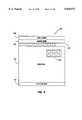
- FIG. 2is a diagram illustrating the preferred user-interface screen 140 for the OTV software tool.
- FIG. 3is a depiction of the OTV introduction window 160 which provides the user-interface for accessing the OTV software tool.
- FIG. 4is a depiction of the process map window 170 of the preferred embodiment.
- FIG. 5is a flow diagram of the process set forth in the process map window 170.
- FIG. 6is a diagram illustrating the preferred hierarchy of user-interface windows for carrying out the process of FIG. 5.
- FIG. 7is a continuation of FIG. 6 illustrating the preferred hierarchy of user-interface windows for carrying out the process of FIG. 5.
- FIG. 8is a depiction of the parse and clarify dialog window 220.
- FIG. 9is a depiction of the identifying objects dialog window 230.
- FIG. 10is a depiction of the object parsing dialog window 240 which allows the user to import a text document.
- FIG. 11is a depiction of the open file window 250 that allows the user to select the file name of the text document.
- FIG. 12is a depiction of the quick tips window 260 that informs the user of useful features and provides implementation guidance.
- FIG. 13illustrates the two-dimensional object window 270 that presents a number of objects in a two-dimensional form.
- FIG. 14illustrates the 2D object toolbar 272, and the new object tool 278 for creating new objects.
- FIG. 15illustrates the ability of objects in the 2D object window 270 to be added and moved.
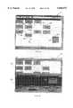
- FIG. 16illustrates the three-dimensional (3D) object window 320.
- FIG. 17is a depiction of the assigning responsibilities dialog window 330.
- FIG. 18is a depiction of the action parsing dialog window 340, which allows the user to import the text document with tagged class responsibilities.
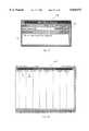
- FIG. 19illustrates the recipient list window 350, having a responsibility list, a class list, and a behavior name list.
- FIG. 20illustrates that the 3D object window 320 can be simultaneously displayed with the 2D object window 270 and the recipient list window 350.
- FIG. 21depicts a completed recipient list window 350.
- FIG. 22illustrates the creation of new classes during the responsibility design stage.
- FIG. 23illustrates a particular system model in the 2D object window 270.
- FIG. 24illustrates the relationship of the two-dimensional objects in the object window 270 to the three-dimensional cells in the 3D object window 320.
- FIG. 25illustrates that a change of location in the object window 270 simultaneously changes the locations of the cells in the 3D object window 320.
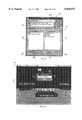
- FIG. 26is a depiction of the class editor window 290 for a selected class.
- FIG. 27is a depiction of the behaviors window 450 within the class editor window 290.
- FIG. 28is a depiction of the overview window 470 within the class editor window 290.
- FIG. 29depicts the viewpoint name window 490, and illustrates the manner in which viewpoints can be saved in the 3D objects window 320.
- FIG. 30is an overhead view in the 3D object window 320, and illustrates how saved views are denoted in the 3D object window.
- FIG. 31illustrates the toolbar icons of the 3D object toolbar 324.
- FIG. 32illustrates the capability of the OTV software tool to display the attributes of each class in the 3D object window 320.
- FIG. 33illustrates a maximized view of the flight cell 530 in the 3D object window 320 when the user elects to display attributes.
- FIG. 34displays the class editor window 290 as presented by selecting a cell in the 3D object window 290.
- FIG. 35is a depiction of the flight cell 530 having the "show attributes" function disabled, hiding the inner core of stacked attribute layers, and displaying one or more stacked opaque behavior layers.
- FIG. 36is a depiction of the interaction diagram selection window 550.
- FIG. 37is a depiction of the new interaction diagram window 560.
- FIG. 38is a depiction of the interaction diagram window 570.
- FIG. 39is a depiction of the destination class window 580, and illustrates the manner in which interactions can be created between classes in the interaction diagram window 570.
- FIG. 40illustrates how new behaviors can be added via the class editor window 290 from the interaction diagram window 570.
- FIG. 41is a depiction of the destination class window 580 including the new behavior in the behavior list field.
- FIG. 42illustrates two-dimensional interaction lines in the interaction diagram window 570.
- FIG. 43shows three-dimensional interaction lines in the 3D object window 320.
- FIG. 44illustrates a previously defined interaction diagram in the interaction diagram window 570.
- FIG. 45illustrates the preferred process of creating new interactions in a pre-existing interaction diagram.
- FIG. 46illustrates how new behaviors may be included for a class from the class editor window 290.
- FIG. 47shows the new behavior on the interaction lines of the interaction diagram window 570 and shows the three-dimensional interaction in the 3D object window 320.
- FIG. 48illustrates the manner in which new behaviors can be added from the destination class window 580.
- FIG. 49shows the destination class window 580 having the new behavior in the behavior list field 582.
- FIG. 50shows the new interaction at the seat class 624 in the interaction diagram window 570, and shows the simultaneously generated three-dimensional interaction lines in the 3D object window 320.
- FIG. 51is a depiction of the view zoom window 650.
- FIG. 52shows the interaction diagram window 570 where a custom value has been entered into the view zoom window 650.
- FIG. 53is a depiction of the preferred interaction player window 670.
- FIG. 54illustrates the interaction player window 670 when the detailed information option button is enabled.
- FIG. 55shows the playback view field 686 in the interaction player window 670.
- FIGS. 56 and 57illustrate the first person view playback when selected in the playback view field of interaction player window 670.
- FIG. 58illustrates the third person tracking view playback when selected in the playback view field of interaction player window 670.
- FIG. 59illustrates the third person non-tracking view playback when selected in the playback view field of interaction player window 670.
- FIG. 60illustrates the correlation between the interaction diagram window 570, the interaction player window 670, and a three-dimensional cell in the 3D object window 320.
- FIG. 61shows the interaction diagram window 570, the interaction player window 670, and the 3D object window 320 after playback of three interactions.
- FIG. 62illustrates an overhead view of multiple cells, and their 3D interaction lines and 3D interaction return lines.
- FIGS. 63 and 64illustrate the ability to modify interactions from the interaction diagram window 570.
- FIG. 65illustrates the ability to move object lines in the interaction diagram window 570.
- FIG. 66illustrates the ability to change the sequence of the interactions in the interaction diagram window 570.
- FIG. 67is a depiction of the interaction sequence error window 750.
- FIG. 68is a three-dimensional depiction of an interaction with the customer cell 410 in the 3D object window 320.
- FIG. 69is a depiction of the deletion warning window 772 for preventing inadvertent behavior deletions.
- FIG. 70is a depiction of the interaction deletion warning window 780.
- FIG. 71illustrates the three-dimensional customer cell 410 after the behavior layer 760 has been deleted.
- FIG. 72is a depiction of the create state diagrams window 800.
- FIG. 73is a depiction of the static relationships window 810.
- FIG. 74is a depiction of the model merge window 820.
- FIG. 75is a block diagram illustrating the development modules within the OTV application 830.
- FIG. 76is a flow diagram of a method for physically transforming an applied object-oriented programming (OOP) system or process into a visual representation.
- OOPobject-oriented programming
- FIG. 77is a flow diagram of a method for physically transforming an abstract system or process into a visual representation.
- modelingrefers to the representation of a process or system that attempts to relate a part or all of the variables in the process or system so that a better understanding of the system is attained.
- An "object”is a component or element of the model being represented, and is made of methods and data.
- the present inventionprovides a mechanism for modeling many different processes or systems, including business processes, databases, network architectures, and client-server architectures. The process or system is physically transformed into an object-oriented visual representation that allows the process or system to be viewed and manipulated in a variety of ways.
- the process or system to be modeledincludes requirements.
- a model for an airline reservation systemwould include various business requirements that define how the system should work.
- the Object Technology Visualization (OTV) software toolguides the user through the object modeling process, while capturing the necessary information to build object models. While building object models, users are able to view their model in a two-dimensional and a three-dimensional representation. Visualizing models in three dimensions provides users the opportunity to validate their models by, among other things, analyzing the emphasis placed on each object, and analyzing the associations with other objects.
- FIG. 1illustrates the Object Technology Visualization (OTV) system environment 100.
- Computer 102is shown as a stand-alone computing device, having a visual display device 104, a processing unit 106, a keyboard 108 and a pointing device 110.
- Computer 102is connected to printing device 112 to allow hardcopy documents to be printed from the OTV system.
- the OTV system environment 100may also be connected in a network configuration, where server 114 services a number of terminals for providing user interfaces for multiple users.
- Server 114can be coupled to computer 102 as seen by dashed line 116, and can be connected to other terminals 118 and 120 as shown by dashed lines 122 and 124.
- the computer 102 and terminals 118 and 120become clients of server 114 in a client-server architecture.
- the number of client terminalsis dependent on the number of users requiring access to the OTV system.
- the server 114is a data server providing the model information to the client terminals.
- the processing unit 106 in computer 102includes an internal hard disk (not shown), and further includes one or more disk drives for transferring data to and from an external diskette 126.
- server 114includes disk drive 128 for transferring data to and from diskette 126.
- Hard disk 130 in server 114is similar to the hard disk in processing unit 106, as each is capable of storing data and program information.
- the hard disk in processing unit 106, the hard disk 130, and the diskette 126all represent computer-readable mediums for storing information for use by computer 102 or server 114.
- the data representing the model informationis also stored on one or more of these computer-readable mediums.
- hard disk 130 in data server 114provides the stored model data to the client systems.
- Other computer-readable mediumscan also be used, including compact disk, read-only memory (CD-ROM) mediums.
- the OTV software toolis stored on any of the computer-readable mediums, and is executed by the computer 102 or server 114.
- the user-interface to the OTV software toolis preferably designed as a graphical user-interface (GUI).
- GUIgraphical user-interface
- pointing device 110typically a mouse or trackball
- commandsmay be issued by typing keystrokes on the keyboard 108, the user can select options by "pointing and clicking" with the mouse or trackball.
- FIG. 2is a diagram illustrating the preferred user-interface screen 140 for the OTV software tool.
- the preferred user-interfaceis a graphical user-interface (GUI) which allows a variety of different user inputs, including menu-driven input, toolbar input, and keystroke input. Keystroke input is accomplished by activating predefined key assignments on keyboard 108, which carries out the predefined function.
- GUIgraphical user-interface
- the user-interface of FIG. 2includes menu bar 142 which allows menu-driven input by selecting menu items within a pull-down menu box.
- Toolbars 144 and 146which can typically be moved to different locations within the user-input screen 140, allow the user to execute commands and functions by selecting command icons within the toolbars 144 and 146.
- the user-input screen 140also includes a title bar 148 which identifies the OTV software tool.
- Status bar 150provides status and instructions for the OTV software tool.
- Window area 152is the area in which the various user-interface windows of the OTV software tool are displayed.
- FIG. 3a depiction of the OTV introduction window 160, which provides the user-interface for entering the OTV system, is shown.
- Introduction window 160provides quick entry to predetermined areas of the system. Clicking on the quick preview box 162 takes the user through a guided tour of the features of the OTV software tool. Clicking on the open file box 164 allows the user to open the OTV user file most recently used. Clicking on the new file box 166 allows the user to create a new OTV user file.
- FIG. 4is a depiction of the process map window 170 of the preferred embodiment.
- a new filemay be opened by selecting the new file box 166 of FIG. 3, or by way of the other available user-inputs including the previously described menu-driven input, toolbar input, and keystroke input.
- the process map window 170is presented, which guides the user through the object-oriented design process. Selection of a process icon in process map window 170 automatically takes the user to a different step in the object modeling process.
- the process icons in process map window 170include the parse & clarify process icon 172, the object process icon 174, the responsibilities process icon 176, the descriptions process icon 178, the collaborations process icon 180, the diagram states process icon 182, the encapsulation process icon 184, and the static relationships process icon 186.
- FIG. 5is a flow diagram of the process map window 170 of FIG. 4.
- the processbegins at start step 190, where the process map window 170 is presented.
- Step 192includes creating a process document where the process requirements are parsed and clarified.
- Step 192is initiated by selecting the parse & clarify process icon 172.
- Selection of the object process icon 174advances processing to step 194, where classes of the model are identified, and model objects are created.
- processingcontinues at step 196, which is initiated by selection of the responsibilities process icon 176.
- Step 196involves identifying and assigning responsibilities to the classes identified in step 194.
- the ability to continually enhance and modify the modelis apparent at step 198, where the classes are further defined by further clarifying the responsibilities. This includes clarifying attributes, behaviors and collaborations for the classes.
- Step 198is initiated by selecting the descriptions process icon 178 in the process map window 170.
- Step 200involves the creation of interaction diagrams that allow the collaborations between the objects to be evaluated. Specific interactions between objects can be created, modified or deleted at step 200.
- Steps 202, 204 and 206allow the user to view various aspects of the model that was created.
- Step 202is initiated by selecting the diagram states process icon 182, which allows the user to view the dynamic aspect of a class.
- the usercan view the role that each object plays in the model at step 204 by selecting the encapsulation process icon 184.
- the static relationships of the modelcan be viewed at step 206 by selecting the static relationships process icon 186. Processing continues at decision step 208, where it is determined whether the model is complete.
- step 210If the user has completed the model, the process ends at stop step 210. If the process is to be further enhanced, the model is not complete, and processing is returned to step 198, where the classes, attributes, behaviors and collaborations can be further defined. It should be noted that any of the process icons in the process map window 170 can be selected to return to any particular step in the flow diagram of FIG. 5 if the user so desires.
- FIG. 6a diagram illustrating the preferred hierarchy of the user-interface windows for carrying out the process of FIG. 5 is shown. From process map window 170, user-interface windows can be initiated for each of the steps 192 through 206 by selecting the corresponding process icon. Each of the windows will be described in detail throughout this description, however FIG. 6 provides a map of the window relationships.
- Selection of the parse and clarify process icon 172presents the parse and clarify dialog window 220.
- Selection of the object process icon 174provides the user with the identifying objects dialog window 230, which in turn provides the object parsing dialog window 240. Where a file is to be opened, the open file window 250 is opened to allow the user to select a file. Finally, quick tips window 260 is provided upon selection of a file.
- Selection of object process icon 174also provides the user with access to a two-dimensional object window and a three-dimensional object window, which are described in FIG. 7.
- Continuation indicators 6-1 and 6-2depict the connection points of FIG. 6 to the corresponding continuation indicators of FIG. 7.
- Selection of the responsibilities process icon 176also provides the user with access to the two-dimensional object window and the three-dimensional object window described in FIG. 7.
- Continuation indicators 6-1 and 6-2again depict the connection points of FIG. 6 to the corresponding continuation indicators of FIG. 7.
- Two other windowsare available by selecting the responsibilities process icon 176, including the assigning responsibilities dialog window 330 and the recipient list window 350. From the assigning responsibilities dialog window 330, the user can also access the action parsing dialog window 340.
- Selection of the descriptions process icon 178allows the user to modify and refine the system model. This is accomplished through the two-dimensional and three-dimensional object windows described in FIG. 7. Again, continuation indicators 6-1 and 6-2 depict the connection points of FIG. 6 to the corresponding continuation indicators of FIG. 7.
- the collaborations process icon 180when selected, presents the interactions diagram selection window 550.
- the usercan create a new interaction diagram from the new interactions diagram window 560, or view and modify an existing interaction diagram.
- the interaction diagram window 570is provided.
- the usercan access the destination class window 580, the view zoom window 650, and the interaction player window 670.
- the class editor window 290can be accessed, which provides the attributes window 428, the behaviors window 450, and the overview window 470.
- the three-dimensional viewcan also be accessed, which is described in FIG. 7 and connected to the flowchart of FIG. 7 via the continuation indicator 6-1.
- Selection of the diagram states process icon 182presents the user with the create state diagrams window 800.
- Selection of the encapsulation process icon 184again is accomplished through the two-dimensional and three-dimensional object windows described in FIG. 7.
- Continuation indicators 6-1 and 6-2depict the connection points of FIG. 6 to the corresponding continuation indicator of FIG. 7. Because system modeling is an iterative process, the encapsulation step allows the user to view the role of each object in the system model, and further enhance the system model by modifying the classes, attributes, and behaviors.
- selection of the static relationships process icon 186presents the static relationships window 810.
- FIGS. 6 and 7provide a guide to some of the major user-interface windows of the OTV software tool, however other user-interface windows also exist within the OTV software tool.
- Continuation indicators 6-1 and 6-2are extensions of the flowchart of FIG. 6. From continuation indicator 6-1 is the preferred hierarchy of the three-dimensional user-interface windows.
- the 3D object window 320is the main three-dimensional window that provides a three-dimensional view of the system model. From the 3D object window 320, the user can access the class editor window 290, which in turn provides the attributes window 428, the behaviors window 450, and the overview window 470. The user can also access the 3D object toolbar 324 and the viewpoint name window 490 from the 3D object window 320.
- the object window 270is the main two-dimensional window that provides a two-dimensional view of the system model. From the object window 270, the user can access the class editor window 290, which in turn provides the attributes window 428, the behaviors window 450, and the overview window 470. The 2D object toolbar 272 and the view zoom window 650 can also be accessed from the object window 270.
- This first step of parsing and clarifying system requirementsallows the user to identify and set forth the requirements of the process or system. These requirements can be entered using a word processing application which can be launched by selecting button 222 in the parse and clarify dialog window 220.
- the word processing application usedis Microsoft® Word
- selection of button 222will initiate the Microsoft® Word word processing program.
- Other word processing programscould be used without departing from the scope of the invention.
- the userenters the system requirements into a word processing document which will define the system requirements for the current system model. Alternatively, such a document may be a pre-existing document previously prepared setting forth the system requirements. The user may use the pre-existing document to define the system requirements for the current system model. Table 1 shows an example of possible system requirements for an airline reservation business model.
- the done button 224 in the parse and clarify dialog window 220is selected to return the user to the process map window 170.
- the parse & clarify process icon 172 in FIG. 4is then marked, letting the user know that this step has been carried out. The user may, however, return to the parse and clarify step 192 of FIG. 5 by selecting the parse & clarify process icon 172 at any time.
- Selecting the object process icon 174 of FIG. 4allows the user to identify potential objects after the system requirements have been clarified.
- the result of identifying potential objectswill be a group of classes for the model.
- the identifying objects dialog window 230 of FIG. 9is provided.
- the document of Table 1is then loaded into the word processing application to identify the potential objects. This is accomplished by selecting button 232 of the identifying objects dialog window 230, which again activates the word processing application.
- Object words in the system requirements document of Table 1can be tagged to identify the various classes of the system model. In the preferred embodiment, these objects are tagged by boldfacing potential objects in the system requirements document.
- Table 2shows the system requirements of the word processing document after having been tagged by boldfacing the potential system objects.
- the done button 234 in the identifying objects dialog window 230 of FIG. 9is then selected to return the user to the process map window 170.
- the object parsing dialog window 240is presented to the user upon clicking the done button 234 as shown in FIG. 10.
- the object parsing dialog window 240allows the user to import the document of Table 2 which has its potential business objects tagged as boldfaced words. If no document is to be imported, the user selects the no button 242 to close the object parsing dialog window 240.
- the open file window 250 of FIG. 11is provided to allow the user to select the file name of the word processing document created from the text of Table 2.
- the desired file nameis selected by selecting the name of the file in the file list field 252 after selecting the appropriate directory from the directory list field 254, and selecting the OK button 256.
- FIG. 12is a depiction of the quick tips window 260.
- the quick tips window 260is provided to the user the first time the object process icon 174 is selected and the user has opened a document from the file open window 250 or has chosen not to import a document by selecting the no button 242 in the object parsing dialog window 240.
- the quick tips window 260informs the user of useful features used in identifying objects, and provides guidance on how to implement the corresponding menu, toolbar or keystroke command.
- FIG. 13shows object window 270 which depicts a number of objects in a two-dimensional form.
- Each of the objects which were tagged in the document of Table 2are separately presented as a two-dimensional object in 2D object window 270.
- Four object toolsare shown in the 2D object toolbar 272.
- the pointer object tool 274allows the two-dimensional objects in 2D object window 270 to be moved from their current locations to new locations in the 2D object window 270.
- the text object tool 276, when selected,allows the user to enter text into 2D object window 270.
- the new object tool 278, when selected,allows the user to add new objects in addition to the current objects in 2D object window 270.
- the link object tool 280when selected, allows the user to draw lines connecting certain objects to show a relationship between those connected objects.
- Class name entry field 292allows the user to enter the name of the new class, which is shown as "ticket" in FIG. 14. A description of this class can be entered in the class description field 294. A new object will be entered in the 2D object window 270 upon selecting the OK button 296 in the class editor window 290.
- FIG. 15illustrates the ability of objects in 2D object window 270 to be added and moved.
- the ticket object 300 created by the class editor window 290 of FIG. 14is shown in 2D object window 270.
- Objectshave been moved by selecting the pointer object tool 274 in the 2D object toolbar 272, selecting the desired object with the cursor arrow 302, and moving the selected object to a new location.
- Some of the objects in 2D object window 270are also shown to be linked. This is accomplished by selecting the link object tool 280, and selecting two objects to be linked.
- the carrier object 304 of FIG. 15is linked to the seats object 306, which is in turn linked to the waiting list object 308.
- the reservation object 310is shown linked to the customer object 312.
- the flight object 314is linked to the customer object 312, the waiting list object 308, and the schedule object 316.
- Linkingis performed when the link object tool 280 is selected, a first object is selected by clicking on the object in the 2D object window 270, and clicking on a second object to be linked. This linkage shows that there is some relationship between the linked objects.
- the OTV software toolprovides various graphics options to change or enhance the 2D object window 270. These graphics options can be selected by way of the different user inputs, including menu-driven input, toolbar input, and keystroke input.
- the various optionsinclude fill patterns, pen styles, colors, alignment and fonts. Using these and other options allow the visual depiction in the 2D object window 270 to be set or changed at the user's preference.
- the OTV software toolalso includes various viewing options, which also can be selected by way of the different user inputs, including menu-driven input, toolbar input, and keystroke input.
- the viewing optionsinclude toggle switches for viewing the status bar 150 shown in FIG. 2, the 2D object toolbar 272, and a visual grid.
- a "snap-to-grid" toggle functionis also provided to ease alignment and movement of the objects.
- a three-dimensional viewing windowis provided by the OTV software tool. Viewing the object model in three dimensions allows users to view their model quantitatively, and interactions between the objects are brought to life. A three-dimensional view of the 2D object window 270 can be initiated by way of any of the different user inputs.
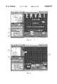
- the 3D object window 320is shown.
- the 3D object window 320is shown concurrently with the 2D object window 270 to form a split image in a single object window 322.
- the 3D object window 320provides a three-dimensional view of 2D object window 270, as the same objects and their relative positions in the 2D object window 270 are shown in three dimensions in the 3D object window 320.
- a 3D object toolbar 324 in object window 322allows the user to move through the 3D object window 320, in order to view the objects from various vantage points.
- a classis defined by its collective responsibilities, including its attributes and behaviors. By describing the responsibilities of each class, the role that each class plays is defined within the system model.
- step 196 of identifying and assigning responsibilities to the classesis initiated by selecting the responsibilities process icon 176.
- Selection of the responsibilities process icon 176opens the assigning responsibilities dialog window 330 as shown in FIG. 17.
- the assigning responsibilities dialog window 330allows the user to tag the actions that each of the classes are responsible for providing.
- the word processorcan again be initiated by clicking on button 332 in the assigning responsibilities dialog window 330.
- the system requirements in the documentare again tagged, this time tagging the actions of each class.
- the tagging of the actions of each classis accomplished by italicizing action phrases associated with each of the objects.
- action phrasescould alternatively be tagged in other ways without departing from the scope of the invention, such as underlining, capitalization, etc.
- the tagging of action phrasescan be seen in Table 3, where the actions have been tagged by italicizing various phrases.
- the italicized wordsare also underlined for illustrative purposes in Table 3 to allow the tagged phrases to be seen more clearly in the table.
- the done button 334 in the assigning responsibilities dialog window 330is selected, indicating that the tagging is complete, and closing the assigning responsibilities dialog window 330.
- FIG. 18shows the action parsing dialog window 340, presented upon selecting the done button 334 of the assigning responsibilities dialog window 330, which allows the user to import the document with the tagged class responsibilities shown in Table 3.
- the userhas the option of not importing the document by selecting the no button 342, whereby the user would manually enter the class responsibilities. Otherwise, the user selects the yes button 344 in the action parsing dialog window 340 to import the document having the tagged class responsibilities.
- the OTV software toolrecognizes the tagged, italicized action phrases, and automatically enters those phrases into a responsibility list of the recipient list window 350 of FIG. 19.
- FIG. 19shows the recipient list window 350, having a responsibility list 352, a class list 354 and a behavior name list 356.
- the individual tagged action phrasesare automatically entered into the responsibility list 352.
- the responsibilities listed in the responsibility list 352are each assigned to a class, which is entered into the class list 354.
- Each of the responsibilities listed in the responsibility list 352are also assigned a behavior name in the behavior name list 356, which provides a name for the corresponding responsibility.
- the 2D object window 270can be shown simultaneously with the recipient list window 350 to assist the user in defining the classes and behaviors.
- FIG. 20further illustrates that the 3D object window 320 can also be simultaneously displayed with the 2D object window 270, and the recipient list window 350.
- the three-dimensional viewprovides immediate feedback to the user when assigning behavior names to classes, as will be shown in more detail below.
- Each of the tagged responsibilities in the responsibility list 352is assigned to a particular class, where each class represents one of the objects in 2D object window 270 and 3D object window 320.
- FIG. 20illustrates how classes are assigned to each of the responsibilities in the responsibility list 352.
- a classcan be directly entered into each field of class list 354, or can be selected from a pull-down list 358 of classes displayed by clicking on the pull-down button 360, and clicking on the desired class in the pull-down list 358.
- Each of the responsibilities in the responsibility list 352can similarly be assigned to a class.
- the recipient list window 350is shown having a completed responsibility list 352, class list 354, and behavior name list 356.
- Each of the responsibilities in the responsibility list 352has been assigned to a class in the class list 354.
- Behavior names associated with the responsibilities in the responsibility list 352are shown in the behavior name list 356.
- Each of the behavior names in the behavior name list 356is a user-generated name that the user creates to identify one of the responsibilities in the responsibility list 352.
- Behaviorsdescribe the capabilities that a particular class can provide.
- a behavioris a method associated with a class that defines the responsibility of that class. For instance, in the responsibility field 362, the responsibility is to "find a flight that meets the requested schedule". The item being acted on is the schedule, which represents the class, and the behavior associated with that responsibility for that class is named "FindFlight" in behavior field 364.
- the behaviorsare dynamically added to the classes in the 3D object window 320. For example, the class labeled "waiting list" in class list 354 has three behaviors associated with it in behavior fields 366, 368, and 370.
- IsWaitingListIsFreqWaitingList
- IsRegWaitingListbehaviors are dynamically added to the three-dimensional view of the waiting list class in the 3D object window 320.
- the classesare shown in the 3D object window 320 as three-dimensional "cells", which are the three-dimensional representations of the two-dimensional "objects" in the 2D object window 270.
- the waiting list cell 372shows the corresponding behaviors in behavior blocks 374, 376 and 378.
- the waiting list cell 372can be dynamically brought into the view shown in FIG. 21 by clicking on the waiting list cell 372 from any view within the 3D object window 320.
- FIG. 22illustrates how new classes can be added during the responsibility design stage.
- the class editor window 290By selecting the new object tool 278 in the 2D toolbar 272 in 2D object window 270, the class editor window 290, previously shown in FIG. 14, is opened. The name of the new class is then entered into the class name entry field 292, and a description of the new class is entered into the class description field 294.
- the new class object 380is shown in the 2D object window 270, and is also shown as a new class cell 382 in the 3D object window 320.
- Selection of the pointer object tool 274 in the 2D toolbar 272allows the new class object 380 to be moved within the 2D object window 270, which will simultaneously move the three dimensional new class cell 382 in the 3D object window 320.
- moving the cells in the 3D object window 320automatically moves the objects represented in the 2D object window 270.
- step 198 of FIG. 5is initiated by selecting the descriptions process icon 178 of FIG. 4.
- Step 198allows the user to describe the classes and their behaviors to clearly define the rule of each class in the model and to define the services that it provides.
- the desired system modelcan be captured in the 2D object window 270 of FIG. 23.
- the system model in FIG. 23has seven objects, including the customer object 390, the reservation object 392, the segment object 394, the carrier object 396, the flight object 398, the seat object 400, and the waiting list object 402. When these objects have been defined after performing steps 192, 194 and 196 in the flow chart of FIG. 5, the user can further define and describe the classes and their behaviors.
- the objects in the 2D object window 270are also shown as three dimensional cells in the 3D object window 320.
- the pointer object tool 274 in the 2D object toolbar 272(shown in FIG. 13) allows objects to be moved within the 2D object window 270.
- the cells in the 3D object window 320can also be moved within the 3D object window 320 by selecting and moving the desired cell, which can be accomplished by clicking on the desired cell and "dragging" it to a new location.
- FIG. 24also illustrates the relationship between the locations of the two-dimensional objects in the 2D object window 270 and the locations of the three-dimensional cells in the 3D object window 320.
- the customer object 390is shown located to the left of the reservation object 392 in the 2D object window 270.
- the segment object 394is positioned directly in front of the reservation object 392.
- the 3D object window 320it can be seen that the three-dimensional customer cell 410 is located to the left of the reservation cell 412, and the segment cell 414 is positioned directly in front of the reservation cell 412. Therefore, the relative positions of the objects in the 2D object window 270 parallel the relative positions of the cells in the 3D object window 320.
- a change of location in the 2D object window 270simultaneously changes the locations of the cells in the 3D object window 320.
- the reservation object 392has been moved to the left, to the original position of the customer object 390.
- the customer object 390has been moved to the right, to a point beyond the original position of the reservation object 392.
- the segment object 394has been moved to the left so that it is located in front of, and approximately between, the reservation object 392 and the customer object 390.
- the customer cell 410, the reservation cell 412, and the segment cell 414 in the 3D object window 320have also been automatically repositioned according to the new locations in the 2D object window 270.
- the reverseis also true, that is, repositioning of the cells in the 3D object window 320 automatically repositions the objects in the 2D object window 270.
- the attributes and behaviors associated with each classcan be modified within the 2D object window 270 or the 3D object window 320.
- the attributes and behaviors associated with a particular classcan be modified by double-clicking on the desired object when the pointer object tool 274 is selected.
- the attributes and behaviors associated with a particular classcan be modified by double-clicking on the desired cell. Selecting the desired object or cell in the above manner presents the class editor window 290 for the selected class, where modifications to the class can be performed.
- FIG. 26shows the class editor window 290 for a selected class. Where an object or cell is selected from the 2D object window 270 or the 3D object window 320, the class editor window 290 is presented having all associated information for that class which was entered into the recipient list window 350. For example, FIG. 26 displays the class editor window 290 where the reservation cell 412 was selected from the 3D object window 320.
- the class editor window 290is the same class editor window 290 of FIG. 14, except that an option within the class editor window 290 has been selected.
- the class editor display button 420 in the class editor window 290allows the user to toggle between displaying an abbreviated version of the class editor window 290 as shown in FIG. 14, and the full version as shown in FIG. 26.
- Selecting the class editor display button 420 when the full version of the class editor window 290 is displayedreduces the class editor window 290 to its abbreviated version shown in FIG. 14.
- the abbreviated versionis accomplished by hiding the lower portion of the class editor window 290 that includes the overview tab 422, the attributes tab 424, and the behaviors tab 426. Selecting the class editor display button 420 again would restore the full display as shown in FIG. 26.
- the class editor window 290 of FIG. 26includes the class name entry field 292, which automatically presents the name of the class associated with the object or cell selected from the 2D object window 270 or the 3D object window 320 respectively.
- the selected class for this caseis the "reservation" class.
- the class description field 294includes a description of the reservation class.
- the usercan select any one of the overview tab 422, the attributes tab 424 and the behaviors tab 426.
- the attributes window 428is shown, which is presented upon selection of the attributes tab 424.
- Selection of the attributes tab 424presents an attribute name field 430, and an attribute descriptions field 432 in the attributes window 428.
- the attribute name field 430allows the user to enter a new attribute for the reservation class, or view an existing attribute.
- a description of the attributeis presented in the attribute description field 432.
- a new attributehas been added to the reservation class.
- the attributehas been named "date" in the attribute name field 430, and is described in the attribute description field 432 as "This holds the date requested".
- the new button 434 in attribute window 428is selected.
- the usercan also decide not to enter the new attribute by selecting the cancel button 436.
- Existing attributes and their descriptionscan be viewed by selecting the attribute pull-down button 438, which provides a selectable list of the current attributes associated with the class.
- the class editor windowis closed with changes saved by selecting the OK button 296, and is closed without saving changes by selecting the cancel button 420.
- FIG. 27shows the behaviors window 450 which is presented upon selection of the behaviors tab 426 from the class editor window 290.
- a new behaviorcan be entered in the behavior name field 452, or an existing behavior can be entered in the behavior name field 452 by selecting the behavior pull-down button 454 and selecting an existing behavior from a list of existing behaviors.
- an existing behavior labeled "AcceptSegment"has been selected in the behavior name field 452.
- a description of the behavior in the behavior name field 452is provided in the behavior description field 456.
- the returns field 458allows the user to describe the return value of the behavior named in the behavior name field 452.
- the collaborators field 460is automatically filled out for the behavior named in the behavior name field 452 based on information provided during the collaboration step.
- Each of the entries in the collaborators field 460represents an interaction from the class named in the class name entry field 292 to the class named in the particular entry in the collaborators field 460.
- the behaviors associated with of the classes in the collaborators field 460are also listed. For example, an entry in the collaborations field 460 which reads "Carrier::ProvideFlightList” represents an interaction from the reservation class named in the class name entry field 292 to the carrier class. The behavior associated with this interaction is the "ProvideFlightList" behavior.
- the returns field 458 and the collaborators field 460will be described in more detail in connection with the description of the interaction diagrams described below.
- New behaviors and their descriptionsare entered by the user into the behavior window 450.
- a new behavior nameis entered into the behavior name field 452, and a description and a return value are then entered into the behavior description field 456 and the returns field 458 respectively.
- the new behavioris accepted upon selection of the new button 462.
- Any of the existing behaviors, which are presented upon selection of the behavior pull-down button 454,can be deleted from the system by selecting the delete button 464 in the behaviors window 450.
- the overview window 470 of the class editor window 290is shown. Selection of the overview tab 422 presents an attribute list 472 and a behaviors list 474. All of the attributes associated with the class in the class name entry field 292 are listed in the attribute list 472. Similarly, all of the behaviors associated with the class in the class name entry field 292 are listed in the behaviors list 474.
- the overview tab 422can be selected from the class editor window 290 at any time to view a particular class's attributes and behaviors.
- the overview window 470When the user has entered a new attribute, the overview window 470 will update the attribute list 472 to include the new attribute.
- the attribute list 472shows the new attribute named "date". New attributes can also be entered from the overview window 470 by selecting the new attribute button 476 from the overview window 470. The user can similarly delete an attribute from the attribute list 472 by selecting the desired attribute in the attribute list 472, and then selecting the delete attribute button 478 located under the attribute list 472.
- the overview window 470will update the behavior list 474 to include the new behavior.
- the behavior list 474 in FIG. 28shows the behaviors currently associated with the reservation class. New behaviors can be entered by selecting the behaviors tab 426 as previously described, or they can also be entered from the overview window 470 by selecting the new behavior button 480 from the overview window 470.
- the usercan delete a behavior from the behavior list 474 by selecting the desired behavior in the behavior list 474, and then selecting the delete behavior button 482 located under the behavior list 474.
- FIG. 29illustrates the manner in which viewpoints can be saved in the 3D objects window 320.
- the "add viewpoint" functioncan be initiated by various user input mechanisms, including menu-driven input.
- One of the menu selections on the menu bar 142is a view menu selection, which includes sub-menus.
- One sub-menu itemallows the user to save a particular view in the 3D object window 320 for future reference.
- the usercan move to any view within the 3D object window 320, and open the viewpoint name window 490 by selecting the corresponding sub-menu or by providing other appropriate user input.
- the viewpoint name window 490allows the user to enter a name for the view being saved.
- the name entered in the viewpoint name field 492is "In Front of SEGMENT", which is saved as the viewpoint name when the user selects the OK button 494. Saving a viewpoint name can be canceled, if desired, by selecting the cancel button 496.
- a saved viewpoint nameis made available to the user by entering appropriate user input.
- the saved viewpoint nameis added to a list of viewpoint names in a menu list. The desired view can then be seen by choosing the desired viewpoint name from the menu list. This will automatically change the view in the 3D objects window 320 to the view that was captured at the time the viewpoint name was saved. Viewpoint names can also be deleted from the list when the saved view is no longer needed.
- two default viewsare always available to the user, which are named the "overhead view” and the "ground view”.
- Selection of the ground view viewpoint name from the viewpoint name menu listautomatically changes the view in the 3D object window 320 to a view as seen from the plane on which the cells in the 3D object window 320 are positioned.
- Selection of the overhead view viewpoint name from the menu list of viewpoint namesprovides a view in the 3D object window 320 which is perpendicular to the plane on which the cells are positioned, or in other words, from the top of the cells.
- FIG. 30illustrates an overhead view in the 3D object window 320, and further illustrates how saved views can be denoted in the 3D object window 320.
- the overhead viewdisplays the class objects as seen from a vantage point above and approximately perpendicular to the plane on which the cells are positioned.
- the vantage point from which a particular view was savedcan be denoted in the 3D object window 320 by selecting a "show viewpoint" function that can be initiated by various user input mechanisms, including menu-driven input.
- the view menu selection on the menu bar 142 in the preferred embodimentincludes a menu selection item that toggles viewpoint indicators on and off. When enabled, viewpoints indicators are shown in the 3D object window 320, as is seen by viewpoint indicator 500 in FIG. 30.
- the viewpoint indicator 500represents the vantage point from which the "In Front of SEGMENT" view was saved using the viewpoint name window 490 shown in FIG. 29. Referring to FIGS. 29 and 30, it can be seen that the viewpoint indicator 500 is located in a position from which the view was saved in the 3D object window 320 in FIG. 29.
- the viewpoint indicator 500 of the preferred embodimentis represented as a cone-shaped icon which points in the direction of the saved view from the location of the saved view.
- viewpoint indicatorscan be seen in any view within the 3D object window 320, whether from the ground view, the overhead view, or any other view created by the user.
- the viewpoint indicatorscan also be seen as the user moves throughout the 3D object window 320 using the 3D object toolbar 324.
- the userselects directional icons from the 3D object toolbar 324, as shown in FIG. 31.
- These directional iconsallow the user to maneuver around the cells in the 3D object window 320 to view the three-dimensional model from any vantage point.
- the left arrow icon 510dynamically changes the view as if rotating a line of sight to the left.
- the forward arrow icon 512dynamically changes the view in the 3D object window 320 as if moving forward into the three-dimensional view.
- the right arrow icon 514dynamically changes the view as if a line of sight was rotated to the right.
- the reverse arrow icon 516changes the view to back away from the current view in the 3D object window 320.
- the rotate icon 518changes the view as if the viewer were rotating around a substantially central point in the 3D object window 320.
- the up arrow icon 520changes the view by raising the viewing vantage point to a higher location.
- the down arrow icon 522changes the view by lowering the viewing vantage point, which can be lowered until the ground plane is reached.
- the cycle viewpoint icon 524allows the user to toggle between views that have been saved using the viewpoint name window 490, as well as the default views which in the preferred embodiment include the ground view and the overhead view. Each time the cycle viewpoint icon 524 is selected, the next viewpoint is activated, and the user is taken to that view in the 3D object window 320.
- the "show attributes" functioncan be initiated by various user input mechanisms, including menu-driven input.
- the userselects a menu selection item that toggles the display of attributes on and off.
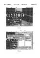
- the view shown in FIG. 32displays the 3D object window 320 when the show attributes function has been toggled to the "on" position, thereby displaying the encapsulated attribute data within each cell.
- the outer shell of each cellbecomes partially transparent, leaving each outer shell displayed as a wire frame 534.
- the attributes associated with each cellbecome visible, being displayed as an inner core of one or more stacked attribute layers surrounded by the wire frame 534 outer shell.
- FIG. 33illustrates a maximized view of the flight cell 530 in the 3D object window 320 when the user elects to display attributes.
- the outer shell, or the surface walls of the flight cell 530are transparent, and an attribute box 532 representing the stacked attribute layers within the flight cell 530 becomes visible.
- Thisallows the user to view, modify, or add attributes for the class represented by the cell, by opening of the class editor window 290 as seen in FIG. 34.
- the class editor window 290automatically presents the name of the class associated with the selected attribute in the class name entry field 292.
- the attributes associated with the respective classare then presented in the attribute list 472 of the overview window 470. At this point, attributes and behaviors can be added or deleted as described in connection with FIGS. 26, 27 and 28.
- the flight cell 530is shown having the show attributes function disabled.
- the outer shell of the flight cell 530becomes visible, hiding the inner core of stacked attribute layers, and displaying one or more stacked opaque behavior layers 536.
- the three-dimensional flight cell 530lists its associated behaviors on its outer shell.
- a "show behavior names" functioncan be initiated by various user input mechanisms, including menu-driven input. In the preferred embodiment, the user selects a menu selection item that toggles the display of behavior names on behavior layers 536 on and off.
- the outer shelldisplays the one or more stacked opaque behavior layers relating to the behaviors of the class corresponding to the cell. In FIG.
- the stacked opaque behavior layers 536display the behavior names "AddToWaitingList”, “CheckStatus”, “AvailableSeats”, and "MatchConditions", which parallel the behavior names in the behavior list 474 of the class editor window 290 of FIG. 34.
- Each of these layersis labeled with the respective behavior name when the show behavior names function is enabled.
- the show behavior names functionis disabled, the stacked opaque behavior layers are still visible, but the behavior name labels are not visible thereon.
- a "collaboration”is a relationship that exits between two or more objects to fulfill the responsibility of a certain object.
- the process of finding collaborations between objectshelps to identify the communication and relationships between objects. This is an important step in determining the points of intersection between classes, and helps to minimize the number of interactions between objects.
- An interaction diagramis one way to display the collaborations which occur in a given scenario.
- Collaborationsare entered at step 200 of FIG. 5 by selecting the collaborations icon 180 in FIG. 4. Selection of the collaboration icon 180 presents the interaction diagram selection window 550 as shown in FIG. 36. A list of existing interaction diagrams will be shown in the interaction list field 552 to allow the user to select collaborations previously entered by selecting the interaction, and selecting the OK button 554. New interactions can be entered by selecting the new button 556. Selecting the new button 556 opens the new interaction diagram window 560 as shown in FIG. 37. The new interaction diagram window 560 allows the user to enter a name for the interaction diagram in the interaction diagram name field 562, and a description of the new interaction diagram in the interaction diagram description field 564. Selection of the OK button 566 on the new interaction diagram window 560 opens the interaction diagram window 570 as shown in FIG. 38.
- the interaction diagram window 570 of FIG. 38allows the user to map interactions between objects to help identify the communication relationships. Collaborations between classes are created by drawing a line from one class to another class.
- the class labeled interface 572is a starting point for the interaction diagram. Using a pointing device such as a mouse, a line 574 can be drawn from the interface object line 578 to the carrier object line 579 as shown in FIG. 39. Upon releasing the mouse button near the carrier object line 579 associated with the carrier class 576, the destination class window 580 for the carrier class is presented.
- the behaviors associated with the carrier classare listed in the behavior list field 582. Any of the behaviors in the behavior list field 582 can be selected as the behavior interaction between the interface class 572 and the carrier class 576.
- New behaviorscan be added in the behavior list field 582 by selecting the class editor button 584 which opens the class editor window 290 as shown in FIG. 40.
- the new behaviorcan be entered in the behavior name field 452 in the behavior window 450, and a description of that new behavior can be added in the behavior description field 456.
- the new behavioris accepted upon selection of the OK button 296.
- the destination class window 580is shown to include the new behavior in the behavior list field 582.
- the new behavioris then selected by highlighting the new behavior, and selecting the OK button 586.
- a directional interaction line 588 labeled NewBehavioris then created from the interface object line 578 to the carrier object line 579 as shown in FIG. 42.
- a return interaction line 590is unlabeled because the returns field 458 in the class editor window 290 of FIG. 40 was left blank. This interaction diagram therefore includes an action called NewBehavior, and processing then returns to the interface class 572 with no return value. Additional interactions between other classes are created similarly.
- the NewBehavior interaction line 588 of FIG. 42is shown as three-dimensional NewBehavior interaction line 600, shown entering the carrier cell 602 proximate the behavior labeled NEWBEHAVIOR on the outer shell of the carrier cell 602.
- the 3D return interaction line 604corresponds to the return interaction line 590 in the interaction diagram window 570 of FIG. 42, and is shown exiting the carrier cell 602 proximate the behavior labeled NEWBEHAVIOR on the outer shell of the carrier cell 602.
- FIG. 44illustrates a previously defined interaction diagram in the interaction diagram window 570.
- This interaction diagramcan be loaded in the interaction diagram window 570 by selecting the interaction diagram labeled "Book Flight" in the interaction diagram selection window 550 of FIG. 36. All interaction lines and interaction return lines can be seen in the interaction diagram window 570.
- the order in which the classes are presented in the interaction diagram window 570can be modified in the interaction diagram window 570.
- a classcan be moved to change the appearance of the interaction lines in the interaction diagram window 570.
- the carrier class 574is shown to the immediate right of the interface class 572.
- the text "Carrier”can be moved to the location shown in FIG. 44.
- the carrier class 574is shown as the fourth class to the right of the interface class 572.
- the carrier class 574, along with all of its associated interactions,are redrawn at the new location.
- FIG. 45the process of creating new interactions in a pre-existing interaction diagram is shown.
- the userclicks on the flight object line 610 and drags the mouse pointer to the seat object line 612.
- Releasing the mouse button proximate the seat object line 612presents the destination class window 580 which lists all the behaviors associated with the seat class in the behavior list field 582. Any of the behaviors in the behavior list field 582 can be selected by highlighting the desired behavior and clicking on the OK button 586.
- the usermay select the class editor button 584, which allows the user to add new behaviors for particular classes from the class editor window 290 as shown in FIG. 46.
- the class editor button 584 in the destination class window 580 of FIG. 45can also be selected to review or amend the behavior name, the description and return value in the class editor window 290.
- the class editor window 290shows the behavior name in the behavior name field 452, the description of the behavior in the behavior description field 456, and the return value in the returns field 458, from which the behavior name, the description and the return value can be modified.
- the behavior labeled "MatchCondition" on interaction line 620 from the behavior name field 452 of FIG. 46is shown extending from the flight object line 610 to the seat object line 612.
- the return value in the returns field 458 of FIG. 46can be seen on the return interaction line 622, which shows the return value labeled "True if conditions match" from the seat object line 612 to the flight object line 610.
- This return valueis derived from the return value entered in the returns field 458 of the class editor window 290 of FIG. 46.
- the interaction line 620 and the return interaction line 622 in the interaction diagram window 570are also shown as 3D interaction line 628 and 3D interaction line 630 between the flight cell 530 and the seat cell 632 in the 3D object window 320, which is shown from the overhead view.
- FIG. 48illustrates the manner in which new behaviors can be added from the destination class window 580 of FIG. 45.
- the class editor button 584is again selected.
- the systempresents the class editor window 290 having the name of the class in the class name entry field 292.
- a new behaviorcan be entered as previously described by selecting the behaviors tab 426, which opens the behaviors window 450.
- the new behavior nameis then entered into the behavior name field 452, which for the present example is labeled "IsWindowSeat".
- a description of the new behavioris entered into the behavior description field 456, and the return value is entered into the returns field 458.
- the OK button 296the class editor window 290 is closed, and the destination class window 580 displays the new behavior labeled IsWindowSeat in the behavior list field 582.
- the usermay decide to add a new behavior upon analyzing the interactions in the interaction diagram window 570.
- the usermay determine that an interaction within a single class is necessary. For instance, the user may select the seat object line 612 by clicking and releasing on the seat object line 612. This will present the destination class window 580, and the class editor window 290 can be activated as discussed above.
- the new behavior named "IsWindowSeat" in the behavior name field 452is the new behavior for the interaction from the seat class 624 to itself.
- the destination class window 580 having the new behavior in the behavior list field 582is shown.
- the new behavior labeled "IsWindowSeat”can be highlighted in the behavior list field 582. Selection of the OK button 586 when the new behavior is highlighted will enter the new behavior as an interaction from the seat class 624 to itself on seat object line 612 in the interaction diagram window 570.
- FIG. 50shows the new interaction at the seat class 624 in the interaction diagram window 570.
- the new interaction labeled "IsWindowSeat” on interaction line 640is shown beginning at the seat class 624 on seat object line 612, and returning to the seat object line 612.
- the return value labeled "True if the seat is a window seat” on return interaction line 642begins at the seat class 624 on seat object line 612 and returns to the seat object line 612.
- FIG. 50also illustrates that the interactions in the interaction diagram window 570 are simultaneously illustrated in the 3D object window 320.
- the new behavioris shown in the 3D object window 320 by 3D line 644 which can be seen leaving the seat cell 632 and re-entering the seat cell 632.
- 3D return line 646represents the return value that was labeled "True if the seat is a window seat".
- the view zoom window 650allows the user to change the view of the interaction diagram window 570 by "zooming" in and out.
- the view zoom window 650provides fixed magnification option buttons, such as the 200% option button 652, which magnifies the standard view in the interaction diagram window 570 by two-hundred percent.
- the view zoom window 650also provides a custom magnification option button 654, which provides custom zooming capabilities. For instance, in the example of FIG. 51, the custom magnification option button 654 is selected, and a custom value of "60" is entered into the custom magnification field 656. This will reduce the interaction diagram window 570 to sixty percent of the standard view size.
- FIG. 52shows the interaction diagram window 570 where a custom value of "60" has been entered into the custom magnification field 656 of the view zoom window 650.
- Interactions between classescan be viewed individually in conjunction with the interaction diagram window 570 as described above. These interactions are shown in the 3D object window 320 so that the user can see a visual depiction of the interrelations between classes.
- the preferred embodiment of the inventionprovides a moving image of the interactions within the 3D object window 320.
- the interactions between cellscan be viewed progressively from the first interaction to the last interaction, being analogous to a motion picture.
- the motion in the 3D object window 320is a result of real-time rendering, rather than a series of previously saved images.
- the interaction player window 670is shown.
- the interaction player window 670can be opened through a variety of different user inputs, including menu-driven input, tool bar input, and keystroke input.
- the interaction player window 670is activated by selecting a menu selection item.
- the interaction player window 670allows the user to control the playback of interaction in the 3D object window 320.
- the interaction player window 670includes control buttons for displaying the interactions in the 3D object window 320.
- the play button 672starts playback of the interactions in the order they are presented in the interaction diagram window 570.
- the interactions in the interaction diagram window 570will be played back in a top-to-bottom order as displayed in the interaction diagram window 570. Playback of the interactions will be delayed each time an interaction line or interaction return line reaches a three-dimensional cell in the 3D object window 320.
- the delaycan be controlled by the user by entering the desired delay in the interaction delay field 674.
- the play button 672changes to a pause button (not shown) during actual interaction playback to allow the user to pause the playback at any point.
- the step forward button 676allows the user to move forward one interaction, and one interaction only, each time the step forward 676 is activated.
- the step back button 678allows the user to step back one interaction, and one interaction only, each time the step back button 678 is selected.
- the playback rewind button 680when selected, returns the interaction playback to the first interaction in the sequence.
- the detailed information option button 682is a toggle button that enables and disables an additional display in the interaction player window 670. The detailed information option button 682 is shown in its disabled state in FIG. 53.
- FIG. 54illustrates the interaction player window 670 when the detailed information option button 682 is enabled.
- the interaction player window 670displays the detailed information field 684. This field provides a textual representation of each of the interactions as the interactions are played back.
- the playback view field 686is shown.
- three different playback viewsare provided: a first person view, a third person tracking view, and a third person non-tracking view.
- Each of these different viewsprovide the user with a different view of the 3D object window 320 as each is seen from a different vantage point.
- the first person viewis selected in the playback view field 686 of interaction player window 670.
- the information in the detailed information field 684provides the textual equivalent of the interaction sequence set forth in the interaction diagram window 570.
- the interface playbackbegins at the interface class 572, which represents the interface to the system model.
- An interface cell 690is shown in the 3D object window 320.
- the play button 672is selected in the interaction player window 670, the view within the 3D object window 320 will dynamically change to rotate from the interface cell 690 towards a recipient class which is the termination point of the first interaction. After the view has dynamically rotated towards the recipient class, which is the reservation class in the example of FIG.
- the display within the 3D object window 320is dynamically moved towards the reservation cell 412 as shown in FIG. 57.
- the rotation from the interact cell 690 and the movement towards the reservation cell 412occurs in first person view, where the vantage point for the line of sight moves from the interface cell towards the reservation cell 412. This has the appearance of actually moving from the interface cell 690 to the reservation cell 412.
- a 3D interaction line 692is shown in FIG. 57 terminating at the reservation cell 412.
- the 3D interaction line 692terminates proximate its corresponding behavior name on the reservation cell 412. This corresponding behavior name on reservation cell 412 will be the same as the behavior name associated with the interaction line in the interaction diagram window 570.
- the third person tracking viewprovides a view in the 3D object window 320 from a different vantage point than that of the first person view.
- the usermoves the cursor within the 3D object window 320 to a desired location, and the view within the 3D object window 320 is rotated about that fixed location to show each of the interactions.
- the third person tracking viewgives the appearance of a fixed user vantage point having the view within the 3D object window 320 move and rotate about that vantage point.
- the fixed vantage pointcan be set by the user to any location within the 3D object window 320.
- the motion in the 3D object window 320is the result of real-time image rendering.
- the third person non-tracking viewis illustrated.
- the view in the 3D object window 320represents a fixed view from a fixed vantage point. Therefore, the third person non-tracking view differs from the third person tracking view in that the view in the 3D object window 320 does not rotate or move about the user's fixed vantage point. Only those interactions associated with the cells currently in the 3D object window 320 will be seen.
- An interaction line 700having the behavior name "AcceptSegment” corresponds to the 3D interaction line 702 terminating at the reservation cell 412 in the 3D object window 320.
- the 3D interaction line 702is shown to terminate at the behavior layer labeled "ACCEPTSEGMENT" 704. This corresponds with the interaction line 700 in the interaction diagram window 570 which terminates at the reservation object line 706 associated with the reservation class 708.
- the interaction player window 670has an origin text line and a destination text line for each of the interactions which occur.
- the interaction origin text line 710 in the interaction player window 670includes the text, "From: Interface::”, which indicates that the origin of the particular interaction is from the interface class.
- the interaction destination text line 712 in the interaction player window 670reads, "To: Reservation:: AcceptSegment”.
- the interaction origin text line 710 and the interaction destination text line 712will correspond to the interaction line 700 in the interaction diagram window 570, and the 3D interaction line 702 in the 3D object window 320.
- the information in the detailed information field 684will continually scroll as interaction playback progresses.
- the interaction diagram window 570, the interaction player window 670, and the 3D object window 320are shown after three interactions have been played back.
- the interaction lines and the behavior names in the interaction diagram window 570are preferably changed to a different color to indicate that this interaction has been played back.
- the preferred embodimentuses a single interaction line in the interaction diagram window 570, and a double line to indicate interaction return lines.
- the 3D interaction lines corresponding to the three played back interactionsare shown.
- 3D interaction line 702is again shown originating at the interface cell 690 and terminating at the reservation cell 412.
- 3D interaction line 720which originates at the reservation cell 412 and terminates at the customer cell 410.
- the customer cell 410provides a return value depicted by 3D interaction return line 722 which originates at the customer cell 410 and terminates again at the reservation cell 412.
- the 3D interaction lines and the 3D interaction return linesare of different colors to allow the user to quickly distinguish between the two types of interaction lines.
- FIG. 62illustrates an overhead view of multiple cells and their 3D interaction lines and 3D interaction return lines. As playback continues by way of the interaction player window 670, the 3D interaction lines and 3D interaction return lines become visible in the 3D object window 320.
- FIGS. 63 and 64the ability to modify interactions from the interaction diagram window 570 is shown.
- an interaction line 730is shown in the interaction diagram window 570 from the reservation object line 706 to the customer object line 732.
- a three-dimensional representation of this interaction lineis shown in the 3D object window 320.
- the corresponding 3D interaction line 734is shown originating at the reservation cell 412 and terminating at the customer cell 410.
- the interaction represented by interaction line 730can be deleted and replaced within the interaction diagram window 570, as is seen in FIG. 64.
- FIG. 64shows that the interaction line 730 originating at the reservation object line 706 and terminating at the customer object line 732 of FIG.
- the ability to move object lines in the interaction diagram window 570is shown.
- the segment object line 742is also moved to the immediate right of the reservation object line 706.
- Classescan be moved within the interaction diagram window 570 to create a class order for an interaction diagram that is desirable to the user.
- Each interaction diagramstores its own class order, so the classes can be ordered in any manner desired by the user. It should be noted that changing the order of the classes and the interaction diagram window 570 does not affect the view in the 3D object window 320.
- FIG. 66the ability to change the sequence of the interactions in the interaction diagram window 570 is shown.
- the interaction line 736 and the return interaction line 744 of FIG. 66have been moved downward in the interaction diagram window 570 which will cause those interactions to occur later in time than all interactions shown above interaction line 736 and interaction return line 744. Therefore, the user can change the time in which the interaction will occur.
- interactions that have been moved and no longer make a consistent flow of messages between classeswill cause the playback to fail. In other words, a particular interaction may require that another interaction occur prior to it. If this scheduling is adversely affected, an interaction sequence error will occur, and the interaction sequence error window 750 of FIG. 67 will be displayed. This will inform the user that corrections within the interaction diagram window 570 will be required to obtain a successful interaction playback.
- the customer cell 410includes four stacked behavior layers, one of which is the GETSEATPREF behavior layer 760.
- the usercan delete the behavior layer 760 and its associated interactions, seen as interaction line 762 and interaction return line 764.
- To delete the behavior layer 760the user selects the customer cell 410 by double-clicking on it, which presents the class editor window 290 as shown in FIG. 69.
- the class editor window 290is presented having the name of the selected class in the class name entry field 292, which is "Customer" in FIG. 69.
- the highlighted behavior text name "GETSEATPREF" 770is shown in the behaviors list 474.
- the userhighlights the behavior text name in the behavior list 474 which is to be deleted, and subsequently selects the delete button 482 to delete the behavior.
- Deletion warning window 772is presented upon selection of the delete button 482 to prevent inadvertent behavior deletions.
- the usercan decide not to delete the selected behavior by selecting the cancel button 774, or can proceed with the behavior deletion by selecting the OK button 776.
- the interaction deletion warning window 780as shown in FIG. 70 is provided. This again provides the user with notification that deleting the desired behavior may affect various interactions.
- the usercan decide not to delete the behavior by selecting the NO button 782, or can proceed with deleting the behavior by selecting the YES button 784.
- the customer cell 410is shown after the "GETSEATPREF" behavior layer 760 has been deleted.
- the behavior layer 760has been deleted, and the 3D interaction line 762 and the 3D interaction return line 764 have also been erased from the 3D object window 320.
- the interaction diagram window 570also provides an indication that the behavior has been deleted.
- the dashed interaction line 796 originating at the reservation object line 706 and terminating at the customer object line 732indicates that the behavior "GETSEATPREF" on dashed interaction line 796 has been deleted.
- the dashed interaction line 796is shown in a predetermined color, as well as being a dashed line, to indicate that the interaction has been deleted.
- the dashed interaction return line 798is also dashed and of a particular color to indicate to the user that the interaction return value has been deleted.
- the collaborations step 200 of FIG. 5can then be exited, and the user can return to the process map window 170 of FIG. 4 by entering user input to return to the process may window 170.
- a "return to process map” menu item 799is presented on the menu bar which can be selected by the user to return to the process map window 170.
- the process map window 170 of FIG. 4can be reached from any window within the OTV software tool having the "return to process map” menu item 799.
- selection of the diagram states process icon 182 of FIG. 4displays the create state diagrams window 800.
- the purpose of a state diagramis to provide a description of the dynamic aspect of a class, in order to increase the understanding of it.
- the create state diagrams window 800provides the user with the launch flowcharting tool button 802 which, upon selection, will launch a software tool capable of creating state diagrams. After the state diagrams have been prepared, and the flowcharting tool has been exited, the create state diagrams window 800 is again presented. At this time, the user selects the done button 804 to return to the process map window 170.
- Selection of the encapsulation process icon 184 of FIG. 4presents the object window 270 and 3D object window 320. Because system modeling is an iterative process, the encapsulation step allows the user to view the role of each object in the system model, and further enhance the system model by modifying the classes, attributes, and behaviors. This accomplished by viewing the objects and relationships in the object window 270 and the 3D object window 320, and through the use of the class editor window 290 as shown in the previous diagrams.
- selection of the static relationships process icon 186 of FIG. 4displays the static relationships window 810.
- Each collaboration identified between the classesrepresents a dynamic relationship that exists between the classes.
- the focusis on the static relationship that exists between the classes.
- the difference between static and dynamic relationshipsis that dynamic relationships take their meaning during the execution of collaborations, while static relationship link two or more objects over a longer period of time.
- the static relationships window 810provides the user with the launch flowcharting tool button 812 which, upon selection, will launch a software tool capable of creating a diagram of the static relationships. After the static relationship diagrams have been prepared, and the flowcharting tool has been exited, the static relationships window 810 is again presented. At this time, the user selects the done button 814 to return to the process map window 170.
- model merge functionMultiple system models developed using the OTV software tool can be brought together into one complete system model.
- the preferred embodiment of the inventionallows these multiple models to be merged by using a model merge function.
- a variety of different user inputscan be used to initiate the model merge function, including menu-driven input, tool bar input, and keystroke input.
- a menu selection itemis provided that can be selected by the user to initiate the model merge function.
- the model merge window 820Upon selection of the model merge function, the model merge window 820 is presented as shown in FIG. 74.
- the model merge window 820provides the user with details of what will occur upon merging individual system models. The user can continue with the process of merging models by selecting the YES button 822, or can cancel the model merge function by selecting the NO button 824. If the user proceeds with the model merge function, the user must determine whether each class being imported should be added or merged with an existing class, or whether the class being imported should be ignored. All interaction diagrams associated with the imported class will also be imported.
- All of the information entered into the user's modelscan be printed in various formats.
- the printing functioncan be selected through various user inputs, including menu-driven input, tool bar input, and keystroke input.
- the printing functionallows the user to print various diagrams, recipient lists, and interaction diagrams.
- the printing functionalso provides an export function to export the model to Class, Responsibility, Collaboration (CRC) diagrams that describe the object in text format.
- CRC diagram of the preferred embodimentis a table of text information that describes the behaviors and collaborations for a selected class. For instance, the CRC diagram for a particular class would list each of the behaviors associated with the class, describe each of the behaviors, and identify the collaborators corresponding to each behavior.
- the OTV software tool of the preferred embodimentwas built in Visual C++ version 2.2 using the Microsoft® Foundation Class (MFC) libraries.
- the three-dimensional viewwas constructed using Sense8's WorldToolKit for Windows Version 2.04.
- the graphic capabilities of the two-dimensional viewwas built using Kelro Software's Drag-ItTM version 2.1.
- the development platformwas Windows NT version 3.51.
- the OTV application 830is composed of three substantially independent modules: the data module 832, the interface module 834, and the 3D view module 836.
- the data module 832contains specific information related to the models built using the OTV software tool. All communication with the data module 832 occurs through a data manager.
- the interface module 834includes three main windows of the application, namely the object view 838 which includes the 2D object window 270, the recipient view 840 which includes the recipient list window 350, and the interaction diagram view 842 which includes the interaction diagram window 570.
- the interface module 834also includes the various dialogs that are used for adding and modifying the data (object information).
- the class editor dialog 844is accessible which includes the class editor window 290.
- the recipient view 840all dialog associated with the recipient view 840 is available via the recipient list dialog 846.
- Various player dialog, seen as player dialog 848,is accessible from the interaction diagram view 842.
- Each moduleis a window to the stored object information.
- the 3D view module 836handles all interaction with the 3D object window 320.
- the data module 832contains most of the stored information related to an object model.
- the data module 832was built using C++ and the Microsoft® Foundation Class (MFC) library.
- MFCMicrosoft® Foundation Class
- This modulecontains all validation necessary to maintain the accuracy of the data, and also contains a subset of the data in the form of a recipient list.
- This recipient listcontains the data in an array form that is used to build the recipient list window 350.
- the data module 832also contains all information related to the interaction diagrams which can be seen in the interaction diagram window 570. All communication with the 3D view module 836 related to classes occurs through the data manager.
- the data module 832manages all communication with the word processor, which is Microsoft® Word in the preferred embodiment.
- the OTV applicationuses the word processor to find tagged words and phrases words which are imported to the application.
- the word processoris also used to download all class information to document templates.
- the communication with the word processoris initiated and managed by the data manager, and is accomplished by using Object Linking and Embedding (OLE) Automation which is known in the art.
- OTVObject Linking and Embedding
- the data associated with the interaction diagrams in the data module 832was developed differently from the data associated with the rest of the OTV application.
- the interaction diagramsare composed of interactions and classes. Each interaction is represented on the display screen as a horizontal line, and each class is depicted by the class name at the top of the display screen having a vertical line extending to the bottom of the display screen.
- the main difference in the construction of the interaction diagramsis that each element (interactions and classes) of the interaction diagram was developed with the capability of drawing itself on the display screen.
- the data aspect and interface aspect of the program codecoexist. Any change related to interactions, including adding, deleting, and playing interactions, causes an appropriate message to be sent to the 3D view module 836.
- the merge function of the systemis also developed in the data manager. This function allows for the merging of classes and interaction diagrams from independent models into a single object model.
- the data module 832 and the 3D view module 836is created.
- the OTV applicationprovides the user a bitmap through which a variety of views can be selected, including the two-dimensional object window 270, the recipient list window 350, and the interaction diagram window 570.
- Each viewcontrols the user's interaction with the data through "dragging & dropping" classes, and manipulating data through a variety of dialog windows.
- the 3D view module 836works similarly, but is independent of the object window 270, the recipient list window 350 and the interaction diagram window 570. All views always exist, however at times some views are hidden within the OTV software tool.
- the object view 838 within the interface module 834contains the two-dimensional representations of the classes in the 2D object window 270.
- the object view in the interface module 834was built using Kelro Software's Drag-ItTM version 2.1.
- Drag-ItTMis a class library and toolkit that provides for "drag and drop” graphical interfaces to Visual C++ applications. It allows symbols to be “dragged” from one view to another.
- This library of C++ functionshandles graphical object placement, text placement, line drawing, drag & drop features, toolbar creation and usage, and all printing options for the two-dimensional object view.
- Graphic information about each class and lineis stored independently of the data module 832 by internal functions of the Drag-ItTM tool.
- a Drag-ItTM applicationis essentially developed in three steps. First, the desired components are drawn and named. Next, a skeleton application OLE is generated. Finally, an action handler is developed to translate between the actions reported by Drag-ItTM and the effects on the application.
- the class editor dialog 844includes the class editor window 290 which can be launched by selecting any class in the object window 270. This causes the object view 838 in the interface module 834 to make a request to the data module 832 for a copy of the specified class information. When editing has been completed in the class editor window 290, the object view sends the updated information associated with the class back to the data module 832 for updating.
- the recipient view 840 in the interface module 834consists of the recipient list window 350 that has the appearance of a spreadsheet.
- the recipient view 840 of the interface module 834makes a request to the data module 832 for the recipient list information from which the recipient list window 350 is constructed.
- messagesare sent to the data module 832 which updates the recipient list and corresponding class information.
- the recipient viewcan also be implemented using a spreadsheet type of interface.
- interaction diagram viewWhen the interaction diagram view is initiated, a request is made to the data manager within the data module 832 for a pointer to the requested interaction diagram, and as previously indicated, the interaction diagram was developed with the capability of drawing itself on the display screen. In essence, the request to the data manager is for the interaction diagram to draw itself.
- the interaction diagram viewhandles mouse movements for creating new interactions, selecting interactions and classes, deleting and repositioning interactions, and printing.
- the interaction player window 670is created through this view. The player sends messages to the interaction diagram view to validate and play each interaction.
- the 3D view module 836was designed to be substantially independent from the rest of the application.
- the structure of the 3D view module 836mirrors the structure of the data module 832.
- the constructors and destructors in the three-dimensional structuremake function calls to three-dimensional functions for adding and placing the cells in the three-dimensional environment.
- the 3D view module 836was built using Sense8's WorldToolKit for Windows version 2.04.
- WorldToolKitis comprised of a library of C language functions that manage graphic placement, viewpoint movement, viewpoint pathing, and all calculations related to the rendering of the images on the screen.
- the interface view module 834only makes function calls to the 3D view module 836 for creating and placing the view.
- 25 function callscome from the data module 832, 9 of which come from the recipient view 840, 11 from the interaction diagram view 842, and 4 from the data manager.
- the 3D view module 836utilizes a 3D object toolbar 324 to control movement and view switching.
- the 3D object toolbar 324was implemented using the Microsoft® Foundation Class (MFC) libraries.
- the OTV modeling systemis therefore a computer-implemented software tool capable of carrying out programmed executable functions.
- a computersuch as the computer 102, includes memory to store the programmed executable functions.
- the memoryincludes, but is not limited to, an internal hard drive, external diskettes 126, server 114 hard disks 130, and CD-ROM memories.
- Computersinclude one or more processing units, such as processing unit 106, that process the programmed executable functions.
- the programmed executable functions of the present inventionare carried out in such a manner.
- the OTV modeling systemis an interactive, computer-implemented, real-time software tool that physically transforms an applied objectoriented programming (OOP) based system or process into a visual representation.
- the OTV modeling systemincludes a class developer that develops the visual representation in a computer-readable medium for visualization on a display device of the computer.
- the class developeris a programmed executable function executed by the computer, where the class developer includes the interface module 834 which provides the class editor window 290, the recipient list window 350, and the interaction diagram window 570 to allow the user to interactively develop the system classes, class behaviors, class attributes, collaborations between classes, and collaboration message flows.
- Each of the class editor window 290, recipient list window 350, and interaction diagram window 570can be used individually, or conjunctively, to develop the classes.
- the visual representationtherefore includes these system classes, class behaviors, class attributes, collaborations between classes, and collaboration message flows.
- the systemalso includes a three-dimensional visual representation module 836 which provides the 3D object window 320 for displaying a three-dimensional depiction of the visual representation on the computer display device 104.
- the three-dimensional visual representation moduleis a programmed executable function which is carried out on the computer.
- the OTV modeling systemalso has a common data model maintainer that automatically maintains a common data model of the visual representation in order to simultaneously reflect development of the common data model throughout the software tool.
- the common data model maintaineris a programmed executable function that is carried out on the computer.
- the common data model maintainermay be integral to the class developer.
- the common data model maintainer, including the data module 832,allows each of the views to simultaneously reflect representations of the data in real-time.
- the OTV modeling systemalso includes a programmed executable validator function that validates, interactively and in real time, the classes, class behaviors, class attributes, collaborations, and collaboration message flows.
- the computer-implemented validator functionis included within the data module 832, which maintains the accuracy of the data.
- the OTV modeling systemfurther includes a two-dimensional (2D) visual representation module, operatively coupled to the class developer, that displays a two-dimensional depiction of the visual representation on the computer display device 104.
- the 2D visual representation moduleis a programmed executable function that provides the object view 838, which provides the object window 270.
- the 2D visual representation modulealso includes the two-dimensional interaction diagram view 842, which provides the interaction diagram window 570.
- the 2D visual representation modulemay be integral to the class developer.
- the 2D visual representation moduleincludes a two-dimensional class developer, which is a programmed executable function for developing interactively and in real time, the visual representation as a 2D representation of the classes, class behaviors, class attributes, collaborations, and collaboration message flows.
- the 2D class developerincludes executable program code to edit, interactively and in real time, the classes, class behaviors, class attributes, collaborations, and collaboration message flows through the use of a two-dimensional visual representation such as the interaction diagram window 570 and the object window 270.
- the 2D class developerincludes program code to display each class textually and in a spatial order associated with the message flow in the interaction diagram window 570.
- the 2D class developeralso includes program code to display each collaboration as a visual connection between an originating class and a recipient class, such as interaction line 620, where the collaborations are displayed in a spatial order associated with the message flow.
- the executable program code used to display each collaborationpreferably displays each collaboration with a set of two arrows, the first arrow relating the originating class to the recipient class, and the second arrow relating the recipient class back to the originating class.
- the first arrowis preferably displayed with a single-lined body, and the second arrow with a double-lined body.
- the first arrowis labeled with a corresponding behavior of the originating class and the second arrow with a corresponding behavior, or return value, of the recipient class.
- the 2D class developerwhich includes program code to display each class textually in the interaction diagram window 570, includes executable program code to display the classes from left to right in an order determined by user preference on the computer display device 104. This program code further provides for a display in the interaction diagram window 570 of a corresponding vertical line for each class in order to reinforce the spatial order associated with the message flow in which the classes are displayed.
- the program code of the 2D class developer used to display each collaboration as a visual connection between an originating class and a recipient classalso provides a display of the collaborations from top to bottom in the interaction diagram window 570 in an order determined by user preference.
- the class developer in the OTV modeling systemalso includes a programmed executable analyzer to receiving and parse information from an external source into the classes, class behaviors, class attributes, collaborations, and collaboration message flows.
- the programmed analyzerincludes document importing program code to import a text document, and provides the object parsing dialog window 240 and the action parsing dialog window 340 to provide a user-interface for designating the text document.
- the analyzerincludes executable program code to distinctively characterize noun statements related to classes, and provides the identifying object dialog window 230 to allow the user to designate the noun statements related to the classes.
- the analyzeralso distinctively characterizes action statements related to class behaviors, and provides the assigning responsibilities dialog window 330 to allow the user to designate the action statements related to class behaviors.
- the analyzerfurther includes executable program code to search the imported text document for the characterized noun statements for importing the characterized noun statements as classes, and to search the imported text document for the characterized action statements for importing the characterized action statements as
- the three dimensional (3D) visual representation module 836includes a 3D class developer, which is a programmed executable function for developing interactively and in real time, the visual representation of the classes, class behaviors, class attributes, collaborations, and collaboration message flows.
- the 3D class developerincludes executable program code to edit, interactively and in real time, the classes, class behaviors, class attributes, collaborations, and collaboration message flows through the use of a three-dimensional visual representation such as the 3D object window 320.
- the three-dimensional visual representation module 836includes executable program code for displaying each class as a corresponding 3D cell model in the 3D object window 320 on the display device 104.
- the classes, class behaviors, class attributes, collaborations and collaboration message flowscan be displayed in one or more different configurations.
- the executable program code for displaying each class as a corresponding 3D cell modelprovides for a display of each class as a corresponding 3D cell positioned within a three-dimensional space, and for a display of each collaboration as a visual connection between an originating class and a recipient class.
- Displaying the classes, class behaviors, class attributes, collaborations and collaboration message flows in one or more configurationsincludes displaying a first configuration where an outer shell of each cell is displayed as one or more stacked opaque behavior layers relating to the behaviors of the class corresponding to the cell, and where each of the stacked opaque behavior layer is labeled, such as the waiting list cell 372 shown in FIG. 21.
- Displaying the classes, class behaviors, class attributes, collaborations and collaboration message flows in one or more configurationsincludes displaying a second configuration where an outer shell of each cell is displayed as a wire frame, an inner core of each cell is displayed as one or more stacked attribute layers relating to the attributes of the class corresponding to the cell, and the outer shell surrounds the inner core, such as the flight cell 530 of FIG. 33.
- the display of the second configurationincludes displaying a label for each stacked attribute layer.
- Executable program codeprovides for alternatively selecting one of the different configurations for display of the classes, class behaviors, class attributes, collaborations, and collaboration message flows.
- the three-dimensional visual representation module 836also includes executable program code to adjust the position of each cell within the 3D space. It furthermore displays the visual connections between the originating class and the recipient class as a set of two three-dimensional arrows within the 3D space. Each arrow represents a message in the message flow sent between the originating class and the recipient class, the first arrow going from the originating class to the recipient class, and the second arrow going from the recipient class back to the originating class, such as 3D interaction line 720 and 3D interaction return line 722 of FIG. 61.
- the three-dimensional visual representation module 836preferably displays each arrow as an extruded polygonal shape, where the first arrow is a different color than the second arrow.
- the three-dimensional visual representation module 836is further programmed to provide perspective displays for dynamically presenting the message flow from one or more different perspectives capable of being alternatively selected, made possible by the interaction player window 670.
- One such perspectiveincludes viewing the message flow as a spectator from a stationary vantage point within the 3D space relative to the message flow, which includes the third person views selected in the playback view field 686.
- Another such perspectiveincludes viewing the message flow from a leading edge of an active message arrow of the message flow, which includes the first person view selected in the playback view field 686.
- the OTV modeling systemalso includes executable program code for permitting multiple users to collaborate in development and visual representation via network technology.
- the representationis distributed across the network having a plurality of nodes as seen by terminals 118 and 120, each node maintaining one or more of the classes.
- This network distributioncan include a server 114, where terminals 118 and 120 represent clients, each client maintaining the class developer and the 3D visual representation module 836, and the server maintaining one or more classes.
- the OTV modeling systemis an interactive, computer-implemented, real-time software tool that physically transforms an abstract system or process into a visual representation.
- the abstract system or processincludes a business process, a database, a network architecture, and a client-server architecture.
- a developerinteractively develops the visual representation in a computer-readable medium for visualization on a computer display device in real-time.
- the developeris a programmed executable function executed by the computer, for developing at least one of an element, a quality of an element, and an interrelation relating an element with one or more other elements.
- the developer in this embodiment of the OTV modeling systemalso includes a programmed executable analyzer to receiving and parse information from an external source into the elements, qualities, and interrelations.
- a three-dimensional visual representation module 836which provides the 3D object window 320, displays a 3D depiction of the visual representation on the computer display device.
- This embodiment of the OTV modeling systemfurther includes a two-dimensional (2D) visual representation module, operatively coupled to the developer, that displays a two-dimensional depiction of the visual representation on the computer display device 104.
- the 2D visual representation moduleis a programmed executable function that provides the object view 838, which provides the object window 270.
- the 2D visual representation modulealso includes the two-dimensional interaction diagram view 842, which provides the interaction diagram window 570.
- the 2D visual representation modulemay be integral to the developer.
- This embodiment of the OTV modeling systemalso includes a common data model maintainer that automatically maintains a common data model of the visual representation in order to simultaneously reflect development of the common data model throughout the software tool.
- the common data model maintaineris a programmed executable function that is carried out on the computer.
- the common data model maintainermay be integral to the developer.
- the common data model maintainer, including the data module 832,allows each of the views to simultaneously reflect representations of the data in real-time.
- the inventionmay also be implemented in the form of a computer-implemented method.
- the computer-implemented methodphysically transforms an applied object-oriented programming (OOP) system or process into a visual representation.
- OOPobject-oriented programming
- FIG. 76a flowchart of such a method is shown.
- step 862includes interactively developing the visual representation in real time through computer control such as computer 102.
- the visual representationhas at least one of a class, a class behavior, a class attribute, a collaboration, and a message flow of the collaborations.
- processingcontinues at step 864, where a three-dimensional (3D) depiction of the visual representation is displayed to a user.
- Step 866is the step of maintaining a common data model of the visual representation.
- the computer-implemented methodautomatically maintains a common data model of the visual representation in order to simultaneously reflect development of the common data model. This step may be integral to the step of interactively developing the visual representation. Maintaining a common data model allows each of the views to simultaneously reflect representations of the data in real-time.
- the computer-implemented methodalso includes the step of interactively validating the classes, class behaviors, class attributes, collaborations, and collaboration message flows in real-time.
- the computer-implemented methodalso includes step 868 of displaying a two-dimensional depiction of the visual representation, such as the object window 270 and the interaction diagram window 570, on the computer display device 104.
- step 870the user determines whether editing of the classes, behaviors, attributes, collaborations, or collaboration message flow is necessary. If not, processing ends at stop step 872. If editing is necessary, processing continues at step 874, where the classes, behaviors, attributes, collaborations, and collaboration message flow are modified. From step 874, any of steps 864, 866 or 868 can be reached.
- the computer-implemented methodphysically transforms an abstract system or process into a visual representation.
- FIG. 77a flowchart of such a method is shown.
- processingcontinues at step 882, which includes interactively developing the visual representation in real time through computer control such as computer 102.
- the visual representationhas at least one of an element, a qulaity of an element, and an interrelation relating an element with one or more other elements.
- processingcontinues at step 884, where a three-dimensional (3D) depiction of the visual representation is displayed to a user.
- Step 886is the step of maintaining a common data model of the visual representation.
- the computer-implemented methodautomatically maintains a common data model of the visual representation in order to simultaneously reflect development of the common data model. This step may be integral to the step of interactively developing the visual representation. Maintaining a common data model allows each of the views to simultaneously reflect representations of the data in real-time.
- the computer-implemented methodalso includes the step of interactively validating the elements, quality of elements, and interrelations in real-time.
- the computer-implemented methodalso includes step 888 of displaying a two-dimensional depiction of the visual representation, such as the object window 270 and the interaction diagram window 570, on the computer display device 104.
- step 890the user determines whether editing of the elements, quality of elements, or interrelations is necessary. If not, processing ends at stop step 892. If editing is necessary, processing continues at step 894, where the elements, quality of elements, and interrelations can be modified. From step 894, any of steps 884, 886 or 888 can be reached.
- the inventioncan also be represented in the form of a program storage device readable by a computer system tangibly embodying a program of instructions executable by the computer system.
- the program of instructions executable by the computer systemphysically transforms an applied object-oriented programming (OOP) system or process into a visual representation.
- OOPobject-oriented programming
- the method performed by the program on the program storage deviceincludes interactively developing the visual representation in real time through computer control such as computer 102.
- the visual representationhas at least one of a class, a class behavior, a class attribute, a collaboration, and a message flow of the collaborations.
- a three-dimensional (3D) depiction of the visual representationis displayed to a user.
- the program of instructions stored on the program storage devicealso includes the step of maintaining a common data model of the visual representation.
- the computer-implemented methodautomatically maintains a common data model of the visual representation in order to simultaneously reflect development of the common data model. This step may be integral to the step of interactively developing the visual representation. Maintaining a common data model allows each of the views to simultaneously reflect representations of the data in real-time.
- the methodalso includes the step of displaying a two-dimensional depiction of the visual representation, such as the object window 270 and the interaction diagram window 570, on the computer display device 104.
- the program of instructions executable by the computer systemcan also physically transform an abstract system or process into a visual representation.
- the method performed by the program on the program storage deviceincludes interactively developing the visual representation in real time through computer control such as computer 102.
- the visual representationhas at least one of an element, a quality of an element, and an interrelation relating an element with one or more other elements.
Landscapes
- Engineering & Computer Science (AREA)
- Software Systems (AREA)
- Physics & Mathematics (AREA)
- Theoretical Computer Science (AREA)
- General Physics & Mathematics (AREA)
- General Engineering & Computer Science (AREA)
- Computer Graphics (AREA)
- Geometry (AREA)
- Processing Or Creating Images (AREA)
Abstract
Description
TABLE 1 ______________________________________ SYSTEM REQUIREMENTS ENTERED INTO DOCUMENT ______________________________________ For each segment of the requested reservation, the system tries to find a flight that meets the requested schedule, and find a flight that has enough available seats to satisfy the reservation request. Priority is given to the preferred carrier. If a flight matches the requirements, but has no available seat, it is determined if the customer wants to be put on the waiting list for that flight. The customer can be a member of the. frequent traveler program of the carrier, in which case his or her request is put in the frequent traveler waiting list, otherwise it is put in the regular waiting list. ______________________________________
TABLE 2 ______________________________________ SYSTEM OBJECTS TAGGED IN DOCUMENT ______________________________________ For each segment of the requested reservation, the system tries to find a flight that meets the requested schedule, and find a flight that has enough available seats to satisfy the reservation request. Priority is given to the preferred carrier. If a flight matches the requirements, but has no available seat, it is determined if the customer wants to be put on the waiting list for that flight. The customer can be a member of the frequent traveler program of the carrier, in which case his or her request is put in the frequent traveler waiting list, otherwise it is put in the regular waiting list. ______________________________________
TABLE 3 ______________________________________ CLASS RESPONSIBILITIES TAGGED IN DOCUMENT ______________________________________ For each segment of the requested reservation, the system tries to find a flight that meets the requested schedule, and find a flight that has enough available seats to satisfy the reservation request. Priority is given to the preferred carrier. If a flight matches the requirements, but has no available seat, it is determined if the customer wants to be put on the waiting list for that flight. The customer can be a member of the frequent traveler program of the carrier, in which case his or her request is put in the frequent traveler waiting list, otherwise it is put in the regular waiting list. ______________________________________
Claims (101)
Priority Applications (1)
| Application Number | Priority Date | Filing Date | Title |
|---|---|---|---|
| US08/642,782US5838973A (en) | 1996-05-03 | 1996-05-03 | System and method for interactively transforming a system or process into a visual representation |
Applications Claiming Priority (1)
| Application Number | Priority Date | Filing Date | Title |
|---|---|---|---|
| US08/642,782US5838973A (en) | 1996-05-03 | 1996-05-03 | System and method for interactively transforming a system or process into a visual representation |
Publications (1)
| Publication Number | Publication Date |
|---|---|
| US5838973Atrue US5838973A (en) | 1998-11-17 |
Family
ID=24578001
Family Applications (1)
| Application Number | Title | Priority Date | Filing Date |
|---|---|---|---|
| US08/642,782Expired - LifetimeUS5838973A (en) | 1996-05-03 | 1996-05-03 | System and method for interactively transforming a system or process into a visual representation |
Country Status (1)
| Country | Link |
|---|---|
| US (1) | US5838973A (en) |
Cited By (173)
| Publication number | Priority date | Publication date | Assignee | Title |
|---|---|---|---|---|
| US5966129A (en)* | 1995-10-13 | 1999-10-12 | Hitachi, Ltd. | System for, and method of displaying an image of an object responsive to an operator's command |
| US5986666A (en)* | 1995-11-03 | 1999-11-16 | Thomson-Csf | Method for dynamic generation of synthetic images with automatic detail level, and implementation device |
| US5995117A (en)* | 1998-02-19 | 1999-11-30 | Tektronix, Inc. | Rasterization control method |
| US6026435A (en)* | 1996-07-12 | 2000-02-15 | Sanyo Electric Co., Ltd. | Internet information displaying apparatus and internet information displaying method |
| US6052515A (en)* | 1997-06-27 | 2000-04-18 | Sun Microsystems, Inc. | System and process for providing visualization of program code internal state in an object-oriented programming language |
| US6091893A (en)* | 1997-03-10 | 2000-07-18 | Ncr Corporation | Method for performing operations on informational objects by visually applying the processes defined in utility objects in an IT (information technology) architecture visual model |
| US6111504A (en)* | 1999-01-12 | 2000-08-29 | Packard; Jeffrey W. | Electronic equipment security and recovery system |
| US6121978A (en)* | 1998-01-07 | 2000-09-19 | Ati Technologies, Inc. | Method and apparatus for graphics scaling |
| US6222547B1 (en)* | 1997-02-07 | 2001-04-24 | California Institute Of Technology | Monitoring and analysis of data in cyberspace |
| US6266691B1 (en)* | 1996-06-28 | 2001-07-24 | Fujitsu Limited | Conference support system with user operation rights and control within the conference |
| US6275808B1 (en) | 1998-07-02 | 2001-08-14 | Ita Software, Inc. | Pricing graph representation for sets of pricing solutions for travel planning system |
| US6295521B1 (en) | 1998-07-02 | 2001-09-25 | Ita Software, Inc. | Travel planning system |
| DE10018704A1 (en)* | 2000-04-14 | 2001-10-18 | Siemens Ag | Process for modeling and/or simulating a rolling mill comprises structuring a plant layout so that process conditions of the plant and/or the product conditions are produced, and mapping a virtual plant |
| US6307572B1 (en)* | 1998-07-02 | 2001-10-23 | Ita Software, Inc. | Graphical user interface for travel planning system |
| US20010037338A1 (en)* | 2000-03-10 | 2001-11-01 | Siemens Electronics Assembly Systems, Inc. | Electronics assembly engineering system employing naming and manipulation functions for user defined data structures in a data system using transaction service |
| US6327586B1 (en)* | 1998-05-27 | 2001-12-04 | Wisdombuilder, L.L.C. | System method and computer program product to automate the management and analysis of heterogeneous data |
| US6330008B1 (en)* | 1997-02-24 | 2001-12-11 | Torrent Systems, Inc. | Apparatuses and methods for monitoring performance of parallel computing |
| US6377932B1 (en) | 1998-07-02 | 2002-04-23 | Ita Software, Inc. | Rules validation for travel planning system |
| US6381578B1 (en) | 1998-07-02 | 2002-04-30 | Ita Software, Inc. | Factored representation of a set of priceable units |
| EP1209560A1 (en)* | 2000-11-21 | 2002-05-29 | Natlantech Naamloze Vennootschap | A language modelling system and a fast parsing method |
| US20020065888A1 (en)* | 2000-07-03 | 2002-05-30 | Oculus Technologies Corporation | Method and apparatus for generating an emergent model on a computer network |
| US20020075290A1 (en)* | 2000-12-20 | 2002-06-20 | Microsoft Corporation | Incremental and interruptible layout of visual modeling elements |
| US20020078433A1 (en)* | 2000-12-20 | 2002-06-20 | Microsoft Corporation | Negotiated interconnection of visual modeling elements |
| US20020082936A1 (en)* | 2000-12-21 | 2002-06-27 | Nokia Corporation | Simulated speed-of-light delay for recreational benefit applications |
| US20020108101A1 (en)* | 1999-10-05 | 2002-08-08 | Dietrich Charisius | Methods and systems for relating a data definition file and a data model for distributed computing |
| US20020120784A1 (en)* | 2000-12-20 | 2002-08-29 | Microsoft Corporation | Pluggable notations and semantics for visual modeling elements |
| US6510420B1 (en) | 1999-09-30 | 2003-01-21 | International Business Machines Corporation | Framework for dynamic hierarchical grouping and calculation based on multidimensional member characteristics |
| US20030084424A1 (en)* | 2001-07-26 | 2003-05-01 | Reddy Sreedhar Sannareddy | Pattern-based comparison and merging of model versions |
| US20030098880A1 (en)* | 2001-07-26 | 2003-05-29 | Reddy Sreedhar Sannareddy | System and apparatus for programming system views in an object oriented environment |
| US6609098B1 (en) | 1998-07-02 | 2003-08-19 | Ita Software, Inc. | Pricing graph representation for sets of pricing solutions for travel planning system |
| US20030204567A1 (en)* | 2002-04-26 | 2003-10-30 | International Business Machines Corporation | System and method for creating e-mail object attributes |
| US20030208583A1 (en)* | 2002-03-14 | 2003-11-06 | Norbert Schroeder | Service provider integration framework |
| US20040060037A1 (en)* | 2000-03-30 | 2004-03-25 | Damm Christian Heide | Method for gesture based modeling |
| US6718336B1 (en) | 2000-09-29 | 2004-04-06 | Battelle Memorial Institute | Data import system for data analysis system |
| US20040117768A1 (en)* | 2002-12-12 | 2004-06-17 | International Business Machines Corporation | System and method on generating multi-dimensional trace files and visualizing them using multiple Gantt charts |
| US6795089B2 (en)* | 2000-12-20 | 2004-09-21 | Microsoft Corporation | Dynamic, live surface and model elements for visualization and modeling |
| US6798428B1 (en)* | 1998-03-09 | 2004-09-28 | Framatome Anp Gmbh | Method and apparatus for processing data of a technical installation stored in a user-specific manner in different data memories |
| US6801226B1 (en) | 1999-11-01 | 2004-10-05 | Ita Software, Inc. | Graphical user interface for travel planning system |
| US6803905B1 (en)* | 1997-05-30 | 2004-10-12 | International Business Machines Corporation | Touch sensitive apparatus and method for improved visual feedback |
| US20040249683A1 (en)* | 2003-06-06 | 2004-12-09 | Demarcken Carl G. | Query widening for query caches for travel planning systems |
| US20040249682A1 (en)* | 2003-06-06 | 2004-12-09 | Demarcken Carl G. | Filling a query cache for travel planning |
| US20040249799A1 (en)* | 2003-06-06 | 2004-12-09 | Demarcken Carl G. | Query caching for travel planning systems |
| US20050017975A1 (en)* | 2003-07-23 | 2005-01-27 | Russo Michael John | Displaying image data |
| US20050062623A1 (en)* | 2003-09-22 | 2005-03-24 | Samsung Electronics Co., Ltd. | Encoding and decoding methods and apparatuses for recording system |
| US20050097168A1 (en)* | 2003-10-31 | 2005-05-05 | Debargha Mukherjee | Communications methods, communications session organizers, communications session participants, articles of manufacture, and communications systems |
| US20050097169A1 (en)* | 2003-10-31 | 2005-05-05 | Debargha Mukherjee | Communications methods, collaboration session communications organizers, collaboration sessions, and articles of manufacture |
| US20050108021A1 (en)* | 2003-07-31 | 2005-05-19 | Greg Anderson | System and method for routing and managing service requests |
| US6898530B1 (en) | 1999-09-30 | 2005-05-24 | Battelle Memorial Institute | Method and apparatus for extracting attributes from sequence strings and biopolymer material |
| US6940509B1 (en) | 2000-09-29 | 2005-09-06 | Battelle Memorial Institute | Systems and methods for improving concept landscape visualizations as a data analysis tool |
| US20050234902A1 (en)* | 2000-04-28 | 2005-10-20 | Microsoft Corporation | Model for business workflow processes |
| WO2005109244A1 (en)* | 2004-05-11 | 2005-11-17 | Angoss Software Corporation | A method and system for interactive decision tree modification and visualization |
| US6990238B1 (en) | 1999-09-30 | 2006-01-24 | Battelle Memorial Institute | Data processing, analysis, and visualization system for use with disparate data types |
| US7019759B1 (en) | 2000-05-09 | 2006-03-28 | Original Home Llc | Computer based plan design and sales method |
| US7068288B1 (en)* | 2002-02-21 | 2006-06-27 | Xerox Corporation | System and method for moving graphical objects on a computer controlled system |
| US7106329B1 (en) | 1999-09-30 | 2006-09-12 | Battelle Memorial Institute | Methods and apparatus for displaying disparate types of information using an interactive surface map |
| US20070011460A1 (en)* | 2005-07-06 | 2007-01-11 | The Mitre Corporation | Method for representing security features of a distributed system |
| US20070021989A1 (en)* | 2005-07-19 | 2007-01-25 | De Marcken Carl G | Pricing tickets based on constructing tables of pricing units for sub-portions of a ticket |
| US20070027917A1 (en)* | 2005-08-01 | 2007-02-01 | Ido Ariel | Linking of personal information management data |
| US20070101321A1 (en)* | 2005-10-27 | 2007-05-03 | International Business Machines Corporation | Computer method and apparatus for connection creation in a software modeling system |
| US20070106975A1 (en)* | 2005-11-04 | 2007-05-10 | Microsoft Corporation | Cartographic software maps |
| US7233326B1 (en)* | 1999-04-29 | 2007-06-19 | Autodesk, Inc. | Three dimensional modeling and animation system using master objects and modifiers |
| US20070150864A1 (en)* | 2005-12-26 | 2007-06-28 | Goh Chee Ying Josiah | Visual-Based Object Oriented Programming Language & System |
| US20070198208A1 (en)* | 2006-02-23 | 2007-08-23 | D4D Technologies, Lp | Compass tool display object for navigating a tooth model |
| US20070196789A1 (en)* | 2006-02-22 | 2007-08-23 | D4D Technologies, Lp | Compass tool display object for navigating a tooth model |
| US20070211056A1 (en)* | 2006-03-08 | 2007-09-13 | Sudip Chakraborty | Multi-dimensional data visualization |
| US20070234335A1 (en)* | 2006-03-08 | 2007-10-04 | Kabushiki Kaisha Toshiba | Software component management apparatus and method |
| US20070268469A1 (en)* | 2006-05-17 | 2007-11-22 | Taiwan Semiconductor Manufacturing Company, Ltd. | Apparatus and Method for Particle Monitoring in Immersion Lithography |
| US20070273693A1 (en)* | 2006-05-23 | 2007-11-29 | Tektronix, Inc. | Macro-level digital data event display |
| US20070279416A1 (en)* | 2006-06-06 | 2007-12-06 | Cobb Glenn A | Enabling and Rendering Business Components in an Interactive Data Visualization Tool |
| US7340402B1 (en) | 1999-11-01 | 2008-03-04 | Ita Software, Inc. | Generating a diverse set of travel options |
| US7340403B1 (en) | 1999-11-01 | 2008-03-04 | Ita Software, Inc. | Method, system, and computer-readable medium for generating a diverse set of travel options |
| US20080126995A1 (en)* | 2006-09-25 | 2008-05-29 | International Business Machines Corporation | Three dimensional (3d) sequence diagram |
| US20080154630A1 (en)* | 1999-11-01 | 2008-06-26 | Ita Software, Inc. | Method for Generating A Diverse Set of Travel Options |
| US7467371B1 (en)* | 2000-04-28 | 2008-12-16 | Microsoft Corporation | Binding for business workflow processes |
| US20080319942A1 (en)* | 2007-05-14 | 2008-12-25 | Samir Courdy | Method and system for report generation including extensible data |
| US7503001B1 (en)* | 2002-10-28 | 2009-03-10 | At&T Mobility Ii Llc | Text abbreviation methods and apparatus and systems using same |
| US20090089226A1 (en)* | 2007-09-28 | 2009-04-02 | Rockwell Automation Technologies, Inc. | Visualization of non-time series events |
| US20090089698A1 (en)* | 2007-09-28 | 2009-04-02 | Bruce Gordon Fuller | Automation visualization schema with zooming capacity |
| US7515903B1 (en) | 2002-10-28 | 2009-04-07 | At&T Mobility Ii Llc | Speech to message processing |
| US20090094574A1 (en)* | 2007-09-24 | 2009-04-09 | Claude Dennis Pegden | System and method for creating intelligent simulation objects using graphical process descriptions |
| US20090113050A1 (en)* | 2001-02-12 | 2009-04-30 | Iwao Hatanaka | Method and system for automated session resource clean-up in a distributed client-server environment |
| US20090204455A1 (en)* | 2008-01-31 | 2009-08-13 | Mark Rubin | Methods for directly connecting people/jobs within a business for establishing performance-based compensation |
| US20100077377A1 (en)* | 2008-09-24 | 2010-03-25 | Simio Llc | System and Method for Creating Intelligent Simulation Objects Using Graphical Process Descriptions |
| US20100083177A1 (en)* | 2003-01-30 | 2010-04-01 | Tiwari Rajesh K | Using tags with operator interface panels |
| US20100100866A1 (en)* | 2008-10-21 | 2010-04-22 | International Business Machines Corporation | Intelligent Shared Virtual Whiteboard For Use With Representational Modeling Languages |
| US20100262950A1 (en)* | 2009-04-09 | 2010-10-14 | On24, Inc. | Editing of two dimensional software consumables within a complex three dimensional spatial application and method |
| US7853563B2 (en) | 2005-08-01 | 2010-12-14 | Seven Networks, Inc. | Universal data aggregation |
| US20100318959A1 (en)* | 2009-06-15 | 2010-12-16 | Microsoft Corporation | Source Code Semantic Zoom and Spatial Layout |
| US20110071863A1 (en)* | 1999-04-22 | 2011-03-24 | Ceats, Inc. | System and method for managing airline seat reservations |
| US7917505B2 (en) | 2005-08-01 | 2011-03-29 | Seven Networks, Inc. | Methods for publishing content |
| US20110075884A1 (en)* | 2009-09-28 | 2011-03-31 | International Business Machines Corporation | Automatic Retrieval of Object Interaction Relationships |
| US20110154288A1 (en)* | 2009-12-22 | 2011-06-23 | Board Of Regents, The University Of Texas System | Automation Support For Domain Modeling |
| US8010082B2 (en) | 2004-10-20 | 2011-08-30 | Seven Networks, Inc. | Flexible billing architecture |
| US8064583B1 (en) | 2005-04-21 | 2011-11-22 | Seven Networks, Inc. | Multiple data store authentication |
| US8069166B2 (en) | 2005-08-01 | 2011-11-29 | Seven Networks, Inc. | Managing user-to-user contact with inferred presence information |
| US20110296380A1 (en)* | 2010-05-28 | 2011-12-01 | Saleforce.com, inc. | Methods and systems for presenting different versions of an application |
| US8078158B2 (en) | 2008-06-26 | 2011-12-13 | Seven Networks, Inc. | Provisioning applications for a mobile device |
| US20110310058A1 (en)* | 2009-02-25 | 2011-12-22 | Takashi Yamada | Object display device |
| US8107921B2 (en) | 2008-01-11 | 2012-01-31 | Seven Networks, Inc. | Mobile virtual network operator |
| US8116214B2 (en) | 2004-12-03 | 2012-02-14 | Seven Networks, Inc. | Provisioning of e-mail settings for a mobile terminal |
| US8127342B2 (en) | 2002-01-08 | 2012-02-28 | Seven Networks, Inc. | Secure end-to-end transport through intermediary nodes |
| US8166164B1 (en) | 2010-11-01 | 2012-04-24 | Seven Networks, Inc. | Application and network-based long poll request detection and cacheability assessment therefor |
| US8190701B2 (en) | 2010-11-01 | 2012-05-29 | Seven Networks, Inc. | Cache defeat detection and caching of content addressed by identifiers intended to defeat cache |
| US8209709B2 (en) | 2005-03-14 | 2012-06-26 | Seven Networks, Inc. | Cross-platform event engine |
| US20120197436A1 (en)* | 2009-07-10 | 2012-08-02 | Aldebaran Robotics | System and method for generating contextual behaviors of a mobile robot |
| US8316098B2 (en) | 2011-04-19 | 2012-11-20 | Seven Networks Inc. | Social caching for device resource sharing and management |
| US8326985B2 (en) | 2010-11-01 | 2012-12-04 | Seven Networks, Inc. | Distributed management of keep-alive message signaling for mobile network resource conservation and optimization |
| US8364181B2 (en) | 2007-12-10 | 2013-01-29 | Seven Networks, Inc. | Electronic-mail filtering for mobile devices |
| US8417823B2 (en) | 2010-11-22 | 2013-04-09 | Seven Network, Inc. | Aligning data transfer to optimize connections established for transmission over a wireless network |
| US8438633B1 (en) | 2005-04-21 | 2013-05-07 | Seven Networks, Inc. | Flexible real-time inbox access |
| US8484314B2 (en) | 2010-11-01 | 2013-07-09 | Seven Networks, Inc. | Distributed caching in a wireless network of content delivered for a mobile application over a long-held request |
| US20130263143A1 (en)* | 2012-03-30 | 2013-10-03 | Fujitsu Limited | Information processing method and system |
| US20130298107A1 (en)* | 2010-07-20 | 2013-11-07 | Oracle International Corporation | System and method for supporting an object oriented scripting tool |
| US8621075B2 (en) | 2011-04-27 | 2013-12-31 | Seven Metworks, Inc. | Detecting and preserving state for satisfying application requests in a distributed proxy and cache system |
| US8693494B2 (en) | 2007-06-01 | 2014-04-08 | Seven Networks, Inc. | Polling |
| US8700728B2 (en) | 2010-11-01 | 2014-04-15 | Seven Networks, Inc. | Cache defeat detection and caching of content addressed by identifiers intended to defeat cache |
| US8700996B2 (en) | 1998-08-28 | 2014-04-15 | Corel Corporation | Real time preview |
| US8750123B1 (en) | 2013-03-11 | 2014-06-10 | Seven Networks, Inc. | Mobile device equipped with mobile network congestion recognition to make intelligent decisions regarding connecting to an operator network |
| US8749494B1 (en) | 2008-06-24 | 2014-06-10 | Sprint Communications Company L.P. | Touch screen offset pointer |
| US8761756B2 (en) | 2005-06-21 | 2014-06-24 | Seven Networks International Oy | Maintaining an IP connection in a mobile network |
| US8774844B2 (en) | 2007-06-01 | 2014-07-08 | Seven Networks, Inc. | Integrated messaging |
| US8775631B2 (en) | 2012-07-13 | 2014-07-08 | Seven Networks, Inc. | Dynamic bandwidth adjustment for browsing or streaming activity in a wireless network based on prediction of user behavior when interacting with mobile applications |
| US8787947B2 (en) | 2008-06-18 | 2014-07-22 | Seven Networks, Inc. | Application discovery on mobile devices |
| US8793305B2 (en) | 2007-12-13 | 2014-07-29 | Seven Networks, Inc. | Content delivery to a mobile device from a content service |
| US8799410B2 (en) | 2008-01-28 | 2014-08-05 | Seven Networks, Inc. | System and method of a relay server for managing communications and notification between a mobile device and a web access server |
| US8805334B2 (en) | 2004-11-22 | 2014-08-12 | Seven Networks, Inc. | Maintaining mobile terminal information for secure communications |
| US8812695B2 (en) | 2012-04-09 | 2014-08-19 | Seven Networks, Inc. | Method and system for management of a virtual network connection without heartbeat messages |
| US8832228B2 (en) | 2011-04-27 | 2014-09-09 | Seven Networks, Inc. | System and method for making requests on behalf of a mobile device based on atomic processes for mobile network traffic relief |
| US8838783B2 (en) | 2010-07-26 | 2014-09-16 | Seven Networks, Inc. | Distributed caching for resource and mobile network traffic management |
| US8843153B2 (en) | 2010-11-01 | 2014-09-23 | Seven Networks, Inc. | Mobile traffic categorization and policy for network use optimization while preserving user experience |
| US8849902B2 (en) | 2008-01-25 | 2014-09-30 | Seven Networks, Inc. | System for providing policy based content service in a mobile network |
| US8861354B2 (en) | 2011-12-14 | 2014-10-14 | Seven Networks, Inc. | Hierarchies and categories for management and deployment of policies for distributed wireless traffic optimization |
| US8868753B2 (en) | 2011-12-06 | 2014-10-21 | Seven Networks, Inc. | System of redundantly clustered machines to provide failover mechanisms for mobile traffic management and network resource conservation |
| US8874761B2 (en) | 2013-01-25 | 2014-10-28 | Seven Networks, Inc. | Signaling optimization in a wireless network for traffic utilizing proprietary and non-proprietary protocols |
| US8886176B2 (en) | 2010-07-26 | 2014-11-11 | Seven Networks, Inc. | Mobile application traffic optimization |
| US8903954B2 (en) | 2010-11-22 | 2014-12-02 | Seven Networks, Inc. | Optimization of resource polling intervals to satisfy mobile device requests |
| US8909202B2 (en) | 2012-01-05 | 2014-12-09 | Seven Networks, Inc. | Detection and management of user interactions with foreground applications on a mobile device in distributed caching |
| US8909759B2 (en) | 2008-10-10 | 2014-12-09 | Seven Networks, Inc. | Bandwidth measurement |
| US8918503B2 (en) | 2011-12-06 | 2014-12-23 | Seven Networks, Inc. | Optimization of mobile traffic directed to private networks and operator configurability thereof |
| USRE45348E1 (en) | 2004-10-20 | 2015-01-20 | Seven Networks, Inc. | Method and apparatus for intercepting events in a communication system |
| US8984581B2 (en) | 2011-07-27 | 2015-03-17 | Seven Networks, Inc. | Monitoring mobile application activities for malicious traffic on a mobile device |
| US9002828B2 (en) | 2007-12-13 | 2015-04-07 | Seven Networks, Inc. | Predictive content delivery |
| US9009250B2 (en) | 2011-12-07 | 2015-04-14 | Seven Networks, Inc. | Flexible and dynamic integration schemas of a traffic management system with various network operators for network traffic alleviation |
| US9021021B2 (en) | 2011-12-14 | 2015-04-28 | Seven Networks, Inc. | Mobile network reporting and usage analytics system and method aggregated using a distributed traffic optimization system |
| US9043731B2 (en) | 2010-03-30 | 2015-05-26 | Seven Networks, Inc. | 3D mobile user interface with configurable workspace management |
| US9043433B2 (en) | 2010-07-26 | 2015-05-26 | Seven Networks, Inc. | Mobile network traffic coordination across multiple applications |
| US9055102B2 (en) | 2006-02-27 | 2015-06-09 | Seven Networks, Inc. | Location-based operations and messaging |
| US9060032B2 (en) | 2010-11-01 | 2015-06-16 | Seven Networks, Inc. | Selective data compression by a distributed traffic management system to reduce mobile data traffic and signaling traffic |
| US9065765B2 (en) | 2013-07-22 | 2015-06-23 | Seven Networks, Inc. | Proxy server associated with a mobile carrier for enhancing mobile traffic management in a mobile network |
| US20150178050A1 (en)* | 2013-12-19 | 2015-06-25 | Bare Said | Customer Tailored Release Master Plan Generation for Hybrid Networked Solutions |
| US9077630B2 (en) | 2010-07-26 | 2015-07-07 | Seven Networks, Inc. | Distributed implementation of dynamic wireless traffic policy |
| US9161258B2 (en) | 2012-10-24 | 2015-10-13 | Seven Networks, Llc | Optimized and selective management of policy deployment to mobile clients in a congested network to prevent further aggravation of network congestion |
| US9173128B2 (en) | 2011-12-07 | 2015-10-27 | Seven Networks, Llc | Radio-awareness of mobile device for sending server-side control signals using a wireless network optimized transport protocol |
| US9203864B2 (en) | 2012-02-02 | 2015-12-01 | Seven Networks, Llc | Dynamic categorization of applications for network access in a mobile network |
| US9241314B2 (en) | 2013-01-23 | 2016-01-19 | Seven Networks, Llc | Mobile device with application or context aware fast dormancy |
| US9275163B2 (en) | 2010-11-01 | 2016-03-01 | Seven Networks, Llc | Request and response characteristics based adaptation of distributed caching in a mobile network |
| US9307493B2 (en) | 2012-12-20 | 2016-04-05 | Seven Networks, Llc | Systems and methods for application management of mobile device radio state promotion and demotion |
| US9326189B2 (en) | 2012-02-03 | 2016-04-26 | Seven Networks, Llc | User as an end point for profiling and optimizing the delivery of content and data in a wireless network |
| US9325662B2 (en) | 2011-01-07 | 2016-04-26 | Seven Networks, Llc | System and method for reduction of mobile network traffic used for domain name system (DNS) queries |
| US9330196B2 (en) | 2010-11-01 | 2016-05-03 | Seven Networks, Llc | Wireless traffic management system cache optimization using http headers |
| US20160357399A1 (en)* | 2014-02-27 | 2016-12-08 | Samsung Electronics Co., Ltd. | Method and device for displaying three-dimensional graphical user interface screen |
| US9832095B2 (en) | 2011-12-14 | 2017-11-28 | Seven Networks, Llc | Operation modes for mobile traffic optimization and concurrent management of optimized and non-optimized traffic |
| US20170344220A1 (en)* | 2014-12-19 | 2017-11-30 | Hewlett Packard Enterprise Development Lp | Collaboration with 3d data visualizations |
| US9892028B1 (en) | 2008-05-16 | 2018-02-13 | On24, Inc. | System and method for debugging of webcasting applications during live events |
| US9973576B2 (en) | 2010-04-07 | 2018-05-15 | On24, Inc. | Communication console with component aggregation |
| US10263899B2 (en) | 2012-04-10 | 2019-04-16 | Seven Networks, Llc | Enhanced customer service for mobile carriers using real-time and historical mobile application and traffic or optimization data associated with mobile devices in a mobile network |
| US10430491B1 (en) | 2008-05-30 | 2019-10-01 | On24, Inc. | System and method for communication between rich internet applications |
| US10785325B1 (en) | 2014-09-03 | 2020-09-22 | On24, Inc. | Audience binning system and method for webcasting and on-line presentations |
| US11188822B2 (en) | 2017-10-05 | 2021-11-30 | On24, Inc. | Attendee engagement determining system and method |
| US11281723B2 (en) | 2017-10-05 | 2022-03-22 | On24, Inc. | Widget recommendation for an online event using co-occurrence matrix |
| US11429781B1 (en) | 2013-10-22 | 2022-08-30 | On24, Inc. | System and method of annotating presentation timeline with questions, comments and notes using simple user inputs in mobile devices |
| US11438410B2 (en) | 2010-04-07 | 2022-09-06 | On24, Inc. | Communication console with component aggregation |
| US12166786B1 (en)* | 2016-06-30 | 2024-12-10 | Musarubra Us Llc | Malware detection verification and enhancement by coordinating endpoint and malware detection systems |
Citations (4)
| Publication number | Priority date | Publication date | Assignee | Title |
|---|---|---|---|---|
| US5519862A (en)* | 1993-02-26 | 1996-05-21 | Taligent, Inc. | Concurrent processing apparatus with incremental command objects |
| US5530864A (en)* | 1992-12-23 | 1996-06-25 | Taligent | Command object system for an object-oriented software platform |
| US5680619A (en)* | 1995-04-03 | 1997-10-21 | Mfactory, Inc. | Hierarchical encapsulation of instantiated objects in a multimedia authoring system |
| US5682468A (en)* | 1995-01-23 | 1997-10-28 | Intergraph Corporation | OLE for design and modeling |
- 1996
- 1996-05-03USUS08/642,782patent/US5838973A/ennot_activeExpired - Lifetime
Patent Citations (4)
| Publication number | Priority date | Publication date | Assignee | Title |
|---|---|---|---|---|
| US5530864A (en)* | 1992-12-23 | 1996-06-25 | Taligent | Command object system for an object-oriented software platform |
| US5519862A (en)* | 1993-02-26 | 1996-05-21 | Taligent, Inc. | Concurrent processing apparatus with incremental command objects |
| US5682468A (en)* | 1995-01-23 | 1997-10-28 | Intergraph Corporation | OLE for design and modeling |
| US5680619A (en)* | 1995-04-03 | 1997-10-21 | Mfactory, Inc. | Hierarchical encapsulation of instantiated objects in a multimedia authoring system |
Non-Patent Citations (11)
| Title |
|---|
| "Drag-1100" User's Manuel, Kelro Software (Copyright page, Table of Contents, Introduction pp. 1-3) 1994. |
| "Graphical Frontiers", Jon Vogler, Source: UNIX News, p. 26, ISSN: 0956-2753, Nov. 1995. |
| "Sun Continues To Resist OpenGL Tide", Lee Bruno, Source: Open Systems Today, pp. S1, ISSN: 1061-0839, Nov. 1994. |
| "WorldToolKit User's Guide", Version 2.02, Senses Corporation; (Copyright page, Table of Contents, Chapter 1) Mar. 25, 1994. |
| Advanced Visual Systems, Abstract: "Advanced Visual Systems Enters Commerical Data Mining with Revmaped Version of AVS/Express", Source: Computergram International, pp. N/A, ISSN: 0268-716X, Oct. 1995. |
| Advanced Visual Systems, Abstract: Advanced Visual Systems Enters Commerical Data Mining with Revmaped Version of AVS/Express , Source: Computergram International, pp. N/A, ISSN: 0268 716X, Oct. 1995.* |
| Drag 1100 User s Manuel, Kelro Software (Copyright page, Table of Contents, Introduction pp. 1 3) 1994.* |
| Graphical Frontiers , Jon Vogler, Source: UNIX News, p. 26, ISSN: 0956 2753, Nov. 1995.* |
| Sun Continues To Resist OpenGL Tide , Lee Bruno, Source: Open Systems Today, pp. S1, ISSN: 1061 0839, Nov. 1994.* |
| WoldToolKit for Windows version 2.04 Relfase Notes, Senses Corporation Jun. 23, 1995.* |
| WorldToolKit User s Guide , Version 2.02, Senses Corporation; (Copyright page, Table of Contents, Chapter 1) Mar. 25, 1994.* |
Cited By (284)
| Publication number | Priority date | Publication date | Assignee | Title |
|---|---|---|---|---|
| US5966129A (en)* | 1995-10-13 | 1999-10-12 | Hitachi, Ltd. | System for, and method of displaying an image of an object responsive to an operator's command |
| US5986666A (en)* | 1995-11-03 | 1999-11-16 | Thomson-Csf | Method for dynamic generation of synthetic images with automatic detail level, and implementation device |
| US6266691B1 (en)* | 1996-06-28 | 2001-07-24 | Fujitsu Limited | Conference support system with user operation rights and control within the conference |
| US6026435A (en)* | 1996-07-12 | 2000-02-15 | Sanyo Electric Co., Ltd. | Internet information displaying apparatus and internet information displaying method |
| US7302473B1 (en)* | 1996-07-12 | 2007-11-27 | Sanyo Electric Co., Ltd. | Internet information displaying apparatus and internet information displaying method |
| US6222547B1 (en)* | 1997-02-07 | 2001-04-24 | California Institute Of Technology | Monitoring and analysis of data in cyberspace |
| US7142210B2 (en) | 1997-02-07 | 2006-11-28 | California Institute Of Technology | Monitoring and analysis of data in cyberspace |
| US6330008B1 (en)* | 1997-02-24 | 2001-12-11 | Torrent Systems, Inc. | Apparatuses and methods for monitoring performance of parallel computing |
| US20020080181A1 (en)* | 1997-02-24 | 2002-06-27 | Razdow Allen M. | Apparatuses and methods for monitoring performance of parallel computing |
| US6091893A (en)* | 1997-03-10 | 2000-07-18 | Ncr Corporation | Method for performing operations on informational objects by visually applying the processes defined in utility objects in an IT (information technology) architecture visual model |
| US6803905B1 (en)* | 1997-05-30 | 2004-10-12 | International Business Machines Corporation | Touch sensitive apparatus and method for improved visual feedback |
| US6052515A (en)* | 1997-06-27 | 2000-04-18 | Sun Microsystems, Inc. | System and process for providing visualization of program code internal state in an object-oriented programming language |
| US6121978A (en)* | 1998-01-07 | 2000-09-19 | Ati Technologies, Inc. | Method and apparatus for graphics scaling |
| US5995117A (en)* | 1998-02-19 | 1999-11-30 | Tektronix, Inc. | Rasterization control method |
| US6798428B1 (en)* | 1998-03-09 | 2004-09-28 | Framatome Anp Gmbh | Method and apparatus for processing data of a technical installation stored in a user-specific manner in different data memories |
| US6327586B1 (en)* | 1998-05-27 | 2001-12-04 | Wisdombuilder, L.L.C. | System method and computer program product to automate the management and analysis of heterogeneous data |
| US6381578B1 (en) | 1998-07-02 | 2002-04-30 | Ita Software, Inc. | Factored representation of a set of priceable units |
| US6377932B1 (en) | 1998-07-02 | 2002-04-23 | Ita Software, Inc. | Rules validation for travel planning system |
| US8571903B1 (en) | 1998-07-02 | 2013-10-29 | Google Inc. | Pricing graph representation for sets of pricing solutions for travel planning system |
| US6307572B1 (en)* | 1998-07-02 | 2001-10-23 | Ita Software, Inc. | Graphical user interface for travel planning system |
| US6275808B1 (en) | 1998-07-02 | 2001-08-14 | Ita Software, Inc. | Pricing graph representation for sets of pricing solutions for travel planning system |
| US6609098B1 (en) | 1998-07-02 | 2003-08-19 | Ita Software, Inc. | Pricing graph representation for sets of pricing solutions for travel planning system |
| US6295521B1 (en) | 1998-07-02 | 2001-09-25 | Ita Software, Inc. | Travel planning system |
| US8700996B2 (en) | 1998-08-28 | 2014-04-15 | Corel Corporation | Real time preview |
| US9092119B2 (en) | 1998-08-28 | 2015-07-28 | Corel Software LLC | Real time preview |
| US6111504A (en)* | 1999-01-12 | 2000-08-29 | Packard; Jeffrey W. | Electronic equipment security and recovery system |
| US8355937B2 (en) | 1999-04-22 | 2013-01-15 | Ceats, Inc. | System and method for managing seat reservations |
| US20110071863A1 (en)* | 1999-04-22 | 2011-03-24 | Ceats, Inc. | System and method for managing airline seat reservations |
| US8219448B2 (en) | 1999-04-22 | 2012-07-10 | Ceats, Inc. | System and method for managing airline seat reservations |
| US8229774B2 (en) | 1999-04-22 | 2012-07-24 | Ceats, Inc. | System and method for arbitrating the selection and reserving of airline seats |
| US8775223B2 (en) | 1999-04-22 | 2014-07-08 | Ceats, Inc. | System and method for managing seat reservations |
| US8244561B2 (en) | 1999-04-22 | 2012-08-14 | Ceats, Inc. | System and method for selecting and reserving airline seats |
| US8239225B2 (en) | 1999-04-22 | 2012-08-07 | Ceats, Inc. | System and method for selection of airline seats and payment verification |
| US7233326B1 (en)* | 1999-04-29 | 2007-06-19 | Autodesk, Inc. | Three dimensional modeling and animation system using master objects and modifiers |
| US7106329B1 (en) | 1999-09-30 | 2006-09-12 | Battelle Memorial Institute | Methods and apparatus for displaying disparate types of information using an interactive surface map |
| US6510420B1 (en) | 1999-09-30 | 2003-01-21 | International Business Machines Corporation | Framework for dynamic hierarchical grouping and calculation based on multidimensional member characteristics |
| US6898530B1 (en) | 1999-09-30 | 2005-05-24 | Battelle Memorial Institute | Method and apparatus for extracting attributes from sequence strings and biopolymer material |
| US6990238B1 (en) | 1999-09-30 | 2006-01-24 | Battelle Memorial Institute | Data processing, analysis, and visualization system for use with disparate data types |
| US20060093222A1 (en)* | 1999-09-30 | 2006-05-04 | Battelle Memorial Institute | Data processing, analysis, and visualization system for use with disparate data types |
| US20020108101A1 (en)* | 1999-10-05 | 2002-08-08 | Dietrich Charisius | Methods and systems for relating a data definition file and a data model for distributed computing |
| US7188332B2 (en)* | 1999-10-05 | 2007-03-06 | Borland Software Corporation | Methods and systems for relating a data definition file and a data model for distributed computing |
| US20080288884A1 (en)* | 1999-11-01 | 2008-11-20 | Ita Software, Inc. | Graphical User Interface for Travel Planning System |
| US7340403B1 (en) | 1999-11-01 | 2008-03-04 | Ita Software, Inc. | Method, system, and computer-readable medium for generating a diverse set of travel options |
| US20040236616A1 (en)* | 1999-11-01 | 2004-11-25 | Ita Software, Inc., A Massachusetts Corporation | Graphical user interface for travel planning system |
| US7409643B2 (en) | 1999-11-01 | 2008-08-05 | Ita Software, Inc. | Graphical user interface for travel planning system |
| US20080154630A1 (en)* | 1999-11-01 | 2008-06-26 | Ita Software, Inc. | Method for Generating A Diverse Set of Travel Options |
| US8266547B2 (en) | 1999-11-01 | 2012-09-11 | Google Inc. | Graphical user interface for travel planning system |
| US7340402B1 (en) | 1999-11-01 | 2008-03-04 | Ita Software, Inc. | Generating a diverse set of travel options |
| US6801226B1 (en) | 1999-11-01 | 2004-10-05 | Ita Software, Inc. | Graphical user interface for travel planning system |
| US6865583B2 (en)* | 2000-03-10 | 2005-03-08 | Siemens Dematic Electronics Assembly Systems, Inc. | Electronics assembly engineering system employing naming and manipulation functions for user defined data structures in a data system using transaction service |
| US20010037338A1 (en)* | 2000-03-10 | 2001-11-01 | Siemens Electronics Assembly Systems, Inc. | Electronics assembly engineering system employing naming and manipulation functions for user defined data structures in a data system using transaction service |
| US7096454B2 (en)* | 2000-03-30 | 2006-08-22 | Tyrsted Management Aps | Method for gesture based modeling |
| US20040060037A1 (en)* | 2000-03-30 | 2004-03-25 | Damm Christian Heide | Method for gesture based modeling |
| DE10018704A1 (en)* | 2000-04-14 | 2001-10-18 | Siemens Ag | Process for modeling and/or simulating a rolling mill comprises structuring a plant layout so that process conditions of the plant and/or the product conditions are produced, and mapping a virtual plant |
| US7503033B2 (en) | 2000-04-28 | 2009-03-10 | Microsoft Corporation | Model for business workflow processes |
| US7467371B1 (en)* | 2000-04-28 | 2008-12-16 | Microsoft Corporation | Binding for business workflow processes |
| US20050234902A1 (en)* | 2000-04-28 | 2005-10-20 | Microsoft Corporation | Model for business workflow processes |
| US7019759B1 (en) | 2000-05-09 | 2006-03-28 | Original Home Llc | Computer based plan design and sales method |
| US20020087557A1 (en)* | 2000-07-03 | 2002-07-04 | Oculus Technologies Corporation | Method and apparatus for providing access control for a decentralized or emergent model on a computer network |
| US7080384B2 (en) | 2000-07-03 | 2006-07-18 | Oculus Technologies Corporation | Method and apparatus for providing access control for a decentralized or emergent model on a computer network |
| US7131107B2 (en)* | 2000-07-03 | 2006-10-31 | Oculus Technologies Corporation | Method for mapping business processes using an emergent model on a computer network |
| US20020069401A1 (en)* | 2000-07-03 | 2002-06-06 | Oculus Technologies Corporation | Method for mapping business processes using an emergent model on a computer network |
| US20020065888A1 (en)* | 2000-07-03 | 2002-05-30 | Oculus Technologies Corporation | Method and apparatus for generating an emergent model on a computer network |
| US7039920B2 (en) | 2000-07-03 | 2006-05-02 | Oculus Technologies Corporation | Method and apparatus for providing a search engine for optimizing a decentralized or emergent model on a computer network |
| US20020065645A1 (en)* | 2000-07-03 | 2002-05-30 | Oculus Technologies Corporation | Method and apparatus for generating a decentralized model on a computer network |
| US7043736B2 (en) | 2000-07-03 | 2006-05-09 | Oculus Technologies Corporation | Method and apparatus for generating an emergent model on a computer network |
| USRE43146E1 (en) | 2000-07-03 | 2012-01-24 | Ocls Applications, Llc | Method and apparatus for providing a search engine for optimizing a decentralized or emergent model on a computer network |
| US7062771B2 (en) | 2000-07-03 | 2006-06-13 | Oculus Technologies Corporation | Method and apparatus for generating a decentralized model on a computer network |
| US6940509B1 (en) | 2000-09-29 | 2005-09-06 | Battelle Memorial Institute | Systems and methods for improving concept landscape visualizations as a data analysis tool |
| US6718336B1 (en) | 2000-09-29 | 2004-04-06 | Battelle Memorial Institute | Data import system for data analysis system |
| EP1209560A1 (en)* | 2000-11-21 | 2002-05-29 | Natlantech Naamloze Vennootschap | A language modelling system and a fast parsing method |
| US20040243387A1 (en)* | 2000-11-21 | 2004-12-02 | Filip De Brabander | Language modelling system and a fast parsing method |
| US7603651B2 (en) | 2000-11-21 | 2009-10-13 | Filip De Brabander | Language modelling system and a fast parsing method |
| US20020075290A1 (en)* | 2000-12-20 | 2002-06-20 | Microsoft Corporation | Incremental and interruptible layout of visual modeling elements |
| US20020120784A1 (en)* | 2000-12-20 | 2002-08-29 | Microsoft Corporation | Pluggable notations and semantics for visual modeling elements |
| US7103527B2 (en) | 2000-12-20 | 2006-09-05 | Microsoft Corporation | Negotiated interconnection of visual modeling elements |
| US7320120B2 (en)* | 2000-12-20 | 2008-01-15 | Microsoft Corporation | Pluggable notations and semantics for visual modeling elements |
| US6795089B2 (en)* | 2000-12-20 | 2004-09-21 | Microsoft Corporation | Dynamic, live surface and model elements for visualization and modeling |
| US20020078433A1 (en)* | 2000-12-20 | 2002-06-20 | Microsoft Corporation | Negotiated interconnection of visual modeling elements |
| US7196712B2 (en) | 2000-12-20 | 2007-03-27 | Microsoft Corporation | Dynamic, live surface and model elements for visualization and modeling |
| US20020082936A1 (en)* | 2000-12-21 | 2002-06-27 | Nokia Corporation | Simulated speed-of-light delay for recreational benefit applications |
| US7251788B2 (en)* | 2000-12-21 | 2007-07-31 | Nokia Corporation | Simulated speed-of-light delay for recreational benefit applications |
| US8140679B2 (en) | 2001-02-12 | 2012-03-20 | International Business Machines Corporation | Method and system for automated session resource clean-up in a distributed client-server environment |
| US20090113050A1 (en)* | 2001-02-12 | 2009-04-30 | Iwao Hatanaka | Method and system for automated session resource clean-up in a distributed client-server environment |
| US20030084424A1 (en)* | 2001-07-26 | 2003-05-01 | Reddy Sreedhar Sannareddy | Pattern-based comparison and merging of model versions |
| US6904588B2 (en)* | 2001-07-26 | 2005-06-07 | Tat Consultancy Services Limited | Pattern-based comparison and merging of model versions |
| US20030098880A1 (en)* | 2001-07-26 | 2003-05-29 | Reddy Sreedhar Sannareddy | System and apparatus for programming system views in an object oriented environment |
| US6986120B2 (en)* | 2001-07-26 | 2006-01-10 | Tata Consultancy Services Limited | System and apparatus for programming system views in an object oriented environment |
| US8811952B2 (en) | 2002-01-08 | 2014-08-19 | Seven Networks, Inc. | Mobile device power management in data synchronization over a mobile network with or without a trigger notification |
| US8549587B2 (en) | 2002-01-08 | 2013-10-01 | Seven Networks, Inc. | Secure end-to-end transport through intermediary nodes |
| US8127342B2 (en) | 2002-01-08 | 2012-02-28 | Seven Networks, Inc. | Secure end-to-end transport through intermediary nodes |
| US8989728B2 (en) | 2002-01-08 | 2015-03-24 | Seven Networks, Inc. | Connection architecture for a mobile network |
| US7068288B1 (en)* | 2002-02-21 | 2006-06-27 | Xerox Corporation | System and method for moving graphical objects on a computer controlled system |
| US20030208583A1 (en)* | 2002-03-14 | 2003-11-06 | Norbert Schroeder | Service provider integration framework |
| US7055134B2 (en)* | 2002-03-14 | 2006-05-30 | Sap Ag | Service provider integration framework in object oriented programming environment |
| US20030204567A1 (en)* | 2002-04-26 | 2003-10-30 | International Business Machines Corporation | System and method for creating e-mail object attributes |
| US8219068B2 (en) | 2002-10-28 | 2012-07-10 | At&T Mobility Ii Llc | Speech to message processing |
| US8781445B2 (en) | 2002-10-28 | 2014-07-15 | At&T Mobility Ii Llc | Speech to message processing |
| US20100064210A1 (en)* | 2002-10-28 | 2010-03-11 | At&T Mobility Ii Llc | Text abbreviation methods and apparatus and systems using same630 |
| US20100070275A1 (en)* | 2002-10-28 | 2010-03-18 | Thomas Cast | Speech to message processing |
| US8176420B2 (en) | 2002-10-28 | 2012-05-08 | At&T Mobility Ii Llc | Text abbreviation methods and apparatus and systems using SAME630 |
| US7503001B1 (en)* | 2002-10-28 | 2009-03-10 | At&T Mobility Ii Llc | Text abbreviation methods and apparatus and systems using same |
| US8521138B2 (en) | 2002-10-28 | 2013-08-27 | At&T Mobility Ii Llc | Speech to message processing |
| US9060065B2 (en) | 2002-10-28 | 2015-06-16 | At&T Mobility Ii Llc | Speech to message processing |
| US7515903B1 (en) | 2002-10-28 | 2009-04-07 | At&T Mobility Ii Llc | Speech to message processing |
| US7131113B2 (en)* | 2002-12-12 | 2006-10-31 | International Business Machines Corporation | System and method on generating multi-dimensional trace files and visualizing them using multiple Gantt charts |
| US20040117768A1 (en)* | 2002-12-12 | 2004-06-17 | International Business Machines Corporation | System and method on generating multi-dimensional trace files and visualizing them using multiple Gantt charts |
| US9251193B2 (en) | 2003-01-08 | 2016-02-02 | Seven Networks, Llc | Extending user relationships |
| US20100083177A1 (en)* | 2003-01-30 | 2010-04-01 | Tiwari Rajesh K | Using tags with operator interface panels |
| US20110106574A1 (en)* | 2003-06-06 | 2011-05-05 | Ita Software, Inc., A Delaware Corporation | Query Widening for Query Caches for Travel Planning Systems |
| US20040249682A1 (en)* | 2003-06-06 | 2004-12-09 | Demarcken Carl G. | Filling a query cache for travel planning |
| US20040249683A1 (en)* | 2003-06-06 | 2004-12-09 | Demarcken Carl G. | Query widening for query caches for travel planning systems |
| US20040249799A1 (en)* | 2003-06-06 | 2004-12-09 | Demarcken Carl G. | Query caching for travel planning systems |
| US20050017975A1 (en)* | 2003-07-23 | 2005-01-27 | Russo Michael John | Displaying image data |
| US20050108021A1 (en)* | 2003-07-31 | 2005-05-19 | Greg Anderson | System and method for routing and managing service requests |
| US20050062623A1 (en)* | 2003-09-22 | 2005-03-24 | Samsung Electronics Co., Ltd. | Encoding and decoding methods and apparatuses for recording system |
| US20050097169A1 (en)* | 2003-10-31 | 2005-05-05 | Debargha Mukherjee | Communications methods, collaboration session communications organizers, collaboration sessions, and articles of manufacture |
| US8046409B2 (en) | 2003-10-31 | 2011-10-25 | Hewlett-Packard Development Company, L.P. | Communications methods, collaboration session communications organizers, collaboration sessions, and articles of manufacture |
| US20050097168A1 (en)* | 2003-10-31 | 2005-05-05 | Debargha Mukherjee | Communications methods, communications session organizers, communications session participants, articles of manufacture, and communications systems |
| WO2005109244A1 (en)* | 2004-05-11 | 2005-11-17 | Angoss Software Corporation | A method and system for interactive decision tree modification and visualization |
| US7873651B2 (en) | 2004-05-11 | 2011-01-18 | Angoss Software Corporation | Method and system for interactive decision tree modification and visualization |
| US20060047640A1 (en)* | 2004-05-11 | 2006-03-02 | Angoss Software Corporation | Method and system for interactive decision tree modification and visualization |
| US8831561B2 (en) | 2004-10-20 | 2014-09-09 | Seven Networks, Inc | System and method for tracking billing events in a mobile wireless network for a network operator |
| US8010082B2 (en) | 2004-10-20 | 2011-08-30 | Seven Networks, Inc. | Flexible billing architecture |
| USRE45348E1 (en) | 2004-10-20 | 2015-01-20 | Seven Networks, Inc. | Method and apparatus for intercepting events in a communication system |
| US8805334B2 (en) | 2004-11-22 | 2014-08-12 | Seven Networks, Inc. | Maintaining mobile terminal information for secure communications |
| US8873411B2 (en) | 2004-12-03 | 2014-10-28 | Seven Networks, Inc. | Provisioning of e-mail settings for a mobile terminal |
| US8116214B2 (en) | 2004-12-03 | 2012-02-14 | Seven Networks, Inc. | Provisioning of e-mail settings for a mobile terminal |
| US9047142B2 (en) | 2005-03-14 | 2015-06-02 | Seven Networks, Inc. | Intelligent rendering of information in a limited display environment |
| US8209709B2 (en) | 2005-03-14 | 2012-06-26 | Seven Networks, Inc. | Cross-platform event engine |
| US8561086B2 (en) | 2005-03-14 | 2013-10-15 | Seven Networks, Inc. | System and method for executing commands that are non-native to the native environment of a mobile device |
| US8064583B1 (en) | 2005-04-21 | 2011-11-22 | Seven Networks, Inc. | Multiple data store authentication |
| US8438633B1 (en) | 2005-04-21 | 2013-05-07 | Seven Networks, Inc. | Flexible real-time inbox access |
| US8839412B1 (en) | 2005-04-21 | 2014-09-16 | Seven Networks, Inc. | Flexible real-time inbox access |
| US8761756B2 (en) | 2005-06-21 | 2014-06-24 | Seven Networks International Oy | Maintaining an IP connection in a mobile network |
| US20070011460A1 (en)* | 2005-07-06 | 2007-01-11 | The Mitre Corporation | Method for representing security features of a distributed system |
| US7676747B2 (en)* | 2005-07-06 | 2010-03-09 | The Mitre Corporation | Method for representing security features of a distributed system |
| US8583460B2 (en) | 2005-07-19 | 2013-11-12 | Google Inc. | Pricing tickets based on constructing tables of pricing units for sub-portions of a ticket |
| US20070021989A1 (en)* | 2005-07-19 | 2007-01-25 | De Marcken Carl G | Pricing tickets based on constructing tables of pricing units for sub-portions of a ticket |
| US7917505B2 (en) | 2005-08-01 | 2011-03-29 | Seven Networks, Inc. | Methods for publishing content |
| US8412675B2 (en) | 2005-08-01 | 2013-04-02 | Seven Networks, Inc. | Context aware data presentation |
| US8468126B2 (en) | 2005-08-01 | 2013-06-18 | Seven Networks, Inc. | Publishing data in an information community |
| US7853563B2 (en) | 2005-08-01 | 2010-12-14 | Seven Networks, Inc. | Universal data aggregation |
| US20070027917A1 (en)* | 2005-08-01 | 2007-02-01 | Ido Ariel | Linking of personal information management data |
| US8069166B2 (en) | 2005-08-01 | 2011-11-29 | Seven Networks, Inc. | Managing user-to-user contact with inferred presence information |
| US7917468B2 (en) | 2005-08-01 | 2011-03-29 | Seven Networks, Inc. | Linking of personal information management data |
| US8365135B2 (en)* | 2005-10-27 | 2013-01-29 | International Business Machines Corporation | Computer method and apparatus for connection creation in a software modeling system |
| US20070101321A1 (en)* | 2005-10-27 | 2007-05-03 | International Business Machines Corporation | Computer method and apparatus for connection creation in a software modeling system |
| US7614035B2 (en)* | 2005-11-04 | 2009-11-03 | Microsoft Corporation | Cartographic software maps |
| US20070106975A1 (en)* | 2005-11-04 | 2007-05-10 | Microsoft Corporation | Cartographic software maps |
| US20070150864A1 (en)* | 2005-12-26 | 2007-06-28 | Goh Chee Ying Josiah | Visual-Based Object Oriented Programming Language & System |
| US20070196789A1 (en)* | 2006-02-22 | 2007-08-23 | D4D Technologies, Lp | Compass tool display object for navigating a tooth model |
| US20070198208A1 (en)* | 2006-02-23 | 2007-08-23 | D4D Technologies, Lp | Compass tool display object for navigating a tooth model |
| US9055102B2 (en) | 2006-02-27 | 2015-06-09 | Seven Networks, Inc. | Location-based operations and messaging |
| US20070234335A1 (en)* | 2006-03-08 | 2007-10-04 | Kabushiki Kaisha Toshiba | Software component management apparatus and method |
| US20070211056A1 (en)* | 2006-03-08 | 2007-09-13 | Sudip Chakraborty | Multi-dimensional data visualization |
| WO2007104001A3 (en)* | 2006-03-08 | 2008-05-08 | Voxvue Corp | Multi-dimensional data visualization |
| US20070268469A1 (en)* | 2006-05-17 | 2007-11-22 | Taiwan Semiconductor Manufacturing Company, Ltd. | Apparatus and Method for Particle Monitoring in Immersion Lithography |
| US20070273693A1 (en)* | 2006-05-23 | 2007-11-29 | Tektronix, Inc. | Macro-level digital data event display |
| US20070279416A1 (en)* | 2006-06-06 | 2007-12-06 | Cobb Glenn A | Enabling and Rendering Business Components in an Interactive Data Visualization Tool |
| US20080126995A1 (en)* | 2006-09-25 | 2008-05-29 | International Business Machines Corporation | Three dimensional (3d) sequence diagram |
| US9224179B2 (en)* | 2007-05-14 | 2015-12-29 | The University Of Utah Research Foundation | Method and system for report generation including extensible data |
| US20080319942A1 (en)* | 2007-05-14 | 2008-12-25 | Samir Courdy | Method and system for report generation including extensible data |
| US8774844B2 (en) | 2007-06-01 | 2014-07-08 | Seven Networks, Inc. | Integrated messaging |
| US8693494B2 (en) | 2007-06-01 | 2014-04-08 | Seven Networks, Inc. | Polling |
| US8805425B2 (en) | 2007-06-01 | 2014-08-12 | Seven Networks, Inc. | Integrated messaging |
| US20090094574A1 (en)* | 2007-09-24 | 2009-04-09 | Claude Dennis Pegden | System and method for creating intelligent simulation objects using graphical process descriptions |
| US20090089698A1 (en)* | 2007-09-28 | 2009-04-02 | Bruce Gordon Fuller | Automation visualization schema with zooming capacity |
| US20090089226A1 (en)* | 2007-09-28 | 2009-04-02 | Rockwell Automation Technologies, Inc. | Visualization of non-time series events |
| US8364181B2 (en) | 2007-12-10 | 2013-01-29 | Seven Networks, Inc. | Electronic-mail filtering for mobile devices |
| US8738050B2 (en) | 2007-12-10 | 2014-05-27 | Seven Networks, Inc. | Electronic-mail filtering for mobile devices |
| US8793305B2 (en) | 2007-12-13 | 2014-07-29 | Seven Networks, Inc. | Content delivery to a mobile device from a content service |
| US9002828B2 (en) | 2007-12-13 | 2015-04-07 | Seven Networks, Inc. | Predictive content delivery |
| US8107921B2 (en) | 2008-01-11 | 2012-01-31 | Seven Networks, Inc. | Mobile virtual network operator |
| US8914002B2 (en) | 2008-01-11 | 2014-12-16 | Seven Networks, Inc. | System and method for providing a network service in a distributed fashion to a mobile device |
| US9712986B2 (en) | 2008-01-11 | 2017-07-18 | Seven Networks, Llc | Mobile device configured for communicating with another mobile device associated with an associated user |
| US8909192B2 (en) | 2008-01-11 | 2014-12-09 | Seven Networks, Inc. | Mobile virtual network operator |
| US8862657B2 (en) | 2008-01-25 | 2014-10-14 | Seven Networks, Inc. | Policy based content service |
| US8849902B2 (en) | 2008-01-25 | 2014-09-30 | Seven Networks, Inc. | System for providing policy based content service in a mobile network |
| US8838744B2 (en) | 2008-01-28 | 2014-09-16 | Seven Networks, Inc. | Web-based access to data objects |
| US8799410B2 (en) | 2008-01-28 | 2014-08-05 | Seven Networks, Inc. | System and method of a relay server for managing communications and notification between a mobile device and a web access server |
| US20090204455A1 (en)* | 2008-01-31 | 2009-08-13 | Mark Rubin | Methods for directly connecting people/jobs within a business for establishing performance-based compensation |
| US9892028B1 (en) | 2008-05-16 | 2018-02-13 | On24, Inc. | System and method for debugging of webcasting applications during live events |
| US11971948B1 (en) | 2008-05-30 | 2024-04-30 | On24, Inc. | System and method for communication between Rich Internet Applications |
| US10430491B1 (en) | 2008-05-30 | 2019-10-01 | On24, Inc. | System and method for communication between rich internet applications |
| US8787947B2 (en) | 2008-06-18 | 2014-07-22 | Seven Networks, Inc. | Application discovery on mobile devices |
| US8749494B1 (en) | 2008-06-24 | 2014-06-10 | Sprint Communications Company L.P. | Touch screen offset pointer |
| US8078158B2 (en) | 2008-06-26 | 2011-12-13 | Seven Networks, Inc. | Provisioning applications for a mobile device |
| US8494510B2 (en) | 2008-06-26 | 2013-07-23 | Seven Networks, Inc. | Provisioning applications for a mobile device |
| US8156468B2 (en)* | 2008-09-24 | 2012-04-10 | Simio Llc | System and method for creating intelligent simulation objects using graphical process descriptions |
| US20100077377A1 (en)* | 2008-09-24 | 2010-03-25 | Simio Llc | System and Method for Creating Intelligent Simulation Objects Using Graphical Process Descriptions |
| US8909759B2 (en) | 2008-10-10 | 2014-12-09 | Seven Networks, Inc. | Bandwidth measurement |
| US20100100866A1 (en)* | 2008-10-21 | 2010-04-22 | International Business Machines Corporation | Intelligent Shared Virtual Whiteboard For Use With Representational Modeling Languages |
| US10459613B2 (en) | 2009-02-25 | 2019-10-29 | Kyocera Corporation | Object display device |
| US20110310058A1 (en)* | 2009-02-25 | 2011-12-22 | Takashi Yamada | Object display device |
| US9046995B2 (en)* | 2009-04-09 | 2015-06-02 | On24, Inc. | Editing of two dimensional software consumables within a complex three dimensional spatial application and method |
| EP2394240A4 (en)* | 2009-04-09 | 2012-07-04 | On24 Inc | EDITING CONSUMABLES 2D SOFTWARE IN A COMPLEX 3D SPATIAL APPLICATION |
| US20100262950A1 (en)* | 2009-04-09 | 2010-10-14 | On24, Inc. | Editing of two dimensional software consumables within a complex three dimensional spatial application and method |
| US8561015B2 (en)* | 2009-06-15 | 2013-10-15 | Microsoft Corporation | Source code semantic zoom and spatial layout |
| US20100318959A1 (en)* | 2009-06-15 | 2010-12-16 | Microsoft Corporation | Source Code Semantic Zoom and Spatial Layout |
| US20120197436A1 (en)* | 2009-07-10 | 2012-08-02 | Aldebaran Robotics | System and method for generating contextual behaviors of a mobile robot |
| US9205557B2 (en)* | 2009-07-10 | 2015-12-08 | Aldebaran Robotics S.A. | System and method for generating contextual behaviors of a mobile robot |
| US8467613B2 (en) | 2009-09-28 | 2013-06-18 | International Business Machines Corporation | Automatic retrieval of object interaction relationships |
| US20110075884A1 (en)* | 2009-09-28 | 2011-03-31 | International Business Machines Corporation | Automatic Retrieval of Object Interaction Relationships |
| US8707250B2 (en)* | 2009-12-22 | 2014-04-22 | Board Of Regents, The University Of Texas System | Automation support for domain modeling |
| US20110154288A1 (en)* | 2009-12-22 | 2011-06-23 | Board Of Regents, The University Of Texas System | Automation Support For Domain Modeling |
| US9043731B2 (en) | 2010-03-30 | 2015-05-26 | Seven Networks, Inc. | 3D mobile user interface with configurable workspace management |
| US10749948B2 (en) | 2010-04-07 | 2020-08-18 | On24, Inc. | Communication console with component aggregation |
| US9973576B2 (en) | 2010-04-07 | 2018-05-15 | On24, Inc. | Communication console with component aggregation |
| US11438410B2 (en) | 2010-04-07 | 2022-09-06 | On24, Inc. | Communication console with component aggregation |
| US12081618B2 (en) | 2010-04-07 | 2024-09-03 | On24, Inc. | Communication console with component aggregation |
| US20110296380A1 (en)* | 2010-05-28 | 2011-12-01 | Saleforce.com, inc. | Methods and systems for presenting different versions of an application |
| US8782605B2 (en)* | 2010-05-28 | 2014-07-15 | Salesforce.Com, Inc. | Methods and systems for presenting different versions of an application |
| US9569181B2 (en)* | 2010-07-20 | 2017-02-14 | Oracle International Corporation | System and method for supporting an object oriented scripting tool |
| US20130298107A1 (en)* | 2010-07-20 | 2013-11-07 | Oracle International Corporation | System and method for supporting an object oriented scripting tool |
| US9077630B2 (en) | 2010-07-26 | 2015-07-07 | Seven Networks, Inc. | Distributed implementation of dynamic wireless traffic policy |
| US9407713B2 (en) | 2010-07-26 | 2016-08-02 | Seven Networks, Llc | Mobile application traffic optimization |
| US8886176B2 (en) | 2010-07-26 | 2014-11-11 | Seven Networks, Inc. | Mobile application traffic optimization |
| US8838783B2 (en) | 2010-07-26 | 2014-09-16 | Seven Networks, Inc. | Distributed caching for resource and mobile network traffic management |
| US9049179B2 (en) | 2010-07-26 | 2015-06-02 | Seven Networks, Inc. | Mobile network traffic coordination across multiple applications |
| US9043433B2 (en) | 2010-07-26 | 2015-05-26 | Seven Networks, Inc. | Mobile network traffic coordination across multiple applications |
| US9060032B2 (en) | 2010-11-01 | 2015-06-16 | Seven Networks, Inc. | Selective data compression by a distributed traffic management system to reduce mobile data traffic and signaling traffic |
| US8843153B2 (en) | 2010-11-01 | 2014-09-23 | Seven Networks, Inc. | Mobile traffic categorization and policy for network use optimization while preserving user experience |
| US9275163B2 (en) | 2010-11-01 | 2016-03-01 | Seven Networks, Llc | Request and response characteristics based adaptation of distributed caching in a mobile network |
| US8782222B2 (en) | 2010-11-01 | 2014-07-15 | Seven Networks | Timing of keep-alive messages used in a system for mobile network resource conservation and optimization |
| US9330196B2 (en) | 2010-11-01 | 2016-05-03 | Seven Networks, Llc | Wireless traffic management system cache optimization using http headers |
| US8204953B2 (en) | 2010-11-01 | 2012-06-19 | Seven Networks, Inc. | Distributed system for cache defeat detection and caching of content addressed by identifiers intended to defeat cache |
| US8700728B2 (en) | 2010-11-01 | 2014-04-15 | Seven Networks, Inc. | Cache defeat detection and caching of content addressed by identifiers intended to defeat cache |
| US8484314B2 (en) | 2010-11-01 | 2013-07-09 | Seven Networks, Inc. | Distributed caching in a wireless network of content delivered for a mobile application over a long-held request |
| US8291076B2 (en) | 2010-11-01 | 2012-10-16 | Seven Networks, Inc. | Application and network-based long poll request detection and cacheability assessment therefor |
| US8966066B2 (en) | 2010-11-01 | 2015-02-24 | Seven Networks, Inc. | Application and network-based long poll request detection and cacheability assessment therefor |
| US8190701B2 (en) | 2010-11-01 | 2012-05-29 | Seven Networks, Inc. | Cache defeat detection and caching of content addressed by identifiers intended to defeat cache |
| US8326985B2 (en) | 2010-11-01 | 2012-12-04 | Seven Networks, Inc. | Distributed management of keep-alive message signaling for mobile network resource conservation and optimization |
| US8166164B1 (en) | 2010-11-01 | 2012-04-24 | Seven Networks, Inc. | Application and network-based long poll request detection and cacheability assessment therefor |
| US8539040B2 (en) | 2010-11-22 | 2013-09-17 | Seven Networks, Inc. | Mobile network background traffic data management with optimized polling intervals |
| US8903954B2 (en) | 2010-11-22 | 2014-12-02 | Seven Networks, Inc. | Optimization of resource polling intervals to satisfy mobile device requests |
| US8417823B2 (en) | 2010-11-22 | 2013-04-09 | Seven Network, Inc. | Aligning data transfer to optimize connections established for transmission over a wireless network |
| US9100873B2 (en) | 2010-11-22 | 2015-08-04 | Seven Networks, Inc. | Mobile network background traffic data management |
| US9325662B2 (en) | 2011-01-07 | 2016-04-26 | Seven Networks, Llc | System and method for reduction of mobile network traffic used for domain name system (DNS) queries |
| US9300719B2 (en) | 2011-04-19 | 2016-03-29 | Seven Networks, Inc. | System and method for a mobile device to use physical storage of another device for caching |
| US9084105B2 (en) | 2011-04-19 | 2015-07-14 | Seven Networks, Inc. | Device resources sharing for network resource conservation |
| US8316098B2 (en) | 2011-04-19 | 2012-11-20 | Seven Networks Inc. | Social caching for device resource sharing and management |
| US8356080B2 (en) | 2011-04-19 | 2013-01-15 | Seven Networks, Inc. | System and method for a mobile device to use physical storage of another device for caching |
| US8621075B2 (en) | 2011-04-27 | 2013-12-31 | Seven Metworks, Inc. | Detecting and preserving state for satisfying application requests in a distributed proxy and cache system |
| US8635339B2 (en) | 2011-04-27 | 2014-01-21 | Seven Networks, Inc. | Cache state management on a mobile device to preserve user experience |
| US8832228B2 (en) | 2011-04-27 | 2014-09-09 | Seven Networks, Inc. | System and method for making requests on behalf of a mobile device based on atomic processes for mobile network traffic relief |
| US8984581B2 (en) | 2011-07-27 | 2015-03-17 | Seven Networks, Inc. | Monitoring mobile application activities for malicious traffic on a mobile device |
| US9239800B2 (en) | 2011-07-27 | 2016-01-19 | Seven Networks, Llc | Automatic generation and distribution of policy information regarding malicious mobile traffic in a wireless network |
| US8868753B2 (en) | 2011-12-06 | 2014-10-21 | Seven Networks, Inc. | System of redundantly clustered machines to provide failover mechanisms for mobile traffic management and network resource conservation |
| US8918503B2 (en) | 2011-12-06 | 2014-12-23 | Seven Networks, Inc. | Optimization of mobile traffic directed to private networks and operator configurability thereof |
| US8977755B2 (en) | 2011-12-06 | 2015-03-10 | Seven Networks, Inc. | Mobile device and method to utilize the failover mechanism for fault tolerance provided for mobile traffic management and network/device resource conservation |
| US9208123B2 (en) | 2011-12-07 | 2015-12-08 | Seven Networks, Llc | Mobile device having content caching mechanisms integrated with a network operator for traffic alleviation in a wireless network and methods therefor |
| US9173128B2 (en) | 2011-12-07 | 2015-10-27 | Seven Networks, Llc | Radio-awareness of mobile device for sending server-side control signals using a wireless network optimized transport protocol |
| US9009250B2 (en) | 2011-12-07 | 2015-04-14 | Seven Networks, Inc. | Flexible and dynamic integration schemas of a traffic management system with various network operators for network traffic alleviation |
| US9277443B2 (en) | 2011-12-07 | 2016-03-01 | Seven Networks, Llc | Radio-awareness of mobile device for sending server-side control signals using a wireless network optimized transport protocol |
| US8861354B2 (en) | 2011-12-14 | 2014-10-14 | Seven Networks, Inc. | Hierarchies and categories for management and deployment of policies for distributed wireless traffic optimization |
| US9021021B2 (en) | 2011-12-14 | 2015-04-28 | Seven Networks, Inc. | Mobile network reporting and usage analytics system and method aggregated using a distributed traffic optimization system |
| US9832095B2 (en) | 2011-12-14 | 2017-11-28 | Seven Networks, Llc | Operation modes for mobile traffic optimization and concurrent management of optimized and non-optimized traffic |
| US8909202B2 (en) | 2012-01-05 | 2014-12-09 | Seven Networks, Inc. | Detection and management of user interactions with foreground applications on a mobile device in distributed caching |
| US9131397B2 (en) | 2012-01-05 | 2015-09-08 | Seven Networks, Inc. | Managing cache to prevent overloading of a wireless network due to user activity |
| US9203864B2 (en) | 2012-02-02 | 2015-12-01 | Seven Networks, Llc | Dynamic categorization of applications for network access in a mobile network |
| US9326189B2 (en) | 2012-02-03 | 2016-04-26 | Seven Networks, Llc | User as an end point for profiling and optimizing the delivery of content and data in a wireless network |
| US20130263143A1 (en)* | 2012-03-30 | 2013-10-03 | Fujitsu Limited | Information processing method and system |
| US8812695B2 (en) | 2012-04-09 | 2014-08-19 | Seven Networks, Inc. | Method and system for management of a virtual network connection without heartbeat messages |
| US10263899B2 (en) | 2012-04-10 | 2019-04-16 | Seven Networks, Llc | Enhanced customer service for mobile carriers using real-time and historical mobile application and traffic or optimization data associated with mobile devices in a mobile network |
| US8775631B2 (en) | 2012-07-13 | 2014-07-08 | Seven Networks, Inc. | Dynamic bandwidth adjustment for browsing or streaming activity in a wireless network based on prediction of user behavior when interacting with mobile applications |
| US9161258B2 (en) | 2012-10-24 | 2015-10-13 | Seven Networks, Llc | Optimized and selective management of policy deployment to mobile clients in a congested network to prevent further aggravation of network congestion |
| US9307493B2 (en) | 2012-12-20 | 2016-04-05 | Seven Networks, Llc | Systems and methods for application management of mobile device radio state promotion and demotion |
| US9241314B2 (en) | 2013-01-23 | 2016-01-19 | Seven Networks, Llc | Mobile device with application or context aware fast dormancy |
| US9271238B2 (en) | 2013-01-23 | 2016-02-23 | Seven Networks, Llc | Application or context aware fast dormancy |
| US8874761B2 (en) | 2013-01-25 | 2014-10-28 | Seven Networks, Inc. | Signaling optimization in a wireless network for traffic utilizing proprietary and non-proprietary protocols |
| US8750123B1 (en) | 2013-03-11 | 2014-06-10 | Seven Networks, Inc. | Mobile device equipped with mobile network congestion recognition to make intelligent decisions regarding connecting to an operator network |
| US9065765B2 (en) | 2013-07-22 | 2015-06-23 | Seven Networks, Inc. | Proxy server associated with a mobile carrier for enhancing mobile traffic management in a mobile network |
| US11429781B1 (en) | 2013-10-22 | 2022-08-30 | On24, Inc. | System and method of annotating presentation timeline with questions, comments and notes using simple user inputs in mobile devices |
| US9830138B2 (en)* | 2013-12-19 | 2017-11-28 | Sap Se | Customer tailored release master plan generation for hybrid networked solutions |
| US9274757B2 (en)* | 2013-12-19 | 2016-03-01 | Sap Se | Customer tailored release master plan generation for hybrid networked solutions |
| US20150178050A1 (en)* | 2013-12-19 | 2015-06-25 | Bare Said | Customer Tailored Release Master Plan Generation for Hybrid Networked Solutions |
| US20160357399A1 (en)* | 2014-02-27 | 2016-12-08 | Samsung Electronics Co., Ltd. | Method and device for displaying three-dimensional graphical user interface screen |
| US10785325B1 (en) | 2014-09-03 | 2020-09-22 | On24, Inc. | Audience binning system and method for webcasting and on-line presentations |
| US10359905B2 (en)* | 2014-12-19 | 2019-07-23 | Entit Software Llc | Collaboration with 3D data visualizations |
| US20170344220A1 (en)* | 2014-12-19 | 2017-11-30 | Hewlett Packard Enterprise Development Lp | Collaboration with 3d data visualizations |
| US12166786B1 (en)* | 2016-06-30 | 2024-12-10 | Musarubra Us Llc | Malware detection verification and enhancement by coordinating endpoint and malware detection systems |
| US11188822B2 (en) | 2017-10-05 | 2021-11-30 | On24, Inc. | Attendee engagement determining system and method |
| US11281723B2 (en) | 2017-10-05 | 2022-03-22 | On24, Inc. | Widget recommendation for an online event using co-occurrence matrix |
Similar Documents
| Publication | Publication Date | Title |
|---|---|---|
| US5838973A (en) | System and method for interactively transforming a system or process into a visual representation | |
| US12099799B2 (en) | System and method providing responsive editing and viewing, integrating hierarchical fluid components and dynamic layout | |
| KR950014976B1 (en) | Method and device using data icon | |
| US5365360A (en) | Method and apparatus for presenting information contained within a data icon by assigning attributes to various dimensions of the data icon | |
| US5675753A (en) | Method and system for presenting an electronic user-interface specification | |
| RU2386172C2 (en) | Editing text of random graphics by means of hierarchical list | |
| CA2408527C (en) | Single window navigation methods and systems | |
| US8060822B2 (en) | System and method for creation of an object within an object hierarchy structure | |
| US5708764A (en) | Hotlinks between an annotation window and graphics window for interactive 3D graphics | |
| US6957389B2 (en) | Animation on-object user interface | |
| US6081262A (en) | Method and apparatus for generating multi-media presentations | |
| US20090295826A1 (en) | System and method for interaction of graphical objects on a computer controlled system | |
| Dessart et al. | Animated transitions between user interface views | |
| US5604858A (en) | Method and system for apparent direct editing of fixed display elements within a data processing system | |
| US20040145611A1 (en) | Method, program, and system for editing contents of multimedia | |
| WO2025158146A1 (en) | Document navigation method and system | |
| BR112021023257B1 (en) | WEB SITE BUILDING SYSTEM AND METHOD FOR A WEB SITE BUILDING SYSTEM | |
| Gallot-Rideau | ASHTEX: An interactive previewer for TEX or the marvellous world of ASHTEX | |
| Tedm | OR THE MARVELLOUS WORL D | |
| Posey | A Prototype Graphical User Interface for Co-op: A Group Decision Support System. |
Legal Events
| Date | Code | Title | Description |
|---|---|---|---|
| AS | Assignment | Owner name:ANDERSON CONSULTING LLP, ILLINOIS Free format text:ASSIGNMENT OF ASSIGNORS INTEREST;ASSIGNORS:CARPENTER-SMITH, THEODORE R.;GOMBAR, MICHAEL JOHN;FISHER, JAMES B.;AND OTHERS;REEL/FRAME:008061/0402;SIGNING DATES FROM 19960717 TO 19960730 | |
| STCF | Information on status: patent grant | Free format text:PATENTED CASE | |
| AS | Assignment | Owner name:ACCENTURE LLP, ILLINOIS Free format text:CHANGE OF NAME;ASSIGNOR:ANDERSEN CONSULTING LLP;REEL/FRAME:011474/0302 Effective date:20010102 | |
| CC | Certificate of correction | ||
| FPAY | Fee payment | Year of fee payment:4 | |
| FEPP | Fee payment procedure | Free format text:PAYOR NUMBER ASSIGNED (ORIGINAL EVENT CODE: ASPN); ENTITY STATUS OF PATENT OWNER: LARGE ENTITY Free format text:PAYER NUMBER DE-ASSIGNED (ORIGINAL EVENT CODE: RMPN); ENTITY STATUS OF PATENT OWNER: LARGE ENTITY | |
| FPAY | Fee payment | Year of fee payment:8 | |
| FPAY | Fee payment | Year of fee payment:12 | |
| AS | Assignment | Owner name:ACCENTURE GLOBAL SERVICES GMBH, SWITZERLAND Free format text:CONFIRMATORY ASSIGNMENT;ASSIGNOR:ACCENTURE LLP;REEL/FRAME:024946/0971 Effective date:20100831 | |
| AS | Assignment | Owner name:ACCENTURE GLOBAL SERVICES LIMITED, IRELAND Free format text:ASSIGNMENT OF ASSIGNORS INTEREST;ASSIGNOR:ACCENTURE GLOBAL SERVICES GMBH;REEL/FRAME:025700/0287 Effective date:20100901 |