US5836946A - Catheter for delivery of electric energy and a process for manufacturing same - Google Patents
Catheter for delivery of electric energy and a process for manufacturing sameDownload PDFInfo
- Publication number
- US5836946A US5836946AUS08/873,753US87375397AUS5836946AUS 5836946 AUS5836946 AUS 5836946AUS 87375397 AUS87375397 AUS 87375397AUS 5836946 AUS5836946 AUS 5836946A
- Authority
- US
- United States
- Prior art keywords
- layer
- fibers
- catheter
- stranded
- distal end
- Prior art date
- Legal status (The legal status is an assumption and is not a legal conclusion. Google has not performed a legal analysis and makes no representation as to the accuracy of the status listed.)
- Expired - Lifetime
Links
- 238000000034methodMethods0.000titledescription6
- 238000004519manufacturing processMethods0.000titledescription5
- 230000008569processEffects0.000titledescription2
- 239000000835fiberSubstances0.000claimsabstractdescription240
- 238000005520cutting processMethods0.000claimsabstractdescription27
- 238000012546transferMethods0.000abstractdescription11
- 239000010410layerSubstances0.000description138
- 210000001519tissueAnatomy0.000description22
- 239000011295pitchSubstances0.000description15
- 239000000463materialSubstances0.000description14
- 239000013307optical fiberSubstances0.000description12
- 239000002131composite materialSubstances0.000description8
- 230000000694effectsEffects0.000description6
- 230000003287optical effectEffects0.000description6
- 239000002344surface layerSubstances0.000description5
- 230000001225therapeutic effectEffects0.000description5
- 230000008901benefitEffects0.000description4
- 229910052751metalInorganic materials0.000description4
- 239000002184metalSubstances0.000description4
- 229920002635polyurethanePolymers0.000description4
- 239000004814polyurethaneSubstances0.000description4
- 238000009413insulationMethods0.000description3
- 239000003973paintSubstances0.000description3
- 206010028980NeoplasmDiseases0.000description2
- RTAQQCXQSZGOHL-UHFFFAOYSA-NTitaniumChemical compound[Ti]RTAQQCXQSZGOHL-UHFFFAOYSA-N0.000description2
- 230000009471actionEffects0.000description2
- 238000001574biopsyMethods0.000description2
- 239000004020conductorSubstances0.000description2
- 230000002708enhancing effectEffects0.000description2
- 239000007943implantSubstances0.000description2
- 239000012212insulatorSubstances0.000description2
- 238000013507mappingMethods0.000description2
- BASFCYQUMIYNBI-UHFFFAOYSA-NplatinumChemical compound[Pt]BASFCYQUMIYNBI-UHFFFAOYSA-N0.000description2
- 229920013745polyesteretherketonePolymers0.000description2
- 231100000241scarToxicity0.000description2
- 238000000926separation methodMethods0.000description2
- 238000001356surgical procedureMethods0.000description2
- 229910052719titaniumInorganic materials0.000description2
- 239000010936titaniumSubstances0.000description2
- BQCADISMDOOEFD-UHFFFAOYSA-NSilverChemical compound[Ag]BQCADISMDOOEFD-UHFFFAOYSA-N0.000description1
- 238000010521absorption reactionMethods0.000description1
- 238000005452bendingMethods0.000description1
- 239000011248coating agentSubstances0.000description1
- 238000000576coating methodMethods0.000description1
- 230000000593degrading effectEffects0.000description1
- 238000001514detection methodMethods0.000description1
- 238000003745diagnosisMethods0.000description1
- 238000009826distributionMethods0.000description1
- 230000005684electric fieldEffects0.000description1
- 230000005611electricityEffects0.000description1
- 238000002001electrophysiologyMethods0.000description1
- 230000007831electrophysiologyEffects0.000description1
- 239000012530fluidSubstances0.000description1
- 210000005003heart tissueAnatomy0.000description1
- 238000010438heat treatmentMethods0.000description1
- 239000000203mixtureSubstances0.000description1
- 238000012986modificationMethods0.000description1
- 230000004048modificationEffects0.000description1
- 239000000615nonconductorSubstances0.000description1
- 238000012856packingMethods0.000description1
- 239000004033plasticSubstances0.000description1
- 229920003023plasticPolymers0.000description1
- 229910052697platinumInorganic materials0.000description1
- 229920000642polymerPolymers0.000description1
- 229920005594polymer fiberPolymers0.000description1
- 238000012545processingMethods0.000description1
- 230000008707rearrangementEffects0.000description1
- 229910052709silverInorganic materials0.000description1
- 239000004332silverSubstances0.000description1
- 239000007787solidSubstances0.000description1
- 229910001220stainless steelInorganic materials0.000description1
- 239000010935stainless steelSubstances0.000description1
Images


Classifications
- A—HUMAN NECESSITIES
- A61—MEDICAL OR VETERINARY SCIENCE; HYGIENE
- A61N—ELECTROTHERAPY; MAGNETOTHERAPY; RADIATION THERAPY; ULTRASOUND THERAPY
- A61N1/00—Electrotherapy; Circuits therefor
- A61N1/02—Details
- A61N1/04—Electrodes
- A61N1/05—Electrodes for implantation or insertion into the body, e.g. heart electrode
- A61N1/056—Transvascular endocardial electrode systems
- A—HUMAN NECESSITIES
- A61—MEDICAL OR VETERINARY SCIENCE; HYGIENE
- A61B—DIAGNOSIS; SURGERY; IDENTIFICATION
- A61B18/00—Surgical instruments, devices or methods for transferring non-mechanical forms of energy to or from the body
- A61B18/04—Surgical instruments, devices or methods for transferring non-mechanical forms of energy to or from the body by heating
- A61B18/12—Surgical instruments, devices or methods for transferring non-mechanical forms of energy to or from the body by heating by passing a current through the tissue to be heated, e.g. high-frequency current
- A61B18/14—Probes or electrodes therefor
- A61B18/1492—Probes or electrodes therefor having a flexible, catheter-like structure, e.g. for heart ablation
- A—HUMAN NECESSITIES
- A61—MEDICAL OR VETERINARY SCIENCE; HYGIENE
- A61B—DIAGNOSIS; SURGERY; IDENTIFICATION
- A61B5/00—Measuring for diagnostic purposes; Identification of persons
- A61B5/24—Detecting, measuring or recording bioelectric or biomagnetic signals of the body or parts thereof
- A61B5/25—Bioelectric electrodes therefor
- A61B5/279—Bioelectric electrodes therefor specially adapted for particular uses
- A61B5/28—Bioelectric electrodes therefor specially adapted for particular uses for electrocardiography [ECG]
- A61B5/283—Invasive
- A61B5/287—Holders for multiple electrodes, e.g. electrode catheters for electrophysiological study [EPS]
Definitions
- the present inventionpertains to catheters for delivering electrical energy to internal regions of a patient's body, and more particularly to an electrical energy delivering catheter with stranded electrically conductive wires.
- medical catheteris a reference to a very large class of known medical devices which share the general feature that they all tend to be tubular in shape and have a sufficiently small diameter such that they may be inserted into the patient's body through either a small incision or a small natural opening.
- a more specific, yet still somewhat broad, class of cathetershas one or more electrodes such that electrical energy may be transferred between the external end of the catheter and internal regions of a patient's body. Such energy transfer can be for either therapeutic or diagnostic functions, or a combination of both.
- electrical cathetersare known for mapping out the electrical activity of a patient's heart in order to provide data to assist a doctor in making a diagnosis.
- Electrical cathetersare also used as therapeutic instruments to ablate tissue in specific regions of the body, such as heart tissue.
- Ablative cathetersare known which employ a radio frequency electrical power source.
- Electrical cathetersare also known for use in artificially pacing the heart and in defibrillation.
- the specific number of electrodes employed, the size of the electrodes, and the relative spacing and location of the electrodes on the electrical catheterdepend on the particular application.
- Another type of cathetera fiber optic catheter, is known to provide stranded optical fibers thus yielding increased flexure characteristics, an even distribution of bending stresses in the fibers, and a smaller overall diameter for the catheter. (See Wardle et al., U.S. Pat. No. 5,415,653).
- stranding optical fiberssuch that they define non-overlapping helical paths around a core provides desirable torque transfer properties for rotations of the optical catheter in one direction about its central axis. It is further known that by stranding a plurality of layers of optical fibers such that the direction of stranding is reversed for each successive layer added to the optical catheter provides an optical catheter with good torque transfer properties for rotations in both directions around the central axis of the catheter and good tactile qualities.
- One application of stranded optical fibersis to form a laser sheath using optical fibers which conduct pulsed ultraviolet light to the tip of the device such that the light cuts tissue.
- excimer lasersare used as light sources.
- Excimer lasershave the disadvantage of being large, heavy, expensive, and consequently they are often not available. This has led to including two electrodes at the tip of a plastic sheath so as to cut tissue by bipolar electro-cautery.
- a typical applicationrequires threading a pacing lead, which is attached to the patient's heart, through a central lumen of the electro-cautery catheter such that the pacing lead can be removed.
- a disadvantage of such a deviceis that it requires the sheath to be maneuvered over the lead such that it advances in a spiral motion so that it cuts scar tissue around the entire circumference of the lead as the sheath advances.
- Still another object of the present inventionis to provide a catheter for delivering electrical energy to an internal region of a patient's body through a tip for cutting tissue so that the electrical energy for cutting tissue is distributed approximately symmetrically around the circumference of the cutting tip.
- Another object of the present inventionis to provide a flexible and easily maneuverable catheter for delivering electrical energy to an internal region of a patient's body through a tip for cutting tissue.
- a layer of stranded fibersis comprised of a plurality of fibers which extend substantially between both ends of the catheter along non-overlapping paths, preferably in spiral or helical paths. Since the fibers do not overlap, they can be closely or maximally packed together in a layer which approximates a cylindrical shell conductor.
- Such a layer of stranded fibersprovides a conducting conduit between both ends of the catheter and provides an outer surface to make electrical contact.
- the limit for the largest surface contact region for a given catheteris equal to the entire outer surface of the electrically conductive surface layer.
- the catheteris typically covered with an outer electrically insulative layer which is mechanically stripped to expose the desired electrical contact regions.
- the inventionhas an advantage that the insulative layer is easy to mechanically strip without damaging the underlying layer of stranded fibers.
- the wiresare stranded in non-overlapping helical paths around the core with a substantially uniform pitch.
- additional stranded and insulative layersare provided between the insulating core and the outer stranded layer to provide certain desirable mechanical and/or electrical properties.
- a preferred embodiment of the instant inventionalso comprises a first layer of stranded fibers over the central core, and a second layer of stranded fibers over the first layer of stranded fibers.
- the plurality of fibers in each layer of stranded fibersdefine non-overlapping helical paths with a substantially uniform pitch.
- Each successive layer of stranded fibersis wound around the underlying structure in a direction opposite to that of the preceding layer of stranded fibers.
- At least one layer of stranded fibersis made of metal wires which are connected to ground such that they provide a shield for electric fields.
- Other embodiments of the inventioncombine alternative combinations of stranded and insulating layers to achieve certain mechanical and electrical structures.
- the coredefines a central lumen which is suitable for accommodating at least one wire or fiber. In other embodiments of the invention, the core defines a plurality of lumens.
- Optical fibersare included in an embodiment of the invention to carry optical sensor signals or therapeutic energy.
- certain polymer fibersare included to provide enhanced lubricity of the corresponding stranded layer.
- At least one layer of stranded fibersincludes a plurality of electrically conductive fibers.
- the electrically conductive fibersare preferably exposed at one end of the catheter so as to provide a tip for cutting tissue by electro-cautery.
- the energy to perform the electro-cauteryis applied in bipolar or multipolar modes between metal fibers in the device by a surgical electro-cautery power unit.
- the instant inventionalso encompasses a process for manufacturing an electrical energy delivering catheter by stranding at least one plurality of fibers over a flexible non-conductive core.
- FIG. 1is a schematic view of a catheter for delivering electrical energy to a region of a patient's body according to the preferred embodiments of the invention
- FIG. 2is a partial cutaway view which shows the inner composite structure of a first embodiment of the invention
- FIG. 3is a cross-sectional view of the first embodiment taken on section line 3--3 in FIG. 2;
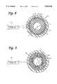
- FIG. 4is a partial cutaway view which shows the inner composite structure of a second embodiment of the invention.
- FIG. 5is a cross-sectional view of the second embodiment of the invention taken on section line 5--5 in FIG. 4;
- FIG. 6is an end-on view of the distal end of the catheter of the invention according to a third preferred embodiment of the invention.
- FIG. 7is an end-on view of the distal end of the catheter of the invention according to a fourth preferred embodiment of the invention.
- FIG. 8is a schematic illustration of a first embodiment of an electro-cautery device according to this invention.
- FIG. 9is a schematic illustration of a second embodiment of an electro-cautery device according to this invention.
- the catheter of the present inventionis designated generally by the reference numeral 10 in FIG. 1.
- the catheter 10is depicted with the central section broken away. Consequently, FIG. 1 gives no indication of the length of the catheter 10 relative to its width.
- the length of the catheter 10is selectable in accordance with the length of known catheters which are used for the same or similar applications.
- the catheter 10defines a proximal end 12, a distal end 14, and an outer surface 16, with the outer surface being approximately cylindrical in shape within local regions along the length of the catheter 10.
- the outer surface 16 of the catheter 10is defined by an outer electrically insulating surface layer 17 which fits snugly over an inner composite structure 18.
- polyurethaneis a preferable material for the outer insulating layer 17.
- polyester ether ketoneis a preferable material for the insulating layer 17 in ablative catheters.
- the outer surface layer 17, in this embodiment,is mechanically strippable at a selectable contact region 20 so as to expose the outer layer of the inner composite structure 18 over the selectable contact region 20.
- sensors 22 and 24are attached to selectable locations along the catheter 10, and sensor 26 is attached to the distal end 14.
- FIG. 2is a side view of a section of the catheter 10a with partial cutaway sections which reveal the inner composite structure 18a.
- FIG. 3provides a cross-sectional view of the catheter 10a.
- the catheter 10ais generally comprised of a central flexible, electrically non-conductive core 28 disposed along the catheter axis 30.
- the core 28is a solid electrical insulator, and in other embodiments the electrically insulative core 28 defines one or more hollow paths that extend between the proximal end 12 and the distal end 14 of the catheter 10a.
- the central non-conductive core 28is flexible electrically insulative tubing 32 which defines a central lumen 33 that extends along the catheter axis 30.
- the coreis made of polyurethane.
- the non-conductive core 28has a layer of stranded fibers 34 on its outer surface.
- Stranding optical fibers in a fiberoptic catheteris taught by Wardle et al. in U.S. Pat. No. 5,415,653 entitled "Optical Catheter with Stranded Fibers," and is hereby incorporated by reference in its entirety.
- the first layer of stranded fibers 34is comprised of a plurality of fibers, one of which is designated by reference numeral 36 in FIG. 3. Each fiber, such as fiber 36, in the layer of stranded fibers 34 extends substantially between the proximal end 12 and the distal end 14 of the catheter 10a, along non-overlapping, helical paths around the central non-conductive core 28.
- the stranded fibers 34define helical paths with a substantially uniform first pitch angle for all fibers 34 at substantially all points along the helical paths when the catheter 10a subtends a straight line and is in an unstressed, relaxed state.
- each individual fibersuch as fiber 36
- fiber 38may have a different thickness from that of fiber 36, or fiber 38 may be of a different material from that of fiber 36.
- the layer of stranded fibers 34is nowhere thicker than the thickness of the thickest fiber.
- the fibers 34are 40 ⁇ 4 electrically conducting wires which are all of approximately equal thickness.
- the example depicted in FIG. 3shows individual adjacent fibers, such as fibers 38 and 40, as being contiguous.
- Other embodiments of this inventioninclude selectable numbers of fibers within the layer of stranded fibers 34, and selectable separations between fibers.
- the number of fibersare chosen to be greater than 10, preferably 20 or more, and are often chosen in the range of 40, 50, or even greater.
- the fibersare preferably made from low resistance materials such as platinum, silver or titanium.
- the stranded fibers 34are covered by insulating layer 17 described above.
- FIG. 4is a side view of a section of the catheter 10b with partial cutaway sections which reveal the inner composite structure 18b.
- FIG. 5provides a cross-sectional view of the catheter 10b.
- the catheter 10bis generally comprised of a central flexible, electrically non-conductive core 28 disposed along the catheter axis 30, as described above in reference to the first mentioned preferred embodiment.
- This embodimenthas a first layer of stranded fibers 34 on the outer surface of the non-conductive core with a second layer of stranded fibers 42 immediately over the first layer of stranded fibers.
- each successive layer of fibersis stranded over the underlying layer in a direction opposite to that of the closest underlying stranded layer. Therefore, according to this preferred embodiment of the invention, the second layer of stranded fibers 42 is stranded over the first layer of stranded fibers 34 in a direction opposite to that of the first layer.
- the individual fibers of the second layer of stranded fibers 42, and any and all succeeding layers of stranded fibers,are selectable in material and thickness.
- the fibers of the first and second layers in this embodimentare preferably of materials with high tensile strength, such as stainless steel.
- the fibers of the second layer of stranded fibers 42similarly extend between the proximal end 12 and the distal end 14 of the catheter 10b along non-overlapping helical paths around the first layer of stranded fibers 34.
- the second layer of stranded fibers 42is also stranded such that the plurality of fibers define helical paths of a substantially uniform second pitch for all fibers 42 at substantially all points along the helical paths when the catheter 10b subtends a straight line and is in an unstressed, relaxed state. Since the second layer of stranded fibers 42 is stranded around the first layer of stranded fibers 34 in a direction opposite from that of the direction in which the first layer of stranded fibers 34 is stranded around the non-conductive core 28, the second pitch is opposite in sign to that of the first pitch.
- the magnitude of the second pitchis approximately equal to the magnitude of the first pitch, which is preferably 0.475 inches.
- the pitch of layers of stranded optical fiberscan be selectively varied to achieve alternative mechanical properties of a fiberoptic catheter. A greater pitch allows one to strand a greater number of fibers at the expense of some flexibility and torquability. Conversely, a smaller pitch leads to greater flexibility, but a smaller number of fibers in the strand.
- the pitchis much greater than the thickness of the wire (at least 10 times greater, and more typically more than 40 times greater).
- the preferred embodiment depicted by the example of FIGS. 4 and 5has a first electrically insulative layer 44 immediately covering the second layer of stranded fibers.
- Polyurethaneis a suitable material for layer 44 for most uses, or polyester ether ketone for other uses.
- a third layer of fibers 46is stranded over the outer surface defined by the first electrically insulative layer 44.
- the third layer of stranded fibers 46has 40 ⁇ 4 titanium wires, each of which extend substantially between the proximal end 12 and the distal end 14 of the catheter 10b, along non-overlapping helical paths with a third pitch which is substantially equal in magnitude, but opposite in sign to the second pitch.
- the third layer of stranded fibers 46is covered by a second layer of electrically insulative material 17 which defines an outer surface 16.
- the second layer of electrically insulative material 17must be capable of withstanding a DC voltage of 1500V applied in 20 ms pulses.
- a layer 17 made of polyurethane with a thickness of at least 0.0035 inchesis suitable for catheter 10b with an outer diameter of 0.077 ⁇ 0.002 inches.
- the outermost layer of stranded fibershas a large number of closely or maximally packed electrically conductive fibers.
- the fibersare arranged so as to approximate an electrically conductive cylindrical shell.
- the approximation to a cylindrical shellimproves as the number of fibers increases.
- small numbers of fiberscannot provide a good approximation to a cylindrical shell, as one can appreciate by considering the extreme cases of only one, two, three or four fibers.
- the central lumen of the non-conductive core 28is adapted to accommodate a plurality of fibers which, in one embodiment, extend between the proximal end 12 and the sensors 22, 24, and 26. More particularly, in a preferred embodiment, the central lumen of the non-conductive core 28 accommodates electrically conductive wires which extend from the proximal end 12 of the catheter 10b to connect to electrodes on the sensor 22, 24, and 26.
- the electrodes on sensor 26are suitable for mapping the electrical activity of the heart by procedures which are well-known to one skilled in the art of modern electrophysiology.
- the catheter 10is guided through a small incision in the body to the internal regions of interest.
- the flexible inner core 28, first layer of stranded fibers 34, second layer of stranded fibers 42, first insulating layer 44, third layer of stranded fibers 46, and outer surface layer 17all act in cooperation to transmit torque between the proximal end 12 and the distal end 14 in a manner known in the art for stranded optical fibers.
- the electrically conductive fibers of the third (outermost) layer of stranded fibers 46are electrically connected to a high voltage source, a radio frequency voltage source, signal detection and processing equipment, or other suitable electronic equipment.
- the contact region 20provides a suitably large surface area for making electrical contact with the internal region of the body of interest.
- the contact region 20is selectable in both size and location along the catheter 10 by stripping away the corresponding material from the electrically insulating surface layer 17.
- other embodiments of the instant inventionhave a plurality of contact regions, similar to contact region 20, which are also selectable in size and location. It is important to point out that, unlike prior art ring electrodes, the contact region 20 does not severely affect the flexibility of the catheter and does not present protruding obstacles.
- onemay connect a high voltage source to the third layer of stranded fibers 46 to deliver defibrillation pulses to a patient's heart through the contact region 20.
- the outer insulating layer 17 and the first electrically insulative layer 44ensure that the third layer of stranded fibers 46 is electrically isolated everywhere except at the proximal end 12 of the catheter 10, and at the contact region 20.
- the first layer of stranded fibers 34 and the second layer of stranded fibers 42are electrically isolated from the central lumen by the electrically insulating core 28, and from the third layer of stranded fibers 46 by the first insulative layer 44.
- the first layer of stranded fibers 34 and the second layer of stranded fibers 42have no electrical connections and thus provide primarily mechanical torque transfer properties.
- the first layer of stranded fibers 34 and the second layer of stranded fibers 42are electrically connected to ground as indicated schematically in FIG. 4 by the reference numeral 48.
- the layers 34 and 42provide a second layer in which electrical energy can be transferred between the proximal end 12 and distal end 14 of the catheter 10, independently of the third layer of stranded fibers 46. Energy transfer along this second channel can be in the form of signals from sensors, for example, or for therapeutic purposes.
- fibers of different materialscan be mixed with the electrically conductive fibers.
- fiber 50 in the third layer of stranded fibers 46, or fiber 40 of the first layer of stranded fiberscould be an optical fiber suited for transferring optical signals between the distal end 14 and the proximal end 12 of the catheter 10. A greater number of such optical fibers could be used as necessary.
- the optical fiberscould also be used to deliver therapeutic energy to a tissue site somewhere along the length, or at the distal end 14, of the catheter 10, in addition to the above described electrical energy transfer properties of the catheter 10.
- electrically insulative fiberscan be mixed with the electrically conductive fibers.
- the fiber labeled with the reference numeral 50may be an electrically conductive wire.
- the fiber 52may be an insulative fiber, fiber 54 conductive, fiber 56 insulative, and so on around the third layer of fibers 46.
- This embodimentyields a plurality of separate electrically conductive channels, e.g., fiber 50 would be one channel, fiber 54 another channel, and so on.
- This embodiment of the instant inventionis not limited to the one specific example described above. One could choose the numbers of electrically insulative and conductive fibers, and the specific configuration of those fibers, from among all of the possible permutations to suit the particular application.
- a fiber such as fiber 40 in the first layer of stranded fibers 34, and any number of other fibers in any of the stranded layerscan be made from certain polymers so as to enhance the lubricity of the corresponding layer.
- first layer of fibers 34is stranded over a central core 28, followed by a second layer of stranded fibers 42, a first layer of insulation 44, a third layer of stranded fibers 46, and finally an outer layer of insulation 17, does not limit the invention to that specific configuration.
- Other embodimentshave various numbers of layers of stranded fibers configured with various numbers of intervening electrically insulative layers.
- the stranded fiberscan be provided with an insulating or lubricious coating.
- the catheter of this inventionprovides a relatively large surface contact region for transferring electrical energy to an internal region of the body and it is also flexible at the contact region. There are no electrical connections between the contact regions and the wires that transfer the electrical energy to the contact regions, such as is the case with the prior art ring electrodes, thus, enhancing the reliability of the catheter. There are no complicated manufacturing techniques required to ensure that the contact region does not protrude beyond the diameter of the adjacent regions of the catheter, so as not to obstruct the motion of the catheter through narrow paths within the patient's body.
- the electrically conductive fiberscan be closely packed together, so as to approximate a cylindrical sheet conductor.
- a plurality of wires which carry an electrical current to the surface contact regionhas a lower overall resistance than a single wire of the same material of the same thickness that carries the same amount of current to contact regions. Therefore, the stranded wires allow the current to be spread over a region which approximates a cylindrical shell of current. As one strands wires closer together, one more closely approximates the limit of an electrically conductive cylindrical shell. This is particularly true when the wires are stranded so closely together that they are in contact with the immediately adjacent fibers. In such a case, if the wires do not have insulating outer layers, current can then also flow between wires. This additional degree of freedom for the flow of electrical current leads to an additional decrease in the overall electrical resistance, thus, even more closely approximating a conducting ring while remaining flexible.
- this inventionminimizes undesirable resistive heating effects while still providing a central lumen for other instruments and sensors, all while maintaining a compact, narrow cross-section.
- the catheter 10chas an outer insulating layer 17c, at least one layer of stranded fibers 34c comprising a plurality of electrically conductive wires, and a non-conductive core 28c which is preferably electrically insulative tubing 32c that defines a central lumen 33 (see FIG. 6).
- the plurality of electrically conductive wirescan have various configurations.
- the fibersare stranded in nonoverlapping helical paths in a manner as described in the first and second embodiments of this invention.
- all of the fibers of the layer of stranded fibers 34care preferably electrically conductive wires that have electrically insulating outer layers, such as outer layer 58.
- the electrically conductive wires of the layer of stranded fibers 34care preferably connected at the proximal end to a surgical electro-cautery power unit 35c (see, FIG. 8) such that each fiber has a polarity opposite to that of the two adjacent wires.
- the surgical electro-cautery power unitmay be selected from conventionally known power units to provide electrical pulses for cutting tissue.
- wire 62has a polarity opposite to that of wires 60 and 64.
- wire 64has a polarity opposite to that of wires 62 and 66, and so on around the entire periphery of the layer 34c of electrically conductive wires.
- electrically non-conductive fibersmay be included within the layer of stranded fibers 34c. Such non-conductive fibers may be disposed between electrically conductive wires within the layer of stranded fibers 34c in numerous configurations. In such alternative embodiments, the electrically non-conductive fibers may be disposed between electrically conductive wires to form configurations in which the electrically conductive wires are distributed about the catheter axis 30 in symmetrical and in asymmetrical patterns.
- the electrically conductive fibers within the layer of stranded fibers 34cdo not have electrically insulating surfaces. Instead, electrically insulating fibers, along with electrically insulating layers 17c and 32c, keep electrically conductive wires of one polarity electrically isolated from wires of the opposite polarity along the length of the catheter 10c.
- fibers 60, 64, and 68 in FIG. 6are electrically non-conductive
- fiber 62is an electrically conductive wire attached to the power source 35c at one polarity
- fiber 66is an electrically conductive wire with the polarity opposite to that of wire 62. This pattern is repeated around the entire layer of stranded fibers 34c.
- FIG. 6is an end-on view of the catheter 10c which illustrates the exposed ends of the wires 60, 62, 64, etc. which form the cutting end according to the third preferred embodiment.
- the cutting end of the layer of stranded fibers 34cis brought into contact with tissue to be cut. Electrical energy is transmitted through wires 60, 62, 64, etc. from the electro-cautery power unit at the proximal end of the catheter 10c to the cutting end at the distal end of the catheter 10c. An electrical current thus flows through tissue in contact with the tip and between wires of opposite polarities, e.g., wires 60 and 62.
- the relatively high resistance, or impedance, of the tissueresults in a rapid dissipation of energy in the tissue that is in contact with the tip.
- the rapid dissipation of energy in the tissueacts to a cut the tissue. Since all the fibers of the layer of stranded fibers 34c are electrically conductive wires, with electrically insulating surfaces, the cutting effect is approximately uniformly distributed around the cutting tip end of the layer of stranded fibers 34c.
- the catheter 10cis used for removing pacing leads for heart pacemakers which had previously been implanted in the patient's body.
- the surgeonslides the catheter 10c over the pacing lead such that the pacing lead extends along the central lumen 33. Since the cutting effect is approximately uniformly distributed around the cutting tip, the surgeon can advance the catheter 10c along the pacing lead in a substantially rectilinear motion without the need to rotate the catheter by large amounts about the catheter axis 30.
- some small angle "back and forth" rotations about the catheter axis 30 as the catheter 10c is advanced over the pacing leadcan be advantageous in some cases.
- this embodiment of the inventionpermits the surgeon to advance the catheter along the pacing lead while cutting scar tissue around the entire circumference of the lead, thus obviating the need to advance the catheter in a spiral motion over the pacing lead.
- this embodiment of the inventionwas described for removing pacing leads, this embodiment of the invention is also useful for other types of surgery, such as removing tumors, biopsies, and other implant devices.
- the catheter 10dhas a plurality of layers of stranded fibers.
- FIG. 7is an end-on view of the cutting tip at the distal end.
- the layer of stranded fibers 46dcorresponds to the layer of stranded fibers 34c of the third embodiment, thus providing the cutting action.
- the layers of stranded fibers 34d and 42dcorrespond to the layers of stranded fibers 34 and 42 of the second embodiment. Consequently, the additional layers of stranded fibers 34d and 42d provide the mechanical advantages of good maneuverability for a catheter for electro-cautery.
- substantially all fibers in the layer of stranded fibers 46dare electrically conductive wires which are in Electrical contact with each other.
- the layers of stranded fibers 34d and 42dare substantially all electrically conductive wires which are in electrical contact with the adjacent fibers.
- the layer 46dis connected at the proximal end to a surgical electro-cautery power unit 35d (see, FIG. 9) at one polarity while the layers 34d and 42d are connected at the opposite polarity.
- the layer 44dis an electrically non-conductive layer which keeps layer 46d electrically isolated from layers 34d and 44d along the length of the catheter.
- the layersare stranded in nonoverlapping helical paths in the same manner as in the second embodiment.
- the distal end of the catheteris brought into contact with tissue.
- the tissueprovides a conductive, but high resistance, or high impedance, path for electricity to flow between layer 46d and layers 34d and 42d at the distal end.
- the high resistance, or impedance, of the tissue in contact with the catheter 10d at its distal endresults in a rapid absorption of energy by the tissue which acts to provide the cutting effect.
- Catheters according to the fourth embodiment of the inventionmay be used according to the same method of pacing lead removal as described with respect to the third embodiment.
- this embodiment of the inventionis also useful for other types of surgery, such as removing tumors, biopsies, and other implant devices.
Landscapes
- Health & Medical Sciences (AREA)
- Engineering & Computer Science (AREA)
- Heart & Thoracic Surgery (AREA)
- Life Sciences & Earth Sciences (AREA)
- General Health & Medical Sciences (AREA)
- Veterinary Medicine (AREA)
- Nuclear Medicine, Radiotherapy & Molecular Imaging (AREA)
- Surgery (AREA)
- Cardiology (AREA)
- Animal Behavior & Ethology (AREA)
- Biomedical Technology (AREA)
- Public Health (AREA)
- Physics & Mathematics (AREA)
- Vascular Medicine (AREA)
- Plasma & Fusion (AREA)
- Otolaryngology (AREA)
- Radiology & Medical Imaging (AREA)
- Medical Informatics (AREA)
- Molecular Biology (AREA)
- Media Introduction/Drainage Providing Device (AREA)
- Surgical Instruments (AREA)
Abstract
Description
Claims (14)
Priority Applications (1)
| Application Number | Priority Date | Filing Date | Title |
|---|---|---|---|
| US08/873,753US5836946A (en) | 1996-06-12 | 1997-06-12 | Catheter for delivery of electric energy and a process for manufacturing same |
Applications Claiming Priority (2)
| Application Number | Priority Date | Filing Date | Title |
|---|---|---|---|
| US08/662,799US5824026A (en) | 1996-06-12 | 1996-06-12 | Catheter for delivery of electric energy and a process for manufacturing same |
| US08/873,753US5836946A (en) | 1996-06-12 | 1997-06-12 | Catheter for delivery of electric energy and a process for manufacturing same |
Related Parent Applications (1)
| Application Number | Title | Priority Date | Filing Date |
|---|---|---|---|
| US08/662,799Continuation-In-PartUS5824026A (en) | 1996-06-12 | 1996-06-12 | Catheter for delivery of electric energy and a process for manufacturing same |
Publications (1)
| Publication Number | Publication Date |
|---|---|
| US5836946Atrue US5836946A (en) | 1998-11-17 |
Family
ID=24659271
Family Applications (2)
| Application Number | Title | Priority Date | Filing Date |
|---|---|---|---|
| US08/662,799Expired - LifetimeUS5824026A (en) | 1996-06-12 | 1996-06-12 | Catheter for delivery of electric energy and a process for manufacturing same |
| US08/873,753Expired - LifetimeUS5836946A (en) | 1996-06-12 | 1997-06-12 | Catheter for delivery of electric energy and a process for manufacturing same |
Family Applications Before (1)
| Application Number | Title | Priority Date | Filing Date |
|---|---|---|---|
| US08/662,799Expired - LifetimeUS5824026A (en) | 1996-06-12 | 1996-06-12 | Catheter for delivery of electric energy and a process for manufacturing same |
Country Status (3)
| Country | Link |
|---|---|
| US (2) | US5824026A (en) |
| EP (2) | EP0812575B1 (en) |
| DE (1) | DE69740122D1 (en) |
Cited By (85)
| Publication number | Priority date | Publication date | Assignee | Title |
|---|---|---|---|---|
| US6183469B1 (en)* | 1997-08-27 | 2001-02-06 | Arthrocare Corporation | Electrosurgical systems and methods for the removal of pacemaker leads |
| US6419674B1 (en) | 1996-11-27 | 2002-07-16 | Cook Vascular Incorporated | Radio frequency dilator sheath |
| US20040068189A1 (en)* | 2002-02-28 | 2004-04-08 | Wilson Richard R. | Ultrasound catheter with embedded conductors |
| US20060089696A1 (en)* | 2004-10-21 | 2006-04-27 | Medtronic, Inc. | Implantable medical lead with reinforced outer jacket |
| US20060089691A1 (en)* | 2004-10-21 | 2006-04-27 | Medtronic, Inc. | Implantable medical lead with axially oriented coiled wire conductors |
| US20060089697A1 (en)* | 2004-10-21 | 2006-04-27 | Medtronic, Inc. | Implantable medical lead |
| US20060089695A1 (en)* | 2004-10-21 | 2006-04-27 | Medtronic, Inc. | Implantable medical lead with helical reinforcement |
| US20060089692A1 (en)* | 2004-10-21 | 2006-04-27 | Medtronic, Inc. | Implantable medical lead with stylet guide tube |
| US7087895B1 (en)* | 2003-06-07 | 2006-08-08 | Musc Foundation For Research Development | Electrospray ionization using pointed fibers |
| US20060178674A1 (en)* | 2005-02-08 | 2006-08-10 | Mcintyre John | Surgical apparatus having configurable portions |
| WO2006130056A1 (en)* | 2005-05-31 | 2006-12-07 | St. Jude Medical Ab | Implantable lead |
| US20070093802A1 (en)* | 2005-10-21 | 2007-04-26 | Danek Christopher J | Energy delivery devices and methods |
| WO2007022192A3 (en)* | 2005-08-15 | 2007-05-03 | Synecor Llc | Electrodes for implantable medical devices |
| US7384407B2 (en) | 2001-12-03 | 2008-06-10 | Ekos Corporation | Small vessel ultrasound catheter |
| US20080154345A1 (en)* | 2006-12-26 | 2008-06-26 | Spectranetics | Multi-Port Light Delivery Catheter And Methods For The Use Thereof |
| US7422585B1 (en) | 1992-01-07 | 2008-09-09 | Arthrocare Corporation | System for electrosurgical myocardial revascularization |
| US20080249515A1 (en)* | 2006-01-27 | 2008-10-09 | The Spectranetics Corporation | Interventional Devices and Methods For Laser Ablation |
| US7505812B1 (en) | 1993-05-10 | 2009-03-17 | Arthrocare Corporation | Electrosurgical system for treating restenosis of body lumens |
| US20090143651A1 (en)* | 2006-06-01 | 2009-06-04 | Bengt Kallback | Device for Invasive Use |
| WO2009072060A1 (en) | 2007-12-06 | 2009-06-11 | Koninklijke Philips Electronics N.V. | Apparatus, method and computer program for applying energy to an object |
| US20090171319A1 (en)* | 2007-12-30 | 2009-07-02 | Xiaoping Guo | Catheter Shaft with Multiple Reinforcing Layers and Method of its Manufacture |
| US20090166913A1 (en)* | 2007-12-30 | 2009-07-02 | Xiaoping Guo | Catheter Shaft and Method of its Manufacture |
| WO2009085486A1 (en)* | 2007-12-30 | 2009-07-09 | St. Jude Medical, Atrial Fibrillation Division, Inc. | Catheter shaft with multiple reinforcing layers and method of its manufacture |
| WO2009072039A3 (en)* | 2007-12-06 | 2009-07-23 | Koninkl Philips Electronics Nv | Apparatus, method and computer program for applying energy to an object |
| US7571010B2 (en) | 2005-05-06 | 2009-08-04 | Cardiac Pacemakers, Inc. | Cable electrode assembly for a lead terminal and method therefor |
| US20090198221A1 (en)* | 2004-09-17 | 2009-08-06 | The Spectranetics Corporation | Apparatus and methods for directional delivery of laser energy |
| US20090254074A1 (en)* | 2008-04-02 | 2009-10-08 | Spectranetics | Liquid light-guide catheter with optically diverging tip |
| US20100016842A1 (en)* | 2008-07-21 | 2010-01-21 | Spectranetics | Tapered Liquid Light Guide |
| US20100152720A1 (en)* | 2008-12-12 | 2010-06-17 | Spectranetics | Offset catheter |
| US20100152717A1 (en)* | 2008-12-17 | 2010-06-17 | Spectranetics | Eccentric balloon laser catheter |
| US20100168731A1 (en)* | 2008-12-31 | 2010-07-01 | Ardian, Inc. | Apparatus, systems, and methods for achieving intravascular, thermally-induced renal neuromodulation |
| US20100168739A1 (en)* | 2008-12-31 | 2010-07-01 | Ardian, Inc. | Apparatus, systems, and methods for achieving intravascular, thermally-induced renal neuromodulation |
| US7771372B2 (en) | 2003-01-03 | 2010-08-10 | Ekos Corporation | Ultrasonic catheter with axial energy field |
| US7853331B2 (en) | 2004-11-05 | 2010-12-14 | Asthmatx, Inc. | Medical device with procedure improvement features |
| US20100324472A1 (en)* | 2007-11-14 | 2010-12-23 | Pathway Medical Technologies, Inc. | Delivery and administration of compositions using interventional catheters |
| US20110009750A1 (en)* | 2004-09-17 | 2011-01-13 | Spectranetics | Cardiovascular imaging system |
| US7931647B2 (en) | 2006-10-20 | 2011-04-26 | Asthmatx, Inc. | Method of delivering energy to a lung airway using markers |
| US7949407B2 (en) | 2004-11-05 | 2011-05-24 | Asthmatx, Inc. | Energy delivery devices and methods |
| US7963925B1 (en) | 2005-01-26 | 2011-06-21 | Schecter Stuart O | Method and apparatus for defining the effect of atrial arrhythmias on cardiac performance and directing therapy using a plurality of intrinsically and extrinsically derived signals |
| US7993308B2 (en) | 2003-04-22 | 2011-08-09 | Ekos Corporation | Ultrasound enhanced central venous catheter |
| US20120116158A1 (en)* | 2008-07-08 | 2012-05-10 | Hale Eric L | Wide Angle Flexible Endoscope |
| US8235983B2 (en) | 2007-07-12 | 2012-08-07 | Asthmatx, Inc. | Systems and methods for delivering energy to passageways in a patient |
| US20120310241A1 (en)* | 2011-05-31 | 2012-12-06 | Tyco Healthcare Group Lp | Electrosurgical Apparatus with Tissue Site Sensing and Feedback Control |
| US20130053838A1 (en)* | 2011-08-22 | 2013-02-28 | William T. Kuo | Interventional radiologic devices and methods for embedded filter removal |
| WO2013043924A3 (en)* | 2011-09-20 | 2013-06-27 | Bsd Medical Corporation | Ablation antenna |
| US8628519B2 (en) | 2004-09-17 | 2014-01-14 | The Spectranetics Corporation | Rapid exchange bias laser catheter design |
| US8663122B2 (en) | 2005-01-26 | 2014-03-04 | Stuart Schecter LLC | Cardiovascular haptic handle system |
| EP2789366A1 (en)* | 2013-04-11 | 2014-10-15 | Biosense Webster (Israel), Ltd. | High density electrode structure |
| US8942828B1 (en) | 2011-04-13 | 2015-01-27 | Stuart Schecter, LLC | Minimally invasive cardiovascular support system with true haptic coupling |
| US9101374B1 (en) | 2012-08-07 | 2015-08-11 | David Harris Hoch | Method for guiding an ablation catheter based on real time intracardiac electrical signals and apparatus for performing the method |
| US9125661B2 (en) | 2002-04-08 | 2015-09-08 | Medtronic Ardian Luxembourg S.A.R.L. | Methods and apparatus for renal neuromodulation |
| US9131978B2 (en) | 2002-04-08 | 2015-09-15 | Medtronic Ardian Luxembourg S.A.R.L. | Methods for bilateral renal neuromodulation |
| CN105263557A (en)* | 2013-06-07 | 2016-01-20 | 导管治疗有限公司 | An electrical lead for a catheter and method of manufacturing |
| EP2992926A1 (en)* | 2002-01-29 | 2016-03-09 | Medtronic, Inc. | Method and apparatus for shielding against mri disturbances |
| US9289173B2 (en) | 2007-11-09 | 2016-03-22 | The Spectranetics Corporation | Intra-vascular device with pressure detection capabilities using pressure sensitive material |
| USD775728S1 (en) | 2015-07-02 | 2017-01-03 | The Spectranetics Corporation | Medical device handle |
| US9623211B2 (en) | 2013-03-13 | 2017-04-18 | The Spectranetics Corporation | Catheter movement control |
| WO2017087149A1 (en)* | 2015-11-18 | 2017-05-26 | Heraeus Deutschland GmbH & Co. KG | Signal and torque transmitting torque coil |
| JP2017520324A (en)* | 2014-07-01 | 2017-07-27 | ボストン サイエンティフィック サイムド,インコーポレイテッドBoston Scientific Scimed,Inc. | Multilayer braid end |
| US9757200B2 (en) | 2013-03-14 | 2017-09-12 | The Spectranetics Corporation | Intelligent catheter |
| US9814618B2 (en) | 2013-06-06 | 2017-11-14 | Boston Scientific Scimed, Inc. | Devices for delivering energy and related methods of use |
| US9848952B2 (en) | 2007-10-24 | 2017-12-26 | The Spectranetics Corporation | Liquid light guide catheter having biocompatible liquid light guide medium |
| US9907614B2 (en) | 2014-10-29 | 2018-03-06 | The Spectranetics Corporation | Laser energy delivery devices including laser transmission detection systems and methods |
| US10013082B2 (en) | 2012-06-05 | 2018-07-03 | Stuart Schecter, LLC | Operating system with haptic interface for minimally invasive, hand-held surgical instrument |
| US10092169B2 (en) | 2008-07-08 | 2018-10-09 | Karl Storz Imaging, Inc. | Solid state variable direction of view endoscope |
| WO2019055635A1 (en)* | 2017-09-14 | 2019-03-21 | St. Jude Medical, Cardiology Division, Inc. | Torqueable steerable sheaths |
| US10492863B2 (en) | 2014-10-29 | 2019-12-03 | The Spectranetics Corporation | Laser energy delivery devices including laser transmission detection systems and methods |
| US10575743B2 (en) | 2013-04-11 | 2020-03-03 | Biosense Webster (Israel) Ltd. | High electrode density basket catheter |
| US10646274B2 (en) | 2014-12-30 | 2020-05-12 | Regents Of The University Of Minnesota | Laser catheter with use of reflected light and force indication to determine material type in vascular system |
| US10646275B2 (en) | 2014-12-30 | 2020-05-12 | Regents Of The University Of Minnesota | Laser catheter with use of determined material type in vascular system in ablation of material |
| US10646118B2 (en) | 2014-12-30 | 2020-05-12 | Regents Of The University Of Minnesota | Laser catheter with use of reflected light to determine material type in vascular system |
| US10758308B2 (en) | 2013-03-14 | 2020-09-01 | The Spectranetics Corporation | Controller to select optical channel parameters in a catheter |
| US10765473B2 (en) | 2010-11-08 | 2020-09-08 | Baylis Medical Company Inc. | Electrosurgical device having a lumen |
| US10772683B2 (en) | 2014-05-18 | 2020-09-15 | Eximo Medical Ltd. | System for tissue ablation using pulsed laser |
| IL237208B (en)* | 2014-03-05 | 2021-01-31 | Thomas Beeckler Christopher | Multi-arm catheter with signal transmission over braid wires |
| US10987168B2 (en) | 2014-05-29 | 2021-04-27 | Spectranetics Llc | System and method for coordinated laser delivery and imaging |
| US10987167B2 (en) | 2008-11-05 | 2021-04-27 | The Spectranetics Corporation | Biasing laser catheter: monorail design |
| US11576724B2 (en) | 2011-02-24 | 2023-02-14 | Eximo Medical Ltd. | Hybrid catheter for vascular intervention |
| US11642169B2 (en) | 2013-03-14 | 2023-05-09 | The Spectranetics Corporation | Smart multiplexed medical laser system |
| US11666251B2 (en) | 2016-10-31 | 2023-06-06 | Heraeus Deutschland GmbH & Co. KG | Signal and torque transmitting torque coil |
| US11684420B2 (en) | 2016-05-05 | 2023-06-27 | Eximo Medical Ltd. | Apparatus and methods for resecting and/or ablating an undesired tissue |
| US11937873B2 (en) | 2013-03-12 | 2024-03-26 | Boston Scientific Medical Device Limited | Electrosurgical device having a lumen |
| US12038322B2 (en) | 2022-06-21 | 2024-07-16 | Eximo Medical Ltd. | Devices and methods for testing ablation systems |
| US12251159B2 (en) | 2013-03-12 | 2025-03-18 | Boston Scientific Medical Device Limited | Medical device having a support structure |
| US12376904B1 (en) | 2020-09-08 | 2025-08-05 | Angiodynamics, Inc. | Dynamic laser stabilization and calibration system |
Families Citing this family (88)
| Publication number | Priority date | Publication date | Assignee | Title |
|---|---|---|---|---|
| US6047700A (en) | 1998-03-30 | 2000-04-11 | Arthrocare Corporation | Systems and methods for electrosurgical removal of calcified deposits |
| US6238340B1 (en)* | 1998-05-19 | 2001-05-29 | Eckhard Alt | Composite materials for avoidance of unwanted radiation amplification |
| US8244370B2 (en)* | 2001-04-13 | 2012-08-14 | Greatbatch Ltd. | Band stop filter employing a capacitor and an inductor tank circuit to enhance MRI compatibility of active medical devices |
| US6216045B1 (en) | 1999-04-26 | 2001-04-10 | Advanced Neuromodulation Systems, Inc. | Implantable lead and method of manufacture |
| US6304784B1 (en)* | 1999-06-15 | 2001-10-16 | Arizona Board Of Regents, Acting For And On Behalf Of Arizona State University | Flexible probing device and methods for manufacturing the same |
| US7149585B2 (en)* | 2001-03-30 | 2006-12-12 | Micronet Medical, Inc. | Lead body and method of lead body construction |
| US7555349B2 (en)* | 2000-09-26 | 2009-06-30 | Advanced Neuromodulation Systems, Inc. | Lead body and method of lead body construction |
| WO2002083016A1 (en) | 2001-04-13 | 2002-10-24 | Surgi-Vision, Inc. | Systems and methods for magnetic-resonance-guided interventional procedures |
| US9295828B2 (en) | 2001-04-13 | 2016-03-29 | Greatbatch Ltd. | Self-resonant inductor wound portion of an implantable lead for enhanced MRI compatibility of active implantable medical devices |
| US7162303B2 (en) | 2002-04-08 | 2007-01-09 | Ardian, Inc. | Renal nerve stimulation method and apparatus for treatment of patients |
| US6978174B2 (en) | 2002-04-08 | 2005-12-20 | Ardian, Inc. | Methods and devices for renal nerve blocking |
| US8175711B2 (en) | 2002-04-08 | 2012-05-08 | Ardian, Inc. | Methods for treating a condition or disease associated with cardio-renal function |
| US8145317B2 (en) | 2002-04-08 | 2012-03-27 | Ardian, Inc. | Methods for renal neuromodulation |
| US8145316B2 (en) | 2002-04-08 | 2012-03-27 | Ardian, Inc. | Methods and apparatus for renal neuromodulation |
| US7853333B2 (en) | 2002-04-08 | 2010-12-14 | Ardian, Inc. | Methods and apparatus for multi-vessel renal neuromodulation |
| US8131371B2 (en) | 2002-04-08 | 2012-03-06 | Ardian, Inc. | Methods and apparatus for monopolar renal neuromodulation |
| US7620451B2 (en) | 2005-12-29 | 2009-11-17 | Ardian, Inc. | Methods and apparatus for pulsed electric field neuromodulation via an intra-to-extravascular approach |
| US20040082859A1 (en) | 2002-07-01 | 2004-04-29 | Alan Schaer | Method and apparatus employing ultrasound energy to treat body sphincters |
| AU2002952146A0 (en)* | 2002-10-17 | 2002-10-31 | Cochlear Limited | Stretchable conducting lead |
| US6920361B2 (en)* | 2003-02-14 | 2005-07-19 | Medtronic, Inc. | Reverse wound electrodes |
| US20050027339A1 (en)* | 2003-07-29 | 2005-02-03 | Micronet Medical, Inc. | System and method for providing a medical lead body |
| US20050027340A1 (en)* | 2003-07-29 | 2005-02-03 | Micronet Medical, Inc. | System and method for providing a medical lead body having dual conductor layers |
| US20050027341A1 (en)* | 2003-07-29 | 2005-02-03 | Micronet Medical, Inc. | System and method for providing a medical lead body having conductors that are wound in opposite directions |
| US8147486B2 (en) | 2003-09-22 | 2012-04-03 | St. Jude Medical, Atrial Fibrillation Division, Inc. | Medical device with flexible printed circuit |
| US7234225B2 (en)* | 2003-09-22 | 2007-06-26 | St. Jude Medical, Atrial Fibrillation Division, Inc. | Method for manufacturing medical device having embedded traces and formed electrodes |
| US7229437B2 (en)* | 2003-09-22 | 2007-06-12 | St. Jude Medical, Atrial Fibrillation Division, Inc. | Medical device having integral traces and formed electrodes |
| US7922654B2 (en) | 2004-08-09 | 2011-04-12 | Boston Scientific Scimed, Inc. | Fiber optic imaging catheter |
| ES2552252T3 (en)* | 2004-03-23 | 2015-11-26 | Boston Scientific Limited | Live View System |
| US11819192B2 (en) | 2004-03-23 | 2023-11-21 | Boston Scientific Scimed, Inc. | In-vivo visualization system |
| US20060282112A1 (en)* | 2005-06-09 | 2006-12-14 | Stephen Griffin | Method and apparatus for enhanced electrolytic detachment |
| US7901441B2 (en) | 2005-10-18 | 2011-03-08 | Boston Scientific Scimed, Inc. | Method of using an imaging catheter to conduct photodynamic procedures |
| DE102006029864A1 (en)* | 2006-06-28 | 2008-01-03 | Biotronik Crm Patent Ag | Electrode device for electrodascularosis and / or therapy |
| WO2008051122A1 (en)* | 2006-10-25 | 2008-05-02 | St. Jude Medical Ab | A medical implantable lead |
| US9028520B2 (en) | 2006-12-22 | 2015-05-12 | The Spectranetics Corporation | Tissue separating systems and methods |
| US8961551B2 (en) | 2006-12-22 | 2015-02-24 | The Spectranetics Corporation | Retractable separating systems and methods |
| US10080889B2 (en) | 2009-03-19 | 2018-09-25 | Greatbatch Ltd. | Low inductance and low resistance hermetically sealed filtered feedthrough for an AIMD |
| US9108066B2 (en) | 2008-03-20 | 2015-08-18 | Greatbatch Ltd. | Low impedance oxide resistant grounded capacitor for an AIMD |
| US20090270956A1 (en)* | 2008-04-25 | 2009-10-29 | Pacesetter, Inc. | Implantable medical lead configured for improved mri safety |
| US8244375B2 (en)* | 2008-08-25 | 2012-08-14 | Pacesetter, Inc. | MRI compatible lead |
| US20100114275A1 (en)* | 2008-10-30 | 2010-05-06 | Pacesetter, Inc. | Implantable medical lead including winding for improved mri safety |
| WO2010080886A1 (en) | 2009-01-09 | 2010-07-15 | Recor Medical, Inc. | Methods and apparatus for treatment of mitral valve in insufficiency |
| US9084883B2 (en)* | 2009-03-12 | 2015-07-21 | Cardiac Pacemakers, Inc. | Thin profile conductor assembly for medical device leads |
| US9254380B2 (en)* | 2009-10-19 | 2016-02-09 | Cardiac Pacemakers, Inc. | MRI compatible tachycardia lead |
| KR101673574B1 (en) | 2009-10-30 | 2016-11-07 | 레코 메디컬, 인코포레이티드 | Method and apparatus for treatment of hypertension through percutaneous ultrasound renal denervation |
| US9750944B2 (en) | 2009-12-30 | 2017-09-05 | Cardiac Pacemakers, Inc. | MRI-conditionally safe medical device lead |
| US8391994B2 (en) | 2009-12-31 | 2013-03-05 | Cardiac Pacemakers, Inc. | MRI conditionally safe lead with low-profile multi-layer conductor for longitudinal expansion |
| WO2011081713A1 (en) | 2009-12-31 | 2011-07-07 | Cardiac Pacemakers, Inc. | Mri conditionally safe lead with multi-layer conductor |
| US8825181B2 (en) | 2010-08-30 | 2014-09-02 | Cardiac Pacemakers, Inc. | Lead conductor with pitch and torque control for MRI conditionally safe use |
| US9427596B2 (en) | 2013-01-16 | 2016-08-30 | Greatbatch Ltd. | Low impedance oxide resistant grounded capacitor for an AIMD |
| US10350421B2 (en) | 2013-06-30 | 2019-07-16 | Greatbatch Ltd. | Metallurgically bonded gold pocket pad for grounding an EMI filter to a hermetic terminal for an active implantable medical device |
| US11198014B2 (en) | 2011-03-01 | 2021-12-14 | Greatbatch Ltd. | Hermetically sealed filtered feedthrough assembly having a capacitor with an oxide resistant electrical connection to an active implantable medical device housing |
| US10272252B2 (en) | 2016-11-08 | 2019-04-30 | Greatbatch Ltd. | Hermetic terminal for an AIMD having a composite brazed conductive lead |
| US9931514B2 (en) | 2013-06-30 | 2018-04-03 | Greatbatch Ltd. | Low impedance oxide resistant grounded capacitor for an AIMD |
| US10596369B2 (en) | 2011-03-01 | 2020-03-24 | Greatbatch Ltd. | Low equivalent series resistance RF filter for an active implantable medical device |
| US9245668B1 (en)* | 2011-06-29 | 2016-01-26 | Cercacor Laboratories, Inc. | Low noise cable providing communication between electronic sensor components and patient monitor |
| AU2013249088B2 (en) | 2012-04-20 | 2015-12-03 | Cardiac Pacemakers, Inc. | Implantable medical device lead including a unifilar coiled cable |
| US8954168B2 (en) | 2012-06-01 | 2015-02-10 | Cardiac Pacemakers, Inc. | Implantable device lead including a distal electrode assembly with a coiled component |
| JP6069499B2 (en) | 2012-08-31 | 2017-02-01 | カーディアック ペースメイカーズ, インコーポレイテッド | Lead wire with low peak MRI heating |
| US9413896B2 (en) | 2012-09-14 | 2016-08-09 | The Spectranetics Corporation | Tissue slitting methods and systems |
| US8983623B2 (en) | 2012-10-18 | 2015-03-17 | Cardiac Pacemakers, Inc. | Inductive element for providing MRI compatibility in an implantable medical device lead |
| US10260181B2 (en) | 2013-01-14 | 2019-04-16 | Lake Region Medical, Inc. | Directional mesh and associated systems |
| USRE46699E1 (en) | 2013-01-16 | 2018-02-06 | Greatbatch Ltd. | Low impedance oxide resistant grounded capacitor for an AIMD |
| US10383691B2 (en) | 2013-03-13 | 2019-08-20 | The Spectranetics Corporation | Last catheter with helical internal lumen |
| US9456872B2 (en) | 2013-03-13 | 2016-10-04 | The Spectranetics Corporation | Laser ablation catheter |
| US9283040B2 (en) | 2013-03-13 | 2016-03-15 | The Spectranetics Corporation | Device and method of ablative cutting with helical tip |
| US9291663B2 (en) | 2013-03-13 | 2016-03-22 | The Spectranetics Corporation | Alarm for lead insulation abnormality |
| US9883885B2 (en) | 2013-03-13 | 2018-02-06 | The Spectranetics Corporation | System and method of ablative cutting and pulsed vacuum aspiration |
| US10835279B2 (en) | 2013-03-14 | 2020-11-17 | Spectranetics Llc | Distal end supported tissue slitting apparatus |
| WO2014159276A1 (en) | 2013-03-14 | 2014-10-02 | Recor Medical, Inc. | Ultrasound-based neuromodulation system |
| US10842532B2 (en) | 2013-03-15 | 2020-11-24 | Spectranetics Llc | Medical device for removing an implanted object |
| WO2014151814A1 (en) | 2013-03-15 | 2014-09-25 | The Spectranetics Corporation | Surgical instrument for removing an implanted object |
| US10448999B2 (en) | 2013-03-15 | 2019-10-22 | The Spectranetics Corporation | Surgical instrument for removing an implanted object |
| US9918737B2 (en) | 2013-03-15 | 2018-03-20 | The Spectranetics Corporation | Medical device for removing an implanted object |
| US9980743B2 (en) | 2013-03-15 | 2018-05-29 | The Spectranetics Corporation | Medical device for removing an implanted object using laser cut hypotubes |
| US9668765B2 (en) | 2013-03-15 | 2017-06-06 | The Spectranetics Corporation | Retractable blade for lead removal device |
| WO2015130753A1 (en) | 2014-02-26 | 2015-09-03 | Cardiac Pacemakers, Inc | Construction of an mri-safe tachycardia lead |
| US12053203B2 (en) | 2014-03-03 | 2024-08-06 | Spectranetics, Llc | Multiple configuration surgical cutting device |
| EP3113701B1 (en) | 2014-03-03 | 2020-07-22 | The Spectranetics Corporation | Multiple configuration surgical cutting device |
| CN106232043B (en)* | 2014-04-24 | 2019-07-23 | 美敦力阿迪安卢森堡有限公司 | Nerve modulation conduit and relevant system and method with braiding axle |
| US10405924B2 (en) | 2014-05-30 | 2019-09-10 | The Spectranetics Corporation | System and method of ablative cutting and vacuum aspiration through primary orifice and auxiliary side port |
| USD765243S1 (en) | 2015-02-20 | 2016-08-30 | The Spectranetics Corporation | Medical device handle |
| USD770616S1 (en) | 2015-02-20 | 2016-11-01 | The Spectranetics Corporation | Medical device handle |
| GB2565488A (en) | 2016-09-30 | 2019-02-13 | Halliburton Energy Services Inc | Laser induced graphene coated optical fibers |
| US10249415B2 (en) | 2017-01-06 | 2019-04-02 | Greatbatch Ltd. | Process for manufacturing a leadless feedthrough for an active implantable medical device |
| US10912945B2 (en) | 2018-03-22 | 2021-02-09 | Greatbatch Ltd. | Hermetic terminal for an active implantable medical device having a feedthrough capacitor partially overhanging a ferrule for high effective capacitance area |
| US10905888B2 (en) | 2018-03-22 | 2021-02-02 | Greatbatch Ltd. | Electrical connection for an AIMD EMI filter utilizing an anisotropic conductive layer |
| CN111905236A (en)* | 2020-09-03 | 2020-11-10 | 青岛博泰医疗器械有限责任公司 | Drug balloon catheter system |
| WO2024160553A1 (en)* | 2023-02-01 | 2024-08-08 | Vascomed Gmbh | Catheter and system comprising the catheter and an introducer sheath |
Citations (4)
| Publication number | Priority date | Publication date | Assignee | Title |
|---|---|---|---|---|
| US4559951A (en)* | 1982-11-29 | 1985-12-24 | Cardiac Pacemakers, Inc. | Catheter assembly |
| US4840186A (en)* | 1987-06-01 | 1989-06-20 | Siemens Aktiengesellschaft | Implantable multi-pole coaxial lead |
| US5330520A (en)* | 1986-05-15 | 1994-07-19 | Telectronics Pacing Systems, Inc. | Implantable electrode and sensor lead apparatus |
| US5483022A (en)* | 1994-04-12 | 1996-01-09 | Ventritex, Inc. | Implantable conductor coil formed from cabled composite wire |
Family Cites Families (22)
| Publication number | Priority date | Publication date | Assignee | Title |
|---|---|---|---|---|
| DE3134896C2 (en)* | 1981-09-03 | 1985-03-28 | W.C. Heraeus Gmbh, 6450 Hanau | Cable feed for pacemaker electrodes |
| JPH066115B2 (en)* | 1987-08-27 | 1994-01-26 | 新技術事業団 | Electrodes for implantation in the body |
| EP0312495A3 (en)* | 1987-10-16 | 1989-08-30 | Institut Straumann Ag | Electrical cable for carrying out at least one stimulation and/or measurement in a human or animal body |
| US4981478A (en)* | 1988-09-06 | 1991-01-01 | Advanced Cardiovascular Systems | Composite vascular catheter |
| US5016646A (en)* | 1988-11-29 | 1991-05-21 | Telectronics, N.V. | Thin electrode lead and connections |
| US5005587A (en)* | 1989-11-13 | 1991-04-09 | Pacing Systems, Inc. | Braid Electrode leads and catheters and methods for using the same |
| US5569220A (en)* | 1991-01-24 | 1996-10-29 | Cordis Webster, Inc. | Cardiovascular catheter having high torsional stiffness |
| US5209229A (en)* | 1991-05-20 | 1993-05-11 | Telectronics Pacing Systems, Inc. | Apparatus and method employing plural electrode configurations for cardioversion of atrial fibrillation in an arrhythmia control system |
| US5246014A (en)* | 1991-11-08 | 1993-09-21 | Medtronic, Inc. | Implantable lead system |
| US5324326A (en)* | 1991-11-25 | 1994-06-28 | Telectronics Pacing Systems, Inc. | Pressure sensing pacing lead |
| US5330521A (en)* | 1992-06-29 | 1994-07-19 | Cohen Donald M | Low resistance implantable electrical leads |
| EP0656766A4 (en)* | 1992-08-26 | 1995-09-27 | Advanced Interventional System | Optical catheter with stranded fibers. |
| US5324323A (en)* | 1992-09-09 | 1994-06-28 | Telectronics Pacing Systems, Inc. | Multiple channel cardiosynchronous myoplasty apparatus |
| US5466252A (en)* | 1992-10-02 | 1995-11-14 | W. L. Gore & Associates, Inc. | Implantable lead |
| US5303704A (en)* | 1992-12-22 | 1994-04-19 | Medtronic, Inc. | Medical electrical lead |
| US5706809A (en)* | 1993-01-29 | 1998-01-13 | Cardima, Inc. | Method and system for using multiple intravascular sensing devices to detect electrical activity |
| US5524619A (en)* | 1993-04-01 | 1996-06-11 | Terumo Kabushiki Kaisha | Multielectrode probe |
| DE4428914C2 (en)* | 1993-08-18 | 2000-09-28 | Scimed Life Systems Inc | Thin-walled multi-layer catheter |
| US5417208A (en)* | 1993-10-12 | 1995-05-23 | Arrow International Investment Corp. | Electrode-carrying catheter and method of making same |
| US5443492A (en)* | 1994-02-02 | 1995-08-22 | Medtronic, Inc. | Medical electrical lead and introducer system for implantable pulse generator |
| US5423881A (en)* | 1994-03-14 | 1995-06-13 | Medtronic, Inc. | Medical electrical lead |
| US5667499A (en)* | 1994-10-04 | 1997-09-16 | Scimed Life Systems, Inc. | Guide catheter unibody |
- 1996
- 1996-06-12USUS08/662,799patent/US5824026A/ennot_activeExpired - Lifetime
- 1997
- 1997-06-11EPEP97109491Apatent/EP0812575B1/ennot_activeExpired - Lifetime
- 1997-06-11EPEP05010062Apatent/EP1598024A3/ennot_activeWithdrawn
- 1997-06-11DEDE69740122Tpatent/DE69740122D1/ennot_activeExpired - Lifetime
- 1997-06-12USUS08/873,753patent/US5836946A/ennot_activeExpired - Lifetime
Patent Citations (4)
| Publication number | Priority date | Publication date | Assignee | Title |
|---|---|---|---|---|
| US4559951A (en)* | 1982-11-29 | 1985-12-24 | Cardiac Pacemakers, Inc. | Catheter assembly |
| US5330520A (en)* | 1986-05-15 | 1994-07-19 | Telectronics Pacing Systems, Inc. | Implantable electrode and sensor lead apparatus |
| US4840186A (en)* | 1987-06-01 | 1989-06-20 | Siemens Aktiengesellschaft | Implantable multi-pole coaxial lead |
| US5483022A (en)* | 1994-04-12 | 1996-01-09 | Ventritex, Inc. | Implantable conductor coil formed from cabled composite wire |
Cited By (164)
| Publication number | Priority date | Publication date | Assignee | Title |
|---|---|---|---|---|
| US7422585B1 (en) | 1992-01-07 | 2008-09-09 | Arthrocare Corporation | System for electrosurgical myocardial revascularization |
| US7505812B1 (en) | 1993-05-10 | 2009-03-17 | Arthrocare Corporation | Electrosurgical system for treating restenosis of body lumens |
| US6419674B1 (en) | 1996-11-27 | 2002-07-16 | Cook Vascular Incorporated | Radio frequency dilator sheath |
| US6379351B1 (en)* | 1997-08-27 | 2002-04-30 | Arthrocare Corporation | Electrosurgical method for the removal of pacemaker leads |
| US6183469B1 (en)* | 1997-08-27 | 2001-02-06 | Arthrocare Corporation | Electrosurgical systems and methods for the removal of pacemaker leads |
| US7384407B2 (en) | 2001-12-03 | 2008-06-10 | Ekos Corporation | Small vessel ultrasound catheter |
| EP2992926A1 (en)* | 2002-01-29 | 2016-03-09 | Medtronic, Inc. | Method and apparatus for shielding against mri disturbances |
| US20040068189A1 (en)* | 2002-02-28 | 2004-04-08 | Wilson Richard R. | Ultrasound catheter with embedded conductors |
| US7774933B2 (en) | 2002-02-28 | 2010-08-17 | Ekos Corporation | Method of manufacturing ultrasound catheters |
| US9131978B2 (en) | 2002-04-08 | 2015-09-15 | Medtronic Ardian Luxembourg S.A.R.L. | Methods for bilateral renal neuromodulation |
| US9125661B2 (en) | 2002-04-08 | 2015-09-08 | Medtronic Ardian Luxembourg S.A.R.L. | Methods and apparatus for renal neuromodulation |
| US7771372B2 (en) | 2003-01-03 | 2010-08-10 | Ekos Corporation | Ultrasonic catheter with axial energy field |
| US7993308B2 (en) | 2003-04-22 | 2011-08-09 | Ekos Corporation | Ultrasound enhanced central venous catheter |
| US7087895B1 (en)* | 2003-06-07 | 2006-08-08 | Musc Foundation For Research Development | Electrospray ionization using pointed fibers |
| US10959699B2 (en) | 2004-09-17 | 2021-03-30 | The Spectranetics Corporation | Cardiovascular imaging system |
| US10111709B2 (en) | 2004-09-17 | 2018-10-30 | The Spectranetics Corporation | Rapid exchange bias laser catheter design |
| US8545488B2 (en) | 2004-09-17 | 2013-10-01 | The Spectranetics Corporation | Cardiovascular imaging system |
| US8628519B2 (en) | 2004-09-17 | 2014-01-14 | The Spectranetics Corporation | Rapid exchange bias laser catheter design |
| US20110009750A1 (en)* | 2004-09-17 | 2011-01-13 | Spectranetics | Cardiovascular imaging system |
| US20090198221A1 (en)* | 2004-09-17 | 2009-08-06 | The Spectranetics Corporation | Apparatus and methods for directional delivery of laser energy |
| US9308047B2 (en) | 2004-09-17 | 2016-04-12 | The Spectranetics Corporation | Rapid exchange bias laser catheter design |
| US7846153B2 (en) | 2004-09-17 | 2010-12-07 | The Spectranetics Corporation | Apparatus and methods for directional delivery of laser energy |
| WO2006047168A1 (en)* | 2004-10-21 | 2006-05-04 | Medtronic, Inc. | Implantable medical lead with stylet guide tube |
| US7831311B2 (en)* | 2004-10-21 | 2010-11-09 | Medtronic, Inc. | Reduced axial stiffness implantable medical lead |
| US7519432B2 (en) | 2004-10-21 | 2009-04-14 | Medtronic, Inc. | Implantable medical lead with helical reinforcement |
| US20060089696A1 (en)* | 2004-10-21 | 2006-04-27 | Medtronic, Inc. | Implantable medical lead with reinforced outer jacket |
| US20060089691A1 (en)* | 2004-10-21 | 2006-04-27 | Medtronic, Inc. | Implantable medical lead with axially oriented coiled wire conductors |
| US20060089697A1 (en)* | 2004-10-21 | 2006-04-27 | Medtronic, Inc. | Implantable medical lead |
| US7761170B2 (en) | 2004-10-21 | 2010-07-20 | Medtronic, Inc. | Implantable medical lead with axially oriented coiled wire conductors |
| US20060089695A1 (en)* | 2004-10-21 | 2006-04-27 | Medtronic, Inc. | Implantable medical lead with helical reinforcement |
| US20060089692A1 (en)* | 2004-10-21 | 2006-04-27 | Medtronic, Inc. | Implantable medical lead with stylet guide tube |
| WO2006047145A1 (en)* | 2004-10-21 | 2006-05-04 | Medtronic, Inc. | Implantable medical lead with axially oriented coiled wire conductors |
| WO2006047177A1 (en)* | 2004-10-21 | 2006-05-04 | Medtronic, Inc. | Implantable medical lead with reinforced outer jacket |
| WO2006047178A1 (en)* | 2004-10-21 | 2006-05-04 | Medtronic, Inc. | Implantable medical lead |
| WO2006047179A1 (en)* | 2004-10-21 | 2006-05-04 | Medtronic, Inc. | Implantable medical lead with helical reinforcement |
| US7853331B2 (en) | 2004-11-05 | 2010-12-14 | Asthmatx, Inc. | Medical device with procedure improvement features |
| US7949407B2 (en) | 2004-11-05 | 2011-05-24 | Asthmatx, Inc. | Energy delivery devices and methods |
| US10398502B2 (en) | 2004-11-05 | 2019-09-03 | Boston Scientific Scimed, Inc. | Energy delivery devices and methods |
| US10076380B2 (en) | 2004-11-05 | 2018-09-18 | Boston Scientific Scimed, Inc. | Energy delivery devices and methods |
| US8480667B2 (en) | 2004-11-05 | 2013-07-09 | Asthmatx, Inc. | Medical device with procedure improvement features |
| US8956304B2 (en) | 2005-01-26 | 2015-02-17 | Stuart Schecter LLC | Cardiovascular haptic handle system |
| US7963925B1 (en) | 2005-01-26 | 2011-06-21 | Schecter Stuart O | Method and apparatus for defining the effect of atrial arrhythmias on cardiac performance and directing therapy using a plurality of intrinsically and extrinsically derived signals |
| US8663122B2 (en) | 2005-01-26 | 2014-03-04 | Stuart Schecter LLC | Cardiovascular haptic handle system |
| US20060178674A1 (en)* | 2005-02-08 | 2006-08-10 | Mcintyre John | Surgical apparatus having configurable portions |
| US7571010B2 (en) | 2005-05-06 | 2009-08-04 | Cardiac Pacemakers, Inc. | Cable electrode assembly for a lead terminal and method therefor |
| US20090125090A1 (en)* | 2005-05-31 | 2009-05-14 | Kenth Nilsson | Implantable medical lead |
| US9295833B2 (en) | 2005-05-31 | 2016-03-29 | St. Jude Medical, AB | Implantable medical lead |
| WO2006130056A1 (en)* | 2005-05-31 | 2006-12-07 | St. Jude Medical Ab | Implantable lead |
| WO2007022192A3 (en)* | 2005-08-15 | 2007-05-03 | Synecor Llc | Electrodes for implantable medical devices |
| US20070093802A1 (en)* | 2005-10-21 | 2007-04-26 | Danek Christopher J | Energy delivery devices and methods |
| US20080249515A1 (en)* | 2006-01-27 | 2008-10-09 | The Spectranetics Corporation | Interventional Devices and Methods For Laser Ablation |
| US20090143651A1 (en)* | 2006-06-01 | 2009-06-04 | Bengt Kallback | Device for Invasive Use |
| US7931647B2 (en) | 2006-10-20 | 2011-04-26 | Asthmatx, Inc. | Method of delivering energy to a lung airway using markers |
| US20080154345A1 (en)* | 2006-12-26 | 2008-06-26 | Spectranetics | Multi-Port Light Delivery Catheter And Methods For The Use Thereof |
| US8104483B2 (en) | 2006-12-26 | 2012-01-31 | The Spectranetics Corporation | Multi-port light delivery catheter and methods for the use thereof |
| US11478299B2 (en) | 2007-07-12 | 2022-10-25 | Boston Scientific Scimed, Inc. | Systems and methods for delivering energy to passageways in a patient |
| US8235983B2 (en) | 2007-07-12 | 2012-08-07 | Asthmatx, Inc. | Systems and methods for delivering energy to passageways in a patient |
| US10368941B2 (en) | 2007-07-12 | 2019-08-06 | Boston Scientific Scimed, Inc. | Systems and methods for delivering energy to passageways in a patient |
| US12029476B2 (en) | 2007-07-12 | 2024-07-09 | Boston Scientific Scimed, Inc. | Systems and methods for delivering energy to passageways in a patient |
| US9848952B2 (en) | 2007-10-24 | 2017-12-26 | The Spectranetics Corporation | Liquid light guide catheter having biocompatible liquid light guide medium |
| US10631931B2 (en) | 2007-10-24 | 2020-04-28 | The Spectranetics Corporation | Liquid light guide catheter having biocompatible liquid light guide medium |
| US11166647B2 (en) | 2007-11-09 | 2021-11-09 | The Spectranetics Corporation | Intra-vascular device with pressure detection capabilities using pressure sensitive material |
| US9289173B2 (en) | 2007-11-09 | 2016-03-22 | The Spectranetics Corporation | Intra-vascular device with pressure detection capabilities using pressure sensitive material |
| US8613721B2 (en) | 2007-11-14 | 2013-12-24 | Medrad, Inc. | Delivery and administration of compositions using interventional catheters |
| US20100324472A1 (en)* | 2007-11-14 | 2010-12-23 | Pathway Medical Technologies, Inc. | Delivery and administration of compositions using interventional catheters |
| CN101888806B (en)* | 2007-12-06 | 2012-11-21 | 皇家飞利浦电子股份有限公司 | Apparatus, method and computer program for applying energy to an object |
| US8842953B2 (en) | 2007-12-06 | 2014-09-23 | Koninklijke Philips N.V. | Apparatus, method and computer program for applying energy to an object |
| CN101888812B (en)* | 2007-12-06 | 2013-07-24 | 皇家飞利浦电子股份有限公司 | Apparatus for applying energy to an object |
| US20100274235A1 (en)* | 2007-12-06 | 2010-10-28 | Koninklijke Philips Electronics N.V. | Apparatus, method and computer program for applying energy to an object |
| WO2009072060A1 (en) | 2007-12-06 | 2009-06-11 | Koninklijke Philips Electronics N.V. | Apparatus, method and computer program for applying energy to an object |
| US20100272398A1 (en)* | 2007-12-06 | 2010-10-28 | Koninklijke Philips Electronics N.V. | Apparatus, method and computer program for applying energy to an object |
| US8696654B2 (en) | 2007-12-06 | 2014-04-15 | Koninklijke Philips N.V. | Apparatus, method and computer program for applying energy to an object |
| WO2009072039A3 (en)* | 2007-12-06 | 2009-07-23 | Koninkl Philips Electronics Nv | Apparatus, method and computer program for applying energy to an object |
| US20090171319A1 (en)* | 2007-12-30 | 2009-07-02 | Xiaoping Guo | Catheter Shaft with Multiple Reinforcing Layers and Method of its Manufacture |
| WO2009085486A1 (en)* | 2007-12-30 | 2009-07-09 | St. Jude Medical, Atrial Fibrillation Division, Inc. | Catheter shaft with multiple reinforcing layers and method of its manufacture |
| US9987463B2 (en) | 2007-12-30 | 2018-06-05 | St. Jude Medical, Atrial Fibrillation Division, Inc. | Catheter shaft and method of its manufacture |
| US11511076B2 (en) | 2007-12-30 | 2022-11-29 | St. Jude Medical, Atrial Fibrillation Division, Inc. | Catheter shaft and method of its manufacture |
| US8431057B2 (en) | 2007-12-30 | 2013-04-30 | St. Jude Medical, Atrial Fibrillation Division, Inc. | Catheter shaft and method of its manufacture |
| US20090166913A1 (en)* | 2007-12-30 | 2009-07-02 | Xiaoping Guo | Catheter Shaft and Method of its Manufacture |
| US10960180B2 (en) | 2007-12-30 | 2021-03-30 | St. Jude Medical, Atrial Fibrillation Division, Inc. | Catheter shaft and method of its manufacture |
| US9352116B2 (en) | 2007-12-30 | 2016-05-31 | St. Jude Medical, Atrial Fibrillation Division, Inc. | Catheter shaft and method of its manufacture |
| US8647323B2 (en) | 2007-12-30 | 2014-02-11 | St. Jude Medical, Atrial Fibrillation Division, Inc. | Catheter shaft with multiple reinforcing layers and method of its manufacture |
| US10716625B2 (en) | 2008-04-02 | 2020-07-21 | The Spectranetics Corporation | Liquid light-guide catheter with optically diverging tip |
| US20090254074A1 (en)* | 2008-04-02 | 2009-10-08 | Spectranetics | Liquid light-guide catheter with optically diverging tip |
| US9855100B2 (en) | 2008-04-02 | 2018-01-02 | The Spectranetics Corporation | Liquid light-guide catheter with optically diverging tip |
| US9421065B2 (en) | 2008-04-02 | 2016-08-23 | The Spectranetics Corporation | Liquid light-guide catheter with optically diverging tip |
| US10092169B2 (en) | 2008-07-08 | 2018-10-09 | Karl Storz Imaging, Inc. | Solid state variable direction of view endoscope |
| US20120116158A1 (en)* | 2008-07-08 | 2012-05-10 | Hale Eric L | Wide Angle Flexible Endoscope |
| US8771177B2 (en)* | 2008-07-08 | 2014-07-08 | Karl Storz Imaging, Inc. | Wide angle flexible endoscope |
| US8979828B2 (en) | 2008-07-21 | 2015-03-17 | The Spectranetics Corporation | Tapered liquid light guide |
| US9339337B2 (en) | 2008-07-21 | 2016-05-17 | The Spectranetics Corporation | Tapered liquid light guide |
| US20100016842A1 (en)* | 2008-07-21 | 2010-01-21 | Spectranetics | Tapered Liquid Light Guide |
| US10092357B2 (en) | 2008-07-21 | 2018-10-09 | The Spectranetics Corporation | Tapered liquid light guide |
| US10987167B2 (en) | 2008-11-05 | 2021-04-27 | The Spectranetics Corporation | Biasing laser catheter: monorail design |
| US20100152720A1 (en)* | 2008-12-12 | 2010-06-17 | Spectranetics | Offset catheter |
| US9408665B2 (en) | 2008-12-12 | 2016-08-09 | The Spectranetics Corporation | Offset catheter |
| US20100152717A1 (en)* | 2008-12-17 | 2010-06-17 | Spectranetics | Eccentric balloon laser catheter |
| US8702773B2 (en) | 2008-12-17 | 2014-04-22 | The Spectranetics Corporation | Eccentric balloon laser catheter |
| US9649159B2 (en) | 2008-12-17 | 2017-05-16 | The Spectranetics Corporation | Eccentric balloon laser catheter |
| US9907615B2 (en) | 2008-12-17 | 2018-03-06 | The Spectranetics Corporation | Eccentric balloon laser catheter |
| US10537385B2 (en) | 2008-12-31 | 2020-01-21 | Medtronic Ardian Luxembourg S.A.R.L. | Intravascular, thermally-induced renal neuromodulation for treatment of polycystic ovary syndrome or infertility |
| US10561460B2 (en) | 2008-12-31 | 2020-02-18 | Medtronic Ardian Luxembourg S.A.R.L. | Neuromodulation systems and methods for treatment of sexual dysfunction |
| EP2626025A3 (en)* | 2008-12-31 | 2014-01-01 | Ardian, Inc. | Apparatus, systems, and methods for achieving intravascular, thermally-induced renal neuromodulation |
| US8777942B2 (en) | 2008-12-31 | 2014-07-15 | Medtronic Ardian Luxembourg S.A.R.L. | Apparatus, systems, and methods for achieving intravascular, thermally-induced renal neuromodulation |
| US20100168731A1 (en)* | 2008-12-31 | 2010-07-01 | Ardian, Inc. | Apparatus, systems, and methods for achieving intravascular, thermally-induced renal neuromodulation |
| US8652129B2 (en) | 2008-12-31 | 2014-02-18 | Medtronic Ardian Luxembourg S.A.R.L. | Apparatus, systems, and methods for achieving intravascular, thermally-induced renal neuromodulation |
| US20100168739A1 (en)* | 2008-12-31 | 2010-07-01 | Ardian, Inc. | Apparatus, systems, and methods for achieving intravascular, thermally-induced renal neuromodulation |
| US10765473B2 (en) | 2010-11-08 | 2020-09-08 | Baylis Medical Company Inc. | Electrosurgical device having a lumen |
| US10792096B2 (en) | 2010-11-08 | 2020-10-06 | Baylis Medical Company Inc. | Medical device having a support structure |
| US12042223B2 (en) | 2011-02-24 | 2024-07-23 | Eximo Medical Ltd. | Hybrid catheter for vascular intervention |
| US11576724B2 (en) | 2011-02-24 | 2023-02-14 | Eximo Medical Ltd. | Hybrid catheter for vascular intervention |
| US8942828B1 (en) | 2011-04-13 | 2015-01-27 | Stuart Schecter, LLC | Minimally invasive cardiovascular support system with true haptic coupling |
| US9050089B2 (en)* | 2011-05-31 | 2015-06-09 | Covidien Lp | Electrosurgical apparatus with tissue site sensing and feedback control |
| EP2529687B1 (en)* | 2011-05-31 | 2018-05-02 | Covidien LP | Electrosurgical apparatus with tissue site sensing and feedback control |
| US20120310241A1 (en)* | 2011-05-31 | 2012-12-06 | Tyco Healthcare Group Lp | Electrosurgical Apparatus with Tissue Site Sensing and Feedback Control |
| US20130053838A1 (en)* | 2011-08-22 | 2013-02-28 | William T. Kuo | Interventional radiologic devices and methods for embedded filter removal |
| WO2013043924A3 (en)* | 2011-09-20 | 2013-06-27 | Bsd Medical Corporation | Ablation antenna |
| US10013082B2 (en) | 2012-06-05 | 2018-07-03 | Stuart Schecter, LLC | Operating system with haptic interface for minimally invasive, hand-held surgical instrument |
| US9101374B1 (en) | 2012-08-07 | 2015-08-11 | David Harris Hoch | Method for guiding an ablation catheter based on real time intracardiac electrical signals and apparatus for performing the method |
| US11937873B2 (en) | 2013-03-12 | 2024-03-26 | Boston Scientific Medical Device Limited | Electrosurgical device having a lumen |
| US12251159B2 (en) | 2013-03-12 | 2025-03-18 | Boston Scientific Medical Device Limited | Medical device having a support structure |
| US12262942B2 (en) | 2013-03-12 | 2025-04-01 | Boston Scientific Medical Device Limited | Electrosurgical device having a lumen |
| US10206745B2 (en) | 2013-03-13 | 2019-02-19 | The Spectranetics Corporation | Catheter movement control |
| US9827055B2 (en) | 2013-03-13 | 2017-11-28 | The Spectranetics Corporation | Catheter movement control |
| US12167894B2 (en) | 2013-03-13 | 2024-12-17 | The Spectranetics Corporation | Catheter movement control |
| US9623211B2 (en) | 2013-03-13 | 2017-04-18 | The Spectranetics Corporation | Catheter movement control |
| US11642169B2 (en) | 2013-03-14 | 2023-05-09 | The Spectranetics Corporation | Smart multiplexed medical laser system |
| US9757200B2 (en) | 2013-03-14 | 2017-09-12 | The Spectranetics Corporation | Intelligent catheter |
| US10092363B2 (en) | 2013-03-14 | 2018-10-09 | The Spectranetics Corporation | Intelligent catheter |
| US10758308B2 (en) | 2013-03-14 | 2020-09-01 | The Spectranetics Corporation | Controller to select optical channel parameters in a catheter |
| CN104095626A (en)* | 2013-04-11 | 2014-10-15 | 韦伯斯特生物官能(以色列)有限公司 | High density electrode structure |
| US10575743B2 (en) | 2013-04-11 | 2020-03-03 | Biosense Webster (Israel) Ltd. | High electrode density basket catheter |
| US10582869B2 (en) | 2013-04-11 | 2020-03-10 | Biosense Webster (Israel) Ltd. | Connection of electrodes to wires coiled on a core |
| US10602947B2 (en) | 2013-04-11 | 2020-03-31 | Biosense Webster (Israel), Ltd. | High density electrode structure |
| EP2789366A1 (en)* | 2013-04-11 | 2014-10-15 | Biosense Webster (Israel), Ltd. | High density electrode structure |
| CN104095626B (en)* | 2013-04-11 | 2022-01-18 | 韦伯斯特生物官能(以色列)有限公司 | High density electrode structure |
| JP2020179189A (en)* | 2013-04-11 | 2020-11-05 | バイオセンス・ウエブスター・(イスラエル)・リミテッドBiosense Webster (Israel), Ltd. | High density electrode structure |
| US9814618B2 (en) | 2013-06-06 | 2017-11-14 | Boston Scientific Scimed, Inc. | Devices for delivering energy and related methods of use |
| CN105263557B (en)* | 2013-06-07 | 2018-07-06 | 导管治疗有限公司 | Electrical lead for catheter and method of manufacture |
| US10849684B2 (en) | 2013-06-07 | 2020-12-01 | Cathrx Ltd | Electrical lead for a catheter and method of manufacturing |
| CN105263557A (en)* | 2013-06-07 | 2016-01-20 | 导管治疗有限公司 | An electrical lead for a catheter and method of manufacturing |
| IL237208B (en)* | 2014-03-05 | 2021-01-31 | Thomas Beeckler Christopher | Multi-arm catheter with signal transmission over braid wires |
| US11116573B2 (en) | 2014-05-18 | 2021-09-14 | Eximo Medical Ltd | System for tissue ablation using pulsed laser |
| US10772683B2 (en) | 2014-05-18 | 2020-09-15 | Eximo Medical Ltd. | System for tissue ablation using pulsed laser |
| US10792103B2 (en) | 2014-05-18 | 2020-10-06 | Eximo Medical Ltd. | System for tissue ablation using pulsed laser |
| US10987168B2 (en) | 2014-05-29 | 2021-04-27 | Spectranetics Llc | System and method for coordinated laser delivery and imaging |
| JP2017520324A (en)* | 2014-07-01 | 2017-07-27 | ボストン サイエンティフィック サイムド,インコーポレイテッドBoston Scientific Scimed,Inc. | Multilayer braid end |
| US10492863B2 (en) | 2014-10-29 | 2019-12-03 | The Spectranetics Corporation | Laser energy delivery devices including laser transmission detection systems and methods |
| US10517673B2 (en) | 2014-10-29 | 2019-12-31 | The Spectranetics Corporation | Laser energy delivery devices including laser transmission detection systems and methods |
| US9907614B2 (en) | 2014-10-29 | 2018-03-06 | The Spectranetics Corporation | Laser energy delivery devices including laser transmission detection systems and methods |
| US10646118B2 (en) | 2014-12-30 | 2020-05-12 | Regents Of The University Of Minnesota | Laser catheter with use of reflected light to determine material type in vascular system |
| US10646274B2 (en) | 2014-12-30 | 2020-05-12 | Regents Of The University Of Minnesota | Laser catheter with use of reflected light and force indication to determine material type in vascular system |
| US10646275B2 (en) | 2014-12-30 | 2020-05-12 | Regents Of The University Of Minnesota | Laser catheter with use of determined material type in vascular system in ablation of material |
| USD775728S1 (en) | 2015-07-02 | 2017-01-03 | The Spectranetics Corporation | Medical device handle |
| WO2017087149A1 (en)* | 2015-11-18 | 2017-05-26 | Heraeus Deutschland GmbH & Co. KG | Signal and torque transmitting torque coil |
| US11684420B2 (en) | 2016-05-05 | 2023-06-27 | Eximo Medical Ltd. | Apparatus and methods for resecting and/or ablating an undesired tissue |
| US11666251B2 (en) | 2016-10-31 | 2023-06-06 | Heraeus Deutschland GmbH & Co. KG | Signal and torque transmitting torque coil |
| EP4344722A3 (en)* | 2017-09-14 | 2024-06-19 | St. Jude Medical, Cardiology Division, Inc. | Torqueable steerable sheaths |
| CN111065350B (en)* | 2017-09-14 | 2023-06-02 | 圣犹达医疗用品心脏病学部门有限公司 | Torsionally steerable sheath |
| CN111065350A (en)* | 2017-09-14 | 2020-04-24 | 圣犹达医疗用品心脏病学部门有限公司 | Twistable steerable sheath |
| WO2019055635A1 (en)* | 2017-09-14 | 2019-03-21 | St. Jude Medical, Cardiology Division, Inc. | Torqueable steerable sheaths |
| JP2020534055A (en)* | 2017-09-14 | 2020-11-26 | セント・ジュード・メディカル,カーディオロジー・ディヴィジョン,インコーポレイテッド | Operable sheath that can transmit torque |
| US12376904B1 (en) | 2020-09-08 | 2025-08-05 | Angiodynamics, Inc. | Dynamic laser stabilization and calibration system |
| US12038322B2 (en) | 2022-06-21 | 2024-07-16 | Eximo Medical Ltd. | Devices and methods for testing ablation systems |
Also Published As
| Publication number | Publication date |
|---|---|
| DE69740122D1 (en) | 2011-03-31 |
| EP1598024A2 (en) | 2005-11-23 |
| EP0812575A2 (en) | 1997-12-17 |
| EP0812575B1 (en) | 2011-02-16 |
| EP1598024A3 (en) | 2009-04-29 |
| US5824026A (en) | 1998-10-20 |
| EP0812575A3 (en) | 1998-04-15 |
Similar Documents
| Publication | Publication Date | Title |
|---|---|---|
| US5836946A (en) | Catheter for delivery of electric energy and a process for manufacturing same | |
| JP3785190B2 (en) | High resolution intravascular signal detection | |
| JP2788251B2 (en) | Multi-pole coaxial lead implantable in the body | |
| US6792316B2 (en) | Cardiac implant cable having a coaxial lead | |
| US7051419B2 (en) | Neurostimulating lead | |
| US8046084B2 (en) | Extendable/retractable lead having downsized lead body | |
| US6456888B1 (en) | Geometry for coupling and electrode to a conductor | |
| US5330520A (en) | Implantable electrode and sensor lead apparatus | |
| US5242441A (en) | Deflectable catheter with rotatable tip electrode | |
| US6925334B1 (en) | Implantable medical lead having multiple, jointly insulated electrical conductors | |
| EP1364677A2 (en) | Electrode array catheter | |
| US20100036376A1 (en) | Process of Manufacturing a Medical Use Electrical Lead | |
| EP3424557A1 (en) | Intracardiac defibrillation catheter | |
| US12138450B2 (en) | Delivery device having a deflectable and peelable mapping guide sheath for his bundle pacing | |
| EP1638643B1 (en) | Conductor arrangement for multipolar medical electrical leads | |
| JP2024528780A (en) | Braid-supported spiral lead for implantable electrode leads - Patents.com | |
| US11666762B2 (en) | System implantable into the coronary venous network for the stimulation of a cardiac left cavity | |
| US20250221764A1 (en) | Hybrid mapping and pulsed field ablation catheter | |
| US20090276020A1 (en) | Tools for delivering implantable medical leads and methods of using and manufacturing such tools | |
| JPS58192206A (en) | Multipolar electric conductor | |
| RU2260452C1 (en) | Production method and small-sized epidural electrode with stiletto | |
| HK1196578B (en) | Implantable detection/stimulation multipolor microlead | |
| HK1196578A (en) | Implantable detection/stimulation multipolor microlead |
Legal Events
| Date | Code | Title | Description |
|---|---|---|---|
| AS | Assignment | Owner name:SPECTRANETICS CORPORATION, THE, COLORADO Free format text:ASSIGNMENT OF ASSIGNORS INTEREST;ASSIGNORS:DIAZ, CESAR M.;REISER, CHRISTOPHER;REEL/FRAME:008788/0067 Effective date:19970603 | |
| AS | Assignment | Owner name:SILICON VALLEY BANK, CALIFORNIA Free format text:SECURITY INTEREST;ASSIGNORS:SPECTRANETICS CORPORATION, THE;POLYMICRO TECHNOLOGIES;REEL/FRAME:009178/0887 Effective date:19971224 Owner name:SILICON VALLEY BANK, CALIFORNIA Free format text:SECURITY INTEREST;ASSIGNORS:THE SPECTRANETICS CORPORATION;POLYMICRO TECHNOLOGIES;REEL/FRAME:009178/0887 Effective date:19971224 | |
| STCF | Information on status: patent grant | Free format text:PATENTED CASE | |
| REMI | Maintenance fee reminder mailed | ||
| FPAY | Fee payment | Year of fee payment:4 | |
| SULP | Surcharge for late payment | ||
| FPAY | Fee payment | Year of fee payment:8 | |
| AS | Assignment | Owner name:THE SPECTRANETICS CORPORATION POLYMICRO TECHNOLOGI Free format text:RELEASE;ASSIGNOR:SILCON VALLEY BANK;REEL/FRAME:018626/0412 Effective date:20060901 Owner name:SPECTRANETICS CORPORATION POLYMICRO TECHNOLOGIES, Free format text:RELEASE;ASSIGNOR:SILCON VALLEY BANK;REEL/FRAME:018626/0412 Effective date:20060901 | |
| FPAY | Fee payment | Year of fee payment:12 | |
| AS | Assignment | Owner name:WELLS FARGO BANK, NATIONAL ASSOCIATION, COLORADO Free format text:SECURITY AGREEMENT;ASSIGNOR:THE SPECTRANETICS CORPORATION;REEL/FRAME:026100/0647 Effective date:20110225 | |
| AS | Assignment | Owner name:THE SPECTRANETICS CORPORATION, COLORADO Free format text:CORRECTIVE ASSIGNMENT TO CORRECT THE LISTING OF ASSIGNEE NAMES PREVIOUSLY RECORDED ON REEL 018626 FRAME 0412. ASSIGNOR(S) HEREBY CONFIRMS THE CONVEYING PARTY SILICON VALLEY BANK TO THE SPECTRANETICS CORPORATION AND POLYMICRO TECHNOLOGIES, INC.;ASSIGNOR:SILICON VALLEY BANK;REEL/FRAME:026359/0782 Effective date:20061117 Owner name:POLYMICRO TECHNOLOGIES, INC., ARIZONA Free format text:CORRECTIVE ASSIGNMENT TO CORRECT THE LISTING OF ASSIGNEE NAMES PREVIOUSLY RECORDED ON REEL 018626 FRAME 0412. ASSIGNOR(S) HEREBY CONFIRMS THE CONVEYING PARTY SILICON VALLEY BANK TO THE SPECTRANETICS CORPORATION AND POLYMICRO TECHNOLOGIES, INC.;ASSIGNOR:SILICON VALLEY BANK;REEL/FRAME:026359/0782 Effective date:20061117 | |
| AS | Assignment | Owner name:THE SPECTRANETICS CORPORATION, COLORADO Free format text:RELEASE BY SECURED PARTY;ASSIGNOR:WELLS FARGO BANK, NATIONAL ASSOCIATION;REEL/FRAME:037261/0819 Effective date:20151208 | |
| AS | Assignment | Owner name:MIDCAP FINANCIAL TRUST, AS AGENT, MARYLAND Free format text:SECURITY INTEREST (TERM);ASSIGNOR:THE SPECTRANETICS CORPORATION;REEL/FRAME:037269/0506 Effective date:20151207 Owner name:MIDCAP FINANCIAL TRUST, AS AGENT, MARYLAND Free format text:SECURITY INTEREST (REVOLVER);ASSIGNOR:THE SPECTRANETICS CORPORATION;REEL/FRAME:037269/0425 Effective date:20151207 | |
| AS | Assignment | Owner name:ANGIOSCORE INC., CALIFORNIA Free format text:RELEASE BY SECURED PARTY;ASSIGNOR:MIDCAP FINANCIAL TRUST;REEL/FRAME:043518/0142 Effective date:20170809 Owner name:ANGIOSCORE INC., CALIFORNIA Free format text:RELEASE BY SECURED PARTY;ASSIGNOR:MIDCAP FINANCIAL TRUST;REEL/FRAME:043518/0066 Effective date:20170809 Owner name:THE SPECTRANETICS CORPORATION, COLORADO Free format text:RELEASE BY SECURED PARTY;ASSIGNOR:MIDCAP FINANCIAL TRUST;REEL/FRAME:043518/0066 Effective date:20170809 Owner name:THE SPECTRANETICS CORPORATION, COLORADO Free format text:RELEASE BY SECURED PARTY;ASSIGNOR:MIDCAP FINANCIAL TRUST;REEL/FRAME:043518/0142 Effective date:20170809 |