US5836887A - Physical information monitor system having means for determining reference range for abnormality determination, based on moving average of previously obtained values - Google Patents
Physical information monitor system having means for determining reference range for abnormality determination, based on moving average of previously obtained valuesDownload PDFInfo
- Publication number
- US5836887A US5836887AUS08/716,604US71660496AUS5836887AUS 5836887 AUS5836887 AUS 5836887AUS 71660496 AUS71660496 AUS 71660496AUS 5836887 AUS5836887 AUS 5836887A
- Authority
- US
- United States
- Prior art keywords
- physical information
- moving average
- reference range
- blood pressure
- pulse wave
- Prior art date
- Legal status (The legal status is an assumption and is not a legal conclusion. Google has not performed a legal analysis and makes no representation as to the accuracy of the status listed.)
- Expired - Fee Related
Links
Images


Classifications
- A—HUMAN NECESSITIES
- A61—MEDICAL OR VETERINARY SCIENCE; HYGIENE
- A61B—DIAGNOSIS; SURGERY; IDENTIFICATION
- A61B5/00—Measuring for diagnostic purposes; Identification of persons
- A61B5/02—Detecting, measuring or recording for evaluating the cardiovascular system, e.g. pulse, heart rate, blood pressure or blood flow
- A61B5/021—Measuring pressure in heart or blood vessels
- A61B5/022—Measuring pressure in heart or blood vessels by applying pressure to close blood vessels, e.g. against the skin; Ophthalmodynamometers
- A61B5/0225—Measuring pressure in heart or blood vessels by applying pressure to close blood vessels, e.g. against the skin; Ophthalmodynamometers the pressure being controlled by electric signals, e.g. derived from Korotkoff sounds
- A61B5/02255—Measuring pressure in heart or blood vessels by applying pressure to close blood vessels, e.g. against the skin; Ophthalmodynamometers the pressure being controlled by electric signals, e.g. derived from Korotkoff sounds the pressure being controlled by plethysmographic signals, e.g. derived from optical sensors
Definitions
- the present inventionrelates to a physical information monitor system for monitoring successively obtained physical information of living subjects.
- a physical information monitor systemadapted to successively measure one or more physical parameters of the patient, such as blood pressure, pulse rate, blood oxygen saturation and temperature, and to generate an abnormality signal indicative of abnormality of any physical parameter when the physical parameter is outside a predetermined reference range.
- the conventional physical information monitor systemas described above has abnormality determining means for determining whether the obtained physical information is outside a predetermined reference range.
- the abnormality determining meansgenerates an abnormality signal when the obtained physical information is outside the reference range.
- the abnormality signalmay be visually indicated by suitable characters given on a display, or by a flickering or colored display area in which the measured abnormal value is displayed, for instance.
- the abnormalitymay be indicated by a sound or voice.
- the abnormality determining meansrelatively frequently generates the abnormality signal if the above-described reference range is set to be relatively narrow.
- the frequent generation of the abnormality signalundesirably lowers the reliability of the monitor system.
- the reference rangeis usually set to be relatively wide for the purpose of improving the reliability of the abnormality signal.
- the abrupt drop of the blood pressure of the patientcannot be found in the conventional monitor system until the blood pressure value has been lowered below the lower limit of the reference range, which is set to be relatively low.
- the above objectmay be attained according to a principle of the present invention which provides a physical information monitor system comprising: (a) physical information obtaining means for successively obtaining physical information values of a living subject; (b) moving average calculating means for continuously calculating a moving average of the physical information values successively obtained by the physical information obtaining means; (c) reference range determining means for determining a reference range on the basis of the moving average calculated by the moving average calculating means; and (d) abnormality determining means for determining whether one of the physical information values which, is currently obtained by the physical information obtaining means is abnormal, the abnormality determining means generating an abnormality signal when the currently obtained physical information value is outside the reference range.
- the moving average calculating meanscontinuously calculates the moving average of the physical information values successively obtained by the physical information obtaining means.
- the reference rangeis determined by the determining means.
- the abnormality determining meansdetermines whether the currently obtained physical information value is outside the determined reference range, and generates the abnormality signal if the physical information value is outside the reference range.
- the reference range used for determining the abnormality of the physical informationis determined on the basis of the moving average of the successively obtained physical information values.
- This arrangementis capable of quickly detecting a change in the physical information values while assuring highly reliable determination of the abnormality of the physical information, even when the amount of change in the physical information values is relatively small.
- the moving average calculating meanscalculates a first moving average of the physical information values successively obtained during a predetermined first time period, and a second moving average of the physical information values successively obtained during a predetermined second time period which is longer than the predetermined first time period
- the reference range determining meansdetermining a first reference range on the basis of the first moving average and a second reference range on the basis of the second moving average
- the abnormality determining meansgenerating a first abnormality signal if the current physical information value obtained by the physical information obtaining means is outside the first reference range, and a second abnormality signal different from the first abnormal signal if the current physical information value is outside the second reference range.
- the monitor system constructed according to the above preferred form of the inventionis capable of detecting both of such abnormality of the physical information that arises from an abrupt change of its value and such abnormality of the physical information that arises from a gradual change of its value.
- FIG. 1is a diagrammatic block diagram of a blood pressure monitor system according to one embodiment of the present invention
- FIG. 2is a graph representing a relationship between a pulse wave magnitude P M and a monitored blood pressure MBP;
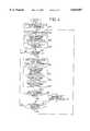
- FIG. 3is a block diagram schematically showing various functions of a control device used in the blood pressure monitor system of FIG. 1;
- FIG. 4is a flow chart representing a control routine executed by the control device in the blood pressure monitor system of FIG. 1;
- FIG. 5is a graph indicating an example of a first reference range which is obtained as a result of an operation of the monitor system according to the control routine of FIG. 4;
- FIG. 6is a graph indicating an example of a second reference range which is obtained as a result of an operation of the monitor system according to the control routine of FIG. 4.
- FIG. 1there is shown a blood pressure (BP) monitor system 8 constructed according to one embodiment of the present invention.
- the reference numeral 10denotes an inflatable cuff constituted by an elongate fabric bag and a rubber bag accommodated in the elongate fabric bag.
- the cuff 10is worn on a patient such that it is wound on an upper arm 12 of the patient, for example.
- a pressure sensor 14, a selector valve 16 and a first air pump 18are connected to the cuff 10 via a conduit piping 20.
- the selector valve 16is selectively placed in an inflation position, a slow-deflation position, and a rapid-deflation position.
- the selector valve 16In the inflation position, the selector valve 16 permits pressurized air to be supplied from the first air pump 18 to the cuff 10. In the slow-deflation position, the selector valve 16 permits the pressurized air to be slowly discharged from the cuff 10. In the rapid-deflation position, the selector valve 16 permits the pressurized air to be rapidly discharged from the cuff 10.
- the pressure sensor 14detects an air pressure in the cuff 10 and supplies an electric signal SP representative of the detected pressure to a static-pressure filter circuit 22 and a pulse-wave filter circuit 24.
- the static-pressure filter circuit 22has a low-pass filter and transmits a static component of the signal SP as a cuff-pressure signal SK to a control device 28 via a first analog to digital (A/D) converter 26.
- the pulse-wave filter circuit 24has a band-pass filter and transmits an oscillating component of the signal SP as a cuff pulse wave signal SM 1 to the control device 28 via a second analog to digital (A/D) converter 30.
- the cuff pulse wave signal SM 1is representative of a pulse wave, i.e., an oscillatory pressure wave which is produced from a brachial artery of the patient in synchronism with the heartbeat of the patient and transmitted to the cuff 10.
- the cuff 10, pressure sensor 14 and pulse-wave filter circuit 24cooperate with each other to function as a pulse wave sensor for obtaining the blood pressure of the patient.
- the control device 28is constituted by a so-called microcomputer which includes a central processing unit (CPU) 29, a read only memory (ROM) 31, a random access memory (RAM) 33 and an input and output (I/O) port not shown.
- the CPU 29performs signal processing operations according to control programs stored in the ROM 31 by utilizing a temporary data storage function of the RAM 33, and generates drive signals through the I/O port so as to control the selector valve 16 and first air pump 18.
- the present monitor system 8further includes a pulse wave probe 34.
- the probe 34is set on a wrist 42 located downstream of the arterial vessel of either one of the two upper arms 12, on which the cuff 10 is worn or is not worn.
- the probe 34includes a container-like housing 36 which is detachably set on a body surface 38 of the wrist 42 with a pair of bands 40, 40 fastened round the wrist 42, such that the open end of the housing 36 contacts the body surface 38 of the wrist 42.
- a pulse wave sensor 46is supported by the housing 36 via a flexible diaphragm 44, such that the pulse wave sensor 46 is displaceable relative to the housing 36 and is movable out of the housing 36 through its open end.
- the housing 36, diaphragm 44 and pulse wave sensor 46cooperate with each other to define a pressure chamber 48, to which pressurized air is supplied from a second air pump 50 via a pressure regulator valve 52.
- the pulse wave sensor 46is pressed against the body surface 38 with a pressing force P HD corresponding to an air pressure in the pressure chamber 48.
- the pulse wave sensor 46includes a plurality of semiconductor pressure-sensing elements (not shown) provided on one of opposite surfaces of a semiconductor substrate consisting of a single crystal of silicon, which one surface serves as a contact surface 54 of the pulse wave sensor 46.
- the pulse wave sensor 46is pressed at the contact surface 54 against the body surface 38 of the wrist 42, to detect the oscillatory pressure wave, i.e., pulse wave, which is produced by a radial artery 56 and transmitted to the body surface 38 and the contact surface 54.
- the pulse wave sensor 46generates a probe pulse wave signal SM2 representative of the detected pulse wave.
- the probe pulse wave signal SM2is supplied to the control device 28 via a third analog to digital (A/D) converter 58.
- the CPU 29 of the control device 28operates according to the control programs stored in the ROM 31, for applying drive signals to the second air pump 50 and the pressure regulator valve 52 so as to adjust the air pressure in the pressure chamber 48, in other words, to adjust the pressing force P HD of the pulse wave sensor 46 which acts on the body surface 38.
- the CPU 29determines an optimum pressing force P HDP of the pulse wave sensor 46, on the basis of the pulse waves obtained while the air pressure in the pressure chamber 48 is continuously changed.
- the pressure regulator valve 52is controlled so as to maintain the air pressure in the pressure chamber 48 at an optimum level corresponding to the determined optimum pressing force P HDP .
- FIG. 3illustrates various functions of the control device 28 of the present BP monitor system 8, which includes the above-indicated cuff 10 and pulse wave sensor 46.
- the BP monitor system 8further includes physical information obtaining means 78, moving average calculating means 80, reference range determining means 82 and abnormality determining means 84.
- the physical information obtaining means 78incorporates blood pressure (BP) obtaining means 72, relationship determining means 74 and blood pressure determining means 76.
- the blood pressure (BP) obtaining means 72is adapted to obtain a systolic blood pressure (SAP) and a diastolic blood pressure (DAP) of the patient according to a known oscillometric method (JIS T 1115).
- SAPsystolic blood pressure
- DAPdiastolic blood pressure
- the pressure in the cuff 10is first increased up to a predetermined target value (e.g., about 180 mmHg) higher by a suitable amount than an expected or estimated systolic blood pressure of the patient, the pressure in the cuff 10 is slowly lowered at a rate of about 3 mmHg/sec.
- the SAP and DAP valuesare determined on the basis of a change in the magnitudes of successive pulses of the pulse wave obtained by the pulse-wave filter circuit 24 while the pressure in the cuff 10 is slowly lowered.
- the pressure in the cuff 10is released.
- the pulse wave sensor 46is preferably worn on the wrist 42 of one of the arms 12 of the patient on which the cuff 10 is not wound, so that the pulse wave sensor 46 is pressed against the body surface 38 of the wrist 42 to detect the pulse wave generated from the radial artery of the wrist.
- the relationship determining means 74 of the physical information obtaining means 78is adapted to determine a relationship between a magnitude PM of the pulse wave detected by the pulse wave sensor 46 and the blood pressure determined by the BP obtaining means 72.
- the relationship between the pulse wave magnitude PM and the blood pressure(hereinafter referred to as "PW-BP relationship") is indicated in a graph of FIG. 2 by way of example, and represented by the following equation:
- MBPmonitored blood pressure
- Aa constant which represents a gradient
- the blood pressure determining means 76 of the physical information obtaining means 78is adapted to determine a monitored systolic blood pressure MBP SYS and a monitored diastolic blood pressure MBP DIA according to the determined PW-BP relationship, based on the magnitude PM of each pulse wave detected by the pulse wave sensor 46, i.e., on the basis of a maximum pulse wave magnitude (upper peak) P M2max and a minimum pulse wave magnitude (lower peak) P M2min .
- the determined blood pressure values MBP (MBP SYS and MBP DIA )are indicated on a display device 32, together with a pressure pulse wave indicative of the blood pressure of the patient, i.e., a waveform of the blood pressure.
- the physical information obtaining means 78is adapted to obtain the blood pressure (BP) waveform as an example of the physical information of the living subject.
- the moving average calculating means 80continuously calculates a moving average of a plurality of the physical information values which are successively obtained by the physical information obtaining means 78.
- the reference rangeis determined by the determining means 82.
- the abnormality determining means 84determines whether the physical information value currently obtained by the obtaining means 78 is outside the determined reference range. When the current physical information value is outside the reference range, the abnormality determining means 84 generates an abnormality signal so that the abnormality is visually indicated on a display device 32 or the like.
- the moving average calculating means 80is adapted to calculate a first moving average P AV1 and a second moving average P AV2 . Described more specifically, the calculating means 80 calculates the first average P AV1 of the physical information values obtained during a predetermined first time period, which is a relatively short time duration of about ten seconds to several tens of seconds. Similarly, the calculating means 80 calculates the second moving average P AV2 of the physical information values obtained during a predetermined second time period, which is sufficiently longer than the first time period for the first moving average P AV1 . The second time period is determined to be several tens of minutes, for instance.
- the reference range determining means 82determines, on the basis of the calculated first moving average P AV1 , a first reference range whose lower limit and upper limits are equal to (P AV1 - ⁇ ) and (P AV2 + ⁇ ), respectively. Similarly, the determining means 82 determines, on the basis of the calculated second moving average P AV2 , a second reference range whose lower and upper limits are equal to (P AV2 - ⁇ ) and (P AV2 + ⁇ ), respectively.
- the abnormality determining means 84generates a first abnormality signal when the physical information value currently obtained by the obtaining means 78 is outside the determined first reference range, and a second abnormality signal when the current physical information value is outside the determined second reference range. For example, the first abnormality signal is used to generate an alarm sound having a relatively low frequency while the second abnormality signal is used to generate an alarm sound having a relatively high frequency.
- control device 28There will be described the operation of the control device 28 referring to the flow chart of FIG. 4.
- a control routine illustrated in the flow chart of FIG. 4is initiated with step SA1 in which the air pressure in the pressure chamber 48 is slowly raised, and the CPU 29 determines the optimum air pressure in the pressure chamber 48, at which the amplitude of a pulse detected by the pulse wave sensor 46 is maximized.
- the air pressure in the chamber 48is held at the determined optimum level so that the pressing force of the pulse wave sensor 46 is maintained at the optimum value P HDP .
- Step SA1is followed by step SA2 in which the pressure in the cuff 10 is raised for effecting the blood pressure measurement in the following step SA3 corresponding to the BP obtaining means 72.
- step SA3the blood pressure of the patient is measured according to a predetermined blood pressure measuring algorithm. Described in detail, following the increase of the cuff pressure in step SA2, the selector valve 16 is placed in the inflation position and the first air pump 18 is actuated so as to increase the pressure in the cuff 10 up to a target value (e.g., 180 mmHg) higher by a suitable amount than the estimated systolic blood pressure of the patient.
- a target valuee.g. 180 mmHg
- the first air pump 18is turned off and the selector valve 16 is switched from the inflation position to the slow-deflation position so as to slowly decrease the pressure in the cuff 10 at a rate of 3 mmHg/sec.
- the systolic blood pressure (SAP), mean blood pressure (MAP) and diastolic blood pressure (DAP)are determined based on variation of the amplitudes of successive pulses of the cuff pulse wave signal SM1 obtained during the slow decreasing of the cuff pressure, according to a well-known oscillometric blood pressure determining algorithm, for example.
- the pulse rate (PR)is determined based on an interval between successive adjacent pulses of the cuff pulse wave signal SM1.
- the determined SAP, MAP, DAP and PR valuesare indicated on the display 32, and the selector valve 16 is switched from the slow-deflation position to the rapid-deflation position, whereby the pressure in the cuff 10 is rapidly lowered.
- step SA4corresponding to the PW-BP relationship determining means 74 so as to obtain a relationship between the magnitude (absolute value) of each pulse of the pulse wave detected by the pulse wave sensor 46 (i.e., magnitude of the probe pulse wave signal SM2) and the blood pressure values SAP, DAP measured by using the cuff 10 in step SA3.
- the PW-BP relationship determining means 74determines the relationship between the pulse wave magnitude PM and the monitored blood pressure MBP as indicated in the graph of FIG. 2, on the basis of the determined maximum and minimum pulse wave magnitudes P M2max , P M2min , and the systolic and diastolic blood pressure values SAP, DAP obtained by using the cuff 10 in step SA3.
- Step SA4is followed by step SA5 to determine whether one pulse of the probe pulse wave signal SM2 has been supplied from the pulse wave sensor 46. As long as a negative decision is obtained in step SAS, this step is repeatedly implemented. If an affirmative decision is obtained in step SA5, the control flow goes to steps SA6 and SA7 corresponding to the blood pressure determining means 76, so as to determine the maximum and minimum magnitudes (upper and lower peaks) of the pulse of the probe pulse wave signal SM2 received from the pulse wave sensor 46 which is pressed against the body surface 38 with the above-described optimum pressing force P HDP .
- a monitored systolic blood pressure MBP SYS and a monitored diastolic blood pressure MBP DIAare determined based on the maximum and minimum magnitudes P M2max and P M2min of the pulse of the probe pulse wave signal SM2, according to the PW-BP relationship (as shown in the graph of FIG. 2) which has been obtained in step SA4 as described above.
- the determined monitored systolic and diastolic blood pressure values MBP SYS and MBP DIAare indicated on the display device 32.
- the successively determined systolic blood pressure values MBP SYSare graphically represented as shown in FIGS. 5 and 6, so as to show a change of the MBP SYS values.
- step SA8corresponding to the moving average calculating means 80 to calculate the first moving average P AV1 and the second moving average P AV2 as described below. That is, the calculating means 80 calculates the first moving average P AV1 of the physical information values which are obtained during the first period of a few seconds to several tens of seconds and which include the latest BP value, e.g., the MBP SYS value, obtained in step SA7. Similarly, the calculating means 80 calculates the second moving average P AV2 of the physical information values obtained during the second period of several tens of minutes, which is sufficiently longer than the first period wherein the first moving average P AV1 is obtained.
- the calculating means 80calculates the first moving average P AV1 of the physical information values which are obtained during the first period of a few seconds to several tens of seconds and which include the latest BP value, e.g., the MBP SYS value, obtained in step SA7.
- the calculating means 80calculates the second moving average P AV2 of the physical information values
- Step SA8is followed by step SA9 corresponding to the reference range determining means 82, wherein the first and second reference ranges are respectively determined based on the first and second moving averages P AV1 , P AV2 determined in step SA8.
- the first reference rangeis determined for the purpose of quickly detecting the abnormality of the blood pressure due to a relatively abrupt change thereof.
- the first reference rangeis determined such that the range has a lower limit defined as (P AV1 - ⁇ ) and an upper limit defined as (P AV1 + ⁇ ), as shown in the graph of FIG. 5.
- the value ais equal to a few percent to about twenty percent of the first moving average P AV1 .
- the second reference rangeis determined for the purpose of detecting the abnormality of the blood pressure which arises from a relatively gradual change thereof. For instance, the second reference range is determined such that the lower limit is equal to (P AV2 - ⁇ ) and the upper limit is equal to (P AV2 + ⁇ ), as shown in the graph of FIG. 6. The value ⁇ is equal to a few percent to about twenty percent of the second moving average P AV2 .
- step SA10corresponding to the abnormality determining means 84 to determine whether the currently obtained systolic blood pressure MBP SYS falls within the first reference range and whether the systolic blood pressure MBPSYS falls within the second reference range. If a negative decision is obtained in step SA10, SA11 is implemented to generate an abnormality signal depending upon the determination in step SA10. Described more specifically, when the current MBP SYS deviates from the first reference range, the abnormality determining means 84 generates a first abnormality signal used to provide a visible or audible indication of a relatively rapid change in the blood pressure.
- the abnormality determining means 84when the MBP SYS deviates from the second reference range, the abnormality determining means 84 generates a second abnormality signal used to provide a visible or audible indication of a relatively gradual change in the blood pressure.
- the visible or audible indication according to the second abnormality signalis made different from that according to the first abnormality signal, so that the second abnormality can be easily distinguished from the first abnormality.
- Step SA11is followed by step SA12.
- This step SA 12is effected immediately following step SA10 if an affirmative decision is obtained in step SA10.
- Step SA12is provided to determine whether a predetermined time period has elapsed after the commencement of the blood pressure measurement by using the cuff 10 in step SA3. For example, the predetermined time period is several tens of minutes. If a negative decision is obtained in step SA12, the control flow goes back to step SA5 and the following steps for determining the monitored systolic and diastolic blood pressure MBP SYS and MBP DIA of the pulse wave signal SM2 and indicating the determined blood pressures MBP SYS and MBP DIA on the display device 32. On the other hand, if an affirmative decision is obtained in step SA12, the control flow goes back to step SA2 and the following steps so as to update the PW-BP relationship.
- the moving average calculating means 80 corresponding to step SA8continuously calculates the first moving average P AV1 of the systolic blood pressure values MBP SYS successively obtained by the physical information obtaining means 78 corresponding to steps SA2 through SA7.
- the reference range determining means 82 corresponding to step SA9determines the first reference range.
- the abnormality determining means 84 corresponding to step SA10determines whether the currently obtained value MBP SYS is outside the determined first reference range, and generates the first abnormality signal when the value MBP SYS is outside the first reference range.
- the first reference range used for determining the abnormality of the current value MBP SYSis determined based on the first moving average P AV1 of the successively obtained values MBP SYS . Accordingly, the present monitor system is capable of quickly detecting the change in the systolic blood pressure MBPSYS and accurately monitoring the blood pressure when the value MBP SYS abruptly changes even if the amount of change is relatively small.
- the calculating means 80 corresponding to step SA8calculates the first moving average P AV1 of the values MBP SYS obtained during the relatively short first time period, and the second moving average P AV2 of the values MBP SYS obtained during the second time period which is sufficiently longer than the first time period.
- the reference range determining means 82 corresponding to step SA9determines, on the basis of the calculated first moving average P AV1 , the first reference range defined by the upper limit of (P AV1 + ⁇ ) and the lower limit of (P AV2 - ⁇ ).
- the determining means 82determines, on the basis of the calculated second moving average P AV2 , the second reference range defined by the upper limit of (P AV2 + ⁇ ) and the lower limit of (P AV2 - ⁇ ).
- the abnormality determining means 84 corresponding to step SA10generates the first abnormality signal when the current value MBP SYS is outside the first reference range between (P AV1 - ⁇ ) and (P AV1 + ⁇ ), while the determining means 84 generates the second abnormality signal when the current value MBP SYS is outside the second reference range between (P AV2 - ⁇ ) and (P AV2 + ⁇ ).
- the present monitor systemis capable of detecting both of an abrupt and a gradual change in the systolic blood pressure MBP SYS .
- the systolic blood pressure MBP SYSis monitored as the physical information of the patient.
- the systolic blood pressure MBP SYSmay be replaced with the diastolic blood pressure MBP DIA or the mean blood pressure.
- the pulse rate, temperature, oxygen saturation, or fluctuation of these parametersmay be monitored by the present monitor system.
- the monitor system of the illustrated embodimentis arranged to determine whether the systolic blood pressure MBP SYS falls within the first reference range between (P AV1 - ⁇ ) and (P AV1 + ⁇ ) which is determined based on the first moving average P AV1 and whether the systolic blood pressure MBP SYS falls within the second reference range between (P AV2 - ⁇ ) and (P AV2 + ⁇ ) which is determined based on the second moving average P AV2 .
- the present monitor systemmay be modified to determine whether the systolic blood pressure MBP SYS is outside either one of the first and second reference ranges.
- the blood pressure obtaining means 72is adapted to determine the blood pressure according to the known oscillometric method, based on a change in the magnitude of the pulses of the pulse wave, which change is detected as the pressure in the cuff 10 is varied.
- the blood pressure obtaining means 72may be adapted to determine the blood pressure according to the known Korotkoff-sound method in which a microphone is used to detect presence and absence of Korotkoff sounds of an artery as the pressure in the cuff 10 is changed.
Landscapes
- Health & Medical Sciences (AREA)
- Life Sciences & Earth Sciences (AREA)
- Vascular Medicine (AREA)
- Cardiology (AREA)
- Biomedical Technology (AREA)
- Heart & Thoracic Surgery (AREA)
- Physiology (AREA)
- Biophysics (AREA)
- Pathology (AREA)
- Engineering & Computer Science (AREA)
- Ophthalmology & Optometry (AREA)
- Physics & Mathematics (AREA)
- Medical Informatics (AREA)
- Molecular Biology (AREA)
- Surgery (AREA)
- Animal Behavior & Ethology (AREA)
- General Health & Medical Sciences (AREA)
- Public Health (AREA)
- Veterinary Medicine (AREA)
- Measuring Pulse, Heart Rate, Blood Pressure Or Blood Flow (AREA)
Abstract
Description
MBP=A·PM+B,
Claims (4)
Priority Applications (2)
| Application Number | Priority Date | Filing Date | Title |
|---|---|---|---|
| US08/716,604US5836887A (en) | 1996-09-19 | 1996-09-19 | Physical information monitor system having means for determining reference range for abnormality determination, based on moving average of previously obtained values |
| EP96115384AEP0832601B1 (en) | 1996-09-19 | 1996-09-25 | Physical information monitor system having means for determining reference range for abnormality determination, based on moving average of previously obtained values |
Applications Claiming Priority (2)
| Application Number | Priority Date | Filing Date | Title |
|---|---|---|---|
| US08/716,604US5836887A (en) | 1996-09-19 | 1996-09-19 | Physical information monitor system having means for determining reference range for abnormality determination, based on moving average of previously obtained values |
| EP96115384AEP0832601B1 (en) | 1996-09-19 | 1996-09-25 | Physical information monitor system having means for determining reference range for abnormality determination, based on moving average of previously obtained values |
Publications (1)
| Publication Number | Publication Date |
|---|---|
| US5836887Atrue US5836887A (en) | 1998-11-17 |
Family
ID=26142195
Family Applications (1)
| Application Number | Title | Priority Date | Filing Date |
|---|---|---|---|
| US08/716,604Expired - Fee RelatedUS5836887A (en) | 1996-09-19 | 1996-09-19 | Physical information monitor system having means for determining reference range for abnormality determination, based on moving average of previously obtained values |
Country Status (2)
| Country | Link |
|---|---|
| US (1) | US5836887A (en) |
| EP (1) | EP0832601B1 (en) |
Cited By (89)
| Publication number | Priority date | Publication date | Assignee | Title |
|---|---|---|---|---|
| US6152880A (en)* | 1998-12-18 | 2000-11-28 | Matsushita Electric Works, Ltd. | Self-diagnostic blood pressure measuring apparatus |
| US6241680B1 (en)* | 1998-10-30 | 2001-06-05 | Colin Corporation | Blood-pressure monitoring apparatus |
| US6332867B1 (en) | 1999-06-09 | 2001-12-25 | Vsm Technology Inc. | Method and apparatus for measuring values of physiological parameters |
| US6482163B2 (en)* | 2000-07-26 | 2002-11-19 | Colin Corporation | Postoperative-condition evaluating apparatus |
| US20020177781A1 (en)* | 2001-04-19 | 2002-11-28 | Seiko Epson Corporation | Central blood pressure waveform estimation device and peripheral blood pressure waveform detection device |
| US6640126B2 (en) | 2001-02-26 | 2003-10-28 | Toshiba America Mri, Inc. | Acoustic gating monitor for magnetic resonance imaging system |
| EP1468643A1 (en)* | 2003-04-15 | 2004-10-20 | Omron Healthcare Co., Ltd. | Pulse wave measuring apparatus with optimum pressurization force of pressure sensor |
| US20050119578A1 (en)* | 2002-03-28 | 2005-06-02 | Takeshi Kubo | Electronic hemomanometer and blood pressure measuring method of electronic hemomanometer |
| US20050171444A1 (en)* | 2003-12-08 | 2005-08-04 | Nihon Kohden Corporation | Vital sign telemeter |
| US6931327B2 (en) | 2003-08-01 | 2005-08-16 | Dexcom, Inc. | System and methods for processing analyte sensor data |
| US20070038129A1 (en)* | 2005-08-12 | 2007-02-15 | Omron Healthcare Co., Ltd. | Electronic blood pressure monitor calculating average value of blood pressure |
| US20070049834A1 (en)* | 2005-08-31 | 2007-03-01 | Shenzhen Mindray Bio-Medical Electronics Co., Ltd | Method and apparatus for calculating blood pressure with signal transformation |
| US20080045846A1 (en)* | 2006-08-16 | 2008-02-21 | Friedman Bruce A | Method and system of determining nibp target inflation pressure using an sp02 plethysmograph signal |
| US20080132769A1 (en)* | 2004-10-05 | 2008-06-05 | Henderson Leslie G | Non-invasively monitoring blood parameters |
| US7613491B2 (en) | 2002-05-22 | 2009-11-03 | Dexcom, Inc. | Silicone based membranes for use in implantable glucose sensors |
| US20100081904A1 (en)* | 2008-09-30 | 2010-04-01 | Nellcor Puritan Bennett Llc | Device And Method For Securing A Medical Sensor to An Infant's Head |
| US7698909B2 (en) | 2002-10-01 | 2010-04-20 | Nellcor Puritan Bennett Llc | Headband with tension indicator |
| US20100121226A1 (en)* | 2007-04-19 | 2010-05-13 | Koninklijke Philips Electronics N.V. | Fall detection system |
| US7774145B2 (en) | 2003-08-01 | 2010-08-10 | Dexcom, Inc. | Transcutaneous analyte sensor |
| US7783333B2 (en) | 2004-07-13 | 2010-08-24 | Dexcom, Inc. | Transcutaneous medical device with variable stiffness |
| US20100249616A1 (en)* | 2009-03-26 | 2010-09-30 | The General Electric Company | Nibp target inflation pressure automation using derived spo2 signals |
| US7809420B2 (en) | 2003-06-25 | 2010-10-05 | Nellcor Puritan Bennett Llc | Hat-based oximeter sensor |
| US7810359B2 (en) | 2002-10-01 | 2010-10-12 | Nellcor Puritan Bennett Llc | Headband with tension indicator |
| US7857760B2 (en) | 2004-07-13 | 2010-12-28 | Dexcom, Inc. | Analyte sensor |
| US7860544B2 (en) | 1998-04-30 | 2010-12-28 | Abbott Diabetes Care Inc. | Analyte monitoring device and methods of use |
| US7905833B2 (en) | 2004-07-13 | 2011-03-15 | Dexcom, Inc. | Transcutaneous analyte sensor |
| US7914450B2 (en) | 2003-08-01 | 2011-03-29 | Dexcom, Inc. | System and methods for processing analyte sensor data |
| US7920907B2 (en) | 2006-06-07 | 2011-04-05 | Abbott Diabetes Care Inc. | Analyte monitoring system and method |
| US7920906B2 (en) | 2005-03-10 | 2011-04-05 | Dexcom, Inc. | System and methods for processing analyte sensor data for sensor calibration |
| US7927274B2 (en) | 2003-11-19 | 2011-04-19 | Dexcom, Inc. | Integrated receiver for continuous analyte sensor |
| US7935057B2 (en) | 2003-08-22 | 2011-05-03 | Dexcom, Inc. | Systems and methods for replacing signal artifacts in a glucose sensor data stream |
| US7976492B2 (en) | 2004-02-26 | 2011-07-12 | Dexcom, Inc. | Integrated delivery device for continuous glucose sensor |
| US7976778B2 (en) | 2001-04-02 | 2011-07-12 | Abbott Diabetes Care Inc. | Blood glucose tracking apparatus |
| US8005524B2 (en) | 2003-12-09 | 2011-08-23 | Dexcom, Inc. | Signal processing for continuous analyte sensor |
| US8160669B2 (en) | 2003-08-01 | 2012-04-17 | Dexcom, Inc. | Transcutaneous analyte sensor |
| US8160671B2 (en) | 2003-12-05 | 2012-04-17 | Dexcom, Inc. | Calibration techniques for a continuous analyte sensor |
| US20120095722A1 (en)* | 2009-07-10 | 2012-04-19 | Koninklijke Philips Electronics N.V. | Fall prevention |
| US20120095304A1 (en)* | 2005-12-15 | 2012-04-19 | Cardiopulmonary Corporation | System and Method for Determining a Patient Clinical Status |
| US8229535B2 (en) | 2008-02-21 | 2012-07-24 | Dexcom, Inc. | Systems and methods for blood glucose monitoring and alert delivery |
| US8233959B2 (en) | 2003-08-22 | 2012-07-31 | Dexcom, Inc. | Systems and methods for processing analyte sensor data |
| US8257274B2 (en) | 2008-09-25 | 2012-09-04 | Nellcor Puritan Bennett Llc | Medical sensor and technique for using the same |
| US8260393B2 (en) | 2003-07-25 | 2012-09-04 | Dexcom, Inc. | Systems and methods for replacing signal data artifacts in a glucose sensor data stream |
| US8275437B2 (en) | 2003-08-01 | 2012-09-25 | Dexcom, Inc. | Transcutaneous analyte sensor |
| US8287454B2 (en) | 1998-04-30 | 2012-10-16 | Abbott Diabetes Care Inc. | Analyte monitoring device and methods of use |
| US8287453B2 (en) | 2003-12-05 | 2012-10-16 | Dexcom, Inc. | Analyte sensor |
| US8290559B2 (en) | 2007-12-17 | 2012-10-16 | Dexcom, Inc. | Systems and methods for processing sensor data |
| US8346337B2 (en) | 1998-04-30 | 2013-01-01 | Abbott Diabetes Care Inc. | Analyte monitoring device and methods of use |
| US8364229B2 (en) | 2003-07-25 | 2013-01-29 | Dexcom, Inc. | Analyte sensors having a signal-to-noise ratio substantially unaffected by non-constant noise |
| US8364220B2 (en) | 2008-09-25 | 2013-01-29 | Covidien Lp | Medical sensor and technique for using the same |
| US8369919B2 (en) | 2003-08-01 | 2013-02-05 | Dexcom, Inc. | Systems and methods for processing sensor data |
| US8412297B2 (en) | 2003-10-01 | 2013-04-02 | Covidien Lp | Forehead sensor placement |
| US8417312B2 (en) | 2007-10-25 | 2013-04-09 | Dexcom, Inc. | Systems and methods for processing sensor data |
| US8423113B2 (en) | 2003-07-25 | 2013-04-16 | Dexcom, Inc. | Systems and methods for processing sensor data |
| US8463350B2 (en) | 2004-07-13 | 2013-06-11 | Dexcom, Inc. | Transcutaneous analyte sensor |
| US8465425B2 (en) | 1998-04-30 | 2013-06-18 | Abbott Diabetes Care Inc. | Analyte monitoring device and methods of use |
| US20130211269A1 (en)* | 2009-06-23 | 2013-08-15 | Infarct Reduction Technologies Inc. | Multi-mode inflatable limb occlusion device |
| US8515515B2 (en) | 2009-03-25 | 2013-08-20 | Covidien Lp | Medical sensor with compressible light barrier and technique for using the same |
| US8548553B2 (en) | 2003-08-01 | 2013-10-01 | Dexcom, Inc. | System and methods for processing analyte sensor data |
| US8562558B2 (en) | 2007-06-08 | 2013-10-22 | Dexcom, Inc. | Integrated medicament delivery device for use with continuous analyte sensor |
| US8612159B2 (en) | 1998-04-30 | 2013-12-17 | Abbott Diabetes Care Inc. | Analyte monitoring device and methods of use |
| US8622905B2 (en) | 2003-08-01 | 2014-01-07 | Dexcom, Inc. | System and methods for processing analyte sensor data |
| US8652043B2 (en) | 2001-01-02 | 2014-02-18 | Abbott Diabetes Care Inc. | Analyte monitoring device and methods of use |
| US8688188B2 (en) | 1998-04-30 | 2014-04-01 | Abbott Diabetes Care Inc. | Analyte monitoring device and methods of use |
| US8777853B2 (en) | 2003-08-22 | 2014-07-15 | Dexcom, Inc. | Systems and methods for replacing signal artifacts in a glucose sensor data stream |
| US8781548B2 (en) | 2009-03-31 | 2014-07-15 | Covidien Lp | Medical sensor with flexible components and technique for using the same |
| US8886273B2 (en) | 2003-08-01 | 2014-11-11 | Dexcom, Inc. | Analyte sensor |
| US8974386B2 (en) | 1998-04-30 | 2015-03-10 | Abbott Diabetes Care Inc. | Analyte monitoring device and methods of use |
| US9066695B2 (en) | 1998-04-30 | 2015-06-30 | Abbott Diabetes Care Inc. | Analyte monitoring device and methods of use |
| US9135402B2 (en) | 2007-12-17 | 2015-09-15 | Dexcom, Inc. | Systems and methods for processing sensor data |
| US9282925B2 (en) | 2002-02-12 | 2016-03-15 | Dexcom, Inc. | Systems and methods for replacing signal artifacts in a glucose sensor data stream |
| US9301700B2 (en) | 2012-09-27 | 2016-04-05 | Welch Allyn, Inc. | Configurable vital signs system |
| US9446194B2 (en) | 2009-03-27 | 2016-09-20 | Dexcom, Inc. | Methods and systems for promoting glucose management |
| US9451908B2 (en) | 2006-10-04 | 2016-09-27 | Dexcom, Inc. | Analyte sensor |
| CN106073750A (en)* | 2016-08-29 | 2016-11-09 | 廖晓莉 | Ventricle blood supply abnormal detector and the indirect acquiring and processing method of heart pulse wave data |
| US9763609B2 (en) | 2003-07-25 | 2017-09-19 | Dexcom, Inc. | Analyte sensors having a signal-to-noise ratio substantially unaffected by non-constant noise |
| US20190340908A1 (en)* | 2017-04-03 | 2019-11-07 | Oneevent Technologies, Inc. | System and method for monitoring a building |
| US10653835B2 (en) | 2007-10-09 | 2020-05-19 | Dexcom, Inc. | Integrated insulin delivery system with continuous glucose sensor |
| US10791928B2 (en) | 2007-05-18 | 2020-10-06 | Dexcom, Inc. | Analyte sensors having a signal-to-noise ratio substantially unaffected by non-constant noise |
| US10813577B2 (en) | 2005-06-21 | 2020-10-27 | Dexcom, Inc. | Analyte sensor |
| US10966609B2 (en) | 2004-02-26 | 2021-04-06 | Dexcom, Inc. | Integrated medicament delivery device for use with continuous analyte sensor |
| US10980461B2 (en) | 2008-11-07 | 2021-04-20 | Dexcom, Inc. | Advanced analyte sensor calibration and error detection |
| US11000215B1 (en) | 2003-12-05 | 2021-05-11 | Dexcom, Inc. | Analyte sensor |
| US11071467B2 (en) | 2013-08-08 | 2021-07-27 | Welch Allyn, Inc. | Hybrid patient monitoring system |
| US11331022B2 (en) | 2017-10-24 | 2022-05-17 | Dexcom, Inc. | Pre-connected analyte sensors |
| US11350862B2 (en) | 2017-10-24 | 2022-06-07 | Dexcom, Inc. | Pre-connected analyte sensors |
| US11382539B2 (en) | 2006-10-04 | 2022-07-12 | Dexcom, Inc. | Analyte sensor |
| US11399745B2 (en) | 2006-10-04 | 2022-08-02 | Dexcom, Inc. | Dual electrode system for a continuous analyte sensor |
| US11559260B2 (en) | 2003-08-22 | 2023-01-24 | Dexcom, Inc. | Systems and methods for processing analyte sensor data |
| US11633133B2 (en) | 2003-12-05 | 2023-04-25 | Dexcom, Inc. | Dual electrode system for a continuous analyte sensor |
Citations (14)
| Publication number | Priority date | Publication date | Assignee | Title |
|---|---|---|---|---|
| US4197854A (en)* | 1974-07-19 | 1980-04-15 | Medicor Muvek | Process and apparatus for patient danger recognition and forecasting of a danger condition, especially in case of intensive medical care |
| US4245648A (en)* | 1978-09-20 | 1981-01-20 | Trimmer Gordon A | Method and apparatus for measuring blood pressure and pulse rate |
| US4479494A (en)* | 1982-01-05 | 1984-10-30 | Western Clinical Engineering Ltd. | Adaptive pneumatic tourniquet |
| US4889131A (en)* | 1987-12-03 | 1989-12-26 | American Health Products, Inc. | Portable belt monitor of physiological functions and sensors therefor |
| US4944305A (en)* | 1989-04-20 | 1990-07-31 | Colin Electronics Co., Ltd. | Blood pressure monitoring apparatus |
| US4951679A (en)* | 1988-01-29 | 1990-08-28 | Colin Electronics Co., Ltd. | Pulse wave detecting apparatus having placement-condition detecting means |
| US5226416A (en)* | 1988-06-16 | 1993-07-13 | Pneu Pac Limited | Monitoring and alarm apparatus |
| US5253648A (en)* | 1991-10-11 | 1993-10-19 | Spacelabs Medical, Inc. | Method and apparatus for excluding artifacts from automatic blood pressure measurements |
| US5279303A (en)* | 1991-06-14 | 1994-01-18 | Colin Electronics Co., Ltd. | Blood pressure monitor system |
| US5319355A (en)* | 1991-03-06 | 1994-06-07 | Russek Linda G | Alarm for patient monitor and life support equipment system |
| US5343868A (en)* | 1992-04-02 | 1994-09-06 | Hewlett-Packard Company | Method and apparatus for detecting artifacts in a blood pressure measuring system |
| US5355893A (en)* | 1992-04-06 | 1994-10-18 | Mick Peter R | Vital signs monitor |
| GB2281780A (en)* | 1993-09-13 | 1995-03-15 | Hewlett Packard Co | Patient alarm detection using trend vector analysis |
| US5464012A (en)* | 1993-09-13 | 1995-11-07 | Hewlett-Packard Company | Patient alarm detection using target mode |
- 1996
- 1996-09-19USUS08/716,604patent/US5836887A/ennot_activeExpired - Fee Related
- 1996-09-25EPEP96115384Apatent/EP0832601B1/ennot_activeExpired - Lifetime
Patent Citations (14)
| Publication number | Priority date | Publication date | Assignee | Title |
|---|---|---|---|---|
| US4197854A (en)* | 1974-07-19 | 1980-04-15 | Medicor Muvek | Process and apparatus for patient danger recognition and forecasting of a danger condition, especially in case of intensive medical care |
| US4245648A (en)* | 1978-09-20 | 1981-01-20 | Trimmer Gordon A | Method and apparatus for measuring blood pressure and pulse rate |
| US4479494A (en)* | 1982-01-05 | 1984-10-30 | Western Clinical Engineering Ltd. | Adaptive pneumatic tourniquet |
| US4889131A (en)* | 1987-12-03 | 1989-12-26 | American Health Products, Inc. | Portable belt monitor of physiological functions and sensors therefor |
| US4951679A (en)* | 1988-01-29 | 1990-08-28 | Colin Electronics Co., Ltd. | Pulse wave detecting apparatus having placement-condition detecting means |
| US5226416A (en)* | 1988-06-16 | 1993-07-13 | Pneu Pac Limited | Monitoring and alarm apparatus |
| US4944305A (en)* | 1989-04-20 | 1990-07-31 | Colin Electronics Co., Ltd. | Blood pressure monitoring apparatus |
| US5319355A (en)* | 1991-03-06 | 1994-06-07 | Russek Linda G | Alarm for patient monitor and life support equipment system |
| US5279303A (en)* | 1991-06-14 | 1994-01-18 | Colin Electronics Co., Ltd. | Blood pressure monitor system |
| US5253648A (en)* | 1991-10-11 | 1993-10-19 | Spacelabs Medical, Inc. | Method and apparatus for excluding artifacts from automatic blood pressure measurements |
| US5343868A (en)* | 1992-04-02 | 1994-09-06 | Hewlett-Packard Company | Method and apparatus for detecting artifacts in a blood pressure measuring system |
| US5355893A (en)* | 1992-04-06 | 1994-10-18 | Mick Peter R | Vital signs monitor |
| GB2281780A (en)* | 1993-09-13 | 1995-03-15 | Hewlett Packard Co | Patient alarm detection using trend vector analysis |
| US5464012A (en)* | 1993-09-13 | 1995-11-07 | Hewlett-Packard Company | Patient alarm detection using target mode |
Cited By (385)
| Publication number | Priority date | Publication date | Assignee | Title |
|---|---|---|---|---|
| US8622906B2 (en) | 1998-04-30 | 2014-01-07 | Abbott Diabetes Care Inc. | Analyte monitoring device and methods of use |
| US9066697B2 (en) | 1998-04-30 | 2015-06-30 | Abbott Diabetes Care Inc. | Analyte monitoring device and methods of use |
| US9326714B2 (en) | 1998-04-30 | 2016-05-03 | Abbott Diabetes Care Inc. | Analyte monitoring device and methods of use |
| US9072477B2 (en) | 1998-04-30 | 2015-07-07 | Abbott Diabetes Care Inc. | Analyte monitoring device and methods of use |
| US9066695B2 (en) | 1998-04-30 | 2015-06-30 | Abbott Diabetes Care Inc. | Analyte monitoring device and methods of use |
| US8175673B2 (en) | 1998-04-30 | 2012-05-08 | Abbott Diabetes Care Inc. | Analyte monitoring device and methods of use |
| US8162829B2 (en) | 1998-04-30 | 2012-04-24 | Abbott Diabetes Care Inc. | Analyte monitoring device and methods of use |
| US8177716B2 (en) | 1998-04-30 | 2012-05-15 | Abbott Diabetes Care Inc. | Analyte monitoring device and methods of use |
| US9066694B2 (en) | 1998-04-30 | 2015-06-30 | Abbott Diabetes Care Inc. | Analyte monitoring device and methods of use |
| US8612159B2 (en) | 1998-04-30 | 2013-12-17 | Abbott Diabetes Care Inc. | Analyte monitoring device and methods of use |
| US9042953B2 (en) | 1998-04-30 | 2015-05-26 | Abbott Diabetes Care Inc. | Analyte monitoring device and methods of use |
| US8224413B2 (en) | 1998-04-30 | 2012-07-17 | Abbott Diabetes Care Inc. | Analyte monitoring device and methods of use |
| US8226555B2 (en) | 1998-04-30 | 2012-07-24 | Abbott Diabetes Care Inc. | Analyte monitoring device and methods of use |
| US8226558B2 (en) | 1998-04-30 | 2012-07-24 | Abbott Diabetes Care Inc. | Analyte monitoring device and methods of use |
| US8226557B2 (en) | 1998-04-30 | 2012-07-24 | Abbott Diabetes Care Inc. | Analyte monitoring device and methods of use |
| US9011331B2 (en) | 1998-04-30 | 2015-04-21 | Abbott Diabetes Care Inc. | Analyte monitoring device and methods of use |
| US9014773B2 (en) | 1998-04-30 | 2015-04-21 | Abbott Diabetes Care Inc. | Analyte monitoring device and methods of use |
| US8974386B2 (en) | 1998-04-30 | 2015-03-10 | Abbott Diabetes Care Inc. | Analyte monitoring device and methods of use |
| US8880137B2 (en) | 1998-04-30 | 2014-11-04 | Abbott Diabetes Care Inc. | Analyte monitoring device and methods of use |
| US8840553B2 (en) | 1998-04-30 | 2014-09-23 | Abbott Diabetes Care Inc. | Analyte monitoring device and methods of use |
| US8774887B2 (en) | 1998-04-30 | 2014-07-08 | Abbott Diabetes Care Inc. | Analyte monitoring device and methods of use |
| US8744545B2 (en) | 1998-04-30 | 2014-06-03 | Abbott Diabetes Care Inc. | Analyte monitoring device and methods of use |
| US8734348B2 (en) | 1998-04-30 | 2014-05-27 | Abbott Diabetes Care Inc. | Analyte monitoring device and methods of use |
| US8738109B2 (en) | 1998-04-30 | 2014-05-27 | Abbott Diabetes Care Inc. | Analyte monitoring device and methods of use |
| US8734346B2 (en) | 1998-04-30 | 2014-05-27 | Abbott Diabetes Care Inc. | Analyte monitoring device and methods of use |
| US8688188B2 (en) | 1998-04-30 | 2014-04-01 | Abbott Diabetes Care Inc. | Analyte monitoring device and methods of use |
| US8672844B2 (en) | 1998-04-30 | 2014-03-18 | Abbott Diabetes Care Inc. | Analyte monitoring device and methods of use |
| US8231532B2 (en) | 1998-04-30 | 2012-07-31 | Abbott Diabetes Care Inc. | Analyte monitoring device and methods of use |
| US8670815B2 (en) | 1998-04-30 | 2014-03-11 | Abbott Diabetes Care Inc. | Analyte monitoring device and methods of use |
| US8666469B2 (en) | 1998-04-30 | 2014-03-04 | Abbott Diabetes Care Inc. | Analyte monitoring device and methods of use |
| US8660627B2 (en) | 1998-04-30 | 2014-02-25 | Abbott Diabetes Care Inc. | Analyte monitoring device and methods of use |
| US8235896B2 (en) | 1998-04-30 | 2012-08-07 | Abbott Diabetes Care Inc. | Analyte monitoring device and methods of use |
| US8649841B2 (en) | 1998-04-30 | 2014-02-11 | Abbott Diabetes Care Inc. | Analyte monitoring device and methods of use |
| US8641619B2 (en) | 1998-04-30 | 2014-02-04 | Abbott Diabetes Care Inc. | Analyte monitoring device and methods of use |
| US8255031B2 (en) | 1998-04-30 | 2012-08-28 | Abbott Diabetes Care Inc. | Analyte monitoring device and methods of use |
| US7860544B2 (en) | 1998-04-30 | 2010-12-28 | Abbott Diabetes Care Inc. | Analyte monitoring device and methods of use |
| US10478108B2 (en) | 1998-04-30 | 2019-11-19 | Abbott Diabetes Care Inc. | Analyte monitoring device and methods of use |
| US8597189B2 (en) | 1998-04-30 | 2013-12-03 | Abbott Diabetes Care Inc. | Analyte monitoring device and methods of use |
| US8480580B2 (en) | 1998-04-30 | 2013-07-09 | Abbott Diabetes Care Inc. | Analyte monitoring device and methods of use |
| US8473021B2 (en) | 1998-04-30 | 2013-06-25 | Abbott Diabetes Care Inc. | Analyte monitoring device and methods of use |
| US8617071B2 (en) | 1998-04-30 | 2013-12-31 | Abbott Diabetes Care Inc. | Analyte monitoring device and methods of use |
| US7869853B1 (en) | 1998-04-30 | 2011-01-11 | Abbott Diabetes Care Inc. | Analyte monitoring device and methods of use |
| US8465425B2 (en) | 1998-04-30 | 2013-06-18 | Abbott Diabetes Care Inc. | Analyte monitoring device and methods of use |
| US8409131B2 (en) | 1998-04-30 | 2013-04-02 | Abbott Diabetes Care Inc. | Analyte monitoring device and methods of use |
| US7885699B2 (en) | 1998-04-30 | 2011-02-08 | Abbott Diabetes Care Inc. | Analyte monitoring device and methods of use |
| US8391945B2 (en) | 1998-04-30 | 2013-03-05 | Abbott Diabetes Care Inc. | Analyte monitoring device and methods of use |
| US8380273B2 (en) | 1998-04-30 | 2013-02-19 | Abbott Diabetes Care Inc. | Analyte monitoring device and methods of use |
| US8372005B2 (en) | 1998-04-30 | 2013-02-12 | Abbott Diabetes Care Inc. | Analyte monitoring device and methods of use |
| US8366614B2 (en) | 1998-04-30 | 2013-02-05 | Abbott Diabetes Care Inc. | Analyte monitoring device and methods of use |
| US8357091B2 (en) | 1998-04-30 | 2013-01-22 | Abbott Diabetes Care Inc. | Analyte monitoring device and methods of use |
| US8353829B2 (en) | 1998-04-30 | 2013-01-15 | Abbott Diabetes Care Inc. | Analyte monitoring device and methods of use |
| US8346336B2 (en) | 1998-04-30 | 2013-01-01 | Abbott Diabetes Care Inc. | Analyte monitoring device and methods of use |
| US8346337B2 (en) | 1998-04-30 | 2013-01-01 | Abbott Diabetes Care Inc. | Analyte monitoring device and methods of use |
| US8306598B2 (en) | 1998-04-30 | 2012-11-06 | Abbott Diabetes Care Inc. | Analyte monitoring device and methods of use |
| US8287454B2 (en) | 1998-04-30 | 2012-10-16 | Abbott Diabetes Care Inc. | Analyte monitoring device and methods of use |
| US8273022B2 (en) | 1998-04-30 | 2012-09-25 | Abbott Diabetes Care Inc. | Analyte monitoring device and methods of use |
| US8275439B2 (en) | 1998-04-30 | 2012-09-25 | Abbott Diabetes Care Inc. | Analyte monitoring device and methods of use |
| US8265726B2 (en) | 1998-04-30 | 2012-09-11 | Abbott Diabetes Care Inc. | Analyte monitoring device and methods of use |
| US8260392B2 (en) | 1998-04-30 | 2012-09-04 | Abbott Diabetes Care Inc. | Analyte monitoring device and methods of use |
| US6241680B1 (en)* | 1998-10-30 | 2001-06-05 | Colin Corporation | Blood-pressure monitoring apparatus |
| US6152880A (en)* | 1998-12-18 | 2000-11-28 | Matsushita Electric Works, Ltd. | Self-diagnostic blood pressure measuring apparatus |
| US6332867B1 (en) | 1999-06-09 | 2001-12-25 | Vsm Technology Inc. | Method and apparatus for measuring values of physiological parameters |
| US6602199B2 (en) | 1999-06-09 | 2003-08-05 | Vsm Technology Inc. | Method and apparatus for measuring values of physiological parameters |
| US6482163B2 (en)* | 2000-07-26 | 2002-11-19 | Colin Corporation | Postoperative-condition evaluating apparatus |
| US8652043B2 (en) | 2001-01-02 | 2014-02-18 | Abbott Diabetes Care Inc. | Analyte monitoring device and methods of use |
| US8668645B2 (en) | 2001-01-02 | 2014-03-11 | Abbott Diabetes Care Inc. | Analyte monitoring device and methods of use |
| US9011332B2 (en) | 2001-01-02 | 2015-04-21 | Abbott Diabetes Care Inc. | Analyte monitoring device and methods of use |
| US9498159B2 (en) | 2001-01-02 | 2016-11-22 | Abbott Diabetes Care Inc. | Analyte monitoring device and methods of use |
| US9610034B2 (en) | 2001-01-02 | 2017-04-04 | Abbott Diabetes Care Inc. | Analyte monitoring device and methods of use |
| US6640126B2 (en) | 2001-02-26 | 2003-10-28 | Toshiba America Mri, Inc. | Acoustic gating monitor for magnetic resonance imaging system |
| US8236242B2 (en) | 2001-04-02 | 2012-08-07 | Abbott Diabetes Care Inc. | Blood glucose tracking apparatus and methods |
| US7976778B2 (en) | 2001-04-02 | 2011-07-12 | Abbott Diabetes Care Inc. | Blood glucose tracking apparatus |
| US8765059B2 (en) | 2001-04-02 | 2014-07-01 | Abbott Diabetes Care Inc. | Blood glucose tracking apparatus |
| US8268243B2 (en) | 2001-04-02 | 2012-09-18 | Abbott Diabetes Care Inc. | Blood glucose tracking apparatus and methods |
| US9477811B2 (en) | 2001-04-02 | 2016-10-25 | Abbott Diabetes Care Inc. | Blood glucose tracking apparatus and methods |
| US20020177781A1 (en)* | 2001-04-19 | 2002-11-28 | Seiko Epson Corporation | Central blood pressure waveform estimation device and peripheral blood pressure waveform detection device |
| US6740045B2 (en)* | 2001-04-19 | 2004-05-25 | Seiko Epson Corporation | Central blood pressure waveform estimation device and peripheral blood pressure waveform detection device |
| US9282925B2 (en) | 2002-02-12 | 2016-03-15 | Dexcom, Inc. | Systems and methods for replacing signal artifacts in a glucose sensor data stream |
| US7029448B2 (en)* | 2002-03-28 | 2006-04-18 | Omron Corporation | Electronic hemomanometer and blood pressure measuring method of electronic hemomanometer |
| US20050119578A1 (en)* | 2002-03-28 | 2005-06-02 | Takeshi Kubo | Electronic hemomanometer and blood pressure measuring method of electronic hemomanometer |
| US10052051B2 (en) | 2002-05-22 | 2018-08-21 | Dexcom, Inc. | Silicone based membranes for use in implantable glucose sensors |
| US8064977B2 (en) | 2002-05-22 | 2011-11-22 | Dexcom, Inc. | Silicone based membranes for use in implantable glucose sensors |
| US8543184B2 (en) | 2002-05-22 | 2013-09-24 | Dexcom, Inc. | Silicone based membranes for use in implantable glucose sensors |
| US9549693B2 (en) | 2002-05-22 | 2017-01-24 | Dexcom, Inc. | Silicone based membranes for use in implantable glucose sensors |
| US11020026B2 (en) | 2002-05-22 | 2021-06-01 | Dexcom, Inc. | Silicone based membranes for use in implantable glucose sensors |
| US7613491B2 (en) | 2002-05-22 | 2009-11-03 | Dexcom, Inc. | Silicone based membranes for use in implantable glucose sensors |
| US7810359B2 (en) | 2002-10-01 | 2010-10-12 | Nellcor Puritan Bennett Llc | Headband with tension indicator |
| US7698909B2 (en) | 2002-10-01 | 2010-04-20 | Nellcor Puritan Bennett Llc | Headband with tension indicator |
| US7822453B2 (en) | 2002-10-01 | 2010-10-26 | Nellcor Puritan Bennett Llc | Forehead sensor placement |
| US8452367B2 (en) | 2002-10-01 | 2013-05-28 | Covidien Lp | Forehead sensor placement |
| US7899509B2 (en) | 2002-10-01 | 2011-03-01 | Nellcor Puritan Bennett Llc | Forehead sensor placement |
| US7229414B2 (en) | 2003-04-15 | 2007-06-12 | Omron Healthcare Co., Ltd. | Pulse wave measuring apparatus that can obtain optimum pressurization force of pressure sensor |
| CN1311784C (en)* | 2003-04-15 | 2007-04-25 | 欧姆龙健康医疗事业株式会社 | Pulse wave measuring device capable of acquirinb optimal pressing force of pressure sensor |
| US20040210142A1 (en)* | 2003-04-15 | 2004-10-21 | Omron Healthcare Co., Ltd. | Pulse wave measuring apparatus that can obtain optimum pressurization force of pressure sensor |
| EP1468643A1 (en)* | 2003-04-15 | 2004-10-20 | Omron Healthcare Co., Ltd. | Pulse wave measuring apparatus with optimum pressurization force of pressure sensor |
| US7877127B2 (en) | 2003-06-25 | 2011-01-25 | Nellcor Puritan Bennett Llc | Hat-based oximeter sensor |
| US7809420B2 (en) | 2003-06-25 | 2010-10-05 | Nellcor Puritan Bennett Llc | Hat-based oximeter sensor |
| US7813779B2 (en) | 2003-06-25 | 2010-10-12 | Nellcor Puritan Bennett Llc | Hat-based oximeter sensor |
| US7877126B2 (en) | 2003-06-25 | 2011-01-25 | Nellcor Puritan Bennett Llc | Hat-based oximeter sensor |
| US7979102B2 (en) | 2003-06-25 | 2011-07-12 | Nellcor Puritan Bennett Llc | Hat-based oximeter sensor |
| US8364229B2 (en) | 2003-07-25 | 2013-01-29 | Dexcom, Inc. | Analyte sensors having a signal-to-noise ratio substantially unaffected by non-constant noise |
| US9763609B2 (en) | 2003-07-25 | 2017-09-19 | Dexcom, Inc. | Analyte sensors having a signal-to-noise ratio substantially unaffected by non-constant noise |
| US10376143B2 (en) | 2003-07-25 | 2019-08-13 | Dexcom, Inc. | Analyte sensors having a signal-to-noise ratio substantially unaffected by non-constant noise |
| US8423113B2 (en) | 2003-07-25 | 2013-04-16 | Dexcom, Inc. | Systems and methods for processing sensor data |
| US8260393B2 (en) | 2003-07-25 | 2012-09-04 | Dexcom, Inc. | Systems and methods for replacing signal data artifacts in a glucose sensor data stream |
| US8788007B2 (en) | 2003-08-01 | 2014-07-22 | Dexcom, Inc. | Transcutaneous analyte sensor |
| US7826981B2 (en) | 2003-08-01 | 2010-11-02 | Dexcom, Inc. | System and methods for processing analyte sensor data |
| US7933639B2 (en) | 2003-08-01 | 2011-04-26 | Dexcom, Inc. | System and methods for processing analyte sensor data |
| US6931327B2 (en) | 2003-08-01 | 2005-08-16 | Dexcom, Inc. | System and methods for processing analyte sensor data |
| US8275437B2 (en) | 2003-08-01 | 2012-09-25 | Dexcom, Inc. | Transcutaneous analyte sensor |
| US8206297B2 (en) | 2003-08-01 | 2012-06-26 | Dexcom, Inc. | System and methods for processing analyte sensor data |
| US8060173B2 (en) | 2003-08-01 | 2011-11-15 | Dexcom, Inc. | System and methods for processing analyte sensor data |
| US8285354B2 (en) | 2003-08-01 | 2012-10-09 | Dexcom, Inc. | System and methods for processing analyte sensor data |
| US7955261B2 (en) | 2003-08-01 | 2011-06-07 | Dexcom, Inc. | System and methods for processing analyte sensor data |
| US8986209B2 (en) | 2003-08-01 | 2015-03-24 | Dexcom, Inc. | Transcutaneous analyte sensor |
| US7276029B2 (en) | 2003-08-01 | 2007-10-02 | Dexcom, Inc. | System and methods for processing analyte sensor data |
| US8290562B2 (en) | 2003-08-01 | 2012-10-16 | Dexcom, Inc. | System and methods for processing analyte sensor data |
| US8915849B2 (en) | 2003-08-01 | 2014-12-23 | Dexcom, Inc. | Transcutaneous analyte sensor |
| US8886273B2 (en) | 2003-08-01 | 2014-11-11 | Dexcom, Inc. | Analyte sensor |
| US8808182B2 (en) | 2003-08-01 | 2014-08-19 | Dexcom, Inc. | System and methods for processing analyte sensor data |
| US8311749B2 (en) | 2003-08-01 | 2012-11-13 | Dexcom, Inc. | Transcutaneous analyte sensor |
| US8321149B2 (en) | 2003-08-01 | 2012-11-27 | Dexcom, Inc. | Transcutaneous analyte sensor |
| US8332008B2 (en) | 2003-08-01 | 2012-12-11 | Dexcom, Inc. | System and methods for processing analyte sensor data |
| US8801612B2 (en) | 2003-08-01 | 2014-08-12 | Dexcom, Inc. | System and methods for processing analyte sensor data |
| US8788006B2 (en) | 2003-08-01 | 2014-07-22 | Dexcom, Inc. | System and methods for processing analyte sensor data |
| US7986986B2 (en) | 2003-08-01 | 2011-07-26 | Dexcom, Inc. | System and methods for processing analyte sensor data |
| US7925321B2 (en) | 2003-08-01 | 2011-04-12 | Dexcom, Inc. | System and methods for processing analyte sensor data |
| US8788008B2 (en) | 2003-08-01 | 2014-07-22 | Dexcom, Inc. | System and methods for processing analyte sensor data |
| US8771187B2 (en) | 2003-08-01 | 2014-07-08 | Dexcom, Inc. | System and methods for processing analyte sensor data |
| US8774888B2 (en) | 2003-08-01 | 2014-07-08 | Dexcom, Inc. | System and methods for processing analyte sensor data |
| US8369919B2 (en) | 2003-08-01 | 2013-02-05 | Dexcom, Inc. | Systems and methods for processing sensor data |
| US8052601B2 (en) | 2003-08-01 | 2011-11-08 | Dexcom, Inc. | System and methods for processing analyte sensor data |
| US8761856B2 (en) | 2003-08-01 | 2014-06-24 | Dexcom, Inc. | System and methods for processing analyte sensor data |
| US7914450B2 (en) | 2003-08-01 | 2011-03-29 | Dexcom, Inc. | System and methods for processing analyte sensor data |
| US7583990B2 (en) | 2003-08-01 | 2009-09-01 | Dexcom, Inc. | System and methods for processing analyte sensor data |
| US7599726B2 (en) | 2003-08-01 | 2009-10-06 | Dexcom, Inc. | System and methods for processing analyte sensor data |
| US8700117B2 (en) | 2003-08-01 | 2014-04-15 | Dexcom, Inc. | System and methods for processing analyte sensor data |
| US8394021B2 (en) | 2003-08-01 | 2013-03-12 | Dexcom, Inc. | System and methods for processing analyte sensor data |
| US8676287B2 (en) | 2003-08-01 | 2014-03-18 | Dexcom, Inc. | System and methods for processing analyte sensor data |
| US7774145B2 (en) | 2003-08-01 | 2010-08-10 | Dexcom, Inc. | Transcutaneous analyte sensor |
| US7778680B2 (en) | 2003-08-01 | 2010-08-17 | Dexcom, Inc. | System and methods for processing analyte sensor data |
| US7797028B2 (en) | 2003-08-01 | 2010-09-14 | Dexcom, Inc. | System and methods for processing analyte sensor data |
| US8442610B2 (en) | 2003-08-01 | 2013-05-14 | Dexcom, Inc. | System and methods for processing analyte sensor data |
| US7959569B2 (en) | 2003-08-01 | 2011-06-14 | Dexcom, Inc. | System and methods for processing analyte sensor data |
| US8000901B2 (en) | 2003-08-01 | 2011-08-16 | Dexcom, Inc. | Transcutaneous analyte sensor |
| US8428679B2 (en) | 2003-08-01 | 2013-04-23 | Dexcom, Inc. | System and methods for processing analyte sensor data |
| US8588882B2 (en) | 2003-08-01 | 2013-11-19 | Dexcom, Inc. | System and methods for processing analyte sensor data |
| US8622905B2 (en) | 2003-08-01 | 2014-01-07 | Dexcom, Inc. | System and methods for processing analyte sensor data |
| US9895089B2 (en) | 2003-08-01 | 2018-02-20 | Dexcom, Inc. | System and methods for processing analyte sensor data |
| US8160669B2 (en) | 2003-08-01 | 2012-04-17 | Dexcom, Inc. | Transcutaneous analyte sensor |
| US7979104B2 (en) | 2003-08-01 | 2011-07-12 | Dexcom, Inc. | System and methods for processing analyte sensor data |
| US10786185B2 (en) | 2003-08-01 | 2020-09-29 | Dexcom, Inc. | System and methods for processing analyte sensor data |
| US8548553B2 (en) | 2003-08-01 | 2013-10-01 | Dexcom, Inc. | System and methods for processing analyte sensor data |
| US8795177B2 (en) | 2003-08-22 | 2014-08-05 | Dexcom, Inc. | Systems and methods for replacing signal artifacts in a glucose sensor data stream |
| US8491474B2 (en) | 2003-08-22 | 2013-07-23 | Dexcom, Inc. | Systems and methods for replacing signal artifacts in a glucose sensor data stream |
| US9510782B2 (en) | 2003-08-22 | 2016-12-06 | Dexcom, Inc. | Systems and methods for replacing signal artifacts in a glucose sensor data stream |
| US8005525B2 (en) | 2003-08-22 | 2011-08-23 | Dexcom, Inc. | Systems and methods for replacing signal artifacts in a glucose sensor data stream |
| US8195265B2 (en) | 2003-08-22 | 2012-06-05 | Dexcom, Inc. | Systems and methods for replacing signal artifacts in a glucose sensor data stream |
| US8777853B2 (en) | 2003-08-22 | 2014-07-15 | Dexcom, Inc. | Systems and methods for replacing signal artifacts in a glucose sensor data stream |
| US8128562B2 (en) | 2003-08-22 | 2012-03-06 | Dexcom, Inc. | Systems and methods for replacing signal artifacts in a glucose sensor data stream |
| US9149219B2 (en) | 2003-08-22 | 2015-10-06 | Dexcom, Inc. | Systems and methods for replacing signal artifacts in a glucose sensor data stream |
| US8150488B2 (en) | 2003-08-22 | 2012-04-03 | Dexcom, Inc. | Systems and methods for replacing signal artifacts in a glucose sensor data stream |
| US11589823B2 (en) | 2003-08-22 | 2023-02-28 | Dexcom, Inc. | Systems and methods for replacing signal artifacts in a glucose sensor data stream |
| US8073519B2 (en) | 2003-08-22 | 2011-12-06 | Dexcom, Inc. | Systems and methods for replacing signal artifacts in a glucose sensor data stream |
| US8790260B2 (en) | 2003-08-22 | 2014-07-29 | Dexcom, Inc. | Systems and methods for replacing signal artifacts in a glucose sensor data stream |
| US7998071B2 (en) | 2003-08-22 | 2011-08-16 | Dexcom, Inc. | Systems and methods for replacing signal artifacts in a glucose sensor data stream |
| US8435179B2 (en) | 2003-08-22 | 2013-05-07 | Dexcom, Inc. | Systems and methods for replacing signal artifacts in a glucose sensor data stream |
| US8167801B2 (en) | 2003-08-22 | 2012-05-01 | Dexcom, Inc. | Systems and methods for replacing signal artifacts in a glucose sensor data stream |
| US8229536B2 (en) | 2003-08-22 | 2012-07-24 | Dexcom, Inc. | Systems and methods for replacing signal artifacts in a glucose sensor data stream |
| US8233959B2 (en) | 2003-08-22 | 2012-07-31 | Dexcom, Inc. | Systems and methods for processing analyte sensor data |
| US9750460B2 (en) | 2003-08-22 | 2017-09-05 | Dexcom, Inc. | Systems and methods for replacing signal artifacts in a glucose sensor data stream |
| US9585607B2 (en) | 2003-08-22 | 2017-03-07 | Dexcom, Inc. | Systems and methods for replacing signal artifacts in a glucose sensor data stream |
| US9420968B2 (en) | 2003-08-22 | 2016-08-23 | Dexcom, Inc. | Systems and methods for replacing signal artifacts in a glucose sensor data stream |
| US8292810B2 (en) | 2003-08-22 | 2012-10-23 | Dexcom, Inc. | Systems and methods for replacing signal artifacts in a glucose sensor data stream |
| US8843187B2 (en) | 2003-08-22 | 2014-09-23 | Dexcom, Inc. | Systems and methods for replacing signal artifacts in a glucose sensor data stream |
| US11559260B2 (en) | 2003-08-22 | 2023-01-24 | Dexcom, Inc. | Systems and methods for processing analyte sensor data |
| US8346338B2 (en) | 2003-08-22 | 2013-01-01 | Dexcom, Inc. | System and methods for replacing signal artifacts in a glucose sensor data stream |
| US9427183B2 (en) | 2003-08-22 | 2016-08-30 | Dexcom, Inc. | Systems and methods for replacing signal artifacts in a glucose sensor data stream |
| US8412301B2 (en) | 2003-08-22 | 2013-04-02 | Dexcom, Inc. | Systems and methods for replacing signal artifacts in a glucose sensor data stream |
| US8657747B2 (en) | 2003-08-22 | 2014-02-25 | Dexcom, Inc. | Systems and methods for processing analyte sensor data |
| US8821400B2 (en) | 2003-08-22 | 2014-09-02 | Dexcom, Inc. | Systems and methods for replacing signal artifacts in a glucose sensor data stream |
| US9724045B1 (en) | 2003-08-22 | 2017-08-08 | Dexcom, Inc. | Systems and methods for replacing signal artifacts in a glucose sensor data stream |
| US8073520B2 (en) | 2003-08-22 | 2011-12-06 | Dexcom, Inc. | Systems and methods for replacing signal artifacts in a glucose sensor data stream |
| US8010174B2 (en) | 2003-08-22 | 2011-08-30 | Dexcom, Inc. | Systems and methods for replacing signal artifacts in a glucose sensor data stream |
| US8672845B2 (en) | 2003-08-22 | 2014-03-18 | Dexcom, Inc. | Systems and methods for processing analyte sensor data |
| US9649069B2 (en) | 2003-08-22 | 2017-05-16 | Dexcom, Inc. | Systems and methods for replacing signal artifacts in a glucose sensor data stream |
| US7935057B2 (en) | 2003-08-22 | 2011-05-03 | Dexcom, Inc. | Systems and methods for replacing signal artifacts in a glucose sensor data stream |
| US8812073B2 (en) | 2003-08-22 | 2014-08-19 | Dexcom, Inc. | Systems and methods for replacing signal artifacts in a glucose sensor data stream |
| US8412297B2 (en) | 2003-10-01 | 2013-04-02 | Covidien Lp | Forehead sensor placement |
| US8282550B2 (en) | 2003-11-19 | 2012-10-09 | Dexcom, Inc. | Integrated receiver for continuous analyte sensor |
| US7927274B2 (en) | 2003-11-19 | 2011-04-19 | Dexcom, Inc. | Integrated receiver for continuous analyte sensor |
| US9538946B2 (en) | 2003-11-19 | 2017-01-10 | Dexcom, Inc. | Integrated receiver for continuous analyte sensor |
| US11564602B2 (en) | 2003-11-19 | 2023-01-31 | Dexcom, Inc. | Integrated receiver for continuous analyte sensor |
| US8287453B2 (en) | 2003-12-05 | 2012-10-16 | Dexcom, Inc. | Analyte sensor |
| US11020031B1 (en) | 2003-12-05 | 2021-06-01 | Dexcom, Inc. | Analyte sensor |
| US8428678B2 (en) | 2003-12-05 | 2013-04-23 | Dexcom, Inc. | Calibration techniques for a continuous analyte sensor |
| US11633133B2 (en) | 2003-12-05 | 2023-04-25 | Dexcom, Inc. | Dual electrode system for a continuous analyte sensor |
| US8160671B2 (en) | 2003-12-05 | 2012-04-17 | Dexcom, Inc. | Calibration techniques for a continuous analyte sensor |
| US8386004B2 (en) | 2003-12-05 | 2013-02-26 | Dexcom, Inc. | Calibration techniques for a continuous analyte sensor |
| US8249684B2 (en) | 2003-12-05 | 2012-08-21 | Dexcom, Inc. | Calibration techniques for a continuous analyte sensor |
| US11000215B1 (en) | 2003-12-05 | 2021-05-11 | Dexcom, Inc. | Analyte sensor |
| US9723985B2 (en)* | 2003-12-08 | 2017-08-08 | Nihon Kohden Corporation | Vital sign telemeter |
| US20050171444A1 (en)* | 2003-12-08 | 2005-08-04 | Nihon Kohden Corporation | Vital sign telemeter |
| US9364173B2 (en) | 2003-12-09 | 2016-06-14 | Dexcom, Inc. | Signal processing for continuous analyte sensor |
| US11638541B2 (en) | 2003-12-09 | 2023-05-02 | Dexconi, Inc. | Signal processing for continuous analyte sensor |
| US8374667B2 (en) | 2003-12-09 | 2013-02-12 | Dexcom, Inc. | Signal processing for continuous analyte sensor |
| US8747315B2 (en) | 2003-12-09 | 2014-06-10 | Dexcom. Inc. | Signal processing for continuous analyte sensor |
| US8801610B2 (en) | 2003-12-09 | 2014-08-12 | Dexcom, Inc. | Signal processing for continuous analyte sensor |
| US10898113B2 (en) | 2003-12-09 | 2021-01-26 | Dexcom, Inc. | Signal processing for continuous analyte sensor |
| US8265725B2 (en) | 2003-12-09 | 2012-09-11 | Dexcom, Inc. | Signal processing for continuous analyte sensor |
| US8233958B2 (en) | 2003-12-09 | 2012-07-31 | Dexcom, Inc. | Signal processing for continuous analyte sensor |
| US8005524B2 (en) | 2003-12-09 | 2011-08-23 | Dexcom, Inc. | Signal processing for continuous analyte sensor |
| US8257259B2 (en) | 2003-12-09 | 2012-09-04 | Dexcom, Inc. | Signal processing for continuous analyte sensor |
| US8657745B2 (en) | 2003-12-09 | 2014-02-25 | Dexcom, Inc. | Signal processing for continuous analyte sensor |
| US9750441B2 (en) | 2003-12-09 | 2017-09-05 | Dexcom, Inc. | Signal processing for continuous analyte sensor |
| US9420965B2 (en) | 2003-12-09 | 2016-08-23 | Dexcom, Inc. | Signal processing for continuous analyte sensor |
| US8282549B2 (en) | 2003-12-09 | 2012-10-09 | Dexcom, Inc. | Signal processing for continuous analyte sensor |
| US8469886B2 (en) | 2003-12-09 | 2013-06-25 | Dexcom, Inc. | Signal processing for continuous analyte sensor |
| US9192328B2 (en) | 2003-12-09 | 2015-11-24 | Dexcom, Inc. | Signal processing for continuous analyte sensor |
| US9498155B2 (en) | 2003-12-09 | 2016-11-22 | Dexcom, Inc. | Signal processing for continuous analyte sensor |
| US9107623B2 (en) | 2003-12-09 | 2015-08-18 | Dexcom, Inc. | Signal processing for continuous analyte sensor |
| US8251906B2 (en) | 2003-12-09 | 2012-08-28 | Dexcom, Inc. | Signal processing for continuous analyte sensor |
| US8216139B2 (en) | 2003-12-09 | 2012-07-10 | Dexcom, Inc. | Signal processing for continuous analyte sensor |
| US8290561B2 (en) | 2003-12-09 | 2012-10-16 | Dexcom, Inc. | Signal processing for continuous analyte sensor |
| US9351668B2 (en) | 2003-12-09 | 2016-05-31 | Dexcom, Inc. | Signal processing for continuous analyte sensor |
| US12102410B2 (en) | 2004-02-26 | 2024-10-01 | Dexcom, Inc | Integrated medicament delivery device for use with continuous analyte sensor |
| US8926585B2 (en) | 2004-02-26 | 2015-01-06 | Dexcom, Inc. | Integrated delivery device for continuous glucose sensor |
| US8920401B2 (en) | 2004-02-26 | 2014-12-30 | Dexcom, Inc. | Integrated delivery device for continuous glucose sensor |
| US12226617B2 (en) | 2004-02-26 | 2025-02-18 | Dexcom, Inc. | Integrated delivery device for continuous glucose sensor |
| US12115357B2 (en) | 2004-02-26 | 2024-10-15 | Dexcom, Inc. | Integrated delivery device for continuous glucose sensor |
| US8882741B2 (en) | 2004-02-26 | 2014-11-11 | Dexcom, Inc. | Integrated delivery device for continuous glucose sensor |
| US9155843B2 (en) | 2004-02-26 | 2015-10-13 | Dexcom, Inc. | Integrated delivery device for continuous glucose sensor |
| US7976492B2 (en) | 2004-02-26 | 2011-07-12 | Dexcom, Inc. | Integrated delivery device for continuous glucose sensor |
| US11246990B2 (en) | 2004-02-26 | 2022-02-15 | Dexcom, Inc. | Integrated delivery device for continuous glucose sensor |
| US10835672B2 (en) | 2004-02-26 | 2020-11-17 | Dexcom, Inc. | Integrated insulin delivery system with continuous glucose sensor |
| US8721585B2 (en) | 2004-02-26 | 2014-05-13 | Dex Com, Inc. | Integrated delivery device for continuous glucose sensor |
| US9050413B2 (en) | 2004-02-26 | 2015-06-09 | Dexcom, Inc. | Integrated delivery device for continuous glucose sensor |
| US10966609B2 (en) | 2004-02-26 | 2021-04-06 | Dexcom, Inc. | Integrated medicament delivery device for use with continuous analyte sensor |
| US8565849B2 (en) | 2004-07-13 | 2013-10-22 | Dexcom, Inc. | Transcutaneous analyte sensor |
| US10918314B2 (en) | 2004-07-13 | 2021-02-16 | Dexcom, Inc. | Analyte sensor |
| US7783333B2 (en) | 2004-07-13 | 2010-08-24 | Dexcom, Inc. | Transcutaneous medical device with variable stiffness |
| US8515516B2 (en) | 2004-07-13 | 2013-08-20 | Dexcom, Inc. | Transcutaneous analyte sensor |
| US10827956B2 (en) | 2004-07-13 | 2020-11-10 | Dexcom, Inc. | Analyte sensor |
| US9060742B2 (en) | 2004-07-13 | 2015-06-23 | Dexcom, Inc. | Transcutaneous analyte sensor |
| US11883164B2 (en) | 2004-07-13 | 2024-01-30 | Dexcom, Inc. | System and methods for processing analyte sensor data for sensor calibration |
| US10918315B2 (en) | 2004-07-13 | 2021-02-16 | Dexcom, Inc. | Analyte sensor |
| US10813576B2 (en) | 2004-07-13 | 2020-10-27 | Dexcom, Inc. | Analyte sensor |
| US10799158B2 (en) | 2004-07-13 | 2020-10-13 | Dexcom, Inc. | Analyte sensor |
| US10799159B2 (en) | 2004-07-13 | 2020-10-13 | Dexcom, Inc. | Analyte sensor |
| US10918313B2 (en) | 2004-07-13 | 2021-02-16 | Dexcom, Inc. | Analyte sensor |
| US7905833B2 (en) | 2004-07-13 | 2011-03-15 | Dexcom, Inc. | Transcutaneous analyte sensor |
| US8548551B2 (en) | 2004-07-13 | 2013-10-01 | Dexcom, Inc. | Transcutaneous analyte sensor |
| US10722152B2 (en) | 2004-07-13 | 2020-07-28 | Dexcom, Inc. | Analyte sensor |
| US10709362B2 (en) | 2004-07-13 | 2020-07-14 | Dexcom, Inc. | Analyte sensor |
| US10709363B2 (en) | 2004-07-13 | 2020-07-14 | Dexcom, Inc. | Analyte sensor |
| US11064917B2 (en) | 2004-07-13 | 2021-07-20 | Dexcom, Inc. | Analyte sensor |
| US10524703B2 (en) | 2004-07-13 | 2020-01-07 | Dexcom, Inc. | Transcutaneous analyte sensor |
| US11045120B2 (en) | 2004-07-13 | 2021-06-29 | Dexcom, Inc. | Analyte sensor |
| US10932700B2 (en) | 2004-07-13 | 2021-03-02 | Dexcom, Inc. | Analyte sensor |
| US10980452B2 (en) | 2004-07-13 | 2021-04-20 | Dexcom, Inc. | Analyte sensor |
| US11026605B1 (en) | 2004-07-13 | 2021-06-08 | Dexcom, Inc. | Analyte sensor |
| US10993642B2 (en) | 2004-07-13 | 2021-05-04 | Dexcom, Inc. | Analyte sensor |
| US10993641B2 (en) | 2004-07-13 | 2021-05-04 | Dexcom, Inc. | Analyte sensor |
| US8825127B2 (en) | 2004-07-13 | 2014-09-02 | Dexcom, Inc. | Transcutaneous analyte sensor |
| US8571625B2 (en) | 2004-07-13 | 2013-10-29 | Dexcom, Inc. | Transcutaneous analyte sensor |
| US8792954B2 (en) | 2004-07-13 | 2014-07-29 | Dexcom, Inc. | Transcutaneous analyte sensor |
| US7857760B2 (en) | 2004-07-13 | 2010-12-28 | Dexcom, Inc. | Analyte sensor |
| US9801572B2 (en) | 2004-07-13 | 2017-10-31 | Dexcom, Inc. | Transcutaneous analyte sensor |
| US8463350B2 (en) | 2004-07-13 | 2013-06-11 | Dexcom, Inc. | Transcutaneous analyte sensor |
| US20080132769A1 (en)* | 2004-10-05 | 2008-06-05 | Henderson Leslie G | Non-invasively monitoring blood parameters |
| US9380951B2 (en)* | 2004-10-05 | 2016-07-05 | Covidien Lp | Non-invasively monitoring blood parameters |
| US20090312613A1 (en)* | 2004-10-05 | 2009-12-17 | Henderson Leslie G | Non-invasively monitoring blood parameters |
| US10610136B2 (en) | 2005-03-10 | 2020-04-07 | Dexcom, Inc. | System and methods for processing analyte sensor data for sensor calibration |
| US11051726B2 (en) | 2005-03-10 | 2021-07-06 | Dexcom, Inc. | System and methods for processing analyte sensor data for sensor calibration |
| US9078608B2 (en) | 2005-03-10 | 2015-07-14 | Dexcom, Inc. | System and methods for processing analyte sensor data for sensor calibration |
| US10898114B2 (en) | 2005-03-10 | 2021-01-26 | Dexcom, Inc. | System and methods for processing analyte sensor data for sensor calibration |
| US10918318B2 (en) | 2005-03-10 | 2021-02-16 | Dexcom, Inc. | System and methods for processing analyte sensor data for sensor calibration |
| US10856787B2 (en) | 2005-03-10 | 2020-12-08 | Dexcom, Inc. | System and methods for processing analyte sensor data for sensor calibration |
| US8611978B2 (en) | 2005-03-10 | 2013-12-17 | Dexcom, Inc. | System and methods for processing analyte sensor data for sensor calibration |
| US7920906B2 (en) | 2005-03-10 | 2011-04-05 | Dexcom, Inc. | System and methods for processing analyte sensor data for sensor calibration |
| US10610135B2 (en) | 2005-03-10 | 2020-04-07 | Dexcom, Inc. | System and methods for processing analyte sensor data for sensor calibration |
| US10925524B2 (en) | 2005-03-10 | 2021-02-23 | Dexcom, Inc. | System and methods for processing analyte sensor data for sensor calibration |
| US8579816B2 (en) | 2005-03-10 | 2013-11-12 | Dexcom, Inc. | System and methods for processing analyte sensor data for sensor calibration |
| US11000213B2 (en) | 2005-03-10 | 2021-05-11 | Dexcom, Inc. | System and methods for processing analyte sensor data for sensor calibration |
| US9918668B2 (en) | 2005-03-10 | 2018-03-20 | Dexcom, Inc. | System and methods for processing analyte sensor data for sensor calibration |
| US10610137B2 (en) | 2005-03-10 | 2020-04-07 | Dexcom, Inc. | System and methods for processing analyte sensor data for sensor calibration |
| US9220449B2 (en) | 2005-03-10 | 2015-12-29 | Dexcom, Inc. | System and methods for processing analyte sensor data for sensor calibration |
| US10617336B2 (en) | 2005-03-10 | 2020-04-14 | Dexcom, Inc. | System and methods for processing analyte sensor data for sensor calibration |
| US9314196B2 (en) | 2005-03-10 | 2016-04-19 | Dexcom, Inc. | System and methods for processing analyte sensor data for sensor calibration |
| US10743801B2 (en) | 2005-03-10 | 2020-08-18 | Dexcom, Inc. | System and methods for processing analyte sensor data for sensor calibration |
| US10716498B2 (en) | 2005-03-10 | 2020-07-21 | Dexcom, Inc. | System and methods for processing analyte sensor data for sensor calibration |
| US10709364B2 (en) | 2005-03-10 | 2020-07-14 | Dexcom, Inc. | System and methods for processing analyte sensor data for sensor calibration |
| US10918317B2 (en) | 2005-03-10 | 2021-02-16 | Dexcom, Inc. | System and methods for processing analyte sensor data for sensor calibration |
| US8560037B2 (en) | 2005-03-10 | 2013-10-15 | Dexcom, Inc. | System and methods for processing analyte sensor data for sensor calibration |
| US10918316B2 (en) | 2005-03-10 | 2021-02-16 | Dexcom, Inc. | System and methods for processing analyte sensor data for sensor calibration |
| US10813577B2 (en) | 2005-06-21 | 2020-10-27 | Dexcom, Inc. | Analyte sensor |
| US20070038129A1 (en)* | 2005-08-12 | 2007-02-15 | Omron Healthcare Co., Ltd. | Electronic blood pressure monitor calculating average value of blood pressure |
| US9113791B2 (en)* | 2005-08-12 | 2015-08-25 | Omron Healthcare Co., Ltd. | Electronic blood pressure monitor calculating average value of blood pressure |
| US20070049834A1 (en)* | 2005-08-31 | 2007-03-01 | Shenzhen Mindray Bio-Medical Electronics Co., Ltd | Method and apparatus for calculating blood pressure with signal transformation |
| US7594893B2 (en)* | 2005-08-31 | 2009-09-29 | Shenzhen Mindray Bio-Medical Electronics Co., Ltd. | Method and apparatus for calculating blood pressure with signal transformation |
| US11363975B2 (en) | 2005-11-01 | 2022-06-21 | Abbott Diabetes Care Inc. | Analyte monitoring device and methods of use |
| US11272867B2 (en) | 2005-11-01 | 2022-03-15 | Abbott Diabetes Care Inc. | Analyte monitoring device and methods of use |
| US11103165B2 (en) | 2005-11-01 | 2021-08-31 | Abbott Diabetes Care Inc. | Analyte monitoring device and methods of use |
| US8915850B2 (en) | 2005-11-01 | 2014-12-23 | Abbott Diabetes Care Inc. | Analyte monitoring device and methods of use |
| US10952652B2 (en) | 2005-11-01 | 2021-03-23 | Abbott Diabetes Care Inc. | Analyte monitoring device and methods of use |
| US11399748B2 (en) | 2005-11-01 | 2022-08-02 | Abbott Diabetes Care Inc. | Analyte monitoring device and methods of use |
| US9078607B2 (en) | 2005-11-01 | 2015-07-14 | Abbott Diabetes Care Inc. | Analyte monitoring device and methods of use |
| US9326716B2 (en) | 2005-11-01 | 2016-05-03 | Abbott Diabetes Care Inc. | Analyte monitoring device and methods of use |
| US11911151B1 (en) | 2005-11-01 | 2024-02-27 | Abbott Diabetes Care Inc. | Analyte monitoring device and methods of use |
| US8920319B2 (en) | 2005-11-01 | 2014-12-30 | Abbott Diabetes Care Inc. | Analyte monitoring device and methods of use |
| US10201301B2 (en) | 2005-11-01 | 2019-02-12 | Abbott Diabetes Care Inc. | Analyte monitoring device and methods of use |
| US10231654B2 (en) | 2005-11-01 | 2019-03-19 | Abbott Diabetes Care Inc. | Analyte monitoring device and methods of use |
| US20120095304A1 (en)* | 2005-12-15 | 2012-04-19 | Cardiopulmonary Corporation | System and Method for Determining a Patient Clinical Status |
| US7920907B2 (en) | 2006-06-07 | 2011-04-05 | Abbott Diabetes Care Inc. | Analyte monitoring system and method |
| US11432772B2 (en) | 2006-08-02 | 2022-09-06 | Dexcom, Inc. | Systems and methods for replacing signal artifacts in a glucose sensor data stream |
| US7390302B2 (en)* | 2006-08-16 | 2008-06-24 | The General Electric Company | Method and system of determining NIBP target inflation pressure using an SpO2 plethysmograph signal |
| US20080045846A1 (en)* | 2006-08-16 | 2008-02-21 | Friedman Bruce A | Method and system of determining nibp target inflation pressure using an sp02 plethysmograph signal |
| US10349873B2 (en) | 2006-10-04 | 2019-07-16 | Dexcom, Inc. | Analyte sensor |
| US9451908B2 (en) | 2006-10-04 | 2016-09-27 | Dexcom, Inc. | Analyte sensor |
| US11382539B2 (en) | 2006-10-04 | 2022-07-12 | Dexcom, Inc. | Analyte sensor |
| US11399745B2 (en) | 2006-10-04 | 2022-08-02 | Dexcom, Inc. | Dual electrode system for a continuous analyte sensor |
| US20100121226A1 (en)* | 2007-04-19 | 2010-05-13 | Koninklijke Philips Electronics N.V. | Fall detection system |
| US8408041B2 (en)* | 2007-04-19 | 2013-04-02 | Koninklijke Philips Electronics N.V. | Fall detection system |
| US10791928B2 (en) | 2007-05-18 | 2020-10-06 | Dexcom, Inc. | Analyte sensors having a signal-to-noise ratio substantially unaffected by non-constant noise |
| US12433485B2 (en) | 2007-05-18 | 2025-10-07 | Dexcom, Inc. | Analyte sensors having a signal-to-noise ratio substantially unaffected by non-constant noise |
| US10403012B2 (en) | 2007-06-08 | 2019-09-03 | Dexcom, Inc. | Integrated medicament delivery device for use with continuous analyte sensor |
| US11373347B2 (en) | 2007-06-08 | 2022-06-28 | Dexcom, Inc. | Integrated medicament delivery device for use with continuous analyte sensor |
| US8562558B2 (en) | 2007-06-08 | 2013-10-22 | Dexcom, Inc. | Integrated medicament delivery device for use with continuous analyte sensor |
| US9741139B2 (en) | 2007-06-08 | 2017-08-22 | Dexcom, Inc. | Integrated medicament delivery device for use with continuous analyte sensor |
| US12394120B2 (en) | 2007-06-08 | 2025-08-19 | Dexcom, Inc. | Integrated medicament delivery device for use with continuous analyte sensor |
| US11160926B1 (en) | 2007-10-09 | 2021-11-02 | Dexcom, Inc. | Pre-connected analyte sensors |
| US12246166B2 (en) | 2007-10-09 | 2025-03-11 | Dexcom, Inc. | Integrated insulin delivery system with continuous glucose sensor |
| US12397110B2 (en) | 2007-10-09 | 2025-08-26 | Dexcom, Inc. | Integrated insulin delivery system with continuous glucose sensor |
| US10653835B2 (en) | 2007-10-09 | 2020-05-19 | Dexcom, Inc. | Integrated insulin delivery system with continuous glucose sensor |
| US11744943B2 (en) | 2007-10-09 | 2023-09-05 | Dexcom, Inc. | Integrated insulin delivery system with continuous glucose sensor |
| US12397113B2 (en) | 2007-10-09 | 2025-08-26 | Dexcom, Inc. | Integrated insulin delivery system with continuous glucose sensor |
| US8417312B2 (en) | 2007-10-25 | 2013-04-09 | Dexcom, Inc. | Systems and methods for processing sensor data |
| US11272869B2 (en) | 2007-10-25 | 2022-03-15 | Dexcom, Inc. | Systems and methods for processing sensor data |
| US10182751B2 (en) | 2007-10-25 | 2019-01-22 | Dexcom, Inc. | Systems and methods for processing sensor data |
| US9717449B2 (en) | 2007-10-25 | 2017-08-01 | Dexcom, Inc. | Systems and methods for processing sensor data |
| US9135402B2 (en) | 2007-12-17 | 2015-09-15 | Dexcom, Inc. | Systems and methods for processing sensor data |
| US12165757B2 (en) | 2007-12-17 | 2024-12-10 | Dexcom, Inc. | Systems and methods for processing sensor data |
| US9149233B2 (en) | 2007-12-17 | 2015-10-06 | Dexcom, Inc. | Systems and methods for processing sensor data |
| US9339238B2 (en) | 2007-12-17 | 2016-05-17 | Dexcom, Inc. | Systems and methods for processing sensor data |
| US9839395B2 (en) | 2007-12-17 | 2017-12-12 | Dexcom, Inc. | Systems and methods for processing sensor data |
| US9901307B2 (en) | 2007-12-17 | 2018-02-27 | Dexcom, Inc. | Systems and methods for processing sensor data |
| US9149234B2 (en) | 2007-12-17 | 2015-10-06 | Dexcom, Inc. | Systems and methods for processing sensor data |
| US11342058B2 (en) | 2007-12-17 | 2022-05-24 | Dexcom, Inc. | Systems and methods for processing sensor data |
| US10827980B2 (en) | 2007-12-17 | 2020-11-10 | Dexcom, Inc. | Systems and methods for processing sensor data |
| US8290559B2 (en) | 2007-12-17 | 2012-10-16 | Dexcom, Inc. | Systems and methods for processing sensor data |
| US10506982B2 (en) | 2007-12-17 | 2019-12-17 | Dexcom, Inc. | Systems and methods for processing sensor data |
| US9143569B2 (en) | 2008-02-21 | 2015-09-22 | Dexcom, Inc. | Systems and methods for processing, transmitting and displaying sensor data |
| US9020572B2 (en) | 2008-02-21 | 2015-04-28 | Dexcom, Inc. | Systems and methods for processing, transmitting and displaying sensor data |
| US8229535B2 (en) | 2008-02-21 | 2012-07-24 | Dexcom, Inc. | Systems and methods for blood glucose monitoring and alert delivery |
| US11102306B2 (en) | 2008-02-21 | 2021-08-24 | Dexcom, Inc. | Systems and methods for processing, transmitting and displaying sensor data |
| US8591455B2 (en) | 2008-02-21 | 2013-11-26 | Dexcom, Inc. | Systems and methods for customizing delivery of sensor data |
| US8364220B2 (en) | 2008-09-25 | 2013-01-29 | Covidien Lp | Medical sensor and technique for using the same |
| US8257274B2 (en) | 2008-09-25 | 2012-09-04 | Nellcor Puritan Bennett Llc | Medical sensor and technique for using the same |
| US20100081904A1 (en)* | 2008-09-30 | 2010-04-01 | Nellcor Puritan Bennett Llc | Device And Method For Securing A Medical Sensor to An Infant's Head |
| US10980461B2 (en) | 2008-11-07 | 2021-04-20 | Dexcom, Inc. | Advanced analyte sensor calibration and error detection |
| US8515515B2 (en) | 2009-03-25 | 2013-08-20 | Covidien Lp | Medical sensor with compressible light barrier and technique for using the same |
| US20100249616A1 (en)* | 2009-03-26 | 2010-09-30 | The General Electric Company | Nibp target inflation pressure automation using derived spo2 signals |
| US8211030B2 (en) | 2009-03-26 | 2012-07-03 | The General Electric Company | NIBP target inflation pressure automation using derived SPO2 signals |
| US9446194B2 (en) | 2009-03-27 | 2016-09-20 | Dexcom, Inc. | Methods and systems for promoting glucose management |
| US10675405B2 (en) | 2009-03-27 | 2020-06-09 | Dexcom, Inc. | Methods and systems for simulating glucose response to simulated actions |
| US10610642B2 (en) | 2009-03-27 | 2020-04-07 | Dexcom, Inc. | Methods and systems for promoting glucose management |
| US10537678B2 (en) | 2009-03-27 | 2020-01-21 | Dexcom, Inc. | Methods and systems for promoting glucose management |
| US8781548B2 (en) | 2009-03-31 | 2014-07-15 | Covidien Lp | Medical sensor with flexible components and technique for using the same |
| US8974491B2 (en)* | 2009-06-23 | 2015-03-10 | Infarct Reduction Technologies Inc. | Methods for adaptive limb occlusion |
| US20130211269A1 (en)* | 2009-06-23 | 2013-08-15 | Infarct Reduction Technologies Inc. | Multi-mode inflatable limb occlusion device |
| US20120095722A1 (en)* | 2009-07-10 | 2012-04-19 | Koninklijke Philips Electronics N.V. | Fall prevention |
| US10670621B2 (en) | 2009-07-10 | 2020-06-02 | Koninklijke Philips N.V. | Fall prevention |
| US9301700B2 (en) | 2012-09-27 | 2016-04-05 | Welch Allyn, Inc. | Configurable vital signs system |
| US11071467B2 (en) | 2013-08-08 | 2021-07-27 | Welch Allyn, Inc. | Hybrid patient monitoring system |
| CN106073750B (en)* | 2016-08-29 | 2023-07-28 | 廖晓莉 | Ventricular blood supply abnormality detection device and indirect collection processing method of heart pulse wave data |
| CN106073750A (en)* | 2016-08-29 | 2016-11-09 | 廖晓莉 | Ventricle blood supply abnormal detector and the indirect acquiring and processing method of heart pulse wave data |
| US11893876B2 (en) | 2017-04-03 | 2024-02-06 | Oneevent Technologies, Inc. | System and method for monitoring a building |
| US11030871B2 (en)* | 2017-04-03 | 2021-06-08 | Oneevent Technologies, Inc. | System and method for monitoring a building |
| US20190340908A1 (en)* | 2017-04-03 | 2019-11-07 | Oneevent Technologies, Inc. | System and method for monitoring a building |
| US11943876B2 (en) | 2017-10-24 | 2024-03-26 | Dexcom, Inc. | Pre-connected analyte sensors |
| US12150250B2 (en) | 2017-10-24 | 2024-11-19 | Dexcom, Inc. | Pre-connected analyte sensors |
| US11706876B2 (en) | 2017-10-24 | 2023-07-18 | Dexcom, Inc. | Pre-connected analyte sensors |
| US11331022B2 (en) | 2017-10-24 | 2022-05-17 | Dexcom, Inc. | Pre-connected analyte sensors |
| US11350862B2 (en) | 2017-10-24 | 2022-06-07 | Dexcom, Inc. | Pre-connected analyte sensors |
| US11382540B2 (en) | 2017-10-24 | 2022-07-12 | Dexcom, Inc. | Pre-connected analyte sensors |
Also Published As
| Publication number | Publication date |
|---|---|
| EP0832601B1 (en) | 2003-04-02 |
| EP0832601A1 (en) | 1998-04-01 |
Similar Documents
| Publication | Publication Date | Title |
|---|---|---|
| US5836887A (en) | Physical information monitor system having means for determining reference range for abnormality determination, based on moving average of previously obtained values | |
| US5830149A (en) | Physical information monitor system having means for indicating amount of deviation of monitored information from normal information | |
| US6610017B2 (en) | Continuous blood-pressure monitoring apparatus | |
| EP0826334B1 (en) | Apparatus for evaluating cardiac function of living subject | |
| US5791348A (en) | Automatic blood pressure measuring system | |
| US6869403B2 (en) | Blood-pressure determining apparatus | |
| US5279303A (en) | Blood pressure monitor system | |
| EP0838194B1 (en) | Physical information monitor system having means for indicating amount of deviation of monitored information from normal information | |
| US5119824A (en) | Heartbeat synchronous wave detecting apparatus | |
| US5671750A (en) | Peripheral blood-flow condition monitor | |
| US6645156B2 (en) | Continuous blood-pressure monitoring apparatus | |
| US5752913A (en) | Physical information monitor system having means for determining reference range for abnormality determination of the monitored information | |
| JP3426577B2 (en) | Automatic blood pressure measurement device | |
| US6969355B2 (en) | Arteriostenosis diagnosing apparatus | |
| US6520919B1 (en) | Inferior-and-superior-limb blood-pressure-index measuring apparatus | |
| EP1336374A1 (en) | Pressure-pulse-wave detecting apparatus | |
| US5139026A (en) | Pulse wave detecting apparatus and pulse wave detecting method | |
| US20040171941A1 (en) | Blood flow amount estimating apparatus | |
| JP3599820B2 (en) | Biological information monitoring device | |
| JPH0538332A (en) | Device for measuring degree of arteriosclerosis | |
| JP3675586B2 (en) | Aortic pressure waveform detector | |
| EP1306048A1 (en) | Arteriosclerosis-degree evaluating apparatus | |
| EP0824009B1 (en) | Peripheral blood-flow condition monitor | |
| JP3662683B2 (en) | Cardiac output estimation device | |
| JPH09168515A (en) | Blood pressure monitor |
Legal Events
| Date | Code | Title | Description |
|---|---|---|---|
| AS | Assignment | Owner name:COLIN CORPORATION, JAPAN Free format text:ASSIGNMENT OF ASSIGNORS INTEREST;ASSIGNORS:OKA, TOHRU;TAKAKURA, MAKOTO;REEL/FRAME:008225/0230;SIGNING DATES FROM 19960911 TO 19960913 | |
| FPAY | Fee payment | Year of fee payment:4 | |
| AS | Assignment | Owner name:COLIN MEDICAL TECHNOLOGY CORPORATION, JAPAN Free format text:ASSIGNMENT OF ASSIGNORS INTEREST;ASSIGNOR:COLIN CORPORATION;REEL/FRAME:014420/0448 Effective date:20040205 | |
| FEPP | Fee payment procedure | Free format text:PAT HOLDER NO LONGER CLAIMS SMALL ENTITY STATUS, ENTITY STATUS SET TO UNDISCOUNTED (ORIGINAL EVENT CODE: STOL); ENTITY STATUS OF PATENT OWNER: LARGE ENTITY Free format text:PAYOR NUMBER ASSIGNED (ORIGINAL EVENT CODE: ASPN); ENTITY STATUS OF PATENT OWNER: LARGE ENTITY | |
| REFU | Refund | Free format text:REFUND - PAYMENT OF MAINTENANCE FEE, 8TH YR, SMALL ENTITY (ORIGINAL EVENT CODE: R2552); ENTITY STATUS OF PATENT OWNER: LARGE ENTITY | |
| FPAY | Fee payment | Year of fee payment:8 | |
| AS | Assignment | Owner name:OMRON HEALTHCARE CO., LTD., JAPAN Free format text:ASSIGNMENT OF ASSIGNORS INTEREST;ASSIGNOR:COLIN MEDICAL TECHNOLOGY CORPORATION;REEL/FRAME:017846/0738 Effective date:20060626 | |
| REMI | Maintenance fee reminder mailed | ||
| LAPS | Lapse for failure to pay maintenance fees | ||
| LAPS | Lapse for failure to pay maintenance fees | Free format text:PATENT EXPIRED FOR FAILURE TO PAY MAINTENANCE FEES (ORIGINAL EVENT CODE: EXP.); ENTITY STATUS OF PATENT OWNER: LARGE ENTITY | |
| STCH | Information on status: patent discontinuation | Free format text:PATENT EXPIRED DUE TO NONPAYMENT OF MAINTENANCE FEES UNDER 37 CFR 1.362 | |
| FP | Lapsed due to failure to pay maintenance fee | Effective date:20101117 |