US5836880A - Automated system for measuring internal tissue characteristics in feed animals - Google Patents
Automated system for measuring internal tissue characteristics in feed animalsDownload PDFInfo
- Publication number
- US5836880A US5836880AUS08/748,220US74822096AUS5836880AUS 5836880 AUS5836880 AUS 5836880AUS 74822096 AUS74822096 AUS 74822096AUS 5836880 AUS5836880 AUS 5836880A
- Authority
- US
- United States
- Prior art keywords
- animal
- transducer
- tissue analysis
- positioner
- coupled
- Prior art date
- Legal status (The legal status is an assumption and is not a legal conclusion. Google has not performed a legal analysis and makes no representation as to the accuracy of the status listed.)
- Expired - Lifetime
Links
- 241001465754MetazoaSpecies0.000titleclaimsabstractdescription170
- 238000002604ultrasonographyMethods0.000claimsabstractdescription80
- 239000012530fluidSubstances0.000claimsabstractdescription25
- 210000001519tissueAnatomy0.000claimsdescription85
- 239000007788liquidSubstances0.000claimsdescription59
- 238000000034methodMethods0.000claimsdescription20
- 241000283690Bos taurusSpecies0.000claimsdescription13
- 238000012360testing methodMethods0.000claimsdescription13
- 244000144972livestockSpecies0.000claimsdescription8
- 210000003205muscleAnatomy0.000claimsdescription8
- 102100021411C-terminal-binding protein 2Human genes0.000claimsdescription3
- 101000894375Homo sapiens C-terminal-binding protein 2Proteins0.000claimsdescription3
- 239000002480mineral oilSubstances0.000claimsdescription3
- 235000010446mineral oilNutrition0.000claimsdescription3
- 235000015112vegetable and seed oilNutrition0.000claimsdescription3
- 239000008158vegetable oilSubstances0.000claimsdescription3
- XLYOFNOQVPJJNP-UHFFFAOYSA-NwaterSubstancesOXLYOFNOQVPJJNP-UHFFFAOYSA-N0.000claimsdescription3
- 238000009877renderingMethods0.000claims1
- 238000005259measurementMethods0.000description18
- 238000010586diagramMethods0.000description6
- 239000003921oilSubstances0.000description6
- 235000019198oilsNutrition0.000description6
- 230000001681protective effectEffects0.000description6
- 239000004743PolypropyleneSubstances0.000description5
- 235000013372meatNutrition0.000description4
- -1polypropylenePolymers0.000description4
- 229920001155polypropylenePolymers0.000description4
- 230000008878couplingEffects0.000description3
- 238000010168coupling processMethods0.000description3
- 238000005859coupling reactionMethods0.000description3
- 230000036541healthEffects0.000description3
- 238000007918intramuscular administrationMethods0.000description3
- 238000004886process controlMethods0.000description3
- 241000282898Sus scrofaSpecies0.000description2
- 230000003213activating effectEffects0.000description2
- 230000000712assemblyEffects0.000description2
- 238000000429assemblyMethods0.000description2
- 235000013305foodNutrition0.000description2
- 238000012986modificationMethods0.000description2
- 230000004048modificationEffects0.000description2
- 238000003825pressingMethods0.000description2
- 230000008569processEffects0.000description2
- 238000003307slaughterMethods0.000description2
- 238000013459approachMethods0.000description1
- 230000008901benefitEffects0.000description1
- 230000005540biological transmissionEffects0.000description1
- 238000004891communicationMethods0.000description1
- 238000010276constructionMethods0.000description1
- 230000007423decreaseEffects0.000description1
- 230000007812deficiencyEffects0.000description1
- 230000008021depositionEffects0.000description1
- 230000000881depressing effectEffects0.000description1
- 230000000994depressogenic effectEffects0.000description1
- UVCJGUGAGLDPAA-UHFFFAOYSA-NensulizoleChemical compoundN1C2=CC(S(=O)(=O)O)=CC=C2N=C1C1=CC=CC=C1UVCJGUGAGLDPAA-UHFFFAOYSA-N0.000description1
- 238000011156evaluationMethods0.000description1
- 238000003384imaging methodMethods0.000description1
- 230000006872improvementEffects0.000description1
- 239000000463materialSubstances0.000description1
- 238000012544monitoring processMethods0.000description1
- 238000000053physical methodMethods0.000description1
- 229920009537polybutylene succinate adipatePolymers0.000description1
- 238000012545processingMethods0.000description1
- 241000894007speciesSpecies0.000description1
- 238000005507sprayingMethods0.000description1
- 210000002784stomachAnatomy0.000description1
- 231100000331toxicToxicity0.000description1
- 230000002588toxic effectEffects0.000description1
- 230000001988toxicityEffects0.000description1
- 231100000419toxicityToxicity0.000description1
Images


Classifications
- A—HUMAN NECESSITIES
- A01—AGRICULTURE; FORESTRY; ANIMAL HUSBANDRY; HUNTING; TRAPPING; FISHING
- A01K—ANIMAL HUSBANDRY; AVICULTURE; APICULTURE; PISCICULTURE; FISHING; REARING OR BREEDING ANIMALS, NOT OTHERWISE PROVIDED FOR; NEW BREEDS OF ANIMALS
- A01K29/00—Other apparatus for animal husbandry
- A—HUMAN NECESSITIES
- A22—BUTCHERING; MEAT TREATMENT; PROCESSING POULTRY OR FISH
- A22B—SLAUGHTERING
- A22B5/00—Accessories for use during or after slaughtering
- A22B5/0064—Accessories for use during or after slaughtering for classifying or grading carcasses; for measuring back fat
- A22B5/007—Non-invasive scanning of carcasses, e.g. using image recognition, tomography, X-rays, ultrasound
- A—HUMAN NECESSITIES
- A61—MEDICAL OR VETERINARY SCIENCE; HYGIENE
- A61B—DIAGNOSIS; SURGERY; IDENTIFICATION
- A61B8/00—Diagnosis using ultrasonic, sonic or infrasonic waves
- A61B8/08—Clinical applications
- A61B8/0858—Clinical applications involving measuring tissue layers, e.g. skin, interfaces
- A—HUMAN NECESSITIES
- A61—MEDICAL OR VETERINARY SCIENCE; HYGIENE
- A61B—DIAGNOSIS; SURGERY; IDENTIFICATION
- A61B8/00—Diagnosis using ultrasonic, sonic or infrasonic waves
- A61B8/42—Details of probe positioning or probe attachment to the patient
- A61B8/4209—Details of probe positioning or probe attachment to the patient by using holders, e.g. positioning frames
- A61B8/4218—Details of probe positioning or probe attachment to the patient by using holders, e.g. positioning frames characterised by articulated arms
- A—HUMAN NECESSITIES
- A61—MEDICAL OR VETERINARY SCIENCE; HYGIENE
- A61B—DIAGNOSIS; SURGERY; IDENTIFICATION
- A61B8/00—Diagnosis using ultrasonic, sonic or infrasonic waves
- A61B8/46—Ultrasonic, sonic or infrasonic diagnostic devices with special arrangements for interfacing with the operator or the patient
- A61B8/467—Ultrasonic, sonic or infrasonic diagnostic devices with special arrangements for interfacing with the operator or the patient characterised by special input means
- G—PHYSICS
- G01—MEASURING; TESTING
- G01N—INVESTIGATING OR ANALYSING MATERIALS BY DETERMINING THEIR CHEMICAL OR PHYSICAL PROPERTIES
- G01N29/00—Investigating or analysing materials by the use of ultrasonic, sonic or infrasonic waves; Visualisation of the interior of objects by transmitting ultrasonic or sonic waves through the object
- G01N29/22—Details, e.g. general constructional or apparatus details
- G01N29/225—Supports, positioning or alignment in moving situation
- G01N29/226—Handheld or portable devices
- G—PHYSICS
- G01—MEASURING; TESTING
- G01N—INVESTIGATING OR ANALYSING MATERIALS BY DETERMINING THEIR CHEMICAL OR PHYSICAL PROPERTIES
- G01N2291/00—Indexing codes associated with group G01N29/00
- G01N2291/02—Indexing codes associated with the analysed material
- G01N2291/024—Mixtures
- G01N2291/02475—Tissue characterisation
- G—PHYSICS
- G01—MEASURING; TESTING
- G01N—INVESTIGATING OR ANALYSING MATERIALS BY DETERMINING THEIR CHEMICAL OR PHYSICAL PROPERTIES
- G01N2291/00—Indexing codes associated with group G01N29/00
- G01N2291/02—Indexing codes associated with the analysed material
- G01N2291/024—Mixtures
- G01N2291/02483—Other human or animal parts, e.g. bones
Definitions
- This inventionconcerns an ultrasound transducer for measuring internal tissue characteristics, such as backfat, marbling and muscle in livestock.
- the ultrasound transducercan be used in combination with an automated conveying and positioning system to provide an automated system useful for evaluating the health and tissue characteristics of feed animals.
- Feedlotspromote animal growth and improve the quality of the animal prior to slaughter. Although some feedlots are designed to handle relatively few cattle, most of the feedlots in North America are considerably larger and accommodate thousands of animals. There is considerable diversity in individual animal characteristics, such as weight, frame size, fat content, fat deposition rate, intramuscular fat (marbling) and muscling within this feedlot cattle population.
- the producer's goal in using a feedlotis to optimize the growth rate and food value characteristics of each animal prior to slaughter. Achieving this goal ideally requires obtaining physical data and growth characteristics for each animal at multiple times during its stay in the feedlot.
- Ultrasonic devicestransmit ultrasonic waves into the animal. Ultrasonic waves are transmitted and reflected by muscle tissue differently than by fat. As a result, the reflection of ultrasonic waves can determine certain meat characteristics, including the depth of various fat layers by determining fat boundaries or fat/tissue boundaries.
- a primary objective of this inventionis to overcome the deficiencies of the prior art ultrasound measurement apparatuses and methods for use in measuring tissue characteristics in animals, and to provide an automated apparatus and method that performs tissue measurements quickly, easily and accurately compared to prior such apparatuses and methods.
- Another specific objective of this inventionis to integrate ultrasound transmission, conductive liquid dispensation and ultrasound reading functions so that the control of all functions can be placed at the fingertips of a single operator.
- Another object of this inventionis to provide an applicator device that includes both an ultrasound transducer and a conductive liquid dispenser.
- Another object of the present inventionis to provide an automated positioner for positioning ultrasound transducers, as well as other equipment, on feed animals.
- Another object of the present inventionis to combine automated conveyors for delivering feed animals to a tissue test zone with an automated ultrasound transducer to provide an automated system useful for evaluating the health and tissue characteristics of feed animals.
- Another object of the present inventionis to combine automated conveyors for delivering feed animals to a tissue test zone with an automated positioner for positioning ultrasound transducers and other equipment on feed animals to provide an automated system useful for evaluating the health and tissue characteristics of feed animals.
- the inventionseeks to fulfill these and other objectives by providing automated tissue analysis systems comprising a conveyor for delivering a feed animal to a tissue analysis zone, an ultrasound transducer designed to conduct tissue analysis on feed animals, and a remotely actuated positioner for placing the transducer on the feed animal.
- the ultrasound transduceris coupled to the positioner.
- One embodiment of the positionercomprises a saddle, a longitudinal slide frame, a dorsal/ventral slide frame and a pivot frame for accurately positioning the transducer on the animal for conducting tissue analysis.
- a transducer housingis provided that includes a built-in fluid passage and dispenser for dispensing conductive fluid onto the animal from a remote fluid reservoir.
- a fluid pumpis fluidly coupled to both the reservoir and the dispenser in the transducer housing using flexible tubing, such as TIGON tubing, so that fluid can be pumped from the reservoir to the dispenser.
- Tissue analysis systemsalso generally include a computer or computers operably coupled to individual components of the analysis system. This allows an operator to either control the components by inputting commands to the computer, or place the computer in control of the components.
- the computeralso can store and analyze data generated by the transducer, and any other instruments that might be used in the analysis of feed animals that can be coupled to the positioner for remote actuation.
- One example of such an instrumentis a thermometer.
- a video camera and a video/computer monitoralso can be electrically coupled to the computer and the transducer.
- the monitoris located so that the operator can view the position of the feed animal as the animal is delivered to the tissue analysis zone by the conveyor.
- the operatoralso can view the tissue image generated by the ultrasound transducer during tissue analysis. This allows the operator to obtain a clear ultrasound image before commanding the computer, via a hand-held switch unit or joy-stick controls, to record data, such as backfat, marbling, and other measurements that can be made from the ultrasound image.
- One embodiment of the systemincludes joy-stick controls that are electrically coupled to the conveyor, saddle, transducer positioning equipment, transducer, oil dispenser pump, and the computer or computers. By actuating the joy-stick controls an operator can control all the components of the tissue analysis system.
- the apparatuscan be used in combination with an overall animal management system such as might be found in a feedlot.
- the animal management systemcan sort animals, promote feed efficiency and optimize shipping dates for animals, either individually or in groups.
- the present inventionalso provides an improved method for measuring internal tissue characteristics in livestock at established and accepted locations on the animal.
- the methodcomprises first providing an internal tissue characteristic evaluation apparatus substantially as described above.
- the ultrasound transduceris accurately positioned on the animal using a remotely actuatable positioner.
- the transducerpreferably is positioned so that it is substantially focused on an area over the rib-eye muscle between rib 12 and 13. This is a location widely accepted for making measurements for grading and evaluating the animal with respect to internal tissue characteristics.
- Conductive fluidis dispensed from the reservoir through the dispenser and onto the hide by actuating the pump.
- Virtually any conductive fluidwill work, as long as it increases ultrasonic conductivity and is not toxic to the livestock.
- conductive fluids useful for the inventionmay be selected from the group consisting of water, vegetable oil and mineral oil.
- a sufficient amount of the conductive fluidsuch as less than about 50 milliliters, and more typically about 30 milliliters, is dispensed onto the animal's hide to increase the ultrasonic conductivity.
- the computer monitorAn operator monitors the computer monitor until a clear image is seen.
- the ultrasound imageis then analyzed by the computer using commercially available software.
- the computeralso records data concerning internal tissue characteristics.
- FIG. 1is a schematic view illustrating the use of an embodiment of the ultrasound apparatus and method of the present invention in a typical animal measuring situation.
- FIG. 2is a schematic diagram showing a complete system of one embodiment of an apparatus according to the present invention.
- FIG. 3is a side, partially disassembled view, illustrating the ultrasound transducer and dispensing handpiece unit of the invention.
- FIG. 4is a plan view of the switch unit illustrated in FIG. 3.
- FIG. 5is a front end view of the switch unit of FIG. 4.
- FIG. 6is an enlarged side view of the handpieces illustrated in FIG. 3.
- FIG. 7is a bottom plan view of the handpiece of FIG. 3.
- FIG. 8is a rear end view of the handpiece illustrated in FIG. 3.
- FIG. 9is a schematic illustrating the switch unit of FIG. 4.
- FIG. 10is an end view of one embodiment of an automated tissue analysis system illustrating a saddle, saddle carrier arm, video camera and monitor that are used to properly position a tissue analysis device, or other devices, on an animal for analysis.
- FIG. 11is a perspective view illustrating one embodiment of a saddle having a saddle extension arm attached thereto.
- FIG. 12is a perspective view of portion of a saddle which houses slide and pivot frames that can be operably coupled to the transducer.
- FIG. 13is an exploded view of the apparatus illustrated in FIG. 12.
- FIG. 14illustrates joy-stick controls operably coupled to the control computer and other components of the tissue analysis system.
- FIG. 15is a block diagram illustrating the power connections for components of the automated tissue analysis system.
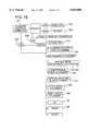
- FIG. 16is a block diagram illustrating software process steps.
- the present tissue analysis systemis especially suitable for use at feedlots for measuring particular tissue characteristics of large numbers of livestock using tissue analysis devices, such as ultrasound devices. It will be apparent that the apparatus can be used in combination with other livestock measuring systems for measuring other animal characteristics.
- the tissue analysis systemhas been designed so that positioning the feed animal, dispensing conductive fluid onto the animal, taking accurate tissue measurements, recording the data and resetting the computer can be done manually and take less than about 30 seconds, and more typically about 15 seconds, for each animal.
- the tissue analysis systemcan be largely automated so an operator can control the functions of the apparatus remotely or place virtually the entire system under the control of computer.
- the present inventioncan be used to measure meat characteristics of many species, it is particularly useful for measuring backfat, intramuscular fat and muscle of cattle.
- an ultrasound transducerhousing for the transducer and oil dispensing system designed primarily so that an operator may manually position the transducer on a feed animal. Thereafter, an automated system for delivering an animal to the tissue analysis zone, and for automated positioning of tissue analysis device or devices on the animal, is described.
- FIG. 1shows a feed animal 10 positioned in a feedlot stall 12. Adjacent the stall is an operator 14. Operator 14 holds and operates both the switch unit 16, as well as the handpiece 18, of the present apparatus. Operator 14 also can view ultrasound images on monitor 20 during the measurement process.
- FIG. 2is a block diagram which illustrates certain components for an embodiment of the present invention.
- FIG. 2also illustrates certain fluid and electric interconnections between these components.
- Power source 22is electrically coupled to each unit requiring power. More specifically, power source 22 is electrically coupled to control computer 24 by cable 26, to ultrasound computer 28 by cable 30, to input/output module 32 by cable 34, and to pump 36 using cable 38.
- Pump 36is controlled by pump control 40, which is electrically coupled to a three-way solenoid valve 42 by cable 44.
- a data cable 46interconnects control computer 24 and ultrasound computer 28.
- FIG. 2also illustrates that the ultrasound computer 28 is electrically coupled to switch unit 16 by cable 48.
- Input/output module 32also is electrically coupled to the handpiece 18 by cable 50.
- Pump 36is fluidly coupled to reservoir 52, which contains a conductive fluid, by fluid conduit 54. Pump 36 is further fluidly coupled to switch unit 16 by fluid line 56. As shown in FIG. 2, a quick disconnect 58 may be placed in fluid line 56. This quick disconnect 58 is provided solely for convenience, and allows the pump fluid line 56 to be quickly disconnected from handpiece 18.
- Each of the individual linesnamely electric cables 48, 50, and fluid line 56, are interfaced with the handpiece 18 by switch unit 16.
- Each of the components of the apparatuscan be individually actuated using the switches 60, 62 and 64 on switch unit 16. Thus, by depressing the appropriate switch, each function of the apparatus can be actuated.
- Power source 22is a conventional piece of equipment that can be obtained commercially. Virtually any power source now known or hereafter developed that can safely power sensitive electronic apparatuses can be used to practice the invention.
- Control computer 24also is a conventional piece of equipment, and any computer which has sufficient capability to control and interface with ultrasound computer 28 will suffice.
- a control computer 24 suitable for thisis an IBM PC.
- Control computer 24controls certain functions of the ultrasound computer 28.
- Commercial softwareis available for operating the control computer 24 to control ultrasound computer 28.
- software suitable for this operationis sold by Animal Ultrasound Services, Inc., of Ithaca, N.Y.
- the present apparatusoperates by generating and transmitting into livestock an ultrasound energy pulse.
- This energy pulseis produced and controlled by ultrasound computer 28 and ultrasound transducer 66.
- ultrasound computer 28and ultrasound transducer 66.
- Each of these componentscan be purchased.
- An ultrasound apparatusthat can be used to practice the invention is an ALOKA 500 V Ultrasound Computer.
- the ALOKA 500 Vis purchased in combination with an ultrasound transducer 66 and transducer cable 68 for coupling the transducer 66 to the computer 28.
- Input/output module 32controls the signals input to and from computer 24 and to the components housed in handpiece 18.
- the I/O module 32is a conventional piece of equipment, and virtually any input/output module 32 will suffice for this invention.
- One prototype of the inventionwas assembled using an OPTO 22 I/O board.
- the OPTO 22 I/O boardincludes: a 1AC5Q input module; a PB16HQ circuit board; a B1 brainboard; a PBSA PP/S power supply; and an OAC5Q output module.
- a pump 36pumps conductive liquid to handpiece 18.
- the conductive liquidis contained in reservoir 52. Any conductive liquid likely will work for the present invention. The selection of a suitable conductive liquid will best be decided by considering, inter alia, the conductivity of the liquid, the expense of the liquid, the availability of the liquid and the toxicity of the liquid. Solely by way of example, suitable conductive liquids may be selected from the group of conductive liquids consisting of water, vegetable oil and mineral oil.
- Pump 36is liquidly to conductive liquid reservoir 52 using liquid connected conduit 54, which was made from flexible TIGON tubing.
- a pressure equalization tube 70also made from TIGON tubing, couples the liquid reservoir 52 and the pump 36. Pressure equalization tube 70 equalizes the pressure between the pump 36 and the reservoir 52 when the pump 36 is not in operation. This helps prevent liquid leaks from reservoir 52.
- Conductive liquidis dispensed from reservoir 52 upon actuation of the pump 36.
- Liquid dispensationis controlled by a three-way solenoid valve 42, which is electrically coupled to pump control 40.
- Three-way valve 42can be electrically actuated by switch 60, which is housed in switch unit 16. This dispenses conductive liquid from reservoir 52 through liquid conduits 54 and 56 to handpiece 18.
- the solenoid valveis open to pressure equalization tube 70 to equalize the pressure between the pump 36 and reservoir 52.
- Liquid back flow from handpiece 18can be checked by a check valve 72, which is mechanically coupled to the handpiece 18.
- FIG. 3is a schematic diagram of the switch unit 16, handpiece 18, cables 48, 50, and liquid conduit 56.
- FIG. 3shows transducer 66 separated from handpiece 18.
- FIG. 3further shows that ultrasound transducer 66 is surrounded by a clear protective housing 74.
- Housing 74performs at least two functions. First, housing 74 protects ultrasound transducer 66 from contact damage. Furthermore, protective housing 74 facilitates the positioning of transducer 66 in handpiece 18 as described below.
- the protective housing 74 in a prototype illustrated in FIG. 3was made from TIGON tubing sized to tightly receive transducer 66 therein.
- FIG. 4is a schematic top plan view and FIG. 5 is an end view illustrating switch unit 16.
- switch unit 16was made from a polypropylene block that was machined to include passages 76 and 78 therethrough.
- Conduit 76provides a passage through switch unit 16 for liquid line 56.
- Passage 78provides a passage through switch unit 16 for electric cables 48 and 50.
- Switch unit 16includes three switches 60, 62 and 64. The switches include conductive liquid switch 60, trigger switch 62 for commanding the computer to read and analyze the image, and reset switch 64 for clearing a previous reading to prepare for rereading an animal or reading a new animal. These switches and their functions also are illustrated in FIG. 9.
- Switch 60actuates liquid pump 36 so that conductive liquid from reservoir 52 is pumped through liquid line 56 and into handpiece 18.
- the amount of time that pump 36 operatesis governed by a timer switch on pump 36 (not shown).
- pump 36is induced to pump conductive liquid from reservoir 52 for the period of time allowed by the timer switch on the pump.
- the pump 36is actuated for a period of less than about 5 seconds, and typically about 3 seconds, during which time less than about 50 milliliters, and more typically about 30 milliliters, is pumped from reservoir 52 to the handpiece 18.
- a second switch 62is electrically coupled to the ultrasound computer 28 by cable 48.
- Switch 62activates the computer 28 to read and analyze the ultrasound image that is produced by transducer 66 as displayed on monitor 20.
- operator 14depresses switch 62 to cause the computer 28 to read the ultrasound image.
- Switch 64is a reset switch electrically coupled to input/output module 32 by cable 50. Switch 64 is depressed by operator 14 when the image has been read by computer 28 or when the operator wants to discard a previous reading and record a new reading of a given animal's image. This can include reapplying conductive liquid from the handpiece 18 onto the animal. resets the computer 24 and input/output module 32 this for receiving new information from a different animal 10.
- FIGS. 6-8further illustrate the construction of handpiece 18.
- FIG. 6is a side schematic view of the housing 18. Housing 18 is manufactured for this particular application, and can be manufactured from a number of suitable materials. The embodiment of a prototype illustrated in FIGS. 6-8 was manufactured from polypropylene. A block of polypropylene having suitable dimensions was obtained and then machined to have substantially the appearance illustrated in FIGS. 6-8.
- handpiece 18is machined to include a threaded inlet 80 for receiving liquid line 56. Any suitable means for coupling the liquid line 56 to housing 18 will suffice.
- FIGS. 6-8illustrate a male threaded connection 82 which is inserted into threaded portion 84 of passage 80 to couple liquid line 56 to housing 18.
- Housing 18also is machined to include a passage 86 for interconnecting liquid inlet 80 and a liquid conduit 88. Liquid conduit 86 is closed using a threaded plug 90, and liquid conduit 88 is closed by a threaded plug 92.
- FIG. 7is a bottom plan view and FIG. 8 is an end view of the handpiece 18.
- FIGS. 7 and 8illustrate a longitudinal slot 94 recessed in the bottom surface of the handpiece 18. Slot 94 is sized to receive the transducer 66 and protective cover 74. If, however, the transducer 66 and cover 74 are not received sufficiently tightly in slot 94 to hold the ultrasound transducer 66 securely therein, an additional polypropylene wedge (not shown) can be used to wedge ultrasound transducer 66 and protective cover 74 inside the slot 94.
- FIG. 7also illustrates that leading to and intersecting with the conduit 88 are plural output orifices 96a-96h. These orifices 96a-96h are fed by liquid line 56.
- the conductive liquidflows through the passage 86, into passage 88 and thereafter through the plural orifices 96a-96h and onto animal 10.
- the spacing of these plural orifices 96a-96his not critical.
- the embodiment illustrated in the figureshas a relative spacing of approximately one-half inch between each respective orifice 96a-96h.
- FIG. 7also illustrates that the handpiece 18 includes plural position markings 98a-98e.
- transducer 66 and protective cover 74are positioned in slot 94.
- the transducer 66 and cover 74are firmly wedged into the slot 94 and between side walls 100 and 102.
- a mid-portion of the transducer 66is centered on one of these respective positioning marks 98a-98e depending upon the size of the animal, before the transducer is fixed in its selected position relative to end wall 104. More specifically, the smaller the animal, the closer transducer 66 is positioned to end wall 104 of slot 94.
- Cattleare positioned seriatim in stall 12 during the procedure.
- operator 14positions handpiece 18 on the back of the animal 10.
- the operation of the apparatusis not critically affected by the positioning of the apparatus on the back of the animal, but its positioning is important for obtaining accurate measurement data of a desired internal tissue characteristic.
- the transducer 66preferably is positioned between the twelfth and thirteenth rib, and typically is focused on the rib-eye muscle approximately three-quarters of the way down the muscle.
- a sufficient amount of the conductive liquidis dispensed onto the animal 10 through line 56, passages 86 and 88, and orifices 96a-96h to obtain a clear image omn the monitor 20. If the monitor 20 shows that the transducer 66 is not correctly positioned, the transducer 66 can be removed from slot 94 in the handpiece 18 and repositioned. Once this is done for the first animal in a group of animals of the same type or general size, the transducer 66 will be adjusted for all animals in the group.
- the amount of liquid dispensedis not critical, except that there must be enough to obtain a clear signal from the ultrasound transducer 66.
- Pump 36can be actuated for particular predetermined lengths of time.
- the pump speedalso can be controlled. The combination of controlling the pump speed and liquid dispensation time allows operator 14 to vary the amount of liquid dispensed upon animal 10 with each actuation of switch 60.
- transducer 66positions transducer 66 against the animal 10 over the oil and between the twelfth and thirteenth rib of the animal 10. The transducer 66 is held steady in this position while operator 14 views image monitor 20. Once a suitable image is obtained, operator 14 actuates trigger switch 62, which is electrically coupled to the ultrasound computer 28. By actuating switch 62, ultrasound computer 28 records the image and data, and calculates and records particular measurements of the animal 10. The data acquisition performed by ultrasound computer 28 is controlled by computer 24. Software is commercially available for running computer 24.
- This softwarecan determine certain meat characteristics using the ultrasound data, including backfat, intramuscular marbling, and the area of a fat deposit.
- softwarecan be selected to perform particular measurements on each animal, and measurement data obtained can be displayed on the monitor 20. If insufficient or inaccurate data is received from a reading, the animal can be remeasured. This is done by pressing reset switch 64 and again pressing trigger switch 62 to take a new reading.
- the information obtained for each animal 10is downloaded into computer 24.
- the animal 10is then released from stall 12, and replaced by another.
- the operatorPrior to applying the transducer 66 to the back of the next animal, the operator actuates reset switch 64. This clears the computer 24 and prepares it to receive new data. The process is then repeated.
- the primarily manual method of the present inventiontakes less than about thirty seconds per animal to perform, and more typically takes only about fifteen seconds. This is a significant improvement over prior ultrasound apparatuses available for use in taking animal measurements, which typically require from about forty-five seconds to two minutes. This is an unacceptably long period of time when many animals may need to be measured daily
- FIG. 10illustrates one embodiment of the automated analysis system.
- the systemincludes a conveyor 110, which conveys an animal to a test zone 112 encompassed by a frame 114.
- Components of the analysis systemare attached to frame 114, which supports the equipment adjacent the animal once it enters zone 112.
- a carrier arm 116is coupled to the frame 114 and the other end to a saddle 118. Arm 116 can be actuated to carry the saddle 118 to and away from the animal once it enters zone 112. Coupled to the saddle 118 is an assembly 120 (FIG. 12) which is operably coupled to transducer 66 for positioning it correctly on the animal's back.
- a video camera 122 and video/computer monitor 124are attached to the frame 114 and operably coupled to control computer 24. Video monitor 124 is located for viewing by operators while actuating the conveyor to position the animal in test zone 112, and while positioning the ultrasound transducer to obtain a good ultrasound image. Components of the tissue analysis system and their operation are described in more detail below.
- Feed animalsare conveyed to the tissue analysis zone 112 by a conveyor 110.
- the operatorcan watch the animal's approach on the video monitor 122 and actuate conveyor 110 to correctly position the animal in zone 112.
- computer 24can be placed in control of the conveyor 110 to deliver animals to zone 112.
- Conveyor 110not only delivers the animal from a remote location, but also renders the animal incapable of using its legs to resist.
- Embodiments of conveyors capable of performing both of these functionsare described in Gearn et al.'s U.S. Pat. No. 5,070,818, entitled “Cattle Conveyor," (“Gearn") which is incorporated herein by reference.
- Gearndiscloses a conveyor which supports the animal above the ground at its brisket. This renders the animal incapable of independent movement, and positions all animals to be imaged in the same relative position in zone 112, both especially important for automated imaging of live animals and obtaining meaningful comparison data.
- Head gates(not illustrated in FIG. 10) also can be used to further
- carrier arm 116 and saddle 118for carrying transducer 66 to an animal located in test zone 112 is illustrated in FIGS. 10 and 11.
- Carrier arm 116is pivotably coupled to the frame 114.
- a linear actuator 125such as a hydraulic or pneumatic piston and cylinder. Actuator 125 can be remotely actuated for extending saddle 118 to or away from the animal.
- Saddle 118has three segments: two side frames 126, 128; and center frame 130. Side frames 126 and 128 are pivotably coupled to center frame 130. Center frame 130 contacts the dorsal region of the feed animal when the saddle 118 is properly positioned. Center frame 130 includes a bracket 132 that is attached to carrier arm 116. Carrier arm 116 includes linear actuator 134 which can be remotely actuated for extending or retracting saddle 118. Saddle 118 can be placed on the back of the animal by actuating both linear actuators 125 and 134.
- side frame assemblies 126 and 128are pivoted to closely contact the animal's flanks.
- Attached to the top surface of center saddle frame 130are two brackets 135 and 136.
- Each of the side frames 126 and 128includes a bracket 138, 140, respectively.
- Brackets 135, 136, 138 and 140are attached to two linear actuators 142, 144. By actuating the linear actuators 142, 144, the two side frames 126 and 128 are pivoted to close in or draw away from the animal's flanks.
- the transducer 66must then be properly positioned, such as between the 12th and 13th ribs of cattle, to perform the tissue analysis. This is accomplished using remotely actuated slidable frames and a pivot frame to which the transducer is operably coupled.
- the term "positioner”refers generally to arm 116, operably coupled linear actuators 125 and 134, as well as to assemblies used to position the transducer relative to the animal.
- One such assemblyreferred to herein as a “transducer positioner,” is illustrated as assembly 120 in FIGS. 12 and 13.
- Transducer positioner 120is attached to side frame 126.
- Transducer positioner 120includes a longitudinal slide frame 146.
- Longitudinalwhen used in reference to positioning the transducer 66, refers to anterior and posterior movement generally parallel to the spine of the animal, i.e., towards the head (cephalad) or the tail (caudad).
- Longitudinal slide frame 146has two cylindrical brackets 148, 150 attached.
- Linear actuator 156is attached to longitudinal slide frame 146 by bracket 160 and to slide frame 162 by bracket 158. Actuator 156 can be remotely actuated for sliding the longitudinal slide frame 146 on brackets 148, 150 along the slide rods 152, 154, fore and aft of the animal.
- FIGS. 12 and 13also show that the longitudinal slide frame 146 is mounted on dorsal/ventral slide frame 162, which is constructed similarly to the frame 146, and which is mounted on side frame 126.
- “dorsal/ventral”refers to movement along the flanks of the animal and towards either the back (dorsal) or stomach (ventral).
- Slide frame 162includes two cylindrical passages 164, 166 for receiving slide rods 168, 170, each of which is anchored to frame 126.
- a linear actuator 172is attached to frame 126 and to dorsal/ventral slide frame 162. Actuator 172 can be remotely actuated for sliding the dorsal/ventral slide frame 162 along the slide rods 168, 170.
- FIGS. 12 and 13further illustrate that the slide frame 162 houses a pivot assembly 174. Attached to pivot assembly 174 are pivot assembly arms 176. Slide frame 146 further includes pivot assembly brackets 178. Pivot assembly 174 is pivotally coupled by arms 176 to assembly brackets 178 using couplers 180. Linear actuator 182 is attached to an arm 176 by bracket 184 and to the longitudinal slide frame 146 by bracket 186. Actuator 182 pivots pivot assembly 174 to control the pitch of the transducer 66, i.e., movement towards and away from the side of the animal.
- Pivot assembly 174also includes a transducer bracket 188 for coupling the transducer 66 to the pivot assembly 174.
- transducer 66is coupled to a transducer housing 190.
- Housing 190is constructed similarly to housing 74, but is designed to be received by bracket 188.
- Housing 190is pivotally coupled to transducer bracket 188 as shown in FIG. 13.
- a linear actuator 192is coupled to the transducer housing 190 by bracket 194 and to pivot assembly 174 by pivot assembly bracket 196.
- Actuator 192can be remotely actuated to control the roll of assembly 174 (i.e., anterior and posterior pivoting of the transducer face) and hence the roll of transducer 66.
- FIG. 14illustrates joy-stick controls 198, 200 that are electrically coupled to the control computer 24 and to each of the components discussed above.
- the illustrated embodiment of joy stick 198includes switches 202, 204 and 206.
- Switches 202, 204 and 206provide for electrically actuating the conveyor 110 (switch 202), linear actuators for placing the saddle 118 on the animal, such as linear actuators 125 and 134 (switch 204), and linear actuators coupled to frames 126 and 128 for squeezing the animal, such as linear actuators 142 and 144 (switch 206).
- joy stick 198itself can be moved to activate the longitudinal linear actuator 156 and the dorsal/ventral linear actuator 172 to position the transducer 66 correctly between the 12th and 13th rib of the animal.
- Joy stick 200includes switches 208, 210 and 212 which are electrically coupled to the pump 36 (switch 208), the transducer 66 (switch 210) and the control computer or transducer computer if a separate computer is used to control the transducer (switch 212).
- Joy stick 200also can be itself moved to actuate linear actuators 182 and 192 to further adjust the pitch and roll of the transducer 66.
- an operator located remotely from test zone 112can actuate each component of the tissue analysis system to: (1) deliver the animal to the test zone 112 by controlling the movement of conveyor 110; (2) actuate linear actuators coupled to carrier arm 116 to lower the saddle 118 onto the animal's back; (3) actuate linear actuators 142 and 144 to pivot the side frames 126, 128 to squeeze the animal's sides; (4) actuate longitudinal linear actuator 156 to correctly position the longitudinal slide frame 146; (5) actuate dorsal/ventral linear actuator 172 to correctly position the dorsal/ventral slide frame 162; (6) actuate the linear actuator 182 to pivot the pivot assembly 174; (6) activate pump 36 to dispense oil onto the animal; (7) activate the transducer 66 to analyze the animal's internal tissue; (8) reset the transducer 66; and (9) control the control computer or the ultrasound computer to reset the transducer 66 for further measurements and to store, record and analyze data.
- FIG. 15illustrates the power connections used to connect each of the components described above. Electrical power is provided to a process control computer 24, a video CPU and an ultrasound transducer CPU 224. The process control computer also is electrically coupled to an input/output device (I/O) 226 for interfacing each of the components comprising the tissue analysis system to the control computer.
- I/Oinput/output device
- the I/O deviceallows communication between the control computer and the following: (1) conveyor 110 for delivering the animal to the tissue analysis zone 112; (2) the linear actuator 125 lowers the saddle 118 onto the animal; (3) linear actuator 134 for extending saddle 118 in a direction transverse to the longitudinal axis of the animal; (4) linear actuators 142 and 144 to adjust side saddle frames 126 and 128; (5) longitudinal linear actuator 156 and dorsal/ventral linear actuator 172 for positioning the transducer 66 to conduct tissue analysis, such as between the 12th and 13th rib of cattle; (6) linear actuators 182 and 192 to adjust the roll and yaw, respectively, of the transducer 66; (7) pump 36 so that conductive fluid may be dispensed from reservoir 52 onto the animal; and (8) transducer 66 to begin tissue analysis, and to reset the transducer for subsequent analysis.
- FIG. 15shows that a switch 228 is included in the system so that the test system can be run either manually or in an automated mode by
- the operation of the present deviceis under the control of a process control computer and video and ultrasound CPUs.
- the steps executed by the software which controls these computersare shown in the block diagram of FIG. 16, which indicates that a menu system likely would be provided for the benefit of the operator.
- ultrasound transducer 66 and video camera 122are turned on at 232, 234.
- Conveyor 110is then started at 236 to position the animal beneath the video camera 122. Incremental adjustments to the animal's position can be made and such adjustments monitored at 238 in video monitor 124 by intermittently activating conveyor 110 via switch 240 until the animal is correctly positioned in test zone 112 for receiving the saddle 118.
- Linear actuatorsare then activated to lower the saddle 118 onto the animal and squeeze the animal's sides at 242.
- Pump 36is then activated at 244 to dispense conductive liquid on the back of the animal from reservoir 52.
- transducer 66is then activated at 246 and the tissue image displayed on video monitor 124.
- a determinationis then made, either by the operator or by the control computer, whether a good ultrasound image is obtained at 248. If the transducer 66 is not producing a good image, then its position is adjusted by actuating any or all of the linear actuators 156, 172, 182 and 192. The positioning of the transducer 66 is continued until a good ultrasound image is obtained at 250.
Landscapes
- Life Sciences & Earth Sciences (AREA)
- Health & Medical Sciences (AREA)
- Engineering & Computer Science (AREA)
- Biophysics (AREA)
- General Health & Medical Sciences (AREA)
- Pathology (AREA)
- Physics & Mathematics (AREA)
- Animal Behavior & Ethology (AREA)
- Veterinary Medicine (AREA)
- Public Health (AREA)
- Surgery (AREA)
- Molecular Biology (AREA)
- Medical Informatics (AREA)
- Heart & Thoracic Surgery (AREA)
- Nuclear Medicine, Radiotherapy & Molecular Imaging (AREA)
- Radiology & Medical Imaging (AREA)
- Biomedical Technology (AREA)
- Environmental Sciences (AREA)
- Food Science & Technology (AREA)
- Computer Vision & Pattern Recognition (AREA)
- Animal Husbandry (AREA)
- Biodiversity & Conservation Biology (AREA)
- Immunology (AREA)
- General Physics & Mathematics (AREA)
- Chemical & Material Sciences (AREA)
- Biochemistry (AREA)
- Analytical Chemistry (AREA)
- Ultra Sonic Daignosis Equipment (AREA)
Abstract
Description
Claims (21)
Priority Applications (3)
| Application Number | Priority Date | Filing Date | Title |
|---|---|---|---|
| US08/748,220US5836880A (en) | 1995-02-27 | 1996-11-12 | Automated system for measuring internal tissue characteristics in feed animals |
| US09/190,916US6200210B1 (en) | 1996-11-12 | 1998-11-12 | Ruminant tissue analysis at packing plants for electronic cattle management and grading meat |
| US09/802,743US6579236B2 (en) | 1996-11-12 | 2001-03-08 | Ruminant tissue analysis at packing plants for electronic cattle management and grading meat |
Applications Claiming Priority (2)
| Application Number | Priority Date | Filing Date | Title |
|---|---|---|---|
| US08/395,931US5573002A (en) | 1995-02-27 | 1995-02-27 | Method and apparatus for measuring internal tissue characteristics in feed animals |
| US08/748,220US5836880A (en) | 1995-02-27 | 1996-11-12 | Automated system for measuring internal tissue characteristics in feed animals |
Related Parent Applications (2)
| Application Number | Title | Priority Date | Filing Date |
|---|---|---|---|
| US08/395,931Continuation-In-PartUS5573002A (en) | 1995-02-27 | 1995-02-27 | Method and apparatus for measuring internal tissue characteristics in feed animals |
| US08/838,768Continuation-In-PartUS6000361A (en) | 1994-10-31 | 1997-04-10 | Cattle Management method and system |
Related Child Applications (2)
| Application Number | Title | Priority Date | Filing Date |
|---|---|---|---|
| US08/838,768Continuation-In-PartUS6000361A (en) | 1994-10-31 | 1997-04-10 | Cattle Management method and system |
| US09/190,916Continuation-In-PartUS6200210B1 (en) | 1996-11-12 | 1998-11-12 | Ruminant tissue analysis at packing plants for electronic cattle management and grading meat |
Publications (1)
| Publication Number | Publication Date |
|---|---|
| US5836880Atrue US5836880A (en) | 1998-11-17 |
Family
ID=46252327
Family Applications (1)
| Application Number | Title | Priority Date | Filing Date |
|---|---|---|---|
| US08/748,220Expired - LifetimeUS5836880A (en) | 1995-02-27 | 1996-11-12 | Automated system for measuring internal tissue characteristics in feed animals |
Country Status (1)
| Country | Link |
|---|---|
| US (1) | US5836880A (en) |
Cited By (52)
| Publication number | Priority date | Publication date | Assignee | Title |
|---|---|---|---|---|
| US6084407A (en)* | 1998-09-10 | 2000-07-04 | Pheno Imaging, Inc. | System for measuring tissue size and marbling in an animal |
| US6082304A (en)* | 1998-07-08 | 2000-07-04 | Crain; Scott L. | Feedyard information system and associated method |
| US6264609B1 (en) | 1999-09-15 | 2001-07-24 | Wake Forest University | Ultrasound apparatus and method for tissue characterization |
| US6288539B1 (en) | 1998-09-10 | 2001-09-11 | Pheno Imaging, Inc. | System for measuring an embryo, reproductive organs, and tissue in an animal |
| US6409665B1 (en)* | 2000-06-01 | 2002-06-25 | Corey D. Scott | Apparatus for applying impedence matching fluid for ultrasonic imaging |
| US6579236B2 (en) | 1996-11-12 | 2003-06-17 | Micro Beef Technologies, Ltd. | Ruminant tissue analysis at packing plants for electronic cattle management and grading meat |
| US6615661B2 (en) | 2001-05-30 | 2003-09-09 | Rethel C. King | Ultrasound sorting of weanling calves and identification of tenderness indicators |
| US20030168014A1 (en)* | 2002-03-11 | 2003-09-11 | Lely Enterprises Ag | A device and an assembly for an animal related action |
| US20040055383A1 (en)* | 2001-05-30 | 2004-03-25 | King Rethel C. | Ultrasound sorting of weanlings and identification of tenderness indicators |
| US20060025702A1 (en)* | 2004-07-29 | 2006-02-02 | Medtronic Xomed, Inc. | Stimulator handpiece for an evoked potential monitoring system |
| US20060054092A1 (en)* | 2004-09-14 | 2006-03-16 | Neal Valencia | Cattle management system and method |
| US20060087039A1 (en)* | 2004-10-22 | 2006-04-27 | Taiwan Semiconductor Manufacturing Company, Ltd. | Ubm structure for improving reliability and performance |
| US20060130777A1 (en)* | 2004-12-17 | 2006-06-22 | Adams William R | Livestock sorting facility |
| US20060185605A1 (en)* | 2004-09-14 | 2006-08-24 | Lextron, Inc. | Cattle Management System and Method |
| US20070021738A1 (en)* | 2005-06-06 | 2007-01-25 | Intuitive Surgical Inc. | Laparoscopic ultrasound robotic surgical system |
| US20070178819A1 (en)* | 2005-02-08 | 2007-08-02 | Mckenna David R | Meat Sortation |
| US20070258625A1 (en)* | 2006-04-03 | 2007-11-08 | Swift & Company | Methods and Systems for Administering a Drug Program Related to Livestock |
| US20080033240A1 (en)* | 2005-10-20 | 2008-02-07 | Intuitive Surgical Inc. | Auxiliary image display and manipulation on a computer display in a medical robotic system |
| US7444961B1 (en) | 2005-04-11 | 2008-11-04 | Ellis James S | Animal sorting and grading system using an internal evaluation to predict maximum value |
| US7509923B2 (en) | 2004-12-17 | 2009-03-31 | Adams Land & Cattle Company | Livestock sorting facility |
| FR2926718A1 (en)* | 2008-01-29 | 2009-07-31 | Frederic Bosler | Continuous and uninterruptance analyzing device for use in e.g. ultrasonograph, has orifice centered on exterior of wall of signal transmitter/receiver probe at right of center of signal transmission and/or reception window |
| US7613330B2 (en) | 2006-04-03 | 2009-11-03 | Jbs Swift & Company | Methods and systems for tracking and managing livestock through the production process |
| US7670292B2 (en) | 2004-11-30 | 2010-03-02 | Micro Beef Technologies, Ltd. | Determining respiratory or circulatory health condition in animals for improved management |
| US7681527B2 (en) | 2005-01-19 | 2010-03-23 | Micro Beef Technologies, Ltd. | Method and system for tracking and managing animals and/or food products |
| US9101397B2 (en) | 1999-04-07 | 2015-08-11 | Intuitive Surgical Operations, Inc. | Real-time generation of three-dimensional ultrasound image using a two-dimensional ultrasound transducer in a robotic system |
| US9138129B2 (en) | 2007-06-13 | 2015-09-22 | Intuitive Surgical Operations, Inc. | Method and system for moving a plurality of articulated instruments in tandem back towards an entry guide |
| US9159126B2 (en) | 2006-04-03 | 2015-10-13 | Jbs Usa, Llc | System and method for analyzing and processing food product |
| US9333042B2 (en) | 2007-06-13 | 2016-05-10 | Intuitive Surgical Operations, Inc. | Medical robotic system with coupled control modes |
| US9345387B2 (en) | 2006-06-13 | 2016-05-24 | Intuitive Surgical Operations, Inc. | Preventing instrument/tissue collisions |
| US9469034B2 (en) | 2007-06-13 | 2016-10-18 | Intuitive Surgical Operations, Inc. | Method and system for switching modes of a robotic system |
| US9492927B2 (en) | 2009-08-15 | 2016-11-15 | Intuitive Surgical Operations, Inc. | Application of force feedback on an input device to urge its operator to command an articulated instrument to a preferred pose |
| US9516996B2 (en) | 2008-06-27 | 2016-12-13 | Intuitive Surgical Operations, Inc. | Medical robotic system providing computer generated auxiliary views of a camera instrument for controlling the position and orienting of its tip |
| US9622826B2 (en) | 2010-02-12 | 2017-04-18 | Intuitive Surgical Operations, Inc. | Medical robotic system providing sensory feedback indicating a difference between a commanded state and a preferred pose of an articulated instrument |
| US9717563B2 (en) | 2008-06-27 | 2017-08-01 | Intuitive Surgical Operations, Inc. | Medical robotic system providing an auxilary view including range of motion limitations for articulatable instruments extending out of a distal end of an entry guide |
| US9718190B2 (en) | 2006-06-29 | 2017-08-01 | Intuitive Surgical Operations, Inc. | Tool position and identification indicator displayed in a boundary area of a computer display screen |
| US9789608B2 (en) | 2006-06-29 | 2017-10-17 | Intuitive Surgical Operations, Inc. | Synthetic representation of a surgical robot |
| US9788909B2 (en) | 2006-06-29 | 2017-10-17 | Intuitive Surgical Operations, Inc | Synthetic representation of a surgical instrument |
| US9795446B2 (en) | 2005-06-06 | 2017-10-24 | Intuitive Surgical Operations, Inc. | Systems and methods for interactive user interfaces for robotic minimally invasive surgical systems |
| US9956044B2 (en) | 2009-08-15 | 2018-05-01 | Intuitive Surgical Operations, Inc. | Controller assisted reconfiguration of an articulated instrument during movement into and out of an entry guide |
| US10008017B2 (en) | 2006-06-29 | 2018-06-26 | Intuitive Surgical Operations, Inc. | Rendering tool information as graphic overlays on displayed images of tools |
| US10258425B2 (en) | 2008-06-27 | 2019-04-16 | Intuitive Surgical Operations, Inc. | Medical robotic system providing an auxiliary view of articulatable instruments extending out of a distal end of an entry guide |
| US10507066B2 (en) | 2013-02-15 | 2019-12-17 | Intuitive Surgical Operations, Inc. | Providing information of tools by filtering image areas adjacent to or on displayed images of the tools |
| US10517569B2 (en) | 2012-05-09 | 2019-12-31 | The Regents Of The University Of Michigan | Linear magnetic drive transducer for ultrasound imaging |
| US11026627B2 (en) | 2013-03-15 | 2021-06-08 | Cadwell Laboratories, Inc. | Surgical instruments for determining a location of a nerve during a procedure |
| US11177610B2 (en) | 2017-01-23 | 2021-11-16 | Cadwell Laboratories, ino. | Neuromonitoring connection system |
| US11253182B2 (en) | 2018-05-04 | 2022-02-22 | Cadwell Laboratories, Inc. | Apparatus and method for polyphasic multi-output constant-current and constant-voltage neurophysiological stimulation |
| US11259870B2 (en) | 2005-06-06 | 2022-03-01 | Intuitive Surgical Operations, Inc. | Interactive user interfaces for minimally invasive telesurgical systems |
| US11443649B2 (en) | 2018-06-29 | 2022-09-13 | Cadwell Laboratories, Inc. | Neurophysiological monitoring training simulator |
| US11992339B2 (en) | 2018-05-04 | 2024-05-28 | Cadwell Laboratories, Inc. | Systems and methods for dynamic neurophysiological stimulation |
| US12239396B2 (en) | 2008-06-27 | 2025-03-04 | Intuitive Surgical Operations, Inc. | Medical robotic system providing an auxiliary view including range of motion limitations for articulatable instruments extending out of a distal end of an entry guide |
| US12266040B2 (en) | 2009-03-31 | 2025-04-01 | Intuitive Surgical Operations, Inc. | Rendering tool information as graphic overlays on displayed images of tools |
| US12357400B2 (en) | 2006-06-29 | 2025-07-15 | Intuitive Surgical Operations, Inc. | Synthetic representation of a surgical robot |
Citations (7)
| Publication number | Priority date | Publication date | Assignee | Title |
|---|---|---|---|---|
| US4359056A (en)* | 1980-06-23 | 1982-11-16 | Renco Corporation | Automatic digital backfat meter |
| US4359055A (en)* | 1980-06-23 | 1982-11-16 | Renco Corporation | Automatic digital backfat meter |
| US4844080A (en)* | 1987-02-19 | 1989-07-04 | Michael Frass | Ultrasound contact medium dispenser |
| US5079951A (en)* | 1990-08-16 | 1992-01-14 | Her Majesty The Queen In Right Of Canada, As Represented By The Minister Of Agriculture | Ultrasonic carcass inspection |
| US5218963A (en)* | 1991-10-15 | 1993-06-15 | Lunar Corporation | Ultrasonic bone analysis device and method |
| US5303708A (en)* | 1992-07-27 | 1994-04-19 | Animal Ultrasound Services, Inc. | Grading of poultry carcasses with ultrasound |
| US5353796A (en)* | 1991-06-28 | 1994-10-11 | Eli Lilly And Company | Non-invasive device and method for grading meat |
- 1996
- 1996-11-12USUS08/748,220patent/US5836880A/ennot_activeExpired - Lifetime
Patent Citations (7)
| Publication number | Priority date | Publication date | Assignee | Title |
|---|---|---|---|---|
| US4359056A (en)* | 1980-06-23 | 1982-11-16 | Renco Corporation | Automatic digital backfat meter |
| US4359055A (en)* | 1980-06-23 | 1982-11-16 | Renco Corporation | Automatic digital backfat meter |
| US4844080A (en)* | 1987-02-19 | 1989-07-04 | Michael Frass | Ultrasound contact medium dispenser |
| US5079951A (en)* | 1990-08-16 | 1992-01-14 | Her Majesty The Queen In Right Of Canada, As Represented By The Minister Of Agriculture | Ultrasonic carcass inspection |
| US5353796A (en)* | 1991-06-28 | 1994-10-11 | Eli Lilly And Company | Non-invasive device and method for grading meat |
| US5218963A (en)* | 1991-10-15 | 1993-06-15 | Lunar Corporation | Ultrasonic bone analysis device and method |
| US5303708A (en)* | 1992-07-27 | 1994-04-19 | Animal Ultrasound Services, Inc. | Grading of poultry carcasses with ultrasound |
Cited By (125)
| Publication number | Priority date | Publication date | Assignee | Title |
|---|---|---|---|---|
| US6579236B2 (en) | 1996-11-12 | 2003-06-17 | Micro Beef Technologies, Ltd. | Ruminant tissue analysis at packing plants for electronic cattle management and grading meat |
| US6082304A (en)* | 1998-07-08 | 2000-07-04 | Crain; Scott L. | Feedyard information system and associated method |
| US6288539B1 (en) | 1998-09-10 | 2001-09-11 | Pheno Imaging, Inc. | System for measuring an embryo, reproductive organs, and tissue in an animal |
| US6084407A (en)* | 1998-09-10 | 2000-07-04 | Pheno Imaging, Inc. | System for measuring tissue size and marbling in an animal |
| US9101397B2 (en) | 1999-04-07 | 2015-08-11 | Intuitive Surgical Operations, Inc. | Real-time generation of three-dimensional ultrasound image using a two-dimensional ultrasound transducer in a robotic system |
| US10433919B2 (en) | 1999-04-07 | 2019-10-08 | Intuitive Surgical Operations, Inc. | Non-force reflecting method for providing tool force information to a user of a telesurgical system |
| US10271909B2 (en) | 1999-04-07 | 2019-04-30 | Intuitive Surgical Operations, Inc. | Display of computer generated image of an out-of-view portion of a medical device adjacent a real-time image of an in-view portion of the medical device |
| US9232984B2 (en) | 1999-04-07 | 2016-01-12 | Intuitive Surgical Operations, Inc. | Real-time generation of three-dimensional ultrasound image using a two-dimensional ultrasound transducer in a robotic system |
| US6264609B1 (en) | 1999-09-15 | 2001-07-24 | Wake Forest University | Ultrasound apparatus and method for tissue characterization |
| US6409665B1 (en)* | 2000-06-01 | 2002-06-25 | Corey D. Scott | Apparatus for applying impedence matching fluid for ultrasonic imaging |
| US20040055383A1 (en)* | 2001-05-30 | 2004-03-25 | King Rethel C. | Ultrasound sorting of weanlings and identification of tenderness indicators |
| US6796184B2 (en) | 2001-05-30 | 2004-09-28 | Rethel C. King | Ultrasound sorting of weanlings and identification of tenderness indicators |
| US6615661B2 (en) | 2001-05-30 | 2003-09-09 | Rethel C. King | Ultrasound sorting of weanling calves and identification of tenderness indicators |
| US20030168014A1 (en)* | 2002-03-11 | 2003-09-11 | Lely Enterprises Ag | A device and an assembly for an animal related action |
| US20060025702A1 (en)* | 2004-07-29 | 2006-02-02 | Medtronic Xomed, Inc. | Stimulator handpiece for an evoked potential monitoring system |
| US11497409B2 (en) | 2004-07-29 | 2022-11-15 | Medtronic Xomed, Inc. | Stimulator handpiece for an evoked potential monitoring system |
| AU2005269287B2 (en)* | 2004-07-29 | 2011-05-12 | Warsaw Orthopedic, Inc. | Stimulator handpiece for an evoked potential monitoring system |
| US10349862B2 (en) | 2004-07-29 | 2019-07-16 | Medtronic Xiomed, Inc. | Stimulator handpiece for an evoked potential monitoring system |
| US10342452B2 (en)* | 2004-07-29 | 2019-07-09 | Medtronic Xomed, Inc. | Stimulator handpiece for an evoked potential monitoring system |
| US7870840B2 (en) | 2004-09-14 | 2011-01-18 | Lextron, Inc. | Cattle management system and method |
| US20060185605A1 (en)* | 2004-09-14 | 2006-08-24 | Lextron, Inc. | Cattle Management System and Method |
| US20060054092A1 (en)* | 2004-09-14 | 2006-03-16 | Neal Valencia | Cattle management system and method |
| US7441515B2 (en) | 2004-09-14 | 2008-10-28 | Lextron, Inc. | Cattle management system and method |
| US7543549B2 (en) | 2004-09-14 | 2009-06-09 | Lextron, Inc. | Cattle management system and method |
| US20090151644A1 (en)* | 2004-09-14 | 2009-06-18 | Neal Valencia | Cattle management system and method |
| US20060087039A1 (en)* | 2004-10-22 | 2006-04-27 | Taiwan Semiconductor Manufacturing Company, Ltd. | Ubm structure for improving reliability and performance |
| US8929971B2 (en) | 2004-11-30 | 2015-01-06 | Mwi Veterinary Supply Co. | Determining respiratory or circulatory health condition in animals for improved management |
| US8282557B2 (en) | 2004-11-30 | 2012-10-09 | Mwi Veterinary Supply Co. | Determining respiratory or circulatory health condition in animals for improved management |
| US7670292B2 (en) | 2004-11-30 | 2010-03-02 | Micro Beef Technologies, Ltd. | Determining respiratory or circulatory health condition in animals for improved management |
| US7931593B2 (en) | 2004-11-30 | 2011-04-26 | Micro Beef Technologies, Ltd. | Determining respiratory or circulatory health condition in animals for improved management |
| US7509923B2 (en) | 2004-12-17 | 2009-03-31 | Adams Land & Cattle Company | Livestock sorting facility |
| US7389743B2 (en) | 2004-12-17 | 2008-06-24 | Adams Land & Cattle Co. | Livestock sorting facility |
| US20060130777A1 (en)* | 2004-12-17 | 2006-06-22 | Adams William R | Livestock sorting facility |
| US8256381B2 (en) | 2005-01-19 | 2012-09-04 | Mwi Veterinary Supply Co. | Method and system for tracking and managing animals and/or food products |
| US7836850B2 (en) | 2005-01-19 | 2010-11-23 | Micro Beef Technologies, Ltd. | Method and system for tracking and managing animals and/or food products |
| US7810451B2 (en) | 2005-01-19 | 2010-10-12 | Micro Beef Technologies, Ltd. | Method and system for tracking and managing animals and/or food products |
| US8037846B2 (en) | 2005-01-19 | 2011-10-18 | Micro Beef Technologies, Ltd. | Method and system for tracking and managing animals and/or food products |
| US7681527B2 (en) | 2005-01-19 | 2010-03-23 | Micro Beef Technologies, Ltd. | Method and system for tracking and managing animals and/or food products |
| US8505488B2 (en) | 2005-01-19 | 2013-08-13 | Mwi Veterinary Supply Co. | Method and system for tracking and managing animals and/or food products |
| US20070178819A1 (en)* | 2005-02-08 | 2007-08-02 | Mckenna David R | Meat Sortation |
| US8147299B2 (en)* | 2005-02-08 | 2012-04-03 | Cargill, Incorporated | Meat sortation |
| US8721405B2 (en)* | 2005-02-08 | 2014-05-13 | Cargill, Incorporated | Meat sortation |
| US9386781B2 (en) | 2005-02-08 | 2016-07-12 | Cargill, Incorporated | Meat sortation |
| US7444961B1 (en) | 2005-04-11 | 2008-11-04 | Ellis James S | Animal sorting and grading system using an internal evaluation to predict maximum value |
| US20070021738A1 (en)* | 2005-06-06 | 2007-01-25 | Intuitive Surgical Inc. | Laparoscopic ultrasound robotic surgical system |
| US11259870B2 (en) | 2005-06-06 | 2022-03-01 | Intuitive Surgical Operations, Inc. | Interactive user interfaces for minimally invasive telesurgical systems |
| US9795446B2 (en) | 2005-06-06 | 2017-10-24 | Intuitive Surgical Operations, Inc. | Systems and methods for interactive user interfaces for robotic minimally invasive surgical systems |
| US12108998B2 (en) | 2005-06-06 | 2024-10-08 | Intuitive Surgical Operations, Inc. | Laparoscopic ultrasound robotic surgical system |
| US10603127B2 (en) | 2005-06-06 | 2020-03-31 | Intuitive Surgical Operations, Inc. | Laparoscopic ultrasound robotic surgical system |
| US10646293B2 (en) | 2005-06-06 | 2020-05-12 | Intuitive Surgical Operations, Inc. | Laparoscopic ultrasound robotic surgical system |
| US11717365B2 (en) | 2005-06-06 | 2023-08-08 | Intuitive Surgical Operations, Inc. | Laparoscopic ultrasound robotic surgical system |
| US11399909B2 (en) | 2005-06-06 | 2022-08-02 | Intuitive Surgical Operations, Inc. | Laparoscopic ultrasound robotic surgical system |
| US11197731B2 (en) | 2005-10-20 | 2021-12-14 | Intuitive Surgical Operations, Inc. | Auxiliary image display and manipulation on a computer display in a medical robotic system |
| US20080033240A1 (en)* | 2005-10-20 | 2008-02-07 | Intuitive Surgical Inc. | Auxiliary image display and manipulation on a computer display in a medical robotic system |
| US8660315B2 (en) | 2006-04-03 | 2014-02-25 | Jbs Usa, Llc | Method for administering a drug program to determine whether an animal has been given a drug |
| US9412160B2 (en) | 2006-04-03 | 2016-08-09 | Jbs Usa, Llc | System and method for analyzing and processing food product |
| US9159126B2 (en) | 2006-04-03 | 2015-10-13 | Jbs Usa, Llc | System and method for analyzing and processing food product |
| US8050462B2 (en) | 2006-04-03 | 2011-11-01 | Jbs Usa, Llc | Methods and systems for administering a drug program |
| US7606394B2 (en) | 2006-04-03 | 2009-10-20 | Jbs Swift & Company | Methods and systems for administering a drug program related to livestock |
| US9135501B2 (en) | 2006-04-03 | 2015-09-15 | Jbs Usa, Llc | Method for administering a drug program to determine whether an animal has been given a drug |
| US7613330B2 (en) | 2006-04-03 | 2009-11-03 | Jbs Swift & Company | Methods and systems for tracking and managing livestock through the production process |
| US20070258625A1 (en)* | 2006-04-03 | 2007-11-08 | Swift & Company | Methods and Systems for Administering a Drug Program Related to Livestock |
| US9881366B2 (en) | 2006-04-03 | 2018-01-30 | Jbs Usa, Llc | System and method for analyzing and processing food product |
| US8379935B2 (en) | 2006-04-03 | 2013-02-19 | Swift & Company | Method for administering a drug program to determine whether an animal has been given a drug |
| US9345387B2 (en) | 2006-06-13 | 2016-05-24 | Intuitive Surgical Operations, Inc. | Preventing instrument/tissue collisions |
| US9789608B2 (en) | 2006-06-29 | 2017-10-17 | Intuitive Surgical Operations, Inc. | Synthetic representation of a surgical robot |
| US9718190B2 (en) | 2006-06-29 | 2017-08-01 | Intuitive Surgical Operations, Inc. | Tool position and identification indicator displayed in a boundary area of a computer display screen |
| US10773388B2 (en) | 2006-06-29 | 2020-09-15 | Intuitive Surgical Operations, Inc. | Tool position and identification indicator displayed in a boundary area of a computer display screen |
| US12357400B2 (en) | 2006-06-29 | 2025-07-15 | Intuitive Surgical Operations, Inc. | Synthetic representation of a surgical robot |
| US10008017B2 (en) | 2006-06-29 | 2018-06-26 | Intuitive Surgical Operations, Inc. | Rendering tool information as graphic overlays on displayed images of tools |
| US10137575B2 (en) | 2006-06-29 | 2018-11-27 | Intuitive Surgical Operations, Inc. | Synthetic representation of a surgical robot |
| US10737394B2 (en) | 2006-06-29 | 2020-08-11 | Intuitive Surgical Operations, Inc. | Synthetic representation of a surgical robot |
| US10730187B2 (en) | 2006-06-29 | 2020-08-04 | Intuitive Surgical Operations, Inc. | Tool position and identification indicator displayed in a boundary area of a computer display screen |
| US11638999B2 (en) | 2006-06-29 | 2023-05-02 | Intuitive Surgical Operations, Inc. | Synthetic representation of a surgical robot |
| US9788909B2 (en) | 2006-06-29 | 2017-10-17 | Intuitive Surgical Operations, Inc | Synthetic representation of a surgical instrument |
| US9801690B2 (en) | 2006-06-29 | 2017-10-31 | Intuitive Surgical Operations, Inc. | Synthetic representation of a surgical instrument |
| US11865729B2 (en) | 2006-06-29 | 2024-01-09 | Intuitive Surgical Operations, Inc. | Tool position and identification indicator displayed in a boundary area of a computer display screen |
| US12295681B2 (en) | 2007-06-13 | 2025-05-13 | Intuitive Surgical Operations, Inc. | Method and system for retracting an instrument into an entry guide |
| US9138129B2 (en) | 2007-06-13 | 2015-09-22 | Intuitive Surgical Operations, Inc. | Method and system for moving a plurality of articulated instruments in tandem back towards an entry guide |
| US11399908B2 (en) | 2007-06-13 | 2022-08-02 | Intuitive Surgical Operations, Inc. | Medical robotic system with coupled control modes |
| US9629520B2 (en) | 2007-06-13 | 2017-04-25 | Intuitive Surgical Operations, Inc. | Method and system for moving an articulated instrument back towards an entry guide while automatically reconfiguring the articulated instrument for retraction into the entry guide |
| US11751955B2 (en) | 2007-06-13 | 2023-09-12 | Intuitive Surgical Operations, Inc. | Method and system for retracting an instrument into an entry guide |
| US9901408B2 (en) | 2007-06-13 | 2018-02-27 | Intuitive Surgical Operations, Inc. | Preventing instrument/tissue collisions |
| US10271912B2 (en) | 2007-06-13 | 2019-04-30 | Intuitive Surgical Operations, Inc. | Method and system for moving a plurality of articulated instruments in tandem back towards an entry guide |
| US12097002B2 (en) | 2007-06-13 | 2024-09-24 | Intuitive Surgical Operations, Inc. | Medical robotic system with coupled control modes |
| US11432888B2 (en) | 2007-06-13 | 2022-09-06 | Intuitive Surgical Operations, Inc. | Method and system for moving a plurality of articulated instruments in tandem back towards an entry guide |
| US10695136B2 (en) | 2007-06-13 | 2020-06-30 | Intuitive Surgical Operations, Inc. | Preventing instrument/tissue collisions |
| US9469034B2 (en) | 2007-06-13 | 2016-10-18 | Intuitive Surgical Operations, Inc. | Method and system for switching modes of a robotic system |
| US10188472B2 (en) | 2007-06-13 | 2019-01-29 | Intuitive Surgical Operations, Inc. | Medical robotic system with coupled control modes |
| US9333042B2 (en) | 2007-06-13 | 2016-05-10 | Intuitive Surgical Operations, Inc. | Medical robotic system with coupled control modes |
| WO2009109707A3 (en)* | 2008-01-29 | 2009-11-12 | Bosler Frederic | Device for ultrasonograph and use thereof |
| FR2926718A1 (en)* | 2008-01-29 | 2009-07-31 | Frederic Bosler | Continuous and uninterruptance analyzing device for use in e.g. ultrasonograph, has orifice centered on exterior of wall of signal transmitter/receiver probe at right of center of signal transmission and/or reception window |
| US10368952B2 (en) | 2008-06-27 | 2019-08-06 | Intuitive Surgical Operations, Inc. | Medical robotic system providing an auxiliary view including range of motion limitations for articulatable instruments extending out of a distal end of an entry guide |
| US11382702B2 (en) | 2008-06-27 | 2022-07-12 | Intuitive Surgical Operations, Inc. | Medical robotic system providing an auxiliary view including range of motion limitations for articulatable instruments extending out of a distal end of an entry guide |
| US11638622B2 (en) | 2008-06-27 | 2023-05-02 | Intuitive Surgical Operations, Inc. | Medical robotic system providing an auxiliary view of articulatable instruments extending out of a distal end of an entry guide |
| US10258425B2 (en) | 2008-06-27 | 2019-04-16 | Intuitive Surgical Operations, Inc. | Medical robotic system providing an auxiliary view of articulatable instruments extending out of a distal end of an entry guide |
| US9516996B2 (en) | 2008-06-27 | 2016-12-13 | Intuitive Surgical Operations, Inc. | Medical robotic system providing computer generated auxiliary views of a camera instrument for controlling the position and orienting of its tip |
| US9717563B2 (en) | 2008-06-27 | 2017-08-01 | Intuitive Surgical Operations, Inc. | Medical robotic system providing an auxilary view including range of motion limitations for articulatable instruments extending out of a distal end of an entry guide |
| US12239396B2 (en) | 2008-06-27 | 2025-03-04 | Intuitive Surgical Operations, Inc. | Medical robotic system providing an auxiliary view including range of motion limitations for articulatable instruments extending out of a distal end of an entry guide |
| US12266040B2 (en) | 2009-03-31 | 2025-04-01 | Intuitive Surgical Operations, Inc. | Rendering tool information as graphic overlays on displayed images of tools |
| US10984567B2 (en) | 2009-03-31 | 2021-04-20 | Intuitive Surgical Operations, Inc. | Rendering tool information as graphic overlays on displayed images of tools |
| US11941734B2 (en) | 2009-03-31 | 2024-03-26 | Intuitive Surgical Operations, Inc. | Rendering tool information as graphic overlays on displayed images of tools |
| US10282881B2 (en) | 2009-03-31 | 2019-05-07 | Intuitive Surgical Operations, Inc. | Rendering tool information as graphic overlays on displayed images of tools |
| US10959798B2 (en) | 2009-08-15 | 2021-03-30 | Intuitive Surgical Operations, Inc. | Application of force feedback on an input device to urge its operator to command an articulated instrument to a preferred pose |
| US10772689B2 (en) | 2009-08-15 | 2020-09-15 | Intuitive Surgical Operations, Inc. | Controller assisted reconfiguration of an articulated instrument during movement into and out of an entry guide |
| US9492927B2 (en) | 2009-08-15 | 2016-11-15 | Intuitive Surgical Operations, Inc. | Application of force feedback on an input device to urge its operator to command an articulated instrument to a preferred pose |
| US10271915B2 (en) | 2009-08-15 | 2019-04-30 | Intuitive Surgical Operations, Inc. | Application of force feedback on an input device to urge its operator to command an articulated instrument to a preferred pose |
| US11596490B2 (en) | 2009-08-15 | 2023-03-07 | Intuitive Surgical Operations, Inc. | Application of force feedback on an input device to urge its operator to command an articulated instrument to a preferred pose |
| US9956044B2 (en) | 2009-08-15 | 2018-05-01 | Intuitive Surgical Operations, Inc. | Controller assisted reconfiguration of an articulated instrument during movement into and out of an entry guide |
| US10828774B2 (en) | 2010-02-12 | 2020-11-10 | Intuitive Surgical Operations, Inc. | Medical robotic system providing sensory feedback indicating a difference between a commanded state and a preferred pose of an articulated instrument |
| US10537994B2 (en) | 2010-02-12 | 2020-01-21 | Intuitive Surgical Operations, Inc. | Medical robotic system providing sensory feedback indicating a difference between a commanded state and a preferred pose of an articulated instrument |
| US9622826B2 (en) | 2010-02-12 | 2017-04-18 | Intuitive Surgical Operations, Inc. | Medical robotic system providing sensory feedback indicating a difference between a commanded state and a preferred pose of an articulated instrument |
| US10517569B2 (en) | 2012-05-09 | 2019-12-31 | The Regents Of The University Of Michigan | Linear magnetic drive transducer for ultrasound imaging |
| US11806102B2 (en) | 2013-02-15 | 2023-11-07 | Intuitive Surgical Operations, Inc. | Providing information of tools by filtering image areas adjacent to or on displayed images of the tools |
| US10507066B2 (en) | 2013-02-15 | 2019-12-17 | Intuitive Surgical Operations, Inc. | Providing information of tools by filtering image areas adjacent to or on displayed images of the tools |
| US11389255B2 (en) | 2013-02-15 | 2022-07-19 | Intuitive Surgical Operations, Inc. | Providing information of tools by filtering image areas adjacent to or on displayed images of the tools |
| US12178606B2 (en) | 2013-03-15 | 2024-12-31 | Cadwell Laboratories, Inc. | Neuromonitoring systems and methods |
| US11026627B2 (en) | 2013-03-15 | 2021-06-08 | Cadwell Laboratories, Inc. | Surgical instruments for determining a location of a nerve during a procedure |
| US11949188B2 (en) | 2017-01-23 | 2024-04-02 | Cadwell Laboratories, Inc. | Methods for concurrently forming multiple electrical connections in a neuro-monitoring system |
| US11177610B2 (en) | 2017-01-23 | 2021-11-16 | Cadwell Laboratories, ino. | Neuromonitoring connection system |
| US11992339B2 (en) | 2018-05-04 | 2024-05-28 | Cadwell Laboratories, Inc. | Systems and methods for dynamic neurophysiological stimulation |
| US11998338B2 (en) | 2018-05-04 | 2024-06-04 | Cadwell Laboratories, Inc. | Systems and methods for dynamically switching output port cathode and anode designations |
| US11253182B2 (en) | 2018-05-04 | 2022-02-22 | Cadwell Laboratories, Inc. | Apparatus and method for polyphasic multi-output constant-current and constant-voltage neurophysiological stimulation |
| US11978360B2 (en) | 2018-06-29 | 2024-05-07 | Cadwell Laboratories, Inc. | Systems and methods for neurophysiological simulation |
| US11443649B2 (en) | 2018-06-29 | 2022-09-13 | Cadwell Laboratories, Inc. | Neurophysiological monitoring training simulator |
Similar Documents
| Publication | Publication Date | Title |
|---|---|---|
| US5836880A (en) | Automated system for measuring internal tissue characteristics in feed animals | |
| US5573002A (en) | Method and apparatus for measuring internal tissue characteristics in feed animals | |
| Houghton et al. | Application of ultrasound for feeding and finishing animals: A review | |
| US5872314A (en) | Method and apparatus for measuring characteristics of meat | |
| US5617864A (en) | Method and apparatus for positioning an ultrasonic transducer and a display screen | |
| Smith et al. | Evaluation of ultrasound for prediction of carcass fat thickness and longissimus muscle area in feedlot steers | |
| Domecq et al. | Validation of body condition scores with ultrasound measurements of subcutaneous fat of dairy cows | |
| US6200210B1 (en) | Ruminant tissue analysis at packing plants for electronic cattle management and grading meat | |
| Robinson et al. | Live animal measurement of carcass traits by ultrasound: assessment and accuracy of sonographers | |
| McLaren et al. | A study of operator effects on ultrasonic measures of fat depth and longissimus muscle area in cattle, sheep and pigs | |
| US6579236B2 (en) | Ruminant tissue analysis at packing plants for electronic cattle management and grading meat | |
| EP2027770B1 (en) | Method and apparatus for the automatic grading of condition of livestock | |
| US4825711A (en) | Probe unit for automatic determination of quality properties of meat | |
| Whittaker et al. | Principles of ultrasound and measurement of intramuscular fat | |
| Herring et al. | Comparison of four real-time ultrasound systems that predict intramuscular fat in beef cattle | |
| Szabo et al. | The application of digital imaging techniques in the in vivo estimation of the body composition of pigs: a review | |
| US20070022967A1 (en) | System and method for measuring animals | |
| US6517487B1 (en) | Ultrasonic densitometer with opposed single transducer and transducer array | |
| Cross et al. | Objective measurements of carcass and meat quality | |
| US6170335B1 (en) | Method and apparatus for measuring the characteristics of meat | |
| Liu et al. | Pork carcass evaluation with an automated and computerized ultrasonic system | |
| US5316003A (en) | Method and apparatus for positioning an ultrasonic transducer for longitudinal scanning of an animal or carcass | |
| Moeller | Evolution and use of ultrasonic technology in the swine industry | |
| US6591221B1 (en) | Method and device for assessing cattle | |
| Hopkins et al. | Changes in fat depths and muscle dimensions in growing lambs as measured by real-time ultrasound |
Legal Events
| Date | Code | Title | Description |
|---|---|---|---|
| AS | Assignment | Owner name:MICRO CHEMICAL, INC., TEXAS Free format text:ASSIGNMENT OF ASSIGNORS INTEREST;ASSIGNOR:PRATT, WILLIAM C.;REEL/FRAME:008390/0865 Effective date:19970219 | |
| STCF | Information on status: patent grant | Free format text:PATENTED CASE | |
| AS | Assignment | Owner name:MICRO BEEF TECHNOLOGIES, LTD., TEXAS Free format text:CHANGE OF NAME;ASSIGNOR:MICRO CHEMICAL, INC.;REEL/FRAME:012607/0384 Effective date:20001018 | |
| FPAY | Fee payment | Year of fee payment:4 | |
| AS | Assignment | Owner name:MICRO BEEF TECHNOLOGIES, INC., TEXAS Free format text:CHANGE OF NAME;ASSIGNOR:MICRO CHEMICAL, INC.;REEL/FRAME:013578/0760 Effective date:19991206 | |
| AS | Assignment | Owner name:BANK OF AMERICA, N.A., CALIFORNIA Free format text:SECURITY AGREEMENT;ASSIGNOR:MICRO BEEF TECHNOLOGIES, LTD.;REEL/FRAME:013691/0619 Effective date:20030110 | |
| FPAY | Fee payment | Year of fee payment:8 | |
| FPAY | Fee payment | Year of fee payment:12 | |
| AS | Assignment | Owner name:MWI VETERINARY SUPPLY CO., IDAHO Free format text:ASSIGNMENT OF ASSIGNORS INTEREST;ASSIGNOR:MICRO BEEF TECHNOLOGIES, LTD.;REEL/FRAME:027913/0213 Effective date:20111031 |