US5836655A - Strap retainer assembly and method - Google Patents
Strap retainer assembly and methodDownload PDFInfo
- Publication number
- US5836655A US5836655AUS08/786,995US78699597AUS5836655AUS 5836655 AUS5836655 AUS 5836655AUS 78699597 AUS78699597 AUS 78699597AUS 5836655 AUS5836655 AUS 5836655A
- Authority
- US
- United States
- Prior art keywords
- strap
- furniture
- insert
- anchor
- anchors
- Prior art date
- Legal status (The legal status is an assumption and is not a legal conclusion. Google has not performed a legal analysis and makes no representation as to the accuracy of the status listed.)
- Expired - Fee Related
Links
- 238000000034methodMethods0.000titleclaimsdescription7
- 230000000717retained effectEffects0.000claimsabstractdescription7
- 239000000463materialSubstances0.000claimsdescription9
- 238000010438heat treatmentMethods0.000claimsdescription2
- 230000001419dependent effectEffects0.000abstractdescription2
- 238000004513sizingMethods0.000abstractdescription2
- 238000004519manufacturing processMethods0.000description3
- 229910052751metalInorganic materials0.000description3
- 239000002184metalSubstances0.000description3
- 229910052782aluminiumInorganic materials0.000description2
- XAGFODPZIPBFFR-UHFFFAOYSA-NaluminiumChemical compound[Al]XAGFODPZIPBFFR-UHFFFAOYSA-N0.000description2
- 230000013011matingEffects0.000description2
- 125000000391vinyl groupChemical group[H]C([*])=C([H])[H]0.000description2
- 229920002554vinyl polymerPolymers0.000description2
- 238000010276constructionMethods0.000description1
- 230000000694effectsEffects0.000description1
- 229920003023plasticPolymers0.000description1
- 229920002994synthetic fiberPolymers0.000description1
- 238000003466weldingMethods0.000description1
Images
Classifications
- A—HUMAN NECESSITIES
- A47—FURNITURE; DOMESTIC ARTICLES OR APPLIANCES; COFFEE MILLS; SPICE MILLS; SUCTION CLEANERS IN GENERAL
- A47C—CHAIRS; SOFAS; BEDS
- A47C31/00—Details or accessories for chairs, beds, or the like, not provided for in other groups of this subclass, e.g. upholstery fasteners, mattress protectors, stretching devices for mattress nets
- A47C31/02—Upholstery attaching means
- A47C31/04—Clamps for attaching flat elastic strips or flat meandering springs to frames
- A—HUMAN NECESSITIES
- A47—FURNITURE; DOMESTIC ARTICLES OR APPLIANCES; COFFEE MILLS; SPICE MILLS; SUCTION CLEANERS IN GENERAL
- A47C—CHAIRS; SOFAS; BEDS
- A47C5/00—Chairs of special materials
- A47C5/04—Metal chairs, e.g. tubular
- A47C5/06—Special adaptation of seat upholstery or fabric for attachment to tubular chairs
Definitions
- This inventionrelates to the construction and manufacture of furniture. More specifically, the present invention relates to a novel strap retaining assembly for use in bridging sections of framed furniture for support of the user.
- Furniture manufacturingrequires structure to support the user of the furniture.
- this structureembodies a frame having springs or coils thereon.
- the frameis upholstered with padding to soften the coils. This is typical of the seat section and back section of this type of furniture. Thereafter, cushions may be added to further soften the furniture and to add decorative design.
- Another type of furniture that incorporates a fixed frame to support the useris one which uses a metal tube that may be extruded.
- the frameis fashioned to form the desired skeletal structure, for example, a seating device.
- the seat portion and/or back portion or side portions of this furnituremay be completed with fixed slats that are welded, or secured by other means, into place to support the user of the device. Cushions may be added thereon to soften the slats and add design features.
- Another method of bridging the furniture sections above referred toemploys the use of a synthetic strapping, such as vinyl, that is drawn taught from side to side, for example, the seat portion of the seating device.
- This strappingmay be used for the back portion or the side portions of the desired furniture.
- Typical applications of strapping of this naturerequire that the strapping be wrapped around the frame and drawn taughtly across the frame where the synthetic material is wrapped about the other side of the frame. The strapping material is then secured, by example, by being screwed into the frame itself.
- Furniture of this natureis known to exist in the form of "patio" or “pool” furniture which is further known to be less stylish than other types of outdoor or indoor furniture.
- the present inventionovercomes the aforementioned problems and undesirable elements of the prior art by providing a strap retainer assembly for furniture.
- the strap retainer assemblycomprises an anchor and insert wherein in the anchor is permanently secured to the frame of the furniture.
- the anchorhas an opening large enough to accept the insert, yet be positioned such that when the insert is pulled laterally, it is retained by the anchor.
- the insertcomprises a strap having opposed ends; each end is looped and secured by a clip.
- the clipis the portion of the insert placed into the opening of the anchor hereinabove mentioned.
- the frameis fitted with opposing anchors.
- the insertis heated resulting in a pliable strap.
- Each clip of the insertis placed in the opposing anchors. When the strap medium cools, it shrinks causing a taught horizontal fit, thus bridging the furniture frame.
- the number of inserts placed within the anchors on furnitureis dependent upon the sizing (width) of the inserts and the overall length of the anchors.
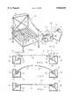
- FIG. 1is a perspective view of the strap retainer assembly as used for furniture
- FIG. 2is a fragmented, perspective view of the anchor and insert of the present invention taken along Line 2--2 of FIG. 1;
- FIG. 3is a cross section view of opposed anchors of the present invention showing a broken side view of the insert of said invention
- FIG. 4is a broken, side view showing a heated insert of the present invention being introduced into a cross section view of opposed anchors of the present invention.
- FIG. 5is a broken side view of the cooled insert of the present invention set into a cross section view of opposed anchors of the present invention.
- furniture 10is constructed of a frame 12. There exists on furniture l a seat frame 14 and a back frame 16.
- the seat frame 14is comprised of opposed supports 18 and 20, respectively.
- FIGS. 2 through 5depict a strap retainer assembly 24.
- the assemblycomprises, in part, an anchor 30.
- Anchor 30has a base 32, and opposed front 36 and back 38 sections. Front section has a top 40 and back section has a top 42. The back section 38 has a greater length than that of the front section 36.
- Anchor 30may be made of a material capable of supporting the weight of a user of furniture, such as aluminum. It may be extruded to a particular shape or may be die cast.
- Anchor 30is substantially rectangular in shape and may be generally described as having an X axis which runs generally horizontally and a Y axis which runs generally vertically. Along the X axis of anchor 30 is cavity 50 which runs through the entire length of anchor 30.
- the cavity 50has a shape capable of accepting a matable insert 70 hereinbelow described. It is preferred that the shape of cavity 50 be generally round or annular. Cavity 50 has an opening 52 for accepting the aforementioned insert 70.
- the cavity 50has a center point which meets at the intersection of the X and Y axes of anchor 30. This center point is below the top 40 of the anchor 30. The center point along the Y axis is displaced away from back section 38 and toward front section 36 of anchor 30. A representative position of the center point may be seen in FIG. 3.
- opening 52 of cavity 50is diagonal to that of the X axis and Y axis of anchor 30. Opening 52 needs to be large enough to accept insert 70. However, it has been determined, and is disclosed here, that the opening 52 should be greater than 100 degrees measured from the center point of cavity 50. The preferred embodiment though is that the opening have an expanse of 111 degrees from the edge 54 of top 40 to edge 56 of top 42. It is further preferred that edges 54 and 56 comprise right angles and be "sharp" rather than being smooth or rounded.
- strap 60has opposed ends thereof which terminate in loops 72.
- the strapmay be fashioned of any common material typically associated with the manufacture of furniture. This invention contemplates the use of vinyl as the material for strap 60.
- Each loopis secured with a clip 74 and retained therein, and, in such form, the insert 70 is created.
- Clip 74is sized to engage loosely initially within cavity 50 and may be made of a material, such as a metal or plastic, that has sufficient strength to retain the looped strap 60 when pulled.
- the preferred material used for the clip 74is aluminum or another workable metal.
- the anchor 30is permanently secured thereon to any bar, for example, seat support 18, by means of welding, screwing or other suitable means.
- the anchor 30may also be an integral component of the frame 12.
- a second anchor 30is secured on to an opposed facing support 20.
- the cavities 50 of each anchor 30are positioned to face each other, respectively.
- the strap 60has a length that, when at room temperature, is taught across the seat frame 14 or back frame 16, for example, of frame 12.
- the insert 70, and thus strap 60is heated.
- One method of heating the insert 70is by placing it in a hot air oven. It is preferred that insert 70 is heated at a temperature of 180-200 degrees F. for five (5) minutes.
- the pliability of the heated, stretched, strap 60permits the clips 74 of insert 70 to engage loosely initially within the cavities 50 of the anchors 30. When strap 60 cools, it looses its heated pliability and attempts to shrink to its unheated (room temperature) length.
- strap 60As strap 60 cools and shrinks, it pulls insert 70 along the X axis (for seat frame 14 or Y axis for back frame 16) of anchor 30 and parallel thereto. Each clip 74 of insert 70 then comes into contact with edge 54 along the X axis which then creates an upward movement of clip 74 into edge 56. This upward movement of clip 74 prevents insert 70 from slipping out of the anchor 30.
- the resultant effectis that strap 60 is prevented from shrinking completely to a room temperature length and is retained within the cavity 50 of anchor 30 forming a bridge across the furniture frame 12. Any desired number of straps 60, whose combined width does not exceed the length of the anchors 30, may be fashioned across the frame 12 to provide a complete bridge thereover sufficient to hold the weight of a user. As a result, variable strap spacing is achieved.
- cavity 50is generally round and that of mating member clip 74 is similarly round, any shape of these mating members can be incorporated within the subject of this invention.
Landscapes
- Clamps And Clips (AREA)
Abstract
Description
Claims (8)
Priority Applications (1)
| Application Number | Priority Date | Filing Date | Title |
|---|---|---|---|
| US08/786,995US5836655A (en) | 1995-03-27 | 1997-01-23 | Strap retainer assembly and method |
Applications Claiming Priority (2)
| Application Number | Priority Date | Filing Date | Title |
|---|---|---|---|
| US41082295A | 1995-03-27 | 1995-03-27 | |
| US08/786,995US5836655A (en) | 1995-03-27 | 1997-01-23 | Strap retainer assembly and method |
Related Parent Applications (1)
| Application Number | Title | Priority Date | Filing Date |
|---|---|---|---|
| US41082295AContinuation | 1995-03-27 | 1995-03-27 |
Publications (1)
| Publication Number | Publication Date |
|---|---|
| US5836655Atrue US5836655A (en) | 1998-11-17 |
Family
ID=23626376
Family Applications (1)
| Application Number | Title | Priority Date | Filing Date |
|---|---|---|---|
| US08/786,995Expired - Fee RelatedUS5836655A (en) | 1995-03-27 | 1997-01-23 | Strap retainer assembly and method |
Country Status (1)
| Country | Link |
|---|---|
| US (1) | US5836655A (en) |
Cited By (20)
| Publication number | Priority date | Publication date | Assignee | Title |
|---|---|---|---|---|
| US6209610B1 (en)* | 1994-07-28 | 2001-04-03 | 420820 Ontario Limited | Retractable screen system and improvements therefor |
| US6405781B2 (en) | 1994-07-28 | 2002-06-18 | 420820 Ontario Limited | Screen cassette and compatible framing section therefor |
| US6523904B1 (en)* | 1999-11-17 | 2003-02-25 | Telescope Casual Furniture, Inc. | Outdoor furniture construction |
| US20030155798A1 (en)* | 2002-02-06 | 2003-08-21 | Moeller Marine Products | Boat comfort seat assembly |
| US20040000808A1 (en)* | 2002-05-01 | 2004-01-01 | Maloney Timothy J. | Furniture structure |
| US20040108767A1 (en)* | 2002-12-06 | 2004-06-10 | Zhao Quan You | U-clip and assembly system |
| US20060220435A1 (en)* | 2005-04-04 | 2006-10-05 | Carter Howard S | Modular furniture attachment strap |
| US7226130B2 (en) | 2002-09-12 | 2007-06-05 | Steelcase Development Corporation | Seating with comfort surface |
| US20070278840A1 (en)* | 2006-06-01 | 2007-12-06 | Oliver Wang | System and method for mounting wicker |
| US9370247B1 (en)* | 2011-09-12 | 2016-06-21 | John W. Caldwell | Web-strapped furniture, web-strapping for furniture, and methods for web-strapping furniture |
| US20160174718A1 (en)* | 2014-12-19 | 2016-06-23 | Emu Group S.P.A. | Support equipment for supporting a person at rest having a rigid supporting structure with supporting elements |
| CN105768653A (en)* | 2016-04-15 | 2016-07-20 | 李红广 | Rattan weaving structure and rattan chair made by means of same |
| US9759248B1 (en)* | 2016-03-11 | 2017-09-12 | Yotrio Group Co., Ltd. | Chair with plug type connection structure |
| US9986845B1 (en)* | 2017-01-10 | 2018-06-05 | Shinmaofeng Office Furniture Co., Ltd. | Net fixing structure of chair |
| US10463170B2 (en) | 2015-09-09 | 2019-11-05 | Kids Ii, Inc. | Collapsible play yard |
| USD866995S1 (en) | 2016-09-08 | 2019-11-19 | Kids2, Inc. | Play yard |
| US11202508B2 (en) | 2017-08-28 | 2021-12-21 | Agio International Co., Ltd | Q-shaped wicker furniture |
| US11517110B2 (en)* | 2020-04-28 | 2022-12-06 | Zhejiang Zhendong Leisure Products Co., Ltd. | Woven structure and chair with the same |
| US11643865B2 (en) | 2018-01-23 | 2023-05-09 | Pella Corporation | Roller assembly and screen end retention features for a hidden screen assembly and a fenestration assembly |
| US12000208B2 (en) | 2020-01-31 | 2024-06-04 | Pella Corporation | Integrated pleated screen assembly |
Citations (4)
| Publication number | Priority date | Publication date | Assignee | Title |
|---|---|---|---|---|
| US1246544A (en)* | 1916-02-03 | 1917-11-13 | Marcel Dufour | Stretcher. |
| US2839126A (en)* | 1953-12-14 | 1958-06-17 | Ralph A O'neill | Attachment of webbing strip or the like, and novel frame support and attaching means |
| US3107944A (en)* | 1961-09-14 | 1963-10-22 | Prestige Furniture Corp | Seat construction for articles of furniture |
| DE3211117A1 (en)* | 1982-03-26 | 1983-10-06 | Oke Heyde & Tillner V D | Arrangement for attaching upholstery belts |
- 1997
- 1997-01-23USUS08/786,995patent/US5836655A/ennot_activeExpired - Fee Related
Patent Citations (4)
| Publication number | Priority date | Publication date | Assignee | Title |
|---|---|---|---|---|
| US1246544A (en)* | 1916-02-03 | 1917-11-13 | Marcel Dufour | Stretcher. |
| US2839126A (en)* | 1953-12-14 | 1958-06-17 | Ralph A O'neill | Attachment of webbing strip or the like, and novel frame support and attaching means |
| US3107944A (en)* | 1961-09-14 | 1963-10-22 | Prestige Furniture Corp | Seat construction for articles of furniture |
| DE3211117A1 (en)* | 1982-03-26 | 1983-10-06 | Oke Heyde & Tillner V D | Arrangement for attaching upholstery belts |
Cited By (28)
| Publication number | Priority date | Publication date | Assignee | Title |
|---|---|---|---|---|
| US6405781B2 (en) | 1994-07-28 | 2002-06-18 | 420820 Ontario Limited | Screen cassette and compatible framing section therefor |
| US6209610B1 (en)* | 1994-07-28 | 2001-04-03 | 420820 Ontario Limited | Retractable screen system and improvements therefor |
| US6523904B1 (en)* | 1999-11-17 | 2003-02-25 | Telescope Casual Furniture, Inc. | Outdoor furniture construction |
| US20030155798A1 (en)* | 2002-02-06 | 2003-08-21 | Moeller Marine Products | Boat comfort seat assembly |
| US6733084B2 (en)* | 2002-02-06 | 2004-05-11 | Moeller Marine Products | Boat comfort seat assembly |
| US7066553B2 (en)* | 2002-05-01 | 2006-06-27 | Fincastle County Chairworks, Llc | Furniture structure |
| US20040000808A1 (en)* | 2002-05-01 | 2004-01-01 | Maloney Timothy J. | Furniture structure |
| US7226130B2 (en) | 2002-09-12 | 2007-06-05 | Steelcase Development Corporation | Seating with comfort surface |
| US7360835B2 (en) | 2002-09-12 | 2008-04-22 | Steelcase Inc. | Seating with comfort surface |
| US20040108767A1 (en)* | 2002-12-06 | 2004-06-10 | Zhao Quan You | U-clip and assembly system |
| US20060220435A1 (en)* | 2005-04-04 | 2006-10-05 | Carter Howard S | Modular furniture attachment strap |
| US7448689B2 (en) | 2005-04-04 | 2008-11-11 | La-Z-Boy Incorporated | Modular furniture attachment strap |
| US20070278840A1 (en)* | 2006-06-01 | 2007-12-06 | Oliver Wang | System and method for mounting wicker |
| US7481495B2 (en)* | 2006-06-01 | 2009-01-27 | Agio International Company, Limited | System and method for mounting wicker |
| US9370247B1 (en)* | 2011-09-12 | 2016-06-21 | John W. Caldwell | Web-strapped furniture, web-strapping for furniture, and methods for web-strapping furniture |
| US9700141B2 (en)* | 2014-12-19 | 2017-07-11 | Emu Group S.P.A. | Support equipment for supporting a person at rest having a rigid supporting elements |
| US20160174718A1 (en)* | 2014-12-19 | 2016-06-23 | Emu Group S.P.A. | Support equipment for supporting a person at rest having a rigid supporting structure with supporting elements |
| US10463170B2 (en) | 2015-09-09 | 2019-11-05 | Kids Ii, Inc. | Collapsible play yard |
| US9759248B1 (en)* | 2016-03-11 | 2017-09-12 | Yotrio Group Co., Ltd. | Chair with plug type connection structure |
| CN105768653A (en)* | 2016-04-15 | 2016-07-20 | 李红广 | Rattan weaving structure and rattan chair made by means of same |
| USD866995S1 (en) | 2016-09-08 | 2019-11-19 | Kids2, Inc. | Play yard |
| US9986845B1 (en)* | 2017-01-10 | 2018-06-05 | Shinmaofeng Office Furniture Co., Ltd. | Net fixing structure of chair |
| US11202508B2 (en) | 2017-08-28 | 2021-12-21 | Agio International Co., Ltd | Q-shaped wicker furniture |
| US11643865B2 (en) | 2018-01-23 | 2023-05-09 | Pella Corporation | Roller assembly and screen end retention features for a hidden screen assembly and a fenestration assembly |
| US11643864B2 (en) | 2018-01-23 | 2023-05-09 | Pella Corporation | Screen edge retention and screen rethreading features for a hidden screen assembly and a fenestration assembly |
| US12173553B2 (en) | 2018-01-23 | 2024-12-24 | Pella Corporation | Screen edge retention and screen rethreading features for a hidden screen assembly and a fenestration assembly |
| US12000208B2 (en) | 2020-01-31 | 2024-06-04 | Pella Corporation | Integrated pleated screen assembly |
| US11517110B2 (en)* | 2020-04-28 | 2022-12-06 | Zhejiang Zhendong Leisure Products Co., Ltd. | Woven structure and chair with the same |
Similar Documents
| Publication | Publication Date | Title |
|---|---|---|
| US5836655A (en) | Strap retainer assembly and method | |
| JP3821246B2 (en) | Plane for seats on armchairs, sofas, chairs, etc. with a fixing device that uses its own tension to fix the belt to the support frame | |
| US7448197B2 (en) | Method of making furniture with synthetic woven material | |
| US5178306A (en) | Hanger with clips | |
| US3230011A (en) | Seating | |
| US4516305A (en) | Webbing tensioning method | |
| US4852228A (en) | Method of Manufacturing a vehicle seat with mold-in-face suspension system | |
| US5868694A (en) | Lower back support apparatus | |
| CA1274166A (en) | Chair construction | |
| US20200081267A1 (en) | Eyewear with adjustable strap | |
| US5769500A (en) | Furniture and method of assembly | |
| WO2000045672A3 (en) | Seating product with sinuous spring assemblies | |
| US5501508A (en) | Device for supporting the user of a chair | |
| CA2541583A1 (en) | Seat structure with elastic suspension | |
| US4192547A (en) | Rocking chair frame | |
| US6523904B1 (en) | Outdoor furniture construction | |
| US5018694A (en) | Clothes hanger spacer | |
| JP2001000307A (en) | Hanger for clothes | |
| US6108837A (en) | Sheet retaining device | |
| US6935383B2 (en) | Combination weave using twisted and nontwisted yarn | |
| US6725640B2 (en) | Method of making furniture with synthetic woven material | |
| US20030085607A1 (en) | Suspension fabric for seating | |
| US4739909A (en) | Hat size maintainer | |
| US6029869A (en) | Clothes hanger | |
| EP0390266B1 (en) | Garment hanger or the like |
Legal Events
| Date | Code | Title | Description |
|---|---|---|---|
| AS | Assignment | Owner name:BANKBOSTON, N.A., AS ADMINISTRATIVE AGENT A NATION Free format text:SECURITY INTEREST;ASSIGNOR:POMPEII FURNITURE CO., INC. (F/N/A MIAMI METAL PRODUCTS, INC.) A FLORIDA CORP.;REEL/FRAME:010371/0207 Effective date:19990827 | |
| AS | Assignment | Owner name:FLEET CAPITAL CORPORATION, AS ADMINISTRATIVE AGENT Free format text:ASSIGNMENT OF SECURITY INTEREST;ASSIGNOR:FLEET NATIONAL BANK, AS ADMINISTRATIVE AGENT, FORMERLY BANKBOSTON, N.A., ADMINISTRATIVE AGENT;REEL/FRAME:011306/0198 Effective date:20000330 | |
| AS | Assignment | Owner name:FLEET CAPITAL CORPORATION, AS ADMINISTRATION AGENT Free format text:RELEASE BY SECURED PARTY;ASSIGNOR:POMPEII FURNITURE CO., INC.;REEL/FRAME:012103/0412 Effective date:20010508 Owner name:CANADIAN IMPERIAL BANK OF COMMERCE, AS ADMINISTRAT Free format text:GRANT OF PATENT SECURITY INTEREST;ASSIGNOR:POMPEII FURNITURE CO., INC. A FLORIDA CORPORATION;REEL/FRAME:011812/0764 Effective date:20010508 | |
| REMI | Maintenance fee reminder mailed | ||
| FPAY | Fee payment | Year of fee payment:4 | |
| SULP | Surcharge for late payment | ||
| AS | Assignment | Owner name:POMPEII FURNITURE CO., INC., FLORIDA Free format text:RELEASE BY SECURED PARTY;ASSIGNOR:CANADIAN IMPERIAL BANK OF COMMERCE;REEL/FRAME:015361/0328 Effective date:20040331 | |
| REMI | Maintenance fee reminder mailed | ||
| LAPS | Lapse for failure to pay maintenance fees | ||
| STCH | Information on status: patent discontinuation | Free format text:PATENT EXPIRED DUE TO NONPAYMENT OF MAINTENANCE FEES UNDER 37 CFR 1.362 | |
| FP | Expired due to failure to pay maintenance fee | Effective date:20061117 |