US5836254A - Pallet and method for the manufacturing of the pallet - Google Patents
Pallet and method for the manufacturing of the palletDownload PDFInfo
- Publication number
- US5836254A US5836254AUS08/817,088US81708897AUS5836254AUS 5836254 AUS5836254 AUS 5836254AUS 81708897 AUS81708897 AUS 81708897AUS 5836254 AUS5836254 AUS 5836254A
- Authority
- US
- United States
- Prior art keywords
- pallet
- parallel
- base
- recited
- base beam
- Prior art date
- Legal status (The legal status is an assumption and is not a legal conclusion. Google has not performed a legal analysis and makes no representation as to the accuracy of the status listed.)
- Expired - Lifetime
Links
- 238000004519manufacturing processMethods0.000titleclaimsdescription27
- 238000000034methodMethods0.000titleclaimsdescription10
- 239000000463materialSubstances0.000claimsabstractdescription25
- 239000011111cardboardSubstances0.000claimsdescription16
- 238000004804windingMethods0.000claimsdescription12
- 239000004033plasticSubstances0.000claimsdescription5
- 241000826860TrapeziumSpecies0.000claimsdescription4
- 239000000853adhesiveSubstances0.000claims1
- 230000001070adhesive effectEffects0.000claims1
- 239000003292glueSubstances0.000description6
- 238000010276constructionMethods0.000description3
- 238000005516engineering processMethods0.000description3
- 239000000123paperSubstances0.000description3
- 239000007921spraySubstances0.000description3
- 239000002985plastic filmSubstances0.000description2
- 238000004513sizingMethods0.000description2
- 239000007858starting materialSubstances0.000description2
- 238000005452bendingMethods0.000description1
- 239000011230binding agentSubstances0.000description1
- 230000006835compressionEffects0.000description1
- 238000007906compressionMethods0.000description1
- 238000009826distributionMethods0.000description1
- 230000000694effectsEffects0.000description1
- 238000010304firingMethods0.000description1
- 239000007789gasSubstances0.000description1
- 239000007788liquidSubstances0.000description1
- 239000011087paperboardSubstances0.000description1
- 230000000135prohibitive effectEffects0.000description1
- 238000007789sealingMethods0.000description1
- 230000000087stabilizing effectEffects0.000description1
- 238000003860storageMethods0.000description1
- 239000002023woodSubstances0.000description1
Images


Classifications
- B—PERFORMING OPERATIONS; TRANSPORTING
- B65—CONVEYING; PACKING; STORING; HANDLING THIN OR FILAMENTARY MATERIAL
- B65D—CONTAINERS FOR STORAGE OR TRANSPORT OF ARTICLES OR MATERIALS, e.g. BAGS, BARRELS, BOTTLES, BOXES, CANS, CARTONS, CRATES, DRUMS, JARS, TANKS, HOPPERS, FORWARDING CONTAINERS; ACCESSORIES, CLOSURES, OR FITTINGS THEREFOR; PACKAGING ELEMENTS; PACKAGES
- B65D19/00—Pallets or like platforms, with or without side walls, for supporting loads to be lifted or lowered
- B65D19/0004—Rigid pallets without side walls
- B65D19/0006—Rigid pallets without side walls the load supporting surface being made of a single element
- B65D19/0008—Rigid pallets without side walls the load supporting surface being made of a single element forming a continuous plane contact surface
- B65D19/002—Rigid pallets without side walls the load supporting surface being made of a single element forming a continuous plane contact surface the base surface being made of more than one element
- B65D19/0024—Rigid pallets without side walls the load supporting surface being made of a single element forming a continuous plane contact surface the base surface being made of more than one element forming discontinuous or non-planar contact surfaces
- B65D19/0026—Rigid pallets without side walls the load supporting surface being made of a single element forming a continuous plane contact surface the base surface being made of more than one element forming discontinuous or non-planar contact surfaces and each contact surface having a stringer-like shape
- B—PERFORMING OPERATIONS; TRANSPORTING
- B65—CONVEYING; PACKING; STORING; HANDLING THIN OR FILAMENTARY MATERIAL
- B65D—CONTAINERS FOR STORAGE OR TRANSPORT OF ARTICLES OR MATERIALS, e.g. BAGS, BARRELS, BOTTLES, BOXES, CANS, CARTONS, CRATES, DRUMS, JARS, TANKS, HOPPERS, FORWARDING CONTAINERS; ACCESSORIES, CLOSURES, OR FITTINGS THEREFOR; PACKAGING ELEMENTS; PACKAGES
- B65D2519/00—Pallets or like platforms, with or without side walls, for supporting loads to be lifted or lowered
- B65D2519/00004—Details relating to pallets
- B65D2519/00009—Materials
- B65D2519/00014—Materials for the load supporting surface
- B65D2519/00019—Paper
- B—PERFORMING OPERATIONS; TRANSPORTING
- B65—CONVEYING; PACKING; STORING; HANDLING THIN OR FILAMENTARY MATERIAL
- B65D—CONTAINERS FOR STORAGE OR TRANSPORT OF ARTICLES OR MATERIALS, e.g. BAGS, BARRELS, BOTTLES, BOXES, CANS, CARTONS, CRATES, DRUMS, JARS, TANKS, HOPPERS, FORWARDING CONTAINERS; ACCESSORIES, CLOSURES, OR FITTINGS THEREFOR; PACKAGING ELEMENTS; PACKAGES
- B65D2519/00—Pallets or like platforms, with or without side walls, for supporting loads to be lifted or lowered
- B65D2519/00004—Details relating to pallets
- B65D2519/00009—Materials
- B65D2519/00049—Materials for the base surface
- B65D2519/00054—Paper
- B—PERFORMING OPERATIONS; TRANSPORTING
- B65—CONVEYING; PACKING; STORING; HANDLING THIN OR FILAMENTARY MATERIAL
- B65D—CONTAINERS FOR STORAGE OR TRANSPORT OF ARTICLES OR MATERIALS, e.g. BAGS, BARRELS, BOTTLES, BOXES, CANS, CARTONS, CRATES, DRUMS, JARS, TANKS, HOPPERS, FORWARDING CONTAINERS; ACCESSORIES, CLOSURES, OR FITTINGS THEREFOR; PACKAGING ELEMENTS; PACKAGES
- B65D2519/00—Pallets or like platforms, with or without side walls, for supporting loads to be lifted or lowered
- B65D2519/00004—Details relating to pallets
- B65D2519/00258—Overall construction
- B65D2519/00263—Overall construction of the pallet
- B65D2519/00273—Overall construction of the pallet made of more than one piece
- B—PERFORMING OPERATIONS; TRANSPORTING
- B65—CONVEYING; PACKING; STORING; HANDLING THIN OR FILAMENTARY MATERIAL
- B65D—CONTAINERS FOR STORAGE OR TRANSPORT OF ARTICLES OR MATERIALS, e.g. BAGS, BARRELS, BOTTLES, BOXES, CANS, CARTONS, CRATES, DRUMS, JARS, TANKS, HOPPERS, FORWARDING CONTAINERS; ACCESSORIES, CLOSURES, OR FITTINGS THEREFOR; PACKAGING ELEMENTS; PACKAGES
- B65D2519/00—Pallets or like platforms, with or without side walls, for supporting loads to be lifted or lowered
- B65D2519/00004—Details relating to pallets
- B65D2519/00258—Overall construction
- B65D2519/00283—Overall construction of the load supporting surface
- B65D2519/00288—Overall construction of the load supporting surface made of one piece
- B—PERFORMING OPERATIONS; TRANSPORTING
- B65—CONVEYING; PACKING; STORING; HANDLING THIN OR FILAMENTARY MATERIAL
- B65D—CONTAINERS FOR STORAGE OR TRANSPORT OF ARTICLES OR MATERIALS, e.g. BAGS, BARRELS, BOTTLES, BOXES, CANS, CARTONS, CRATES, DRUMS, JARS, TANKS, HOPPERS, FORWARDING CONTAINERS; ACCESSORIES, CLOSURES, OR FITTINGS THEREFOR; PACKAGING ELEMENTS; PACKAGES
- B65D2519/00—Pallets or like platforms, with or without side walls, for supporting loads to be lifted or lowered
- B65D2519/00004—Details relating to pallets
- B65D2519/00258—Overall construction
- B65D2519/00313—Overall construction of the base surface
- B65D2519/00323—Overall construction of the base surface made of more than one piece
- B—PERFORMING OPERATIONS; TRANSPORTING
- B65—CONVEYING; PACKING; STORING; HANDLING THIN OR FILAMENTARY MATERIAL
- B65D—CONTAINERS FOR STORAGE OR TRANSPORT OF ARTICLES OR MATERIALS, e.g. BAGS, BARRELS, BOTTLES, BOXES, CANS, CARTONS, CRATES, DRUMS, JARS, TANKS, HOPPERS, FORWARDING CONTAINERS; ACCESSORIES, CLOSURES, OR FITTINGS THEREFOR; PACKAGING ELEMENTS; PACKAGES
- B65D2519/00—Pallets or like platforms, with or without side walls, for supporting loads to be lifted or lowered
- B65D2519/00004—Details relating to pallets
- B65D2519/00258—Overall construction
- B65D2519/00313—Overall construction of the base surface
- B65D2519/00328—Overall construction of the base surface shape of the contact surface of the base
- B65D2519/00333—Overall construction of the base surface shape of the contact surface of the base contact surface having a stringer-like shape
- B—PERFORMING OPERATIONS; TRANSPORTING
- B65—CONVEYING; PACKING; STORING; HANDLING THIN OR FILAMENTARY MATERIAL
- B65D—CONTAINERS FOR STORAGE OR TRANSPORT OF ARTICLES OR MATERIALS, e.g. BAGS, BARRELS, BOTTLES, BOXES, CANS, CARTONS, CRATES, DRUMS, JARS, TANKS, HOPPERS, FORWARDING CONTAINERS; ACCESSORIES, CLOSURES, OR FITTINGS THEREFOR; PACKAGING ELEMENTS; PACKAGES
- B65D2519/00—Pallets or like platforms, with or without side walls, for supporting loads to be lifted or lowered
- B65D2519/00004—Details relating to pallets
- B65D2519/00258—Overall construction
- B65D2519/00398—Overall construction reinforcements
- B65D2519/00432—Non-integral, e.g. inserts
- B65D2519/00437—Non-integral, e.g. inserts on the load supporting surface
- B—PERFORMING OPERATIONS; TRANSPORTING
- B65—CONVEYING; PACKING; STORING; HANDLING THIN OR FILAMENTARY MATERIAL
- B65D—CONTAINERS FOR STORAGE OR TRANSPORT OF ARTICLES OR MATERIALS, e.g. BAGS, BARRELS, BOTTLES, BOXES, CANS, CARTONS, CRATES, DRUMS, JARS, TANKS, HOPPERS, FORWARDING CONTAINERS; ACCESSORIES, CLOSURES, OR FITTINGS THEREFOR; PACKAGING ELEMENTS; PACKAGES
- B65D2519/00—Pallets or like platforms, with or without side walls, for supporting loads to be lifted or lowered
- B65D2519/00004—Details relating to pallets
- B65D2519/00258—Overall construction
- B65D2519/00398—Overall construction reinforcements
- B65D2519/00432—Non-integral, e.g. inserts
- B65D2519/00442—Non-integral, e.g. inserts on the base surface
- B—PERFORMING OPERATIONS; TRANSPORTING
- B65—CONVEYING; PACKING; STORING; HANDLING THIN OR FILAMENTARY MATERIAL
- B65D—CONTAINERS FOR STORAGE OR TRANSPORT OF ARTICLES OR MATERIALS, e.g. BAGS, BARRELS, BOTTLES, BOXES, CANS, CARTONS, CRATES, DRUMS, JARS, TANKS, HOPPERS, FORWARDING CONTAINERS; ACCESSORIES, CLOSURES, OR FITTINGS THEREFOR; PACKAGING ELEMENTS; PACKAGES
- B65D2519/00—Pallets or like platforms, with or without side walls, for supporting loads to be lifted or lowered
- B65D2519/00004—Details relating to pallets
- B65D2519/00547—Connections
- B65D2519/00552—Structures connecting the constitutive elements of the pallet to each other, i.e. load supporting surface, base surface and/or separate spacer
- B65D2519/00557—Structures connecting the constitutive elements of the pallet to each other, i.e. load supporting surface, base surface and/or separate spacer without separate auxiliary elements
- B65D2519/00562—Structures connecting the constitutive elements of the pallet to each other, i.e. load supporting surface, base surface and/or separate spacer without separate auxiliary elements chemical connection, e.g. glued, welded, sealed
- B—PERFORMING OPERATIONS; TRANSPORTING
- B65—CONVEYING; PACKING; STORING; HANDLING THIN OR FILAMENTARY MATERIAL
- B65D—CONTAINERS FOR STORAGE OR TRANSPORT OF ARTICLES OR MATERIALS, e.g. BAGS, BARRELS, BOTTLES, BOXES, CANS, CARTONS, CRATES, DRUMS, JARS, TANKS, HOPPERS, FORWARDING CONTAINERS; ACCESSORIES, CLOSURES, OR FITTINGS THEREFOR; PACKAGING ELEMENTS; PACKAGES
- B65D2519/00—Pallets or like platforms, with or without side walls, for supporting loads to be lifted or lowered
- B65D2519/00004—Details relating to pallets
- B65D2519/00547—Connections
- B65D2519/00552—Structures connecting the constitutive elements of the pallet to each other, i.e. load supporting surface, base surface and/or separate spacer
- B65D2519/00557—Structures connecting the constitutive elements of the pallet to each other, i.e. load supporting surface, base surface and/or separate spacer without separate auxiliary elements
- B65D2519/00567—Structures connecting the constitutive elements of the pallet to each other, i.e. load supporting surface, base surface and/or separate spacer without separate auxiliary elements mechanical connection, e.g. snap-fitted
- B—PERFORMING OPERATIONS; TRANSPORTING
- B65—CONVEYING; PACKING; STORING; HANDLING THIN OR FILAMENTARY MATERIAL
- B65D—CONTAINERS FOR STORAGE OR TRANSPORT OF ARTICLES OR MATERIALS, e.g. BAGS, BARRELS, BOTTLES, BOXES, CANS, CARTONS, CRATES, DRUMS, JARS, TANKS, HOPPERS, FORWARDING CONTAINERS; ACCESSORIES, CLOSURES, OR FITTINGS THEREFOR; PACKAGING ELEMENTS; PACKAGES
- B65D2519/00—Pallets or like platforms, with or without side walls, for supporting loads to be lifted or lowered
- B65D2519/00004—Details relating to pallets
- B65D2519/00547—Connections
- B65D2519/00552—Structures connecting the constitutive elements of the pallet to each other, i.e. load supporting surface, base surface and/or separate spacer
- B65D2519/00572—Structures connecting the constitutive elements of the pallet to each other, i.e. load supporting surface, base surface and/or separate spacer with separate auxiliary element, e.g. screws, nails, bayonets
Definitions
- the inventionrelates to a pallet comprising a number of parallel base beams and a deck which is joined to the base beams.
- the inventionalso relates to a method for the manufacturing of the pallet, a blank for the manufacturing of a base beam, and an apparatus for the manufacturing of such base beams.
- Pallets made of cardboard, paper and/or paperboardhave previously been proposed with the primary aim of offering a cheaper and easier alternative to conventional pallets made of wood.
- these palletshave not gained general acceptance.
- the reasons for thishave generally lain in features such as too poor a load-bearing capacity, difficulty of handling with lifting forks, too high a price in relation to the technical qualities of the pallet, prohibitive costs for transport from producer to user, difficulties in recovering the material, etc.
- the object of the inventionis to tackle this set of problems.
- the inventionaims in particular to afford the following advantages:
- the palletwill be of such a construction that it can suitably be produced at or near the site of the user.
- the storage space for palletscan be drastically reduced in this way. Instead, sheets or web-shaped material can be stored for producing the pallets, which takes up much less space.
- the pallethas a very good load-bearing capacity both in absolute terms and in particular in relation to its own weight.
- the space-consuming transportation of pallets from the producer to the useris discontinued and is replaced by transportation of the starting material, which can consist, for example, of sized cardboard in sheet stacks.
- the logistical problem of producing the correct number of pallets at the site of the external pallet producer and of transporting and storing these palletscan be dispensed with. Instead, the starting material, which takes up a minimal amount of space, can be ordered and stored adjacent to a machine at the site of or near the user of the pallets.
- the palletscan be made extremely light, which fact facilitates the overall transportation work and means that greater loads can be transported.
- the palletsare made of material which is not plastic-coated, the said pallets can be recovered in their entirety within the paper industry. By suitable sizing of the material, the pallets are nevertheless made almost completely water-proof. Should the pallets be used for energy production by firing, the gases which develop are the same as occur upon incineration of paper.
- the palletscan advantageously be used as disposable pallets, particularly in the type of industry which sets strict hygiene requirements.
- the palletcan be manufactured from a reduced number of components, more specifically from blanks for the deck and blanks for the manufacturing of the base beams, which fact affords advantages in terms of logistics and production technology.
- the inventionalso aims to provide a method for the manufacturing of the pallet, and an apparatus for the manufacturing of base beams starting from blanks which have been manufactured in advance.
- the inventionalso aims to provide such a blank which is adapted for the manufacturing of base beams.
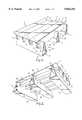
- FIG. 1represents a perspective view, obliquely from above, of a pallet according to a first conceivable embodiment of the invention
- FIG. 2shows the same pallet in an oblique view from below
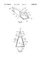
- FIG. 3represents a perspective view of a supporting member included in the pallet
- FIG. 4represents a perspective view, obliquely from above, of a pallet according to a second, preferred embodiment of the invention
- FIG. 5shows an end view of a base beam included in the pallet according to this preferred embodiment
- FIG. 6shows the same base beam towards one long side, and on a smaller scale
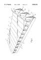
- FIG. 7represents a plan view of a blank for the manufacturing of the base beam
- FIG. 8is a side view of a deck before it has been joined to the base beams
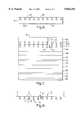
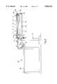
- FIG. 9is a side view of an apparatus for the manufacturing of base beams from blanks according to FIG. 7,
- FIG. 10shows, on a larger scale, the upper parts of the apparatus in the direction of the arrow X in FIG. 9, and
- FIGS. 11a-11Lis a schematic illustration of the procedure for the manufacturing of base beams.
- the pallet 1consists of the following principle parts, namely a deck 2 and a number of base beams 3, according to this embodiment three in number, which form the legs of the pallet 1.
- the materialconsists entirely of sized cardboard.
- the deck 2is manufactured from a plane sheet of sized cardboard which has been scored and folded to form a deck surface 4 consisting of a number of parallel main panels 5 and of edge panels 6 which are parallel to the main panels.
- a suitable materialis non-plastic-coated cardboard which consists of several sized layers, each layer consisting of non-plastic-coated liquid cardboard, i.e. cardboard which has been extensively sized.
- the multi-layer cardboardhas a grammage of approximately 1100 g/m 2 .
- the sheet which forms the deck 2is further folded so that the underside of the deck 2 has a number of parallel, longitudinal projections 8.
- the cross-section of the projections 8has a horizontal span which increases from a position close to the deck surface 4 down towards the base 9 of the projections, which base 9 forms a lifting surface for lifting forks.
- the projections 8have a triangular shape in cross-section, with the base 9 of the triangle constituting the said lifting surface.
- the said trianglesare isosceles triangles and the two sides which are inclined upwards and inwards towards the vertex of the triangle have been designated by 10, 11.
- the main panels 5 and edge panels 6 of the deck surface 4thus adjoin one another at the vertices of the said triangles, where the two inclined sides 10, 11 of the triangle meet.
- the vertex angle V1 of the triangleis approximately 30 according to the embodiment.
- the base beams or the legs 3consist, according to the embodiment, of sized, scored and folded cardboard.
- the base beams 3have the shape of isosceles triangles with a base 15 and inclined sides 16, 17.
- the vertex angle V2is also approximately 30.
- the sides 16, 17 of the legs 3are almost three times as long as the sides 10, 11 of the deck projections 8.
- the base beams/legs 3Arranged in the base beams/legs 3 are triangular recesses 21 which, starting from the vertex 20, extend some distance down in the top portion of the base beams.
- the recesses 21have the same dimension and shape as the outer cross-section of the projections 8 on the underside of the deck 2.
- the recesses 21are arranged in the base beams 3 in a distribution corresponding to the width of the main panels 5 on the deck surface 4. In this way, the deck 2 can be joined by dovetailing with the base beams 3 by the projections 8 being pushed into the recesses 21 in the base beams.
- the triangular shape of the projections 8is maintained in this way, and at the same time the deck 2 is anchored in the base beams, by means of the dovetailing, without the use of binders or of any securing members other than the dovetailing members themselves, i.e. the projections 8 and the recesses 21.
- Spaces 23 for lifting forksare formed under the projections 8 and between the base beams/legs 3, with the lifting forks using the base 9 of the projections 8 as a lifting surface.
- stiffening members 25are introduced into the base beams 3 in the spaces under the projections 8.
- FIG. 3shows, on an enlarged scale, the appearance of such a stabilizing and stiffening member 25.
- the latteralso consists of sized cardboard and is scored and folded so that oblique triangles 26, 27 and 28 are formed alternately to the left and to the right.
- the stiffening memberis passed into the legs 3 under the projections 8 on the deck 2, so that the base 29 of the stiffening member rests against the base 15 of the base beam/leg 3, while its plane top side 30 is pressed against the base 9 of the projection 8.
- the outer sides 31 of the triangles 26 and 28bear against the inside of the side 16 of the legs 3, while the corresponding outside 32 of the triangle 27 bears against the side 17 of the legs.
- the corners 33, 34 of the triangles 26, 27, 28are pressed into the lower comers of the legs 3.
- the stiffening members 25in this way give the legs 3 a considerably better load-bearing capacity.
- Pallets 1 of the type described abovecan be joined together to form larger pallets both in the longitudinal direction of the panels 5, 6 and also in their transverse direction, i.e. in the longitudinal direction of the base beams 3.
- the pallets 1can be joined with the aid of triangular bars which are passed into the triangular projections 8 on the deck 2 and in such a way that they extend between the pallets which are thus joined.
- These triangular barspreferably consist of sized cardboard which has been folded to form triangles.
- the pallets 1can be joined by using extended stiffening members of the same basic design as the stiffening member 25, which are passed into the base beams/legs 3 in the adjacent pallets 1 which are to be joined to each other and in such a way that they extend between the pallets which are thus joined.
- FIG. 4represents an example of a so-called half pallet.
- the pallet which is shown in FIGS. 1 and 2is an example of a so-called quarter pallet.
- the same reference numbershave been used for parts which have a direct counterpart in the embodiment according to FIGS. 1-3, for which reason these members are not described in detail here, and instead reference is made to the preceding description of the first embodiment.
- the same reference numbers as beforeare used, but with an added '.
- the difference in relation to the preceding embodimentlies in the design of the stiffening or supporting members 25' in the base beams 3'.
- the stiffening members 25 in the preceding embodimentconsisted of separate units which were guided into the base beams after their production
- the supporting members 25'are integrated from the outset with the base beams 3' and represent above all an improvement in terms of production technology, logistics and costs.
- the design of a base beam 3'is shown in greater detail in FIG. 5.
- the supporting member 25'consists quite simply of an inner pipe 37 in the shape of a regular, isosceles parallel trapezium with an outer shape which corresponds with the shape of the lower part of the base beam 3'.
- the supporting member 25'consists of several inner turns of the material from which the base beam 3' is made.
- the supporting member 25'is thus formed of two inner layers 38, 39 and 40, 41, respectively, in the area of the inclined sides of the base beam, and two layers 42, 43 at the top of the supporting member 25'.
- the side-wall layers 38, 39 and 40, 41, respectively,are integral with the outer layers 44, 45 of the base beam 3' in the area of the two inclined sides 16, 17.
- the base portion 15comprises two layers, or in one area three layers 46, 47, 48.
- the top portion 49 of the base beamconsists of only one layer, namely the continuation of the two outer layers 44, 45, and forms an upper pipe or channel 50 of triangular cross-section above the supporting member 25'.
- the recesses 21 for the projections 8 on the deck 4are formed in this top portion 49.
- the layers 38, 39 and 44, and the layers 40, 41 and 45, respectively, that is to say the layers in the area of the two inclined sides 16 and 17,are connected to one another by sizing, which further strengthens the integrated beam.
- the fact that the supporting member 25' forms a lower, inner pipe 37 in the base beam 3'also allows several pallets 1' to be assembled to form larger units by means of connecting members being passed through the inner pipes 37.
- FIG. 7shows a blank 52 for the manufacturing of a base beam 3'. It consists of a rectangular sheet of cardboard which is divided, by means of a number of parallel, transverse fold lines, into a number of parallel panels 46, 38, 42 etc., which have been given the same reference numbers as the different layers in the base beam 3' and which have been explained hereinabove with reference to FIG. 5.
- the two "last" panels 44, 45which will form outer layers in the two inclined walls 16 and 17, and will form the top portion 49, are provided with a series of holes 21x and 21y, respectively, distributed along the fold line 20a which coincides with the vertex 20 of the base beam 3'.
- the shape and size of the holes 21x and 21yare such that when the beam 3' has been given its final shape and has been placed with the vertex 20 upwards, projected on a vertical centre plane through the beam, the holes 21x and 21y correspond with the outer cross-section of the projections 8.
- the holes 21x and 21ythus have the shape of triangles of height h xy , where ##EQU1## where h is the height of the projections 8, FIG. 8, and
- V2is the vertex angle of the base beam 3'.
- the base 53 of the recesses 21x and 21ycorresponds with the length of the base 9 of the projections 8, which in turn means that the vertex angle V3 of the holes 21x and 21y is somewhat less than the vertex angle V1 of the projections 8 in compliance with simple trigonometric calculations.
- the holes 21x and 21yare joined to each other via a narrow gap 54 which crosses over the fold line 20a.
- the extent hxy of the recesses 21x and 21y from the fold line 20ais less than half the width of the panels 44 and 45, more precisely about one third of the width of the panels 44 and 45.
- All the other panelsi.e. all the panels other than the two "last" panels 44, 45, are entirely devoid of holes.
- FIGS. 9 and 10show, somewhat schematically, an apparatus 60 for the production of base beams 3' from blanks 52, FIG. 7, with certain details having been omitted from the figures so that the essential features can better be seen.
- a ring 62is mounted on a stand 61 so that it can rotate about three supporting rollers 63, 64, 65 which are mounted rotatably on the stand 61.
- the ring 62has on the outside a V-belt groove 66 for a V-belt 67 which can be driven by a motor 68 via a drive wheel 69, FIG. 10, not shown in FIG. 9, for rotation of the ring 62.
- the carrier 70consists of an inner pipe 71, an outer pipe 72, a middle screw 73 and bushes 74, 75 at the ends. This arrangement permits a high bending resistance of the unit 70, at the same time as the outer pipe 72 can be rotated about the inner pipe 71.
- a pair of double-armed levers 77are mounted on the outer pipe 72, near its outer ends, in such a way that they can be rotated together with the outer pipe 72 about its central axis 78.
- a press roller 81facing towards the centre of the ring 62, is mounted rotatably between the two outer arms 79 and is arranged to be pressed in a direction in towards the centre of the ring 62 under the effect of a pneumatic cylinder 82 which is arranged as a compression spring and which acts on the other two arms 80.
- the pneumatic cylinder 82is mounted rotatably on the ring 62.
- a member 84also extends horizontally outwards from the stand 61 parallel with the carrier 70 and with the press roller 81, and it extends as far as the outer end of the roller 81.
- the member 84is referred to hereinafter as the inner core since it is intended to form a counterstay upon winding of the blank 52 into a pipe, a priori upon winding of the inner pipe 37 which is to form a stiffening member/bearing support 25'.
- the core 84has an outer contour corresponding to the inner shape of the supporting member 25'/inner pipe 37, i.e. it has the shape of an isosceles parallel trapezium.
- FIG. 9shows the core 85 in its advanced operational position, where it is connected at its front end to the inner core 84 by way of a dowel 89 which engages in a hole (not shown) in the outer end of the core 85.
- the dowel 89is supported, in a manner such that it can be moved aside, by a holder 90 at the outer end of the inner core 84 and fixes the two cores 84, 85 to each other in the operational position of the outer core 85.
- the outer core 85can be guided to and from its operational position via the ring 62 with the aid of the belt cylinder 86.
- glue gunswhich have been designated schematically by 92 in FIG. 11. These can also be moved to and fro via the ring 62 with the aid of movement members, for example a belt cylinder, in the same way as the outer core 85.
- the ring 62In the starting position, the ring 62 is in the position shown in FIG. 10, which corresponds to stage A in FIG. 11.
- the blank 52is guided by the panel 46 into a slot 93 in the inner core 84.
- the working of the apparatus 60is controlled by a microprocessor (not shown) in conjunction with sensors (not shown).
- the ring 62From the starting position shown at stage A, the ring 62 is turned clockwise, and the press roller 81 guides the blank 52 downwards by the panel 38 on the first inclined side of the core 84, stage B.
- stage Cthe first narrow panel 42 is folded in under the core 84.
- stage Dthe panel 40 is folded by the press roller 81 up against the second inclined side of the core 84.
- stage Ethe panel 47 is folded in over the core 84.
- the ring 62stops under the command of the said sensors (not shown).
- the spray pistols 92are guided in through the ring 62 by movement and carrier members (not shown).
- the spray pistols 92are advanced as far as the end of the core 84 and then back again.
- the panels 38 and 40are sprayed with glue.
- the ring 62is then rotated one turn further, stages F, G, H and I.
- the panels 39, 43, 41 and 48are folded in against the respective sides, with the material in the panels 39 and 41 being joined to the panels 38 and 40 by means of the strands of glue applied in stage E.
- the ring 62is once again stopped.
- the glue pistols 92are guided anew through the ring 62 and spray the panels 39 and 40 with glue during the return movement.
- the outer core 85is guided into position under the inner core 84 and is fixed in this position by the said dowel 89, FIG. 9.
- the remaining material, the folds 44 and 45 with the holes 21x and 21y,is then folded in, stages J and K, and fixed to the glue-coated panels 39 and 41.
- the outer core 85is withdrawn from the triangle-shaped channel 50 which is formed.
- the deck 2is also manufactured from a scored blank which is folded to give the shape which is shown in FIG. 8. Finally, this deck 2 is joined to a number of base beams 3', of which there are three in the present embodiment, by means of the triangle-shaped projections 8 being introduced into the recesses 21 in the top portion 49 of the base beam.
- the load-bearing capacity of the palletis in the first instance determined by the strength of the lower portions of the base beams 3, 3', while the top portion of the base beams in the first instance serves to fix the deck 2 to the base beams 3, 3'.
- the material making up the base beamshas therefore been concentrated in the said lower portion, the thickness of which, according to the preferred embodiment, consists of three layers and which consequently forms, together with the connecting panels 42, 43, a powerful bearing support for the projections 8 on the deck.
- a separate supporting member 25is introduced as a bearing support into the base beams.
- the shape of the base beams 3, 3' in particularcan be varied.
- the triangular cross-section of the base beamsis preferable, and it is of particular advantage for the sides of the base beams to be inclined.
- This shapewhich is advantageous from the point of view of strength, can also be achieved using base beams whose cross-section is in the shape of an isosceles parallel trapezium with inclined walls and with a narrower side directed upwards, bearing against the top side of the deck 4, and the recesses for the projections 8 also extending over such an upper side of the base beams.
- material other than cardboardcan conceivably be used for the manufacturing of the deck and base beams.
- material other than cardboardcan conceivably be used for the manufacturing of the deck and base beams.
- the deck and base beamsusing plastic sheets, expediently comprising recycled plastic, with the fold lines being formed by means of grooves in the plastic sheets.
- the various layers in the base beamscan be fixed to one another by heat sealing, for example.
- the method for producing the pallet and in particular the base beamscan also be varied. For example, instead of winding the blank around stationary cores, it is possible to rotate the cores around a central axis, pulling on an otherwise stationary blank.
Landscapes
- Engineering & Computer Science (AREA)
- Mechanical Engineering (AREA)
- Pallets (AREA)
- Auxiliary Devices For And Details Of Packaging Control (AREA)
- Eyeglasses (AREA)
- Adornments (AREA)
- Stacking Of Articles And Auxiliary Devices (AREA)
- Making Paper Articles (AREA)
Abstract
Description
Claims (27)
Applications Claiming Priority (3)
| Application Number | Priority Date | Filing Date | Title |
|---|---|---|---|
| SE9403530 | 1994-10-17 | ||
| SE9403530ASE503535C2 (en) | 1994-10-17 | 1994-10-17 | Cargo pallet made up of base beams and a cargo deck joined to the base beams |
| PCT/SE1995/001089WO1996011852A1 (en) | 1994-10-17 | 1995-09-25 | Pallet, method for the manufacturing of the pallet, blank for a member included in the pallet, and apparatus for its manufacturing |
Publications (1)
| Publication Number | Publication Date |
|---|---|
| US5836254Atrue US5836254A (en) | 1998-11-17 |
Family
ID=20395632
Family Applications (1)
| Application Number | Title | Priority Date | Filing Date |
|---|---|---|---|
| US08/817,088Expired - LifetimeUS5836254A (en) | 1994-10-17 | 1995-09-25 | Pallet and method for the manufacturing of the pallet |
Country Status (16)
| Country | Link |
|---|---|
| US (1) | US5836254A (en) |
| EP (1) | EP0787098B1 (en) |
| JP (1) | JP3554565B2 (en) |
| KR (1) | KR100346332B1 (en) |
| CN (1) | CN1059634C (en) |
| AT (1) | ATE205151T1 (en) |
| AU (1) | AU691350B2 (en) |
| CA (1) | CA2202040C (en) |
| DE (1) | DE69522575T2 (en) |
| DK (1) | DK0787098T3 (en) |
| ES (1) | ES2161301T3 (en) |
| FI (1) | FI119595B (en) |
| NO (1) | NO321653B1 (en) |
| RU (1) | RU2129973C1 (en) |
| SE (1) | SE503535C2 (en) |
| WO (1) | WO1996011852A1 (en) |
Cited By (21)
| Publication number | Priority date | Publication date | Assignee | Title |
|---|---|---|---|---|
| US6041719A (en)* | 1997-02-03 | 2000-03-28 | Vidal; Antione | Material handling pallet |
| EP1099640A1 (en)* | 1999-11-10 | 2001-05-16 | Munksjö Förpackningar Ab | Pallet box container for goods |
| US6578814B2 (en)* | 2001-04-05 | 2003-06-17 | Surevoid Products, Inc. | Concrete flat work form |
| US20040040223A1 (en)* | 2000-08-31 | 2004-03-04 | De La Marche Peter William | Modular buildings |
| US6895722B1 (en)* | 2001-08-20 | 2005-05-24 | Icosa Village, Inc. | Folding structural panel unit |
| US6913434B1 (en)* | 1998-07-07 | 2005-07-05 | Valmet Panelboard Oy | Apparatus for handling bundles of boards and a support bed for use in such an apparatus |
| US6944928B1 (en)* | 1999-10-15 | 2005-09-20 | Olv-Pallen Aktiebolag | Process and apparatus for producing a pallet from folded material |
| US20060144734A1 (en)* | 2002-10-23 | 2006-07-06 | Baker Gerald L | Bulk bag and rigid fork lift tine receiving member combination |
| US20060175218A1 (en)* | 2005-02-07 | 2006-08-10 | Mctavish Gordon | Bulk bag handling assembly |
| US20080179320A1 (en)* | 2006-08-01 | 2008-07-31 | Patrick Abel | Paper based product packaging assembly |
| US20090020663A1 (en)* | 2005-03-18 | 2009-01-22 | Robert Booth | Support device |
| US20110168766A1 (en)* | 2009-12-03 | 2011-07-14 | Erdie Jason S | Triangular shipping container with polygonal inner support |
| US20120064279A1 (en)* | 2010-09-14 | 2012-03-15 | North Carolina Agricultural And Technical State University | Folded sheets of material for use as a structural member and assembly thereof |
| USD659938S1 (en) | 2006-05-09 | 2012-05-15 | Lsi-Lift Systems Incorporated | Tubular pallet member |
| US20150191274A1 (en)* | 2014-01-09 | 2015-07-09 | Oria Collapsibles, Llc | Pallet construction line and assembly |
| US20150282609A1 (en)* | 2014-04-02 | 2015-10-08 | Zachary Rotholz | Corrugated Furniture Design and Construction System |
| US9327868B1 (en)* | 2014-03-20 | 2016-05-03 | Michael Marquis | Pallet system for cable-enabled loading |
| US9468298B2 (en) | 2014-02-12 | 2016-10-18 | Matthew E Gerstle | Recycled corrugated child's chair |
| US9523187B2 (en) | 2016-04-26 | 2016-12-20 | Caterpillar Inc. | Decking assembly |
| WO2019109165A1 (en)* | 2017-12-08 | 2019-06-13 | Corruven Canada Inc. | Foldable sheet, structure, and pallet |
| WO2022269443A1 (en)* | 2021-06-21 | 2022-12-29 | Voorhees Michael | Load-bearing furniture from folded material |
Families Citing this family (7)
| Publication number | Priority date | Publication date | Assignee | Title |
|---|---|---|---|---|
| RU2238892C2 (en)* | 2002-02-18 | 2004-10-27 | Открытое акционерное общество "ИСПАТ КАРМЕТ" | Tray |
| KR20040043820A (en)* | 2002-11-20 | 2004-05-27 | 코러패드코리아 주식회사 | Method for folding corrugate papers for storage of articles |
| MY136925A (en)* | 2005-07-07 | 2008-11-28 | Chew Leong Chiow | Pallet with foldable platform surface |
| WO2011125071A1 (en)* | 2010-04-08 | 2011-10-13 | Ashok Syal | A pallet for carrying load |
| DE102018116352B4 (en)* | 2018-07-05 | 2021-02-25 | Dy-Pack Verpackungen Gustav Dyckerhoff Gmbh | Cardboard or paper pallet |
| PH12022550082A1 (en)* | 2019-07-12 | 2023-04-12 | Rdp Group Ltd | A shipping pallet and/or deck useful for such |
| DE202019106013U1 (en) | 2019-10-29 | 2019-11-19 | Phil Lawrence | transport packaging |
Citations (10)
| Publication number | Priority date | Publication date | Assignee | Title |
|---|---|---|---|---|
| US2951669A (en)* | 1957-04-17 | 1960-09-06 | Davidson Louis | Folding industrial pallet |
| US3131656A (en)* | 1963-12-20 | 1964-05-05 | Rene C Houle | Pallet |
| US3683822A (en)* | 1970-04-08 | 1972-08-15 | Joe R Roberts | Disposable pallet |
| SE354459B (en)* | 1970-12-08 | 1973-03-12 | R Taylor | |
| US4759295A (en)* | 1981-08-21 | 1988-07-26 | Nilsen Morten N | Freight pallet |
| US4867074A (en)* | 1989-03-10 | 1989-09-19 | Corpal Systems, Inc. | Corrugated construction pallet |
| US5184558A (en)* | 1991-11-27 | 1993-02-09 | Gaylord Container Corporation | Pallet and method and apparatus for making same |
| US5207631A (en)* | 1991-06-26 | 1993-05-04 | Fabmation, Inc. | Method and apparatus for folding of sheet material |
| US5487345A (en)* | 1989-03-09 | 1996-01-30 | Unipal International Corporation | Parametrically wrapped pallet member and pallet constructed thereof |
| US5490465A (en)* | 1993-12-27 | 1996-02-13 | Buckeye Boxes, Inc. | Paperboard/corrugated board pallets and methods for manufacturing such pallets |
Family Cites Families (1)
| Publication number | Priority date | Publication date | Assignee | Title |
|---|---|---|---|---|
| SE450482B (en)* | 1986-01-24 | 1987-06-29 | Fred Atterby | LOAD STALL CONSISTING OF BASIC PARTS AND CROSSING ROWS |
- 1994
- 1994-10-17SESE9403530Apatent/SE503535C2/enunknown
- 1995
- 1995-09-25JPJP51313896Apatent/JP3554565B2/ennot_activeExpired - Fee Related
- 1995-09-25WOPCT/SE1995/001089patent/WO1996011852A1/enactiveIP Right Grant
- 1995-09-25EPEP95935629Apatent/EP0787098B1/ennot_activeExpired - Lifetime
- 1995-09-25DKDK95935629Tpatent/DK0787098T3/enactive
- 1995-09-25CNCN95195711Apatent/CN1059634C/ennot_activeExpired - Fee Related
- 1995-09-25RURU97107858Apatent/RU2129973C1/ennot_activeIP Right Cessation
- 1995-09-25DEDE69522575Tpatent/DE69522575T2/ennot_activeExpired - Lifetime
- 1995-09-25ATAT95935629Tpatent/ATE205151T1/ennot_activeIP Right Cessation
- 1995-09-25USUS08/817,088patent/US5836254A/ennot_activeExpired - Lifetime
- 1995-09-25AUAU37573/95Apatent/AU691350B2/ennot_activeCeased
- 1995-09-25KRKR1019970702508Apatent/KR100346332B1/ennot_activeExpired - Fee Related
- 1995-09-25CACA002202040Apatent/CA2202040C/ennot_activeExpired - Fee Related
- 1995-09-25ESES95935629Tpatent/ES2161301T3/ennot_activeExpired - Lifetime
- 1997
- 1997-03-26FIFI971289Apatent/FI119595B/ennot_activeIP Right Cessation
- 1997-04-03NONO19971499Apatent/NO321653B1/ennot_activeIP Right Cessation
Patent Citations (10)
| Publication number | Priority date | Publication date | Assignee | Title |
|---|---|---|---|---|
| US2951669A (en)* | 1957-04-17 | 1960-09-06 | Davidson Louis | Folding industrial pallet |
| US3131656A (en)* | 1963-12-20 | 1964-05-05 | Rene C Houle | Pallet |
| US3683822A (en)* | 1970-04-08 | 1972-08-15 | Joe R Roberts | Disposable pallet |
| SE354459B (en)* | 1970-12-08 | 1973-03-12 | R Taylor | |
| US4759295A (en)* | 1981-08-21 | 1988-07-26 | Nilsen Morten N | Freight pallet |
| US5487345A (en)* | 1989-03-09 | 1996-01-30 | Unipal International Corporation | Parametrically wrapped pallet member and pallet constructed thereof |
| US4867074A (en)* | 1989-03-10 | 1989-09-19 | Corpal Systems, Inc. | Corrugated construction pallet |
| US5207631A (en)* | 1991-06-26 | 1993-05-04 | Fabmation, Inc. | Method and apparatus for folding of sheet material |
| US5184558A (en)* | 1991-11-27 | 1993-02-09 | Gaylord Container Corporation | Pallet and method and apparatus for making same |
| US5490465A (en)* | 1993-12-27 | 1996-02-13 | Buckeye Boxes, Inc. | Paperboard/corrugated board pallets and methods for manufacturing such pallets |
Cited By (34)
| Publication number | Priority date | Publication date | Assignee | Title |
|---|---|---|---|---|
| US6041719A (en)* | 1997-02-03 | 2000-03-28 | Vidal; Antione | Material handling pallet |
| US6913434B1 (en)* | 1998-07-07 | 2005-07-05 | Valmet Panelboard Oy | Apparatus for handling bundles of boards and a support bed for use in such an apparatus |
| US6944928B1 (en)* | 1999-10-15 | 2005-09-20 | Olv-Pallen Aktiebolag | Process and apparatus for producing a pallet from folded material |
| EP1099640A1 (en)* | 1999-11-10 | 2001-05-16 | Munksjö Förpackningar Ab | Pallet box container for goods |
| US20060130422A1 (en)* | 2000-08-03 | 2006-06-22 | De La Marche Peter W | Modular buildings |
| US7673422B2 (en) | 2000-08-31 | 2010-03-09 | Peter William De La Marche | Modular buildings |
| US20040040223A1 (en)* | 2000-08-31 | 2004-03-04 | De La Marche Peter William | Modular buildings |
| US6578814B2 (en)* | 2001-04-05 | 2003-06-17 | Surevoid Products, Inc. | Concrete flat work form |
| US6895722B1 (en)* | 2001-08-20 | 2005-05-24 | Icosa Village, Inc. | Folding structural panel unit |
| US20060144734A1 (en)* | 2002-10-23 | 2006-07-06 | Baker Gerald L | Bulk bag and rigid fork lift tine receiving member combination |
| US7594579B2 (en) | 2002-10-23 | 2009-09-29 | Gerald Lynn Baker | Bulk bag and rigid fork lift tine receiving member combination |
| US20060175218A1 (en)* | 2005-02-07 | 2006-08-10 | Mctavish Gordon | Bulk bag handling assembly |
| US8033726B2 (en) | 2005-02-07 | 2011-10-11 | LSI—Lift Systems Incorporated | Bulk bag handling assembly |
| US20090020663A1 (en)* | 2005-03-18 | 2009-01-22 | Robert Booth | Support device |
| US8322664B2 (en)* | 2005-03-18 | 2012-12-04 | Bridgeshire Packaging Limited | Support device |
| USD659938S1 (en) | 2006-05-09 | 2012-05-15 | Lsi-Lift Systems Incorporated | Tubular pallet member |
| US20080179320A1 (en)* | 2006-08-01 | 2008-07-31 | Patrick Abel | Paper based product packaging assembly |
| US20110168766A1 (en)* | 2009-12-03 | 2011-07-14 | Erdie Jason S | Triangular shipping container with polygonal inner support |
| US8459190B2 (en) | 2009-12-03 | 2013-06-11 | Jason S. Erdie | Triangular shipping container with polygonal inner support |
| US20120064279A1 (en)* | 2010-09-14 | 2012-03-15 | North Carolina Agricultural And Technical State University | Folded sheets of material for use as a structural member and assembly thereof |
| US9185984B2 (en)* | 2010-09-14 | 2015-11-17 | North Carolina Agricultural And Technical State University | Folded sheets of material for use as a structural member and assembly thereof |
| US20150191274A1 (en)* | 2014-01-09 | 2015-07-09 | Oria Collapsibles, Llc | Pallet construction line and assembly |
| US9919834B2 (en)* | 2014-01-09 | 2018-03-20 | Oria Collapsibles, Llc | Pallet construction line and assembly |
| US9468298B2 (en) | 2014-02-12 | 2016-10-18 | Matthew E Gerstle | Recycled corrugated child's chair |
| US9327868B1 (en)* | 2014-03-20 | 2016-05-03 | Michael Marquis | Pallet system for cable-enabled loading |
| US9840349B2 (en) | 2014-03-20 | 2017-12-12 | M2 Concepts And Design Llc | Pallet system for cable-enabled loading |
| US9701090B2 (en)* | 2014-04-02 | 2017-07-11 | Zachary Rotholz | Corrugated furniture design and construction system |
| US20150282609A1 (en)* | 2014-04-02 | 2015-10-08 | Zachary Rotholz | Corrugated Furniture Design and Construction System |
| US9975307B2 (en) | 2014-04-02 | 2018-05-22 | Zachary Rotholz | Corrugated furniture design and construction system |
| US9523187B2 (en) | 2016-04-26 | 2016-12-20 | Caterpillar Inc. | Decking assembly |
| WO2019109165A1 (en)* | 2017-12-08 | 2019-06-13 | Corruven Canada Inc. | Foldable sheet, structure, and pallet |
| WO2022269443A1 (en)* | 2021-06-21 | 2022-12-29 | Voorhees Michael | Load-bearing furniture from folded material |
| US20240285071A1 (en)* | 2021-06-21 | 2024-08-29 | Michael Voorhees | Load-Bearing Furniture from Folded Material |
| US12383058B2 (en)* | 2021-06-21 | 2025-08-12 | Michael Voorhees | Load-bearing furniture from folded material |
Also Published As
| Publication number | Publication date |
|---|---|
| CA2202040A1 (en) | 1996-04-25 |
| ES2161301T3 (en) | 2001-12-01 |
| FI971289A7 (en) | 1997-06-10 |
| CN1059634C (en) | 2000-12-20 |
| ATE205151T1 (en) | 2001-09-15 |
| CN1161025A (en) | 1997-10-01 |
| DE69522575T2 (en) | 2002-07-11 |
| SE9403530L (en) | 1996-04-18 |
| WO1996011852A1 (en) | 1996-04-25 |
| NO321653B1 (en) | 2006-06-19 |
| FI119595B (en) | 2009-01-15 |
| DE69522575D1 (en) | 2001-10-11 |
| NO971499L (en) | 1997-05-21 |
| EP0787098B1 (en) | 2001-09-05 |
| DK0787098T3 (en) | 2001-10-01 |
| KR100346332B1 (en) | 2002-09-18 |
| AU691350B2 (en) | 1998-05-14 |
| HK1001969A1 (en) | 1998-07-24 |
| JPH10507151A (en) | 1998-07-14 |
| CA2202040C (en) | 2006-09-19 |
| SE9403530D0 (en) | 1994-10-17 |
| FI971289A0 (en) | 1997-03-26 |
| AU3757395A (en) | 1996-05-06 |
| SE503535C2 (en) | 1996-07-01 |
| RU2129973C1 (en) | 1999-05-10 |
| EP0787098A1 (en) | 1997-08-06 |
| JP3554565B2 (en) | 2004-08-18 |
| NO971499D0 (en) | 1997-04-03 |
Similar Documents
| Publication | Publication Date | Title |
|---|---|---|
| US5836254A (en) | Pallet and method for the manufacturing of the pallet | |
| RU2443610C2 (en) | Method of fabricating multilayer container and articles thus produced | |
| US2928638A (en) | Portable pallet and method of fabricating it | |
| US5011071A (en) | Carton | |
| FI67325B (en) | SKIVELEMENTKOMBINATION MED EN LINJAER VIDVINKELFALS | |
| AU585696B2 (en) | Pallet comprising base members and crosswise members or tubes perpendicularly thereto | |
| EP0598540A1 (en) | Paper Pallet | |
| US4905864A (en) | Fibreboard sheet and blank and method for producing same | |
| US8092360B2 (en) | Methods for creating multi-walled containers | |
| US5490465A (en) | Paperboard/corrugated board pallets and methods for manufacturing such pallets | |
| JPH09503724A (en) | Structural member and articles and methods made therefrom | |
| US5448956A (en) | One-way lightweight pallet | |
| US4015544A (en) | Disposable pallet | |
| FI61994C (en) | HALVFABRIKAT FOER LIKKISTA SAMT DAERAV GJORD KISTA | |
| US9919834B2 (en) | Pallet construction line and assembly | |
| WO1995025672A1 (en) | Load support system and method and machine for the production thereof | |
| EP0738225B1 (en) | Pallet of wound corrugated paperboard | |
| GB2397568A (en) | Load handling apparatus in the form of a pallet made from a single blank | |
| AU649178B2 (en) | One-way lightweight pallet | |
| WO2025032118A1 (en) | Paperboard pallet and apparatus for producing such a pallet | |
| TWM664488U (en) | Corrugated board and pallet | |
| CA2119591A1 (en) | Recyclable paperboard pallet and method of fabrication | |
| AU2640100A (en) | Cardboard pallett |
Legal Events
| Date | Code | Title | Description |
|---|---|---|---|
| AS | Assignment | Owner name:FELLINGSBRO KARTONG AKTIEBOLAG, SWEDEN Free format text:ASSIGNMENT OF ASSIGNORS INTEREST;ASSIGNOR:JOHANSSON, SIXTEN;REEL/FRAME:008676/0992 Effective date:19970312 | |
| FEPP | Fee payment procedure | Free format text:PAYOR NUMBER ASSIGNED (ORIGINAL EVENT CODE: ASPN); ENTITY STATUS OF PATENT OWNER: SMALL ENTITY | |
| AS | Assignment | Owner name:OLV PALLEN AKTIEBOLAG, SWEDEN Free format text:ASSIGNMENT OF ASSIGNORS INTEREST;ASSIGNOR:AKTIEBOLAG, FELLINGSBRO KARTONG;REEL/FRAME:009272/0947 Effective date:19980526 | |
| STCF | Information on status: patent grant | Free format text:PATENTED CASE | |
| FPAY | Fee payment | Year of fee payment:4 | |
| FEPP | Fee payment procedure | Free format text:PAYER NUMBER DE-ASSIGNED (ORIGINAL EVENT CODE: RMPN); ENTITY STATUS OF PATENT OWNER: SMALL ENTITY Free format text:PAYOR NUMBER ASSIGNED (ORIGINAL EVENT CODE: ASPN); ENTITY STATUS OF PATENT OWNER: SMALL ENTITY | |
| FPAY | Fee payment | Year of fee payment:8 | |
| FPAY | Fee payment | Year of fee payment:12 | |
| AS | Assignment | Owner name:EQPACK AB, SWEDEN Free format text:ASSIGNMENT OF ASSIGNORS INTEREST;ASSIGNOR:OLV PALLEN AKTIEBOLAG;REEL/FRAME:026733/0707 Effective date:20110617 |