US5835267A - Radiometric calibration device and method - Google Patents
Radiometric calibration device and methodDownload PDFInfo
- Publication number
- US5835267A US5835267AUS08/893,943US89394397AUS5835267AUS 5835267 AUS5835267 AUS 5835267AUS 89394397 AUS89394397 AUS 89394397AUS 5835267 AUS5835267 AUS 5835267A
- Authority
- US
- United States
- Prior art keywords
- flux
- diffuser
- pupil
- optical system
- imaging
- Prior art date
- Legal status (The legal status is an assumption and is not a legal conclusion. Google has not performed a legal analysis and makes no representation as to the accuracy of the status listed.)
- Expired - Lifetime
Links
Images

Classifications
- G—PHYSICS
- G01—MEASURING; TESTING
- G01J—MEASUREMENT OF INTENSITY, VELOCITY, SPECTRAL CONTENT, POLARISATION, PHASE OR PULSE CHARACTERISTICS OF INFRARED, VISIBLE OR ULTRAVIOLET LIGHT; COLORIMETRY; RADIATION PYROMETRY
- G01J1/00—Photometry, e.g. photographic exposure meter
- G01J1/02—Details
- G01J1/08—Arrangements of light sources specially adapted for photometry standard sources, also using luminescent or radioactive material
- G—PHYSICS
- G01—MEASURING; TESTING
- G01J—MEASUREMENT OF INTENSITY, VELOCITY, SPECTRAL CONTENT, POLARISATION, PHASE OR PULSE CHARACTERISTICS OF INFRARED, VISIBLE OR ULTRAVIOLET LIGHT; COLORIMETRY; RADIATION PYROMETRY
- G01J1/00—Photometry, e.g. photographic exposure meter
- G01J1/02—Details
- G01J1/04—Optical or mechanical part supplementary adjustable parts
- G01J1/0407—Optical elements not provided otherwise, e.g. manifolds, windows, holograms, gratings
- G01J1/0422—Optical elements not provided otherwise, e.g. manifolds, windows, holograms, gratings using light concentrators, collectors or condensers
- G—PHYSICS
- G01—MEASURING; TESTING
- G01J—MEASUREMENT OF INTENSITY, VELOCITY, SPECTRAL CONTENT, POLARISATION, PHASE OR PULSE CHARACTERISTICS OF INFRARED, VISIBLE OR ULTRAVIOLET LIGHT; COLORIMETRY; RADIATION PYROMETRY
- G01J1/00—Photometry, e.g. photographic exposure meter
- G01J1/02—Details
- G01J1/04—Optical or mechanical part supplementary adjustable parts
- G01J1/0407—Optical elements not provided otherwise, e.g. manifolds, windows, holograms, gratings
- G01J1/0437—Optical elements not provided otherwise, e.g. manifolds, windows, holograms, gratings using masks, aperture plates, spatial light modulators, spatial filters, e.g. reflective filters
- G—PHYSICS
- G01—MEASURING; TESTING
- G01J—MEASUREMENT OF INTENSITY, VELOCITY, SPECTRAL CONTENT, POLARISATION, PHASE OR PULSE CHARACTERISTICS OF INFRARED, VISIBLE OR ULTRAVIOLET LIGHT; COLORIMETRY; RADIATION PYROMETRY
- G01J1/00—Photometry, e.g. photographic exposure meter
- G01J1/02—Details
- G01J1/04—Optical or mechanical part supplementary adjustable parts
- G01J1/0407—Optical elements not provided otherwise, e.g. manifolds, windows, holograms, gratings
- G01J1/044—Optical elements not provided otherwise, e.g. manifolds, windows, holograms, gratings using shutters
- G—PHYSICS
- G01—MEASURING; TESTING
- G01J—MEASUREMENT OF INTENSITY, VELOCITY, SPECTRAL CONTENT, POLARISATION, PHASE OR PULSE CHARACTERISTICS OF INFRARED, VISIBLE OR ULTRAVIOLET LIGHT; COLORIMETRY; RADIATION PYROMETRY
- G01J1/00—Photometry, e.g. photographic exposure meter
- G01J1/02—Details
- G01J1/04—Optical or mechanical part supplementary adjustable parts
- G01J1/0407—Optical elements not provided otherwise, e.g. manifolds, windows, holograms, gratings
- G01J1/0474—Diffusers
- G—PHYSICS
- G01—MEASURING; TESTING
- G01J—MEASUREMENT OF INTENSITY, VELOCITY, SPECTRAL CONTENT, POLARISATION, PHASE OR PULSE CHARACTERISTICS OF INFRARED, VISIBLE OR ULTRAVIOLET LIGHT; COLORIMETRY; RADIATION PYROMETRY
- G01J5/00—Radiation pyrometry, e.g. infrared or optical thermometry
- G01J5/52—Radiation pyrometry, e.g. infrared or optical thermometry using comparison with reference sources, e.g. disappearing-filament pyrometer
- G01J5/53—Reference sources, e.g. standard lamps; Black bodies
Definitions
- This inventionrelates generally to the field of radiometry, and in particular to radiometric calibration of photodetectors in space employing the sun as a deterministic source of radiation.
- Planetary imagersare useful for remote sensing of atmospheric composition, geologic morphology and chemistry, crop assessment, weather prediction, and monitoring the activities of man.
- Monochromatic and multispectral satellite based imagerscan quantify properties of the above earth characteristics, provided their solid state detector arrays are properly calibrated in relation to radiometric responsivities.
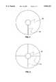
- FIG. 2A prior art method of sensor calibration employing the sun as a specular calibration light source is schematically illustrated in FIG. 2.
- This methoduses a radiometric calibration assembly 10, shown located within an earth imaging system 12, comprising primary mirror 14 and secondary mirror 16.
- Calibration assembly 10comprises an entrance port 18, a flat fold mirror 20, a lens 22, and a perforated plate 24.
- the perforated plate 24is shown in detail in FIG.
- a plurality of small apertures 26, 28, 30, 32are formed in the otherwise opaque plate 24. Each aperture is of a different size, but each is necessarily smaller than the image 34 of the sun 36 formed by lens 22 (see FIG. 2).
- the sun's imageis caused to move to, and park upon each aperture in turn.
- the fold mirror 20can be steered to place a solar image 34 (see FIG. 3) upon smallest aperture 26, resulting in a discrete lowest calibration flux level being delivered to an imaging sensor array 38.
- the array responsivity to this flux levelis measured and then fold mirror 20 can be steered to place the solar image 34 upon the next larger aperture 28, resulting in a discrete higher calibration flux level.
- the array responsivity to a sequence of discrete and increasing flux levels, representative of the range of anticipated imaging flux levelsis thus achieved.
- This prior art calibration methodretains a number of detractors. It requires very accurate pointing of the calibration device toward the sun, so that the solar image centers upon each of the circular apertures. A pointing accuracy requirement of 18 arc seconds, representing 1% of the diameter of the solar disc is typical. Even more stringent requirements are common, depending on the required calibration accuracy.
- a second detractoris that in order to match the flux passing through the apertures to the desired levels, a relatively large optical pupil of the earth imaging system must be accessed. This optical pupil is typically the primary mirror 14 of the earth imaging system 12, or the image of the primary mirror formed by the secondary mirror 16. In the first case, the pupil is partially obstructed, blocking light from entering the imager which would otherwise be available for imaging.
- the calibration assemblyis located in the vicinity of the secondary mirror, adding undesirable moment of inertia to the earth imaging system 12, and thus compromising its agility to point at targets of interest.
- a third detractoris that the two described locations of traditional calibration devices are forward of the primary mirror 14 of the earth imaging system 12. This subjects the calibration optics to the harsh environment of outer space experienced by orbiting imaging satellites.
- a fourth detractoris that the specular calibration optics result in undesirable non-uniformities in the calibration flux distribution at the imaging sensor array 38, due to the extremely high focal ratio needed to match direct solar flux levels to in-use imaging flux levels, causing even the smallest dust motes or blemishes on optical surfaces to project starkly onto the detector. This non-uniformity artifact is commonly referred to as "ripple”.
- a fifth detractoris the relatively heavy weight of prior art calibration optical assemblies.
- apparatus and method for radiometrically calibrating an imaging sensor array using the sun as a calibration light source in an optical system of the type having an accessible real conjugate of the entrance pupilincludes a flux concentrator for concentrating the sunlight.
- a flux modulatormodulates the intensity of the concentrated sunlight and flux relay optics direct the intensity modulated sunlight to the real conjugate of the entrance pupil of the optical system.
- a flux diffuser located at the real conjugate of the entrance pupil of the optical systemilluminates the imaging sensor array with diffuse intensity modulated sunlight for calibrating the imaging sensor.
- the flux concentratoris non-imaging.
- the nature of the non-imaging concentratorallows dramatic relaxation of the required pointing accuracy toward the sun. The only requirement is that the flux entering the concentrator entrance port is efficiently piped to its exit port. A typical pointing accuracy requirement is 3 arc-minutes.
- pupil obscuration and moment of inertiain the most typical case, where the earth imaging system comprises primary and secondary mirrors, the conjugate pupil location will have a non-illuminated "dead zone" at its center, due to the shadow of the secondary mirror cast upon the pupil. The optical diffuser used for calibration is positioned within this "dead zone", thus preventing any added obscuration of the available light for imaging.
- this conjugate pupilis most typically located behind the primary mirror, thus minimizing the moment of inertia added to the earth imaging system by the radiometric calibration assembly.
- the harsh environment of outer spaceis shielded from the radiometric calibration assembly because it is located behind the primary mirror and within the earth imaging system shroud.
- a significant advantage of the new radiometric calibration assemblyis its desensitization to "ripple" effects. This is because the optical diffuser feeds the imaging detector at a relatively low focal ratio, and also evades all but the final elements of the imaging optics, substantially reducing the signatures of dust, and blemishes.
- the weight of the proposed radiometric calibration assemblycan be relatively low because the non-imaging solar flux concentrator is small and may be hollow, the relay lens is small and the diffuser is very small compared with prior art specular calibration assemblies.
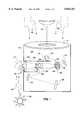
- FIG. 1is a schematic diagram of an earth imaging system employing a radiometric calibration assembly according to the present invention
- FIG. 2is a schematic representation of an earth imaging system employing a prior art device for radiometric calibration using a plate comprising a plurality of perforations;
- FIG. 3is a schematic representation showing a face-on view of the perforated plate employed in the device of FIG. 2, comprising a plurality of perforations;
- FIG. 4is a schematic diagram showing an alternative method of mounting the diffuser employed in FIG. 1;
- FIG. 5is a schematic diagram showing a further alternative method of mounting the diffuser employed in FIG. 1.
- a typical earth imaging system 12is located above the surface of the earth and pointed generally earthward, to collect information.
- Relay optics 42are configured to provide an accessible conjugate entrance pupil 44.
- the imaging sensor array 38converts the image into electrical signals that can be broadcast to earth and evaluated. This is the common mode of operation of modem earth imaging systems, including those born by aircraft and satellites.
- the calibrationinvolves determining the response of each part of the array to various accurately-known light flux levels. With this knowledge, the information generated by images of the earth can be quantitatively related to the scene being evaluated.
- a radiometric calibration assembly 10is incorporated into the interior 46 of the earth imaging system 12.
- the use of the calibration assembly 10can most easily be described by reference to the calibration flux from the sun 36, as it enters the calibration assembly 10 and is ultimately delivered to the imaging sensor array 38.
- Light 40 from earthis first prevented from entering the earth imaging system 12. This is accomplished by blocking the entrance with a shutter or door, or, in the case of an earth orbiting satellite, pointing the system away from the earth toward the darkness of deep space.
- Solar calibration flux 48emanating from the direction of the sun 36, is allowed to enter an entrance port 50 of non-imaging solar flux concentrator 52. This is accomplished by either orienting the earth imaging system 12 bodily to point the entrance port generally toward the sun, or equivalently diverting the solar flux into the entrance port 50 with an auxiliary flat fold mirror 54 shown in phantom in FIG. 1.
- Solar flux concentrator 52is preferably a tapered light pipe constructed from quartz or clear plastic. Alternatively the flux concentrator may by a hollow light pipe having internal reflective surface to save weight.
- a concentrating light pipeis a non-imaging optical element that trades off angular dispersion of the light for flux concentration.
- a specular, imaging flux concentratorsuch as a Galilean telescope may be employed.
- the solar fluxis transported from the exterior to the interior 46 of the earth imaging system 12 by passing along the length of the non-imaging solar flux concentrator 52 and emerging from an exit port 56.
- the flux levelis amplified by a factor determined by the relative areas of the entrance and exit ports 50 and 56, respectively.
- the amount of flux needed at the exit portis determined by the illumination needed at the imaging sensor 38 to match the highest intensity expected during normal imaging.
- the fluxthen encounters spatial flux modulator 58.
- spatial flux modulatorsare available and well known.
- One preferred typecomprises clear and opaque regions on a rotatable quartz substrate. As the substrate is indexed into position by a motor or solenoid (not shown), the edge of the opaque region blocks a portion of the flux, thus controlling the amount of flux passed.
- a second type of flux modulatorcomprises a graded neutral density optical transmission filter on a rotatable quartz substrate. In this case, rotation of the substrate causes regions of greater attenuation to encounter the flux, controlling the amount passed. In this way, the flux is adjusted in a deterministic fashion covering the full range from the minimum to the maximum desired calibration levels.
- the fluxnext encounters relay lens 60, which images the exit port 56 upon an optical diffuser 62.
- the lens focal length, diameter and locationare selected to assure that the spot of illumination defined by the flux is sharply defined, uniform and smaller than the diameter of diffuser 62.
- the material of diffuser 62is selected to reflect the calibration flux efficiently for all spectral wavelengths used in imagery.
- a good choice of materialis silicon dioxide powder in a clear adhesive carrier, such as Kodak white reflectance coating, most commonly used to coat the interiors of optical integrating spheres.
- the diffuser 62is preferably applied to a clear quartz substrate 66, positioned at a conjugate pupil 44 of earth imaging system 12. This pupil 44 is most commonly identified as the image of the primary mirror 14, formed by the secondary mirror 16 and other down-stream imaging optical elements 42. These additional elements 42 may be mirrors, which place a sharp image of the scene upon the imaging sensor array 38. A consequence of their use is the existence of accessible conjugate pupil 44.
- the conjugate pupil 44For two reasons. The first reason is that the imaging light appears to come from the pupil. It is therefore the ideal location for the optical diffuser 62, which should reflect the calibration flux from the same position and direction as the imaging light. The second reason is that there naturally exists a partially obstructed region 64, which is the shadow of the secondary mirror 16 projected into the pupil by the imaging system optical elements. This is pertinent, because it provides a region of the pupil from which no imaging light emanates. This region is therefore freely available for our optical diffuser 62, without resulting in any blockage of imaging light by the diffuser 62. Therefore we have the diffuser 62 ideally located for its intended function, without in any way detracting from the full available illumination and resolution of the imaging optics. Finally, the calibration flux is reflected from the diffuser 62 and falls on the imaging sensor array 38. The deterministic solar calibration flux is thus provided to effect an accurate calibration of the array 38.
- spatial flux modulator 58is indexed to a multiplicity of positions, causing a corresponding deterministic sequence of calibration flux levels to excite the array 38.
- the electrical signals from the arrayare either collected and analyzed by an on-board computer to effect calibration of the array, or alternatively down-linked via radio signals to the ground for calibration analysis.
- differences in responsivity bias and gaincan be corrected, to allow the array to perform in a more ideal sense when imaging. This will cause hard copy images of the ground scene to be free of blemishes and other irregularities that would otherwise contaminate the raw images.
- quantitative evaluation of the image information for scientific purposeswill have greater integrity, accuracy and utility.
- the earth imaging system 12can take on a variety of forms other than that described. It may be populated with lenses rather than mirrors. Lenses are more typical of imagers of smaller sizes up to 10 cm clear aperture. Mirrors are more typical of imagers of larger sizes ranging from 10 cm to many meters.
- remote calibrationusing the sun as a source. This is most typically a need when calibrating unmanned imagers such as those resident on satellites and drones.
- Other imaging systemscan also use the described calibration hardware and methodology. For example, lunar based astronomical observatories and earth imagers would greatly benefit.
- Planetary imaging satelliteswould also benefit, as well as earth-orbiting astronomical observatories.
- the non-imaging solar flux concentrator 52was described as preferred for solar flux collection and transfer from the outside to the inside of the earth imaging system 12.
- An alternative collection devicecould be a combination of mirrors or lenses, providing a periscope transport of solar flux.
- Two types of spatial light modulators 58were described. Many others are well known in the art, including liquid crystal modulators, electrically excited dye cells and moire convolution screens.
- Relay lens 60could alternatively be in the form of a concave mirror.
- the optical diffuser 62is described as reflective. It could alternatively be a transmissive diffuser, such as fire-flashed opal glass.
- the supporting structure for the diffuseris described as a clear quartz substrate 66. Other materials such as glass may be used. Alternatively, a rod 68 as shown in FIG. 4, or wires 70 as shown in FIG. 5 could be used to support a small disc comprising the diffuser 62.
Landscapes
- Physics & Mathematics (AREA)
- General Physics & Mathematics (AREA)
- Spectroscopy & Molecular Physics (AREA)
- Photometry And Measurement Of Optical Pulse Characteristics (AREA)
Abstract
Description
Claims (40)
Priority Applications (1)
| Application Number | Priority Date | Filing Date | Title |
|---|---|---|---|
| US08/893,943US5835267A (en) | 1997-07-15 | 1997-07-15 | Radiometric calibration device and method |
Applications Claiming Priority (1)
| Application Number | Priority Date | Filing Date | Title |
|---|---|---|---|
| US08/893,943US5835267A (en) | 1997-07-15 | 1997-07-15 | Radiometric calibration device and method |
Publications (1)
| Publication Number | Publication Date |
|---|---|
| US5835267Atrue US5835267A (en) | 1998-11-10 |
Family
ID=25402382
Family Applications (1)
| Application Number | Title | Priority Date | Filing Date |
|---|---|---|---|
| US08/893,943Expired - LifetimeUS5835267A (en) | 1997-07-15 | 1997-07-15 | Radiometric calibration device and method |
Country Status (1)
| Country | Link |
|---|---|
| US (1) | US5835267A (en) |
Cited By (35)
| Publication number | Priority date | Publication date | Assignee | Title |
|---|---|---|---|---|
| US20060132763A1 (en)* | 1998-06-26 | 2006-06-22 | Hagler Thomas W | Method and apparatus for radiation analysis and encoder |
| US7166825B1 (en) | 2005-05-17 | 2007-01-23 | Itt Manufacturing Enterprises, Inc. | Solar calibration device and method |
| US7482572B1 (en) | 2005-07-25 | 2009-01-27 | Itt Manufacturing Enterprises, Inc. | Transmissive diffuser with a layer of polytetrafluoroethylene on the output surface for use with an on-orbit radiometric calibration |
| US20100032557A1 (en)* | 2007-02-09 | 2010-02-11 | Raytheon Company | Specular array for radiometric calibration and method |
| US8067738B1 (en) | 2009-08-25 | 2011-11-29 | Ball Aerospace & Technologies Corp. | Space based calibration transfer spectroradiometer |
| CN102879094A (en)* | 2012-09-28 | 2013-01-16 | 北京航空航天大学 | Impact analysis method of imaging spectrometer radiometric calibration precision on data quality |
| US20130222606A1 (en)* | 2012-02-28 | 2013-08-29 | Lytro, Inc. | Compensating for variation in microlens position during light-field image processing |
| US9420276B2 (en) | 2012-02-28 | 2016-08-16 | Lytro, Inc. | Calibration of light-field camera geometry via robust fitting |
| US10205896B2 (en) | 2015-07-24 | 2019-02-12 | Google Llc | Automatic lens flare detection and correction for light-field images |
| US10275898B1 (en) | 2015-04-15 | 2019-04-30 | Google Llc | Wedge-based light-field video capture |
| US10275892B2 (en) | 2016-06-09 | 2019-04-30 | Google Llc | Multi-view scene segmentation and propagation |
| US10298834B2 (en) | 2006-12-01 | 2019-05-21 | Google Llc | Video refocusing |
| US10334151B2 (en) | 2013-04-22 | 2019-06-25 | Google Llc | Phase detection autofocus using subaperture images |
| US10341632B2 (en) | 2015-04-15 | 2019-07-02 | Google Llc. | Spatial random access enabled video system with a three-dimensional viewing volume |
| US10354399B2 (en) | 2017-05-25 | 2019-07-16 | Google Llc | Multi-view back-projection to a light-field |
| US10412373B2 (en) | 2015-04-15 | 2019-09-10 | Google Llc | Image capture for virtual reality displays |
| US10419737B2 (en) | 2015-04-15 | 2019-09-17 | Google Llc | Data structures and delivery methods for expediting virtual reality playback |
| US10440407B2 (en) | 2017-05-09 | 2019-10-08 | Google Llc | Adaptive control for immersive experience delivery |
| US10444931B2 (en) | 2017-05-09 | 2019-10-15 | Google Llc | Vantage generation and interactive playback |
| US10469873B2 (en) | 2015-04-15 | 2019-11-05 | Google Llc | Encoding and decoding virtual reality video |
| US10474227B2 (en) | 2017-05-09 | 2019-11-12 | Google Llc | Generation of virtual reality with 6 degrees of freedom from limited viewer data |
| US10540818B2 (en) | 2015-04-15 | 2020-01-21 | Google Llc | Stereo image generation and interactive playback |
| US10546424B2 (en) | 2015-04-15 | 2020-01-28 | Google Llc | Layered content delivery for virtual and augmented reality experiences |
| US10545215B2 (en) | 2017-09-13 | 2020-01-28 | Google Llc | 4D camera tracking and optical stabilization |
| US10552947B2 (en) | 2012-06-26 | 2020-02-04 | Google Llc | Depth-based image blurring |
| US10567464B2 (en) | 2015-04-15 | 2020-02-18 | Google Llc | Video compression with adaptive view-dependent lighting removal |
| US10565734B2 (en) | 2015-04-15 | 2020-02-18 | Google Llc | Video capture, processing, calibration, computational fiber artifact removal, and light-field pipeline |
| US10594945B2 (en) | 2017-04-03 | 2020-03-17 | Google Llc | Generating dolly zoom effect using light field image data |
| US10679361B2 (en) | 2016-12-05 | 2020-06-09 | Google Llc | Multi-view rotoscope contour propagation |
| CN112284533A (en)* | 2019-07-24 | 2021-01-29 | 中国科学院上海技术物理研究所启东光电遥感中心 | Radiometer for remote sensor on-orbit atmospheric correction |
| US10965862B2 (en) | 2018-01-18 | 2021-03-30 | Google Llc | Multi-camera navigation interface |
| US20210383573A1 (en)* | 2020-06-03 | 2021-12-09 | Labsphere, Inc. | Calibration network systems and methods of using the same |
| US11297255B1 (en) | 2020-09-18 | 2022-04-05 | Raytheon Company | On-board light source calibration |
| US11328446B2 (en) | 2015-04-15 | 2022-05-10 | Google Llc | Combining light-field data with active depth data for depth map generation |
| US11822033B2 (en) | 2019-12-16 | 2023-11-21 | Halliburton Energy Services, Inc. | Radiometric modeling for optical identification of sample materials |
Citations (7)
| Publication number | Priority date | Publication date | Assignee | Title |
|---|---|---|---|---|
| US3922085A (en)* | 1974-08-22 | 1975-11-25 | Tamarack Scient Co Inc | Illuminator for microphotography |
| US3957354A (en)* | 1975-02-03 | 1976-05-18 | Rca Corporation | Diffractive subtractive color filtering technique |
| US4496222A (en)* | 1981-12-21 | 1985-01-29 | Texas Instruments Incorporated | Apparatus and method for photolithography with phase conjugate optics |
| US4623245A (en)* | 1985-02-21 | 1986-11-18 | The United States Of America As Represented By The Secretary Of The Air Force | System of white-light density pseudocolor encoding with three primary colors |
| US5291333A (en)* | 1992-07-01 | 1994-03-01 | The United States Of America As Represented By The Secretary Of The Air Force | Alignment system for a segmented telescope |
| US5345340A (en)* | 1993-05-20 | 1994-09-06 | The United States Of America As Represented By The Secretary Of The Army | Plural pass vision system |
| US5406412A (en)* | 1993-06-17 | 1995-04-11 | Visidyne, Inc. | High-resolution synthetic aperture adaptive optics system |
- 1997
- 1997-07-15USUS08/893,943patent/US5835267A/ennot_activeExpired - Lifetime
Patent Citations (7)
| Publication number | Priority date | Publication date | Assignee | Title |
|---|---|---|---|---|
| US3922085A (en)* | 1974-08-22 | 1975-11-25 | Tamarack Scient Co Inc | Illuminator for microphotography |
| US3957354A (en)* | 1975-02-03 | 1976-05-18 | Rca Corporation | Diffractive subtractive color filtering technique |
| US4496222A (en)* | 1981-12-21 | 1985-01-29 | Texas Instruments Incorporated | Apparatus and method for photolithography with phase conjugate optics |
| US4623245A (en)* | 1985-02-21 | 1986-11-18 | The United States Of America As Represented By The Secretary Of The Air Force | System of white-light density pseudocolor encoding with three primary colors |
| US5291333A (en)* | 1992-07-01 | 1994-03-01 | The United States Of America As Represented By The Secretary Of The Air Force | Alignment system for a segmented telescope |
| US5345340A (en)* | 1993-05-20 | 1994-09-06 | The United States Of America As Represented By The Secretary Of The Army | Plural pass vision system |
| US5406412A (en)* | 1993-06-17 | 1995-04-11 | Visidyne, Inc. | High-resolution synthetic aperture adaptive optics system |
Cited By (42)
| Publication number | Priority date | Publication date | Assignee | Title |
|---|---|---|---|---|
| US20060132763A1 (en)* | 1998-06-26 | 2006-06-22 | Hagler Thomas W | Method and apparatus for radiation analysis and encoder |
| US7330253B2 (en)* | 1998-06-26 | 2008-02-12 | Aspectrics, Inc. | Method and apparatus for radiation analysis and encoder |
| US7166825B1 (en) | 2005-05-17 | 2007-01-23 | Itt Manufacturing Enterprises, Inc. | Solar calibration device and method |
| US7482572B1 (en) | 2005-07-25 | 2009-01-27 | Itt Manufacturing Enterprises, Inc. | Transmissive diffuser with a layer of polytetrafluoroethylene on the output surface for use with an on-orbit radiometric calibration |
| US10298834B2 (en) | 2006-12-01 | 2019-05-21 | Google Llc | Video refocusing |
| US20100032557A1 (en)* | 2007-02-09 | 2010-02-11 | Raytheon Company | Specular array for radiometric calibration and method |
| WO2008100693A3 (en)* | 2007-02-09 | 2011-06-30 | Raytheon Company | Specular array for radiometric calibration and method |
| US8158929B2 (en) | 2007-02-09 | 2012-04-17 | Raytheon Company | Specular array for radiometric calibration and method |
| US8067738B1 (en) | 2009-08-25 | 2011-11-29 | Ball Aerospace & Technologies Corp. | Space based calibration transfer spectroradiometer |
| US20130222606A1 (en)* | 2012-02-28 | 2013-08-29 | Lytro, Inc. | Compensating for variation in microlens position during light-field image processing |
| US8831377B2 (en)* | 2012-02-28 | 2014-09-09 | Lytro, Inc. | Compensating for variation in microlens position during light-field image processing |
| US9420276B2 (en) | 2012-02-28 | 2016-08-16 | Lytro, Inc. | Calibration of light-field camera geometry via robust fitting |
| US9172853B2 (en) | 2012-02-28 | 2015-10-27 | Lytro, Inc. | Microlens array architecture for avoiding ghosting in projected images |
| US10552947B2 (en) | 2012-06-26 | 2020-02-04 | Google Llc | Depth-based image blurring |
| CN102879094B (en)* | 2012-09-28 | 2014-12-31 | 北京航空航天大学 | Impact analysis method of imaging spectrometer radiometric calibration precision on data quality |
| CN102879094A (en)* | 2012-09-28 | 2013-01-16 | 北京航空航天大学 | Impact analysis method of imaging spectrometer radiometric calibration precision on data quality |
| US10334151B2 (en) | 2013-04-22 | 2019-06-25 | Google Llc | Phase detection autofocus using subaperture images |
| US10546424B2 (en) | 2015-04-15 | 2020-01-28 | Google Llc | Layered content delivery for virtual and augmented reality experiences |
| US10540818B2 (en) | 2015-04-15 | 2020-01-21 | Google Llc | Stereo image generation and interactive playback |
| US10341632B2 (en) | 2015-04-15 | 2019-07-02 | Google Llc. | Spatial random access enabled video system with a three-dimensional viewing volume |
| US11328446B2 (en) | 2015-04-15 | 2022-05-10 | Google Llc | Combining light-field data with active depth data for depth map generation |
| US10412373B2 (en) | 2015-04-15 | 2019-09-10 | Google Llc | Image capture for virtual reality displays |
| US10419737B2 (en) | 2015-04-15 | 2019-09-17 | Google Llc | Data structures and delivery methods for expediting virtual reality playback |
| US10275898B1 (en) | 2015-04-15 | 2019-04-30 | Google Llc | Wedge-based light-field video capture |
| US10565734B2 (en) | 2015-04-15 | 2020-02-18 | Google Llc | Video capture, processing, calibration, computational fiber artifact removal, and light-field pipeline |
| US10469873B2 (en) | 2015-04-15 | 2019-11-05 | Google Llc | Encoding and decoding virtual reality video |
| US10567464B2 (en) | 2015-04-15 | 2020-02-18 | Google Llc | Video compression with adaptive view-dependent lighting removal |
| US10205896B2 (en) | 2015-07-24 | 2019-02-12 | Google Llc | Automatic lens flare detection and correction for light-field images |
| US10275892B2 (en) | 2016-06-09 | 2019-04-30 | Google Llc | Multi-view scene segmentation and propagation |
| US10679361B2 (en) | 2016-12-05 | 2020-06-09 | Google Llc | Multi-view rotoscope contour propagation |
| US10594945B2 (en) | 2017-04-03 | 2020-03-17 | Google Llc | Generating dolly zoom effect using light field image data |
| US10444931B2 (en) | 2017-05-09 | 2019-10-15 | Google Llc | Vantage generation and interactive playback |
| US10474227B2 (en) | 2017-05-09 | 2019-11-12 | Google Llc | Generation of virtual reality with 6 degrees of freedom from limited viewer data |
| US10440407B2 (en) | 2017-05-09 | 2019-10-08 | Google Llc | Adaptive control for immersive experience delivery |
| US10354399B2 (en) | 2017-05-25 | 2019-07-16 | Google Llc | Multi-view back-projection to a light-field |
| US10545215B2 (en) | 2017-09-13 | 2020-01-28 | Google Llc | 4D camera tracking and optical stabilization |
| US10965862B2 (en) | 2018-01-18 | 2021-03-30 | Google Llc | Multi-camera navigation interface |
| CN112284533A (en)* | 2019-07-24 | 2021-01-29 | 中国科学院上海技术物理研究所启东光电遥感中心 | Radiometer for remote sensor on-orbit atmospheric correction |
| US11822033B2 (en) | 2019-12-16 | 2023-11-21 | Halliburton Energy Services, Inc. | Radiometric modeling for optical identification of sample materials |
| US20210383573A1 (en)* | 2020-06-03 | 2021-12-09 | Labsphere, Inc. | Calibration network systems and methods of using the same |
| US12125246B2 (en)* | 2020-06-03 | 2024-10-22 | Labsphere, Inc. | Calibration network systems and methods of using the same |
| US11297255B1 (en) | 2020-09-18 | 2022-04-05 | Raytheon Company | On-board light source calibration |
Similar Documents
| Publication | Publication Date | Title |
|---|---|---|
| US5835267A (en) | Radiometric calibration device and method | |
| Baumgardner et al. | Monochromatic imaging instrumentation for applications in aeronomy of the Earth and planets | |
| Aminou et al. | Characteristics of the Meteosat Second Generation (MSG) radiometer/imager: SEVIRI | |
| Thome et al. | Reflectance-and irradiance-based calibration of Landsat-5 Thematic Mapper | |
| US8174693B1 (en) | Calibration optic for a solar/earth spectrometer | |
| Carbary et al. | Ultraviolet and visible imaging and spectrographic imaging instrument | |
| Shields et al. | Daylight visible/NIR whole-sky imagers for cloud and radiance monitoring in support of UV research programs | |
| Feister et al. | Ground-based cloud images and sky radiances in the visible and near infrared region from whole sky imager measurements | |
| Slater et al. | Unified approach to pre-and in-flight satellite-sensor absolute radiometric calibration | |
| Thatte et al. | SINFONI: a near-infrared AO-assisted integral field spectrometer for the VLT | |
| GB2318699A (en) | Multiple CCD array imaging system | |
| Giovane et al. | The solar occultation technique for remote sensing of particulates in the Earth's atmosphere: 2. Skylab results of a 48‐km aerosol layer | |
| Morgan et al. | Calibration of the New Horizons long-range reconnaissance imager | |
| Folkman et al. | Updated results from performance characterization and calibration of the TRWIS III Hyperspectral Imager | |
| Mueller et al. | Gerb: An Earth radiation budget instrument on second generation Meteosat | |
| Lobb | Design of a spectrometer system for measurements on earth atmosphere from geostationary orbit | |
| Bezy et al. | Medium-resolution imaging spectrometer (MERIS) | |
| Ishiguro et al. | Development of a zodiacal light observation system: WIZARD | |
| Waddell et al. | Evaluation Of The RCA 640 X1024 Charge-Coupled-Device Imager For Astronomical Use | |
| Rafert et al. | Hyperspectral observations of space objects | |
| Markham et al. | Radiometric Calibration of the Landsat-7 Enhanced Thematic Mapper Plus | |
| Frank et al. | Search for atmospheric holes with the Viking cameras | |
| Bruegge et al. | MISR instrument development and test status | |
| Schwehm et al. | Recent developments in space-borne zodiacal light photometry | |
| Rork | Ground-Based Electro-Optical Technology Development |
Legal Events
| Date | Code | Title | Description |
|---|---|---|---|
| AS | Assignment | Owner name:EASTMAN KODAK COMPANY, NEW YORK Free format text:ASSIGNMENT OF ASSIGNORS INTEREST;ASSIGNORS:MASON, KENNETH L.;DEY, THOMAS W.;REEL/FRAME:008702/0805 Effective date:19970715 | |
| FEPP | Fee payment procedure | Free format text:PAYOR NUMBER ASSIGNED (ORIGINAL EVENT CODE: ASPN); ENTITY STATUS OF PATENT OWNER: LARGE ENTITY | |
| STCF | Information on status: patent grant | Free format text:PATENTED CASE | |
| FPAY | Fee payment | Year of fee payment:4 | |
| AS | Assignment | Owner name:ITT MANUFACTURING ENTERPRISES, INC., DELAWARE Free format text:ASSIGNMENT OF ASSIGNORS INTEREST;ASSIGNOR:EASTMAN KODAK COMPANY;REEL/FRAME:015980/0844 Effective date:20040916 | |
| FPAY | Fee payment | Year of fee payment:8 | |
| FPAY | Fee payment | Year of fee payment:12 | |
| AS | Assignment | Owner name:EXELIS, INC., VIRGINIA Free format text:ASSIGNMENT OF ASSIGNORS INTEREST;ASSIGNOR:ITT MANUFACTURING ENTERPRISES, LLC (FORMERLY KNOWN AS ITT MANUFACTUING ENTERPRISES, INC.);REEL/FRAME:027994/0195 Effective date:20111028 | |
| AS | Assignment | Owner name:HARRIS CORPORATION, FLORIDA Free format text:MERGER;ASSIGNOR:EXELIS INC.;REEL/FRAME:039362/0534 Effective date:20151223 |