US5835128A - Wireless redistribution of television signals in a multiple dwelling unit - Google Patents
Wireless redistribution of television signals in a multiple dwelling unitDownload PDFInfo
- Publication number
- US5835128A US5835128AUS08/757,881US75788196AUS5835128AUS 5835128 AUS5835128 AUS 5835128AUS 75788196 AUS75788196 AUS 75788196AUS 5835128 AUS5835128 AUS 5835128A
- Authority
- US
- United States
- Prior art keywords
- television signal
- frequency range
- translated
- television
- signal
- Prior art date
- Legal status (The legal status is an assumption and is not a legal conclusion. Google has not performed a legal analysis and makes no representation as to the accuracy of the status listed.)
- Expired - Lifetime
Links
Images


Classifications
- H—ELECTRICITY
- H04—ELECTRIC COMMUNICATION TECHNIQUE
- H04H—BROADCAST COMMUNICATION
- H04H40/00—Arrangements specially adapted for receiving broadcast information
- H04H40/18—Arrangements characterised by circuits or components specially adapted for receiving
- H04H40/27—Arrangements characterised by circuits or components specially adapted for receiving specially adapted for broadcast systems covered by groups H04H20/53 - H04H20/95
- H04H40/90—Arrangements characterised by circuits or components specially adapted for receiving specially adapted for broadcast systems covered by groups H04H20/53 - H04H20/95 specially adapted for satellite broadcast receiving
- H—ELECTRICITY
- H04—ELECTRIC COMMUNICATION TECHNIQUE
- H04N—PICTORIAL COMMUNICATION, e.g. TELEVISION
- H04N7/00—Television systems
- H04N7/20—Adaptations for transmission via a GHz frequency band, e.g. via satellite
Definitions
- the present inventionrelates generally to television signal distribution systems and, more particularly, to wireless television signal redistribution systems for distributing television signals received from a satellite or other signal source to a plurality of individual receiving units within one or more multiple dwelling units.
- Cable-based television systemstransmit one or more individual television signals or "channels" over wire, while free-space propagation systems transmit one or more channels over-the-air, i.e., in a wireless manner.
- Most large-scale cable and wireless television signal distribution systemsbroadcast a broadband television signal having a plurality of individual television signals or channels modulated onto one or more carrier frequencies within a discernable frequency band.
- Some wireless television signal distribution systemsuse one or more geosynchronous satellites to broadcast a broadband television signal to receiving units within a large geographic area, while other wireless systems are land-based, using one or more transmitters located within smaller geographic areas to broadcast to individual receiver units within those geographic areas.
- An example of a land-based "cellular" type television signal distribution systemis disclosed in Bossard, U.S. Pat. No. 4,747,160. This system includes multiple television signal transmitting stations, each of which transmits a television signal to individual receivers spread throughout a limited geographic region, and is configured so that adjacent transmitting stations use modulation and frequency diversity to prevent interference.
- Some cellular systemssuch as those commonly referred to as LMDS (local multi-point distribution system) and MMDS (multi-channel, multi-point distribution system), use a land-based cellular-type transmitting setup to rebroadcast satellite signals at frequencies different than the frequencies used by the satellite.
- LMDSlocal multi-point distribution system
- MMDSmulti-channel, multi-point distribution system
- Each of the transmitters of an LMDS systemtypically transmits within a one to five mile radius cell while each of the transmitters of an MMDS system typically transmits within an approximately 30-mile radius cell.
- Satellite television signal distribution systemsgenerally include an earth station that compiles a number of individual television signals or channels into a broadband television signal, modulates a carrier frequency band with the broadband television signal and then transmits (uplinks) the modulated television signal to a geosynchronous satellite.
- the satelliteamplifies the received television signal, shifts the television signal to a different carrier frequency band and transmits (downlinks) the frequency shifted television signal to earth for reception at individual receiving units.
- the uplink and downlink broadband television signals of satellite systemsare typically divided into a plurality of transponder signals, each having a plurality of individual channels.
- Satellite systemsmay also broadcast a set of transponder signals at multiple polarizations, for example, a right-hand circular polarization (RHCP) and a left-hand circular polarization (LHCP), within the band of carrier frequencies associated with the satellite; effectively doubling the number of channels broadcast by the system.
- RHCPright-hand circular polarization
- LHCPleft-hand circular polarization
- Satellite television signal distribution systemsexist for many frequency bands, including the so-called "Ku-band” which ranges from approximately 12 GHz to 18 GHz.
- the digital satellite system (DSS®) developed by DirecTV®uses an uplink signal having 16 RHCP transponder signals and 16 LHCP transponder signals modulated into the frequency band between about 17.2 GHz and about 17.7 GHz.
- Each of these 32 transponder signalsis programmed-multiplexed to include data packets associated with anywhere from about five to eight individual television channels and is modulated according to a quadrature phase shift keying (QSPK) modulation scheme.
- QSPKquadrature phase shift keying
- the satellites associated with the DSS® systemshift the uplink transponder signals to carrier frequencies ranging from approximately 12.2 GHz to approximately 12.7 GHz and transmit these frequency-shifted transponder signals back to earth for reception at each of a plurality of individual receiver units.
- a receiving antennatypically comprising a parabolic dish antenna, is pointed in the general direction of the transmitting satellite (or other transmitting location) to thereby receive the broadband television signal.
- such antennasinclude a low noise block (LNB) which filters and shifts the incoming signal to an intermediate frequency band, such as L-band which is between approximately 1.0 GHz and approximately 2.0 GHz.
- LNBlow noise block
- the DSS® systemin particular, shifts the signal received from the satellite to the frequency band between about 950 MHz and about 1450 MHz.
- both the RHCP and the LHCP transponder signalsare shifted down to L-band and provided, via separate lines, to a set-top box or an integrated receiver and detector (IRD) associated with the receiver unit.
- IRDintegrated receiver and detector
- an audio-visual program associated with a particular channel within one of the program-multiplexed transponder signals at L-bandis decoded and is provided to a television for display on a television screen.
- the receiving antennas or dishes associated with land-based or satellite-based wireless television signal distribution systemsare typically large and cumbersome.
- C-band satellite dishesare generally in the range of four to five feet in diameter and, therefore, require a large amount of operating space.
- MDUmultiple dwelling unit
- MDUmultiple dwelling unit
- Even if a single dish antenna is used to provide satellite signals to all of the receiving units within an MDU, common L-band multi-user distribution solutions typically used to support such a systemare fraught with installment and maintenance problems.
- the present inventionrelates to a system for redistributing a television signal, such as a broadband television signal, to a multiplicity of receiver units within one or more MDU's.
- a receiving antennareceives a broadband television signal from, for example, a satellite or a land-based transmitter.
- a mixertranslates the broadband television signal into a different carrier frequency band and delivers the translated signal to one or more broadcasting antennas located at advantageous sites within the MDU.
- the broadcasting antennastransmit the translated signal along, for example, one or more outside walls of the MDU to be received by antennas associated with each of the individual receiver units within the MDU.
- the receiver unitsthen demodulate the received broadband signal and provide user-specified channels to television sets for display.
- a television signal redistribution systemfor redistributing a modulated television signal to a plurality of individual receivers at a local site includes a main receiver disposed at the local site to receive the modulated television signal and circuitry for translating the modulated television signal from a first frequency range to a second frequency range.
- the systemalso includes one or more transmitters that broadcast the frequency-translated television signal over-the-air for reception by a multiplicity of receiver units at the local site.
- the translation circuitrymay shift the modulated television signal to a third frequency range and then distribute this shifted signal to the one or more transmitters which, in turn, translate the shifted signal to the second frequency range. Different ones of the transmitters may translate the shifted signal to different portions of the second frequency range which, preferably, is near the 60 GHz band.
- the systemmay also include a device which inserts a further signal, such as a voice, digital or television signal into the frequency-translated television signal before transmitting the frequency-translated television signal to individual receiver units.
- a further signalsuch as a voice, digital or television signal
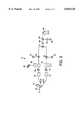
- FIG. 1is a diagram illustrating the wireless redistribution system of the present invention as installed on two adjacent MDU's;
- FIG. 2is a block diagram of a main television signal receiver and wireless rebroadcasting unit according to the present invention
- FIG. 3is a block diagram of an individual receiver unit according to the present invention.
- FIG. 4is a block diagram of a repeater transmitter illustrated in FIG. 1.
- the television signal rebroadcasting system of the present inventionwill be described herein as being used with a satellite-based, DSS® system having a broadband television signal modulated onto a carrier frequency band centered around approximately 12.45 GHz. It is understood however, that the television signal rebroadcasting system of the present invention can be used with any other type of satellite or land-based wireless television distribution system (such as MMDS, LMDS, C-band, microwave, etc.) or, for that matter, with any cable-based television signal broadcasting system, including those which transmit broadband as well as narrowband television signals.
- any other type of satellite or land-based wireless television distribution systemsuch as MMDS, LMDS, C-band, microwave, etc.
- any cable-based television signal broadcasting systemincluding those which transmit broadband as well as narrowband television signals.
- a local siteis considered to be any geographic area of relatively small proportion, for example, on the size of a city block or less, containing one or more buildings or structures capable of having a plurality of individual receiving units therein.
- Each of the MDU's 10 and 12may be any type of multiple dwelling unit including, for example, an apartment, townhome, or condominium complex, a hotel/motel, a multi-use building and/or any other type of building or structure in which multiple television signal receivers may be located.
- the television signal rebroadcasting unit associated with the MDU 10includes a main television signal receiver and wireless rebroadcasting unit 13 disposed on the roof of the MDU 10.
- the television signal receiver 13includes a main receiving antenna 14, in the form of a parabolic dish antenna, pointed towards, for example, a satellite that transmits the DSS® broadband modulated television signal.
- An LNB 16 associated with the dish antenna 14receives the modulated satellite signal reflected from the dish antenna, filters this signal and then mixes the filtered signal down to an intermediate frequency band, for example, the band between 950 MHz and 1450 MHz.
- the LNB 16shifts each of these components down to the intermediate frequency band.
- the LNB 16provides these shifted, intermediate frequency television signals to each of, for example, four transmitters 20, 22, 24, and 26 through one or more cable connections.
- Each of the transmitters 20, 22, 24, and 26translates or shifts the intermediate frequency television signal to a second carrier frequency band, for example, to a region within the V-band (e.g., between about 59 GHz and about 64 GHz), and provides this frequency-translated signal to one or more transmission antennas.
- the transmission antennas associated with each of the transmitters 20, 22, 24, and 26,transmit the translated signal along, for example, one or more of the walls of the MDU 10 for reception by individual receiver units within the MDU 10.
- an antenna associated with the transmitter 24may propagate the translated television signal along the front wall 30 of the MDU 10 to receiver antennas 32, 34, and 36 associated with individual receiver units within the MDU 10.
- antennas associated with the transmitters 20, 22, and 26propagate translated television signals along an exterior wall of the MDU 10 to distribute this signal to other receiver antennas.
- Each of the receiver antennassuch as the antennas 32, 34, and 36, is coupled to a receiver unit within the MDU 10.
- These receiver unitsdemodulate the received translated (V-band) television signal and strip one or more of the channels therefrom for display on a television screen, as will be described in more detail with reference to FIG. 3.
- the receiver antennas within the MDU 10are configured to receive the translated (V-band) television signal and, as such, may be placed in any convenient location within the MDU 10 that allows reception of the signal broadcast by one of the transmitting antennas 20, 22, 24 or 26. If desired, a receiver antenna may be disposed on an exterior portion of one of the walls or windows of the MDU 10 including, for example, a window sill. If the transmitters 20, 22, 24, and 26 transmit with sufficient power, a receiver antenna may be located at the interior of the MDU 10, such as on an inner surface of a wall or a window.
- each receiver antennawill be dependent upon the specific configuration of the system, including the transmitting frequency of the transmitting antennas, the position of the transmitting antennas, the power output by the transmitting antennas, the objects within a path between the transmitting and receiver antennas, the distance between the transmitting and receiver antennas, etc.
- main receiving antenna 14is illustrated in FIG. 1 as located on the roof of the MDU 10, the main receiving antenna 14 may be placed in any other desired location which allows reception of a desired satellite or other television signal.
- a main receiving antenna 40 associated with the MDU 12is illustrated in FIG. 1 as being mounted on a lamp post 41 in front of the MDU 12 because placement of this antenna on the roof of the MDU 12 would cause that antenna to be "shadowed" from the television signal source by the MDU 10.
- the main receiving antenna 40includes a two-channel LNB which mixes the broadband satellite signal centered at approximately 12.45 GHz down to L-band (i.e., from 950 MHz to 1450 MHz).
- L-bandi.e., from 950 MHz to 1450 MHz.
- the L-band signalis then provided to transmitters 42 and 44, which are also attached to the lamp post 41.
- the transmitters 42 and 44translate the broadband television signal up to, for example, a portion of the V-band range, and broadcast this translated television signal along the walls 46 and 48 of the MDU 12 for reception by individual receivers within the MDU 12.
- the MDU 12has walls 52 and 54 which are blocked or shadowed from the transmitters 20-26, 42, and 44 as well as from the satellite television signal source.
- the individual dwelling units having outside exposure only along the walls 52 and 54 of the MDU 12will not be able to receive the 11.95 GHz satellite signal or the translated (V-band) signal emitted by any of the transmitters 20-26, 42 and 44.
- a repeater transmitter 56is located on the roof of the MDU 12.
- the repeater transmitter 56includes a receiver antenna (similar to the antennas 32, 34, and 36) that receives the translated (V-band) signal from, for example, the transmitter 26.
- the repeater transmitter 56also includes a transmitting antenna which rebroadcasts the received translated (V-band) signal along the wall 52 of the MDU 12 for reception within the individual dwelling units along that wall.
- a similar repeater transmittercan be placed on the MDU 12 to provide coverage of the wall 54 and/or any other shadowed locations. In this manner, each of the individual dwelling units within the MDU's 10 and 12 can receive all of the television channels within the broadband satellite signal received by the main receiving antennas 14 and 40 without having cable or wires run thereto.
- FIG. 1illustrates each of the MDU's 10 and 12 as having a separate main receiving antenna associated therewith, it will be understood that one main receiving antenna could be used with multiple MDU's.
- the television signal rebroadcasting system disclosed hereincan be used at a local site including two or more MDU's (or other buildings) adjacent or near to each another and is not necessarily limited to use at a local site having only one building or MDU associated therewith.
- the transmitter 26may be used to propagate the translated (V-band) signal to receiver antennas on the wall 48 of the MDU 12, while the main receiving antenna 40 can be replaced with a repeater transmitter (similar to the repeater transmitter 56) positioned to receive the translated (V-band) signal from the transmitter 24 or 26 and to retransmit that signal to the individual receiver units along the wall 46.
- a repeater transmittersimilar to the repeater transmitter 56
- multiple MDU's and/or other buildingscan share the main receiving antenna and transmitters in any other desired manner.
- any MDUmay have multiple television signal rebroadcasting systems associated therewith, i.e., each MDU may have two or more local sites therein.
- an MDUwill include multiple main receiving antennas and one or more transmitters associated with each of the main receiving antennas.
- the transmitters associated with the different main receiving antennasmay mix the satellite signal up to a different region within the, for example, V-band, to provide frequency discrimination between the separate but adjacent rebroadcasting systems.
- the transmitters 42 and 44 associated with the MDU 12may transmit the translated (V-band) signal at a slightly different frequency band than the transmitters 20, 22, 24, and 26 associated with the MDU 10.
- the different transmitters associated with any one television signal redistribution systemmay transmit at a different region within, for example, the V-band frequency range, to provide frequency discrimination therebetween.
- FIG. 1illustrates four transmitting antennas associated with the MDU 14, any other number of transmitters may be placed in any desired locations on or adjacent the MDU 10 so long as these antennas are positioned to propagate the translated signal to desired locations within the MDU's 10 and 12.
- the broadband television signalhas been described as being mixed down to L-band and then back up to V-band for transmission over-the-air to the individual receiver antennas, any other desired frequencies could be used instead of the L-band and V-band frequencies.
- the television signal received at the main receiving antennacould be immediately translated to, for example, the V-band range and sent out over wire to the transmitting antennas 20-26 without the use of the intermediate L-band conversion.
- this methodis not preferred due to the poor high frequency transmission properties of cable lines.
- the V-band and particularly, the region of the V-band near 60 GHz, and, even more particularly, the frequency range from approximately 55 GHz to approximately 66 GHzis considered to be particularly useful for redistributing the incoming television signal over-the-air to individual receiver units because of the high free-space propagation losses which occur at this band.
- These losseswhich are caused in large part by the absorption effects of oxygen, essentially limit the propagation range of the translated signal to receiver units within the MDU in which the system is being used and, possibly, MDU's or other buildings adjacent or near the MDU in which the system is being used, i.e., to the receiver units at a local site.
- the V-band translated signalis not likely to interfere with other over-the-air transmission systems which avoid this frequency range specifically because of its poor free-space propagation properties.
- V-bandbetween 59 GHz and 64 GHz is also considered useful because the United States Federal Communications Commission (FCC) has indicated that it will allow unlicensed use of this band. As a result, a manufacturer or user of the rebroadcasting system using this portion of the V-band will not have to obtain a license from the FCC.
- FCCFederal Communications Commission
- While a preferred television signal rebroadcasting system for use with a DSS® satellite signalis described hereafter as using the portion of V-band extending from 59.45 GHz to 61.20 GHz, the particular band used to transmit the translated signal from the main antenna to the receiver antennas can use less than or more than this band. It is desirable, however, that at least a portion of the translated signal falls within the frequency band between about 55 GHz and about 66 GHz, where high propagation losses occur.
- the main receiving antenna 14is designed to receive a DSS® satellite signal having a RHCP modulated component and a LHCP modulated component at the frequency band between approximately 12.2 GHz and approximately 12.7 GHz.
- the signal received by the antenna 14is reflected into a receiving horn 60 and is provided to the two-channel LNB 16.
- Each of the LNB channelsfilters and then shifts one of the RHCP or the LHCP component of the received signal down to a portion of the L-band between approximately 0.95 GHz and approximately 1.45 GHz.
- a first channel of the LNB 16provides the RHCP component (shifted to L-band) through a bias tee 64 to an amplifier 66.
- the bias tee 64provides a DC signal, typically 13 volts, to the LNB 16 to power the first channel.
- the amplifier 66provides an amplified L-band signal to an insertion unit 68 which adds or inserts other signals, such as television signals, radio signals, voice signals, digital data signals, etc., to the L-band signal from the amplifier 66.
- the inserted signalsmay be delivered from, for example, an antenna 69 which receives a local television signal or from a modem, or any other receiving device.
- the insertion unit 68may comprise any known type of signal insertion device such as a two-way power divider manufactured by Channel Master (part number 2271IFD) and may modulate the inserted signals into a frequency band which is higher or lower than that associated with the RHCP component delivered by the LNB 16, for example, between approximately 1.45 GHz and approximately 1.7 GHz.
- a two-way power divider manufactured by Channel Masterpart number 2271IFD
- the insertion unit 68may comprise any known type of signal insertion device such as a two-way power divider manufactured by Channel Master (part number 2271IFD) and may modulate the inserted signals into a frequency band which is higher or lower than that associated with the RHCP component delivered by the LNB 16, for example, between approximately 1.45 GHz and approximately 1.7 GHz.
- the output of the insertion unit 68is provided to a mixer 70 which, in turn, is coupled to a local oscillator (LO) 72 that oscillates at approximately 13.0 GHz.
- the mixer 70which may be any standard mixer or frequency translation device, translates the L-band signal up to a frequency band between approximately 13.95 GHz and approximately 14.70 GHz and provides this signal to a summer 73.
- a second channel of the LNB 16provides the LHCP component at L-band through a bias tee 74 to an amplifier 76.
- the bias tee 74provides a DC signal, typically 17 volts, to the LNB 16 to power the second channel of the LNB 16.
- the amplifier 76provides an amplified L-band signal to an insertion unit 78 that adds other television, radio, etc. signals thereto in a manner similar to the insertion unit 68.
- the output of the insertion unit 78is provided to a mixer 80 that, in turn, is coupled to an LO 82 which oscillates at approximately 12.0 GHz.
- the mixer 80translates the output of the insertion unit 78 up to a frequency band between approximately 12.95 GHz and approximately 13.70 GHz and provides this signal to the summer 73.
- the summer 73adds the signals from the mixers 70 and 80 to produce a signal centered around about 13.8 GHz having the RHCP component (of the satellite television signal) at a frequency band between approximately 13.95 GHz and approximately 14.7 GHz and having the LHCP component (of the satellite television signal) at a frequency band between approximately 12.95 GHz approximately and 13.7 GHz.
- the RHCP and LHCP components of the original satellite signalare shifted in frequency with respect to one another to provide frequency discrimination between the two components.
- An amplifier 86amplifies the output of the summer 74 and provides this amplified signal to a tripler 88.
- the tripler 88uses the output of a 15.5 GHz LO 90, as amplified by an amplifier 92, to triple the frequency of the signal from the summer 73 and, thereby, produces the frequency-translated television signal.
- this translated signalis at a carrier frequency range near or around 60 GHz, e.g., going from approximately 59.45 to approximately 61.2 GHz.
- the tripler 88may comprise any known or desired device which triples the carrier frequency of a modulated signal including, for example, any known harmonic upconverter.
- the 60 GHz translated television signalis provided to a transmitting antenna 95 which, in turn, broadcasts the translated 60 GHz signal to any number of individual receiver units.
- the tripler 88may send the translated television signal to any number of transmitting antennas.
- each transmittersuch as any of the transmitters 20-26, 42, and 44, includes all of the elements illustrated in FIG. 2 except the antenna 14, the receiving horn 60, the LNB 16, and the bias tees 64 and 74 so that transmission from the main receiving antenna 14 to the transmitting antennas is performed at L-band instead of at high frequencies such as V-band.
- FIG. 2illustrates conversion up to V-band using a tripler 88 and mixers 70 and 80, it is understood that any other single or multistage translation device or mixer, such as a quadrupler, could be used instead.
- a receiving antenna(illustrated as the receiving antenna 36 of FIG. 1) is adapted to receive the frequency range transmitted by the transmitting antenna 95, e.g., between approximately 59.45 GHz and approximately 61.20 GHz, and provides the received translated television signal to a mixer 102.
- the mixer 102which is coupled to an LO 104 that oscillates at approximately 16.25 GHz, mixes the received translated 60 GHz signal down to a frequency band between approximately 10.7 GHz and approximately 12.45 GHz.
- An amplifier 106amplifies the output of the mixer 102 and provides this amplified signal to a switchable wide-band, low noise block 108, which may comprise, for example, a Ku-band/Y-band amplifier (part number 150018), manufactured by California Amplifier.
- the low noise block 108translates one of two bands of frequencies within the 12 GHz signal down to L-band, e.g., between approximately 0.95 GHz and approximately 1.45 GHz, and blocks or filters the other of the bands.
- the low noise block 108passes the signals at a first frequency band between approximately 10.7 GHz and 11.45 GHz (which correspond to the LHCP component of the signal received by the antenna 14 of FIG. 2 along with the additional signals added thereto by the insertion unit 78) or passes the signals at a second frequency band between approximately 11.7 GHz and 12.45 GHz (which correspond to the RHCP component of the signal received by the antenna 14 of FIG. 2 along with the additional signals added thereto by the insertion unit 68) and down-converts the passed band of frequencies to L-band using any known or desired technique, such as mixing.
- the low noise block 108switches between the first and second bands based upon a DC input signal delivered from an IRD or set-top box 110 through a line 112. For example, if the user wants to view a television signal that is provided on a channel within the RHCP component of the satellite television signal, the low noise block 108 switches to the second frequency band to provide the IRD 110 with the band of frequencies containing the desired television signal.
- the mixer 102, LO 104 and low noise block 108translate the received translated 60 GHz signal back to L-band so that the signal delivered to the IRD 110 appears to the IRD 110 as if it was delivered directly from the LNB 16 of the main receiving antenna 14.
- the low noise block 108provides the down-converted first or second band of signals through the line 112, through an insertion port 114, which may comprise a standard diplexer that provides a connection to a UHF/VHF antenna, and then through another line 116 to the IRD 110.
- the IRD 110demodulates the received signal, strips a particular television signal from the provided band of television signals according to the channel selected by a user and delivers this signal to a television for use in generating a display on a television screen.
- the IRD 110may be any desired type of IRD or set-top box, such as any of those associated with the DSS® system, e.g., those manufactured by Sony, Thompson, Hughes Network Systems, or RCA, or any other set-top box manufactured for the particular satellite or land-based television distribution system for which the wireless redistribution system is being used.
- the repeater transmitter 56 of FIG. 1includes a receiving antenna 120 configured and positioned to receive the V-band translated television signal generated by any of the transmitters of FIG. 1.
- the received V-band signalis provided to an amplifier 122 and then to a transmitting antenna 124 which is positioned or directed to transmit the amplified V-band signal to one or more receiver units along, for example, the wall 52 of the MDU 12.
- the amplifier 122may amplify the received translated signal at the frequency band at which this signal is transmitted, e.g., V-band, it is considered desirable to have the amplifier 122 down-convert the received translated signal to an intermediate frequency, such as Ku-band (preferably between approximately 11.7 GHz and approximately 12.2 GHz), amplify the signal at the intermediate frequency and then up-convert the signal back to, for example, V-band, for retransmission by the transmitting antenna 124.
- This conversion processavoids the use of transistors at V-band where it is very difficult to obtain commercially viable transistors.
- the received television signalcan be translated and rebroadcast to be transmitted to individual receiver units at any desired frequency other than the preferred V-band or 60 GHz band to provide for wider geographical coverage or to take advantage of any desirable reflection or transmission properties available at those other frequencies.
- the transmitting antennas described hereinare situated to propagate the translated television signal along walls (which enhances the distance these signals will propagate at the 60 GHz band), the transmitting antennas may be situated to propagate in any other desired or advantageous manner, such as using direct line-of-sight, reflection, etc.
Landscapes
- Physics & Mathematics (AREA)
- Astronomy & Astrophysics (AREA)
- General Physics & Mathematics (AREA)
- Engineering & Computer Science (AREA)
- Signal Processing (AREA)
- Multimedia (AREA)
- Radio Relay Systems (AREA)
Abstract
Description
Claims (31)
Priority Applications (1)
| Application Number | Priority Date | Filing Date | Title |
|---|---|---|---|
| US08/757,881US5835128A (en) | 1996-11-27 | 1996-11-27 | Wireless redistribution of television signals in a multiple dwelling unit |
Applications Claiming Priority (1)
| Application Number | Priority Date | Filing Date | Title |
|---|---|---|---|
| US08/757,881US5835128A (en) | 1996-11-27 | 1996-11-27 | Wireless redistribution of television signals in a multiple dwelling unit |
Publications (1)
| Publication Number | Publication Date |
|---|---|
| US5835128Atrue US5835128A (en) | 1998-11-10 |
Family
ID=25049614
Family Applications (1)
| Application Number | Title | Priority Date | Filing Date |
|---|---|---|---|
| US08/757,881Expired - LifetimeUS5835128A (en) | 1996-11-27 | 1996-11-27 | Wireless redistribution of television signals in a multiple dwelling unit |
Country Status (1)
| Country | Link |
|---|---|
| US (1) | US5835128A (en) |
Cited By (106)
| Publication number | Priority date | Publication date | Assignee | Title |
|---|---|---|---|---|
| US5970386A (en)* | 1997-01-27 | 1999-10-19 | Hughes Electronics Corporation | Transmodulated broadcast delivery system for use in multiple dwelling units |
| US6023612A (en)* | 1996-07-05 | 2000-02-08 | Thomcast Communications, Inc. | Modular transmission system and method |
| US6125261A (en)* | 1997-06-02 | 2000-09-26 | Hughes Electronics Corporation | Method and system for communicating high rate data in a satellite-based communications network |
| WO2001017188A1 (en)* | 1999-09-01 | 2001-03-08 | Sony Electronics, Inc. | Receiver system and related method |
| US20010039180A1 (en)* | 2000-05-03 | 2001-11-08 | Hughes Electronics Corporation | Communication system for rebroadcasting electronic content within local area network |
| US6377782B1 (en) | 1999-03-01 | 2002-04-23 | Mediacell, Inc. | Method and apparatus for communicating between a client device and a linear broadband network |
| US20020072357A1 (en)* | 2000-11-07 | 2002-06-13 | Jun-Ichi Matsuda | Wireless communication network and wireless communication apparatus suitable for indoor network |
| US20020094775A1 (en)* | 1995-02-22 | 2002-07-18 | Global Communications, Inc. | Satellite broadcast receiving and distribution system |
| GR1003965B (en)* | 2001-09-14 | 2002-08-06 | Χασαν Χιλμη Χατζημιλιαζημ | Trasnitter for receiving and emitting a wide spectrum fo television channels |
| US6430742B1 (en)* | 1997-08-27 | 2002-08-06 | Koninklijke Philips Electronics N.V. | Device for distributing television signals by cable |
| US6429827B1 (en)* | 1998-12-28 | 2002-08-06 | Transystem, Inc. | Integrated MMDS antenna with reflector mounted on a totally sealed single-body dipole-transceiver base |
| US20020137621A1 (en)* | 2001-01-19 | 2002-09-26 | Agency For Defense Development | Alumina-silica ceramic and producing method thereof |
| US20030036410A1 (en)* | 2001-05-14 | 2003-02-20 | Judd Mano D. | Translation unit for wireless communications system |
| US20030054763A1 (en)* | 2001-09-20 | 2003-03-20 | Judd Mano D. | Method and apparatus for band-to-band translation in a wireless communication system |
| US6581208B1 (en)* | 1999-02-19 | 2003-06-17 | Masprodenkoh Kabushikikaisha | Up-converter and down-converter for in-building CATV system |
| US6615407B1 (en)* | 1999-02-19 | 2003-09-02 | Masprodenkoh Kabushikikaisha | In-building CATV system, and up-converter and down-converter for use therein |
| US6622307B1 (en)* | 1999-03-26 | 2003-09-16 | Hughes Electronics Corporation | Multiple-room signal distribution system |
| US20030172560A1 (en)* | 2000-05-05 | 2003-09-18 | Sanjurjo Ana Dominguez | Ear tag adaptable device for taking samples to identify cattle by means of dna |
| WO2003032503A3 (en)* | 2001-10-12 | 2003-11-06 | Gen Dynamics Ots Aerospace Inc | Wireless data communication system for a vehicle |
| US6708029B2 (en) | 1997-06-02 | 2004-03-16 | Hughes Electronics Corporation | Broadband communication system for mobile users in a satellite-based network |
| US20040139477A1 (en)* | 2003-01-15 | 2004-07-15 | Russell David B. | 60 GHz RF CATV repeater |
| US20040157554A1 (en)* | 1997-06-02 | 2004-08-12 | Hughes Electronics Corporation | Broadband communication system for mobile users in a satellite-based network |
| US20040172652A1 (en)* | 2001-02-09 | 2004-09-02 | Fisk Julian Basil | Distribution and networking of television, video and other signals, installation of such distribution systems, and control of television sets |
| US6812905B2 (en)* | 1999-04-26 | 2004-11-02 | Andrew Corporation | Integrated active antenna for multi-carrier applications |
| US20040244040A1 (en)* | 2003-06-02 | 2004-12-02 | Vickers Walter Andrew | Remote cable system |
| US20050114893A1 (en)* | 2003-11-26 | 2005-05-26 | Evans Wetmore | Wi-Fi receiver system and method |
| US6906681B2 (en) | 2002-09-27 | 2005-06-14 | Andrew Corporation | Multicarrier distributed active antenna |
| US6915529B1 (en)* | 1998-02-27 | 2005-07-05 | Sharp Kabushiki Kaisha | Milliwave transmitting device, milliwave receiving device and milliwave transmission and reception system capable of simplifying wiring of a receiving system of terrestrial broadcasting service and satellite broadcasting service |
| US20050273821A1 (en)* | 2004-05-14 | 2005-12-08 | Hundley Michael R | Wireless connection system for a satellite dish and receiver |
| US6983174B2 (en) | 2002-09-18 | 2006-01-03 | Andrew Corporation | Distributed active transmit and/or receive antenna |
| US7020890B1 (en)* | 1999-04-05 | 2006-03-28 | Sharp Kabushiki Kaisha | Millimeter wave transmitter, millimeter wave receiver and millimeter wave communication system enabling simplification of wiring and improvement in degree of freedom for setting receiver in receiving system for terrestrial broadcasting and satellite broadcasting |
| US7027431B1 (en) | 1998-07-10 | 2006-04-11 | Upstate Systems Tec, Inc. | Wireless device connection in single medium wiring scheme for multiple signal distribution in building and access port therefor |
| US20060101494A1 (en)* | 2002-12-06 | 2006-05-11 | Thomson Licensing S.A. | Method and system for premium channel and pay per view video resell |
| US7047555B1 (en)* | 1999-07-23 | 2006-05-16 | Masprodenkoh Kabushikikaisha | In-building CATV system, down-converter, up-converter and amplifier |
| US20060259929A1 (en)* | 2005-04-01 | 2006-11-16 | James Thomas H | Automatic level control for incoming signals of different signal strengths |
| US7165365B1 (en)* | 2000-04-03 | 2007-01-23 | The Directv Group, Inc. | Satellite ready building and method for forming the same |
| US7184723B2 (en) | 2004-10-22 | 2007-02-27 | Parkervision, Inc. | Systems and methods for vector power amplification |
| US7197760B1 (en)* | 1998-12-11 | 2007-03-27 | Grundig Multimedia B.V. | Apparatus for selecting satellite TV channels using a channel selection unit for VHF and UHF channels |
| US20070082603A1 (en)* | 2005-10-12 | 2007-04-12 | John Norin | Triple band combining approach to satellite signal distribution |
| US20070202804A1 (en)* | 2006-02-28 | 2007-08-30 | Vrd Technologies, Inc. | Satellite signal relay and receiver |
| US7280848B2 (en) | 2002-09-30 | 2007-10-09 | Andrew Corporation | Active array antenna and system for beamforming |
| US20070250909A1 (en)* | 2005-09-02 | 2007-10-25 | The Directv Group, Inc. | Network fraud prevention via registration and verification |
| US20080022324A1 (en)* | 2006-07-19 | 2008-01-24 | Montage Technology Group, Ltd | Personal Area Television Broadcasting |
| US7355470B2 (en) | 2006-04-24 | 2008-04-08 | Parkervision, Inc. | Systems and methods of RF power transmission, modulation, and amplification, including embodiments for amplifier class transitioning |
| WO2008093927A1 (en)* | 2007-02-02 | 2008-08-07 | Kaonmedia Co., Ltd. | Mdu broadcasting signal distribution system |
| US7477871B1 (en)* | 2004-12-31 | 2009-01-13 | Entropic Communications Inc. | Signal selector and combiner system for broadband content distribution |
| US7487532B2 (en) | 2003-01-15 | 2009-02-03 | Cisco Technology, Inc. | Optimization of a full duplex wideband communications system |
| US7516470B2 (en) | 2002-08-02 | 2009-04-07 | Cisco Technology, Inc. | Locally-updated interactive program guide |
| US7522875B1 (en)* | 2004-12-31 | 2009-04-21 | Entropic Communications Inc. | Signal selector and combiner system for broadband content distribution |
| US7542715B1 (en)* | 2001-11-07 | 2009-06-02 | Entropic Communications Inc. | Signal selector and combiner for broadband content distribution |
| US7545935B2 (en) | 2002-10-04 | 2009-06-09 | Scientific-Atlanta, Inc. | Networked multimedia overlay system |
| US20090247006A1 (en)* | 2008-01-22 | 2009-10-01 | Wi3, Inc., New York | Network access point having interchangeable cartridges |
| US7600249B1 (en)* | 2005-07-13 | 2009-10-06 | Blevins Garry D | Systems and methods for service provisioning of multiple dwelling units |
| US7620129B2 (en) | 2007-01-16 | 2009-11-17 | Parkervision, Inc. | RF power transmission, modulation, and amplification, including embodiments for generating vector modulation control signals |
| US7698723B2 (en) | 2000-12-28 | 2010-04-13 | At&T Intellectual Property I, L.P. | System and method for multimedia on demand services |
| US7827581B1 (en) | 2000-02-29 | 2010-11-02 | BE Labs, Inc. | Wireless multimedia system |
| US7849486B2 (en) | 2000-11-14 | 2010-12-07 | Russ Samuel H | Networked subscriber television distribution |
| US7876998B2 (en) | 2005-10-05 | 2011-01-25 | Wall William E | DVD playback over multi-room by copying to HDD |
| US7885682B2 (en) | 2006-04-24 | 2011-02-08 | Parkervision, Inc. | Systems and methods of RF power transmission, modulation, and amplification, including architectural embodiments of same |
| US7900230B2 (en) | 2005-04-01 | 2011-03-01 | The Directv Group, Inc. | Intelligent two-way switching network |
| US20110059690A1 (en)* | 2004-05-28 | 2011-03-10 | Echostar Technologies L.L.C | Method and Device for Band Translation |
| US7908625B2 (en)* | 2002-10-02 | 2011-03-15 | Robertson Neil C | Networked multimedia system |
| US7911272B2 (en) | 2007-06-19 | 2011-03-22 | Parkervision, Inc. | Systems and methods of RF power transmission, modulation, and amplification, including blended control embodiments |
| US20110083152A1 (en)* | 2009-10-01 | 2011-04-07 | Verizon Patent And Licensing, Inc. | System and method for providing communications service to individual units of a multiple dwelling unit |
| US7945932B2 (en) | 2005-04-01 | 2011-05-17 | The Directv Group, Inc. | Narrow bandwidth signal delivery system |
| US7950038B2 (en) | 2005-04-01 | 2011-05-24 | The Directv Group, Inc. | Transponder tuning and mapping |
| US7954127B2 (en)* | 2002-09-25 | 2011-05-31 | The Directv Group, Inc. | Direct broadcast signal distribution methods |
| US7987486B2 (en) | 2005-04-01 | 2011-07-26 | The Directv Group, Inc. | System architecture for control and signal distribution on coaxial cable |
| US8013675B2 (en) | 2007-06-19 | 2011-09-06 | Parkervision, Inc. | Combiner-less multiple input single output (MISO) amplification with blended control |
| US8019275B2 (en) | 2005-10-12 | 2011-09-13 | The Directv Group, Inc. | Band upconverter approach to KA/KU signal distribution |
| US8024759B2 (en) | 2005-04-01 | 2011-09-20 | The Directv Group, Inc. | Backwards-compatible frequency translation module for satellite video delivery |
| US8031804B2 (en) | 2006-04-24 | 2011-10-04 | Parkervision, Inc. | Systems and methods of RF tower transmission, modulation, and amplification, including embodiments for compensating for waveform distortion |
| US8046806B2 (en) | 2002-10-04 | 2011-10-25 | Wall William E | Multiroom point of deployment module |
| US8094640B2 (en) | 2003-01-15 | 2012-01-10 | Robertson Neil C | Full duplex wideband communications system for a local coaxial network |
| US8127326B2 (en) | 2000-11-14 | 2012-02-28 | Claussen Paul J | Proximity detection using wireless connectivity in a communications system |
| US8229383B2 (en) | 2009-01-06 | 2012-07-24 | The Directv Group, Inc. | Frequency drift estimation for low cost outdoor unit frequency conversions and system diagnostics |
| US8238813B1 (en) | 2007-08-20 | 2012-08-07 | The Directv Group, Inc. | Computationally efficient design for broadcast satellite single wire and/or direct demod interface |
| US8295224B1 (en) | 2010-03-16 | 2012-10-23 | Deshong Rick L | Wireless signal transceiver system |
| US8315336B2 (en) | 2007-05-18 | 2012-11-20 | Parkervision, Inc. | Systems and methods of RF power transmission, modulation, and amplification, including a switching stage embodiment |
| US8334722B2 (en) | 2007-06-28 | 2012-12-18 | Parkervision, Inc. | Systems and methods of RF power transmission, modulation and amplification |
| US8549565B2 (en) | 2005-04-01 | 2013-10-01 | The Directv Group, Inc. | Power balancing signal combiner |
| US8601519B1 (en) | 2000-12-28 | 2013-12-03 | At&T Intellectual Property I, L.P. | Digital residential entertainment system |
| US8621525B2 (en) | 2005-04-01 | 2013-12-31 | The Directv Group, Inc. | Signal injection via power supply |
| US8627385B2 (en) | 2002-10-04 | 2014-01-07 | David B. Davies | Systems and methods for operating a peripheral record playback device in a networked multimedia system |
| US8677423B2 (en) | 2000-12-28 | 2014-03-18 | At&T Intellectual Property I, L. P. | Digital residential entertainment system |
| US20140096163A1 (en)* | 2012-10-03 | 2014-04-03 | Syncbak, Inc. | Providing and receiving wireless broadcasts |
| US8712318B2 (en) | 2007-05-29 | 2014-04-29 | The Directv Group, Inc. | Integrated multi-sat LNB and frequency translation module |
| US8719875B2 (en) | 2006-11-06 | 2014-05-06 | The Directv Group, Inc. | Satellite television IP bitstream generator receiving unit |
| US8755454B2 (en) | 2011-06-02 | 2014-06-17 | Parkervision, Inc. | Antenna control |
| US8789115B2 (en) | 2005-09-02 | 2014-07-22 | The Directv Group, Inc. | Frequency translation module discovery and configuration |
| US8910196B2 (en) | 2012-01-30 | 2014-12-09 | Syncbak, Inc. | Broadcast area identification and content distribution |
| US8909246B2 (en) | 2010-09-09 | 2014-12-09 | Syncbak, Inc. | Broadcast tuning concepts |
| US20150089548A1 (en)* | 2013-09-24 | 2015-03-26 | Echostar Technologies L.L.C. | Field-programmable low-noise block downconverter |
| US8997157B1 (en) | 2003-06-18 | 2015-03-31 | The Directv Group, Inc. | Audio/video satellite broadcast network |
| US9106316B2 (en) | 2005-10-24 | 2015-08-11 | Parkervision, Inc. | Systems and methods of RF power transmission, modulation, and amplification |
| US9179170B2 (en) | 2005-05-27 | 2015-11-03 | EchoStar Technologies, L.L.C. | Low noise block converter feedhorn |
| US9277271B2 (en)* | 2012-02-23 | 2016-03-01 | Zenith Electronics Llc | Wireless network antenna apparatus and method |
| US20160301474A1 (en)* | 2015-04-08 | 2016-10-13 | Corning Optical Communications LLC | Fiber-wireless system and methods for simplified and flexible fttx deployment and installation |
| US9608677B2 (en) | 2005-10-24 | 2017-03-28 | Parker Vision, Inc | Systems and methods of RF power transmission, modulation, and amplification |
| US9942618B2 (en) | 2007-10-31 | 2018-04-10 | The Directv Group, Inc. | SMATV headend using IP transport stream input and method for operating the same |
| US10278131B2 (en) | 2013-09-17 | 2019-04-30 | Parkervision, Inc. | Method, apparatus and system for rendering an information bearing function of time |
| CN110557189A (en)* | 2019-08-23 | 2019-12-10 | 北京无线电测量研究所 | v-band communication satellite transponder |
| US10530479B2 (en) | 2012-03-02 | 2020-01-07 | Corning Optical Communications LLC | Systems with optical network units (ONUs) for high bandwidth connectivity, and related components and methods |
| US10735838B2 (en) | 2016-11-14 | 2020-08-04 | Corning Optical Communications LLC | Transparent wireless bridges for optical fiber-wireless networks and related methods and systems |
| US11070873B2 (en)* | 2017-12-28 | 2021-07-20 | Dish Network L.L.C. | Locally generated spot beam replacement |
| US11082726B2 (en)* | 2017-12-28 | 2021-08-03 | Dish Network L.L.C. | Remotely generated encoding metadata for local content encoding |
Citations (22)
| Publication number | Priority date | Publication date | Assignee | Title |
|---|---|---|---|---|
| US1730412A (en)* | 1923-12-05 | 1929-10-08 | Wired Radio Inc | High-frequency broadcasting over power lines |
| US3323063A (en)* | 1964-08-07 | 1967-05-30 | Theodore Granik | System for re-diffusion of received radio signals |
| US4183054A (en)* | 1977-09-30 | 1980-01-08 | Harris Corporation | Digital, frequency-translated, plural-channel, vestigial sideband television communication system |
| JPS5647183A (en)* | 1979-09-27 | 1981-04-28 | Pioneer Electronic Corp | Picture signal transfer method of catv system |
| US4290068A (en)* | 1979-12-14 | 1981-09-15 | Bogner Richard D | Microwave television system |
| US4439784A (en)* | 1979-09-26 | 1984-03-27 | Pioneer Electronic Corporation | Power cutting device for terminal units of CATV system |
| US4545075A (en)* | 1981-11-18 | 1985-10-01 | Times Fiber Communications, Inc. | Satellite block transmission using wideband fiber optic links |
| US4710956A (en)* | 1984-05-31 | 1987-12-01 | American Television & Communications Corporation | Cable television system |
| US4747160A (en)* | 1987-03-13 | 1988-05-24 | Suite 12 Group | Low power multi-function cellular television system |
| JPS63257337A (en)* | 1987-04-15 | 1988-10-25 | Yamaman Kk | Signal transmission system in building |
| JPH01209825A (en)* | 1988-02-17 | 1989-08-23 | Nec Corp | Signal transmission system in skyscraper |
| US5073930A (en)* | 1989-10-19 | 1991-12-17 | Green James A | Method and system for receiving and distributing satellite transmitted television signals |
| US5173775A (en)* | 1991-05-02 | 1992-12-22 | General Instrument Corporation | Reformatting of television signal data for transmission using a different modulation scheme |
| US5214501A (en)* | 1988-10-03 | 1993-05-25 | North American Philips Corporation | Method and apparatus for the transmission and reception of a multicarrier high definition television signal |
| US5272525A (en)* | 1991-03-07 | 1993-12-21 | Recoton Corporation | System for local wireless transmission of signals at frequencies above 900 MHz |
| US5375146A (en)* | 1993-05-06 | 1994-12-20 | Comsat Corporation | Digital frequency conversion and tuning scheme for microwave radio receivers and transmitters |
| US5394559A (en)* | 1993-04-16 | 1995-02-28 | Conifer Corporation | MMDS/ITFS bi-directional over-the-air transmission system and method therefor |
| US5412720A (en)* | 1990-09-28 | 1995-05-02 | Ictv, Inc. | Interactive home information system |
| US5483663A (en)* | 1994-04-05 | 1996-01-09 | Diversified Communication Engineering, Inc. | System for providing local originating signals with direct broadcast satellite television signals |
| US5574964A (en)* | 1995-05-30 | 1996-11-12 | Apple Computer, Inc. | Signal distribution system |
| US5610916A (en)* | 1995-03-16 | 1997-03-11 | Bell Atlantic Network Services, Inc. | Shared receiving systems utilizing telephone cables as video drops |
| US5613190A (en)* | 1995-05-01 | 1997-03-18 | Bell Atlantic Network Services, Inc. | Customer premise wireless distribution of audio-video, control signals and voice |
- 1996
- 1996-11-27USUS08/757,881patent/US5835128A/ennot_activeExpired - Lifetime
Patent Citations (22)
| Publication number | Priority date | Publication date | Assignee | Title |
|---|---|---|---|---|
| US1730412A (en)* | 1923-12-05 | 1929-10-08 | Wired Radio Inc | High-frequency broadcasting over power lines |
| US3323063A (en)* | 1964-08-07 | 1967-05-30 | Theodore Granik | System for re-diffusion of received radio signals |
| US4183054A (en)* | 1977-09-30 | 1980-01-08 | Harris Corporation | Digital, frequency-translated, plural-channel, vestigial sideband television communication system |
| US4439784A (en)* | 1979-09-26 | 1984-03-27 | Pioneer Electronic Corporation | Power cutting device for terminal units of CATV system |
| JPS5647183A (en)* | 1979-09-27 | 1981-04-28 | Pioneer Electronic Corp | Picture signal transfer method of catv system |
| US4290068A (en)* | 1979-12-14 | 1981-09-15 | Bogner Richard D | Microwave television system |
| US4545075A (en)* | 1981-11-18 | 1985-10-01 | Times Fiber Communications, Inc. | Satellite block transmission using wideband fiber optic links |
| US4710956A (en)* | 1984-05-31 | 1987-12-01 | American Television & Communications Corporation | Cable television system |
| US4747160A (en)* | 1987-03-13 | 1988-05-24 | Suite 12 Group | Low power multi-function cellular television system |
| JPS63257337A (en)* | 1987-04-15 | 1988-10-25 | Yamaman Kk | Signal transmission system in building |
| JPH01209825A (en)* | 1988-02-17 | 1989-08-23 | Nec Corp | Signal transmission system in skyscraper |
| US5214501A (en)* | 1988-10-03 | 1993-05-25 | North American Philips Corporation | Method and apparatus for the transmission and reception of a multicarrier high definition television signal |
| US5073930A (en)* | 1989-10-19 | 1991-12-17 | Green James A | Method and system for receiving and distributing satellite transmitted television signals |
| US5412720A (en)* | 1990-09-28 | 1995-05-02 | Ictv, Inc. | Interactive home information system |
| US5272525A (en)* | 1991-03-07 | 1993-12-21 | Recoton Corporation | System for local wireless transmission of signals at frequencies above 900 MHz |
| US5173775A (en)* | 1991-05-02 | 1992-12-22 | General Instrument Corporation | Reformatting of television signal data for transmission using a different modulation scheme |
| US5394559A (en)* | 1993-04-16 | 1995-02-28 | Conifer Corporation | MMDS/ITFS bi-directional over-the-air transmission system and method therefor |
| US5375146A (en)* | 1993-05-06 | 1994-12-20 | Comsat Corporation | Digital frequency conversion and tuning scheme for microwave radio receivers and transmitters |
| US5483663A (en)* | 1994-04-05 | 1996-01-09 | Diversified Communication Engineering, Inc. | System for providing local originating signals with direct broadcast satellite television signals |
| US5610916A (en)* | 1995-03-16 | 1997-03-11 | Bell Atlantic Network Services, Inc. | Shared receiving systems utilizing telephone cables as video drops |
| US5613190A (en)* | 1995-05-01 | 1997-03-18 | Bell Atlantic Network Services, Inc. | Customer premise wireless distribution of audio-video, control signals and voice |
| US5574964A (en)* | 1995-05-30 | 1996-11-12 | Apple Computer, Inc. | Signal distribution system |
Non-Patent Citations (4)
| Title |
|---|
| European Telecommunication Standard, "Digital broadcasting systems for television, sound and data services; Satellite Master Antenna Television (SMATV) distribution systems," TM 1285 Revision 1, Draft pr ETS 300 473, Nov., 1994, Source: EBU/ETSI JTC, Reference: DE/JTC-DVB-7-1, European Telecommunications Standard Institute, European Broadcasting Union, France, pp. 3-25 (1994). |
| European Telecommunication Standard, Digital broadcasting systems for television, sound and data services; Satellite Master Antenna Television (SMATV) distribution systems, TM 1285 Revision 1, Draft pr ETS 300 473, Nov., 1994, Source: EBU/ETSI JTC, Reference: DE/JTC DVB 7 1, European Telecommunications Standard Institute, European Broadcasting Union, France, pp. 3 25 (1994).* |
| Lenkurt Electric Co., Inc., The Lenkurt Demodulator: The CATV Video Microwave Link , vol. 20, No. 2, pp. 2 7 (Feb., 1971).* |
| Lenkurt Electric Co., Inc., The Lenkurt Demodulator: The CATV Video Microwave Link, vol. 20, No. 2, pp. 2-7 (Feb., 1971). |
Cited By (210)
| Publication number | Priority date | Publication date | Assignee | Title |
|---|---|---|---|---|
| US20110197235A1 (en)* | 1995-02-22 | 2011-08-11 | Global Communications, Inc. | Satellite broadcast receiving and distribution system |
| US20050176365A1 (en)* | 1995-02-22 | 2005-08-11 | Global Communications, Inc. | Satellite broadcast receiving and distribution system |
| US8095064B2 (en) | 1995-02-22 | 2012-01-10 | Global Communications, Inc. | Satellite broadcast receiving and distribution system |
| US7542717B2 (en) | 1995-02-22 | 2009-06-02 | Global Communications, Inc. | Satellite broadcast receiving and distribution system |
| US7826791B2 (en) | 1995-02-22 | 2010-11-02 | Global Communications, Inc. | Satellite broadcast receiving and distribution system |
| US8666307B2 (en) | 1995-02-22 | 2014-03-04 | Global Communications, Inc. | Satellite broadcast receiving and distribution system |
| US6917783B2 (en) | 1995-02-22 | 2005-07-12 | Global Communications, Inc. | Satellite broadcast receiving and distribution system |
| US8165520B2 (en) | 1995-02-22 | 2012-04-24 | Global Communications, Inc. | Satellite broadcast receiving and distribution system |
| US8583029B2 (en) | 1995-02-22 | 2013-11-12 | Global Communications, Inc. | Satellite broadcast receiving and distribution system |
| US20020094775A1 (en)* | 1995-02-22 | 2002-07-18 | Global Communications, Inc. | Satellite broadcast receiving and distribution system |
| US20030040270A1 (en)* | 1995-02-22 | 2003-02-27 | Global Communications, Inc. | Satellite broadcast receiving and distribution system |
| US20050221756A1 (en)* | 1995-02-22 | 2005-10-06 | Global Communications, Inc. | Satellite broadcast receiving and distribution system |
| US6947702B2 (en) | 1995-02-22 | 2005-09-20 | Global Communications, Inc. | Satellite broadcast receiving and distribution system |
| US20090282442A1 (en)* | 1995-02-22 | 2009-11-12 | Global Communications, Inc. | Satellite broadcast receiving and distribution system |
| US6023612A (en)* | 1996-07-05 | 2000-02-08 | Thomcast Communications, Inc. | Modular transmission system and method |
| US5970386A (en)* | 1997-01-27 | 1999-10-19 | Hughes Electronics Corporation | Transmodulated broadcast delivery system for use in multiple dwelling units |
| US6493873B1 (en) | 1997-01-27 | 2002-12-10 | Hughes Electronics Corporation | Transmodulator with dynamically selectable channels |
| US6336030B2 (en) | 1997-06-02 | 2002-01-01 | Hughes Electronics Corporation | Method and system for providing satellite coverage using fixed spot beams and scanned spot beams |
| US7324056B2 (en) | 1997-06-02 | 2008-01-29 | The Directv Group, Inc. | Broadband communication system for mobile users in a satellite-based network |
| US6708029B2 (en) | 1997-06-02 | 2004-03-16 | Hughes Electronics Corporation | Broadband communication system for mobile users in a satellite-based network |
| US6324381B1 (en)* | 1997-06-02 | 2001-11-27 | Hughes Electronics Corporation | Method and system for communicating high rate data in a satellite-based communications network |
| US20040157554A1 (en)* | 1997-06-02 | 2004-08-12 | Hughes Electronics Corporation | Broadband communication system for mobile users in a satellite-based network |
| US6125261A (en)* | 1997-06-02 | 2000-09-26 | Hughes Electronics Corporation | Method and system for communicating high rate data in a satellite-based communications network |
| US6430742B1 (en)* | 1997-08-27 | 2002-08-06 | Koninklijke Philips Electronics N.V. | Device for distributing television signals by cable |
| US20050177854A1 (en)* | 1998-02-27 | 2005-08-11 | Sharp Kabushiki Kaisha | Milliwave transmitting device, milliwave receiving device and milliwave transmission and reception system capable of simplifying wiring of a receiving system of terrestrial broadcasting service and satellite broadcasting service |
| US6915529B1 (en)* | 1998-02-27 | 2005-07-05 | Sharp Kabushiki Kaisha | Milliwave transmitting device, milliwave receiving device and milliwave transmission and reception system capable of simplifying wiring of a receiving system of terrestrial broadcasting service and satellite broadcasting service |
| US7027431B1 (en) | 1998-07-10 | 2006-04-11 | Upstate Systems Tec, Inc. | Wireless device connection in single medium wiring scheme for multiple signal distribution in building and access port therefor |
| US7197760B1 (en)* | 1998-12-11 | 2007-03-27 | Grundig Multimedia B.V. | Apparatus for selecting satellite TV channels using a channel selection unit for VHF and UHF channels |
| US6429827B1 (en)* | 1998-12-28 | 2002-08-06 | Transystem, Inc. | Integrated MMDS antenna with reflector mounted on a totally sealed single-body dipole-transceiver base |
| US6615407B1 (en)* | 1999-02-19 | 2003-09-02 | Masprodenkoh Kabushikikaisha | In-building CATV system, and up-converter and down-converter for use therein |
| US6581208B1 (en)* | 1999-02-19 | 2003-06-17 | Masprodenkoh Kabushikikaisha | Up-converter and down-converter for in-building CATV system |
| US6377782B1 (en) | 1999-03-01 | 2002-04-23 | Mediacell, Inc. | Method and apparatus for communicating between a client device and a linear broadband network |
| US6622307B1 (en)* | 1999-03-26 | 2003-09-16 | Hughes Electronics Corporation | Multiple-room signal distribution system |
| US7020890B1 (en)* | 1999-04-05 | 2006-03-28 | Sharp Kabushiki Kaisha | Millimeter wave transmitter, millimeter wave receiver and millimeter wave communication system enabling simplification of wiring and improvement in degree of freedom for setting receiver in receiving system for terrestrial broadcasting and satellite broadcasting |
| US6812905B2 (en)* | 1999-04-26 | 2004-11-02 | Andrew Corporation | Integrated active antenna for multi-carrier applications |
| US7047555B1 (en)* | 1999-07-23 | 2006-05-16 | Masprodenkoh Kabushikikaisha | In-building CATV system, down-converter, up-converter and amplifier |
| WO2001017188A1 (en)* | 1999-09-01 | 2001-03-08 | Sony Electronics, Inc. | Receiver system and related method |
| US6205185B1 (en)* | 1999-09-01 | 2001-03-20 | Sony Corporation Of Japan | Self configuring multi-dwelling satellite receiver system |
| US7827581B1 (en) | 2000-02-29 | 2010-11-02 | BE Labs, Inc. | Wireless multimedia system |
| US9344183B2 (en) | 2000-02-29 | 2016-05-17 | Be-Labs, Inc. | Wireless multimedia system |
| US20080005982A1 (en)* | 2000-04-03 | 2008-01-10 | Wang Arthur W | Satellite ready building and method for forming the same |
| US7814717B2 (en) | 2000-04-03 | 2010-10-19 | The Directv Group, Inc. | Satellite ready building and method for forming the same |
| US7165365B1 (en)* | 2000-04-03 | 2007-01-23 | The Directv Group, Inc. | Satellite ready building and method for forming the same |
| US20010039180A1 (en)* | 2000-05-03 | 2001-11-08 | Hughes Electronics Corporation | Communication system for rebroadcasting electronic content within local area network |
| US7302224B2 (en) | 2000-05-03 | 2007-11-27 | The Directv Group, Inc. | Communication system for rebroadcasting electronic content within local area network |
| US20030172560A1 (en)* | 2000-05-05 | 2003-09-18 | Sanjurjo Ana Dominguez | Ear tag adaptable device for taking samples to identify cattle by means of dna |
| US20020072357A1 (en)* | 2000-11-07 | 2002-06-13 | Jun-Ichi Matsuda | Wireless communication network and wireless communication apparatus suitable for indoor network |
| US8549567B2 (en) | 2000-11-14 | 2013-10-01 | Samuel H. Russ | Media content sharing over a home network |
| US8127326B2 (en) | 2000-11-14 | 2012-02-28 | Claussen Paul J | Proximity detection using wireless connectivity in a communications system |
| US7861272B2 (en) | 2000-11-14 | 2010-12-28 | Russ Samuel H | Networked subscriber television distribution |
| US7849486B2 (en) | 2000-11-14 | 2010-12-07 | Russ Samuel H | Networked subscriber television distribution |
| US7698723B2 (en) | 2000-12-28 | 2010-04-13 | At&T Intellectual Property I, L.P. | System and method for multimedia on demand services |
| US8677423B2 (en) | 2000-12-28 | 2014-03-18 | At&T Intellectual Property I, L. P. | Digital residential entertainment system |
| US8601519B1 (en) | 2000-12-28 | 2013-12-03 | At&T Intellectual Property I, L.P. | Digital residential entertainment system |
| US20020137621A1 (en)* | 2001-01-19 | 2002-09-26 | Agency For Defense Development | Alumina-silica ceramic and producing method thereof |
| US20110239258A1 (en)* | 2001-02-09 | 2011-09-29 | Quadriga Technology Limited | Distribution and networking of television, video and other signals, installation of such distribution systems, and control of television sets |
| US20040172652A1 (en)* | 2001-02-09 | 2004-09-02 | Fisk Julian Basil | Distribution and networking of television, video and other signals, installation of such distribution systems, and control of television sets |
| US7133697B2 (en) | 2001-05-14 | 2006-11-07 | Andrew Corporation | Translation unit for wireless communications system |
| US20030036410A1 (en)* | 2001-05-14 | 2003-02-20 | Judd Mano D. | Translation unit for wireless communications system |
| GR1003965B (en)* | 2001-09-14 | 2002-08-06 | Χασαν Χιλμη Χατζημιλιαζημ | Trasnitter for receiving and emitting a wide spectrum fo television channels |
| US20030054763A1 (en)* | 2001-09-20 | 2003-03-20 | Judd Mano D. | Method and apparatus for band-to-band translation in a wireless communication system |
| US7103312B2 (en) | 2001-09-20 | 2006-09-05 | Andrew Corporation | Method and apparatus for band-to-band translation in a wireless communication system |
| WO2003032503A3 (en)* | 2001-10-12 | 2003-11-06 | Gen Dynamics Ots Aerospace Inc | Wireless data communication system for a vehicle |
| US20050039208A1 (en)* | 2001-10-12 | 2005-02-17 | General Dynamics Ots (Aerospace), Inc. | Wireless data communications system for a transportation vehicle |
| US7542715B1 (en)* | 2001-11-07 | 2009-06-02 | Entropic Communications Inc. | Signal selector and combiner for broadband content distribution |
| US7870584B2 (en) | 2002-08-02 | 2011-01-11 | Russ Samuel H | Interactive program guide with selectable updating |
| US7516470B2 (en) | 2002-08-02 | 2009-04-07 | Cisco Technology, Inc. | Locally-updated interactive program guide |
| US6983174B2 (en) | 2002-09-18 | 2006-01-03 | Andrew Corporation | Distributed active transmit and/or receive antenna |
| US7954127B2 (en)* | 2002-09-25 | 2011-05-31 | The Directv Group, Inc. | Direct broadcast signal distribution methods |
| US6906681B2 (en) | 2002-09-27 | 2005-06-14 | Andrew Corporation | Multicarrier distributed active antenna |
| US7280848B2 (en) | 2002-09-30 | 2007-10-09 | Andrew Corporation | Active array antenna and system for beamforming |
| US7908625B2 (en)* | 2002-10-02 | 2011-03-15 | Robertson Neil C | Networked multimedia system |
| US8627385B2 (en) | 2002-10-04 | 2014-01-07 | David B. Davies | Systems and methods for operating a peripheral record playback device in a networked multimedia system |
| US9762970B2 (en) | 2002-10-04 | 2017-09-12 | Tech 5 | Access of stored video from peer devices in a local network |
| US8046806B2 (en) | 2002-10-04 | 2011-10-25 | Wall William E | Multiroom point of deployment module |
| US7545935B2 (en) | 2002-10-04 | 2009-06-09 | Scientific-Atlanta, Inc. | Networked multimedia overlay system |
| US8966550B2 (en) | 2002-10-04 | 2015-02-24 | Cisco Technology, Inc. | Home communication systems |
| US20060101494A1 (en)* | 2002-12-06 | 2006-05-11 | Thomson Licensing S.A. | Method and system for premium channel and pay per view video resell |
| US8266643B2 (en)* | 2002-12-06 | 2012-09-11 | Thomson Licensing | Method and system for premium channel and pay per view video resell |
| US7487532B2 (en) | 2003-01-15 | 2009-02-03 | Cisco Technology, Inc. | Optimization of a full duplex wideband communications system |
| US7865925B2 (en) | 2003-01-15 | 2011-01-04 | Robertson Neil C | Optimization of a full duplex wideband communications system |
| US20040139477A1 (en)* | 2003-01-15 | 2004-07-15 | Russell David B. | 60 GHz RF CATV repeater |
| US8230470B2 (en) | 2003-01-15 | 2012-07-24 | Robertson Neil C | Full duplex wideband communications system for a local coaxial network |
| WO2004066610A3 (en)* | 2003-01-15 | 2005-04-28 | Terabeam Corp | 60ghz rf catv repeater |
| US8094640B2 (en) | 2003-01-15 | 2012-01-10 | Robertson Neil C | Full duplex wideband communications system for a local coaxial network |
| US20040244040A1 (en)* | 2003-06-02 | 2004-12-02 | Vickers Walter Andrew | Remote cable system |
| US8997157B1 (en) | 2003-06-18 | 2015-03-31 | The Directv Group, Inc. | Audio/video satellite broadcast network |
| US20050114893A1 (en)* | 2003-11-26 | 2005-05-26 | Evans Wetmore | Wi-Fi receiver system and method |
| US20050273821A1 (en)* | 2004-05-14 | 2005-12-08 | Hundley Michael R | Wireless connection system for a satellite dish and receiver |
| US8369772B2 (en)* | 2004-05-28 | 2013-02-05 | Echostar Technologies L.L.C. | Method and device for band translation |
| US20110059690A1 (en)* | 2004-05-28 | 2011-03-10 | Echostar Technologies L.L.C | Method and Device for Band Translation |
| US8855547B2 (en) | 2004-05-28 | 2014-10-07 | Echostar Technologies L.L.C. | Method and device for band translation |
| US9143088B2 (en) | 2004-10-22 | 2015-09-22 | Parkervision, Inc. | Control modules |
| US9197163B2 (en) | 2004-10-22 | 2015-11-24 | Parkvision, Inc. | Systems, and methods of RF power transmission, modulation, and amplification, including embodiments for output stage protection |
| US7639072B2 (en) | 2004-10-22 | 2009-12-29 | Parkervision, Inc. | Controlling a power amplifier to transition among amplifier operational classes according to at least an output signal waveform trajectory |
| US8406711B2 (en) | 2004-10-22 | 2013-03-26 | Parkervision, Inc. | Systems and methods of RF power transmission, modulation, and amplification, including a Cartesian-Polar-Cartesian-Polar (CPCP) embodiment |
| US8428527B2 (en) | 2004-10-22 | 2013-04-23 | Parkervision, Inc. | RF power transmission, modulation, and amplification, including direct cartesian 2-branch embodiments |
| US8280321B2 (en) | 2004-10-22 | 2012-10-02 | Parkervision, Inc. | Systems and methods of RF power transmission, modulation, and amplification, including Cartesian-Polar-Cartesian-Polar (CPCP) embodiments |
| US7844235B2 (en) | 2004-10-22 | 2010-11-30 | Parkervision, Inc. | RF power transmission, modulation, and amplification, including harmonic control embodiments |
| US7647030B2 (en) | 2004-10-22 | 2010-01-12 | Parkervision, Inc. | Multiple input single output (MISO) amplifier with circuit branch output tracking |
| US7421036B2 (en) | 2004-10-22 | 2008-09-02 | Parkervision, Inc. | Systems and methods of RF power transmission, modulation, and amplification, including transfer function embodiments |
| US8433264B2 (en) | 2004-10-22 | 2013-04-30 | Parkervision, Inc. | Multiple input single output (MISO) amplifier having multiple transistors whose output voltages substantially equal the amplifier output voltage |
| US8781418B2 (en) | 2004-10-22 | 2014-07-15 | Parkervision, Inc. | Power amplification based on phase angle controlled reference signal and amplitude control signal |
| US9166528B2 (en) | 2004-10-22 | 2015-10-20 | Parkervision, Inc. | RF power transmission, modulation, and amplification embodiments |
| US7932776B2 (en) | 2004-10-22 | 2011-04-26 | Parkervision, Inc. | RF power transmission, modulation, and amplification embodiments |
| US8233858B2 (en) | 2004-10-22 | 2012-07-31 | Parkervision, Inc. | RF power transmission, modulation, and amplification embodiments, including control circuitry for controlling power amplifier output stages |
| US8447248B2 (en) | 2004-10-22 | 2013-05-21 | Parkervision, Inc. | RF power transmission, modulation, and amplification, including power control of multiple input single output (MISO) amplifiers |
| US7672650B2 (en) | 2004-10-22 | 2010-03-02 | Parkervision, Inc. | Systems and methods of RF power transmission, modulation, and amplification, including multiple input single output (MISO) amplifier embodiments comprising harmonic control circuitry |
| US7945224B2 (en) | 2004-10-22 | 2011-05-17 | Parkervision, Inc. | Systems and methods of RF power transmission, modulation, and amplification, including waveform distortion compensation embodiments |
| US8913974B2 (en) | 2004-10-22 | 2014-12-16 | Parkervision, Inc. | RF power transmission, modulation, and amplification, including direct cartesian 2-branch embodiments |
| US8639196B2 (en) | 2004-10-22 | 2014-01-28 | Parkervision, Inc. | Control modules |
| US9197164B2 (en) | 2004-10-22 | 2015-11-24 | Parkervision, Inc. | RF power transmission, modulation, and amplification, including direct cartesian 2-branch embodiments |
| US7526261B2 (en) | 2004-10-22 | 2009-04-28 | Parkervision, Inc. | RF power transmission, modulation, and amplification, including cartesian 4-branch embodiments |
| US8351870B2 (en) | 2004-10-22 | 2013-01-08 | Parkervision, Inc. | Systems and methods of RF power transmission, modulation, and amplification, including cartesian 4-branch embodiments |
| US8626093B2 (en) | 2004-10-22 | 2014-01-07 | Parkervision, Inc. | RF power transmission, modulation, and amplification embodiments |
| US7466760B2 (en) | 2004-10-22 | 2008-12-16 | Parkervision, Inc. | Systems and methods of RF power transmission, modulation, and amplification, including transfer function embodiments |
| US7327803B2 (en) | 2004-10-22 | 2008-02-05 | Parkervision, Inc. | Systems and methods for vector power amplification |
| US7835709B2 (en) | 2004-10-22 | 2010-11-16 | Parkervision, Inc. | RF power transmission, modulation, and amplification using multiple input single output (MISO) amplifiers to process phase angle and magnitude information |
| US8577313B2 (en) | 2004-10-22 | 2013-11-05 | Parkervision, Inc. | Systems and methods of RF power transmission, modulation, and amplification, including output stage protection circuitry |
| US7184723B2 (en) | 2004-10-22 | 2007-02-27 | Parkervision, Inc. | Systems and methods for vector power amplification |
| US9768733B2 (en) | 2004-10-22 | 2017-09-19 | Parker Vision, Inc. | Multiple input single output device with vector signal and bias signal inputs |
| US7522875B1 (en)* | 2004-12-31 | 2009-04-21 | Entropic Communications Inc. | Signal selector and combiner system for broadband content distribution |
| US7477871B1 (en)* | 2004-12-31 | 2009-01-13 | Entropic Communications Inc. | Signal selector and combiner system for broadband content distribution |
| US7950038B2 (en) | 2005-04-01 | 2011-05-24 | The Directv Group, Inc. | Transponder tuning and mapping |
| US7900230B2 (en) | 2005-04-01 | 2011-03-01 | The Directv Group, Inc. | Intelligent two-way switching network |
| US8621525B2 (en) | 2005-04-01 | 2013-12-31 | The Directv Group, Inc. | Signal injection via power supply |
| US7987486B2 (en) | 2005-04-01 | 2011-07-26 | The Directv Group, Inc. | System architecture for control and signal distribution on coaxial cable |
| US20060259929A1 (en)* | 2005-04-01 | 2006-11-16 | James Thomas H | Automatic level control for incoming signals of different signal strengths |
| US7958531B2 (en) | 2005-04-01 | 2011-06-07 | The Directv Group, Inc. | Automatic level control for incoming signals of different signal strengths |
| US8024759B2 (en) | 2005-04-01 | 2011-09-20 | The Directv Group, Inc. | Backwards-compatible frequency translation module for satellite video delivery |
| US7945932B2 (en) | 2005-04-01 | 2011-05-17 | The Directv Group, Inc. | Narrow bandwidth signal delivery system |
| US8549565B2 (en) | 2005-04-01 | 2013-10-01 | The Directv Group, Inc. | Power balancing signal combiner |
| US9179170B2 (en) | 2005-05-27 | 2015-11-03 | EchoStar Technologies, L.L.C. | Low noise block converter feedhorn |
| US7908622B1 (en)* | 2005-07-13 | 2011-03-15 | Jesl Holdings, Inc. | Systems and methods for service provisioning of multiple dwelling units |
| US7600249B1 (en)* | 2005-07-13 | 2009-10-06 | Blevins Garry D | Systems and methods for service provisioning of multiple dwelling units |
| US8789115B2 (en) | 2005-09-02 | 2014-07-22 | The Directv Group, Inc. | Frequency translation module discovery and configuration |
| US7937732B2 (en) | 2005-09-02 | 2011-05-03 | The Directv Group, Inc. | Network fraud prevention via registration and verification |
| US20070250909A1 (en)* | 2005-09-02 | 2007-10-25 | The Directv Group, Inc. | Network fraud prevention via registration and verification |
| US8280229B2 (en) | 2005-10-05 | 2012-10-02 | Wall William E | DVD playback over multi-room by copying to HDD |
| US7876998B2 (en) | 2005-10-05 | 2011-01-25 | Wall William E | DVD playback over multi-room by copying to HDD |
| US20070082603A1 (en)* | 2005-10-12 | 2007-04-12 | John Norin | Triple band combining approach to satellite signal distribution |
| US8019275B2 (en) | 2005-10-12 | 2011-09-13 | The Directv Group, Inc. | Band upconverter approach to KA/KU signal distribution |
| US7991348B2 (en) | 2005-10-12 | 2011-08-02 | The Directv Group, Inc. | Triple band combining approach to satellite signal distribution |
| US9705540B2 (en) | 2005-10-24 | 2017-07-11 | Parker Vision, Inc. | Control of MISO node |
| US9614484B2 (en) | 2005-10-24 | 2017-04-04 | Parkervision, Inc. | Systems and methods of RF power transmission, modulation, and amplification, including control functions to transition an output of a MISO device |
| US9608677B2 (en) | 2005-10-24 | 2017-03-28 | Parker Vision, Inc | Systems and methods of RF power transmission, modulation, and amplification |
| US9419692B2 (en) | 2005-10-24 | 2016-08-16 | Parkervision, Inc. | Antenna control |
| US9094085B2 (en) | 2005-10-24 | 2015-07-28 | Parkervision, Inc. | Control of MISO node |
| US9106316B2 (en) | 2005-10-24 | 2015-08-11 | Parkervision, Inc. | Systems and methods of RF power transmission, modulation, and amplification |
| US20070202804A1 (en)* | 2006-02-28 | 2007-08-30 | Vrd Technologies, Inc. | Satellite signal relay and receiver |
| US8031804B2 (en) | 2006-04-24 | 2011-10-04 | Parkervision, Inc. | Systems and methods of RF tower transmission, modulation, and amplification, including embodiments for compensating for waveform distortion |
| US8059749B2 (en) | 2006-04-24 | 2011-11-15 | Parkervision, Inc. | Systems and methods of RF power transmission, modulation, and amplification, including embodiments for compensating for waveform distortion |
| US8036306B2 (en) | 2006-04-24 | 2011-10-11 | Parkervision, Inc. | Systems and methods of RF power transmission, modulation and amplification, including embodiments for compensating for waveform distortion |
| US7885682B2 (en) | 2006-04-24 | 2011-02-08 | Parkervision, Inc. | Systems and methods of RF power transmission, modulation, and amplification, including architectural embodiments of same |
| US8026764B2 (en) | 2006-04-24 | 2011-09-27 | Parkervision, Inc. | Generation and amplification of substantially constant envelope signals, including switching an output among a plurality of nodes |
| US8050353B2 (en) | 2006-04-24 | 2011-11-01 | Parkervision, Inc. | Systems and methods of RF power transmission, modulation, and amplification, including embodiments for compensating for waveform distortion |
| US7423477B2 (en) | 2006-04-24 | 2008-09-09 | Parkervision, Inc. | Systems and methods of RF power transmission, modulation, and amplification, including embodiments for amplifier class transitioning |
| US7414469B2 (en) | 2006-04-24 | 2008-08-19 | Parkervision, Inc. | Systems and methods of RF power transmission, modulation, and amplification, including embodiments for amplifier class transitioning |
| US7949365B2 (en) | 2006-04-24 | 2011-05-24 | Parkervision, Inc. | Systems and methods of RF power transmission, modulation, and amplification, including architectural embodiments of same |
| US7937106B2 (en) | 2006-04-24 | 2011-05-03 | ParkerVision, Inc, | Systems and methods of RF power transmission, modulation, and amplification, including architectural embodiments of same |
| US9106500B2 (en) | 2006-04-24 | 2015-08-11 | Parkervision, Inc. | Systems and methods of RF power transmission, modulation, and amplification, including embodiments for error correction |
| US7929989B2 (en) | 2006-04-24 | 2011-04-19 | Parkervision, Inc. | Systems and methods of RF power transmission, modulation, and amplification, including architectural embodiments of same |
| US7378902B2 (en) | 2006-04-24 | 2008-05-27 | Parkervision, Inc | Systems and methods of RF power transmission, modulation, and amplification, including embodiments for gain and phase control |
| US7355470B2 (en) | 2006-04-24 | 2008-04-08 | Parkervision, Inc. | Systems and methods of RF power transmission, modulation, and amplification, including embodiments for amplifier class transitioning |
| US7750733B2 (en) | 2006-04-24 | 2010-07-06 | Parkervision, Inc. | Systems and methods of RF power transmission, modulation, and amplification, including embodiments for extending RF transmission bandwidth |
| WO2008010815A1 (en)* | 2006-07-19 | 2008-01-24 | Montage Technology Group, Ltd | Personal area television broadcasting |
| US20080022324A1 (en)* | 2006-07-19 | 2008-01-24 | Montage Technology Group, Ltd | Personal Area Television Broadcasting |
| US8913691B2 (en) | 2006-08-24 | 2014-12-16 | Parkervision, Inc. | Controlling output power of multiple-input single-output (MISO) device |
| US8719875B2 (en) | 2006-11-06 | 2014-05-06 | The Directv Group, Inc. | Satellite television IP bitstream generator receiving unit |
| US7620129B2 (en) | 2007-01-16 | 2009-11-17 | Parkervision, Inc. | RF power transmission, modulation, and amplification, including embodiments for generating vector modulation control signals |
| WO2008093927A1 (en)* | 2007-02-02 | 2008-08-07 | Kaonmedia Co., Ltd. | Mdu broadcasting signal distribution system |
| US8315336B2 (en) | 2007-05-18 | 2012-11-20 | Parkervision, Inc. | Systems and methods of RF power transmission, modulation, and amplification, including a switching stage embodiment |
| US8548093B2 (en) | 2007-05-18 | 2013-10-01 | Parkervision, Inc. | Power amplification based on frequency control signal |
| US8712318B2 (en) | 2007-05-29 | 2014-04-29 | The Directv Group, Inc. | Integrated multi-sat LNB and frequency translation module |
| US7911272B2 (en) | 2007-06-19 | 2011-03-22 | Parkervision, Inc. | Systems and methods of RF power transmission, modulation, and amplification, including blended control embodiments |
| US8461924B2 (en) | 2007-06-19 | 2013-06-11 | Parkervision, Inc. | Systems and methods of RF power transmission, modulation, and amplification, including embodiments for controlling a transimpedance node |
| US8502600B2 (en) | 2007-06-19 | 2013-08-06 | Parkervision, Inc. | Combiner-less multiple input single output (MISO) amplification with blended control |
| US8410849B2 (en) | 2007-06-19 | 2013-04-02 | Parkervision, Inc. | Systems and methods of RF power transmission, modulation, and amplification, including blended control embodiments |
| US8013675B2 (en) | 2007-06-19 | 2011-09-06 | Parkervision, Inc. | Combiner-less multiple input single output (MISO) amplification with blended control |
| US8766717B2 (en) | 2007-06-19 | 2014-07-01 | Parkervision, Inc. | Systems and methods of RF power transmission, modulation, and amplification, including varying weights of control signals |
| US8334722B2 (en) | 2007-06-28 | 2012-12-18 | Parkervision, Inc. | Systems and methods of RF power transmission, modulation and amplification |
| US8884694B2 (en) | 2007-06-28 | 2014-11-11 | Parkervision, Inc. | Systems and methods of RF power transmission, modulation, and amplification |
| US8238813B1 (en) | 2007-08-20 | 2012-08-07 | The Directv Group, Inc. | Computationally efficient design for broadcast satellite single wire and/or direct demod interface |
| US9942618B2 (en) | 2007-10-31 | 2018-04-10 | The Directv Group, Inc. | SMATV headend using IP transport stream input and method for operating the same |
| US20090247006A1 (en)* | 2008-01-22 | 2009-10-01 | Wi3, Inc., New York | Network access point having interchangeable cartridges |
| US8229383B2 (en) | 2009-01-06 | 2012-07-24 | The Directv Group, Inc. | Frequency drift estimation for low cost outdoor unit frequency conversions and system diagnostics |
| US8671431B2 (en)* | 2009-10-01 | 2014-03-11 | Verizon Patent And Licensing Inc. | System and method for providing communications service to individual units of a multiple dwelling unit |
| US20110083152A1 (en)* | 2009-10-01 | 2011-04-07 | Verizon Patent And Licensing, Inc. | System and method for providing communications service to individual units of a multiple dwelling unit |
| US8295224B1 (en) | 2010-03-16 | 2012-10-23 | Deshong Rick L | Wireless signal transceiver system |
| US9037634B2 (en) | 2010-09-09 | 2015-05-19 | Syncbak, Inc. | Broadcast tuning concepts |
| US8909246B2 (en) | 2010-09-09 | 2014-12-09 | Syncbak, Inc. | Broadcast tuning concepts |
| US8755454B2 (en) | 2011-06-02 | 2014-06-17 | Parkervision, Inc. | Antenna control |
| US8910196B2 (en) | 2012-01-30 | 2014-12-09 | Syncbak, Inc. | Broadcast area identification and content distribution |
| US9277271B2 (en)* | 2012-02-23 | 2016-03-01 | Zenith Electronics Llc | Wireless network antenna apparatus and method |
| US10530479B2 (en) | 2012-03-02 | 2020-01-07 | Corning Optical Communications LLC | Systems with optical network units (ONUs) for high bandwidth connectivity, and related components and methods |
| US8966549B2 (en)* | 2012-10-03 | 2015-02-24 | Syncbak, Inc. | Providing and receiving wireless broadcasts |
| US20140096163A1 (en)* | 2012-10-03 | 2014-04-03 | Syncbak, Inc. | Providing and receiving wireless broadcasts |
| US20140094110A1 (en)* | 2012-10-03 | 2014-04-03 | Syncbak, Inc. | Providing and receiving wireless broadcasts |
| US8966544B2 (en)* | 2012-10-03 | 2015-02-24 | Synbank, Inc. | Providing and receiving wireless broadcasts |
| US10278131B2 (en) | 2013-09-17 | 2019-04-30 | Parkervision, Inc. | Method, apparatus and system for rendering an information bearing function of time |
| US20150089548A1 (en)* | 2013-09-24 | 2015-03-26 | Echostar Technologies L.L.C. | Field-programmable low-noise block downconverter |
| US10034030B2 (en)* | 2013-09-24 | 2018-07-24 | DISH Technologies L.L.C. | Field-programmable low-noise block downconverter |
| US9787400B2 (en)* | 2015-04-08 | 2017-10-10 | Corning Optical Communications LLC | Fiber-wireless system and methods for simplified and flexible FTTX deployment and installation |
| US20160301474A1 (en)* | 2015-04-08 | 2016-10-13 | Corning Optical Communications LLC | Fiber-wireless system and methods for simplified and flexible fttx deployment and installation |
| US10735838B2 (en) | 2016-11-14 | 2020-08-04 | Corning Optical Communications LLC | Transparent wireless bridges for optical fiber-wireless networks and related methods and systems |
| US11070873B2 (en)* | 2017-12-28 | 2021-07-20 | Dish Network L.L.C. | Locally generated spot beam replacement |
| US11082726B2 (en)* | 2017-12-28 | 2021-08-03 | Dish Network L.L.C. | Remotely generated encoding metadata for local content encoding |
| US11800161B2 (en) | 2017-12-28 | 2023-10-24 | Dish Network L.L.C. | Remotely generated encoding metadata for local content encoding |
| CN110557189A (en)* | 2019-08-23 | 2019-12-10 | 北京无线电测量研究所 | v-band communication satellite transponder |
| CN110557189B (en)* | 2019-08-23 | 2021-12-14 | 北京无线电测量研究所 | V-band communication satellite transponder |
Similar Documents
| Publication | Publication Date | Title |
|---|---|---|
| US5835128A (en) | Wireless redistribution of television signals in a multiple dwelling unit | |
| US6600730B1 (en) | System for distribution of satellite signals from separate multiple satellites on a single cable line | |
| CA2187078C (en) | System for providing local originating signals with direct broadcast satellite television signals | |
| JP3889885B2 (en) | Millimeter-wave transmitter, millimeter-wave receiver, millimeter-wave transmission / reception system, and electronic device | |
| US6510317B1 (en) | Satellite digital audio radio service tuner architecture for reception of satellite and terrestrial signals | |
| US8472879B2 (en) | System, apparatus and method for single-channel or multi-channel terrestrial communication | |
| RU2196386C2 (en) | Method and device for reusing satellite broadcasting frequency spectrum for ground broadcasting signals | |
| US6272351B1 (en) | System and method for relaying signals to base stations in a wireless communications system | |
| JPH11313020A5 (en) | ||
| US6430742B1 (en) | Device for distributing television signals by cable | |
| US5999137A (en) | Integrated antenna system for satellite terrestrial television reception | |
| EP0873014A1 (en) | Process and system for distributing television signals | |
| KR100502496B1 (en) | Repeating apparatus for satellite broadcasting | |
| JPH0320169B2 (en) | ||
| JP3883424B2 (en) | Millimeter-wave wireless transmitter, millimeter-wave wireless receiver, and millimeter-wave wireless communication system | |
| Hatsuda et al. | Interference experiments between fixed-satellite and terrestrial radio-relay services | |
| US20050213526A1 (en) | Broadcast retransmitter, method of retransmitting a broadcast and system employing the same | |
| US20050114893A1 (en) | Wi-Fi receiver system and method | |
| WO2000067401A2 (en) | Direct to home satellite broadcasting system using a limited bandwitch channel | |
| JP2919270B2 (en) | Satellite broadcasting system | |
| Scott et al. | Video transmission using millimetre wave radio systems | |
| Keys | 2.5 GHz MVDS in the Irish Republic-a detailed overview (multipoint video distribution system) | |
| KR20040018034A (en) | Apparatus for Providing On Channel Repeater using Cross Polarization Isolation in Antenna | |
| JPS61281789A (en) | Direct satellite broadcasting common receiving system | |
| JP2004007798A (en) | Millimeter wave signal distribution repeater, millimeter wave signal repeater, millimeter wave transmission / reception system, and electronic equipment |
Legal Events
| Date | Code | Title | Description |
|---|---|---|---|
| AS | Assignment | Owner name:HUGHES ELECTRONICS, CALIFORNIA Free format text:ASSIGNMENT OF ASSIGNORS INTEREST;ASSIGNORS:MACDONALD, PERRY A.;SHEALY, JEFFREY B.;CASE, MICHAEL;AND OTHERS;REEL/FRAME:008348/0409;SIGNING DATES FROM 19961020 TO 19961025 Owner name:HUGHES ELECTRONICS, CALIFORNIA Free format text:ASSIGNMENT OF ASSIGNORS INTEREST;ASSIGNOR:LARSON, LAWRENCE;REEL/FRAME:008348/0630 Effective date:19961113 | |
| AS | Assignment | Owner name:HUGHES ELECTRONICS CORPORATION, CALIFORNIA Free format text:ASSIGNMENT OF ASSIGNORS INTEREST;ASSIGNOR:HE HOLDINGS INC., DBA HUGHES ELECTRONICS, FORMERLY KNOWN AS HUGHES AIRCRAFT COMPANY;REEL/FRAME:008927/0928 Effective date:19971217 | |
| STCF | Information on status: patent grant | Free format text:PATENTED CASE | |
| FEPP | Fee payment procedure | Free format text:PAYER NUMBER DE-ASSIGNED (ORIGINAL EVENT CODE: RMPN); ENTITY STATUS OF PATENT OWNER: LARGE ENTITY Free format text:PAYOR NUMBER ASSIGNED (ORIGINAL EVENT CODE: ASPN); ENTITY STATUS OF PATENT OWNER: LARGE ENTITY | |
| FPAY | Fee payment | Year of fee payment:4 | |
| REMI | Maintenance fee reminder mailed | ||
| FPAY | Fee payment | Year of fee payment:8 | |
| FPAY | Fee payment | Year of fee payment:12 |