US5834985A - Digital continuous phase modulation for a DDS-driven phase locked loop - Google Patents
Digital continuous phase modulation for a DDS-driven phase locked loopDownload PDFInfo
- Publication number
- US5834985A US5834985AUS08/771,632US77163296AUS5834985AUS 5834985 AUS5834985 AUS 5834985AUS 77163296 AUS77163296 AUS 77163296AUS 5834985 AUS5834985 AUS 5834985A
- Authority
- US
- United States
- Prior art keywords
- phase
- output
- dds
- transmitter
- signal
- Prior art date
- Legal status (The legal status is an assumption and is not a legal conclusion. Google has not performed a legal analysis and makes no representation as to the accuracy of the status listed.)
- Expired - Lifetime
Links
- 238000000034methodMethods0.000claimsabstractdescription23
- 238000001228spectrumMethods0.000claimsdescription12
- 230000007704transitionEffects0.000claimsdescription2
- 230000008878couplingEffects0.000claims1
- 238000010168coupling processMethods0.000claims1
- 238000005859coupling reactionMethods0.000claims1
- 238000010586diagramMethods0.000description23
- 230000006870functionEffects0.000description21
- 230000008901benefitEffects0.000description4
- JDZPLYBLBIKFHJ-UHFFFAOYSA-NSulfamoyldapsoneChemical compoundC1=CC(N)=CC=C1S(=O)(=O)C1=CC=C(N)C=C1S(N)(=O)=OJDZPLYBLBIKFHJ-UHFFFAOYSA-N0.000description3
- 230000001413cellular effectEffects0.000description3
- 238000009499grossingMethods0.000description3
- 238000000819phase cycleMethods0.000description3
- 230000004044responseEffects0.000description3
- 238000004350spin decoupling difference spectroscopyMethods0.000description3
- 230000001276controlling effectEffects0.000description2
- 238000007620mathematical functionMethods0.000description2
- 229920000729poly(L-lysine) polymerPolymers0.000description2
- 230000004075alterationEffects0.000description1
- 229910002056binary alloyInorganic materials0.000description1
- 230000008859changeEffects0.000description1
- 230000007423decreaseEffects0.000description1
- 238000005516engineering processMethods0.000description1
- 230000010354integrationEffects0.000description1
- 238000012986modificationMethods0.000description1
- 230000004048modificationEffects0.000description1
- 230000008707rearrangementEffects0.000description1
- 230000001105regulatory effectEffects0.000description1
- 238000006467substitution reactionMethods0.000description1
Images


Classifications
- H—ELECTRICITY
- H03—ELECTRONIC CIRCUITRY
- H03C—MODULATION
- H03C3/00—Angle modulation
- H—ELECTRICITY
- H04—ELECTRIC COMMUNICATION TECHNIQUE
- H04L—TRANSMISSION OF DIGITAL INFORMATION, e.g. TELEGRAPHIC COMMUNICATION
- H04L27/00—Modulated-carrier systems
- H04L27/18—Phase-modulated carrier systems, i.e. using phase-shift keying
- H04L27/20—Modulator circuits; Transmitter circuits
- H04L27/2003—Modulator circuits; Transmitter circuits for continuous phase modulation
- H04L27/2021—Modulator circuits; Transmitter circuits for continuous phase modulation in which the phase change per symbol period is not constrained
- H04L27/2025—Modulator circuits; Transmitter circuits for continuous phase modulation in which the phase change per symbol period is not constrained in which the phase changes in a piecewise linear manner within each symbol period
Definitions
- the present inventionrelates generally to the radio transmitter field and, in particular, to a digital continuous phase modulator for use with a direct digital synthesizer-driven phase locked loop.
- the aim in developing new radio transmittersis to make them smaller and cheaper to produce, while providing at least the same or better performance than prior transmitters.
- One way to achieve this goalis to move the digital domain closer to the transmitter's output and thereby eliminate a number of analog components.
- Transmitters that employ a Direct Digital Synthesizer (DDS)have been developed to achieve this goal.
- DDSDirect Digital Synthesizer
- RFradio frequency
- DACdigital-to-analog converter
- U.S. Pat. No. 4,965,533discloses a DDS-driven PLL, but with an unmodulated synthesizer.
- a DDS with Gaussian Minimum Shift Keying (GMSK) modulationis disclosed in U.S. Pat. No. 5,425,055, but a DDS-driven PLL is not disclosed.
- GMSKGaussian Minimum Shift Keying
- DDS technologyis to be used in a communications system that employs fast frequency hopping and operates over relatively wide frequency bands (e.g., cellular system)
- the use of a DDS-driven PLL topologywill be required in order for the transmitter to meet the stringent performance demands that will be placed on such a system.
- the PLLfunctions both as a narrow bandpass filter and a multiplier for the DDS signal.
- the PLLfunctions as a narrow bandpass filter.
- the PLLmultiplies the DDS output bandwidth.
- a phase modulation generatorthat is used to modulate the output signal of a DDS.
- the phase-modulated DDS outputdrives a PLL, which is an upconversion stage for a radio transmitter, with the modulated DDS signal as the PLL's reference. Since the PLL, functions as a frequency multiplier, the frequency band of the DDS output is significantly narrower than the frequency band of upconversion stages used in conventional transmitters, and there are significantly less spurious emissions in the transmitted signal (the PLL also functions as a narrow bandpass filter). However, a transmitter employing the present phase-modulated DDS-driven PLL topology can still transmit over a relatively wide frequency band.
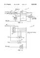
- FIG. 1is a schematic block diagram of a system that illustrates the use of a CPM generator with a DDS-driven PLL, and which can be used to implement the apparatus and method of the present invention
- FIG. 2is a schematic block diagram of an exemplary DDS that can be used to implement the apparatus and method of the present invention
- FIG. 3is a schematic block diagram of an exemplary PLL that can be used to implement the apparatus and method of the present invention
- FIG. 4is a schematic block diagram of an exemplary CPM generator that can be used to implement the apparatus and method of the present invention
- FIG. 5is a schematic block diagram of an exemplary address calculator that can be used to implement the apparatus and method of the present invention
- FIG. 6Ais a diagram that illustrates the memory contents of a memory section for a conventional GMSK DDS transmitter without a multiplying upconversion stage.
- FIG. 6Bis a diagram that illustrates the memory contents of memory section 54 in FIG. 4 for a DDS-driven PLL transmitter, in accordance with the present invention
- FIG. 6Cis a diagram that illustrates the phase states for the transmitter of FIG. 6A.
- FIG. 6Dis a diagram that illustrates the phase states for the DDS-driven PLL transmitter of FIG. 6B.
- FIG. 7is a schematic block diagram of an exemplary transmitter stage that can be used to implement the apparatus and method of the present invention.
- FIG. 8is a diagram that illustrates certain signals generated by discrete components in the continuous phase modulated, DDS-driven PLL systems shown in FIGS. 1 and 7.
- FIGS. 1-8 of the drawingslike numerals being used for like and corresponding parts of the various drawings.
- a continuous phase modulation (CPM) generatoris used to modulate the output signal of a DDS.
- the phase-modulated DDS outputdrives a PLL, which functions as an upconversion stage for a radio frequency transmitter, with the modulated DDS signal as the PLL's reference. Consequently, the frequency band of the DDS output is significantly narrower than the frequency band of upconversion stages used in conventional transmitters (e.g., without DDS-driven PLLs), and therefore, there are significantly less spurious emissions in the transmitted signal. Nevertheless, a transmitter employing the present phase-modulated DDS-driven PLL topology can still transmit over a relatively wide frequency band.
- FIG. 1is a schematic block diagram of a system that illustrates the use of a CPM generator with a DDS-driven PLL, and which can be used to implement the apparatus and method of the present invention.
- system 10generally includes a CPM generator 12, a DDS-driven PLL 14, and a clock generator 16.
- the datae.g., data or speech information
- the phase values in the sequenceare quantized on a phase modulation bus 13 and correspond to actual locations between - ⁇ and ⁇ in the IQ plane.
- the phase of the converted signalwill shift between only a limited number of phase states, which depends on the type of modulation used.
- a GMSK modulation schemeis used. How the phase of the converted signal shifts between the different states is determined by a mathematical function. This mathematical function generates a limited number of phase trajectories that are stored in a memory location (e.g., in a memory associated with CPM generator 12). Depending on the data being input to CPM generator 12, a specific phase trajectory representing the input data is output on the phase modulation bus 13 and coupled to an input of a DDS 18.
- the DDS-driven PLL 14multiplies the signal spectrum on its reference input (from bus 13) with a division ratio, N. Consequently, the modulation signal spectrum generated by the DDS stage (18) should be reduced by the same factor. As such, the number of phase states in the IQ plane are increased or scaled by the factor, N. So, the corresponding phase trajectories stored in the memory associated with CPM generator 12 are also scaled by the factor, N, which decreases the modulation index, h, by the same factor (N).
- DDS 18modulates a first intermediate frequency signal, F DDS , with the phase values input from bus 13.
- the signal, F DDScan be readily altered by loading a new digital control word in a phase accumulator in DDS 18, which advantageously enables a transmitter employing DDS-driven PLL 14 to effectuate fast frequency hopping in very small increments (e.g., smaller than 1 Hz).
- the output signal from DDS 18is bandpass filtered in filter 20 and can be mixed (as an option) by a mixer 22 with a local oscillator signal, f LO , from a clock generator 16.
- the signal output from mixer 22is bandpass filtered in filter 24, which passes one of the sidebands in the combined signal from mixer 22.
- the signal from bandpass filter 24is used as the reference signal for the PLL stage 26 and upconverted with (or multiplied by) the division ratio, N.
- This reference signalcontains the "downscaled" modulation signal spectrum, which is also multiplied by the ratio, N.
- the frequency of the output signal, SRF, from PLL stage 26is within the transmit frequency band, and can be expressed as:
- Nis the division ratio in the PLL.
- An important advantage of using system 10 and associated method as illustrated by FIG. 1is that the frequency band at the output of DDS 18 can be kept narrow enough to exclude the harmonics.
- the higher frequency bound of the signal spectrum, S DDScan be less than twice its lower frequency bound, within the same time period as the higher bound is substantially lower than the clock generator signal, f clock (which is important in order to be able to exclude harmonic aliases in the DDS output band).
- f clockwhich is important in order to be able to exclude harmonic aliases in the DDS output band.
- Another important advantage of using system 10 and associated methodis that any alteration of the modulation signal spectrum caused by the division ratio, N, can be corrected by the use of CPM generator 12 as shown.
- clock generator 16 in system 10generates a DDS clock signal, which is a harmonic of the system clock signal and functions to lock the DDS clock frequency to the system clock frequency. Consequently, by making the DDS clock an integer multiple of the system clock, the hardware required for CPM generator 12 can be significantly reduced. Also, the same clock signal (or another harmonic of the system clock) can be output from clock generator 16 and used for the local oscillator frequency, f LO , which can be mixed with the filtered DDS signal, S DDS , to upconvert the DDS signal.
- f LOlocal oscillator frequency
- FIG. 2is a schematic block diagram of an exemplary DDS (e.g., DDS 18 in FIG. 1), which can be used to implement the apparatus and method of the present invention.
- a phase modulated signal, Scan be expressed as:
- frepresents the frequency of a signal, .o slashed. represents the information to be transmitted
- Kis a constant.
- No amplitude informationcan be modulated on the resulting PLL output by the DDS reference signal.
- Thismakes the output a pure phase modulated signal without any amplitude variations, which is a significant advantage in comparing the present DDS-driven PLL transmitter with conventional transmitters employing an IQ modulator, or GMSK modulated DDS transmitters.
- the phase sequence of an analog signal, f DDSis created in a phase accumulator 30 (e.g., an unmodulated intermediate frequency signal).
- the frequency of ADDScan be digitally controlled by a constant that represents a desired output signal frequency.
- phase accumulator 30is a modulo 2 m adder (where m is the phase accumulator's buswidth) that functions to calculate a linear phase ramp.
- the phase of the ramp signalcan be incremented in steps of a frequency control word each time the adder is clocked (e.g., at the DDS clock rate).
- the signal at the output of phase accumulator 30represents angles between 0 and 2 ⁇ , and forms the first part (2 ⁇ f DDS t) of the sine argument in Equation 2.
- the modulation data, ⁇ DDSis added to the phase value from phase accumulator 30 at adder 32 to form the argument of the sine function (2 ⁇ f DDS t+ ⁇ DDS ) .
- the resulting phase valueis used as an address for a memory location in sine function table 34.
- the contents of an addressed memory locationare output from sine function table 34 and coupled to a digital-to-analog converter (DAC) 36.
- DACdigital-to-analog converter
- DDS 18functions to implement Equation 2 using the phase modulation information, ⁇ , from CPM generator 12.
- the DAC (36) in DDS 18generates several replicas of the fundamental signal being converted, so it is preferable to filter the output signal from the DDS with bandpass filter 20.
- Bandpass filter 20also functions to reduce spurious frequency components in the DDS output signal.
- Mixer 22can be used (optionally) to convert the DDS output frequency band to a higher frequency band, in order to maintain a low loop division ratio, N, in the PLL.
- Mixer 22generates both an upper and lower sideband.
- the upper sidebandis preferred in order to be able to keep the division ratio in the PLL as low as possible. Consequently, the signal output from mixer 22 is bandpass filtered in filter 24, in order to select the upper sideband for further processing, and also suppress intermodulation products.
- FIG. 3is a schematic block diagram of an exemplary PLL (e.g., PLL 26 in FIG. 1), which can be used to implement the apparatus and method of the present invention.
- PLL 26functions as a frequency multiplier, which multiplies the reference input signal, f ref , by the division ratio, N, and produces a high frequency signal(e.g., RF signal), f out , at its output. The output signal from PLL 26 is thereby locked to the reference input signal.
- the output signal, f outis generated by a voltage-controlled oscillator (VCO) 46, which is, in turn, controlled by the regulating loop of the PLL.
- VCOvoltage-controlled oscillator
- the lowpass loop filter (42) in the PLLsuppresses unwanted signals close in frequency to the desired DDS reference, which is important in order to be able to meet the stringent requirements imposed on cellular systems.
- a potential problemcan occur if the reference signal, f ref , is modulated, because the modulation spectrum (bandwidth) will be expanded by the factor, N.
- the reference signal, f refhas a modulation index that is divided by N, so that the resulting modulation spectrum (bandwidth) output from the PLL has the original modulation index.
- FIG. 4is a schematic block diagram of an exemplary CPM generator (e.g., digital CPM generator 12 in FIG. 1), which can be used to implement the apparatus and method of the present invention.
- CPM generator 12functions to transform the incoming information (to be transmitted) to a smooth, changing phase sequence.
- the output signal from CPM generator 12is coupled via the modulation bus 13 to the modulation input of DDS 18.
- information symbolsare transmitted as changes in the phase of the transmitted carrier. Since the PLL (26) functions to multiply the signal spectrum appearing at its input, CPM generator 12 takes this PLL function into account.
- the transition between the phase angles in the signal to be transmittedare predetermined by the history of incoming data, a function that depends on the modulation scheme used, and the division ratio, N, of the PLL.
- the number of possible phase states on the output bus of the PLLis N times the number of states in the IQ plane of the chosen modulation scheme.
- the phase of the signal to be transmittedcan be expressed as ⁇ (t, ⁇ ) and represents the actual phase of the transmitter's output.
- This signalcontains the information to be transmitted, which, in turn, depends on the data vector, ⁇ , and the time, t.
- Any phase modulated signalcan be described by an expansion of Equation 2, and expressed as: ##EQU1## where T is the symbol time (1/information rate), and E is the energy in one symbol. Since the energy, E, and symbol time, T, are constant, they can be understood but omitted from the following discussion.
- the data vectorcan be expressed as:
- Equation 5the phase equation for a CPM scheme can be expressed as: ##EQU2##
- the function, q(t), in Equation 5represents the phase smoothing response (a filter function) that smooths out the resulting phase trajectory between two phase states.
- the expression, ⁇ 0represents the initial phase, which is preferably set to zero.
- the modulation index, h, and the PLL division ratio, Ndetermine how much the phase is allowed to change.
- the phase pulseis zero for t ⁇ 0, and constant for t>LT, where L is the correlation length (the length of the bit history taken into account). Accordingly, Equation 5 can be expanded and expressed as: ##EQU3##
- phase statedepends on all data bits older than L, and changes in steps of h ⁇ /N.
- ⁇in Equation 6 is the state vector that represents the phase state that is "updated” each symbol interval T.
- the phase state described by Equation 6"remembers” the bit history and thus keeps the output phase (from the CPM modulator) continuous.
- the phase statecan be expressed as: ##EQU4##
- CPM generator 12includes an address calculator 52 and a memory section 54.
- memory section 54can be a programmable read-only-memory (PROM).
- Address calculator 52provides a capability of implementing numerous CPM schemes with different correlation lengths (L) and PLL division ratios (N).
- Lcorrelation lengths
- NPLL division ratios
- the incoming serial datais differentially encoded by encoder 50 (as an option), and transformed to an address sequence by address calculator 52.
- the resulting address sequencecorresponds to a specific phase trajectory stored in memory section 54.
- the phase trajectories corresponding to the addressed sequencesare output on a phase data bus, with a rate equal to the data -- clock signal multiplied by R.
- the expression, Rrepresents the number of samples per phase trajectory.
- the clock ratecan be reduced with the integration factor, I, in order to save memory space.
- the phase data rateis equal to the DDS -- clock rate/I prior to reaching the optional integrator 56, and can be increased to the DDS -- clock rate, by multiplying it with I in integrator 56. Consequently, the phase data rate at the CPM generator output can be the same as the internal rate in the DDS.
- the optimal memory space used in memory section 54is equal to 32NR/I words. This can be reduced further due to the symmetrical nature of the trajectories, but it would, in that case, require more hardware in the address calculator.
- FIG. 5is a schematic block diagram of an exemplary address calculator (e.g., address calculator 52 in FIG. 4), which can be used to implement the apparatus and method of the present invention.
- Address calculator 52functions to calculate which phase trajectory corresponds to a specific combination of incoming data bits and their history.
- address calculator 52functions to implement Equations 6 and 7 above.
- the incoming dataare shifted into register 60.
- the correlation length, Lof the incoming data bits can be adjusted to an appropriate length by controlling the number of bits that are shifted out of register 60.
- N-control wordBy inputting an up/down counter 64, the loop division ratio, N, can be compensated for, also by controlling the number of bits shifted out of register 60.
- the number of samples (R) made of the phase trajectorycan be controlled.
- the address sequence calculated by address calculator 52is input to memory section 54, which stores the corresponding phase trajectory that is output to the DDS (18).
- FIG. 6Ais a diagram that illustrates the memory contents of a memory section for a conventional GMSK DDS transmitter without a multiplying upconversion stage.
- FIG. 6Bis a diagram that illustrates the memory contents (phase trajectory) of memory section 54 in FIG. 4 for a DDS-driven PLL transmitter, in accordance with the present invention.
- FIG. 6Cis a diagram that illustrates the phase states for the transmitter of FIGURE 6A
- FIG. 6Dis a diagram that illustrates the phase states for the DDS-driven PLL transmitter of FIG. 6B.
- the phase smoothing response in Equations 5 and 6, along with the correlation length (L), modulation index (h), symbol time (T), and PLL division ratio (N)determine the memory contents of an addressed location in memory section 54 (e.g., as shown in FIGS. 6B and 6D).
- FIG. 7is a schematic block diagram of an exemplary transmitter stage, which can be used to implement the apparatus and method of the present invention.
- the continuous phase modulated, DDS-driven PLL shown in and described above with respect to FIG. 1can be used for the components denoted by numeral 10 in FIG. 7.
- the RF output signal from PLL 26is coupled to a power control and amplifier stage 27, and then transmitted from antenna 29
- the continuous phase modulated, DDS-driven PLL and transmitter output stagecan be implemented in a cellular network radio transmitter (e.g., in either a base station or mobile station), or any transmitter that uses a digital modulation scheme.
- FIG. 8is a diagram that illustrates certain signals generated by discrete components in the continuous phase modulated, DDS-driven PLL systems shown in FIGS. 1 and 7.
- the PLL division ratio, Nbeing used is 8
- the channel spacing in the DDS output being usedis about 25 kHz, which will increase 8 times to about 200 kHz after the PLL.
- the output signal spectrum, f DDSfrom DDS 18 is about 4.375 MHz wide.
- the output sidebands from mixer 22are also about 4.375 MHz wide.
- the output spectrum from the PLL (26)is 8 times wider (about 35 MHz).
- the output spectrum of a DDS used in such a systemwould be about 35 MHz wide.
- the frequency band of the DDS output in the present CPM DDS-driven PLL embodimentis significantly narrower than the frequency band of upconversion stages used in conventional transmitters (e.g., without DDS-driven PLLs), and therefore, there are significantly less spurious emissions in the transmitted signal.
- a transmitter employing the present phase-modulated DDS-driven PLL topologycan still transmit over a relatively wide frequency band.
Landscapes
- Engineering & Computer Science (AREA)
- Computer Networks & Wireless Communication (AREA)
- Signal Processing (AREA)
- Transmitters (AREA)
- Digital Transmission Methods That Use Modulated Carrier Waves (AREA)
- Stabilization Of Oscillater, Synchronisation, Frequency Synthesizers (AREA)
Abstract
Description
S.sub.RF =(f.sub.LO ±S.sub.DDS)×N, (1)
S.sub.DDS =Ksin(2πf.sub.DDS .o slashed.+φ.sub.DDS), (2)
α.sub.k ε±{1,3,5, . . . , M-1}. (4)Claims (14)
Priority Applications (9)
| Application Number | Priority Date | Filing Date | Title |
|---|---|---|---|
| US08/771,632US5834985A (en) | 1996-12-20 | 1996-12-20 | Digital continuous phase modulation for a DDS-driven phase locked loop |
| DE69712092TDE69712092T2 (en) | 1996-12-20 | 1997-12-16 | DIGITAL CONTINUOUS PHASE MODULATION FOR A PHASE CONTROL LOOP CONTROLLED BY A DIRECT DIGITAL SYNTHETIZER |
| PCT/SE1997/002121WO1998028852A2 (en) | 1996-12-20 | 1997-12-16 | Continuous phase modulator, comprising a direct digital synthesizer followed by a phase locked loop |
| KR1019997005662AKR20000069646A (en) | 1996-12-20 | 1997-12-16 | Digital continuous phase modulation for a dds-driven phase locked loop |
| CN97181693ACN1245596A (en) | 1996-12-20 | 1997-12-16 | Digital continuous phase modulation for DDS-driven phase locked loop |
| EP97951363AEP0944960B1 (en) | 1996-12-20 | 1997-12-16 | Digital continuous phase modulation for a dds-driven phase locked loop |
| AU55022/98AAU724122B2 (en) | 1996-12-20 | 1997-12-16 | Digital continuous phase modulation for a DDS-driven phase locked loop |
| BR9714050-3ABR9714050A (en) | 1996-12-20 | 1997-12-16 | Transmitter for use in a communication system, and, process for modulating an output signal from a circuit locked in phase in a radio transmitter. |
| CA002275589ACA2275589A1 (en) | 1996-12-20 | 1997-12-16 | Digital continuous phase modulation for a dds-driven phase locked loop |
Applications Claiming Priority (1)
| Application Number | Priority Date | Filing Date | Title |
|---|---|---|---|
| US08/771,632US5834985A (en) | 1996-12-20 | 1996-12-20 | Digital continuous phase modulation for a DDS-driven phase locked loop |
Publications (1)
| Publication Number | Publication Date |
|---|---|
| US5834985Atrue US5834985A (en) | 1998-11-10 |
Family
ID=25092470
Family Applications (1)
| Application Number | Title | Priority Date | Filing Date |
|---|---|---|---|
| US08/771,632Expired - LifetimeUS5834985A (en) | 1996-12-20 | 1996-12-20 | Digital continuous phase modulation for a DDS-driven phase locked loop |
Country Status (9)
| Country | Link |
|---|---|
| US (1) | US5834985A (en) |
| EP (1) | EP0944960B1 (en) |
| KR (1) | KR20000069646A (en) |
| CN (1) | CN1245596A (en) |
| AU (1) | AU724122B2 (en) |
| BR (1) | BR9714050A (en) |
| CA (1) | CA2275589A1 (en) |
| DE (1) | DE69712092T2 (en) |
| WO (1) | WO1998028852A2 (en) |
Cited By (68)
| Publication number | Priority date | Publication date | Assignee | Title |
|---|---|---|---|---|
| WO1999043080A1 (en)* | 1998-02-23 | 1999-08-26 | Tropian, Inc. | Direct digital synthesis of precise, stable angle modulated rf signal |
| US6049706A (en) | 1998-10-21 | 2000-04-11 | Parkervision, Inc. | Integrated frequency translation and selectivity |
| US6061551A (en) | 1998-10-21 | 2000-05-09 | Parkervision, Inc. | Method and system for down-converting electromagnetic signals |
| US6061555A (en) | 1998-10-21 | 2000-05-09 | Parkervision, Inc. | Method and system for ensuring reception of a communications signal |
| US6091940A (en) | 1998-10-21 | 2000-07-18 | Parkervision, Inc. | Method and system for frequency up-conversion |
| WO2000072438A1 (en)* | 1999-05-25 | 2000-11-30 | Nokia Networks Oy | Linearisation and modulation device |
| WO2001037430A1 (en)* | 1999-11-12 | 2001-05-25 | Nokia Corporation | Arrangement and method for implementing transmitter unit of digital data transmission system |
| US6262533B1 (en)* | 1998-03-18 | 2001-07-17 | Ngk Insulators, Ltd. | Starting electrode for high pressure discharge lamp |
| US6370371B1 (en) | 1998-10-21 | 2002-04-09 | Parkervision, Inc. | Applications of universal frequency translation |
| US6459742B1 (en)* | 1997-08-04 | 2002-10-01 | Eads Defence And Security Networks | Digital modulation process and modulator implementing the process |
| DE10133514A1 (en)* | 2001-07-10 | 2003-01-30 | Siemens Ag | Method and device for generating mobile radio signals |
| US6542722B1 (en) | 1998-10-21 | 2003-04-01 | Parkervision, Inc. | Method and system for frequency up-conversion with variety of transmitter configurations |
| US6560301B1 (en) | 1998-10-21 | 2003-05-06 | Parkervision, Inc. | Integrated frequency translation and selectivity with a variety of filter embodiments |
| US20030153286A1 (en)* | 2001-04-09 | 2003-08-14 | Biagio Bisanti | Radio frequency modulator |
| US6694128B1 (en) | 1998-08-18 | 2004-02-17 | Parkervision, Inc. | Frequency synthesizer using universal frequency translation technology |
| US6704549B1 (en) | 1999-03-03 | 2004-03-09 | Parkvision, Inc. | Multi-mode, multi-band communication system |
| US6704558B1 (en) | 1999-01-22 | 2004-03-09 | Parkervision, Inc. | Image-reject down-converter and embodiments thereof, such as the family radio service |
| US20040136441A1 (en)* | 2002-12-23 | 2004-07-15 | Joon-Gyu Ryu | Frequency hopping system and method thereof |
| US6813485B2 (en) | 1998-10-21 | 2004-11-02 | Parkervision, Inc. | Method and system for down-converting and up-converting an electromagnetic signal, and transforms for same |
| US20050047523A1 (en)* | 2003-09-02 | 2005-03-03 | David Shiung | [non-coherent frequency shift keying transmitter using a digital interpolation synthesizer] |
| US6873836B1 (en) | 1999-03-03 | 2005-03-29 | Parkervision, Inc. | Universal platform module and methods and apparatuses relating thereto enabled by universal frequency translation technology |
| US6879817B1 (en) | 1999-04-16 | 2005-04-12 | Parkervision, Inc. | DC offset, re-radiation, and I/Q solutions using universal frequency translation technology |
| US6963734B2 (en) | 1999-12-22 | 2005-11-08 | Parkervision, Inc. | Differential frequency down-conversion using techniques of universal frequency translation technology |
| US20050265428A1 (en)* | 2000-05-26 | 2005-12-01 | Freescale Semiconductor, Inc. | Low power, high resolution timing generator for ultra-wide bandwidth communication systems |
| US6975848B2 (en) | 2002-06-04 | 2005-12-13 | Parkervision, Inc. | Method and apparatus for DC offset removal in a radio frequency communication channel |
| US7006805B1 (en) | 1999-01-22 | 2006-02-28 | Parker Vision, Inc. | Aliasing communication system with multi-mode and multi-band functionality and embodiments thereof, such as the family radio service |
| US7010286B2 (en) | 2000-04-14 | 2006-03-07 | Parkervision, Inc. | Apparatus, system, and method for down-converting and up-converting electromagnetic signals |
| US7010559B2 (en) | 2000-11-14 | 2006-03-07 | Parkervision, Inc. | Method and apparatus for a parallel correlator and applications thereof |
| US7027786B1 (en) | 1998-10-21 | 2006-04-11 | Parkervision, Inc. | Carrier and clock recovery using universal frequency translation |
| US7039372B1 (en) | 1998-10-21 | 2006-05-02 | Parkervision, Inc. | Method and system for frequency up-conversion with modulation embodiments |
| US7054296B1 (en) | 1999-08-04 | 2006-05-30 | Parkervision, Inc. | Wireless local area network (WLAN) technology and applications including techniques of universal frequency translation |
| US7072390B1 (en) | 1999-08-04 | 2006-07-04 | Parkervision, Inc. | Wireless local area network (WLAN) using universal frequency translation technology including multi-phase embodiments |
| US7072427B2 (en) | 2001-11-09 | 2006-07-04 | Parkervision, Inc. | Method and apparatus for reducing DC offsets in a communication system |
| US7082171B1 (en) | 1999-11-24 | 2006-07-25 | Parkervision, Inc. | Phase shifting applications of universal frequency translation |
| US7085335B2 (en) | 2001-11-09 | 2006-08-01 | Parkervision, Inc. | Method and apparatus for reducing DC offsets in a communication system |
| US7110435B1 (en) | 1999-03-15 | 2006-09-19 | Parkervision, Inc. | Spread spectrum applications of universal frequency translation |
| US7110444B1 (en) | 1999-08-04 | 2006-09-19 | Parkervision, Inc. | Wireless local area network (WLAN) using universal frequency translation technology including multi-phase embodiments and circuit implementations |
| US20070080852A1 (en)* | 2005-10-07 | 2007-04-12 | Blumke Joel C | Phase locked loop as linear chirp extender |
| US7236754B2 (en) | 1999-08-23 | 2007-06-26 | Parkervision, Inc. | Method and system for frequency up-conversion |
| US7292835B2 (en) | 2000-01-28 | 2007-11-06 | Parkervision, Inc. | Wireless and wired cable modem applications of universal frequency translation technology |
| US7295826B1 (en) | 1998-10-21 | 2007-11-13 | Parkervision, Inc. | Integrated frequency translation and selectivity with gain control functionality, and applications thereof |
| US7321640B2 (en) | 2002-06-07 | 2008-01-22 | Parkervision, Inc. | Active polyphase inverter filter for quadrature signal generation |
| US7379883B2 (en) | 2002-07-18 | 2008-05-27 | Parkervision, Inc. | Networking methods and systems |
| US20080129406A1 (en)* | 2006-11-30 | 2008-06-05 | Aydin Nergis | Direct Wideband Modulation of a Frequency Synthesizer |
| US20080205543A1 (en)* | 2007-02-28 | 2008-08-28 | Ahmadreza Rofougaran | Method and System for a High-Precision Frequency Generator using a Direct Digital Frequency Synthesizer for Transmitters and Receivers |
| US20080205560A1 (en)* | 2007-02-27 | 2008-08-28 | Ahmadreza Rofougaran | Method and system for utilizing direct digital frequency synthesis to process signals in multi-band applications |
| US20080205545A1 (en)* | 2007-02-28 | 2008-08-28 | Ahmadreza Rofougaran | Method and System for Using a Phase Locked Loop for Upconversion in a Wideband Crystalless Polar Transmitter |
| US20080212707A1 (en)* | 2007-03-01 | 2008-09-04 | Ahmadreza Rofougaran | Method and system for a digital polar transmitter |
| US20080240298A1 (en)* | 2002-11-27 | 2008-10-02 | Dean Raby | Method and/or apparatus for stabilizing the frequency of digitally synthesized waveforms |
| US7454453B2 (en) | 2000-11-14 | 2008-11-18 | Parkervision, Inc. | Methods, systems, and computer program products for parallel correlation and applications thereof |
| US7460584B2 (en) | 2002-07-18 | 2008-12-02 | Parkervision, Inc. | Networking methods and systems |
| US7515896B1 (en) | 1998-10-21 | 2009-04-07 | Parkervision, Inc. | Method and system for down-converting an electromagnetic signal, and transforms for same, and aperture relationships |
| US7554508B2 (en) | 2000-06-09 | 2009-06-30 | Parker Vision, Inc. | Phased array antenna applications on universal frequency translation |
| US20090190708A1 (en)* | 2008-01-30 | 2009-07-30 | Infineon Technologies Ag | Frequency Synthesis Using Upconversion PLL Processes |
| US20090206892A1 (en)* | 2008-02-15 | 2009-08-20 | Tektronix, Inc. | Phase-Locked Loop System and Method |
| US20100073046A1 (en)* | 2007-02-28 | 2010-03-25 | Ahmadreza Rofougaran | Method and system for a fast-switching phase-locked loop using a direct digital frequency synthesizer |
| US7693230B2 (en) | 1999-04-16 | 2010-04-06 | Parkervision, Inc. | Apparatus and method of differential IQ frequency up-conversion |
| US7724845B2 (en) | 1999-04-16 | 2010-05-25 | Parkervision, Inc. | Method and system for down-converting and electromagnetic signal, and transforms for same |
| US7773688B2 (en) | 1999-04-16 | 2010-08-10 | Parkervision, Inc. | Method, system, and apparatus for balanced frequency up-conversion, including circuitry to directly couple the outputs of multiple transistors |
| CN101383614B (en)* | 2007-09-04 | 2011-02-23 | 锐迪科科技有限公司 | Pll filter |
| US20110122921A1 (en)* | 2000-10-10 | 2011-05-26 | Freescale Semiconductor, Inc. | Low power, high resolution timing generator for ultra-wide bandwidth communication systems |
| US8295406B1 (en) | 1999-08-04 | 2012-10-23 | Parkervision, Inc. | Universal platform module for a plurality of communication protocols |
| US8476945B2 (en) | 2011-03-23 | 2013-07-02 | International Business Machines Corporation | Phase profile generator |
| US20140079154A1 (en)* | 2012-09-20 | 2014-03-20 | Lsi Corporation | Direct digital synthesis of quadrature modulated signals |
| CN103873160A (en)* | 2012-12-12 | 2014-06-18 | 北京普源精电科技有限公司 | Method and device for changing phase jump of phase shift keying (PSK) |
| US20140361812A1 (en)* | 2011-12-19 | 2014-12-11 | Furuno Electric Co., Ltd. | Direct digital synthesizer, reference frequency generating device, and sine wave outputting method |
| US10778260B2 (en)* | 2018-04-20 | 2020-09-15 | Telefonaktiebolaget Lm Ericsson (Publ) | Method and apparatus for energy efficient transmission and reception of a signal using aliasing |
| US11469790B2 (en)* | 2019-07-02 | 2022-10-11 | Kbr Wyle Services, Llc | Agile navigation transmitter system |
Families Citing this family (9)
| Publication number | Priority date | Publication date | Assignee | Title |
|---|---|---|---|---|
| FR2796799B1 (en)* | 1999-07-22 | 2001-10-05 | Cit Alcatel | MODULATION METHOD AND DEVICE IN A TRANSMITTER |
| RU2239282C1 (en)* | 2003-04-01 | 2004-10-27 | Федеральное государственное унитарное предприятие "Конструкторское бюро "Луч" | Method for tuning broadband pll frequency synthesizer |
| CN100428630C (en)* | 2003-08-29 | 2008-10-22 | 华为技术有限公司 | Synchronous Digital Hierarchy System Clock and Its Generation Method |
| KR100656956B1 (en)* | 2006-01-04 | 2006-12-14 | 삼성전자주식회사 | Fast passband phase modulation device and method |
| DE102009011795A1 (en)* | 2009-03-05 | 2010-09-09 | Rohde & Schwarz Gmbh & Co. Kg | Synthesizer with adjustable, stable and reproducible phase and frequency |
| CN102468868B (en)* | 2010-11-03 | 2016-03-30 | 苏州普源精电科技有限公司 | DDS signal generator and frequency-hopping method |
| CN102412837B (en)* | 2011-11-18 | 2013-06-05 | 北京航天测控技术有限公司 | Method for realizing low spurious small-step frequency synthesizer |
| CN104393871A (en)* | 2014-12-02 | 2015-03-04 | 贵州航天计量测试技术研究所 | Frequency synthesizer for driving phase-locked loop after up-converting DDS |
| CN107995138B (en)* | 2017-12-29 | 2020-10-23 | 中国电子科技集团公司第二十研究所 | Joint Iterative Carrier Synchronization and Demodulation Method for SCCPM System |
Citations (7)
| Publication number | Priority date | Publication date | Assignee | Title |
|---|---|---|---|---|
| US4965533A (en)* | 1989-08-31 | 1990-10-23 | Qualcomm, Inc. | Direct digital synthesizer driven phase lock loop frequency synthesizer |
| US5028887A (en)* | 1989-08-31 | 1991-07-02 | Qualcomm, Inc. | Direct digital synthesizer driven phase lock loop frequency synthesizer with hard limiter |
| US5128623A (en)* | 1990-09-10 | 1992-07-07 | Qualcomm Incorporated | Direct digital synthesizer/direct analog synthesizer hybrid frequency synthesizer |
| US5291428A (en)* | 1993-03-02 | 1994-03-01 | Harris Corporation | Apparatus for reducing spurious frequency components in the output signal of a direct digital synthesizer |
| US5374903A (en)* | 1988-04-22 | 1994-12-20 | Hughes Aircraft Company | Generation of wideband linear frequency modulation signals |
| US5425055A (en)* | 1991-11-30 | 1995-06-13 | Nokia Mobile Phones (Uk) Limited | Digital radio modulator |
| US5481230A (en)* | 1994-11-14 | 1996-01-02 | Tektronix, Inc. | Phase modulator having individually placed edges |
Family Cites Families (1)
| Publication number | Priority date | Publication date | Assignee | Title |
|---|---|---|---|---|
| CN1090861C (en)* | 1995-06-08 | 2002-09-11 | 皇家菲利浦电子有限公司 | Transmission system using transmitter with phase modulator and frequency multiplier |
- 1996
- 1996-12-20USUS08/771,632patent/US5834985A/ennot_activeExpired - Lifetime
- 1997
- 1997-12-16AUAU55022/98Apatent/AU724122B2/ennot_activeCeased
- 1997-12-16WOPCT/SE1997/002121patent/WO1998028852A2/ennot_activeApplication Discontinuation
- 1997-12-16CNCN97181693Apatent/CN1245596A/enactivePending
- 1997-12-16BRBR9714050-3Apatent/BR9714050A/ennot_activeIP Right Cessation
- 1997-12-16DEDE69712092Tpatent/DE69712092T2/ennot_activeExpired - Lifetime
- 1997-12-16KRKR1019997005662Apatent/KR20000069646A/ennot_activeWithdrawn
- 1997-12-16EPEP97951363Apatent/EP0944960B1/ennot_activeExpired - Lifetime
- 1997-12-16CACA002275589Apatent/CA2275589A1/ennot_activeAbandoned
Patent Citations (7)
| Publication number | Priority date | Publication date | Assignee | Title |
|---|---|---|---|---|
| US5374903A (en)* | 1988-04-22 | 1994-12-20 | Hughes Aircraft Company | Generation of wideband linear frequency modulation signals |
| US4965533A (en)* | 1989-08-31 | 1990-10-23 | Qualcomm, Inc. | Direct digital synthesizer driven phase lock loop frequency synthesizer |
| US5028887A (en)* | 1989-08-31 | 1991-07-02 | Qualcomm, Inc. | Direct digital synthesizer driven phase lock loop frequency synthesizer with hard limiter |
| US5128623A (en)* | 1990-09-10 | 1992-07-07 | Qualcomm Incorporated | Direct digital synthesizer/direct analog synthesizer hybrid frequency synthesizer |
| US5425055A (en)* | 1991-11-30 | 1995-06-13 | Nokia Mobile Phones (Uk) Limited | Digital radio modulator |
| US5291428A (en)* | 1993-03-02 | 1994-03-01 | Harris Corporation | Apparatus for reducing spurious frequency components in the output signal of a direct digital synthesizer |
| US5481230A (en)* | 1994-11-14 | 1996-01-02 | Tektronix, Inc. | Phase modulator having individually placed edges |
Non-Patent Citations (6)
| Title |
|---|
| Digital Generation of Wideband LFM Waveforms by L.O. Eber and H.H. Soule, Jr. IEEE Int. l Radar Conference 1975, Apr. 21 23 New York pp. 170-175, XP002035956.* |
| Digital Generation of Wideband LFM Waveforms by L.O. Eber and H.H. Soule, Jr. IEEE Int.'l Radar Conference 1975, Apr. 21-23 New York pp. 170-175, XPOO2035956. |
| Novel Measurement Schemes Serve I/Q Applications by Radhakrishnaiah P.N. Setty Mini Circuits, P.O. Box 350166, Brooklyn, New York 11235 0003.* |
| Novel Measurement Schemes Serve I/Q Applications by Radhakrishnaiah P.N. Setty Mini-Circuits, P.O. Box 350166, Brooklyn, New York 11235-0003. |
| Synchronisierte Mikrowellenoszillatoren Als Leistungsverst a rker Und Frequenzteiler In Breitband Richtfunksystemen by B. v.Kameke, NTG Fachbericht, vol. 70, Apr. 23 25, 1980, Berlin pp. 243-249, XP002035871.* |
| Synchronisierte Mikrowellenoszillatoren Als Leistungsverstarker Und Frequenzteiler In Breitband-Richtfunksystemen by B. v.Kameke, NTG Fachbericht, vol. 70, Apr. 23-25, 1980, Berlin pp. 243-249, XPOO2035871. |
Cited By (153)
| Publication number | Priority date | Publication date | Assignee | Title |
|---|---|---|---|---|
| US6459742B1 (en)* | 1997-08-04 | 2002-10-01 | Eads Defence And Security Networks | Digital modulation process and modulator implementing the process |
| US5952895A (en)* | 1998-02-23 | 1999-09-14 | Tropian, Inc. | Direct digital synthesis of precise, stable angle modulated RF signal |
| WO1999043080A1 (en)* | 1998-02-23 | 1999-08-26 | Tropian, Inc. | Direct digital synthesis of precise, stable angle modulated rf signal |
| US6262533B1 (en)* | 1998-03-18 | 2001-07-17 | Ngk Insulators, Ltd. | Starting electrode for high pressure discharge lamp |
| US6694128B1 (en) | 1998-08-18 | 2004-02-17 | Parkervision, Inc. | Frequency synthesizer using universal frequency translation technology |
| US7936022B2 (en) | 1998-10-21 | 2011-05-03 | Parkervision, Inc. | Method and circuit for down-converting a signal |
| US7321735B1 (en) | 1998-10-21 | 2008-01-22 | Parkervision, Inc. | Optical down-converter using universal frequency translation technology |
| US6049706A (en) | 1998-10-21 | 2000-04-11 | Parkervision, Inc. | Integrated frequency translation and selectivity |
| US6091940A (en) | 1998-10-21 | 2000-07-18 | Parkervision, Inc. | Method and system for frequency up-conversion |
| US6266518B1 (en) | 1998-10-21 | 2001-07-24 | Parkervision, Inc. | Method and system for down-converting electromagnetic signals by sampling and integrating over apertures |
| US6353735B1 (en) | 1998-10-21 | 2002-03-05 | Parkervision, Inc. | MDG method for output signal generation |
| US6370371B1 (en) | 1998-10-21 | 2002-04-09 | Parkervision, Inc. | Applications of universal frequency translation |
| US6421534B1 (en) | 1998-10-21 | 2002-07-16 | Parkervision, Inc. | Integrated frequency translation and selectivity |
| US6061555A (en) | 1998-10-21 | 2000-05-09 | Parkervision, Inc. | Method and system for ensuring reception of a communications signal |
| US8190108B2 (en) | 1998-10-21 | 2012-05-29 | Parkervision, Inc. | Method and system for frequency up-conversion |
| US6542722B1 (en) | 1998-10-21 | 2003-04-01 | Parkervision, Inc. | Method and system for frequency up-conversion with variety of transmitter configurations |
| US6560301B1 (en) | 1998-10-21 | 2003-05-06 | Parkervision, Inc. | Integrated frequency translation and selectivity with a variety of filter embodiments |
| US6580902B1 (en) | 1998-10-21 | 2003-06-17 | Parkervision, Inc. | Frequency translation using optimized switch structures |
| US8190116B2 (en) | 1998-10-21 | 2012-05-29 | Parker Vision, Inc. | Methods and systems for down-converting a signal using a complementary transistor structure |
| US7376410B2 (en) | 1998-10-21 | 2008-05-20 | Parkervision, Inc. | Methods and systems for down-converting a signal using a complementary transistor structure |
| US6647250B1 (en) | 1998-10-21 | 2003-11-11 | Parkervision, Inc. | Method and system for ensuring reception of a communications signal |
| US6687493B1 (en) | 1998-10-21 | 2004-02-03 | Parkervision, Inc. | Method and circuit for down-converting a signal using a complementary FET structure for improved dynamic range |
| US6061551A (en) | 1998-10-21 | 2000-05-09 | Parkervision, Inc. | Method and system for down-converting electromagnetic signals |
| US7515896B1 (en) | 1998-10-21 | 2009-04-07 | Parkervision, Inc. | Method and system for down-converting an electromagnetic signal, and transforms for same, and aperture relationships |
| US7016663B2 (en) | 1998-10-21 | 2006-03-21 | Parkervision, Inc. | Applications of universal frequency translation |
| US8160534B2 (en) | 1998-10-21 | 2012-04-17 | Parkervision, Inc. | Applications of universal frequency translation |
| US7697916B2 (en) | 1998-10-21 | 2010-04-13 | Parkervision, Inc. | Applications of universal frequency translation |
| US6798351B1 (en) | 1998-10-21 | 2004-09-28 | Parkervision, Inc. | Automated meter reader applications of universal frequency translation |
| US6813485B2 (en) | 1998-10-21 | 2004-11-02 | Parkervision, Inc. | Method and system for down-converting and up-converting an electromagnetic signal, and transforms for same |
| US6836650B2 (en) | 1998-10-21 | 2004-12-28 | Parkervision, Inc. | Methods and systems for down-converting electromagnetic signals, and applications thereof |
| US7308242B2 (en) | 1998-10-21 | 2007-12-11 | Parkervision, Inc. | Method and system for down-converting and up-converting an electromagnetic signal, and transforms for same |
| US7295826B1 (en) | 1998-10-21 | 2007-11-13 | Parkervision, Inc. | Integrated frequency translation and selectivity with gain control functionality, and applications thereof |
| US7529522B2 (en) | 1998-10-21 | 2009-05-05 | Parkervision, Inc. | Apparatus and method for communicating an input signal in polar representation |
| US7245886B2 (en) | 1998-10-21 | 2007-07-17 | Parkervision, Inc. | Method and system for frequency up-conversion with modulation embodiments |
| US8019291B2 (en) | 1998-10-21 | 2011-09-13 | Parkervision, Inc. | Method and system for frequency down-conversion and frequency up-conversion |
| US7937059B2 (en) | 1998-10-21 | 2011-05-03 | Parkervision, Inc. | Converting an electromagnetic signal via sub-sampling |
| US8340618B2 (en) | 1998-10-21 | 2012-12-25 | Parkervision, Inc. | Method and system for down-converting an electromagnetic signal, and transforms for same, and aperture relationships |
| US7389100B2 (en) | 1998-10-21 | 2008-06-17 | Parkervision, Inc. | Method and circuit for down-converting a signal |
| US7039372B1 (en) | 1998-10-21 | 2006-05-02 | Parkervision, Inc. | Method and system for frequency up-conversion with modulation embodiments |
| US7218907B2 (en) | 1998-10-21 | 2007-05-15 | Parkervision, Inc. | Method and circuit for down-converting a signal |
| US7027786B1 (en) | 1998-10-21 | 2006-04-11 | Parkervision, Inc. | Carrier and clock recovery using universal frequency translation |
| US7620378B2 (en) | 1998-10-21 | 2009-11-17 | Parkervision, Inc. | Method and system for frequency up-conversion with modulation embodiments |
| US7050508B2 (en) | 1998-10-21 | 2006-05-23 | Parkervision, Inc. | Method and system for frequency up-conversion with a variety of transmitter configurations |
| US8233855B2 (en) | 1998-10-21 | 2012-07-31 | Parkervision, Inc. | Up-conversion based on gated information signal |
| US7693502B2 (en) | 1998-10-21 | 2010-04-06 | Parkervision, Inc. | Method and system for down-converting an electromagnetic signal, transforms for same, and aperture relationships |
| US7865177B2 (en) | 1998-10-21 | 2011-01-04 | Parkervision, Inc. | Method and system for down-converting an electromagnetic signal, and transforms for same, and aperture relationships |
| US7076011B2 (en) | 1998-10-21 | 2006-07-11 | Parkervision, Inc. | Integrated frequency translation and selectivity |
| US7826817B2 (en) | 1998-10-21 | 2010-11-02 | Parker Vision, Inc. | Applications of universal frequency translation |
| US7194246B2 (en) | 1998-10-21 | 2007-03-20 | Parkervision, Inc. | Methods and systems for down-converting a signal using a complementary transistor structure |
| US6704558B1 (en) | 1999-01-22 | 2004-03-09 | Parkervision, Inc. | Image-reject down-converter and embodiments thereof, such as the family radio service |
| US7006805B1 (en) | 1999-01-22 | 2006-02-28 | Parker Vision, Inc. | Aliasing communication system with multi-mode and multi-band functionality and embodiments thereof, such as the family radio service |
| US7483686B2 (en) | 1999-03-03 | 2009-01-27 | Parkervision, Inc. | Universal platform module and methods and apparatuses relating thereto enabled by universal frequency translation technology |
| US6704549B1 (en) | 1999-03-03 | 2004-03-09 | Parkvision, Inc. | Multi-mode, multi-band communication system |
| US6873836B1 (en) | 1999-03-03 | 2005-03-29 | Parkervision, Inc. | Universal platform module and methods and apparatuses relating thereto enabled by universal frequency translation technology |
| US7599421B2 (en) | 1999-03-15 | 2009-10-06 | Parkervision, Inc. | Spread spectrum applications of universal frequency translation |
| US7110435B1 (en) | 1999-03-15 | 2006-09-19 | Parkervision, Inc. | Spread spectrum applications of universal frequency translation |
| US8036304B2 (en) | 1999-04-16 | 2011-10-11 | Parkervision, Inc. | Apparatus and method of differential IQ frequency up-conversion |
| US6879817B1 (en) | 1999-04-16 | 2005-04-12 | Parkervision, Inc. | DC offset, re-radiation, and I/Q solutions using universal frequency translation technology |
| US8223898B2 (en) | 1999-04-16 | 2012-07-17 | Parkervision, Inc. | Method and system for down-converting an electromagnetic signal, and transforms for same |
| US7224749B2 (en) | 1999-04-16 | 2007-05-29 | Parkervision, Inc. | Method and apparatus for reducing re-radiation using techniques of universal frequency translation technology |
| US8224281B2 (en) | 1999-04-16 | 2012-07-17 | Parkervision, Inc. | Down-conversion of an electromagnetic signal with feedback control |
| US7894789B2 (en) | 1999-04-16 | 2011-02-22 | Parkervision, Inc. | Down-conversion of an electromagnetic signal with feedback control |
| US7773688B2 (en) | 1999-04-16 | 2010-08-10 | Parkervision, Inc. | Method, system, and apparatus for balanced frequency up-conversion, including circuitry to directly couple the outputs of multiple transistors |
| US7539474B2 (en) | 1999-04-16 | 2009-05-26 | Parkervision, Inc. | DC offset, re-radiation, and I/Q solutions using universal frequency translation technology |
| US7272164B2 (en) | 1999-04-16 | 2007-09-18 | Parkervision, Inc. | Reducing DC offsets using spectral spreading |
| US7929638B2 (en) | 1999-04-16 | 2011-04-19 | Parkervision, Inc. | Wireless local area network (WLAN) using universal frequency translation technology including multi-phase embodiments |
| US7190941B2 (en) | 1999-04-16 | 2007-03-13 | Parkervision, Inc. | Method and apparatus for reducing DC offsets in communication systems using universal frequency translation technology |
| US8077797B2 (en) | 1999-04-16 | 2011-12-13 | Parkervision, Inc. | Method, system, and apparatus for balanced frequency up-conversion of a baseband signal |
| US8229023B2 (en) | 1999-04-16 | 2012-07-24 | Parkervision, Inc. | Wireless local area network (WLAN) using universal frequency translation technology including multi-phase embodiments |
| US7693230B2 (en) | 1999-04-16 | 2010-04-06 | Parkervision, Inc. | Apparatus and method of differential IQ frequency up-conversion |
| US8594228B2 (en) | 1999-04-16 | 2013-11-26 | Parkervision, Inc. | Apparatus and method of differential IQ frequency up-conversion |
| US7724845B2 (en) | 1999-04-16 | 2010-05-25 | Parkervision, Inc. | Method and system for down-converting and electromagnetic signal, and transforms for same |
| US6647073B2 (en) | 1999-05-25 | 2003-11-11 | Nokia Corporation | Linearisation and modulation device |
| WO2000072438A1 (en)* | 1999-05-25 | 2000-11-30 | Nokia Networks Oy | Linearisation and modulation device |
| US7653145B2 (en) | 1999-08-04 | 2010-01-26 | Parkervision, Inc. | Wireless local area network (WLAN) using universal frequency translation technology including multi-phase embodiments and circuit implementations |
| US7110444B1 (en) | 1999-08-04 | 2006-09-19 | Parkervision, Inc. | Wireless local area network (WLAN) using universal frequency translation technology including multi-phase embodiments and circuit implementations |
| US8295406B1 (en) | 1999-08-04 | 2012-10-23 | Parkervision, Inc. | Universal platform module for a plurality of communication protocols |
| US7072390B1 (en) | 1999-08-04 | 2006-07-04 | Parkervision, Inc. | Wireless local area network (WLAN) using universal frequency translation technology including multi-phase embodiments |
| US7054296B1 (en) | 1999-08-04 | 2006-05-30 | Parkervision, Inc. | Wireless local area network (WLAN) technology and applications including techniques of universal frequency translation |
| US7236754B2 (en) | 1999-08-23 | 2007-06-26 | Parkervision, Inc. | Method and system for frequency up-conversion |
| US7546096B2 (en) | 1999-08-23 | 2009-06-09 | Parkervision, Inc. | Frequency up-conversion using a harmonic generation and extraction module |
| WO2001037430A1 (en)* | 1999-11-12 | 2001-05-25 | Nokia Corporation | Arrangement and method for implementing transmitter unit of digital data transmission system |
| US7082171B1 (en) | 1999-11-24 | 2006-07-25 | Parkervision, Inc. | Phase shifting applications of universal frequency translation |
| US7379515B2 (en) | 1999-11-24 | 2008-05-27 | Parkervision, Inc. | Phased array antenna applications of universal frequency translation |
| US6963734B2 (en) | 1999-12-22 | 2005-11-08 | Parkervision, Inc. | Differential frequency down-conversion using techniques of universal frequency translation technology |
| US7292835B2 (en) | 2000-01-28 | 2007-11-06 | Parkervision, Inc. | Wireless and wired cable modem applications of universal frequency translation technology |
| US7218899B2 (en) | 2000-04-14 | 2007-05-15 | Parkervision, Inc. | Apparatus, system, and method for up-converting electromagnetic signals |
| US7822401B2 (en) | 2000-04-14 | 2010-10-26 | Parkervision, Inc. | Apparatus and method for down-converting electromagnetic signals by controlled charging and discharging of a capacitor |
| US8295800B2 (en) | 2000-04-14 | 2012-10-23 | Parkervision, Inc. | Apparatus and method for down-converting electromagnetic signals by controlled charging and discharging of a capacitor |
| US7386292B2 (en) | 2000-04-14 | 2008-06-10 | Parkervision, Inc. | Apparatus, system, and method for down-converting and up-converting electromagnetic signals |
| US7010286B2 (en) | 2000-04-14 | 2006-03-07 | Parkervision, Inc. | Apparatus, system, and method for down-converting and up-converting electromagnetic signals |
| US7107028B2 (en) | 2000-04-14 | 2006-09-12 | Parkervision, Inc. | Apparatus, system, and method for up converting electromagnetic signals |
| US7496342B2 (en) | 2000-04-14 | 2009-02-24 | Parkervision, Inc. | Down-converting electromagnetic signals, including controlled discharge of capacitors |
| US7643533B2 (en)* | 2000-05-26 | 2010-01-05 | Freescale Semiconductor, Inc. | Agile clock mechanism and method for ultrawide bandwidth communications system |
| US7903778B2 (en) | 2000-05-26 | 2011-03-08 | Freescale Semiconductor, Inc. | Low power, high resolution timing generator for ultra-wide bandwidth communication systems |
| US20050265428A1 (en)* | 2000-05-26 | 2005-12-01 | Freescale Semiconductor, Inc. | Low power, high resolution timing generator for ultra-wide bandwidth communication systems |
| US20100135358A1 (en)* | 2000-05-26 | 2010-06-03 | Freescale Semiconductor Inc. | Low power, high resolution timing generator for ultra-wide bandwidth communication systems |
| US7554508B2 (en) | 2000-06-09 | 2009-06-30 | Parker Vision, Inc. | Phased array antenna applications on universal frequency translation |
| US20110122921A1 (en)* | 2000-10-10 | 2011-05-26 | Freescale Semiconductor, Inc. | Low power, high resolution timing generator for ultra-wide bandwidth communication systems |
| US8743927B2 (en) | 2000-10-10 | 2014-06-03 | Freescale Semiconductor, Inc. | Low power, high resolution timing generator for ultra-wide bandwidth communication systems |
| US8311074B2 (en) | 2000-10-10 | 2012-11-13 | Freescale Semiconductor, Inc. | Low power, high resolution timing generator for ultra-wide bandwidth communication systems |
| US7010559B2 (en) | 2000-11-14 | 2006-03-07 | Parkervision, Inc. | Method and apparatus for a parallel correlator and applications thereof |
| US7454453B2 (en) | 2000-11-14 | 2008-11-18 | Parkervision, Inc. | Methods, systems, and computer program products for parallel correlation and applications thereof |
| US7991815B2 (en) | 2000-11-14 | 2011-08-02 | Parkervision, Inc. | Methods, systems, and computer program products for parallel correlation and applications thereof |
| US7433910B2 (en) | 2000-11-14 | 2008-10-07 | Parkervision, Inc. | Method and apparatus for the parallel correlator and applications thereof |
| US7233969B2 (en) | 2000-11-14 | 2007-06-19 | Parkervision, Inc. | Method and apparatus for a parallel correlator and applications thereof |
| US7136626B2 (en)* | 2001-04-09 | 2006-11-14 | Texas Instruments Incorporated | Radio frequency modulator |
| US20030153286A1 (en)* | 2001-04-09 | 2003-08-14 | Biagio Bisanti | Radio frequency modulator |
| DE10133514A1 (en)* | 2001-07-10 | 2003-01-30 | Siemens Ag | Method and device for generating mobile radio signals |
| US20040176045A1 (en)* | 2001-07-10 | 2004-09-09 | Frank Lillie | Method and device for producing mobile radio signals |
| US8446994B2 (en) | 2001-11-09 | 2013-05-21 | Parkervision, Inc. | Gain control in a communication channel |
| US7072427B2 (en) | 2001-11-09 | 2006-07-04 | Parkervision, Inc. | Method and apparatus for reducing DC offsets in a communication system |
| US7653158B2 (en) | 2001-11-09 | 2010-01-26 | Parkervision, Inc. | Gain control in a communication channel |
| US7085335B2 (en) | 2001-11-09 | 2006-08-01 | Parkervision, Inc. | Method and apparatus for reducing DC offsets in a communication system |
| US6975848B2 (en) | 2002-06-04 | 2005-12-13 | Parkervision, Inc. | Method and apparatus for DC offset removal in a radio frequency communication channel |
| US7321640B2 (en) | 2002-06-07 | 2008-01-22 | Parkervision, Inc. | Active polyphase inverter filter for quadrature signal generation |
| US7460584B2 (en) | 2002-07-18 | 2008-12-02 | Parkervision, Inc. | Networking methods and systems |
| US8407061B2 (en) | 2002-07-18 | 2013-03-26 | Parkervision, Inc. | Networking methods and systems |
| US7379883B2 (en) | 2002-07-18 | 2008-05-27 | Parkervision, Inc. | Networking methods and systems |
| US8160196B2 (en) | 2002-07-18 | 2012-04-17 | Parkervision, Inc. | Networking methods and systems |
| US7986754B2 (en) | 2002-11-27 | 2011-07-26 | Lsi Corporation | Method and/or apparatus for stabilizing the frequency of digitally synthesized waveforms |
| US20080240298A1 (en)* | 2002-11-27 | 2008-10-02 | Dean Raby | Method and/or apparatus for stabilizing the frequency of digitally synthesized waveforms |
| US7697629B2 (en)* | 2002-11-27 | 2010-04-13 | Lsi Corporation | Method and/or apparatus for stabilizing the frequency of digitally synthesized waveforms |
| US20100172449A1 (en)* | 2002-11-27 | 2010-07-08 | Raby Dean L | Method and/or apparatus for stabilizing the frequency of digitally synthesized waveforms |
| US20040136441A1 (en)* | 2002-12-23 | 2004-07-15 | Joon-Gyu Ryu | Frequency hopping system and method thereof |
| US20050047523A1 (en)* | 2003-09-02 | 2005-03-03 | David Shiung | [non-coherent frequency shift keying transmitter using a digital interpolation synthesizer] |
| US7269228B2 (en)* | 2003-09-02 | 2007-09-11 | Novatek Microelectronics Corp. | Non-coherent frequency shift keying transmitter using a digital interpolation synthesizer |
| WO2007044717A1 (en)* | 2005-10-07 | 2007-04-19 | Raytheon Systems Co. | A phase locked loop for extending the bandwidth of a chirp signal |
| US20070080852A1 (en)* | 2005-10-07 | 2007-04-12 | Blumke Joel C | Phase locked loop as linear chirp extender |
| US7535311B2 (en) | 2006-11-30 | 2009-05-19 | Infineon Technologies Ag | Direct wideband modulation of a frequency synthesizer |
| US20080129406A1 (en)* | 2006-11-30 | 2008-06-05 | Aydin Nergis | Direct Wideband Modulation of a Frequency Synthesizer |
| US20080205560A1 (en)* | 2007-02-27 | 2008-08-28 | Ahmadreza Rofougaran | Method and system for utilizing direct digital frequency synthesis to process signals in multi-band applications |
| US8284822B2 (en)* | 2007-02-27 | 2012-10-09 | Broadcom Corporation | Method and system for utilizing direct digital frequency synthesis to process signals in multi-band applications |
| US20080205543A1 (en)* | 2007-02-28 | 2008-08-28 | Ahmadreza Rofougaran | Method and System for a High-Precision Frequency Generator using a Direct Digital Frequency Synthesizer for Transmitters and Receivers |
| US7916804B2 (en)* | 2007-02-28 | 2011-03-29 | Broadcom Corporation | Method and system for a fast-switching phase-locked loop using a direct digital frequency synthesizer |
| US7826550B2 (en)* | 2007-02-28 | 2010-11-02 | Broadcom Corp. | Method and system for a high-precision frequency generator using a direct digital frequency synthesizer for transmitters and receivers |
| US20100073046A1 (en)* | 2007-02-28 | 2010-03-25 | Ahmadreza Rofougaran | Method and system for a fast-switching phase-locked loop using a direct digital frequency synthesizer |
| US20080205545A1 (en)* | 2007-02-28 | 2008-08-28 | Ahmadreza Rofougaran | Method and System for Using a Phase Locked Loop for Upconversion in a Wideband Crystalless Polar Transmitter |
| US20080212707A1 (en)* | 2007-03-01 | 2008-09-04 | Ahmadreza Rofougaran | Method and system for a digital polar transmitter |
| US8116387B2 (en)* | 2007-03-01 | 2012-02-14 | Broadcom Corporation | Method and system for a digital polar transmitter |
| CN101383614B (en)* | 2007-09-04 | 2011-02-23 | 锐迪科科技有限公司 | Pll filter |
| US20090190708A1 (en)* | 2008-01-30 | 2009-07-30 | Infineon Technologies Ag | Frequency Synthesis Using Upconversion PLL Processes |
| US8428212B2 (en) | 2008-01-30 | 2013-04-23 | Intel Mobile Communications GmbH | Frequency synthesis using upconversion PLL processes |
| US20090206892A1 (en)* | 2008-02-15 | 2009-08-20 | Tektronix, Inc. | Phase-Locked Loop System and Method |
| US8476945B2 (en) | 2011-03-23 | 2013-07-02 | International Business Machines Corporation | Phase profile generator |
| US20140361812A1 (en)* | 2011-12-19 | 2014-12-11 | Furuno Electric Co., Ltd. | Direct digital synthesizer, reference frequency generating device, and sine wave outputting method |
| US9093996B2 (en)* | 2011-12-19 | 2015-07-28 | Furuno Electric Company Limited | Direct digital synthesizer, reference frequency generating device, and sine wave outputting method |
| US20140079154A1 (en)* | 2012-09-20 | 2014-03-20 | Lsi Corporation | Direct digital synthesis of quadrature modulated signals |
| US8848831B2 (en)* | 2012-09-20 | 2014-09-30 | Lsi Corporation | Direct digital synthesis of quadrature modulated signals |
| CN103873160A (en)* | 2012-12-12 | 2014-06-18 | 北京普源精电科技有限公司 | Method and device for changing phase jump of phase shift keying (PSK) |
| CN103873160B (en)* | 2012-12-12 | 2017-12-26 | 北京普源精电科技有限公司 | A kind of method and device for the phase hit for improving digital phase modulation |
| US10778260B2 (en)* | 2018-04-20 | 2020-09-15 | Telefonaktiebolaget Lm Ericsson (Publ) | Method and apparatus for energy efficient transmission and reception of a signal using aliasing |
| US11469790B2 (en)* | 2019-07-02 | 2022-10-11 | Kbr Wyle Services, Llc | Agile navigation transmitter system |
Also Published As
| Publication number | Publication date |
|---|---|
| CN1245596A (en) | 2000-02-23 |
| DE69712092D1 (en) | 2002-05-23 |
| WO1998028852A2 (en) | 1998-07-02 |
| BR9714050A (en) | 2000-05-09 |
| AU724122B2 (en) | 2000-09-14 |
| DE69712092T2 (en) | 2002-10-10 |
| AU5502298A (en) | 1998-07-17 |
| EP0944960A2 (en) | 1999-09-29 |
| WO1998028852A3 (en) | 1998-11-26 |
| EP0944960B1 (en) | 2002-04-17 |
| KR20000069646A (en) | 2000-11-25 |
| CA2275589A1 (en) | 1998-07-02 |
Similar Documents
| Publication | Publication Date | Title |
|---|---|---|
| US5834985A (en) | Digital continuous phase modulation for a DDS-driven phase locked loop | |
| US6047029A (en) | Post-filtered delta sigma for controlling a phase locked loop modulator | |
| JP3200184B2 (en) | Synthesizer for wireless devices | |
| US6914943B2 (en) | Signal modulation circuit and signal modulation method | |
| US6122326A (en) | High precision, low phase noise synthesizer with vector modulator | |
| US6011815A (en) | Compensated ΔΣ controlled phase locked loop modulator | |
| US5467373A (en) | Digital frequency and phase modulator for radio transmission | |
| US6415002B1 (en) | Phase and amplitude modulation of baseband signals | |
| WO2000021191A1 (en) | Method and apparatus for generating a linearly modulated signal using polar modulation | |
| WO1994022224A1 (en) | Frequency synthesizer | |
| RU95119833A (en) | POWER AMPLIFIER COMBINED WITH THE AMPLITUDE MODULATION CONTROLLER AND THE PHASE MODULATION CONTROLLER | |
| WO2000067370A1 (en) | Digital phase modulator using non-linear amplifiers and a ring oscillator | |
| Vankka | Digital frequency synthesizer/modulator for continuous-phase modulations with slow frequency hopping | |
| Meyers et al. | Synthesiser review for pan-European digital cellular radio | |
| JP2924525B2 (en) | Wireless transmission device | |
| JP2009188757A (en) | Polar modulation transmitter and modulation method | |
| JP2919328B2 (en) | Modulation circuit | |
| JP2001517012A (en) | Circuit for the formation of a modulated signal | |
| Vankka | Digital frequency synthesizer/modulator for continuous phase modulations with slow frequency hopping | |
| WO2002047344A2 (en) | Waveform generator for use in iq modulation | |
| JP2650555B2 (en) | Synchronous spread spectrum modulator | |
| JPH0399549A (en) | Radio equipment for digital communication | |
| Klymyshyn et al. | Frequency stabilized direct GMSK modulator | |
| Hindson | A Ka-band frequency synthesizer for use in a direct transmitter | |
| JP2001077710A (en) | Wireless transmission device |
Legal Events
| Date | Code | Title | Description |
|---|---|---|---|
| AS | Assignment | Owner name:TELEFONAKTIEBOLAGET LM ERICSSON (PUBL), SWEDEN Free format text:ASSIGNMENT OF ASSIGNORS INTEREST;ASSIGNOR:SUNDEGARD, BO;REEL/FRAME:008484/0055 Effective date:19970304 | |
| STCF | Information on status: patent grant | Free format text:PATENTED CASE | |
| CC | Certificate of correction | ||
| FPAY | Fee payment | Year of fee payment:4 | |
| REMI | Maintenance fee reminder mailed | ||
| FPAY | Fee payment | Year of fee payment:8 | |
| FPAY | Fee payment | Year of fee payment:12 | |
| AS | Assignment | Owner name:CLUSTER LLC, DELAWARE Free format text:ASSIGNMENT OF ASSIGNORS INTEREST;ASSIGNOR:TELEFONAKTIEBOLAGET L M ERICSSON (PUBL);REEL/FRAME:030201/0186 Effective date:20130211 | |
| AS | Assignment | Owner name:UNWIRED PLANET, LLC, NEVADA Free format text:ASSIGNMENT OF ASSIGNORS INTEREST;ASSIGNOR:CLUSTER LLC;REEL/FRAME:030219/0001 Effective date:20130213 | |
| AS | Assignment | Owner name:CLUSTER LLC, SWEDEN Free format text:NOTICE OF GRANT OF SECURITY INTEREST IN PATENTS;ASSIGNOR:UNWIRED PLANET, LLC;REEL/FRAME:030369/0601 Effective date:20130213 |