US5834759A - Tracking device having emitter groups with different emitting directions - Google Patents
Tracking device having emitter groups with different emitting directionsDownload PDFInfo
- Publication number
- US5834759A US5834759AUS08/861,597US86159797AUS5834759AUS 5834759 AUS5834759 AUS 5834759AUS 86159797 AUS86159797 AUS 86159797AUS 5834759 AUS5834759 AUS 5834759A
- Authority
- US
- United States
- Prior art keywords
- emitters
- group
- face
- cone
- emission
- Prior art date
- Legal status (The legal status is an assumption and is not a legal conclusion. Google has not performed a legal analysis and makes no representation as to the accuracy of the status listed.)
- Expired - Lifetime
Links
Images


Classifications
- G—PHYSICS
- G01—MEASURING; TESTING
- G01S—RADIO DIRECTION-FINDING; RADIO NAVIGATION; DETERMINING DISTANCE OR VELOCITY BY USE OF RADIO WAVES; LOCATING OR PRESENCE-DETECTING BY USE OF THE REFLECTION OR RERADIATION OF RADIO WAVES; ANALOGOUS ARRANGEMENTS USING OTHER WAVES
- G01S5/00—Position-fixing by co-ordinating two or more direction or position line determinations; Position-fixing by co-ordinating two or more distance determinations
- G01S5/16—Position-fixing by co-ordinating two or more direction or position line determinations; Position-fixing by co-ordinating two or more distance determinations using electromagnetic waves other than radio waves
- G01S5/163—Determination of attitude
Definitions
- This inventionrelates to tracking devices for use in tracking systems that track the position and orientation of objects. More particularly, the present invention relates to tracking devices for use in optical tracking systems.
- Tracking systemshave been used in the past to track the position and, if desired, the orientation of objects in space. Tracking systems have been used in several applications, such as robotics, industrial design, reverse engineering and motion analysis. In addition, tracking systems have been used in Image Guided Surgery to track the position and orientation of surgical instruments, such as probes, biopsy devices, endoscopes and drills, in order to display a representation of the surgical instruments on pre-acquired images of the patient.
- surgical instrumentssuch as probes, biopsy devices, endoscopes and drills
- optical tracking systemstrack the position and orientation of an object by rigidly fixing a tracking device to the object and then optically sensing the position and orientation of the tracking device in space. After the object and tracking device have been calibrated, the position and orientation of the object can be determined from the sensed position and orientation of the tracking device.
- the position and orientation of the tracking devicecan comprise three positional coordinates, x, y and z and three orientation coordinates, namely pitch, yaw and roll, in a frame of reference.
- camerasare used to optically sense the position of markers on the tracking device.
- the optical tracking systemmust have at least three 1-dimensional cameras or two 2-dimensional cameras to determine the position of the markers and thereby track the three dimensional position and orientation of the tracking device.
- a 2-dimensional cameraincludes a conventional video camera having several photo detectors arranged in a square pattern.
- a 1-dimensional cameraincludes those in which a number of photodetectors are arranged in a line. Whether three 1-dimensional cameras or two 2-dimensional cameras are used, all of the cameras must be able to simultaneously sense the same marker at the same time to determine its position in space.
- the optical tracking systemhas sufficient information to determine the position and orientation of a tracking device. This information can be used to determine the position and orientation of the object fixed to the tracking device after the object and tracking device have been properly calibrated.
- the camerascan determine the x, y, z positional coordinates and two orientation coordinates, usually pitch and yaw.
- the camerascan sense radiation from the markers on the tracking device.
- markersTwo types of markers are generally used, namely active markers and passive markers.
- Passive markersare essentially reflective devices which reflect light shined onto the passive markers from a distant light source, usually located near the cameras.
- Active markerscan be any type of emitter which emits radiation that can be sensed by the two cameras.
- the emitterscan be "strobed" by the system.
- an active systemstrobes the emitters, it individually activates one known emitter at a particular time, and thereby can determine which emitter is being viewed.
- the optical tracking systems utilizing active markerscan determine which markers are active, and therefore which markers are being tracked.
- the tracking systemknows that the marker is obscured.
- active systemsare more useful and powerful than passive systems, but active systems are also more complex and therefore suffer from a time lag in tracking the object while the emitters are strobed and are more costly.
- a further disadvantage with the optical tracking systems utilizing active markersis that the emitters used as active markers are only accurate within a "cone of accurate emission", which is generally a cone having its apex at the emitter. Slightly past this cone of accurate emission, the emitters can be seen but cannot be tracked accurately by the cameras because the emitters do not behave as a point source of light. As the angle increases further past the cone of accurate emission, the emitters eventually become invisible due to the extreme angle. Therefore, emitters used as active markers are only accurate within a specified cone of accurate emission, and are completely invisible at extreme angles.
- optical tracking systemsusually have an inherent tolerance in that the markers must be more than a predetermined distance apart for the cameras to be able to differentiate between two markers.
- markers that are spaced close togetherdo not make use of the dynamic range of the sensors, and it will be impossible to accurately determine the position and orientation of the tracking device. Therefore, the markers must be spaced on the tracking device more than this predetermined distance.
- the tracking devicecannot be so large as to make it unwieldy.
- Prior arrangements of markers designed to maintain good visibility over a large field of viewsuffer either from accuracy problems due to close spacing of markers, or tend to be large three dimensional shapes that occupy a volume that is not conducive to surgical or other procedures.
- a further disadvantage of the prior art tracking systemsis that even if the markers are separated on the tracking device more than the tolerance, at extreme angles, as the device is moved, two markers may move near each other in a line at an oblique angle to the cameras. At these extreme angles, the two markers tend to appear to the cameras as a single marker. When this happens, the markers are said to "coalesce" and the system cannot track the device.
- this inventionresides in a tracking device for use in an optical tracking system to track a position and orientation of an object, said tracking device comprising: a tracker housing having a first side and a second side, and comprising means for rigidly fixing the device to the object; a first face on the first side of said device, said first face comprising a first group of at least three emitters, the first group of emitters operable to emit radiation substantially in a first direction directed away from the first side; and a second face on the first side of said device, said second face comprising a second group of at least three emitters, the second group of emitters operable to emit radiation in a second direction directed away from the first side; and wherein the second direction is different from the first direction.
- the present inventionresides in an optical tracking system to track a position and orientation of an object
- a tracking devicecomprising: a tracker housing having a first side and a second side, and comprising means for rigidly fixing the device to the object; a first face comprising at least three face portions; a first group of at least three emitters, each emitter in the first group located on a corresponding portion of the first face, the first group of emitters operable to emit radiation substantially in a first direction directed away from the first side; a second face comprising at least three face portions; a second group of at least three emitters, each emitter in the second group located on a corresponding portion of the second face, the second group of emitters operable to emit radiation substantially in a second direction away from the first side and different from the first direction; and wherein each portion of the first face is adjacent a corresponding portion of the second face.
- the present inventionresides in an optical tracking system to track a position and orientation of an object, a tracking device comprising: a tracker housing comprising means for rigidly fixing the tracking device to the object; at least two groups of emitters, each group of emitters having at least three emitters emitting radiation in the same direction, and, each group of emitters emitting radiation in different directions; wherein the optical tracking system can track the position and orientation of the object by tracking any group of emitters; and wherein the emitters are arranged on the housing in at least three clusters, each cluster comprising one emitter from each of the groups.
- the present inventionprovides a tracking device with a large visible range in which the emitters are accurate so that the tracking device can be tracked by the optical tracking system.
- Thisis advantageous in that the operator need not be concerned during manipulation of the object that the optical tracking system will "lose sight of" the emitters and thereby not be able to accurately track the object.
- Thisis particularly important in the medical field, such as in image guided surgery, where the surgeon must be able to manipulate the object, usually a probe, during a surgical procedure without fear that the optical tracking system will not be able to accurately track the probe.
- a large visible range in which the optical tracking system can accurately sense the position of markers on a tracking deviceis desirable so that the surgeon can focus on the surgical procedure.
- a further advantage of the present inventionis that it provides a tracking device with the markers from different groups placed closely together in clusters. This minimizes the size of the tracking device by efficiently orienting the emitters on the tracking device, but does not jeopardize accuracy because the emitters from each group are separated by a predetermined distance. This also decreases the likelihood that the emitters will coalesce.
- a further advantageis that it is capable of providing uniformly good accuracy over a large visible field of view while staying compact and roughly two dimensional in shape.
- a still further advantage of the present inventionis that if emitters from one group begin to coalesce, are obscured by an object, or are no longer accurate, the system can start tracking the device with the emitters from another group. This is especially useful when the cones of emissions from two groups overlap, thereby creating a redundancy in a particular volume.
- FIG. 1shows a symbolic representation of an optical tracking system comprising a tracking device according to one embodiment of the present invention
- FIG. 2shows a view of a first side of the tracking device according to one embodiment of the present invention
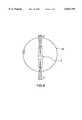
- FIG. 3shows a front view of the tracking device according to one embodiment of the present invention
- FIG. 4shows a view of a second side of the tracking device according to one embodiment of the present invention
- FIG. 5shows an isometric view of the tracking device according to one embodiment of the present invention
- FIG. 6shows a field of view of the tracking device according to one embodiment of the present invention from the side view
- FIG. 7shows a field of view of the tracking device according to one embodiment of the present invention from the front view.
- FIG. 8shows a field of view of the tracking device according to one embodiment of the present invention from the top view.
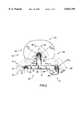
- FIG. 1shows a symbolic representation of an optical tracking system, shown generally as reference numeral 2.
- the optical tracking system 2comprises a computer 7 and two cameras 8 and 9.
- the optical tracking system 2tracks the position and orientation of the object 6 by sensing the position and orientation of the tracking device 4.
- the object 6is rigidly fixed to a tracking device 4 by means of the mounting hole 3.
- the tracking device 4is controlled by control signal C S .
- the computer 7sends the control signal C S to the tracking device 4 to selectively activate different emitters (one of which is shown in FIG. 1 by reference numeral 24) on the tracking device 4.
- the cameras 8, 9send information signals I S to the computer 7 corresponding to the sensed radiation.
- the computer 7can determine the position and orientation of the tracking device 4. If the object 6 and the tracking device 4 have been properly calibrated, the computer 7 can determine the position and orientation of the tracking device 4 and then determine the position and orientation of the object 6. Further, with prior knowledge of the geometry of the tracking device 4 and emitter placement therein, the computer 7 can select the most appropriate emitters to use in the calculation of the position and orientation of the tracking device 4.
- FIG. 2shows a side view of a first side 51 of the tracking device 4 according to one embodiment of the present invention.
- the tracking device 4comprises a first face, shown generally in FIG. 2 by reference numeral 10, and a second face, shown generally in FIG. 2 by reference numeral 20.
- the first face 10comprises a first group of at least three emitters 14, 15, 16, which are operable to emit radiation substantially in a first direction F D1 directed away from the first side 51 of the tracking device 4.
- the first face 10comprises at least the minimum number of emitters, in this case three, that the optical tracking system 2 requires to track the tracking device 4.
- the second face 20comprises at least the minimum number of emitters, in this case three, that the optical tracking system 2 requires to track the tracking device 4.
- the second group of emitters 24, 25, 26are operable to emit radiation substantially in a second direction F D2 directed away from the first side 51 and different from the first direction F D1 .
- the first group of emitters 14, 15, 16each emit radiation within a corresponding first cone of accurate emission 18.
- the cone 18will be identical for each emitter 14, 15, 16 but this need not be the case.
- the first cone 18generally has an angle ⁇ with the first direction F D1 of emission. In a preferred embodiment, the angle ⁇ is 60°.
- the second group of emitters 24, 25, 26each emit radiation within a corresponding second cone of accurate emission 28.
- the second group of emitters 24, 25, 26will be the same type of emitters as the first group of emitters 14, 15, 16 and the second cones 28 will have the same angle ⁇ with the second direction F D2 as the first cones 18 have with the first direction F D1 .
- the field of view of the first side 51 of the tracking device 4will be greater than the field of view if the tracking device 4 only had one face 10 or 20.
- the optical tracking system 2can track the position and orientation of the object 6 by tracking either the first group of emitters 14, 15, 16 on the first face 10 or the second group of emitters 24, 25, 26 on the second face 20. Because the emitters that comprise the first face 10, and the second face 20 are widely spaced, the accuracy of both faces 10 and 20 will be uniform in that there will be no transition from a widely spaced set of emitters to a closely spaced set.
- the second direction F D2should be different from the first direction F D1 so that the first group of emitters 14, 15, 16 on the first face 10 do not merely emit radiation in the same direction as the second group of emitters 24, 25, 26 on the second face 20. More preferably, the first direction F D1 and the second direction F D2 are selected such that the cone of accurate emission 18 of each of the first group of emitters 14, 15, 16 on the first face 10 combine with the cone of accurate emission 28 of each of the second group of emitters 24, 25, 26 on the second face 20 to increase or maximize the field of view of the first side 51 of the tracking device 4.
- first direction F D1 and the second direction F D2are selected such that the cone of accurate emission 18 of each emitter 14, 15, 16 on the first face 10 overlaps with a portion of the cone of accurate emission 28 of a corresponding emitter in the second group of emitters 24, 25, 26 on the second face 20.
- This overlappingis preferred to give the computer 7 the ability to select which of the emitters, namely the first group of emitters 14, 15, 16 or the second group of emitters 24, 25, 26, to track.
- the computer 7will select the group of emitters, either 14, 15, 16 or 24, 25, 26, which can be best tracked. Generally, this redundancy increases the field of view of the tracking device 4 and the accuracy of the optical tracking system 2.
- the optical tracking system 2can overcome the problem of coalescing at extreme angles using the tracking device 4. For example, if the optical tracking system 2 is tracking the first group of emitters 14, 15, 16 and two of them begin to coalesce, the optical tracking system 2 can select the second group of emitters 24, 25, 26. Because the second group of emitters 24, 25, 26 emit radiation in the second direction F D2 , which is different from the first direction F D1 , the second group of emitters 24, 25, 26 may not be coalescing and may be accurately tracked by the optical tracking system 2.
- the emitters 14, 15, 16, 24, 25, 26emit radiation in response to control signals C S . If the cameras 8, 9 fall within the cone of accurate emission 18 of each of the emitters 14, 15, 16 in the first group, then the optical tracking system 2 will track the tracking device 4 using the first group of emitters 14, 15, 16. If the cameras 8, 9 fall within the cone of accurate emission 28 of each of emitters 24, 25, 26 then the optical tracking system 2 will track the tracking device 4 using the second group of emitters 24, 25, 26.
- the optical tracking system 2can track the position and orientation of tracking device 4 from either the first group of emitters 14, 15, 16 or the second group of emitters 24, 25, 26, or some combination thereof.
- the optical tracking system 2can accurately track both groups of emitters 14, 15, 16 and 24, 25, 26 simultaneously so that a combination of emitters 14, 15, 16, 24, 25, 26 of both groups is used to determine the position and orientation of the tracking device 4.
- the cameras 8, 9will accurately see the first group of emitters 14, 15, 16 or the second group of emitters 24, 25, 26.
- the computer system 7will determine which emitters are most visible and accurate and which will be tracked, ignoring those that are inaccurate.
- each of the emitters 14, 15, 16 of the first groupare separated from each other by at least a predetermined distance.
- This predetermined distanceis ideally as large as practically possible to maximise accuracy and avoid coalescence.
- the minimum separation requiredwill be a property of the separation between cameras, the camera technology used in the optical tracking system 2 and the distance from the tracking device 4 to the cameras 8, 9.
- each of the emitters 24, 25, 26 of the second groupare also preferably separated from each other by at least this predetermined distance.
- the first face 10 and the second face 20need not be a continuous surface. Rather, as shown in FIGS. 2 and 5, the first face 10 can comprise at least three face portions 11, 12, 13. Each emitter 14, 15, 16 in the first group is located on a corresponding portion 11, 12, 13 of the first face 10. Likewise, the second face 20 need not be a continuous surface but could comprise at least three face portions 21, 22, 23. Each emitter 24, 25, 26 in the second group is located on a corresponding portion 21, 22, 23 of the second face 20.
- each emitter 14, 15, 16 of the first groupis adjacent a corresponding emitter 24, 25, 26 of the second group.
- Thisprovides a compact tracking device 4.
- this arrangementresults in each face portion 11, 12, 13 of the first face 10 being adjacent a corresponding face portion 21, 22, 23 of the second face 20.
- Face portions 11, 12, 13 of the first face 10 and the corresponding portions 21, 22, 23 of the second face 20preferably form pyramid shaped structures, as shown in FIG. 5.
- first group of emitters 14, 15, 16 and the second group of emitters 24, 25, 26are arranged on the housing 50 in at least three clusters 61, 62, 63.
- Each cluster 61, 62, 63comprises at least one emitter from each of the first group of emitters 14, 15, 16 and the second group of emitters 24, 25, 26.
- the first direction F D1 and the second direction F D2are selected such that the cones of accurate emission 18 and 28 give the optical tracking system 2 a field of view approximating a section of the sphere 72 centered at the corresponding cluster 62.
- the emitters 14, 24 on the first cluster 61 and emitters 16, 26 on the third cluster 63also give the optical tracking system 2 a field of view of clusters 61, 63 approximating a section of a sphere centered at the corresponding clusters 61, 63.
- the position of the clusters 61, 62, 63 on the housing 50are arranged to provide a maximum field of view for the optical tracking system 2.
- the housing 50is arranged as a T-shaped housing with clusters 61, 62, 63 at the ends of the arms of the "T".
- Other housing designsinclude an L-shaped housing or a triangular housing, or any other type of housing where the clusters 61, 62, 63 are separated at least by the predetermined distance and the cones of accurate emission 18 and 28 combine to give the clusters 61, 62, 63 a field of view approximating a sphere.
- the tracking device 4in a preferred embodiment, comprises a third face 30 and fourth face 40.
- the third face 30 and the fourth face 40are on the second side 52 of the tracking device 4.
- the third face 30 and the fourth face 40in a preferred embodiment, are substantially identical to the first face 10 and the second face 20 such that the tracking device 4 is symmetrical about its longitudinal axis.
- the third face 30 and the fourth face 40comprise at least three face portions 31, 32, 33 and 41, 42, 43, respectively.
- Each face portion 31, 32, 33, 41, 42, 43has a corresponding emitter 34, 35, 36, 44, 45, 46, respectively.
- Each portion 31, 32, 33 of the third face 30comprises an emitter 34, 35, 36 operable to emit radiation in a third direction F D3 .
- Each portion 41, 42, 43 of the fourth face 40comprises an emitter 44, 45, 46 operable to emit radiation in a fourth direction F D4 .
- each emitter on the third face 30emits radiation in a third cone of accurate emission 38 and each emitter on the fourth face 40 emits radiation in a fourth cone of accurate emission 48.
- the third direction F D3 and the fourth direction F D4are directed away from the second side 52, but are different from each other.
- the optical tracking system 2can track the position and orientation of the object 6 by tracking any three emitters but preferably those comprising the first group, second group, third group or fourth group of emitters.
- each portion 31, 32, 33 of the third face 30is adjacent a corresponding portion 41, 42, 43, respectively, of the fourth face 40 and a corresponding portion 11, 12, 13, respectively, of the first face 10.
- each portion 41, 42, 43 of the fourth face 40is also adjacent a corresponding portion 21, 22, 23, respectively, of the second face 20. This arrangement is seen at least from FIGS. 2, 3, 4 and 5.
- each cluster 61, 62, 63has a pyramid shape on each of the first side 51 and the second side 52 of the tracking device 4.
- the first direction F D1 , the second direction F D2 , the third direction F D3 and the fourth direction F D4are selected such that, for each cluster 61, 62, 63, the cones of accurate emission 18, 28, 38, 48 of each emitter on the clusters 61, 62, 63 combine to give a field of view of each cluster 61, 62, 63 substantially similar to a section of a sphere, and preferably approximating a half sphere centered at each of the clusters 61, 62, 63.
- FIGS. 2, 3 and 4show the field of view generally by reference numeral 72 for the second cluster 62.
- the field of view for the other clusters 61, 63will be similar to the field of view 72 for the second cluster 62, but there will be some obstruction due to the housing 50.
- the optical tracking system 2can select the emitters 14, 15, 16, 24, 25, 26, 34, 35, 36, 44, 45, 46 of the tracking device 4 which the cameras 8, 9 have the best view in order to most accurately track the tracking device 4.
- Each of the emitters 14, 15, 16, 24, 25, 26, 34, 35, 36, 44, 45, 46 on the tracking device 4can be individually activated. Because the optical tracking system 2 can select from several emitters on the tracking device 4, it is very likely that the cameras 8, 9 will fall within the cone of emission 18, 28, 38, 48 of emitters comprising one of the faces 10, 20, 30, 40 on the tracking device 4, thereby increasing he field of view of the tracking device 41 and maintaining its accuracy in that expanded field of view.
- the optical tracking system 2can strobe each of the emitters 14, 15, 16, 24, 25, 26, 34, 35, 36, 44, 45, 46 to determine whether the cameras 8, 9 can best track the position and orientation of the tracking device 4 by the first group of emitters 14, 15, 16, the second group of emitters 24, 25, 26, the third group of emitters 34, 35, 36 or the fourth group of emitters 44, 45, 46 or some combination of emitters.
- the optical tracking system 2will then use the most accurate emitters to determine the position and orientation of the tracking device 4. If the system should decide that at least three emitters are not visible or within their respective cones of accurate emission, the system will report the device as "missing", or will estimate the position as best it can and report an indication of the error involved.
- the tracking device 4comprises a light emitting diode (“LED”) 54 shown in FIG. 5.
- the LED 54emits light in the visible spectrum and can be seen by the user of the tracking device 4.
- the optical tracking system 2can track the tracking device 4 by at least three emitters 14, 15, 16, 24, 25, 26, 34, 35, 36, 44, 45, 46, the optical tracking system 2 causes the LED 54 to be continually lit indicating to the user that the object 6 is being tracked. If the tracking device 4 cannot be tracked by the optical system 2, the LED 54 is not continually lit or is flashed to warn the user that the object 6 is not being tracked.
- FIGS. 6, 7 and 8show the field of view 74 of the tracking device 4.
- FIG. 6shows the field of view 74 from the side of the tracking device 4
- FIG. 7shows the field of view 74 from the front of the tracking device 4
- FIG. 8shows the field of view 74 from the top of the tracking device 4.
- the field of view 74 of the tracking device 4is very large and approximates a section of a sphere.
- the largest "dead zone" where the cameras 8, 9 cannot view at least one of the four faces 10, 20, 30, 40is located immediately below the tracking device 4. However, this is not problematic because this is where the object 6 would likely be located in relation to the tracking device 4, and therefore this area could not be viewed by the cameras 8, 9 in any event.
- the tracking device 4is easily adaptable to track any type of object 6.
- the object 6can be a surgical instrument, such as a probe or endoscope, or the arm of a robot in an industrial application.
- the mounting hole 3can be used to rigidly fix the object 6 to the tracking device 4.
- the emitters 14, 15, 16, 24, 25, 26, 34, 35, 36, 44, 45, 46can be any type of emitters which emit radiation in a direction.
- IREDsinfrared emitting diodes
- the tracking device 4has been described in terms of having four faces 10, 20, 30, 40, the tracking device 4 could have a plurality of faces. Indeed, the greater the number of faces, the larger the field of view of the tracking device 4 because the probability that the optical tracking system 2 can find a face from the plurality of faces that can be accurately tracked increases.
- the number of faces 10, 20, 30, 40 required to give the tracking device 4 a large field of viewis a function of the size of the cone of accurate emission of the emitters used.
- the tracking device 4will remain compact and maximize the field of view of each of the clusters 61, 62, 63.
- the tracking device 4could comprise four or five or more clusters such as clusters 61, 62, 63.
- Each cluster 61, 62, 63would have at least one emitter from each of the groups.
- the tracking device 4can be used with any type of optical tracking system 2.
- the tracking device 4can be used with an optical tracking system 2 having three or more 1-dimensional cameras, or, two or more 2-dimensional cameras.
Landscapes
- Physics & Mathematics (AREA)
- Electromagnetism (AREA)
- Engineering & Computer Science (AREA)
- General Physics & Mathematics (AREA)
- Radar, Positioning & Navigation (AREA)
- Remote Sensing (AREA)
- Length Measuring Devices By Optical Means (AREA)
- Optical Radar Systems And Details Thereof (AREA)
Abstract
Description
This invention relates to tracking devices for use in tracking systems that track the position and orientation of objects. More particularly, the present invention relates to tracking devices for use in optical tracking systems.
Tracking systems have been used in the past to track the position and, if desired, the orientation of objects in space. Tracking systems have been used in several applications, such as robotics, industrial design, reverse engineering and motion analysis. In addition, tracking systems have been used in Image Guided Surgery to track the position and orientation of surgical instruments, such as probes, biopsy devices, endoscopes and drills, in order to display a representation of the surgical instruments on pre-acquired images of the patient.
In the past, there have been many different types of tracking devices for use in optical tracking systems. Generally, optical tracking systems track the position and orientation of an object by rigidly fixing a tracking device to the object and then optically sensing the position and orientation of the tracking device in space. After the object and tracking device have been calibrated, the position and orientation of the object can be determined from the sensed position and orientation of the tracking device. The position and orientation of the tracking device can comprise three positional coordinates, x, y and z and three orientation coordinates, namely pitch, yaw and roll, in a frame of reference.
In optical tracking systems, cameras are used to optically sense the position of markers on the tracking device. In general, the optical tracking system must have at least three 1-dimensional cameras or two 2-dimensional cameras to determine the position of the markers and thereby track the three dimensional position and orientation of the tracking device. A 2-dimensional camera includes a conventional video camera having several photo detectors arranged in a square pattern. A 1-dimensional camera includes those in which a number of photodetectors are arranged in a line. Whether three 1-dimensional cameras or two 2-dimensional cameras are used, all of the cameras must be able to simultaneously sense the same marker at the same time to determine its position in space.
With the positional information of at least three markers, the optical tracking system has sufficient information to determine the position and orientation of a tracking device. This information can be used to determine the position and orientation of the object fixed to the tracking device after the object and tracking device have been properly calibrated. In the event only two markers can be tracked, the cameras can determine the x, y, z positional coordinates and two orientation coordinates, usually pitch and yaw.
The cameras can sense radiation from the markers on the tracking device. Two types of markers are generally used, namely active markers and passive markers. Passive markers are essentially reflective devices which reflect light shined onto the passive markers from a distant light source, usually located near the cameras. Active markers can be any type of emitter which emits radiation that can be sensed by the two cameras.
In tracking systems using passive markers, typically retroreflective markers are attached to the tracking device. One difficulty with passive optical systems is that all of the markers continually reflect light from the same light source. In other words, passive markers are continually "lit". As such, if three markers are being tracked, it is difficult for the cameras to determine which markers are being viewed. This is especially problematic if one or more of the markers becomes obscured, as occasionally happens. The tracking system must then determine which markers are still being viewed and tracked and which markers have been obscured.
In tracking systems using active markers, the emitters can be "strobed" by the system. When an active system strobes the emitters, it individually activates one known emitter at a particular time, and thereby can determine which emitter is being viewed. In this way, the optical tracking systems utilizing active markers can determine which markers are active, and therefore which markers are being tracked. In addition, if the two cameras cannot sense a marker which the system has activated, then the tracking system knows that the marker is obscured. Generally, active systems are more useful and powerful than passive systems, but active systems are also more complex and therefore suffer from a time lag in tracking the object while the emitters are strobed and are more costly.
A further disadvantage with the optical tracking systems utilizing active markers is that the emitters used as active markers are only accurate within a "cone of accurate emission", which is generally a cone having its apex at the emitter. Slightly past this cone of accurate emission, the emitters can be seen but cannot be tracked accurately by the cameras because the emitters do not behave as a point source of light. As the angle increases further past the cone of accurate emission, the emitters eventually become invisible due to the extreme angle. Therefore, emitters used as active markers are only accurate within a specified cone of accurate emission, and are completely invisible at extreme angles.
Also, optical tracking systems usually have an inherent tolerance in that the markers must be more than a predetermined distance apart for the cameras to be able to differentiate between two markers. In addition, markers that are spaced close together do not make use of the dynamic range of the sensors, and it will be impossible to accurately determine the position and orientation of the tracking device. Therefore, the markers must be spaced on the tracking device more than this predetermined distance. However, at the same time, the tracking device cannot be so large as to make it unwieldy. Prior arrangements of markers designed to maintain good visibility over a large field of view suffer either from accuracy problems due to close spacing of markers, or tend to be large three dimensional shapes that occupy a volume that is not conducive to surgical or other procedures.
A further disadvantage of the prior art tracking systems is that even if the markers are separated on the tracking device more than the tolerance, at extreme angles, as the device is moved, two markers may move near each other in a line at an oblique angle to the cameras. At these extreme angles, the two markers tend to appear to the cameras as a single marker. When this happens, the markers are said to "coalesce" and the system cannot track the device.
Accordingly, it is an object of this invention to at least partially overcome the disadvantages of the prior art. Also, it is an object of this invention to provide an improved type of tracking device for use in optical tracking systems. Also, it is an object of this invention to provide a tracking device which has a large visible range in which the emitters are accurate.
Accordingly, in one of its objects, this invention resides in a tracking device for use in an optical tracking system to track a position and orientation of an object, said tracking device comprising: a tracker housing having a first side and a second side, and comprising means for rigidly fixing the device to the object; a first face on the first side of said device, said first face comprising a first group of at least three emitters, the first group of emitters operable to emit radiation substantially in a first direction directed away from the first side; and a second face on the first side of said device, said second face comprising a second group of at least three emitters, the second group of emitters operable to emit radiation in a second direction directed away from the first side; and wherein the second direction is different from the first direction.
In a further aspect, the present invention resides in an optical tracking system to track a position and orientation of an object, a tracking device comprising: a tracker housing having a first side and a second side, and comprising means for rigidly fixing the device to the object; a first face comprising at least three face portions; a first group of at least three emitters, each emitter in the first group located on a corresponding portion of the first face, the first group of emitters operable to emit radiation substantially in a first direction directed away from the first side; a second face comprising at least three face portions; a second group of at least three emitters, each emitter in the second group located on a corresponding portion of the second face, the second group of emitters operable to emit radiation substantially in a second direction away from the first side and different from the first direction; and wherein each portion of the first face is adjacent a corresponding portion of the second face.
In a still further aspect, the present invention resides in an optical tracking system to track a position and orientation of an object, a tracking device comprising: a tracker housing comprising means for rigidly fixing the tracking device to the object; at least two groups of emitters, each group of emitters having at least three emitters emitting radiation in the same direction, and, each group of emitters emitting radiation in different directions; wherein the optical tracking system can track the position and orientation of the object by tracking any group of emitters; and wherein the emitters are arranged on the housing in at least three clusters, each cluster comprising one emitter from each of the groups.
Accordingly, the present invention provides a tracking device with a large visible range in which the emitters are accurate so that the tracking device can be tracked by the optical tracking system. This is advantageous in that the operator need not be concerned during manipulation of the object that the optical tracking system will "lose sight of" the emitters and thereby not be able to accurately track the object. This is particularly important in the medical field, such as in image guided surgery, where the surgeon must be able to manipulate the object, usually a probe, during a surgical procedure without fear that the optical tracking system will not be able to accurately track the probe. Clearly, a large visible range in which the optical tracking system can accurately sense the position of markers on a tracking device is desirable so that the surgeon can focus on the surgical procedure.
A further advantage of the present invention is that it provides a tracking device with the markers from different groups placed closely together in clusters. This minimizes the size of the tracking device by efficiently orienting the emitters on the tracking device, but does not jeopardize accuracy because the emitters from each group are separated by a predetermined distance. This also decreases the likelihood that the emitters will coalesce. A further advantage is that it is capable of providing uniformly good accuracy over a large visible field of view while staying compact and roughly two dimensional in shape.
A still further advantage of the present invention is that if emitters from one group begin to coalesce, are obscured by an object, or are no longer accurate, the system can start tracking the device with the emitters from another group. This is especially useful when the cones of emissions from two groups overlap, thereby creating a redundancy in a particular volume.
Further aspects of the invention will become apparent upon reading the following detailed description and drawings which illustrate the invention and preferred embodiments of the invention.
In the drawings, which illustrate embodiments of the invention:
FIG. 1 shows a symbolic representation of an optical tracking system comprising a tracking device according to one embodiment of the present invention;
FIG. 2 shows a view of a first side of the tracking device according to one embodiment of the present invention;
FIG. 3 shows a front view of the tracking device according to one embodiment of the present invention;
FIG. 4 shows a view of a second side of the tracking device according to one embodiment of the present invention;
FIG. 5 shows an isometric view of the tracking device according to one embodiment of the present invention;
FIG. 6 shows a field of view of the tracking device according to one embodiment of the present invention from the side view;
FIG. 7 shows a field of view of the tracking device according to one embodiment of the present invention from the front view; and
FIG. 8 shows a field of view of the tracking device according to one embodiment of the present invention from the top view.
FIG. 1 shows a symbolic representation of an optical tracking system, shown generally asreference numeral 2. Theoptical tracking system 2 comprises a computer 7 and two cameras 8 and 9. Theoptical tracking system 2 tracks the position and orientation of the object 6 by sensing the position and orientation of thetracking device 4.
The object 6 is rigidly fixed to atracking device 4 by means of the mountinghole 3. Thetracking device 4 is controlled by control signal CS. The computer 7 sends the control signal CS to thetracking device 4 to selectively activate different emitters (one of which is shown in FIG. 1 by reference numeral 24) on thetracking device 4.
The cameras 8, 9 send information signals IS to the computer 7 corresponding to the sensed radiation. With the information signals IS, and knowing which emitters have been activated, the computer 7 can determine the position and orientation of thetracking device 4. If the object 6 and thetracking device 4 have been properly calibrated, the computer 7 can determine the position and orientation of thetracking device 4 and then determine the position and orientation of the object 6. Further, with prior knowledge of the geometry of thetracking device 4 and emitter placement therein, the computer 7 can select the most appropriate emitters to use in the calculation of the position and orientation of thetracking device 4.
FIG. 2 shows a side view of afirst side 51 of thetracking device 4 according to one embodiment of the present invention. As shown in FIG. 2, thetracking device 4 comprises a first face, shown generally in FIG. 2 byreference numeral 10, and a second face, shown generally in FIG. 2 byreference numeral 20. Thefirst face 10 comprises a first group of at least threeemitters first side 51 of thetracking device 4. Accordingly, thefirst face 10 comprises at least the minimum number of emitters, in this case three, that theoptical tracking system 2 requires to track thetracking device 4. In the same way, thesecond face 20 comprises at least the minimum number of emitters, in this case three, that theoptical tracking system 2 requires to track thetracking device 4. The second group ofemitters first side 51 and different from the first direction FD1.
The first group ofemitters accurate emission 18. As theemitters cone 18 will be identical for eachemitter first cone 18 generally has an angle α with the first direction FD1 of emission. In a preferred embodiment, the angle α is 60°. Similarly, the second group ofemitters accurate emission 28. Preferably, the second group ofemitters emitters second cones 28 will have the same angle α with the second direction FD2 as thefirst cones 18 have with the first direction FD1.
Because thefirst face 10 and thesecond face 20 are both on thefirst side 51 of thetracking device 4, the field of view of thefirst side 51 of thetracking device 4 will be greater than the field of view if thetracking device 4 only had oneface optical tracking system 2 can track the position and orientation of the object 6 by tracking either the first group ofemitters first face 10 or the second group ofemitters second face 20. Because the emitters that comprise thefirst face 10, and thesecond face 20 are widely spaced, the accuracy of both faces 10 and 20 will be uniform in that there will be no transition from a widely spaced set of emitters to a closely spaced set.
The second direction FD2 should be different from the first direction FD1 so that the first group ofemitters first face 10 do not merely emit radiation in the same direction as the second group ofemitters second face 20. More preferably, the first direction FD1 and the second direction FD2 are selected such that the cone ofaccurate emission 18 of each of the first group ofemitters first face 10 combine with the cone ofaccurate emission 28 of each of the second group ofemitters second face 20 to increase or maximize the field of view of thefirst side 51 of thetracking device 4.
It is also preferable that the first direction FD1 and the second direction FD2 are selected such that the cone ofaccurate emission 18 of eachemitter first face 10 overlaps with a portion of the cone ofaccurate emission 28 of a corresponding emitter in the second group ofemitters second face 20. This overlapping is preferred to give the computer 7 the ability to select which of the emitters, namely the first group ofemitters emitters tracking device 4 and the accuracy of theoptical tracking system 2.
Also, theoptical tracking system 2 can overcome the problem of coalescing at extreme angles using thetracking device 4. For example, if theoptical tracking system 2 is tracking the first group ofemitters optical tracking system 2 can select the second group ofemitters emitters emitters optical tracking system 2.
In a preferred embodiment, theemitters accurate emission 18 of each of theemitters optical tracking system 2 will track thetracking device 4 using the first group ofemitters accurate emission 28 of each ofemitters optical tracking system 2 will track thetracking device 4 using the second group ofemitters optical tracking system 2 can track the position and orientation of trackingdevice 4 from either the first group ofemitters emitters optical tracking system 2 can accurately track both groups ofemitters emitters tracking device 4. In general, the cameras 8, 9 will accurately see the first group ofemitters emitters
Preferably, each of theemitters optical tracking system 2 and the distance from thetracking device 4 to the cameras 8, 9. For the same reasons, each of theemitters
Because the first group ofemitters emitters first face 10 and thesecond face 20 need not be a continuous surface. Rather, as shown in FIGS. 2 and 5, thefirst face 10 can comprise at least threeface portions emitter portion first face 10. Likewise, thesecond face 20 need not be a continuous surface but could comprise at least threeface portions emitter portion second face 20.
In order to minimize the size of thetracking device 4, it is preferable that eachemitter emitter compact tracking device 4. As seen in FIG. 2, this arrangement results in eachface portion first face 10 being adjacent acorresponding face portion second face 20. Faceportions first face 10 and the correspondingportions second face 20 preferably form pyramid shaped structures, as shown in FIG. 5.
In addition, the first group ofemitters emitters housing 50 in at least threeclusters cluster emitters emitters accurate emission sphere 72 centered at the correspondingcluster 62. While not shown in the Figures, theemitters first cluster 61 andemitters third cluster 63 also give the optical tracking system 2 a field of view ofclusters clusters
Also, the position of theclusters housing 50 are arranged to provide a maximum field of view for theoptical tracking system 2. In the embodiment shown in FIG. 2, thehousing 50 is arranged as a T-shaped housing withclusters clusters accurate emission clusters
As can be seen from FIGS. 3, 4 and 5, thetracking device 4, in a preferred embodiment, comprises a third face 30 andfourth face 40. The third face 30 and thefourth face 40 are on thesecond side 52 of thetracking device 4. The third face 30 and thefourth face 40, in a preferred embodiment, are substantially identical to thefirst face 10 and thesecond face 20 such that thetracking device 4 is symmetrical about its longitudinal axis. In other words, the third face 30 and thefourth face 40 comprise at least threeface portions
Eachface portion emitter portion emitter portion fourth face 40 comprises anemitter accurate emission 38 and each emitter on thefourth face 40 emits radiation in a fourth cone ofaccurate emission 48.
The third direction FD3 and the fourth direction FD4 are directed away from thesecond side 52, but are different from each other. Theoptical tracking system 2 can track the position and orientation of the object 6 by tracking any three emitters but preferably those comprising the first group, second group, third group or fourth group of emitters.
To minimize the size of thetracking device 4, preferably, eachportion portion fourth face 40 and a correspondingportion first face 10. Likewise, eachportion fourth face 40 is also adjacent a correspondingportion second face 20. This arrangement is seen at least from FIGS. 2, 3, 4 and 5.
As also shown in FIGS. 3, 4 and 5, preferably, at least one emitter from each of the first group, second group, third group and fourth group is arranged in the threeclusters cluster first side 51 and thesecond side 52 of thetracking device 4.
As shown in FIG. 3, the first direction FD1, the second direction FD2, the third direction FD3 and the fourth direction FD4 are selected such that, for eachcluster accurate emission clusters cluster clusters reference numeral 72 for thesecond cluster 62. The field of view for theother clusters view 72 for thesecond cluster 62, but there will be some obstruction due to thehousing 50.
Theoptical tracking system 2 can select theemitters tracking device 4 which the cameras 8, 9 have the best view in order to most accurately track thetracking device 4. Each of theemitters tracking device 4 can be individually activated. Because theoptical tracking system 2 can select from several emitters on thetracking device 4, it is very likely that the cameras 8, 9 will fall within the cone ofemission faces tracking device 4, thereby increasing he field of view of thetracking device 41 and maintaining its accuracy in that expanded field of view.
At initial start-up, theoptical tracking system 2 can strobe each of theemitters tracking device 4 by the first group ofemitters emitters emitters emitters optical tracking system 2 will then use the most accurate emitters to determine the position and orientation of thetracking device 4. If the system should decide that at least three emitters are not visible or within their respective cones of accurate emission, the system will report the device as "missing", or will estimate the position as best it can and report an indication of the error involved.
Preferably, thetracking device 4 comprises a light emitting diode ("LED") 54 shown in FIG. 5. TheLED 54 emits light in the visible spectrum and can be seen by the user of thetracking device 4. When theoptical tracking system 2 can track thetracking device 4 by at least threeemitters optical tracking system 2 causes theLED 54 to be continually lit indicating to the user that the object 6 is being tracked. If thetracking device 4 cannot be tracked by theoptical system 2, theLED 54 is not continually lit or is flashed to warn the user that the object 6 is not being tracked.
FIGS. 6, 7 and 8 show the field ofview 74 of thetracking device 4. FIG. 6 shows the field ofview 74 from the side of thetracking device 4, FIG. 7 shows the field ofview 74 from the front of thetracking device 4 and FIG. 8 shows the field ofview 74 from the top of thetracking device 4. As can be seen from FIGS. 6, 7 and 8, the field ofview 74 of thetracking device 4 is very large and approximates a section of a sphere. The largest "dead zone" where the cameras 8, 9 cannot view at least one of the four faces 10, 20, 30, 40 is located immediately below thetracking device 4. However, this is not problematic because this is where the object 6 would likely be located in relation to thetracking device 4, and therefore this area could not be viewed by the cameras 8, 9 in any event.
It is understood that thetracking device 4 is easily adaptable to track any type of object 6. The object 6 can be a surgical instrument, such as a probe or endoscope, or the arm of a robot in an industrial application. In either case, the mountinghole 3 can be used to rigidly fix the object 6 to thetracking device 4.
It is further understood that theemitters
It is understood that, while thetracking device 4 has been described in terms of having four faces 10, 20, 30, 40, thetracking device 4 could have a plurality of faces. Indeed, the greater the number of faces, the larger the field of view of thetracking device 4 because the probability that theoptical tracking system 2 can find a face from the plurality of faces that can be accurately tracked increases. The number offaces
It is understood that by arranging the emitters from each of the groups inclusters tracking device 4 will remain compact and maximize the field of view of each of theclusters clusters tracking device 4 could comprise four or five or more clusters such asclusters cluster
It is further understood that while the invention has been described in terms of a particularoptical tracking system 2, thetracking device 4 can be used with any type ofoptical tracking system 2. In particular, thetracking device 4 can be used with anoptical tracking system 2 having three or more 1-dimensional cameras, or, two or more 2-dimensional cameras.
It will be understood that, although various features of the invention have been described with respect to one or another of the embodiments of the invention, the various features and embodiments of the invention may be combined or used in conjunction with other features and embodiments of the invention as described and illustrated herein.
Although this disclosure has described and illustrated certain preferred embodiments of the invention, it is to be understood that the invention is not restricted to these particular embodiments. Rather, the invention includes all embodiments which are functional, mechanical or electrical equivalents of the specific embodiments and features that have been described and illustrated herein.
Claims (20)
1. A tracking device for use in an optical tracking system to track a position and orientation of an object, said tracking device comprising:
a tracker housing having a first side and a second side, and comprising means for rigidly fixing the device to the object;
a first face on the first side of said device, said first face comprising a first group of at least three emitters, the first group of emitters operable to emit radiation substantially in a first direction directed away from the first side; and
a second face on the first side of said device, said second face comprising a second group of at least three emitters, the second group of emitters operable to emit radiation in a second direction directed away from the first side; and
wherein the second direction is different from the first direction.
2. The device as claimed in claim 1 wherein the tracking system can track the position and orientation of the object by tracking either the first group of emitters or the second group of emitters.
3. The device as claimed in claim 1 wherein the first group of emitters emit radiation in response to control signals from the optical tracking system and the second group of emitters emit radiation in response to the control signals from the optical tracking system, and the optical tracking system can track the position and orientation of the tracking device from the first group of emitters or the second group of emitters.
4. The device as claimed in claim 2 wherein each of the emitters of the first group of emitters emit radiation within a first cone of emission;
wherein each of the emitters of the second group of emitters emit radiation within a second cone of emission;
wherein the first direction and the second direction are selected such that the first cone of emission of each of the first group of emitters and the second cone of emission of each of the second group of emitters combine to provide a field of view of the first side which is greater than the first cones alone.
5. The device as claimed in claim 2 wherein each of the emitters of the first group emit radiation within a first cone of emission;
wherein each of the emitters of the second group emit radiation within a second cone of emission;
wherein the first direction and the second direction are selected such that the first cone of emission of each emitter in the first group of emitters overlaps a portion of the second cone of emission of a corresponding emitter in the second group of emitters.
6. The device as claimed in claim 4 wherein each of the emitters of the first group is separated from each of the other emitters in the first group by at least a predetermined distance, and each of the emitters of the second group are separated from each of the other emitters in the second group by at least the predetermined distance, said predetermined distance corresponding to a tolerance of the tracking system.
7. The device as claimed in claim 6 wherein each emitter of the first group is adjacent a corresponding emitter of the second group.
8. The device as claimed in claim 6 further comprising:
a third face on the second side of said device, said third face comprising a third group of at least three emitters, the third group of emitters operable to emit radiation substantially in a third direction directed away from the second side; and
a fourth face on the second side of said device, said fourth side comprising a fourth group of at least three emitters, the fourth group of emitters operable to emit radiation in a fourth direction directed away from the second side;
wherein the third direction is different from the fourth direction; and
wherein the tracking system can track the position and orientation of the object by tracking any one of the first group, second group, third group or fourth group of emitters.
9. The device as claimed in claim 8 wherein at least one emitter from each of the first group, second group, third group and fourth group of emitters is arranged in a cluster of emitters.
10. The device as claimed in claim 8 wherein the emitters from the first, second, third and fourth groups are arranged in at least three clusters of emitters, each cluster comprising one emitter from each of the first, second, third and fourth groups.
11. The device as claimed in claim 10 wherein each of the emitters of the third group emit radiation within a third cone of emission;
wherein each of the emitters of the fourth group emit radiation within a fourth cone of emission;
wherein the first direction, the second direction, the third direction and the fourth direction are selected such that for each cluster of emitters, the first cone of emission of the emitter of the first group, the second cone of emission of the emitter of the second group, the third cone of emission of the emitter of the third group and the fourth cone of emission of the emitter of the fourth group combine to give a field of view of each cluster on the device approximating a half sphere.
12. In an optical tracking system to track a position and orientation of an object, a tracking device comprising:
a tracker housing having a first side and a second side, and comprising means for rigidly fixing the device to the object;
a first face comprising at least three face portions;
a first group of at least three emitters, each emitter in the first group located on a corresponding portion of the first face, the first group of emitters operable to emit radiation substantially in a first direction directed away from the first side;
a second face comprising at least three face portions;
a second group of at least three emitters, each emitter in the second group located on a corresponding portion of the second face, the second group of emitters operable to emit radiation substantially in a second direction away from the first side and different from the first direction; and
wherein each portion of the first face is adjacent a corresponding portion of the second face.
13. The device as claimed in claim 12 wherein the tracking system can track the position and orientation of the object by tracking either the first group of emitters or the second group of emitters.
14. The device as claimed in claim 13 wherein each of the emitters of the first group of emitters emit radiation within a first cone of emission;
wherein each of the emitters of the second group of emitters emit radiation within a second cone of emission;
wherein the first direction and the second direction are selected such that the first cone of emission of each of the first group of emitters and the second cone of emission of each of the second group of emitters combine to provide a field of view of the first side of the device which is greater than the first cones.
15. The device as claimed in claim 13 further comprising:
a third face comprising at least three face portions;
a third group of at least three emitters, each emitter in the third group located on a corresponding portion of the third face, the third group of emitters operable to emit radiation substantially in a third direction directed away from the second side;
a fourth face comprising at least three face portions;
a fourth group of at least three emitters, each emitter in the fourth group located on a corresponding portion of the fourth face, the fourth group of emitters operable to emit radiation substantially in a fourth direction away from the second side and different from the third direction; and
wherein each portion of the third face is adjacent a corresponding portion of the fourth face and the first face.
16. The device as claimed in claim 15 wherein the emitters from the first, second, third and fourth groups are arranged in at least three clusters of emitters, each cluster comprising one emitter from each of the first, second, third and fourth groups and each of the clusters separated from each of the other clusters by at least a predetermined distance, said predetermined distance corresponding to a tolerance of the tracking system.
17. The device as claimed in claim 16 wherein each of the emitters emit radiation in a cone of emission; and
wherein the first direction, the second direction, the third direction and the fourth direction are selected such that, for each cluster of emitters, the cone of emission of the emitters combine to provide a field of view substantially similar to a section of a sphere centered at the corresponding cluster.
18. In an optical tracking system to track a position and orientation of an object, a tracking device comprising:
a tracker housing comprising means for rigidly fixing the tracking device to the object;
at least two groups of emitters, each group of emitters having at least three emitters emitting radiation in the same direction, and, each group of emitters emitting radiation in different directions;
wherein the optical tracking system can track the position and orientation of the object by tracking any group of emitters; and
wherein the emitters are arranged on the housing in at least three clusters, each cluster comprising one emitter from each of the groups.
19. The device as claimed in claim 18 wherein the direction of the groups of emitters are selected such that the optical tracking system has a field of view of each cluster approximating a half sphere centered at the corresponding cluster.
20. The device as claimed in claim 19 wherein there are at least three groups of emitters and each of the clusters are separated from each of the other clusters by at least a predetermined distance, said predetermined distance corresponding to a tolerance of the tracking system.
Priority Applications (2)
| Application Number | Priority Date | Filing Date | Title |
|---|---|---|---|
| US08/861,597US5834759A (en) | 1997-05-22 | 1997-05-22 | Tracking device having emitter groups with different emitting directions |
| CA002230411ACA2230411C (en) | 1997-05-22 | 1998-02-25 | Tracking device |
Applications Claiming Priority (1)
| Application Number | Priority Date | Filing Date | Title |
|---|---|---|---|
| US08/861,597US5834759A (en) | 1997-05-22 | 1997-05-22 | Tracking device having emitter groups with different emitting directions |
Publications (1)
| Publication Number | Publication Date |
|---|---|
| US5834759Atrue US5834759A (en) | 1998-11-10 |
Family
ID=25336240
Family Applications (1)
| Application Number | Title | Priority Date | Filing Date |
|---|---|---|---|
| US08/861,597Expired - LifetimeUS5834759A (en) | 1997-05-22 | 1997-05-22 | Tracking device having emitter groups with different emitting directions |
Country Status (2)
| Country | Link |
|---|---|
| US (1) | US5834759A (en) |
| CA (1) | CA2230411C (en) |
Cited By (116)
| Publication number | Priority date | Publication date | Assignee | Title |
|---|---|---|---|---|
| US6118845A (en) | 1998-06-29 | 2000-09-12 | Surgical Navigation Technologies, Inc. | System and methods for the reduction and elimination of image artifacts in the calibration of X-ray imagers |
| US6226548B1 (en) | 1997-09-24 | 2001-05-01 | Surgical Navigation Technologies, Inc. | Percutaneous registration apparatus and method for use in computer-assisted surgical navigation |
| US6226418B1 (en) | 1997-11-07 | 2001-05-01 | Washington University | Rapid convolution based large deformation image matching via landmark and volume imagery |
| US6235038B1 (en) | 1999-10-28 | 2001-05-22 | Medtronic Surgical Navigation Technologies | System for translation of electromagnetic and optical localization systems |
| US6253210B1 (en) | 1997-04-11 | 2001-06-26 | Surgical Navigation Technologies, Inc. | Method and apparatus for producing and accessing composite data |
| US6340363B1 (en) | 1998-10-09 | 2002-01-22 | Surgical Navigation Technologies, Inc. | Image guided vertebral distractor and method for tracking the position of vertebrae |
| US6348058B1 (en) | 1997-12-12 | 2002-02-19 | Surgical Navigation Technologies, Inc. | Image guided spinal surgery guide, system, and method for use thereof |
| US6381485B1 (en) | 1999-10-28 | 2002-04-30 | Surgical Navigation Technologies, Inc. | Registration of human anatomy integrated for electromagnetic localization |
| US6408107B1 (en) | 1996-07-10 | 2002-06-18 | Michael I. Miller | Rapid convolution based large deformation image matching via landmark and volume imagery |
| US20020095083A1 (en)* | 1997-03-11 | 2002-07-18 | Philippe Cinquin | Process and device for the preoperative determination of the positioning data of endoprosthetic parts |
| US6470207B1 (en) | 1999-03-23 | 2002-10-22 | Surgical Navigation Technologies, Inc. | Navigational guidance via computer-assisted fluoroscopic imaging |
| US6477400B1 (en) | 1998-08-20 | 2002-11-05 | Sofamor Danek Holdings, Inc. | Fluoroscopic image guided orthopaedic surgery system with intraoperative registration |
| US6482182B1 (en) | 1998-09-03 | 2002-11-19 | Surgical Navigation Technologies, Inc. | Anchoring system for a brain lead |
| US6491699B1 (en) | 1999-04-20 | 2002-12-10 | Surgical Navigation Technologies, Inc. | Instrument guidance method and system for image guided surgery |
| US20020193800A1 (en)* | 2001-06-11 | 2002-12-19 | Kienzle Thomas C. | Surgical drill for use with a computer assisted surgery system |
| US6535756B1 (en) | 2000-04-07 | 2003-03-18 | Surgical Navigation Technologies, Inc. | Trajectory storage apparatus and method for surgical navigation system |
| US6553152B1 (en) | 1996-07-10 | 2003-04-22 | Surgical Navigation Technologies, Inc. | Method and apparatus for image registration |
| US6611630B1 (en) | 1996-07-10 | 2003-08-26 | Washington University | Method and apparatus for automatic shape characterization |
| US6708184B2 (en) | 1997-04-11 | 2004-03-16 | Medtronic/Surgical Navigation Technologies | Method and apparatus for producing and accessing composite data using a device having a distributed communication controller interface |
| US6725080B2 (en) | 2000-03-01 | 2004-04-20 | Surgical Navigation Technologies, Inc. | Multiple cannula image guided tool for image guided procedures |
| US20050049485A1 (en)* | 2003-08-27 | 2005-03-03 | Harmon Kim R. | Multiple configuration array for a surgical navigation system |
| US20050054955A1 (en)* | 2002-01-15 | 2005-03-10 | Lars Lidgren | Device for non-invasive ultrasound treatment of an object |
| US20050054954A1 (en)* | 2002-01-15 | 2005-03-10 | Lars Lidgren | Device for mini-invasive ultrasound treatment of an object by a heat-isolated transducer |
| US6892090B2 (en) | 2002-08-19 | 2005-05-10 | Surgical Navigation Technologies, Inc. | Method and apparatus for virtual endoscopy |
| US20050187562A1 (en)* | 2004-02-03 | 2005-08-25 | Grimm James E. | Orthopaedic component inserter for use with a surgical navigation system |
| US20050203539A1 (en)* | 2004-03-08 | 2005-09-15 | Grimm James E. | Navigated stemmed orthopaedic implant inserter |
| US6947786B2 (en) | 2002-02-28 | 2005-09-20 | Surgical Navigation Technologies, Inc. | Method and apparatus for perspective inversion |
| US20050209598A1 (en)* | 2004-03-08 | 2005-09-22 | Grimm James E | Navigated orthopaedic guide and method |
| US20050215888A1 (en)* | 2004-03-05 | 2005-09-29 | Grimm James E | Universal support arm and tracking array |
| US6968224B2 (en) | 1999-10-28 | 2005-11-22 | Surgical Navigation Technologies, Inc. | Method of detecting organ matter shift in a patient |
| US6990368B2 (en) | 2002-04-04 | 2006-01-24 | Surgical Navigation Technologies, Inc. | Method and apparatus for virtual digital subtraction angiography |
| US20060036148A1 (en)* | 2004-07-23 | 2006-02-16 | Grimm James E | Navigated surgical sizing guide |
| US7007699B2 (en) | 1999-10-28 | 2006-03-07 | Surgical Navigation Technologies, Inc. | Surgical sensor |
| US20060052691A1 (en)* | 2004-03-05 | 2006-03-09 | Hall Maleata Y | Adjustable navigated tracking element mount |
| US20060082789A1 (en)* | 2004-10-05 | 2006-04-20 | Gunter Goldbach | Positional marker system with point light sources |
| US20060161059A1 (en)* | 2005-01-20 | 2006-07-20 | Zimmer Technology, Inc. | Variable geometry reference array |
| US7085400B1 (en) | 2000-06-14 | 2006-08-01 | Surgical Navigation Technologies, Inc. | System and method for image based sensor calibration |
| US7174202B2 (en) | 1992-08-14 | 2007-02-06 | British Telecommunications | Medical navigation apparatus |
| US20070156066A1 (en)* | 2006-01-03 | 2007-07-05 | Zimmer Technology, Inc. | Device for determining the shape of an anatomic surface |
| US20070173849A1 (en)* | 2006-01-09 | 2007-07-26 | Zimmer Technology, Inc. | Adjustable surgical support base with integral hinge |
| US20070219450A1 (en)* | 2004-12-22 | 2007-09-20 | Azar Fred S | Three-dimensional breast anatomy imaging system |
| US20070225725A1 (en)* | 2006-03-21 | 2007-09-27 | Zimmer Technology, Inc. | Modular acetabular component inserter |
| US20070239169A1 (en)* | 2006-03-17 | 2007-10-11 | Perception Raisonnement Action En Medecine | Reference marker and use in a motion tracking system |
| US20070255288A1 (en)* | 2006-03-17 | 2007-11-01 | Zimmer Technology, Inc. | Methods of predetermining the contour of a resected bone surface and assessing the fit of a prosthesis on the bone |
| US7313430B2 (en) | 2003-08-28 | 2007-12-25 | Medtronic Navigation, Inc. | Method and apparatus for performing stereotactic surgery |
| US20080039716A1 (en)* | 2006-08-11 | 2008-02-14 | Gregor Tuma | Method and system for determining the location of a medical instrument relative to a body structure |
| US7366562B2 (en) | 2003-10-17 | 2008-04-29 | Medtronic Navigation, Inc. | Method and apparatus for surgical navigation |
| US20080161682A1 (en)* | 2007-01-02 | 2008-07-03 | Medtronic Navigation, Inc. | System and method for tracking positions of uniform marker geometries |
| US20090048597A1 (en)* | 2007-08-14 | 2009-02-19 | Zimmer, Inc. | Method of determining a contour of an anatomical structure and selecting an orthopaedic implant to replicate the anatomical structure |
| US7542791B2 (en) | 2003-01-30 | 2009-06-02 | Medtronic Navigation, Inc. | Method and apparatus for preplanning a surgical procedure |
| USRE40852E1 (en) | 1995-06-14 | 2009-07-14 | Medtronic Navigation, Inc. | Method and system for navigating a catheter probe |
| US7567834B2 (en) | 2004-05-03 | 2009-07-28 | Medtronic Navigation, Inc. | Method and apparatus for implantation between two vertebral bodies |
| US7570791B2 (en) | 2003-04-25 | 2009-08-04 | Medtronic Navigation, Inc. | Method and apparatus for performing 2D to 3D registration |
| US7599730B2 (en) | 2002-11-19 | 2009-10-06 | Medtronic Navigation, Inc. | Navigation system for cardiac therapies |
| US7636595B2 (en) | 2004-10-28 | 2009-12-22 | Medtronic Navigation, Inc. | Method and apparatus for calibrating non-linear instruments |
| US7660623B2 (en) | 2003-01-30 | 2010-02-09 | Medtronic Navigation, Inc. | Six degree of freedom alignment display for medical procedures |
| US20100053639A1 (en)* | 2008-09-03 | 2010-03-04 | Christian Maier | Retro-reflector for image-guided operation systems |
| US7697972B2 (en) | 2002-11-19 | 2010-04-13 | Medtronic Navigation, Inc. | Navigation system for cardiac therapies |
| US7744600B2 (en) | 2006-01-10 | 2010-06-29 | Zimmer Technology, Inc. | Bone resection guide and method |
| US7780673B2 (en) | 2000-04-26 | 2010-08-24 | Zimmer Technology, Inc. | Method and apparatus for performing a minimally invasive total hip arthroplasty |
| US7797032B2 (en) | 1999-10-28 | 2010-09-14 | Medtronic Navigation, Inc. | Method and system for navigating a catheter probe in the presence of field-influencing objects |
| US7835778B2 (en) | 2003-10-16 | 2010-11-16 | Medtronic Navigation, Inc. | Method and apparatus for surgical navigation of a multiple piece construct for implantation |
| US7835784B2 (en) | 2005-09-21 | 2010-11-16 | Medtronic Navigation, Inc. | Method and apparatus for positioning a reference frame |
| US7840253B2 (en) | 2003-10-17 | 2010-11-23 | Medtronic Navigation, Inc. | Method and apparatus for surgical navigation |
| US20110060179A1 (en)* | 2006-08-30 | 2011-03-10 | Nexstim Oy | Transcranial magnetic stimulation induction coil device with attachment portion for receiving tracking device |
| US7998062B2 (en) | 2004-03-29 | 2011-08-16 | Superdimension, Ltd. | Endoscope structures and techniques for navigating to a target in branched structure |
| US8074662B2 (en) | 1999-10-28 | 2011-12-13 | Medtronic Navigation, Inc. | Surgical communication and power system |
| US8112292B2 (en) | 2006-04-21 | 2012-02-07 | Medtronic Navigation, Inc. | Method and apparatus for optimizing a therapy |
| US8114086B2 (en) | 2004-03-08 | 2012-02-14 | Zimmer Technology, Inc. | Navigated cut guide locator |
| US8165658B2 (en) | 2008-09-26 | 2012-04-24 | Medtronic, Inc. | Method and apparatus for positioning a guide relative to a base |
| USRE43328E1 (en) | 1997-11-20 | 2012-04-24 | Medtronic Navigation, Inc | Image guided awl/tap/screwdriver |
| US8175681B2 (en) | 2008-12-16 | 2012-05-08 | Medtronic Navigation Inc. | Combination of electromagnetic and electropotential localization |
| US8239001B2 (en) | 2003-10-17 | 2012-08-07 | Medtronic Navigation, Inc. | Method and apparatus for surgical navigation |
| USRE43952E1 (en) | 1989-10-05 | 2013-01-29 | Medtronic Navigation, Inc. | Interactive system for local intervention inside a non-homogeneous structure |
| US8401620B2 (en) | 2006-10-16 | 2013-03-19 | Perfint Healthcare Private Limited | Needle positioning apparatus and method |
| US8452068B2 (en) | 2008-06-06 | 2013-05-28 | Covidien Lp | Hybrid registration method |
| US8473026B2 (en) | 1994-09-15 | 2013-06-25 | Ge Medical Systems Global Technology Company | System for monitoring a position of a medical instrument with respect to a patient's body |
| US8473032B2 (en) | 2008-06-03 | 2013-06-25 | Superdimension, Ltd. | Feature-based registration method |
| US8494613B2 (en) | 2009-08-31 | 2013-07-23 | Medtronic, Inc. | Combination localization system |
| US8494614B2 (en) | 2009-08-31 | 2013-07-23 | Regents Of The University Of Minnesota | Combination localization system |
| US8611984B2 (en) | 2009-04-08 | 2013-12-17 | Covidien Lp | Locatable catheter |
| US8613748B2 (en) | 2010-11-10 | 2013-12-24 | Perfint Healthcare Private Limited | Apparatus and method for stabilizing a needle |
| US8644907B2 (en) | 1999-10-28 | 2014-02-04 | Medtronic Navigaton, Inc. | Method and apparatus for surgical navigation |
| US8660635B2 (en) | 2006-09-29 | 2014-02-25 | Medtronic, Inc. | Method and apparatus for optimizing a computer assisted surgical procedure |
| US8663088B2 (en) | 2003-09-15 | 2014-03-04 | Covidien Lp | System of accessories for use with bronchoscopes |
| US8764725B2 (en) | 2004-02-09 | 2014-07-01 | Covidien Lp | Directional anchoring mechanism, method and applications thereof |
| US8905920B2 (en) | 2007-09-27 | 2014-12-09 | Covidien Lp | Bronchoscope adapter and method |
| US8932207B2 (en) | 2008-07-10 | 2015-01-13 | Covidien Lp | Integrated multi-functional endoscopic tool |
| US20150029120A1 (en)* | 2012-01-30 | 2015-01-29 | Leica Microsystems Cms Gmbh | Microscope with wireless radio interface and microscope system |
| US9055881B2 (en) | 2004-04-26 | 2015-06-16 | Super Dimension Ltd. | System and method for image-based alignment of an endoscope |
| US9168102B2 (en) | 2006-01-18 | 2015-10-27 | Medtronic Navigation, Inc. | Method and apparatus for providing a container to a sterile environment |
| US20160113724A1 (en)* | 2014-10-27 | 2016-04-28 | Clear Guide Medical, Llc | System and devices for image targeting |
| US9566120B2 (en) | 2013-01-16 | 2017-02-14 | Stryker Corporation | Navigation systems and methods for indicating and reducing line-of-sight errors |
| US9575140B2 (en) | 2008-04-03 | 2017-02-21 | Covidien Lp | Magnetic interference detection system and method |
| US9675424B2 (en) | 2001-06-04 | 2017-06-13 | Surgical Navigation Technologies, Inc. | Method for calibrating a navigation system |
| US9993273B2 (en) | 2013-01-16 | 2018-06-12 | Mako Surgical Corp. | Bone plate and tracking device using a bone plate for attaching to a patient's anatomy |
| US10418705B2 (en) | 2016-10-28 | 2019-09-17 | Covidien Lp | Electromagnetic navigation antenna assembly and electromagnetic navigation system including the same |
| US10426555B2 (en) | 2015-06-03 | 2019-10-01 | Covidien Lp | Medical instrument with sensor for use in a system and method for electromagnetic navigation |
| US10446931B2 (en) | 2016-10-28 | 2019-10-15 | Covidien Lp | Electromagnetic navigation antenna assembly and electromagnetic navigation system including the same |
| US10478254B2 (en) | 2016-05-16 | 2019-11-19 | Covidien Lp | System and method to access lung tissue |
| US10517505B2 (en) | 2016-10-28 | 2019-12-31 | Covidien Lp | Systems, methods, and computer-readable media for optimizing an electromagnetic navigation system |
| US10582834B2 (en) | 2010-06-15 | 2020-03-10 | Covidien Lp | Locatable expandable working channel and method |
| US10615500B2 (en) | 2016-10-28 | 2020-04-07 | Covidien Lp | System and method for designing electromagnetic navigation antenna assemblies |
| US10638952B2 (en) | 2016-10-28 | 2020-05-05 | Covidien Lp | Methods, systems, and computer-readable media for calibrating an electromagnetic navigation system |
| US10722311B2 (en) | 2016-10-28 | 2020-07-28 | Covidien Lp | System and method for identifying a location and/or an orientation of an electromagnetic sensor based on a map |
| US10751126B2 (en) | 2016-10-28 | 2020-08-25 | Covidien Lp | System and method for generating a map for electromagnetic navigation |
| US10792106B2 (en) | 2016-10-28 | 2020-10-06 | Covidien Lp | System for calibrating an electromagnetic navigation system |
| US10952593B2 (en) | 2014-06-10 | 2021-03-23 | Covidien Lp | Bronchoscope adapter |
| US11006914B2 (en) | 2015-10-28 | 2021-05-18 | Medtronic Navigation, Inc. | Apparatus and method for maintaining image quality while minimizing x-ray dosage of a patient |
| US11219489B2 (en) | 2017-10-31 | 2022-01-11 | Covidien Lp | Devices and systems for providing sensors in parallel with medical tools |
| US11331150B2 (en) | 1999-10-28 | 2022-05-17 | Medtronic Navigation, Inc. | Method and apparatus for surgical navigation |
| US11559358B2 (en) | 2016-05-26 | 2023-01-24 | Mako Surgical Corp. | Surgical assembly with kinematic connector |
| US11662417B2 (en) | 2018-08-03 | 2023-05-30 | Oxford Metrics Plc | Active marker device and method of design thereof |
| US11660148B2 (en) | 2020-01-13 | 2023-05-30 | Stryker Corporation | System and method for monitoring offset during navigation-assisted surgery |
| US12089902B2 (en) | 2019-07-30 | 2024-09-17 | Coviden Lp | Cone beam and 3D fluoroscope lung navigation |
| USD1091816S1 (en) | 2023-04-19 | 2025-09-02 | Stryker European Operations Limited | Surgical instrument tracker |
Citations (1)
| Publication number | Priority date | Publication date | Assignee | Title |
|---|---|---|---|---|
| US5345087A (en)* | 1992-01-30 | 1994-09-06 | Carl-Zeiss-Stiftung | Optical guide system for spatially positioning a surgical microscope |
- 1997
- 1997-05-22USUS08/861,597patent/US5834759A/ennot_activeExpired - Lifetime
- 1998
- 1998-02-25CACA002230411Apatent/CA2230411C/ennot_activeExpired - Fee Related
Patent Citations (1)
| Publication number | Priority date | Publication date | Assignee | Title |
|---|---|---|---|---|
| US5345087A (en)* | 1992-01-30 | 1994-09-06 | Carl-Zeiss-Stiftung | Optical guide system for spatially positioning a surgical microscope |
Non-Patent Citations (18)
| Title |
|---|
| "BrainLAB VectorVision" Brochure published by BrainLAB GmbH. |
| "Stealth Station Image Guided Surgery System" Brochure published by Sofamor Danek in 1996. |
| Aesculap Brochure Entitled "SPOCS Surgical Planning and Orientation Computer System". |
| Aesculap Brochure Entitled SPOCS Surgical Planning and Orientation Computer System .* |
| Beute, G.N., et al. "Case Study of the Use of the Easy Guide Neuro Image-Guided Surgery Prototype System Resection of a Pineal Region Meningioma", Philips Medical Systems. |
| Beute, G.N., et al. Case Study of the Use of the Easy Guide Neuro Image Guided Surgery Prototype System Resection of a Pineal Region Meningioma , Philips Medical Systems.* |
| BrainLAB VectorVision Brochure published by BrainLAB GmbH.* |
| Elekta Brochure Entitled "The Freehand Viewing Wand" published in Jun., 1996. |
| Elekta Brochure Entitled The Freehand Viewing Wand published in Jun., 1996.* |
| Medivision advanced Support Systems Brochure Entitled "Reach Your Target . . ." published by Medivision in Aug., 1996. |
| Medivision advanced Support Systems Brochure Entitled Reach Your Target . . . published by Medivision in Aug., 1996.* |
| Northern Digital Inc. Brochure Entitled "NDI's Portable Optical Localizer", published 1996. |
| Northern Digital Inc. Brochure Entitled NDI s Portable Optical Localizer , published 1996.* |
| Philips Brochure Entitled "EasyGuide Neuro Image Guided Surgery System" published in 1995. |
| Philips Brochure Entitled EasyGuide Neuro Image Guided Surgery System published in 1995.* |
| Stealth Station Image Guided Surgery System Brochure published by Sofamor Danek in 1996.* |
| Ziess Brochure Entitled "SMN Stereotactic System" published in 1996. |
| Ziess Brochure Entitled SMN Stereotactic System published in 1996.* |
Cited By (238)
| Publication number | Priority date | Publication date | Assignee | Title |
|---|---|---|---|---|
| USRE43952E1 (en) | 1989-10-05 | 2013-01-29 | Medtronic Navigation, Inc. | Interactive system for local intervention inside a non-homogeneous structure |
| US8200314B2 (en) | 1992-08-14 | 2012-06-12 | British Telecommunications Public Limited Company | Surgical navigation |
| US7174202B2 (en) | 1992-08-14 | 2007-02-06 | British Telecommunications | Medical navigation apparatus |
| US8473026B2 (en) | 1994-09-15 | 2013-06-25 | Ge Medical Systems Global Technology Company | System for monitoring a position of a medical instrument with respect to a patient's body |
| USRE43750E1 (en) | 1995-06-14 | 2012-10-16 | Medtronic Navigation, Inc. | Method for navigating a catheter probe |
| USRE40852E1 (en) | 1995-06-14 | 2009-07-14 | Medtronic Navigation, Inc. | Method and system for navigating a catheter probe |
| USRE41066E1 (en) | 1995-06-14 | 2009-12-29 | Metronic Navigation, Inc. | Method and system for navigating a catheter probe |
| US6553152B1 (en) | 1996-07-10 | 2003-04-22 | Surgical Navigation Technologies, Inc. | Method and apparatus for image registration |
| US6408107B1 (en) | 1996-07-10 | 2002-06-18 | Michael I. Miller | Rapid convolution based large deformation image matching via landmark and volume imagery |
| US6611630B1 (en) | 1996-07-10 | 2003-08-26 | Washington University | Method and apparatus for automatic shape characterization |
| US7033360B2 (en) | 1997-03-11 | 2006-04-25 | Aesculap Ag & Co. Kg | Process and device for the preoperative determination of the positioning data endoprosthetic parts |
| US6915150B2 (en) | 1997-03-11 | 2005-07-05 | Aesculap Ag & Co. Kg | Process and device for the preoperative determination of the positioning data of endoprosthetic parts |
| US20020095083A1 (en)* | 1997-03-11 | 2002-07-18 | Philippe Cinquin | Process and device for the preoperative determination of the positioning data of endoprosthetic parts |
| US20040181144A1 (en)* | 1997-03-11 | 2004-09-16 | Aesculap Ag & Co. Kg | Process and device for the preoperative determination of the positioning data of endoprosthetic parts |
| US6526415B2 (en) | 1997-04-11 | 2003-02-25 | Surgical Navigation Technologies, Inc. | Method and apparatus for producing an accessing composite data |
| US6253210B1 (en) | 1997-04-11 | 2001-06-26 | Surgical Navigation Technologies, Inc. | Method and apparatus for producing and accessing composite data |
| US6708184B2 (en) | 1997-04-11 | 2004-03-16 | Medtronic/Surgical Navigation Technologies | Method and apparatus for producing and accessing composite data using a device having a distributed communication controller interface |
| USRE42226E1 (en) | 1997-09-24 | 2011-03-15 | Medtronic Navigation, Inc. | Percutaneous registration apparatus and method for use in computer-assisted surgical navigation |
| USRE45509E1 (en) | 1997-09-24 | 2015-05-05 | Medtronic Navigation, Inc. | Percutaneous registration apparatus and method for use in computer-assisted surgical navigation |
| US6226548B1 (en) | 1997-09-24 | 2001-05-01 | Surgical Navigation Technologies, Inc. | Percutaneous registration apparatus and method for use in computer-assisted surgical navigation |
| USRE39133E1 (en) | 1997-09-24 | 2006-06-13 | Surgical Navigation Technologies, Inc. | Percutaneous registration apparatus and method for use in computer-assisted surgical navigation |
| USRE44305E1 (en) | 1997-09-24 | 2013-06-18 | Medtronic Navigation, Inc. | Percutaneous registration apparatus and method for use in computer-assisted surgical navigation |
| USRE42194E1 (en) | 1997-09-24 | 2011-03-01 | Medtronic Navigation, Inc. | Percutaneous registration apparatus and method for use in computer-assisted surgical navigation |
| US6226418B1 (en) | 1997-11-07 | 2001-05-01 | Washington University | Rapid convolution based large deformation image matching via landmark and volume imagery |
| USRE46409E1 (en) | 1997-11-20 | 2017-05-23 | Medtronic Navigation, Inc. | Image guided awl/tap/screwdriver |
| USRE46422E1 (en) | 1997-11-20 | 2017-06-06 | Medtronic Navigation, Inc. | Image guided awl/tap/screwdriver |
| USRE43328E1 (en) | 1997-11-20 | 2012-04-24 | Medtronic Navigation, Inc | Image guided awl/tap/screwdriver |
| US6796988B2 (en) | 1997-12-12 | 2004-09-28 | Surgical Navigation Technologies, Inc. | Image guided spinal surgery guide, system, and method for use thereof |
| US8105339B2 (en) | 1997-12-12 | 2012-01-31 | Sofamor Danek Holdings, Inc. | Image guided spinal surgery guide system and method for use thereof |
| US20020151894A1 (en)* | 1997-12-12 | 2002-10-17 | Tony Melkent | Image guided spinal surgery guide, system, and method for use thereof |
| US6348058B1 (en) | 1997-12-12 | 2002-02-19 | Surgical Navigation Technologies, Inc. | Image guided spinal surgery guide, system, and method for use thereof |
| US7763035B2 (en) | 1997-12-12 | 2010-07-27 | Medtronic Navigation, Inc. | Image guided spinal surgery guide, system and method for use thereof |
| US6370224B1 (en) | 1998-06-29 | 2002-04-09 | Sofamor Danek Group, Inc. | System and methods for the reduction and elimination of image artifacts in the calibration of x-ray imagers |
| US6118845A (en) | 1998-06-29 | 2000-09-12 | Surgical Navigation Technologies, Inc. | System and methods for the reduction and elimination of image artifacts in the calibration of X-ray imagers |
| US6477400B1 (en) | 1998-08-20 | 2002-11-05 | Sofamor Danek Holdings, Inc. | Fluoroscopic image guided orthopaedic surgery system with intraoperative registration |
| US8768437B2 (en) | 1998-08-20 | 2014-07-01 | Sofamor Danek Holdings, Inc. | Fluoroscopic image guided surgery system with intraoperative registration |
| US7130676B2 (en) | 1998-08-20 | 2006-10-31 | Sofamor Danek Holdings, Inc. | Fluoroscopic image guided orthopaedic surgery system with intraoperative registration |
| US6482182B1 (en) | 1998-09-03 | 2002-11-19 | Surgical Navigation Technologies, Inc. | Anchoring system for a brain lead |
| US6340363B1 (en) | 1998-10-09 | 2002-01-22 | Surgical Navigation Technologies, Inc. | Image guided vertebral distractor and method for tracking the position of vertebrae |
| US7606613B2 (en) | 1999-03-23 | 2009-10-20 | Medtronic Navigation, Inc. | Navigational guidance via computer-assisted fluoroscopic imaging |
| US6470207B1 (en) | 1999-03-23 | 2002-10-22 | Surgical Navigation Technologies, Inc. | Navigational guidance via computer-assisted fluoroscopic imaging |
| US7996064B2 (en) | 1999-03-23 | 2011-08-09 | Medtronic Navigation, Inc. | System and method for placing and determining an appropriately sized surgical implant |
| US7217276B2 (en) | 1999-04-20 | 2007-05-15 | Surgical Navigational Technologies, Inc. | Instrument guidance method and system for image guided surgery |
| US6491699B1 (en) | 1999-04-20 | 2002-12-10 | Surgical Navigation Technologies, Inc. | Instrument guidance method and system for image guided surgery |
| US8845655B2 (en) | 1999-04-20 | 2014-09-30 | Medtronic Navigation, Inc. | Instrument guide system |
| US6381485B1 (en) | 1999-10-28 | 2002-04-30 | Surgical Navigation Technologies, Inc. | Registration of human anatomy integrated for electromagnetic localization |
| US6235038B1 (en) | 1999-10-28 | 2001-05-22 | Medtronic Surgical Navigation Technologies | System for translation of electromagnetic and optical localization systems |
| US11331150B2 (en) | 1999-10-28 | 2022-05-17 | Medtronic Navigation, Inc. | Method and apparatus for surgical navigation |
| US8644907B2 (en) | 1999-10-28 | 2014-02-04 | Medtronic Navigaton, Inc. | Method and apparatus for surgical navigation |
| US7007699B2 (en) | 1999-10-28 | 2006-03-07 | Surgical Navigation Technologies, Inc. | Surgical sensor |
| US6968224B2 (en) | 1999-10-28 | 2005-11-22 | Surgical Navigation Technologies, Inc. | Method of detecting organ matter shift in a patient |
| US8548565B2 (en) | 1999-10-28 | 2013-10-01 | Medtronic Navigation, Inc. | Registration of human anatomy integrated for electromagnetic localization |
| US9504530B2 (en) | 1999-10-28 | 2016-11-29 | Medtronic Navigation, Inc. | Method and apparatus for surgical navigation |
| US7657300B2 (en) | 1999-10-28 | 2010-02-02 | Medtronic Navigation, Inc. | Registration of human anatomy integrated for electromagnetic localization |
| US7797032B2 (en) | 1999-10-28 | 2010-09-14 | Medtronic Navigation, Inc. | Method and system for navigating a catheter probe in the presence of field-influencing objects |
| US8057407B2 (en) | 1999-10-28 | 2011-11-15 | Medtronic Navigation, Inc. | Surgical sensor |
| US8290572B2 (en) | 1999-10-28 | 2012-10-16 | Medtronic Navigation, Inc. | Method and system for navigating a catheter probe in the presence of field-influencing objects |
| US6402762B2 (en) | 1999-10-28 | 2002-06-11 | Surgical Navigation Technologies, Inc. | System for translation of electromagnetic and optical localization systems |
| US8074662B2 (en) | 1999-10-28 | 2011-12-13 | Medtronic Navigation, Inc. | Surgical communication and power system |
| US10898153B2 (en) | 2000-03-01 | 2021-01-26 | Medtronic Navigation, Inc. | Multiple cannula image guided tool for image guided procedures |
| US6725080B2 (en) | 2000-03-01 | 2004-04-20 | Surgical Navigation Technologies, Inc. | Multiple cannula image guided tool for image guided procedures |
| US7881770B2 (en) | 2000-03-01 | 2011-02-01 | Medtronic Navigation, Inc. | Multiple cannula image guided tool for image guided procedures |
| US6535756B1 (en) | 2000-04-07 | 2003-03-18 | Surgical Navigation Technologies, Inc. | Trajectory storage apparatus and method for surgical navigation system |
| US6920347B2 (en) | 2000-04-07 | 2005-07-19 | Surgical Navigation Technologies, Inc. | Trajectory storage apparatus and method for surgical navigation systems |
| US8634897B2 (en) | 2000-04-07 | 2014-01-21 | Medtronic Navigation, Inc. | Trajectory storage apparatus and method for surgical navigation systems |
| US7853305B2 (en) | 2000-04-07 | 2010-12-14 | Medtronic Navigation, Inc. | Trajectory storage apparatus and method for surgical navigation systems |
| US7780673B2 (en) | 2000-04-26 | 2010-08-24 | Zimmer Technology, Inc. | Method and apparatus for performing a minimally invasive total hip arthroplasty |
| US8320653B2 (en) | 2000-06-14 | 2012-11-27 | Medtronic Navigation, Inc. | System and method for image based sensor calibration |
| US7831082B2 (en) | 2000-06-14 | 2010-11-09 | Medtronic Navigation, Inc. | System and method for image based sensor calibration |
| US7085400B1 (en) | 2000-06-14 | 2006-08-01 | Surgical Navigation Technologies, Inc. | System and method for image based sensor calibration |
| US9675424B2 (en) | 2001-06-04 | 2017-06-13 | Surgical Navigation Technologies, Inc. | Method for calibrating a navigation system |
| US20020193800A1 (en)* | 2001-06-11 | 2002-12-19 | Kienzle Thomas C. | Surgical drill for use with a computer assisted surgery system |
| US6887245B2 (en)* | 2001-06-11 | 2005-05-03 | Ge Medical Systems Global Technology Company, Llc | Surgical drill for use with a computer assisted surgery system |
| EP2095844A1 (en) | 2002-01-15 | 2009-09-02 | Ultrazonix DNT AB | Device for mini-invasive ultrasound treatment of an object by a heat-isolated transducer |
| US20050054955A1 (en)* | 2002-01-15 | 2005-03-10 | Lars Lidgren | Device for non-invasive ultrasound treatment of an object |
| US7967764B2 (en) | 2002-01-15 | 2011-06-28 | Ultrazonix Dnt Ab | Device for mini-invasive ultrasound treatment of an object by a heat-isolated transducer |
| US20050054954A1 (en)* | 2002-01-15 | 2005-03-10 | Lars Lidgren | Device for mini-invasive ultrasound treatment of an object by a heat-isolated transducer |
| US9757087B2 (en) | 2002-02-28 | 2017-09-12 | Medtronic Navigation, Inc. | Method and apparatus for perspective inversion |
| US7630753B2 (en) | 2002-02-28 | 2009-12-08 | Medtronic Navigation, Inc. | Method and apparatus for perspective inversion |
| US6947786B2 (en) | 2002-02-28 | 2005-09-20 | Surgical Navigation Technologies, Inc. | Method and apparatus for perspective inversion |
| US8838199B2 (en) | 2002-04-04 | 2014-09-16 | Medtronic Navigation, Inc. | Method and apparatus for virtual digital subtraction angiography |
| US6990368B2 (en) | 2002-04-04 | 2006-01-24 | Surgical Navigation Technologies, Inc. | Method and apparatus for virtual digital subtraction angiography |
| US9642514B2 (en) | 2002-04-17 | 2017-05-09 | Covidien Lp | Endoscope structures and techniques for navigating to a target in a branched structure |
| US8696548B2 (en) | 2002-04-17 | 2014-04-15 | Covidien Lp | Endoscope structures and techniques for navigating to a target in branched structure |
| US8696685B2 (en) | 2002-04-17 | 2014-04-15 | Covidien Lp | Endoscope structures and techniques for navigating to a target in branched structure |
| US10743748B2 (en) | 2002-04-17 | 2020-08-18 | Covidien Lp | Endoscope structures and techniques for navigating to a target in branched structure |
| US6892090B2 (en) | 2002-08-19 | 2005-05-10 | Surgical Navigation Technologies, Inc. | Method and apparatus for virtual endoscopy |
| US8467853B2 (en) | 2002-11-19 | 2013-06-18 | Medtronic Navigation, Inc. | Navigation system for cardiac therapies |
| US7697972B2 (en) | 2002-11-19 | 2010-04-13 | Medtronic Navigation, Inc. | Navigation system for cardiac therapies |
| US7599730B2 (en) | 2002-11-19 | 2009-10-06 | Medtronic Navigation, Inc. | Navigation system for cardiac therapies |
| US8060185B2 (en) | 2002-11-19 | 2011-11-15 | Medtronic Navigation, Inc. | Navigation system for cardiac therapies |
| US8046052B2 (en) | 2002-11-19 | 2011-10-25 | Medtronic Navigation, Inc. | Navigation system for cardiac therapies |
| US8401616B2 (en) | 2002-11-19 | 2013-03-19 | Medtronic Navigation, Inc. | Navigation system for cardiac therapies |
| US11707363B2 (en) | 2003-01-30 | 2023-07-25 | Medtronic Navigation, Inc. | Method and apparatus for post-operative tuning of a spinal implant |
| US11684491B2 (en) | 2003-01-30 | 2023-06-27 | Medtronic Navigation, Inc. | Method and apparatus for post-operative tuning of a spinal implant |
| US7542791B2 (en) | 2003-01-30 | 2009-06-02 | Medtronic Navigation, Inc. | Method and apparatus for preplanning a surgical procedure |
| US7974677B2 (en) | 2003-01-30 | 2011-07-05 | Medtronic Navigation, Inc. | Method and apparatus for preplanning a surgical procedure |
| US9867721B2 (en) | 2003-01-30 | 2018-01-16 | Medtronic Navigation, Inc. | Method and apparatus for post-operative tuning of a spinal implant |
| US7660623B2 (en) | 2003-01-30 | 2010-02-09 | Medtronic Navigation, Inc. | Six degree of freedom alignment display for medical procedures |
| US7570791B2 (en) | 2003-04-25 | 2009-08-04 | Medtronic Navigation, Inc. | Method and apparatus for performing 2D to 3D registration |
| US20050049485A1 (en)* | 2003-08-27 | 2005-03-03 | Harmon Kim R. | Multiple configuration array for a surgical navigation system |
| US7925328B2 (en) | 2003-08-28 | 2011-04-12 | Medtronic Navigation, Inc. | Method and apparatus for performing stereotactic surgery |
| US7313430B2 (en) | 2003-08-28 | 2007-12-25 | Medtronic Navigation, Inc. | Method and apparatus for performing stereotactic surgery |
| US8663088B2 (en) | 2003-09-15 | 2014-03-04 | Covidien Lp | System of accessories for use with bronchoscopes |
| US10383509B2 (en) | 2003-09-15 | 2019-08-20 | Covidien Lp | System of accessories for use with bronchoscopes |
| US9089261B2 (en) | 2003-09-15 | 2015-07-28 | Covidien Lp | System of accessories for use with bronchoscopes |
| US8706185B2 (en) | 2003-10-16 | 2014-04-22 | Medtronic Navigation, Inc. | Method and apparatus for surgical navigation of a multiple piece construct for implantation |
| US7835778B2 (en) | 2003-10-16 | 2010-11-16 | Medtronic Navigation, Inc. | Method and apparatus for surgical navigation of a multiple piece construct for implantation |
| US7971341B2 (en) | 2003-10-17 | 2011-07-05 | Medtronic Navigation, Inc. | Method of forming an electromagnetic sensing coil in a medical instrument for a surgical navigation system |
| US8549732B2 (en) | 2003-10-17 | 2013-10-08 | Medtronic Navigation, Inc. | Method of forming an electromagnetic sensing coil in a medical instrument |
| US7366562B2 (en) | 2003-10-17 | 2008-04-29 | Medtronic Navigation, Inc. | Method and apparatus for surgical navigation |
| US8239001B2 (en) | 2003-10-17 | 2012-08-07 | Medtronic Navigation, Inc. | Method and apparatus for surgical navigation |
| US8271069B2 (en) | 2003-10-17 | 2012-09-18 | Medtronic Navigation, Inc. | Method and apparatus for surgical navigation |
| US7840253B2 (en) | 2003-10-17 | 2010-11-23 | Medtronic Navigation, Inc. | Method and apparatus for surgical navigation |
| US7818044B2 (en) | 2003-10-17 | 2010-10-19 | Medtronic Navigation, Inc. | Method and apparatus for surgical navigation |
| US7751865B2 (en) | 2003-10-17 | 2010-07-06 | Medtronic Navigation, Inc. | Method and apparatus for surgical navigation |
| US8359730B2 (en) | 2003-10-17 | 2013-01-29 | Medtronic Navigation, Inc. | Method of forming an electromagnetic sensing coil in a medical instrument |
| US20050187562A1 (en)* | 2004-02-03 | 2005-08-25 | Grimm James E. | Orthopaedic component inserter for use with a surgical navigation system |
| US8764725B2 (en) | 2004-02-09 | 2014-07-01 | Covidien Lp | Directional anchoring mechanism, method and applications thereof |
| US20050215888A1 (en)* | 2004-03-05 | 2005-09-29 | Grimm James E | Universal support arm and tracking array |
| US20060052691A1 (en)* | 2004-03-05 | 2006-03-09 | Hall Maleata Y | Adjustable navigated tracking element mount |
| US20050203539A1 (en)* | 2004-03-08 | 2005-09-15 | Grimm James E. | Navigated stemmed orthopaedic implant inserter |
| US7993341B2 (en) | 2004-03-08 | 2011-08-09 | Zimmer Technology, Inc. | Navigated orthopaedic guide and method |
| US8114086B2 (en) | 2004-03-08 | 2012-02-14 | Zimmer Technology, Inc. | Navigated cut guide locator |
| US20050209598A1 (en)* | 2004-03-08 | 2005-09-22 | Grimm James E | Navigated orthopaedic guide and method |
| US7998062B2 (en) | 2004-03-29 | 2011-08-16 | Superdimension, Ltd. | Endoscope structures and techniques for navigating to a target in branched structure |
| US9055881B2 (en) | 2004-04-26 | 2015-06-16 | Super Dimension Ltd. | System and method for image-based alignment of an endoscope |
| US10321803B2 (en) | 2004-04-26 | 2019-06-18 | Covidien Lp | System and method for image-based alignment of an endoscope |
| US7953471B2 (en) | 2004-05-03 | 2011-05-31 | Medtronic Navigation, Inc. | Method and apparatus for implantation between two vertebral bodies |
| US7567834B2 (en) | 2004-05-03 | 2009-07-28 | Medtronic Navigation, Inc. | Method and apparatus for implantation between two vertebral bodies |
| US20060036148A1 (en)* | 2004-07-23 | 2006-02-16 | Grimm James E | Navigated surgical sizing guide |
| US20060082789A1 (en)* | 2004-10-05 | 2006-04-20 | Gunter Goldbach | Positional marker system with point light sources |
| US7444178B2 (en)* | 2004-10-05 | 2008-10-28 | Brainlab Ag | Positional marker system with point light sources |
| US7636595B2 (en) | 2004-10-28 | 2009-12-22 | Medtronic Navigation, Inc. | Method and apparatus for calibrating non-linear instruments |
| US20070219450A1 (en)* | 2004-12-22 | 2007-09-20 | Azar Fred S | Three-dimensional breast anatomy imaging system |
| US8244332B2 (en)* | 2004-12-22 | 2012-08-14 | Siemens Medical Solutions Usa, Inc. | Three-dimensional breast anatomy imaging system |
| US20060161059A1 (en)* | 2005-01-20 | 2006-07-20 | Zimmer Technology, Inc. | Variable geometry reference array |
| US7835784B2 (en) | 2005-09-21 | 2010-11-16 | Medtronic Navigation, Inc. | Method and apparatus for positioning a reference frame |
| US8467851B2 (en) | 2005-09-21 | 2013-06-18 | Medtronic Navigation, Inc. | Method and apparatus for positioning a reference frame |
| US20070156066A1 (en)* | 2006-01-03 | 2007-07-05 | Zimmer Technology, Inc. | Device for determining the shape of an anatomic surface |
| US7520880B2 (en) | 2006-01-09 | 2009-04-21 | Zimmer Technology, Inc. | Adjustable surgical support base with integral hinge |
| US20070173849A1 (en)* | 2006-01-09 | 2007-07-26 | Zimmer Technology, Inc. | Adjustable surgical support base with integral hinge |
| US7744600B2 (en) | 2006-01-10 | 2010-06-29 | Zimmer Technology, Inc. | Bone resection guide and method |
| US9168102B2 (en) | 2006-01-18 | 2015-10-27 | Medtronic Navigation, Inc. | Method and apparatus for providing a container to a sterile environment |
| US10597178B2 (en) | 2006-01-18 | 2020-03-24 | Medtronic Navigation, Inc. | Method and apparatus for providing a container to a sterile environment |
| US9504579B2 (en) | 2006-03-17 | 2016-11-29 | Zimmer, Inc. | Methods of predetermining the contour of a resected bone surface and assessing the fit of a prosthesis on the bone |
| US8231634B2 (en) | 2006-03-17 | 2012-07-31 | Zimmer, Inc. | Methods of predetermining the contour of a resected bone surface and assessing the fit of a prosthesis on the bone |
| US20070255288A1 (en)* | 2006-03-17 | 2007-11-01 | Zimmer Technology, Inc. | Methods of predetermining the contour of a resected bone surface and assessing the fit of a prosthesis on the bone |
| US20070239169A1 (en)* | 2006-03-17 | 2007-10-11 | Perception Raisonnement Action En Medecine | Reference marker and use in a motion tracking system |
| US20070225725A1 (en)* | 2006-03-21 | 2007-09-27 | Zimmer Technology, Inc. | Modular acetabular component inserter |
| US8112292B2 (en) | 2006-04-21 | 2012-02-07 | Medtronic Navigation, Inc. | Method and apparatus for optimizing a therapy |
| US7962196B2 (en)* | 2006-08-11 | 2011-06-14 | Brainlab Ag | Method and system for determining the location of a medical instrument relative to a body structure |
| US20080039716A1 (en)* | 2006-08-11 | 2008-02-14 | Gregor Tuma | Method and system for determining the location of a medical instrument relative to a body structure |
| US9079010B2 (en)* | 2006-08-30 | 2015-07-14 | Nexstim Oy | Transcranial magnetic stimulation induction coil device with attachment portion for receiving tracking device |
| US20150157874A1 (en)* | 2006-08-30 | 2015-06-11 | Nexstim Oy | Transcranial magnetic stimulation induction coil device with attachment portion for receiving tracking device |
| US20110060179A1 (en)* | 2006-08-30 | 2011-03-10 | Nexstim Oy | Transcranial magnetic stimulation induction coil device with attachment portion for receiving tracking device |
| US9597154B2 (en) | 2006-09-29 | 2017-03-21 | Medtronic, Inc. | Method and apparatus for optimizing a computer assisted surgical procedure |
| US8660635B2 (en) | 2006-09-29 | 2014-02-25 | Medtronic, Inc. | Method and apparatus for optimizing a computer assisted surgical procedure |
| US8401620B2 (en) | 2006-10-16 | 2013-03-19 | Perfint Healthcare Private Limited | Needle positioning apparatus and method |
| US8774901B2 (en) | 2006-10-16 | 2014-07-08 | Perfint Healthcare Private Limited | Needle positioning apparatus and method |
| US20080161682A1 (en)* | 2007-01-02 | 2008-07-03 | Medtronic Navigation, Inc. | System and method for tracking positions of uniform marker geometries |
| US9220573B2 (en)* | 2007-01-02 | 2015-12-29 | Medtronic Navigation, Inc. | System and method for tracking positions of uniform marker geometries |
| US20090048597A1 (en)* | 2007-08-14 | 2009-02-19 | Zimmer, Inc. | Method of determining a contour of an anatomical structure and selecting an orthopaedic implant to replicate the anatomical structure |
| US10881462B2 (en) | 2007-08-14 | 2021-01-05 | Zimmer, Inc. | Method of determining a contour of an anatomical structure and selecting an orthopaedic implant to replicate the anatomical structure |
| US9179983B2 (en) | 2007-08-14 | 2015-11-10 | Zimmer, Inc. | Method of determining a contour of an anatomical structure and selecting an orthopaedic implant to replicate the anatomical structure |
| US10980400B2 (en) | 2007-09-27 | 2021-04-20 | Covidien Lp | Bronchoscope adapter and method |
| US10390686B2 (en) | 2007-09-27 | 2019-08-27 | Covidien Lp | Bronchoscope adapter and method |
| US8905920B2 (en) | 2007-09-27 | 2014-12-09 | Covidien Lp | Bronchoscope adapter and method |
| US9986895B2 (en) | 2007-09-27 | 2018-06-05 | Covidien Lp | Bronchoscope adapter and method |
| US9668639B2 (en) | 2007-09-27 | 2017-06-06 | Covidien Lp | Bronchoscope adapter and method |
| US9575140B2 (en) | 2008-04-03 | 2017-02-21 | Covidien Lp | Magnetic interference detection system and method |
| US11074702B2 (en) | 2008-06-03 | 2021-07-27 | Covidien Lp | Feature-based registration method |
| US10096126B2 (en) | 2008-06-03 | 2018-10-09 | Covidien Lp | Feature-based registration method |
| US9117258B2 (en) | 2008-06-03 | 2015-08-25 | Covidien Lp | Feature-based registration method |
| US11783498B2 (en) | 2008-06-03 | 2023-10-10 | Covidien Lp | Feature-based registration method |
| US9659374B2 (en) | 2008-06-03 | 2017-05-23 | Covidien Lp | Feature-based registration method |
| US8473032B2 (en) | 2008-06-03 | 2013-06-25 | Superdimension, Ltd. | Feature-based registration method |
| US10674936B2 (en) | 2008-06-06 | 2020-06-09 | Covidien Lp | Hybrid registration method |
| US10478092B2 (en) | 2008-06-06 | 2019-11-19 | Covidien Lp | Hybrid registration method |
| US8467589B2 (en) | 2008-06-06 | 2013-06-18 | Covidien Lp | Hybrid registration method |
| US11931141B2 (en) | 2008-06-06 | 2024-03-19 | Covidien Lp | Hybrid registration method |
| US9271803B2 (en) | 2008-06-06 | 2016-03-01 | Covidien Lp | Hybrid registration method |
| US8452068B2 (en) | 2008-06-06 | 2013-05-28 | Covidien Lp | Hybrid registration method |
| US10285623B2 (en) | 2008-06-06 | 2019-05-14 | Covidien Lp | Hybrid registration method |
| US11234611B2 (en) | 2008-07-10 | 2022-02-01 | Covidien Lp | Integrated multi-functional endoscopic tool |
| US10912487B2 (en) | 2008-07-10 | 2021-02-09 | Covidien Lp | Integrated multi-function endoscopic tool |
| US10070801B2 (en) | 2008-07-10 | 2018-09-11 | Covidien Lp | Integrated multi-functional endoscopic tool |
| US11241164B2 (en) | 2008-07-10 | 2022-02-08 | Covidien Lp | Integrated multi-functional endoscopic tool |
| US8932207B2 (en) | 2008-07-10 | 2015-01-13 | Covidien Lp | Integrated multi-functional endoscopic tool |
| US20100053639A1 (en)* | 2008-09-03 | 2010-03-04 | Christian Maier | Retro-reflector for image-guided operation systems |
| US8456649B2 (en)* | 2008-09-03 | 2013-06-04 | Brainlab Ag | Retro-reflector for image-guided operation systems |
| US8165658B2 (en) | 2008-09-26 | 2012-04-24 | Medtronic, Inc. | Method and apparatus for positioning a guide relative to a base |
| US8731641B2 (en) | 2008-12-16 | 2014-05-20 | Medtronic Navigation, Inc. | Combination of electromagnetic and electropotential localization |
| US8175681B2 (en) | 2008-12-16 | 2012-05-08 | Medtronic Navigation Inc. | Combination of electromagnetic and electropotential localization |
| US8611984B2 (en) | 2009-04-08 | 2013-12-17 | Covidien Lp | Locatable catheter |
| US9113813B2 (en) | 2009-04-08 | 2015-08-25 | Covidien Lp | Locatable catheter |
| US10154798B2 (en) | 2009-04-08 | 2018-12-18 | Covidien Lp | Locatable catheter |
| US8494614B2 (en) | 2009-08-31 | 2013-07-23 | Regents Of The University Of Minnesota | Combination localization system |
| US8494613B2 (en) | 2009-08-31 | 2013-07-23 | Medtronic, Inc. | Combination localization system |
| US10582834B2 (en) | 2010-06-15 | 2020-03-10 | Covidien Lp | Locatable expandable working channel and method |
| US8613748B2 (en) | 2010-11-10 | 2013-12-24 | Perfint Healthcare Private Limited | Apparatus and method for stabilizing a needle |
| US20150029120A1 (en)* | 2012-01-30 | 2015-01-29 | Leica Microsystems Cms Gmbh | Microscope with wireless radio interface and microscope system |
| US9859939B2 (en)* | 2012-01-30 | 2018-01-02 | Leica Microsystems Cms Gmbh | Microscope with wireless radio interface and microscope system |
| US11369438B2 (en) | 2013-01-16 | 2022-06-28 | Stryker Corporation | Navigation systems and methods for indicating and reducing line-of-sight errors |
| US11622800B2 (en) | 2013-01-16 | 2023-04-11 | Mako Surgical Corp. | Bone plate for attaching to an anatomic structure |
| US9566120B2 (en) | 2013-01-16 | 2017-02-14 | Stryker Corporation | Navigation systems and methods for indicating and reducing line-of-sight errors |
| US10531925B2 (en) | 2013-01-16 | 2020-01-14 | Stryker Corporation | Navigation systems and methods for indicating and reducing line-of-sight errors |
| US12102365B2 (en) | 2013-01-16 | 2024-10-01 | Mako Surgical Corp. | Bone plate for attaching to an anatomic structure |
| US12290321B2 (en) | 2013-01-16 | 2025-05-06 | Stryker Corporation | Navigation systems and methods for indicating and reducing line-of-sight errors |
| US10932837B2 (en) | 2013-01-16 | 2021-03-02 | Mako Surgical Corp. | Tracking device using a bone plate for attaching to a patient's anatomy |
| US9993273B2 (en) | 2013-01-16 | 2018-06-12 | Mako Surgical Corp. | Bone plate and tracking device using a bone plate for attaching to a patient's anatomy |
| US10952593B2 (en) | 2014-06-10 | 2021-03-23 | Covidien Lp | Bronchoscope adapter |
| US20160113724A1 (en)* | 2014-10-27 | 2016-04-28 | Clear Guide Medical, Llc | System and devices for image targeting |
| US9844360B2 (en)* | 2014-10-27 | 2017-12-19 | Clear Guide Medical, Inc. | System and devices for image targeting |
| US10426555B2 (en) | 2015-06-03 | 2019-10-01 | Covidien Lp | Medical instrument with sensor for use in a system and method for electromagnetic navigation |
| US11801024B2 (en) | 2015-10-28 | 2023-10-31 | Medtronic Navigation, Inc. | Apparatus and method for maintaining image quality while minimizing x-ray dosage of a patient |
| US11006914B2 (en) | 2015-10-28 | 2021-05-18 | Medtronic Navigation, Inc. | Apparatus and method for maintaining image quality while minimizing x-ray dosage of a patient |
| US11786317B2 (en) | 2016-05-16 | 2023-10-17 | Covidien Lp | System and method to access lung tissue |
| US10478254B2 (en) | 2016-05-16 | 2019-11-19 | Covidien Lp | System and method to access lung tissue |
| US11160617B2 (en) | 2016-05-16 | 2021-11-02 | Covidien Lp | System and method to access lung tissue |
| US11559358B2 (en) | 2016-05-26 | 2023-01-24 | Mako Surgical Corp. | Surgical assembly with kinematic connector |
| US11672604B2 (en) | 2016-10-28 | 2023-06-13 | Covidien Lp | System and method for generating a map for electromagnetic navigation |
| US10722311B2 (en) | 2016-10-28 | 2020-07-28 | Covidien Lp | System and method for identifying a location and/or an orientation of an electromagnetic sensor based on a map |
| US10418705B2 (en) | 2016-10-28 | 2019-09-17 | Covidien Lp | Electromagnetic navigation antenna assembly and electromagnetic navigation system including the same |
| US10446931B2 (en) | 2016-10-28 | 2019-10-15 | Covidien Lp | Electromagnetic navigation antenna assembly and electromagnetic navigation system including the same |
| US10517505B2 (en) | 2016-10-28 | 2019-12-31 | Covidien Lp | Systems, methods, and computer-readable media for optimizing an electromagnetic navigation system |
| US10751126B2 (en) | 2016-10-28 | 2020-08-25 | Covidien Lp | System and method for generating a map for electromagnetic navigation |
| US11759264B2 (en) | 2016-10-28 | 2023-09-19 | Covidien Lp | System and method for identifying a location and/or an orientation of an electromagnetic sensor based on a map |
| US10615500B2 (en) | 2016-10-28 | 2020-04-07 | Covidien Lp | System and method for designing electromagnetic navigation antenna assemblies |
| US11786314B2 (en) | 2016-10-28 | 2023-10-17 | Covidien Lp | System for calibrating an electromagnetic navigation system |
| US10792106B2 (en) | 2016-10-28 | 2020-10-06 | Covidien Lp | System for calibrating an electromagnetic navigation system |
| US10638952B2 (en) | 2016-10-28 | 2020-05-05 | Covidien Lp | Methods, systems, and computer-readable media for calibrating an electromagnetic navigation system |
| US11219489B2 (en) | 2017-10-31 | 2022-01-11 | Covidien Lp | Devices and systems for providing sensors in parallel with medical tools |
| US11662417B2 (en) | 2018-08-03 | 2023-05-30 | Oxford Metrics Plc | Active marker device and method of design thereof |
| US12089902B2 (en) | 2019-07-30 | 2024-09-17 | Coviden Lp | Cone beam and 3D fluoroscope lung navigation |
| US11660148B2 (en) | 2020-01-13 | 2023-05-30 | Stryker Corporation | System and method for monitoring offset during navigation-assisted surgery |
| US12343092B2 (en) | 2020-01-13 | 2025-07-01 | Stryker Corporation | System and method for monitoring offset during navigation-assisted surgery |
| USD1091816S1 (en) | 2023-04-19 | 2025-09-02 | Stryker European Operations Limited | Surgical instrument tracker |
Also Published As
| Publication number | Publication date |
|---|---|
| CA2230411C (en) | 2002-03-26 |
| CA2230411A1 (en) | 1998-11-22 |
Similar Documents
| Publication | Publication Date | Title |
|---|---|---|
| US5834759A (en) | Tracking device having emitter groups with different emitting directions | |
| US5923417A (en) | System for determining the spatial position of a target | |
| US8885177B2 (en) | Medical wide field of view optical tracking system | |
| EP3281599B1 (en) | Marker for optical tracking, optical tracking system, and optical tracking method | |
| US5059789A (en) | Optical position and orientation sensor | |
| US7688998B2 (en) | Adjustable marker arrangement | |
| EP3076892B1 (en) | A medical optical tracking system | |
| US20070183041A1 (en) | Retroreflective marker-tracking systems | |
| US7242818B2 (en) | Position and orientation sensing with a projector | |
| US11161248B2 (en) | Automatic robotic arm calibration to camera system using a laser | |
| US12003869B2 (en) | Systems and methods for tracking objects | |
| US20060072124A1 (en) | System and tracker for tracking an object, and related methods | |
| US20060173264A1 (en) | Interface apparatus for passive tracking systems and method of use thereof | |
| JP7611982B2 (en) | A camera tracking system for computer-aided surgical navigation. | |
| JPH11318938A (en) | Image-guided operation system | |
| JP2005066345A (en) | Multiple configuration array for surgical navigation system | |
| US20090143670A1 (en) | Optical tracking cas system | |
| CN211156332U (en) | Patient tracer and surgical positioning system | |
| US20110046636A1 (en) | Surgical Guide Instrument Capable of Omni-Directional Positioning and Omni-Directional Positioning Unit Thereof | |
| US20060089552A1 (en) | Tracking system with scattering effect utilization, in particular with star effect and/or cross effect utilization | |
| WO2019037605A1 (en) | AR glasses and their tracking system | |
| GB2301968A (en) | Helmet position measurement system | |
| CN1481539A (en) | Fluorescent locators with optical and/or magnetic markers | |
| US20210165197A1 (en) | Optical observation system with a contactless pointer unit, operating method and computer program product | |
| JPH09166418A (en) | Position measuring device and light emitting device for position measuring |
Legal Events
| Date | Code | Title | Description |
|---|---|---|---|
| STCF | Information on status: patent grant | Free format text:PATENTED CASE | |
| FPAY | Fee payment | Year of fee payment:4 | |
| AS | Assignment | Owner name:TRAXTAL TECHNOLOGIES INC., CANADA Free format text:ASSIGNMENT OF ASSIGNORS INTEREST;ASSIGNOR:GLOSSOP, NEIL DAVID;REEL/FRAME:017776/0505 Effective date:20060321 | |
| FPAY | Fee payment | Year of fee payment:8 | |
| AS | Assignment | Owner name:TRAXTAL INC.,CANADA Free format text:CHANGE OF NAME;ASSIGNOR:TRAXTAL TECHNOLOGIES INC.;REEL/FRAME:024286/0843 Effective date:20070201 | |
| FPAY | Fee payment | Year of fee payment:12 | |
| AS | Assignment | Owner name:PHILIPS ELECTRONICS LTD,CANADA Free format text:MERGER;ASSIGNOR:TRAXTAL INC.;REEL/FRAME:024445/0439 Effective date:20091231 |