US5834081A - Tiles, method of manufacturing tiles from plastic material and equipment for facilitating such manufacture - Google Patents
Tiles, method of manufacturing tiles from plastic material and equipment for facilitating such manufactureDownload PDFInfo
- Publication number
- US5834081A US5834081AUS08/787,890US78789097AUS5834081AUS 5834081 AUS5834081 AUS 5834081AUS 78789097 AUS78789097 AUS 78789097AUS 5834081 AUS5834081 AUS 5834081A
- Authority
- US
- United States
- Prior art keywords
- pieces
- tile
- weld
- groove
- unitary
- Prior art date
- Legal status (The legal status is an assumption and is not a legal conclusion. Google has not performed a legal analysis and makes no representation as to the accuracy of the status listed.)
- Expired - Lifetime
Links
- 229920003023plasticPolymers0.000titleclaimsabstractdescription42
- 239000004033plasticSubstances0.000titleclaimsabstractdescription41
- 239000000463materialSubstances0.000titleclaimsdescription12
- 238000004519manufacturing processMethods0.000titledescription8
- 238000003466weldingMethods0.000claimsdescription28
- 238000010438heat treatmentMethods0.000claimsdescription22
- 238000000034methodMethods0.000claimsdescription19
- 238000005304joiningMethods0.000claimsdescription9
- 230000002093peripheral effectEffects0.000claimsdescription9
- 239000002243precursorSubstances0.000claimsdescription7
- 239000002904solventSubstances0.000claimsdescription4
- 238000005520cutting processMethods0.000claimsdescription2
- 239000003086colorantSubstances0.000claims1
- 230000000694effectsEffects0.000description15
- 239000002023woodSubstances0.000description5
- 230000006378damageEffects0.000description3
- 238000010521absorption reactionMethods0.000description2
- 238000004026adhesive bondingMethods0.000description2
- 230000005684electric fieldEffects0.000description2
- 239000002184metalSubstances0.000description2
- 239000004698PolyethyleneSubstances0.000description1
- 239000004793PolystyreneSubstances0.000description1
- 238000005275alloyingMethods0.000description1
- 238000013459approachMethods0.000description1
- 230000009286beneficial effectEffects0.000description1
- 230000000295complement effectEffects0.000description1
- 239000012141concentrateSubstances0.000description1
- 238000003475laminationMethods0.000description1
- 238000013021overheatingMethods0.000description1
- 239000002245particleSubstances0.000description1
- 238000000059patterningMethods0.000description1
- -1polyethylenePolymers0.000description1
- 229920000573polyethylenePolymers0.000description1
- 229920000642polymerPolymers0.000description1
- 229920002223polystyrenePolymers0.000description1
- 239000007787solidSubstances0.000description1
- 230000003685thermal hair damageEffects0.000description1
- 229920001169thermoplasticPolymers0.000description1
- 239000004416thermosoftening plasticSubstances0.000description1
Images
Classifications
- E—FIXED CONSTRUCTIONS
- E04—BUILDING
- E04F—FINISHING WORK ON BUILDINGS, e.g. STAIRS, FLOORS
- E04F15/00—Flooring
- E04F15/02—Flooring or floor layers composed of a number of similar elements
- E04F15/10—Flooring or floor layers composed of a number of similar elements of other materials, e.g. fibrous or chipped materials, organic plastics, magnesite tiles, hardboard, or with a top layer of other materials
- B—PERFORMING OPERATIONS; TRANSPORTING
- B29—WORKING OF PLASTICS; WORKING OF SUBSTANCES IN A PLASTIC STATE IN GENERAL
- B29C—SHAPING OR JOINING OF PLASTICS; SHAPING OF MATERIAL IN A PLASTIC STATE, NOT OTHERWISE PROVIDED FOR; AFTER-TREATMENT OF THE SHAPED PRODUCTS, e.g. REPAIRING
- B29C65/00—Joining or sealing of preformed parts, e.g. welding of plastics materials; Apparatus therefor
- B29C65/02—Joining or sealing of preformed parts, e.g. welding of plastics materials; Apparatus therefor by heating, with or without pressure
- B29C65/04—Dielectric heating, e.g. high-frequency welding, i.e. radio frequency welding of plastic materials having dielectric properties, e.g. PVC
- B—PERFORMING OPERATIONS; TRANSPORTING
- B29—WORKING OF PLASTICS; WORKING OF SUBSTANCES IN A PLASTIC STATE IN GENERAL
- B29C—SHAPING OR JOINING OF PLASTICS; SHAPING OF MATERIAL IN A PLASTIC STATE, NOT OTHERWISE PROVIDED FOR; AFTER-TREATMENT OF THE SHAPED PRODUCTS, e.g. REPAIRING
- B29C66/00—General aspects of processes or apparatus for joining preformed parts
- B29C66/01—General aspects dealing with the joint area or with the area to be joined
- B29C66/05—Particular design of joint configurations
- B29C66/10—Particular design of joint configurations particular design of the joint cross-sections
- B29C66/11—Joint cross-sections comprising a single joint-segment, i.e. one of the parts to be joined comprising a single joint-segment in the joint cross-section
- B29C66/114—Single butt joints
- B29C66/1142—Single butt to butt joints
- B—PERFORMING OPERATIONS; TRANSPORTING
- B29—WORKING OF PLASTICS; WORKING OF SUBSTANCES IN A PLASTIC STATE IN GENERAL
- B29C—SHAPING OR JOINING OF PLASTICS; SHAPING OF MATERIAL IN A PLASTIC STATE, NOT OTHERWISE PROVIDED FOR; AFTER-TREATMENT OF THE SHAPED PRODUCTS, e.g. REPAIRING
- B29C66/00—General aspects of processes or apparatus for joining preformed parts
- B29C66/40—General aspects of joining substantially flat articles, e.g. plates, sheets or web-like materials; Making flat seams in tubular or hollow articles; Joining single elements to substantially flat surfaces
- B29C66/41—Joining substantially flat articles ; Making flat seams in tubular or hollow articles
- B29C66/43—Joining a relatively small portion of the surface of said articles
- B—PERFORMING OPERATIONS; TRANSPORTING
- B29—WORKING OF PLASTICS; WORKING OF SUBSTANCES IN A PLASTIC STATE IN GENERAL
- B29C—SHAPING OR JOINING OF PLASTICS; SHAPING OF MATERIAL IN A PLASTIC STATE, NOT OTHERWISE PROVIDED FOR; AFTER-TREATMENT OF THE SHAPED PRODUCTS, e.g. REPAIRING
- B29C66/00—General aspects of processes or apparatus for joining preformed parts
- B29C66/70—General aspects of processes or apparatus for joining preformed parts characterised by the composition, physical properties or the structure of the material of the parts to be joined; Joining with non-plastics material
- B29C66/72—General aspects of processes or apparatus for joining preformed parts characterised by the composition, physical properties or the structure of the material of the parts to be joined; Joining with non-plastics material characterised by the structure of the material of the parts to be joined
- B29C66/723—General aspects of processes or apparatus for joining preformed parts characterised by the composition, physical properties or the structure of the material of the parts to be joined; Joining with non-plastics material characterised by the structure of the material of the parts to be joined being multi-layered
- B—PERFORMING OPERATIONS; TRANSPORTING
- B29—WORKING OF PLASTICS; WORKING OF SUBSTANCES IN A PLASTIC STATE IN GENERAL
- B29C—SHAPING OR JOINING OF PLASTICS; SHAPING OF MATERIAL IN A PLASTIC STATE, NOT OTHERWISE PROVIDED FOR; AFTER-TREATMENT OF THE SHAPED PRODUCTS, e.g. REPAIRING
- B29C66/00—General aspects of processes or apparatus for joining preformed parts
- B29C66/80—General aspects of machine operations or constructions and parts thereof
- B29C66/81—General aspects of the pressing elements, i.e. the elements applying pressure on the parts to be joined in the area to be joined, e.g. the welding jaws or clamps
- B29C66/814—General aspects of the pressing elements, i.e. the elements applying pressure on the parts to be joined in the area to be joined, e.g. the welding jaws or clamps characterised by the design of the pressing elements, e.g. of the welding jaws or clamps
- B29C66/8141—General aspects of the pressing elements, i.e. the elements applying pressure on the parts to be joined in the area to be joined, e.g. the welding jaws or clamps characterised by the design of the pressing elements, e.g. of the welding jaws or clamps characterised by the surface geometry of the part of the pressing elements, e.g. welding jaws or clamps, coming into contact with the parts to be joined
- B29C66/81427—General aspects of the pressing elements, i.e. the elements applying pressure on the parts to be joined in the area to be joined, e.g. the welding jaws or clamps characterised by the design of the pressing elements, e.g. of the welding jaws or clamps characterised by the surface geometry of the part of the pressing elements, e.g. welding jaws or clamps, coming into contact with the parts to be joined comprising a single ridge, e.g. for making a weakening line; comprising a single tooth
- B—PERFORMING OPERATIONS; TRANSPORTING
- B29—WORKING OF PLASTICS; WORKING OF SUBSTANCES IN A PLASTIC STATE IN GENERAL
- B29C—SHAPING OR JOINING OF PLASTICS; SHAPING OF MATERIAL IN A PLASTIC STATE, NOT OTHERWISE PROVIDED FOR; AFTER-TREATMENT OF THE SHAPED PRODUCTS, e.g. REPAIRING
- B29C66/00—General aspects of processes or apparatus for joining preformed parts
- B29C66/80—General aspects of machine operations or constructions and parts thereof
- B29C66/83—General aspects of machine operations or constructions and parts thereof characterised by the movement of the joining or pressing tools
- B29C66/832—Reciprocating joining or pressing tools
- B29C66/8322—Joining or pressing tools reciprocating along one axis
- B—PERFORMING OPERATIONS; TRANSPORTING
- B29—WORKING OF PLASTICS; WORKING OF SUBSTANCES IN A PLASTIC STATE IN GENERAL
- B29C—SHAPING OR JOINING OF PLASTICS; SHAPING OF MATERIAL IN A PLASTIC STATE, NOT OTHERWISE PROVIDED FOR; AFTER-TREATMENT OF THE SHAPED PRODUCTS, e.g. REPAIRING
- B29C66/00—General aspects of processes or apparatus for joining preformed parts
- B29C66/80—General aspects of machine operations or constructions and parts thereof
- B29C66/84—Specific machine types or machines suitable for specific applications
- B29C66/843—Machines for making separate joints at the same time in different planes; Machines for making separate joints at the same time mounted in parallel or in series
- B29C66/8432—Machines for making separate joints at the same time mounted in parallel or in series
- B—PERFORMING OPERATIONS; TRANSPORTING
- B29—WORKING OF PLASTICS; WORKING OF SUBSTANCES IN A PLASTIC STATE IN GENERAL
- B29C—SHAPING OR JOINING OF PLASTICS; SHAPING OF MATERIAL IN A PLASTIC STATE, NOT OTHERWISE PROVIDED FOR; AFTER-TREATMENT OF THE SHAPED PRODUCTS, e.g. REPAIRING
- B29C65/00—Joining or sealing of preformed parts, e.g. welding of plastics materials; Apparatus therefor
- B29C65/02—Joining or sealing of preformed parts, e.g. welding of plastics materials; Apparatus therefor by heating, with or without pressure
- B29C65/08—Joining or sealing of preformed parts, e.g. welding of plastics materials; Apparatus therefor by heating, with or without pressure using ultrasonic vibrations
- B—PERFORMING OPERATIONS; TRANSPORTING
- B29—WORKING OF PLASTICS; WORKING OF SUBSTANCES IN A PLASTIC STATE IN GENERAL
- B29C—SHAPING OR JOINING OF PLASTICS; SHAPING OF MATERIAL IN A PLASTIC STATE, NOT OTHERWISE PROVIDED FOR; AFTER-TREATMENT OF THE SHAPED PRODUCTS, e.g. REPAIRING
- B29C65/00—Joining or sealing of preformed parts, e.g. welding of plastics materials; Apparatus therefor
- B29C65/02—Joining or sealing of preformed parts, e.g. welding of plastics materials; Apparatus therefor by heating, with or without pressure
- B29C65/18—Joining or sealing of preformed parts, e.g. welding of plastics materials; Apparatus therefor by heating, with or without pressure using heated tools
- B29C65/20—Joining or sealing of preformed parts, e.g. welding of plastics materials; Apparatus therefor by heating, with or without pressure using heated tools with direct contact, e.g. using "mirror"
- B—PERFORMING OPERATIONS; TRANSPORTING
- B29—WORKING OF PLASTICS; WORKING OF SUBSTANCES IN A PLASTIC STATE IN GENERAL
- B29C—SHAPING OR JOINING OF PLASTICS; SHAPING OF MATERIAL IN A PLASTIC STATE, NOT OTHERWISE PROVIDED FOR; AFTER-TREATMENT OF THE SHAPED PRODUCTS, e.g. REPAIRING
- B29C65/00—Joining or sealing of preformed parts, e.g. welding of plastics materials; Apparatus therefor
- B29C65/48—Joining or sealing of preformed parts, e.g. welding of plastics materials; Apparatus therefor using adhesives, i.e. using supplementary joining material; solvent bonding
- B29C65/4895—Solvent bonding, i.e. the surfaces of the parts to be joined being treated with solvents, swelling or softening agents, without adhesives
- B—PERFORMING OPERATIONS; TRANSPORTING
- B29—WORKING OF PLASTICS; WORKING OF SUBSTANCES IN A PLASTIC STATE IN GENERAL
- B29C—SHAPING OR JOINING OF PLASTICS; SHAPING OF MATERIAL IN A PLASTIC STATE, NOT OTHERWISE PROVIDED FOR; AFTER-TREATMENT OF THE SHAPED PRODUCTS, e.g. REPAIRING
- B29C66/00—General aspects of processes or apparatus for joining preformed parts
- B29C66/01—General aspects dealing with the joint area or with the area to be joined
- B29C66/05—Particular design of joint configurations
- B29C66/10—Particular design of joint configurations particular design of the joint cross-sections
- B29C66/12—Joint cross-sections combining only two joint-segments; Tongue and groove joints; Tenon and mortise joints; Stepped joint cross-sections
- B29C66/122—Joint cross-sections combining only two joint-segments, i.e. one of the parts to be joined comprising only two joint-segments in the joint cross-section
- B29C66/1224—Joint cross-sections combining only two joint-segments, i.e. one of the parts to be joined comprising only two joint-segments in the joint cross-section comprising at least a butt joint-segment
- B—PERFORMING OPERATIONS; TRANSPORTING
- B29—WORKING OF PLASTICS; WORKING OF SUBSTANCES IN A PLASTIC STATE IN GENERAL
- B29C—SHAPING OR JOINING OF PLASTICS; SHAPING OF MATERIAL IN A PLASTIC STATE, NOT OTHERWISE PROVIDED FOR; AFTER-TREATMENT OF THE SHAPED PRODUCTS, e.g. REPAIRING
- B29C66/00—General aspects of processes or apparatus for joining preformed parts
- B29C66/01—General aspects dealing with the joint area or with the area to be joined
- B29C66/05—Particular design of joint configurations
- B29C66/10—Particular design of joint configurations particular design of the joint cross-sections
- B29C66/12—Joint cross-sections combining only two joint-segments; Tongue and groove joints; Tenon and mortise joints; Stepped joint cross-sections
- B29C66/122—Joint cross-sections combining only two joint-segments, i.e. one of the parts to be joined comprising only two joint-segments in the joint cross-section
- B29C66/1226—Joint cross-sections combining only two joint-segments, i.e. one of the parts to be joined comprising only two joint-segments in the joint cross-section comprising at least one bevelled joint-segment
- B—PERFORMING OPERATIONS; TRANSPORTING
- B29—WORKING OF PLASTICS; WORKING OF SUBSTANCES IN A PLASTIC STATE IN GENERAL
- B29C—SHAPING OR JOINING OF PLASTICS; SHAPING OF MATERIAL IN A PLASTIC STATE, NOT OTHERWISE PROVIDED FOR; AFTER-TREATMENT OF THE SHAPED PRODUCTS, e.g. REPAIRING
- B29C66/00—General aspects of processes or apparatus for joining preformed parts
- B29C66/70—General aspects of processes or apparatus for joining preformed parts characterised by the composition, physical properties or the structure of the material of the parts to be joined; Joining with non-plastics material
- B29C66/71—General aspects of processes or apparatus for joining preformed parts characterised by the composition, physical properties or the structure of the material of the parts to be joined; Joining with non-plastics material characterised by the composition of the plastics material of the parts to be joined
- B—PERFORMING OPERATIONS; TRANSPORTING
- B29—WORKING OF PLASTICS; WORKING OF SUBSTANCES IN A PLASTIC STATE IN GENERAL
- B29C—SHAPING OR JOINING OF PLASTICS; SHAPING OF MATERIAL IN A PLASTIC STATE, NOT OTHERWISE PROVIDED FOR; AFTER-TREATMENT OF THE SHAPED PRODUCTS, e.g. REPAIRING
- B29C66/00—General aspects of processes or apparatus for joining preformed parts
- B29C66/80—General aspects of machine operations or constructions and parts thereof
- B29C66/81—General aspects of the pressing elements, i.e. the elements applying pressure on the parts to be joined in the area to be joined, e.g. the welding jaws or clamps
- B29C66/814—General aspects of the pressing elements, i.e. the elements applying pressure on the parts to be joined in the area to be joined, e.g. the welding jaws or clamps characterised by the design of the pressing elements, e.g. of the welding jaws or clamps
- B29C66/8141—General aspects of the pressing elements, i.e. the elements applying pressure on the parts to be joined in the area to be joined, e.g. the welding jaws or clamps characterised by the design of the pressing elements, e.g. of the welding jaws or clamps characterised by the surface geometry of the part of the pressing elements, e.g. welding jaws or clamps, coming into contact with the parts to be joined
- B29C66/81411—General aspects of the pressing elements, i.e. the elements applying pressure on the parts to be joined in the area to be joined, e.g. the welding jaws or clamps characterised by the design of the pressing elements, e.g. of the welding jaws or clamps characterised by the surface geometry of the part of the pressing elements, e.g. welding jaws or clamps, coming into contact with the parts to be joined characterised by its cross-section, e.g. transversal or longitudinal, being non-flat
- B29C66/81415—General aspects of the pressing elements, i.e. the elements applying pressure on the parts to be joined in the area to be joined, e.g. the welding jaws or clamps characterised by the design of the pressing elements, e.g. of the welding jaws or clamps characterised by the surface geometry of the part of the pressing elements, e.g. welding jaws or clamps, coming into contact with the parts to be joined characterised by its cross-section, e.g. transversal or longitudinal, being non-flat being bevelled
- B29C66/81417—General aspects of the pressing elements, i.e. the elements applying pressure on the parts to be joined in the area to be joined, e.g. the welding jaws or clamps characterised by the design of the pressing elements, e.g. of the welding jaws or clamps characterised by the surface geometry of the part of the pressing elements, e.g. welding jaws or clamps, coming into contact with the parts to be joined characterised by its cross-section, e.g. transversal or longitudinal, being non-flat being bevelled being V-shaped
- B—PERFORMING OPERATIONS; TRANSPORTING
- B29—WORKING OF PLASTICS; WORKING OF SUBSTANCES IN A PLASTIC STATE IN GENERAL
- B29L—INDEXING SCHEME ASSOCIATED WITH SUBCLASS B29C, RELATING TO PARTICULAR ARTICLES
- B29L2031/00—Other particular articles
- B29L2031/10—Building elements, e.g. bricks, blocks, tiles, panels, posts, beams
- B29L2031/104—Tiles
- Y—GENERAL TAGGING OF NEW TECHNOLOGICAL DEVELOPMENTS; GENERAL TAGGING OF CROSS-SECTIONAL TECHNOLOGIES SPANNING OVER SEVERAL SECTIONS OF THE IPC; TECHNICAL SUBJECTS COVERED BY FORMER USPC CROSS-REFERENCE ART COLLECTIONS [XRACs] AND DIGESTS
- Y10—TECHNICAL SUBJECTS COVERED BY FORMER USPC
- Y10T—TECHNICAL SUBJECTS COVERED BY FORMER US CLASSIFICATION
- Y10T156/00—Adhesive bonding and miscellaneous chemical manufacture
- Y10T156/10—Methods of surface bonding and/or assembly therefor
- Y10T156/1052—Methods of surface bonding and/or assembly therefor with cutting, punching, tearing or severing
- Y10T156/1082—Partial cutting bonded sandwich [e.g., grooving or incising]
- Y—GENERAL TAGGING OF NEW TECHNOLOGICAL DEVELOPMENTS; GENERAL TAGGING OF CROSS-SECTIONAL TECHNOLOGIES SPANNING OVER SEVERAL SECTIONS OF THE IPC; TECHNICAL SUBJECTS COVERED BY FORMER USPC CROSS-REFERENCE ART COLLECTIONS [XRACs] AND DIGESTS
- Y10—TECHNICAL SUBJECTS COVERED BY FORMER USPC
- Y10T—TECHNICAL SUBJECTS COVERED BY FORMER US CLASSIFICATION
- Y10T428/00—Stock material or miscellaneous articles
- Y10T428/16—Two dimensionally sectional layer
- Y10T428/161—Two dimensionally sectional layer with frame, casing, or perimeter structure
- Y—GENERAL TAGGING OF NEW TECHNOLOGICAL DEVELOPMENTS; GENERAL TAGGING OF CROSS-SECTIONAL TECHNOLOGIES SPANNING OVER SEVERAL SECTIONS OF THE IPC; TECHNICAL SUBJECTS COVERED BY FORMER USPC CROSS-REFERENCE ART COLLECTIONS [XRACs] AND DIGESTS
- Y10—TECHNICAL SUBJECTS COVERED BY FORMER USPC
- Y10T—TECHNICAL SUBJECTS COVERED BY FORMER US CLASSIFICATION
- Y10T428/00—Stock material or miscellaneous articles
- Y10T428/16—Two dimensionally sectional layer
- Y10T428/162—Transparent or translucent layer or section
- Y—GENERAL TAGGING OF NEW TECHNOLOGICAL DEVELOPMENTS; GENERAL TAGGING OF CROSS-SECTIONAL TECHNOLOGIES SPANNING OVER SEVERAL SECTIONS OF THE IPC; TECHNICAL SUBJECTS COVERED BY FORMER USPC CROSS-REFERENCE ART COLLECTIONS [XRACs] AND DIGESTS
- Y10—TECHNICAL SUBJECTS COVERED BY FORMER USPC
- Y10T—TECHNICAL SUBJECTS COVERED BY FORMER US CLASSIFICATION
- Y10T428/00—Stock material or miscellaneous articles
- Y10T428/16—Two dimensionally sectional layer
- Y10T428/163—Next to unitary web or sheet of equal or greater extent
- Y10T428/164—Continuous two dimensionally sectional layer
- Y10T428/167—Cellulosic sections [e.g., parquet floor, etc.]
- Y—GENERAL TAGGING OF NEW TECHNOLOGICAL DEVELOPMENTS; GENERAL TAGGING OF CROSS-SECTIONAL TECHNOLOGIES SPANNING OVER SEVERAL SECTIONS OF THE IPC; TECHNICAL SUBJECTS COVERED BY FORMER USPC CROSS-REFERENCE ART COLLECTIONS [XRACs] AND DIGESTS
- Y10—TECHNICAL SUBJECTS COVERED BY FORMER USPC
- Y10T—TECHNICAL SUBJECTS COVERED BY FORMER US CLASSIFICATION
- Y10T428/00—Stock material or miscellaneous articles
- Y10T428/24—Structurally defined web or sheet [e.g., overall dimension, etc.]
- Y10T428/24777—Edge feature
- Y10T428/24793—Comprising discontinuous or differential impregnation or bond
Definitions
- This inventionrelates to tiles, to a method of manufacturing tiles from plastics materials, and to equipment for facilitating such manufacture.
- the present inventionis concerned with the manufacture of plastics floor tiles which have a predefined pattern of blocks with a wood grain appearance which resemble wooden parquet floors.
- An object of the present inventionis to provide a plastics tile which is made of a number of predetermined shaped pieces which are joined together to produce a unitary tile.
- a plastics tilecomprising a plurality of discrete plastics pieces which are shaped relative to each other and assembled together to abut edge to edge in lower regions of the pieces and form a recess above each mutually abutting edge of abutting pieces in upper regions of the pieces, said pieces being joined together along said mutually abutting edges below the recesses to form a unitary tile.
- each piece that abuts another pieceis provided with a chamfer to form V-shaped recesses extending down from the top surface of the tile along the mutually abutting edges of the pieces, and the pieces are joined together through the full depth of the extent of the edges that contact adjoining pieces below the bottom of the recesses.
- joinsare continuous joins, but they could be joined at spots at spaced intervals along the edges between mutually abutting pieces.
- each piececomprises a top layer of translucent plastics material, a printed layer and a backing layer, and the pieces are joined together through the thickness of the backing layer.
- a method of manufacturing a tilecomprises the steps of cutting a plurality of complementary shaped pieces from a sheet of plastics material, the pieces having recessed edges in upper regions thereof, assembling the pieces to form the precursor of a tile of the required shape with abutting edges below said recesses between each pair of adjacent pieces, and effecting a join at said edges below the bottom of each said recess to form a unitary tile.
- At least two sets of at least two pieces cut from sheet stockare used to assemble each unitary tile, the pieces of each set being shaped so that they can be interengaged in a plurality of different ways to give the same shaped unitary tile whereby to provide a reduced probability of producing two tiles of identical appearance from sheet stock of standard appearance.
- the joinis effected by welding using a tool that localises the heating effect to the mutually abutting edges below the bottom of each recess.
- the preferred form of heatingis dielectric heating, but other forms of joining such as ultrasonic welding, or heat bonding using heated platens could be used. If desired forms of joining can be used that do not rely on heating, for example adhesive bonding or solvent bonding may be used.
- the method of manufactureis conveniently conducted using a dielectric heating device in which the shaped pieces are assembled in a rimmed base member of the device and are conjoined by welding along mutually abutting edges between the base member and an electrode of the heating device, which electrode has projections entering recesses formed along said mutually abutting edges.
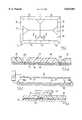
- FIG. 1is a plan view of a single tile constructed in accordance with the present invention, made of a plurality of pieces which are joined together,
- FIG. 2is a cross-sectional elevation, on an enlarged scale, through part of the tile taken along line II--II of FIG. 1, showing, schematically, the join between two adjacent pieces,
- FIG. 3shows a dielectric heating device for making the tile of FIG. 1,
- FIG. 4shows, in greater detail, the design of part of one electrode of the device of FIG. 3.
- each tile 9is made of three sets of pieces 10, 11 and 12.
- Each set of pieces (10, 11 or 12)comprises four identically shaped pieces. All the pieces for each set are cut from a large sheet of plastics material approximately 1 meter wide.
- the sheet of materialcomprises laminations consisting of a top translucent PVC wear layer 14 approximately 1.0 mm thick which is bonded to a thin PVC film 15 which is printed with a woodgrain effect with a coloured background.
- the film 15is bonded to a white PVC background layer 16 which has the effect of lightening the coloured background of the film 15.
- the white layer 16is bonded to a black PVC backing layer 17.
- the bonding of the layersis achieved by laying up the layers 14, 15, 16 and 17 and heat bonding them under pressure to produce a laminated sheet that is about 2.5 mm thick.
- each set of pieces 10, 11 or 12are of identical size and shape and are cut from a large sheet of the material, the wood grain effect varies from one piece to another, despite the fact that the wood grain effect pattern is repeated on the large sheet from which the pieces are cut. Furthermore, because the pieces of each set are identical and symmetrical, even if, against the odds, the pattern were the same on a number of identically shaped pieces of any set, it is highly unlikely that one would produce two tiles with exactly the same woodgrain effects on all the pieces of two or more tiles. Accordingly, by assembling the sets of pieces 10, 11 and 12 to make a tile it is possible to achieve a totally random effect.
- Each of the piecesis cut from the larger sheet of material using a tool which is described in our International Patent Application No. PCT/GB92/02115.
- Each piecehas a chamfered edge 20 in its upper region in which the chamfer is approximately 45° and extends to a depth not deeper than the film 15.
- each of the three sets 10, 11 and 12are assembled by abutting the edges of the pieces over lower regions thereof to make a precursor tile measuring 300 ⁇ 300 mm, and one or more of such tile precursors are held in a dielectric heating welding machine shown schematically in FIG. 3 which consists of a metal base 18 having rims 18a and a metal top member 19.
- the top member 19has projections 21 which define a pattern of shapes identical to the pieces of the sets 10, 11 and 12 and effectively defines weld lines corresponding to the abutting edges between the pieces 10, 11 and 12.
- the base 18 and top member 19effectively constitute the electrodes of a radio frequency dielectric heating unit.
- the power supply to the electrodes 18 and 19is taken from a 15Kw, 29Ka power supply unit running at a frequency of 27 MHz and automatically adjusts the voltage level to maintain correct dielectric heating of the layers to be welded.
- the base 18 and top member 19are preheated to a temperature between 40° C. and 100° C. by means of water-heated heat exchangers (not shown) in contact with the base 18 and the top member 19. Heating the base 18 and top member 19 also has a beneficial effect by imparting some heat into the region to be welded but not sufficient heat to damage the wear layer 14 of the tile.
- the projections 21 on the top electrode 19are of a smaller included angle than that defined by the two chamfered edges 20 of the abutting pieces (which is about 136°).
- the semi-angle of the recess created by the edges 20should be greater than the semi-angle of the projection.
- a semi-angle of the recess exceeding 45° (e.g. 68°) and a semi-angle of the projection of not more than 45°is preferred.
- the top electrode 19By providing the top electrode 19 with a sharp point at the tip of the projections 21, the shortest path for the electrical field generated during dielectric welding will be vertically through the tile between the member 19 and the base 18. This ensures that only a minimum amount of the tile is heated when the pieces are welded together and avoids disfiguring damage to the exposed upper surface of the tile. This lack of damage is made possible by the fact that the pieces are chamfered or recessed downwardly from the top surface.
- the base member 18can have two adjustable rims 18a whereby after laying the twelve pieces 10, 11 and 12 onto the base member in the required array (e.g. as shown in FIG. 1) the rims 18a are moved to close the pieces together to form the rectangular configuration shown with confronting edges in lower regions of the pieces in abutment.
- the electrode 19is lowered into contact with the assembled pieces and an electrical current at a frequency of 27 MHz is applied through the base 18 and electrode 19 to generate dielectric heating and melt and thereby fuse, or weld, only the lower regions (that is to say the layers 15, 16 and 17) to form a unitary tile. In this way all of the pieces are butt welded together along welded joints extending around the various pieces.
- the weldingcan also be carried out from the underside of the table, that is to say from the backing layer 17 side of the tile.
- the piecesare laid on the base of the jig with the translucent layer 14 facing the base and the top member 19 is brought down against the backing layer 17 to melt and fuse the abutting edges of the layers 15, 16 and 17.
- the base 18 of the jigwould have protrusions (similar in shape and size to the protrusions 20) that fit in the "V" shape defined by the chamfered edges of the pieces 10, 11 and 12 as shown in FIG. 4. It is much more difficult to assemble the pieces on a base plate 18 which has projections corresponding to the seam lines because each piece has to locate perfectly in the recesses formed by the raised projections. However there may be instances where it is advantageous to concentrate the electric field on the back surface of the tile.
- An essential requirement of layers to be welded together in accordance with the dielectric heating embodiment of the present inventionis that they are susceptible to absorption of electromagnetic energy by the dielectric effect. Almost all solid non-conductive plastics will absorb energy by dielectric heating to a certain extent. Some plastics such as polyethylene and polystyrene for example have relatively low dielectric heat absorption characteristics; these are often said to have a low "loss factor”. On the other hand PVC has a relatively high "loss factor” and will absorb electromagnetic energy by the dielectric effect. Therefore if one wishes to use a low "loss-factor" plastic as the backing layer one will need to modify its characteristics to increase its "loss-factor" by the addition or alloying of particles or other polymers.
- the method of joiningis achieved using a dielectric heating method.
- Other forms of weldingsuch as, for example, ultrasonic welding, or heat bonding using heated platens which are pressed into contact with the lower layers of the tile could be used for materials which will not absorb energy by dielectric heating.
- the joiningmay be done by adhesive bonding or by solvent bonding, although this is thought to be slightly more messy than the preferred welding methods.
- the present inventionis eminently suitable for making parquet type floor tiles with woodgrain patterning of the shapes shown in FIG. 1, the invention may be used to join assembled pieces of any shape and colour to make unitary tiles.
- the pieceshave an angled chamfer. It is to be understood that the top edge of each piece may be cut back with a vertical, rounded or other shaped edge which forms a small groove or recess in the top face of the tile at each join between pieces.
- a portable prefabricated unitary plastic tilehaving a top surface, a bottom surface, and an outer periphery, said outer periphery defining the plan area of said tile.
- the tile 9comprises at least a first plastic piece 11 having a first upper surface, a first lower surface, a first inclined surface 20 inclined to said first upper surface, and a first weld region adjacent said first inclined surface, and a second piece 12 comprising a second upper surface, a second lower surface, a second inclined surface 20 inclined to said second upper surface, and a second weld region adjacent said second inclined surface.
- the first and second weld regionsare welded together to form the unitary tile 9 by a weld joining the first and second tile pieces and forming a weld line.
- a grooveis provided on said top surface of the tile extending over said weld line, the groove being defined by said first and second inclined surfaces 20 which are unwelded to each other, the depth of said weld in the direction from said top surface to said bottom surface being less than the distance in that direction between said top surface and said bottom surface by the depth of said groove.
- the groove between the surfaces 20extends within said plan area of said tile.
- the said first and said second inclined surfacescomprise chamfered edges 20 to their respective tile pieces which are inclined relative to said upper surfaces of their respective piece by an angle of at least 45°, said groove comprising a V-shaped groove.
- the weldextends for the full depth of the thickness of that part of said tile that is beneath said groove.
- the lower surfaces of said first and second lower piecesare flat and contiguous, and the bottom surface of the tile is then flat.
- a colored layermay be provided between said backing layer and said printed layer.
- At least four distinct piecescan be provided, each with a different pattern, and with no two adjacent pieces having their patterns the same.
- the outer periphery of said tilecan be chamfered.
- At least one of said first and second piecescan be shaped non-rectangularly, and said plastic tile can be shaped rectangularly.
- a portable prefabricated unitary plastic floor tile 9having a peripheral edge and a plan area, said tile comprising a plurality of discrete plastic pieces 10, 11 and 12 which are shaped relative to each other and assembled together to abut edge to edge in lower regions of said pieces, said pieces being provided in upper regions of said pieces with groove-defining surfaces 20 adjacent their abutting edges and defining grooves extending parallel to, and above, said abutting edges; said pieces being welded together to form a unitary tile by a weld along said mutually abutting edges, said weld being below said grooves, with said groove-defining surfaces 20 being unwelded, and wherein at least some of said grooves extend away from said peripheral edge of said tile into the plan area of said tile.
- We also provide a method of forming a portable prefabricated unitary plastic tilecomprising taking a plurality of discrete pieces 10, 11 and 12 of plastic material each of which has an upper surface, a weld region, and an inclined surface inclined relative to its upper surface; placing said plurality of pieces adjacent each other to form a precursor of said unitary tile, and so that where two pieces abut, they do so along respective weld surfaces, and so that said pieces have their respective inclined surfaces forming a groove extending over said weld surfaces; and welding said weld surfaces of said pieces together so as to leave unwelded oppositely facing inclined surfaces 20 defining said groove, with said grooves extending away from a peripheral edge of said tile into the plan area defined by the outer periphery of said tile.
- the welding stepcan be carried out by dielectric heating of the pieces in the vicinity of the mutually abutting weld regions, and said pieces can be cut from a sheet stock having a pattern visible from its upper surface, and wherein a plurality of pieces of the same shape but with out-of-register patterns are provided so that each piece does not have the same appearance, and wherein the pieces may be assembled to form the precursor of the unitary tile in a plurality of different ways so that there is a reduced probability of producing two tiles of identical appearance from sheet stock.
- the welding stepis carried out with the use of a welding jig in which the shaped pieces are assembled in a rimmed base member of the jig and are conjoined by welding along mutually abutting edges through dielectric heating of the pieces between the base member and a top electrode, which top electrode has projections entering said grooves formed along said mutually abutting weld regions.
- the recessesmay have a semi-angle greater than 45° and said projection may have a semi-angle of not more than 45°.
- the welding jigmay have a base member with at least one adjustable rim which can be used to close the weld regions of the pieces together prior to welding. The join can be effected by ultrasonic or by solvent welding.
Landscapes
- Engineering & Computer Science (AREA)
- Mechanical Engineering (AREA)
- Architecture (AREA)
- Civil Engineering (AREA)
- Structural Engineering (AREA)
- Floor Finish (AREA)
Abstract
Description
Claims (23)
Priority Applications (1)
| Application Number | Priority Date | Filing Date | Title |
|---|---|---|---|
| US08/787,890US5834081A (en) | 1991-12-30 | 1997-01-23 | Tiles, method of manufacturing tiles from plastic material and equipment for facilitating such manufacture |
Applications Claiming Priority (4)
| Application Number | Priority Date | Filing Date | Title |
|---|---|---|---|
| GB9127473AGB9127473D0 (en) | 1991-12-30 | 1991-12-30 | Tiles |
| GB9127473 | 1991-12-30 | ||
| US25617894A | 1994-06-28 | 1994-06-28 | |
| US08/787,890US5834081A (en) | 1991-12-30 | 1997-01-23 | Tiles, method of manufacturing tiles from plastic material and equipment for facilitating such manufacture |
Related Parent Applications (1)
| Application Number | Title | Priority Date | Filing Date |
|---|---|---|---|
| US25617894AContinuation | 1991-12-30 | 1994-06-28 |
Publications (1)
| Publication Number | Publication Date |
|---|---|
| US5834081Atrue US5834081A (en) | 1998-11-10 |
Family
ID=26300085
Family Applications (1)
| Application Number | Title | Priority Date | Filing Date |
|---|---|---|---|
| US08/787,890Expired - LifetimeUS5834081A (en) | 1991-12-30 | 1997-01-23 | Tiles, method of manufacturing tiles from plastic material and equipment for facilitating such manufacture |
Country Status (1)
| Country | Link |
|---|---|
| US (1) | US5834081A (en) |
Cited By (26)
| Publication number | Priority date | Publication date | Assignee | Title |
|---|---|---|---|---|
| US6027599A (en)* | 1997-01-30 | 2000-02-22 | Wang; Wen-Lung | Method for manufacturing knockdown safety soft floor tile |
| US20030168770A1 (en)* | 2002-01-17 | 2003-09-11 | Charles Young | Method of manufacturing footprint tiles |
| US6694682B2 (en)* | 2000-03-09 | 2004-02-24 | The Amtico Company Limited | Multicomponent tiles and a method for manufacturing multicomponent tiles |
| US6722093B2 (en)* | 2002-01-28 | 2004-04-20 | Gerard Dauplay | Bamboo tile and method for manufacturing the same |
| US6773527B2 (en) | 2002-04-01 | 2004-08-10 | Kimberly-Clark Worldwide, Inc. | Method for obtaining improved ultrasonic bond strength |
| US6786019B2 (en)* | 2000-06-13 | 2004-09-07 | Flooring Industries, Ltd. | Floor covering |
| US20040255541A1 (en)* | 2003-06-04 | 2004-12-23 | Thiers Bernard Paul Joseph | Floor panel and method for manufacturing such floor panels |
| US20100117310A1 (en)* | 2008-11-07 | 2010-05-13 | Saint-Gobain Performance Plastics Corporation | Large diameter thermoplastic seal |
| US20100116422A1 (en)* | 2008-11-07 | 2010-05-13 | Saint-Gobain Performance Plastics Corporation | Method of forming large diameter thermoplastic seal |
| US20110107720A1 (en)* | 2003-08-11 | 2011-05-12 | Interface, Inc. | Carpet tiles and carpet tile installations |
| US20110203213A1 (en)* | 2010-02-19 | 2011-08-25 | Paata Dzigava | Flooring devices, systems, and methods thereof |
| US8176698B2 (en)* | 2003-10-11 | 2012-05-15 | Kronotec Ag | Panel |
| US8220221B2 (en) | 2002-08-15 | 2012-07-17 | Interface, Inc. | System and method for floor covering installation |
| US8381473B2 (en) | 2000-09-19 | 2013-02-26 | Interface, Inc. | System and method for floor covering installation |
| US20130326989A1 (en)* | 2012-06-08 | 2013-12-12 | Ian David Hartert | Wooden Floor Tile With Milled Surface |
| US9180575B1 (en) | 2010-11-16 | 2015-11-10 | Paata Dzigava | Systems and methods for constructing mosaic wood flooring panels and/or more complex mosaic wood structures |
| US9206827B2 (en) | 2012-11-20 | 2015-12-08 | Avery Dennison Corporation | Wall mount organization system |
| US9691240B2 (en) | 2015-01-22 | 2017-06-27 | Interface, Inc. | Floor covering system with sensors |
| US9988760B2 (en) | 2011-05-04 | 2018-06-05 | Tandus Centiva Inc. | Modular carpet systems |
| US10093069B2 (en) | 2012-05-23 | 2018-10-09 | Saint-Gobain Performance Plastics Corporation | Method of forming large diameter thermoplastic seal |
| US10450760B2 (en) | 2006-01-12 | 2019-10-22 | Valinge Innovation Ab | Floorboards comprising a decorative edge part in a resilient surface layer |
| US10486399B2 (en) | 1999-12-14 | 2019-11-26 | Valinge Innovation Ab | Thermoplastic planks and methods for making the same |
| US10738482B2 (en) | 2009-06-12 | 2020-08-11 | I4F Licensing Nv | Floor panel and floor covering consisting of a plurality of such floor panels |
| US10947741B2 (en) | 2017-04-26 | 2021-03-16 | I4F Licensing Nv | Panel and covering |
| US10975580B2 (en) | 2001-07-27 | 2021-04-13 | Valinge Innovation Ab | Floor panel with sealing means |
| US12330377B2 (en)* | 2023-03-01 | 2025-06-17 | Richard Bushey | Method for fabricating a wrap around furniture glide |
Citations (12)
| Publication number | Priority date | Publication date | Assignee | Title |
|---|---|---|---|---|
| US2108226A (en)* | 1936-01-06 | 1938-02-15 | Tile Tex Company | Composition tile |
| US2841004A (en)* | 1952-08-21 | 1958-07-01 | Maccaferri Mario | Self-sealing wall tiles |
| US3056235A (en)* | 1951-10-31 | 1962-10-02 | Paul W Makray | Wall tile |
| US3647587A (en)* | 1969-06-23 | 1972-03-07 | Burlington Industries Inc | Method of installing invisible seams |
| US3897296A (en)* | 1973-07-12 | 1975-07-29 | Amchem Prod | Thermal welding of plastic |
| US4405539A (en)* | 1980-11-15 | 1983-09-20 | Dynamit Nobel Aktiengesellschaft | Process for the production of patterned tiles from thermoplastic synthetic resins |
| US4678528A (en)* | 1985-03-05 | 1987-07-07 | American Biltrite, Inc. | Method and apparatus for making a printed and embossed floor covering using a cast wear layer |
| US4738247A (en)* | 1984-11-01 | 1988-04-19 | Moore Barrie P | Roof installations |
| US4828896A (en)* | 1986-12-01 | 1989-05-09 | Courtaulds Plc | Patterned thermoplastics tile and method of making same |
| US4904513A (en)* | 1987-11-13 | 1990-02-27 | Elide De Nicolo | Composite panes of glass for window-frames and door-frames |
| US5098760A (en)* | 1990-12-21 | 1992-03-24 | Stained Glass Overlay, Inc. | Beveled glass panel and method of making |
| US5370368A (en)* | 1993-06-28 | 1994-12-06 | Terrels; Andrew P. | Handrail assembly |
- 1997
- 1997-01-23USUS08/787,890patent/US5834081A/ennot_activeExpired - Lifetime
Patent Citations (12)
| Publication number | Priority date | Publication date | Assignee | Title |
|---|---|---|---|---|
| US2108226A (en)* | 1936-01-06 | 1938-02-15 | Tile Tex Company | Composition tile |
| US3056235A (en)* | 1951-10-31 | 1962-10-02 | Paul W Makray | Wall tile |
| US2841004A (en)* | 1952-08-21 | 1958-07-01 | Maccaferri Mario | Self-sealing wall tiles |
| US3647587A (en)* | 1969-06-23 | 1972-03-07 | Burlington Industries Inc | Method of installing invisible seams |
| US3897296A (en)* | 1973-07-12 | 1975-07-29 | Amchem Prod | Thermal welding of plastic |
| US4405539A (en)* | 1980-11-15 | 1983-09-20 | Dynamit Nobel Aktiengesellschaft | Process for the production of patterned tiles from thermoplastic synthetic resins |
| US4738247A (en)* | 1984-11-01 | 1988-04-19 | Moore Barrie P | Roof installations |
| US4678528A (en)* | 1985-03-05 | 1987-07-07 | American Biltrite, Inc. | Method and apparatus for making a printed and embossed floor covering using a cast wear layer |
| US4828896A (en)* | 1986-12-01 | 1989-05-09 | Courtaulds Plc | Patterned thermoplastics tile and method of making same |
| US4904513A (en)* | 1987-11-13 | 1990-02-27 | Elide De Nicolo | Composite panes of glass for window-frames and door-frames |
| US5098760A (en)* | 1990-12-21 | 1992-03-24 | Stained Glass Overlay, Inc. | Beveled glass panel and method of making |
| US5370368A (en)* | 1993-06-28 | 1994-12-06 | Terrels; Andrew P. | Handrail assembly |
Cited By (57)
| Publication number | Priority date | Publication date | Assignee | Title |
|---|---|---|---|---|
| US6027599A (en)* | 1997-01-30 | 2000-02-22 | Wang; Wen-Lung | Method for manufacturing knockdown safety soft floor tile |
| US10486399B2 (en) | 1999-12-14 | 2019-11-26 | Valinge Innovation Ab | Thermoplastic planks and methods for making the same |
| US20040151863A1 (en)* | 2000-03-09 | 2004-08-05 | The Amtico Company Limited | Multicomponent tiles and a method for manufacturing multicomponent tiles |
| US6694682B2 (en)* | 2000-03-09 | 2004-02-24 | The Amtico Company Limited | Multicomponent tiles and a method for manufacturing multicomponent tiles |
| US20060179776A1 (en)* | 2000-06-13 | 2006-08-17 | Flooring Industries Ltd. | Floor covering, floor panels for forming such floor covering, and method for realizing such floor panels |
| US7249445B2 (en) | 2000-06-13 | 2007-07-31 | Flooring Industries Ltd. | Floor covering, floor panels for forming such floor covering, and method of realizing such floor panels |
| US6786019B2 (en)* | 2000-06-13 | 2004-09-07 | Flooring Industries, Ltd. | Floor covering |
| US8535589B2 (en) | 2000-06-13 | 2013-09-17 | Flooring Industries Limited, Sarl | Floor covering, floor panels for forming such floor covering, and method for realizing such floor panels |
| US20050025934A1 (en)* | 2000-06-13 | 2005-02-03 | Flooring Industries Ltd. | Floor covering, floor panels for forming such floor covering, and method for realizing such floor panels |
| US6931811B2 (en) | 2000-06-13 | 2005-08-23 | Flooring Industries, Ltd. | Floor covering, floor panels for forming such floor covering, and method for realizing such floor panels |
| US7055290B2 (en) | 2000-06-13 | 2006-06-06 | Flooring Industries Ltd. | Floor covering, floor panels for forming such floor covering, and method for realizing such floor panels |
| US20060179774A1 (en)* | 2000-06-13 | 2006-08-17 | Flooring Industies Ltd. | Floor covering, floor panels for forming such floor covering, and method for realizing such floor panels |
| US9850669B2 (en) | 2000-06-13 | 2017-12-26 | Flooring Industries Limited, Sarl | Floor covering panel |
| US20060179775A1 (en)* | 2000-06-13 | 2006-08-17 | Flooring Industries Ltd. | Floor covering, floor panels for forming such floor covering, and method for realizing such floor panels |
| US20070051064A1 (en)* | 2000-06-13 | 2007-03-08 | Thiers Bernard P J | Floor covering, floor panels for forming such floor covering, and method of realizing such floor panels |
| US9951525B2 (en) | 2000-06-13 | 2018-04-24 | Flooring Industries Limited, Sarl | Floor covering panel |
| US7632561B2 (en) | 2000-06-13 | 2009-12-15 | Flooring Industries Limited, Sarl | Laminate floor covering panel having wood pattern |
| US20100313511A1 (en)* | 2000-06-13 | 2010-12-16 | Bernard Paul Joseph Thiers | Floor covering panel |
| US9970198B2 (en) | 2000-06-13 | 2018-05-15 | Flooring Industries Limited, Sarl | Floor covering, floor panels for forming such floor covering, and method for realizing such floor panels |
| US7842212B2 (en) | 2000-06-13 | 2010-11-30 | Flooring Industries Limited, Sarl | Floor covering, floor panels for forming such floor covering, and method for realizing such floor panels |
| US9402496B2 (en) | 2000-09-19 | 2016-08-02 | Interface, Inc. | System for modular tile installation |
| US8381473B2 (en) | 2000-09-19 | 2013-02-26 | Interface, Inc. | System and method for floor covering installation |
| US8434282B2 (en) | 2000-09-19 | 2013-05-07 | Interface, Inc. | System for carpet tile installation |
| US10975580B2 (en) | 2001-07-27 | 2021-04-13 | Valinge Innovation Ab | Floor panel with sealing means |
| US20030168770A1 (en)* | 2002-01-17 | 2003-09-11 | Charles Young | Method of manufacturing footprint tiles |
| US6722093B2 (en)* | 2002-01-28 | 2004-04-20 | Gerard Dauplay | Bamboo tile and method for manufacturing the same |
| US6773527B2 (en) | 2002-04-01 | 2004-08-10 | Kimberly-Clark Worldwide, Inc. | Method for obtaining improved ultrasonic bond strength |
| US8468771B2 (en)* | 2002-08-15 | 2013-06-25 | Interface, Inc. | System and method for floor covering installation |
| US9085902B2 (en) | 2002-08-15 | 2015-07-21 | Interface, Inc. | Methods for installing modular tiles on a flooring surface |
| US8220221B2 (en) | 2002-08-15 | 2012-07-17 | Interface, Inc. | System and method for floor covering installation |
| US20040255541A1 (en)* | 2003-06-04 | 2004-12-23 | Thiers Bernard Paul Joseph | Floor panel and method for manufacturing such floor panels |
| US8468772B2 (en) | 2003-08-11 | 2013-06-25 | Interface, Inc. | Carpet tiles and carpet tile installations |
| US20110107720A1 (en)* | 2003-08-11 | 2011-05-12 | Interface, Inc. | Carpet tiles and carpet tile installations |
| US8176698B2 (en)* | 2003-10-11 | 2012-05-15 | Kronotec Ag | Panel |
| US11702847B2 (en) | 2006-01-12 | 2023-07-18 | Valinge Innovation Ab | Floorboards comprising a decorative edge part in a resilient surface layer |
| US10450760B2 (en) | 2006-01-12 | 2019-10-22 | Valinge Innovation Ab | Floorboards comprising a decorative edge part in a resilient surface layer |
| US11066836B2 (en) | 2006-01-12 | 2021-07-20 | Valinge Innovation Ab | Floorboards comprising a decorative edge part in a resilient surface layer |
| US20100116422A1 (en)* | 2008-11-07 | 2010-05-13 | Saint-Gobain Performance Plastics Corporation | Method of forming large diameter thermoplastic seal |
| US20100117310A1 (en)* | 2008-11-07 | 2010-05-13 | Saint-Gobain Performance Plastics Corporation | Large diameter thermoplastic seal |
| US8721823B2 (en) | 2008-11-07 | 2014-05-13 | Saint-Gobain Performance Plastics Corporation | Method of forming large diameter thermoplastic seal |
| US9702462B2 (en) | 2008-11-07 | 2017-07-11 | Saint-Gobain Performance Plastics Corporation | Large diameter thermoplastic seal |
| US10738481B2 (en) | 2009-06-12 | 2020-08-11 | I4F Licensing Nv | Floor panel and floor covering consisting of a plurality of such floor panels |
| US11668100B2 (en) | 2009-06-12 | 2023-06-06 | I4F Licensing Nv | Floor panel and floor covering consisting of a plurality of such floor panels |
| US10738480B2 (en) | 2009-06-12 | 2020-08-11 | I4F Licensing Nv | Floor panel and floor covering consisting of a plurality of such floor panels |
| US10738482B2 (en) | 2009-06-12 | 2020-08-11 | I4F Licensing Nv | Floor panel and floor covering consisting of a plurality of such floor panels |
| US20110203213A1 (en)* | 2010-02-19 | 2011-08-25 | Paata Dzigava | Flooring devices, systems, and methods thereof |
| US8869481B2 (en) | 2010-02-19 | 2014-10-28 | Paata Dzigava | Flooring devices, systems, and methods thereof |
| US9180575B1 (en) | 2010-11-16 | 2015-11-10 | Paata Dzigava | Systems and methods for constructing mosaic wood flooring panels and/or more complex mosaic wood structures |
| US9988760B2 (en) | 2011-05-04 | 2018-06-05 | Tandus Centiva Inc. | Modular carpet systems |
| US10093069B2 (en) | 2012-05-23 | 2018-10-09 | Saint-Gobain Performance Plastics Corporation | Method of forming large diameter thermoplastic seal |
| US20130326989A1 (en)* | 2012-06-08 | 2013-12-12 | Ian David Hartert | Wooden Floor Tile With Milled Surface |
| US10231556B2 (en) | 2012-11-20 | 2019-03-19 | Ccl Label, Inc. | Wall mount organization system |
| US9206827B2 (en) | 2012-11-20 | 2015-12-08 | Avery Dennison Corporation | Wall mount organization system |
| US9691240B2 (en) | 2015-01-22 | 2017-06-27 | Interface, Inc. | Floor covering system with sensors |
| US10947741B2 (en) | 2017-04-26 | 2021-03-16 | I4F Licensing Nv | Panel and covering |
| US11441319B2 (en) | 2017-04-26 | 2022-09-13 | I4F Licensing Nv | Panel and covering |
| US12330377B2 (en)* | 2023-03-01 | 2025-06-17 | Richard Bushey | Method for fabricating a wrap around furniture glide |
Similar Documents
| Publication | Publication Date | Title |
|---|---|---|
| US5834081A (en) | Tiles, method of manufacturing tiles from plastic material and equipment for facilitating such manufacture | |
| US11208813B2 (en) | Floor panel, as well as method, device and accessories for manufacturing such floor panel | |
| US5322584A (en) | Method for making wooden tile | |
| CA1296069C (en) | Laser-cut patterned thermoplastics and method for making same | |
| US3075862A (en) | Cover panels and method of manufacture | |
| EP0620885B1 (en) | Tiles, method of manufacturing tiles from plastic material and equipment for facilitating such manufacture | |
| WO1993013281A9 (en) | Tiles, method of manufacturing tiles from plastic material and equipment for facilitating such manufacture | |
| JPS63149137A (en) | Plastic tile and manufacture thereof | |
| CA2218922A1 (en) | Process for producing artificial marble having striped pattern | |
| EP0942823B1 (en) | Apparatus for radio-frequency bonding of thermoplastic members | |
| JPH0259320A (en) | Manufacture of synthetic resin molded display plate | |
| JP2020159081A (en) | Wrapping decorative sheet | |
| JPH0562089B2 (en) | ||
| JPS625051B2 (en) | ||
| JPH0442159B2 (en) | ||
| JPH04368900A (en) | decorative embossed sheet | |
| JPS5511827A (en) | Method of manufacturing decorating material made of synthetic resin | |
| JPH07197590A (en) | Floor board of parquetry workmanship and manufacture thereof | |
| JPH04292488A (en) | Aerated concrete plate with uneven pattern and method for manufacturing the same | |
| KR100291981B1 (en) | Curved multi-layer flooring for cookers and apparatus for manufacturing same | |
| JPS62920Y2 (en) | ||
| KR20240065702A (en) | Paper tray coated with coating liquid that can be usded under high temperature conditions | |
| JPS6477518A (en) | Method for laminating thermoplastic resin member | |
| JPH06270256A (en) | Lattice like structure, and method and apparatus for producing same | |
| JPS634118Y2 (en) |
Legal Events
| Date | Code | Title | Description |
|---|---|---|---|
| FEPP | Fee payment procedure | Free format text:PAYOR NUMBER ASSIGNED (ORIGINAL EVENT CODE: ASPN); ENTITY STATUS OF PATENT OWNER: SMALL ENTITY | |
| AS | Assignment | Owner name:AMTICO COMPANY LIMITED, THE, UNITED KINGDOM Free format text:ASSIGNMENT OF ASSIGNORS INTEREST;ASSIGNOR:FANTI, LUIGI;REEL/FRAME:009416/0562 Effective date:19940527 | |
| STCF | Information on status: patent grant | Free format text:PATENTED CASE | |
| REMI | Maintenance fee reminder mailed | ||
| FPAY | Fee payment | Year of fee payment:4 | |
| SULP | Surcharge for late payment | ||
| FPAY | Fee payment | Year of fee payment:8 | |
| FPAY | Fee payment | Year of fee payment:12 | |
| AS | Assignment | Owner name:BANK OF AMERICA, N.A., AS AGENT, NEW YORK Free format text:THE AMTICO COMPANY LIMITED PATENT SECURITY AGREEMENT;ASSIGNOR:THE AMTICO COMPANY LIMITED;REEL/FRAME:027831/0005 Effective date:20120305 | |
| AS | Assignment | Owner name:TPG SPECIALTY LENDING, INC., AS AGENT, NEW YORK Free format text:PATENT SECURITY AGREEMENT;ASSIGNOR:THE AMITCO COMPANY LIMITED;REEL/FRAME:027839/0312 Effective date:20120305 | |
| AS | Assignment | Owner name:THE AMTICO COMPANY LIMITED, CALIFORNIA Free format text:RELEASE BY SECURED PARTY;ASSIGNOR:TPG SPECIALITY LENDING, INC.;REEL/FRAME:033901/0352 Effective date:20141001 | |
| AS | Assignment | Owner name:THE AMTICO COMPANY LIMITED, CALIFORNIA Free format text:RELEASE OF SECURITY INTEREST IN PATENTS;ASSIGNOR:BANK OF AMERICA, N.A., AS AGENT;REEL/FRAME:035108/0797 Effective date:20150227 |