US5833714A - Cochlear electrode array employing tantalum metal - Google Patents
Cochlear electrode array employing tantalum metalDownload PDFInfo
- Publication number
- US5833714A US5833714AUS08/784,209US78420997AUS5833714AUS 5833714 AUS5833714 AUS 5833714AUS 78420997 AUS78420997 AUS 78420997AUS 5833714 AUS5833714 AUS 5833714A
- Authority
- US
- United States
- Prior art keywords
- tantalum
- feedthrough
- noble metal
- stimulus
- electrode
- Prior art date
- Legal status (The legal status is an assumption and is not a legal conclusion. Google has not performed a legal analysis and makes no representation as to the accuracy of the status listed.)
- Expired - Fee Related
Links
- GUVRBAGPIYLISA-UHFFFAOYSA-Ntantalum atomChemical compound[Ta]GUVRBAGPIYLISA-UHFFFAOYSA-N0.000titleclaimsabstractdescription72
- 229910052715tantalumInorganic materials0.000claimsabstractdescription57
- 229910000510noble metalInorganic materials0.000claimsabstractdescription31
- 230000000638stimulationEffects0.000claimsabstractdescription27
- 150000002503iridiumChemical class0.000claimsabstractdescription14
- 239000003990capacitorSubstances0.000claimsabstractdescription11
- 239000012530fluidSubstances0.000claimsabstractdescription10
- BPUBBGLMJRNUCC-UHFFFAOYSA-Noxygen(2-);tantalum(5+)Chemical compound[O-2].[O-2].[O-2].[O-2].[O-2].[Ta+5].[Ta+5]BPUBBGLMJRNUCC-UHFFFAOYSA-N0.000claimsabstractdescription10
- BASFCYQUMIYNBI-UHFFFAOYSA-NplatinumChemical compound[Pt]BASFCYQUMIYNBI-UHFFFAOYSA-N0.000claimsabstractdescription10
- PBCFLUZVCVVTBY-UHFFFAOYSA-Ntantalum pentoxideInorganic materialsO=[Ta](=O)O[Ta](=O)=OPBCFLUZVCVVTBY-UHFFFAOYSA-N0.000claimsabstractdescription10
- 230000008878couplingEffects0.000claimsabstractdescription5
- 238000010168coupling processMethods0.000claimsabstractdescription5
- 238000005859coupling reactionMethods0.000claimsabstractdescription5
- 229910052697platinumInorganic materials0.000claimsabstractdescription5
- 230000002051biphasic effectEffects0.000claimsdescription22
- 229910052741iridiumInorganic materials0.000claimsdescription15
- GKOZUEZYRPOHIO-UHFFFAOYSA-Niridium atomChemical compound[Ir]GKOZUEZYRPOHIO-UHFFFAOYSA-N0.000claimsdescription15
- 230000010287polarizationEffects0.000claimsdescription14
- 210000001124body fluidAnatomy0.000claimsdescription5
- 239000010839body fluidSubstances0.000claimsdescription5
- 238000007599dischargingMethods0.000claimsdescription2
- FAPWRFPIFSIZLT-UHFFFAOYSA-MSodium chlorideChemical compound[Na+].[Cl-]FAPWRFPIFSIZLT-UHFFFAOYSA-M0.000abstractdescription13
- 239000011780sodium chlorideSubstances0.000abstractdescription13
- 238000007743anodisingMethods0.000abstractdescription5
- 210000003477cochleaAnatomy0.000abstractdescription4
- 239000007943implantSubstances0.000abstractdescription3
- 229910001936tantalum oxideInorganic materials0.000abstractdescription3
- 210000001519tissueAnatomy0.000description11
- 230000004936stimulating effectEffects0.000description10
- 239000010410layerSubstances0.000description7
- 239000004020conductorSubstances0.000description6
- 238000002048anodisation reactionMethods0.000description5
- 229910052751metalInorganic materials0.000description5
- 239000002184metalSubstances0.000description5
- 238000000034methodMethods0.000description5
- 239000004809TeflonSubstances0.000description4
- 229920006362Teflon®Polymers0.000description4
- 230000001276controlling effectEffects0.000description4
- 238000013461designMethods0.000description4
- 239000003989dielectric materialSubstances0.000description4
- 238000004519manufacturing processMethods0.000description4
- 229920001296polysiloxanePolymers0.000description4
- 230000008569processEffects0.000description4
- 210000001323spiral ganglionAnatomy0.000description4
- 238000003491arrayMethods0.000description3
- 210000004027cellAnatomy0.000description3
- 239000000919ceramicSubstances0.000description3
- 238000000576coating methodMethods0.000description3
- 238000010586diagramMethods0.000description3
- 238000000465mouldingMethods0.000description3
- 230000002265preventionEffects0.000description3
- 230000008901benefitEffects0.000description2
- 230000015572biosynthetic processEffects0.000description2
- 210000000988bone and boneAnatomy0.000description2
- 210000000860cochlear nerveAnatomy0.000description2
- 230000007547defectEffects0.000description2
- 210000001787dendriteAnatomy0.000description2
- 230000000694effectsEffects0.000description2
- 239000003792electrolyteSubstances0.000description2
- 238000001125extrusionMethods0.000description2
- 238000009413insulationMethods0.000description2
- 239000000463materialSubstances0.000description2
- 210000002569neuronAnatomy0.000description2
- 230000007935neutral effectEffects0.000description2
- 210000001079scala tympaniAnatomy0.000description2
- XLYOFNOQVPJJNP-UHFFFAOYSA-NwaterChemical compoundOXLYOFNOQVPJJNP-UHFFFAOYSA-N0.000description2
- ROSDCCJGGBNDNL-UHFFFAOYSA-N[Ta].[Pb]Chemical compound[Ta].[Pb]ROSDCCJGGBNDNL-UHFFFAOYSA-N0.000description1
- 229910045601alloyInorganic materials0.000description1
- 239000000956alloySubstances0.000description1
- 230000003466anti-cipated effectEffects0.000description1
- 230000000712assemblyEffects0.000description1
- 238000000429assemblyMethods0.000description1
- 230000003376axonal effectEffects0.000description1
- 230000000903blocking effectEffects0.000description1
- 210000005056cell bodyAnatomy0.000description1
- 239000011248coating agentSubstances0.000description1
- 230000010485copingEffects0.000description1
- 230000007797corrosionEffects0.000description1
- 238000005260corrosionMethods0.000description1
- 230000000593degrading effectEffects0.000description1
- 238000011161developmentMethods0.000description1
- HTXDPTMKBJXEOW-UHFFFAOYSA-NdioxoiridiumChemical compoundO=[Ir]=OHTXDPTMKBJXEOW-UHFFFAOYSA-N0.000description1
- 238000005868electrolysis reactionMethods0.000description1
- 239000008393encapsulating agentSubstances0.000description1
- 239000011521glassSubstances0.000description1
- 210000001753habenulaAnatomy0.000description1
- 238000002513implantationMethods0.000description1
- 239000012535impuritySubstances0.000description1
- 238000002347injectionMethods0.000description1
- 239000007924injectionSubstances0.000description1
- 238000003780insertionMethods0.000description1
- 230000037431insertionEffects0.000description1
- 150000002500ionsChemical class0.000description1
- 229910000457iridium oxideInorganic materials0.000description1
- 239000007788liquidSubstances0.000description1
- 229940127554medical productDrugs0.000description1
- 239000000155meltSubstances0.000description1
- 238000012986modificationMethods0.000description1
- 230000004048modificationEffects0.000description1
- 230000008904neural responseEffects0.000description1
- 230000003204osmotic effectEffects0.000description1
- 238000004806packaging method and processMethods0.000description1
- 230000002035prolonged effectEffects0.000description1
- 230000001105regulatory effectEffects0.000description1
- 230000000284resting effectEffects0.000description1
- 238000007789sealingMethods0.000description1
- 229920002379silicone rubberPolymers0.000description1
- 239000002344surface layerSubstances0.000description1
- 230000004083survival effectEffects0.000description1
- 238000003466weldingMethods0.000description1
Images


Classifications
- A—HUMAN NECESSITIES
- A61—MEDICAL OR VETERINARY SCIENCE; HYGIENE
- A61N—ELECTROTHERAPY; MAGNETOTHERAPY; RADIATION THERAPY; ULTRASOUND THERAPY
- A61N1/00—Electrotherapy; Circuits therefor
- A61N1/02—Details
- A61N1/04—Electrodes
- A61N1/05—Electrodes for implantation or insertion into the body, e.g. heart electrode
- A61N1/0526—Head electrodes
- A61N1/0541—Cochlear electrodes
- A—HUMAN NECESSITIES
- A61—MEDICAL OR VETERINARY SCIENCE; HYGIENE
- A61N—ELECTROTHERAPY; MAGNETOTHERAPY; RADIATION THERAPY; ULTRASOUND THERAPY
- A61N1/00—Electrotherapy; Circuits therefor
- A61N1/18—Applying electric currents by contact electrodes
- A61N1/32—Applying electric currents by contact electrodes alternating or intermittent currents
- A61N1/36—Applying electric currents by contact electrodes alternating or intermittent currents for stimulation
- A61N1/36036—Applying electric currents by contact electrodes alternating or intermittent currents for stimulation of the outer, middle or inner ear
- A61N1/36038—Cochlear stimulation
Definitions
- the present inventionrelates to implantable stimulation devices, e.g., cochlear prostheses used to electrically stimulate the auditory nerve, and more particularly to the electrodes or electrode contacts used with such implantable stimulating devices.
- implantable stimulation devicese.g., cochlear prostheses used to electrically stimulate the auditory nerve, and more particularly to the electrodes or electrode contacts used with such implantable stimulating devices.
- the above requirementsare usually met by employing metal electrode contacts, and connecting such electrode contacts to hermetically sealed electronic circuits via leads and feedthroughs into the hermetically sealed electronic package.
- the electrode contactstypically consist of the noble metal platinum and its alloys with iridium. This choice gives rise to the following design problems and strategies for coping with them:
- Electrostimal stimulation pulses having two opposite phases each with equal chargeare actively applied to each contact.
- pulsesare applied to one intracochlear contact with respect to an indifferent electrode usually located outside the cochlea, a configuration known as "monopolar.”
- monopolara configuration known as "monopolar.”
- pulsesmay be applied bipolarly between two or more intracochlear contacts.
- these actively driven biphasic pulsesrequire pulse-forming circuitry to produce two different polarities of voltage and current, either by operating in a push-pull configuration with both positive and negative power supply voltages or by employing switching networks in the output stages that can reverse the direction of current flow through the electrodes to which it is intermittently connected.
- capacitorsare incorporated in series with each intracochlear contact to block any net DC current that might arise through slight inequalities between the two opposite phases of the stimulation pulses.
- One disadvantage of such capacitorsis that they have a finite impedance, which is in series with the electrode impedance, and increases the voltage that must be provided by the output circuit in order to produce a given output current in the total load. This can be minimized by using a large capacitance value component, but such capacitors are physically bulky and one is required for each intracochlear electrode contact.
- blocking capacitorshave been omitted in favor of a passive discharge scheme which assumes that any residual charge will be trapped by and produce a small polarization of the intrinsic capacitance of the metal-electrolyte interface, which polarization can be bled off the capacitance by shorting the electrode pair together between pulses.
- the maximal permissible polarization that can accumulate safely on the metal-electrolyte interfaceis limited by the electromotive force required for the electrolysis of the saline body fluids, which is about ⁇ 0.8 VDC, a value that is far lower than the compliance voltage actually available to the electronic circuitry ( ⁇ 5 to ⁇ 15 VDC).
- the stimulus-generating circuitrycan easily produce conditions that are known to lead to electrolytic damage to both the electrodes and the surrounding tissue.
- Each of the intracochlear contactsgenerally requires a separate insulated wire from the stimulus generating circuitry to the contact itself. These fine wires must be bundled closely together in a highly flexible cable and they often sustain substantial handling during fabrication of the electrode array and cable. Because the electrodes themselves have substantial impedance, even small leaks in the insulation between individual wires and between a wire and the conductive body fluids surrounding the lead and the electrode may result in substantial shunting of output current away from the desired electrode contact, thereby degrading performance.
- the electronic circuitryis usually sealed into an enclosure made of ceramic and/or metal with hermetically sealed feedthroughs to each of the leads going to each of the electrodes.
- hermetically sealed feedthroughsto each of the leads going to each of the electrodes.
- the feedthroughs and the attachments to the wire leadsconstitutes one of the most vulnerable points for the development of electrical shunts. This is because water vapor that is present in polymeric encapsulants placed over these connection points outside the hermetic package tends to condense on the hydrophilic metal and/or ceramic surfaces of the package and the dielectrics that form part of the feedthrough assemblies. Condensed water tends to dissolve ions from these surfaces and enlarge in volume under osmotic pressure, forming conductive shunts between feedthroughs and leads.
- iridiumcan be electrochemically activated, resulting in a surface layer of iridium oxide that tends to float rapidly to neutral polarization regardless of changes in the polarization of the tantalum pentoxide (Loeb, et al., 1991).
- Tantalum metalis a metal of choice for the hermetic feedthroughs and wire leads because tantalum metal is strong, ductile, highly conductive, biocompatible, inexpensive and readily drawn into wire of any desired dimension. It spontaneously forms a native oxide that facilitates hermetic sealing to various glass and ceramic dielectrics commonly employed in hermetic feedthroughs. Use of anodized tantalum feedthroughs and wire leads with non-tantalum electrodes in an implantable electronic tissue stimulator was described by White, 1980 (Annals of Biomed. Engng. 8:317-332).
- the present inventionaddresses the above and other needs by providing an implant device that uses tantalum and tantalum pentoxide as a complete system for the conveyance of electrical stimulation pulses from stimulus-forming circuitry contained within an hermetic enclosure to the saline fluids of the cochlea (or other tissue to be stimulated).
- a preferred application for the present inventionis a cochlear prosthesis.
- Such prosthesiscomprises a multiplicity of electrode contacts made from sintered, anodized tantalum, connected via tantalum wire leads to tantalum feedthroughs into an hermetically sealed package containing stimulus pulse-forming electronic circuitry.
- One or more counterelectrode contactsare made from activated iridium, connected via platinum or other noble metal leads to noble metal feedthroughs.
- the stimulus generating circuitWhen powered-up, the stimulus generating circuit produces a steady polarizing potential of approximately half its maximum output voltage range, which potential is applied as a positive (anodizing) voltage to each tantalum electrode and associated lead and feedthrough, with respect to the activated iridium electrode(s), which act as the reference point for the circuit.
- the present inventionadvantageously eliminates the need for internal coupling capacitors without the usual danger of having DC current flow to the saline fluids. Further, the present invention eliminates the need for high integrity and adhesion in other dielectrics used to encapsulate the feedthroughs and wires outside the hermetic package en route to the cochlea (or other stimulation site).
- the present inventionWhen used with a counterelectrode made of activated iridium and stimulus-forming circuitry of a type described herein, the present invention increases the power efficiency, the available compliance voltage, and the reliability of such stimulus-forming circuitry. Moreover, the present invention simplifies the fabrication and improves the reliability of the electrode array and associated flexible cable connecting the array to the stimulus-forming circuitry.
- FIGS. 1A-1Ddiagrammatically depict various electrode arrays made in accordance with the present invention
- FIG. 1Eshows an enlarged view of a tantalum electrode used in the embodiments of the invention shown in FIGS. 1A-1D, and illustrate the formation of a tantalum pentoxide layer on the electrode;
- FIG. 2is a block diagram illustrating how the electrodes of the invention are used with stimulus-forming circuitry
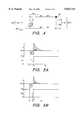
- FIGS. 3A and 3Bare timing diagrams that illustrate the voltage and current, respectively, associated with the use of the electrodes and stimulus-forming circuitry of FIG. 2;
- FIG. 4shows alternative stimulation circuitry that may be used in accordance with the invention when only biphasic stimulation pulses are desired
- FIGS. 5A and 5Bshow current and voltage waveforms associated with the operation of the circuit of FIG. 4;
- FIG. 6Ashows a radial cross sectional-view of an electrode array made in accordance with the invention, with the view being made near the base of the array;
- FIG. 6Bshows a longitudinal cross-sectional view of the electrode array of FIG. 4A, with the view being taken near the apex of the array.
- the general design of a cochlear prosthesis made in accordance with the present inventioncomprises of a multiplicity of electrode contacts made from sintered, anodized tantalum, connected via tantalum wire leads to tantalum feedthroughs into the hermetically sealed package containing the stimulus pulse-forming electronic circuitry.
- One or more counterelectrode contactsconsist of activated iridium, connected via platinum or other noble metal leads to noble metal feedthroughs.
- the stimulus generating circuitWhen powered-up, the stimulus generating circuit produces a steady polarizing potential of approximately half its maximum output voltage range, which potential is applied as a positive (anodizing) voltage to each tantalum electrode and associated lead and feedthrough, with respect to the activated iridium electrode(s), which act as the reference point for the circuit.
- This powering-up processmust be conducted slowly enough so that the currents required for the build-up of charge on the Ta electrodes do not produce undesirable stimulation or electrochemical effects; similarly, the powering-down process of discharging the Ta electrodes must be well-controlled.
- Stimulus pulses or other desired biphasic waveformsare produced by driving each tantalum electrode more or less positive than this nominal steady polarizing potential.
- the available capacitance of the sintered, anodized Ta electrodeneeds to produce a reactance to the applied current that is small compared to the rest of the impedance of the load, which consists largely of the resistance of the surrounding saline-filled tissues. Based on experience, a capacitance of about 0.1-1.0 ⁇ F should be readily attainable, which would produce a reactance of less than 1 k ⁇ compared to the tissue resistance of about 10 k ⁇ .
- the steady anodizing potential applied to the tantalum componentstends to reinforce the previously applied anodization layer, limiting to a nominal value the amount of DC that can be applied even in the event of a failure of the circuitry or a defect in the anodization layer.
- the cathodic potential applied to the iridium electrodeis absorbed by valence shifts within the activated iridium layer, as described by Loeb, et al. (1991).
- the implanted portions of the cochlear prosthesiscomprise an hermetically sealed enclosure 20 containing stimulus pulse-generating circuitry 100.
- a flexible cable 40contains electrical leads 45 that connect the circuitry 100, via feedthroughs 25, to an intracochlear electrode array 60, all disposed in saline fluids 5 of the body tissues in which these portions are surgically implanted.
- the intracochlear electrode array 60contains a multiplicity of sintered, anodized tantalum electrode contacts 65, each connected via an anodized tantalum lead 45 to an anodized tantalum feedthrough 25 that passes through and is hermetically sealed to the enclosure 20.
- One or more iridium counterelectrodes 75may be disposed within the electrode array 60 as shown in FIG.
- one or more iridium counterelectrodes 75may be located outside of the electrode array 60. Each such iridium counterelectrode 75 is connected via a noble metal conductor 55 to a noble metal feedthrough 35 of the enclosure 20. If it is desired to have the counterelectrode 75 located in a particular manner within the cochlear array as shown in FIG. 1A, or if more than one counterelectrode 75 is employed as shown in FIG. B, then the corresponding conductor(s) 55 and feedthroughs 35 should be insulated with a conventional dielectric coating 10 such as silicone elastomer or Teflon.
- a conventional dielectric coating 10such as silicone elastomer or Teflon.
- the anodized tantalum components 25, 45 and 65require no additional insulation beyond the electrochemically grown layer of tantalum pentoxide 15 (FIG. 1E) that is formed on their surfaces during manufacture or during use.
- the application of dielectric coatings, encapsulates or moldings 10may be desirable to limit the passage of alternating current from stimulation pulses between the tantalum conductors and into any surrounding saline fluids as a result of stray capacitance through the tantalum pentoxide 15.
- some such coatings, encapsulates or moldings 10will be employed to provide mechanical strain relief for the connection of wire leads to feedthroughs and to give the desired physical shape and handling properties to the electrode array 60 and flexible cable 40.
- the electrical circuitry 100applies a steady anodic polarization +Vp during periods 110 to each tantalum feedthrough 25 and its connected tantalum wire 45 and tantalum electrode contact 65, with respect to the reference point (e.g., ground reference) 120 (FIG. 2) of the circuit which is connected to the noble metal feedthrough(s) 35 and thence to any iridium counterelectrode(s) 75.
- This steady anodic polarization during the period 110is approximately half of the available power supply voltage (sum of +Vp plus +Vs) 105 that is available in the electrical circuitry 100.
- the electrical circuitry 100produces a sequence of potential changes during time 112 (FIG. 3A) in the potential applied to the particular electrode contacts through which the stimulating current is desired to flow.
- the electrode contacts 65must always be stimulated as pairings in which one or more contacts are connected so as to form one half of the pair, all of which contacts must be anodized tantalum electrode contacts 65, and one or more contacts are connected so as to form the other half of the pair, all of which contacts must be activated iridium contacts 75.
- the sequence of potential variations or changes about the polarization voltage +Vp(during time period 112) is terminated, with a return to the steady anodic polarization +Vp during period 110.
- the anodized tantalum surfaces comprising one half of the pairingact like capacitors with very low DC leakage, only charge-balanced alternating current can pass through the saline fluids 5 regardless of the potentials applied to these electrodes. If the sequence of voltage variations or changes does not itself result in no net charge flow in either direction, as shown, e.g., at time 112' (FIG. 3A), then the return to the steady anodic polarization +Vp during time 110' results in discharge of the charge stored temporarily in this capacitance, resulting in a current waveform such as shown at time 115' in FIG. 3B.
- All activated iridium contacts 75are connected to the reference point 120 of the electronic circuitry 100, which operates with only one polarity of voltages +Vs and +Vp (105) in its power supply. Thus, the electronic stimulus-forming circuitry 100 is not capable of causing net direct current to flow through the activated iridium contacts 75.
- the stimulus-forming circuitryderives a source of operating potential Vs, which it uses as a source of power within the stimulus-forming electronic circuitry.
- Vsoperating potential
- the voltage that is applied between the tantalum feedthrough(s) 25 and the noble metal feedthrough 35 by the stimulus-forming circuitry 100is varied by an amount ⁇ .increment., where the voltage amount .increment. is that amount required to cause the desired stimulating current to flow through electrode 65, but keeping such applied voltage within the range of zero to the sum of +Vp and +Vs. That is, as seen best in FIGS. 3A and 3B, the voltage appearing across the tantalum feedthrough(s) 25 and the noble metal feedthrough 35 comprises a voltage +Vp-.increment. for a period of time from t1 to t2, followed by a voltage +Vp+.increment.
- time period t1-t2be the same as the time period t2-t3 so that the resulting biphasic current pulse is balanced.
- balancingmay still be achieved even if the time periods t1-t2 and t2-t3 are not equal simply by adjusting the amplitudes of the respective negative or positive halves of the biphasic pulse.
- the first half of the biphasic pulsebe negative, as shown in FIG. 3B, such is not mandated by the present invention. It is possible to have the biphasic pulse be positive for the first half, followed by the negative pulse. What is important for purposes of the present invention is that the voltage appearing across the tantalum feedthrough(s) 25 and the noble metal feedthrough 35 be varied or changed so that it comprises a voltage +Vp ⁇ .increment. for a period of time from t1 to t2, followed by a voltage +Vp ⁇ .increment.
- cochlear electrode array and associated stimulation circuitrythat are the subject of the present invention can also be used to generate more complex stimulus waveforms having multiple or even continuous phases, subject only to the limitation imposed by the capacitive coupling that prevents creating waveforms with a net direct current flow in either direction.
- the cochlear electrode array that is a part of the present inventioncan be used advantageously with alternative stimulation circuitry 101 shown in FIG. 4.
- the alternative stimulation circuitry 101when used in conjunction with an electrode array of the type herein described, produces only biphasic pulses of the form shown in FIGS. 5A and 5B, in which the first phase 117 of the pulse applied by tantalum electrode 65 is cathodal (i.e., positively charged current flows toward the active tantalum electrode 65 from the reference iridium electrode 75).
- This polarity of biphasic pulsingis known to be more effective for stimulating excitable tissues that are physically close to the electrode contact whose first phase is cathodal.
- the shapes of the successive cathodal phase 117 and anodal phase 118are not necessarily symmetrical but that the total charge delivered (which is the area under the curve in the current vs. time traces i e in FIGS. 5A and 5B) is equal and opposite in the two successive phases 117 and 118.
- Circuit 101operates in conjunction with a single power supply 105 which is normally connected via switch 107 to tantalum electrode 65 so as to polarize potential Ee to the maximal positive voltage +Vs. Electrodes 65 and 75 and the intervening body fluids have an approximately equivalent circuit 70 composed of the series combination of electrolytic capacitance 67 and resistance 68.
- switch 107is connected for the duration of the first, cathodal phase 117 of the stimulation pulse to a stimulus control circuit 102.
- switch 107reconnects electrode 65 to power supply 105, causing anodal current 118 to flow as capacitance 67 is repolarized to the value +Vs. Because of capacitance 67, the charge transferred during cathodal phase 117 must be equal and opposite to that transferred during anodal phase 118.
- stimulus control circuit 102may perform the function of permitting a regulated current to flow.
- the strength of the stimulation pulseis determined by controlling the amplitude and duration of the current. This results in the waveforms of electrode current i e and potential Ee shown in FIG. 5A.
- cathodal phase 117which lasts from t1 to t2, circuit 102 pulls potential Ee progressively lower in order to maintain constant current flow as capacitance 67 is discharged.
- anodal phase 118from t2 to t3, the current i e varies exponentially according to the time constant determined by capacitance 67, resistance 68 and any internal resistance of other conductors and power supplies in the circuit.
- the strength of a stimulation pulsemay be determined by controlling the total charge of its cathodal phase 117, without explicitly controlling either the current or the duration.
- FIG. 5Bshows one possible set of waveforms of the electrode current i e and potential Ee that can be generated in this manner.
- circuit 102effectively short-circuits tantalum electrode 65 to reference electrode 75, causing Ee to fall to zero.
- Current i eflows according to the time constant determined by capacitance 67, resistance 68 and any internal resistances.
- circuit 102After the required cathodal charge has flowed, from time t2 to t3, circuit 102 goes into an open state in which no current flows, during which Ee represents the residual charge remaining on capacitance 67.
- Anodal phase 118is produced by reconnecting electrode 65 to power supply 105.
- This method of controlling stimulus intensity by metering charge instead of currenthas the advantage of eliminating the dissipation of power that normally occurs in current-regulating circuits. It generates the shortest possible duration of cathodal pulse that can be produced given the available power supply voltage +Vs and impedance of equivalent circuit 70. It permits a delay interval between the cathodal and anodal pulses, which is known to improve the efficiency of the neural response to electrical stimulation with brief, biphasic pulses.
- FIGS. 6A and 6Bdetails are shown of a more complete and explicit design for a cochlear electrode array 200 that incorporates several features of the present invention plus additional features of inventions disclosed in pending patent applications.
- FIG. 6Ashows a transverse cross sectional-view of the electrode array 200 with the sectional view being made near the base of the array.
- FIG. 6Bshows a longitudinal cross-sectional view of the electrode array 200, with the sectional view being taken near the apex of the array.
- the array 200is preferably made from a silicone molding 202 with a complex cross-section and a performed spiral shape that is designed to optimally position a set of 24 sintered Ta contacts 206 at regular intervals of about 0.8 mm over most of the 24 mm length of the array.
- Each contactfaces the medial wall of the scala tympani and is surrounded by a very thin, deformable ring 208 of molded silicone that acts like a gasket to force its stimulating current into the bone overlying the spiral ganglion cells.
- These contacts and gasketsare forced against the medial wall by the combined pull of the springy spiral shape and the push of a longitudinally disposed fin 204 directed toward the lateral wall.
- Two elongated common electrodes 210, 212are shown above and below the horizontal meridian and facing laterally. One or the other of these electrodes 210 or 212 would be electronically switched to the reference point 120 of the circuitry to act as the return electrode in a bipolar edge-effect array as described in the '758 patent application referenced above. Note that the edge-to-edge distance of the Ir to adjacent Ta electrodes is, in fact, short enough to produce the desired bipolar focusing based on edge-effects, even though the contacts actually face in opposite directions.
- the upper Ir common electrode 210would be most useful when stimulating spiral ganglion cells with a high rate of apical dendrite survival because it would produce current flow through the habenula perforata in which such dendrites lie.
- the lower Ir common electrode 212would be most useful when stimulating spiral ganglion cell bodies directly, as these lie mostly below the horizontal meridian, with axonal processes projecting downward into the modiolar bone. Note that because of the resting polarization of the Ta at a potential of +Vp, (approximately half the operating voltage range) it is possible to apply either anodal-first or cathodal-first biphasic pulses in either bipolar configuration.
- the 24 Ta leads connecting to each of the 24 Ta electrodesare organized into two 12-conductor ribbon cables 215, each consisting of 12 0.001" Ta conductors held on 0.003" centers by a Teflon extrusion 216. Individual leads from these ribbon cables are stripped of the Teflon carrier 216 by a highly focused laser, which melts the end of the Ta wire into a small ball and welds it to the sintered Ta electrode contact 206. It is important to make such connections without contacting the Ta parts with another metal (such as might be employed in resistance welding electrodes), because metallic impurities in the Ta may interfere with the formation of a leak-free anodization layer.
- the Ta leadswould be similarly laser welded to the Ta feedthroughs 25 on the hermetic package and the subassembly of Ta contacts.
- the ribbon cables 215 and feedthroughs 25would then be anodized to about 4 times the maximum anticipated working voltage (the sum of +Vp plus +Vs) to provide a leak-free anodization layer.
- This subassemblywould then be placed in the mold along with the ribbon-shaped Ir common electrodes 210, 212.
- a single injection processwould simultaneously form the silicone material comprising the electrode carrier 216, the flexible lead cable 45 and the strain-relief 40 over the feedthroughs 25.
- any voids or defects in the Teflon of the ribbon cable or the silicone materialwould be inconsequential sources of shunts because of the prior or eventual anodization of all potentially exposed Ta surfaces.
- Any shunts relative to the Ir electrodes 210, 212, their noble metal leads 55 and feedthroughs 35would also be inconsequential because of the principle of the edge-effect electrode, in which only the region of the common electrode surface that is immediately adjacent to the active electrode actually carries any significant amount of current.
Landscapes
- Health & Medical Sciences (AREA)
- Otolaryngology (AREA)
- Animal Behavior & Ethology (AREA)
- Engineering & Computer Science (AREA)
- Biomedical Technology (AREA)
- Nuclear Medicine, Radiotherapy & Molecular Imaging (AREA)
- Radiology & Medical Imaging (AREA)
- Life Sciences & Earth Sciences (AREA)
- General Health & Medical Sciences (AREA)
- Public Health (AREA)
- Veterinary Medicine (AREA)
- Heart & Thoracic Surgery (AREA)
- Cardiology (AREA)
- Prostheses (AREA)
Abstract
Description
Claims (7)
Priority Applications (2)
| Application Number | Priority Date | Filing Date | Title |
|---|---|---|---|
| US08/784,209US5833714A (en) | 1996-01-18 | 1997-01-15 | Cochlear electrode array employing tantalum metal |
| US08/951,893US5957958A (en) | 1997-01-15 | 1997-10-16 | Implantable electrode arrays |
Applications Claiming Priority (2)
| Application Number | Priority Date | Filing Date | Title |
|---|---|---|---|
| US1015696P | 1996-01-18 | 1996-01-18 | |
| US08/784,209US5833714A (en) | 1996-01-18 | 1997-01-15 | Cochlear electrode array employing tantalum metal |
Related Child Applications (1)
| Application Number | Title | Priority Date | Filing Date |
|---|---|---|---|
| US08/951,893Continuation-In-PartUS5957958A (en) | 1997-01-15 | 1997-10-16 | Implantable electrode arrays |
Publications (1)
| Publication Number | Publication Date |
|---|---|
| US5833714Atrue US5833714A (en) | 1998-11-10 |
Family
ID=26680844
Family Applications (1)
| Application Number | Title | Priority Date | Filing Date |
|---|---|---|---|
| US08/784,209Expired - Fee RelatedUS5833714A (en) | 1996-01-18 | 1997-01-15 | Cochlear electrode array employing tantalum metal |
Country Status (1)
| Country | Link |
|---|---|
| US (1) | US5833714A (en) |
Cited By (85)
| Publication number | Priority date | Publication date | Assignee | Title |
|---|---|---|---|---|
| US5957958A (en)* | 1997-01-15 | 1999-09-28 | Advanced Bionics Corporation | Implantable electrode arrays |
| WO2000047272A1 (en) | 1999-02-09 | 2000-08-17 | Advanced Bionics Corporation | Cochlear electrode array with electrode contacts on medial side |
| US6253099B1 (en)* | 1999-08-19 | 2001-06-26 | Lifecor, Inc. | Cardiac monitoring electrode apparatus and method |
| US20010031909A1 (en)* | 2000-03-31 | 2001-10-18 | Faltys Michael A. | High contact count, sub-miniature, fully implantable cochlear prosthesis |
| US6309410B1 (en)* | 1998-08-26 | 2001-10-30 | Advanced Bionics Corporation | Cochlear electrode with drug delivery channel and method of making same |
| US6314324B1 (en) | 1999-05-05 | 2001-11-06 | Respironics, Inc. | Vestibular stimulation system and method |
| US6321125B1 (en) | 1998-08-26 | 2001-11-20 | Advanced Bionics Corporation | Cochlear electrode system including distally attached flexible positioner |
| US6397110B1 (en) | 1998-08-26 | 2002-05-28 | Advanced Bionics Corporation | Cochlear electrode system including detachable flexible positioner |
| US20020168817A1 (en)* | 2001-05-03 | 2002-11-14 | Soon-Yong Kweon | Fabricating ferroelectric memory device |
| US6487453B1 (en) | 1999-08-09 | 2002-11-26 | Advanced Bionics Corporation | Electrode system for ossified cochlea |
| US6537201B1 (en) | 2001-09-28 | 2003-03-25 | Otologics Llc | Implantable hearing aid with improved sealing |
| US6586675B1 (en)* | 1999-12-03 | 2003-07-01 | Morgan Advanced Ceramics, Inc. | Feedthrough devices |
| US20040015221A1 (en)* | 2000-10-10 | 2004-01-22 | Kuzma Janusz A. | Band type multicontact electrode and method of making the same |
| WO2004030159A1 (en)* | 2002-09-30 | 2004-04-08 | Cochlear Limited | Feedthrough for electrical connectors |
| US6748275B2 (en) | 1999-05-05 | 2004-06-08 | Respironics, Inc. | Vestibular stimulation system and method |
| US6757970B1 (en) | 2000-11-07 | 2004-07-06 | Advanced Bionics Corporation | Method of making multi-contact electrode array |
| US20050240253A1 (en)* | 2003-11-26 | 2005-10-27 | Wicab, Inc. | Systems and methods for altering vestibular biology |
| US20060004432A1 (en)* | 2004-06-23 | 2006-01-05 | Cochlear Limited | Methods for maintaining low impedance of electrodes |
| US20060235490A1 (en)* | 2000-08-21 | 2006-10-19 | Cochlear Limited | Determining stimulation signals for neural stimulation |
| US20060241718A1 (en)* | 2003-11-26 | 2006-10-26 | Wicab, Inc. | Systems and methods for altering brain and body functions and for treating conditions and diseases of the same |
| WO2005108914A3 (en)* | 2004-05-06 | 2006-12-14 | Zetetic Inst | Apparatus and methods for measurement of critical dimensions of features and detection of defects in uv, vuv, and euv lithography masks |
| US20070083078A1 (en)* | 2005-10-06 | 2007-04-12 | Easter James R | Implantable transducer with transverse force application |
| US20070127745A1 (en)* | 2005-12-07 | 2007-06-07 | Cochlear Limited | Prevention of static bonding between medical device components |
| US20070128940A1 (en)* | 2003-12-08 | 2007-06-07 | Cochlear Limited | Cochlear implant assembly |
| US20070244410A1 (en)* | 2006-04-18 | 2007-10-18 | Advanced Bionics Corporation | Removing Artifact in Evoked Compound Action Potential Recordings in Neural Stimulators |
| US20090062896A1 (en)* | 2007-08-29 | 2009-03-05 | Overstreet Edward H | Minimizing Trauma During and After Insertion of a Cochlear Lead |
| WO2009048580A1 (en)* | 2007-10-09 | 2009-04-16 | Imthera Medical, Inc. | Apparatus, system, and method for selective stimulation |
| US20090118795A1 (en)* | 2001-06-29 | 2009-05-07 | Cochlear Limited | Multi-electrode cochlear implant system with distributed electronics |
| US20090157142A1 (en)* | 2007-11-26 | 2009-06-18 | Microtransponder Inc. | Implanted Driver with Charge Balancing |
| US20090157145A1 (en)* | 2007-11-26 | 2009-06-18 | Lawrence Cauller | Transfer Coil Architecture |
| US20090177247A1 (en)* | 2000-08-21 | 2009-07-09 | Cochlear Limited | Determining stimulation signals for neural stimulation |
| US20090198293A1 (en)* | 2003-12-19 | 2009-08-06 | Lawrence Cauller | Microtransponder Array for Implant |
| US20090292237A1 (en)* | 2007-08-29 | 2009-11-26 | Advanced Bionics, Llc | Modular Drug Delivery System for Minimizing Trauma During and After Insertion of a Cochlear Lead |
| US20090306741A1 (en)* | 2006-10-26 | 2009-12-10 | Wicab, Inc. | Systems and methods for altering brain and body functions and for treating conditions and diseases of the same |
| US20090312817A1 (en)* | 2003-11-26 | 2009-12-17 | Wicab, Inc. | Systems and methods for altering brain and body functions and for treating conditions and diseases of the same |
| US20100003656A1 (en)* | 2008-07-02 | 2010-01-07 | The Board Of Regents, The University Of Texas System | Systems, methods and devices for paired plasticity |
| US20100022908A1 (en)* | 2003-12-19 | 2010-01-28 | Board Of Regents, The University Of Texas System | System and Method for Interfacing Cellular Matter with a Machine |
| US20100069994A1 (en)* | 2007-06-25 | 2010-03-18 | Microtransponder, Inc. | Methods of inducing paresthesia using wireless neurostimulation |
| US20100305675A1 (en)* | 2009-05-29 | 2010-12-02 | Laske Timothy G | Leads for selective sensing and virtual electrodes |
| US20100326723A1 (en)* | 2007-07-17 | 2010-12-30 | Cochlear Limited | Electrically insulative structure having holes for feedthroughs |
| US20110077698A1 (en)* | 2009-09-28 | 2011-03-31 | Kostas Tsampazis | Method and circuitry for measurement of stimulation current |
| US20110152991A1 (en)* | 2008-06-20 | 2011-06-23 | Fysh Dadd | Strain relief in an implantable electrode assembly |
| US20110160798A1 (en)* | 2009-11-23 | 2011-06-30 | Case Western Reserve University | Separated-interface nerve electrode |
| US8050770B2 (en) | 2000-08-21 | 2011-11-01 | Cochlear Limited | Power efficient electrical stimulation |
| US20120004715A1 (en)* | 2010-06-30 | 2012-01-05 | Med-El Elektromedizinische Geraete Gmbh | Ear Implant Electrode and Method of Manufacture |
| US8457757B2 (en) | 2007-11-26 | 2013-06-04 | Micro Transponder, Inc. | Implantable transponder systems and methods |
| US8515540B2 (en) | 2011-02-24 | 2013-08-20 | Cochlear Limited | Feedthrough having a non-linear conductor |
| US8755910B2 (en) | 2009-06-15 | 2014-06-17 | Cochlear Limited | Reference electrodes for inner ear stimulation devices |
| US8774937B2 (en) | 2009-12-01 | 2014-07-08 | Ecole Polytechnique Federale De Lausanne | Microfabricated surface neurostimulation device and methods of making and using the same |
| US8788042B2 (en) | 2008-07-30 | 2014-07-22 | Ecole Polytechnique Federale De Lausanne (Epfl) | Apparatus and method for optimized stimulation of a neurological target |
| US8788064B2 (en) | 2008-11-12 | 2014-07-22 | Ecole Polytechnique Federale De Lausanne | Microfabricated neurostimulation device |
| US8965500B2 (en) | 2007-06-06 | 2015-02-24 | Zoll Medical Corporation | Wearable defibrillator with audio input/output |
| US8996111B2 (en) | 2012-04-27 | 2015-03-31 | Medtronic, Inc. | Lead recognition for an implantable medical system |
| US9079037B2 (en) | 2012-04-27 | 2015-07-14 | Medtronic, Inc. | Fault tolerant implantable medical system |
| US9204813B2 (en) | 2011-03-25 | 2015-12-08 | Zoll Medical Corporation | Method of detecting signal clipping in a wearable ambulatory medical device |
| US9370311B2 (en) | 2012-08-17 | 2016-06-21 | Medtronic Ablation Frontiers Llc | Electrophysiology catheter design |
| US9403011B2 (en) | 2014-08-27 | 2016-08-02 | Aleva Neurotherapeutics | Leadless neurostimulator |
| US9408548B2 (en) | 2011-03-25 | 2016-08-09 | Zoll Medical Corporation | Selection of optimal channel for rate determination |
| US9474894B2 (en) | 2014-08-27 | 2016-10-25 | Aleva Neurotherapeutics | Deep brain stimulation lead |
| US9549708B2 (en) | 2010-04-01 | 2017-01-24 | Ecole Polytechnique Federale De Lausanne | Device for interacting with neurological tissue and methods of making and using the same |
| US9855414B2 (en) | 2014-04-25 | 2018-01-02 | Medtronic, Inc. | Implantable extravascular electrical stimulation lead having improved sensing and pacing capability |
| US9925376B2 (en) | 2014-08-27 | 2018-03-27 | Aleva Neurotherapeutics | Treatment of autoimmune diseases with deep brain stimulation |
| US10272240B2 (en) | 2017-04-03 | 2019-04-30 | Presidio Medical, Inc. | Systems and methods for direct current nerve conduction block |
| US10589087B2 (en) | 2003-11-26 | 2020-03-17 | Wicab, Inc. | Systems and methods for altering brain and body functions and for treating conditions and diseases of the same |
| US10675478B2 (en) | 2014-12-09 | 2020-06-09 | Medtronic, Inc. | Extravascular implantable electrical lead having undulating configuration |
| US10765858B2 (en) | 2014-11-05 | 2020-09-08 | Medtronic, Inc. | Extravascular lead designs for optimized pacing and sensing having segmented, partially electrically insulated defibrillation coils |
| US10864373B2 (en) | 2015-12-15 | 2020-12-15 | Case Western Reserve University | Systems for treatment of a neurological disorder using electrical nerve conduction block |
| US10874865B2 (en) | 2017-11-06 | 2020-12-29 | Avx Corporation | EMI feedthrough filter terminal assembly containing a resin coating over a hermetically sealing material |
| US10966620B2 (en) | 2014-05-16 | 2021-04-06 | Aleva Neurotherapeutics Sa | Device for interacting with neurological tissue and methods of making and using the same |
| US11026627B2 (en) | 2013-03-15 | 2021-06-08 | Cadwell Laboratories, Inc. | Surgical instruments for determining a location of a nerve during a procedure |
| US11033734B2 (en) | 2012-06-15 | 2021-06-15 | Case Western Reserve University | Treatment of pain using electrical nerve conduction block |
| US11058871B2 (en) | 2003-12-08 | 2021-07-13 | Cochlear Limited | Manufacturing an electrode array for a stimulating medical device |
| US11177610B2 (en) | 2017-01-23 | 2021-11-16 | Cadwell Laboratories, ino. | Neuromonitoring connection system |
| US11253182B2 (en) | 2018-05-04 | 2022-02-22 | Cadwell Laboratories, Inc. | Apparatus and method for polyphasic multi-output constant-current and constant-voltage neurophysiological stimulation |
| US11266830B2 (en) | 2018-03-02 | 2022-03-08 | Aleva Neurotherapeutics | Neurostimulation device |
| WO2022069713A1 (en)* | 2020-10-02 | 2022-04-07 | Fraunhofer-Gesellschaft zur Förderung der angewandten Forschung e.V. | Active implantable medical product and method for producing same |
| US11311718B2 (en) | 2014-05-16 | 2022-04-26 | Aleva Neurotherapeutics Sa | Device for interacting with neurological tissue and methods of making and using the same |
| US11443649B2 (en) | 2018-06-29 | 2022-09-13 | Cadwell Laboratories, Inc. | Neurophysiological monitoring training simulator |
| US11504527B2 (en) | 2012-06-15 | 2022-11-22 | Case Western Reserve University | Therapy delivery devices and methods for non-damaging neural tissue conduction block |
| US11730964B2 (en) | 2019-11-24 | 2023-08-22 | Presidio Medical, Inc. | Pulse generation and stimulation engine systems |
| US11752329B2 (en) | 2018-07-01 | 2023-09-12 | Presidio Medical, Inc. | Systems and methods for nerve conduction block |
| US11813459B2 (en) | 2018-02-20 | 2023-11-14 | Presidio Medical, Inc. | Methods and systems for nerve conduction block |
| US11896835B2 (en) | 2017-10-25 | 2024-02-13 | Cochlear Limited | Electrical shielding in implantable medical devices |
| US11992339B2 (en) | 2018-05-04 | 2024-05-28 | Cadwell Laboratories, Inc. | Systems and methods for dynamic neurophysiological stimulation |
| US12268865B2 (en) | 2019-11-24 | 2025-04-08 | Presidio Medical, Inc. | Current bias as a control mechanism for electrode operation |
Citations (14)
| Publication number | Priority date | Publication date | Assignee | Title |
|---|---|---|---|---|
| US3646940A (en)* | 1969-07-15 | 1972-03-07 | Univ Minnesota | Implantable electronic stimulator electrode and method |
| US4006748A (en)* | 1976-01-29 | 1977-02-08 | Pacestter Systems, Inc. | Implantable unipolar pacemaker with improved outer electrode plate |
| US4333072A (en)* | 1979-08-06 | 1982-06-01 | International Identification Incorporated | Identification device |
| US4408608A (en)* | 1981-04-09 | 1983-10-11 | Telectronics Pty. Ltd. | Implantable tissue-stimulating prosthesis |
| US4440178A (en)* | 1980-12-23 | 1984-04-03 | Kontron Ag | Implantable electrode |
| US4494545A (en)* | 1980-05-27 | 1985-01-22 | Cordis Corporation | Implant telemetry system |
| US4524774A (en)* | 1981-07-30 | 1985-06-25 | Deutsche Nemectron Gmbh | Apparatus and method for the stimulation of a human muscle |
| US4532930A (en)* | 1983-04-11 | 1985-08-06 | Commonwealth Of Australia, Dept. Of Science & Technology | Cochlear implant system for an auditory prosthesis |
| US4679560A (en)* | 1985-04-02 | 1987-07-14 | Board Of Trustees Of The Leland Stanford Junior University | Wide band inductive transdermal power and data link |
| US4763656A (en)* | 1985-06-13 | 1988-08-16 | Beatrice T. Kester | Transcutaneous electrical nerve stimulation device and method |
| US5193540A (en)* | 1991-12-18 | 1993-03-16 | Alfred E. Mann Foundation For Scientific Research | Structure and method of manufacture of an implantable microstimulator |
| US5193539A (en)* | 1991-12-18 | 1993-03-16 | Alfred E. Mann Foundation For Scientific Research | Implantable microstimulator |
| US5312439A (en)* | 1991-12-12 | 1994-05-17 | Loeb Gerald E | Implantable device having an electrolytic storage electrode |
| US5466247A (en)* | 1992-05-18 | 1995-11-14 | Case Western Reserve University | Subcutaneous electrode for stimulating skeletal musculature |
- 1997
- 1997-01-15USUS08/784,209patent/US5833714A/ennot_activeExpired - Fee Related
Patent Citations (16)
| Publication number | Priority date | Publication date | Assignee | Title |
|---|---|---|---|---|
| US3646940A (en)* | 1969-07-15 | 1972-03-07 | Univ Minnesota | Implantable electronic stimulator electrode and method |
| US4006748A (en)* | 1976-01-29 | 1977-02-08 | Pacestter Systems, Inc. | Implantable unipolar pacemaker with improved outer electrode plate |
| US4333072A (en)* | 1979-08-06 | 1982-06-01 | International Identification Incorporated | Identification device |
| US4494545A (en)* | 1980-05-27 | 1985-01-22 | Cordis Corporation | Implant telemetry system |
| US4440178A (en)* | 1980-12-23 | 1984-04-03 | Kontron Ag | Implantable electrode |
| US4408608A (en)* | 1981-04-09 | 1983-10-11 | Telectronics Pty. Ltd. | Implantable tissue-stimulating prosthesis |
| US4524774A (en)* | 1981-07-30 | 1985-06-25 | Deutsche Nemectron Gmbh | Apparatus and method for the stimulation of a human muscle |
| US4532930A (en)* | 1983-04-11 | 1985-08-06 | Commonwealth Of Australia, Dept. Of Science & Technology | Cochlear implant system for an auditory prosthesis |
| US4679560A (en)* | 1985-04-02 | 1987-07-14 | Board Of Trustees Of The Leland Stanford Junior University | Wide band inductive transdermal power and data link |
| US4763656A (en)* | 1985-06-13 | 1988-08-16 | Beatrice T. Kester | Transcutaneous electrical nerve stimulation device and method |
| US5312439A (en)* | 1991-12-12 | 1994-05-17 | Loeb Gerald E | Implantable device having an electrolytic storage electrode |
| US5193540A (en)* | 1991-12-18 | 1993-03-16 | Alfred E. Mann Foundation For Scientific Research | Structure and method of manufacture of an implantable microstimulator |
| US5193539A (en)* | 1991-12-18 | 1993-03-16 | Alfred E. Mann Foundation For Scientific Research | Implantable microstimulator |
| US5324316A (en)* | 1991-12-18 | 1994-06-28 | Alfred E. Mann Foundation For Scientific Research | Implantable microstimulator |
| US5405367A (en)* | 1991-12-18 | 1995-04-11 | Alfred E. Mann Foundation For Scientific Research | Structure and method of manufacture of an implantable microstimulator |
| US5466247A (en)* | 1992-05-18 | 1995-11-14 | Case Western Reserve University | Subcutaneous electrode for stimulating skeletal musculature |
Non-Patent Citations (22)
| Title |
|---|
| "Capacitor Electrode Stimulates Nerve or Muscle without Oxidation-Reduction Reactions", Science, vol. 181, pp. 74-76. |
| "CRC Critical Review in Bioengineering", pp. 77-79 (Sep. 1981). |
| Capacitor Electrode Stimulates Nerve or Muscle without Oxidation Reduction Reactions , Science , vol. 181, pp. 74 76.* |
| CRC Critical Review in Bioengineering , pp. 77 79 (Sep. 1981).* |
| Guyton, et al., "Theory and Design of Capacitor Electrodes for Chronic Stimulation", Medical and Biological Engineering, pp. 613-619 (Sep. 1974). |
| Guyton, et al., Theory and Design of Capacitor Electrodes for Chronic Stimulation , Medical and Biological Engineering , pp. 613 619 (Sep. 1974).* |
| Heetderks, "RF Powering of Millimeter-and Submillimeter-Sized Neural Prosthetic Implants", IEEE Transactions on Biomedical Engineering, vol. 35:5, pp. 323-326 (May 1988). |
| Heetderks, RF Powering of Millimeter and Submillimeter Sized Neural Prosthetic Implants , IEEE Transactions on Biomedical Engineering , vol. 35:5, pp. 323 326 (May 1988).* |
| Kaximierczuk, et al., "Exact Analysis of Class E Tuned Power Amplifier at any Q and Switch Duty Cycle", IEEE Transactions on Circuits and Systems, vol. CAS-34:2, pp. 149-159 (Feb. 1987). |
| Kaximierczuk, et al., Exact Analysis of Class E Tuned Power Amplifier at any Q and Switch Duty Cycle , IEEE Transactions on Circuits and Systems , vol. CAS 34:2, pp. 149 159 (Feb. 1987).* |
| Lagow, et al., "Anodic Insulated Tantalum Oxide Electrocardiograph Electrodes", IEEE Transactions on Bio-Medical Engineering, pp. 162-164 (Mar. 1971). |
| Lagow, et al., Anodic Insulated Tantalum Oxide Electrocardiograph Electrodes , IEEE Transactions on Bio Medical Engineering , pp. 162 164 (Mar. 1971).* |
| Loeb, et al., "Injectable Microstimulator for Functional Electrical Stimulation", Medical and Biological Engineering and Computer, 29:NS 13-19 (1991). |
| Loeb, et al., Injectable Microstimulator for Functional Electrical Stimulation , Medical and Biological Engineering and Computer , 29:NS 13 19 (1991).* |
| Product Description, features and diagram of "Implantable Transponder TX1400" from Identification Devices, Inc. |
| Product Description, features and diagram of Implantable Transponder TX1400 from Identification Devices, Inc.* |
| Robblee, et al., "Activated Ir: An Electrode Suitable for Reversible Charge Injection in Saline Solution", J. Electrochem. Soc.: Accelerated Brief Communication, vol. 130:3, pp. 731-733, (Mar. 1983). |
| Robblee, et al., Activated Ir: An Electrode Suitable for Reversible Charge Injection in Saline Solution , J. Electrochem. Soc.: Accelerated Brief Communication, vol. 130:3, pp. 731 733, (Mar. 1983).* |
| Rose, et al., "Assessment of Capacitor Electrodes for Intracortical Neural Stimulation", Journal of Neuroscience Methods, vol. 12, pp. 181-193 (1985). |
| Rose, et al., Assessment of Capacitor Electrodes for Intracortical Neural Stimulation , Journal of Neuroscience Methods , vol. 12, pp. 181 193 (1985).* |
| White, "The Stanford Artificial Ear Project", The Stanford Engineer, pp. 3-10 (Spring/Summer 1980). |
| White, The Stanford Artificial Ear Project , The Stanford Engineer , pp. 3 10 (Spring/Summer 1980).* |
Cited By (192)
| Publication number | Priority date | Publication date | Assignee | Title |
|---|---|---|---|---|
| US5957958A (en)* | 1997-01-15 | 1999-09-28 | Advanced Bionics Corporation | Implantable electrode arrays |
| US6321125B1 (en) | 1998-08-26 | 2001-11-20 | Advanced Bionics Corporation | Cochlear electrode system including distally attached flexible positioner |
| US6309410B1 (en)* | 1998-08-26 | 2001-10-30 | Advanced Bionics Corporation | Cochlear electrode with drug delivery channel and method of making same |
| US6397110B1 (en) | 1998-08-26 | 2002-05-28 | Advanced Bionics Corporation | Cochlear electrode system including detachable flexible positioner |
| WO2000047272A1 (en) | 1999-02-09 | 2000-08-17 | Advanced Bionics Corporation | Cochlear electrode array with electrode contacts on medial side |
| EP1159027A4 (en)* | 1999-02-09 | 2008-12-17 | Advanced Bionics Corp | Universal cochlear electrode array with electrode contacts on medial side |
| US20080275293A1 (en)* | 1999-05-05 | 2008-11-06 | Ric Investments, Llc. | Vestibular Stimulation System and Method |
| US6314324B1 (en) | 1999-05-05 | 2001-11-06 | Respironics, Inc. | Vestibular stimulation system and method |
| US20040215236A1 (en)* | 1999-05-05 | 2004-10-28 | Respironics, Inc. | Vestibular stimulation system and method |
| US20080275292A1 (en)* | 1999-05-05 | 2008-11-06 | Ric Investments, Llc. | Vestibular Stimulation System and Method |
| US7469162B2 (en) | 1999-05-05 | 2008-12-23 | Ric Investments, Llc | Vestibular stimulation system and method |
| US7856274B2 (en) | 1999-05-05 | 2010-12-21 | Ric Investments, Llc | Vestibular stimulation system and method |
| US8355788B2 (en) | 1999-05-05 | 2013-01-15 | Ric Investments, Llc | Vestibular stimulation system and method |
| US6748275B2 (en) | 1999-05-05 | 2004-06-08 | Respironics, Inc. | Vestibular stimulation system and method |
| US6487453B1 (en) | 1999-08-09 | 2002-11-26 | Advanced Bionics Corporation | Electrode system for ossified cochlea |
| US6253099B1 (en)* | 1999-08-19 | 2001-06-26 | Lifecor, Inc. | Cardiac monitoring electrode apparatus and method |
| US6586675B1 (en)* | 1999-12-03 | 2003-07-01 | Morgan Advanced Ceramics, Inc. | Feedthrough devices |
| US20040082985A1 (en)* | 2000-03-31 | 2004-04-29 | Faltys Michael A. | High contact count, sub-miniature, fully implantable cochlear prosthesis |
| US6826430B2 (en)* | 2000-03-31 | 2004-11-30 | Advanced Bionics Corporation | High contact count, sub-miniature, fully implantable cochlear prosthesis |
| US7444185B1 (en) | 2000-03-31 | 2008-10-28 | Advanced Bionics, Llc | High contact count, sub-miniature, fully implantable cochlear prosthesis |
| US6980864B2 (en) | 2000-03-31 | 2005-12-27 | Advanced Bionics Corporation | High contact count, sub-miniature, full implantable cochlear prosthesis |
| US20010031909A1 (en)* | 2000-03-31 | 2001-10-18 | Faltys Michael A. | High contact count, sub-miniature, fully implantable cochlear prosthesis |
| US8050770B2 (en) | 2000-08-21 | 2011-11-01 | Cochlear Limited | Power efficient electrical stimulation |
| US20090177247A1 (en)* | 2000-08-21 | 2009-07-09 | Cochlear Limited | Determining stimulation signals for neural stimulation |
| US20060235490A1 (en)* | 2000-08-21 | 2006-10-19 | Cochlear Limited | Determining stimulation signals for neural stimulation |
| US8285382B2 (en) | 2000-08-21 | 2012-10-09 | Cochlear Limited | Determining stimulation signals for neural stimulation |
| US9008786B2 (en) | 2000-08-21 | 2015-04-14 | Cochlear Limited | Determining stimulation signals for neural stimulation |
| US20040015221A1 (en)* | 2000-10-10 | 2004-01-22 | Kuzma Janusz A. | Band type multicontact electrode and method of making the same |
| US7047081B2 (en) | 2000-10-10 | 2006-05-16 | Advanced Bionics Corporation | Band type multicontact electrode and method of making the same |
| US6757970B1 (en) | 2000-11-07 | 2004-07-06 | Advanced Bionics Corporation | Method of making multi-contact electrode array |
| US6946340B2 (en) | 2001-05-03 | 2005-09-20 | Hynix Semiconductor Inc. | Method of fabricating ferroelectric memory device with photoresist and capping layer |
| US20020168817A1 (en)* | 2001-05-03 | 2002-11-14 | Soon-Yong Kweon | Fabricating ferroelectric memory device |
| US20090118795A1 (en)* | 2001-06-29 | 2009-05-07 | Cochlear Limited | Multi-electrode cochlear implant system with distributed electronics |
| US8082040B2 (en) | 2001-06-29 | 2011-12-20 | Cochlear Limited | Multi-electrode cochlear implant system with distributed electronics |
| US6537201B1 (en) | 2001-09-28 | 2003-03-25 | Otologics Llc | Implantable hearing aid with improved sealing |
| US20080208289A1 (en)* | 2002-09-30 | 2008-08-28 | Cochlear Limited | Feedthrough for electrical connectors |
| US20060141861A1 (en)* | 2002-09-30 | 2006-06-29 | Cochlear Limited | Feedthrough for electrical connectors |
| US20080209723A1 (en)* | 2002-09-30 | 2008-09-04 | Cochlear Limited | Feedthrough for electrical connectors |
| US7396265B2 (en) | 2002-09-30 | 2008-07-08 | Cochlear Limited | Feedthrough for electrical connectors |
| US7988507B2 (en) | 2002-09-30 | 2011-08-02 | Cochlear Limited | Feedthrough for electrical connectors |
| US7996982B2 (en) | 2002-09-30 | 2011-08-16 | Cochlear Limited | Method of making feedthroughs for electrical connectors |
| WO2004030159A1 (en)* | 2002-09-30 | 2004-04-08 | Cochlear Limited | Feedthrough for electrical connectors |
| US20050240253A1 (en)* | 2003-11-26 | 2005-10-27 | Wicab, Inc. | Systems and methods for altering vestibular biology |
| US10589087B2 (en) | 2003-11-26 | 2020-03-17 | Wicab, Inc. | Systems and methods for altering brain and body functions and for treating conditions and diseases of the same |
| US20090326604A1 (en)* | 2003-11-26 | 2009-12-31 | Wicab, Inc. | Systems and methods for altering vestibular biology |
| US20090312817A1 (en)* | 2003-11-26 | 2009-12-17 | Wicab, Inc. | Systems and methods for altering brain and body functions and for treating conditions and diseases of the same |
| US20060241718A1 (en)* | 2003-11-26 | 2006-10-26 | Wicab, Inc. | Systems and methods for altering brain and body functions and for treating conditions and diseases of the same |
| US11058871B2 (en) | 2003-12-08 | 2021-07-13 | Cochlear Limited | Manufacturing an electrode array for a stimulating medical device |
| US7950134B2 (en) | 2003-12-08 | 2011-05-31 | Cochlear Limited | Implantable antenna |
| US20070128940A1 (en)* | 2003-12-08 | 2007-06-07 | Cochlear Limited | Cochlear implant assembly |
| US20110230944A1 (en)* | 2003-12-08 | 2011-09-22 | Andy Ho | Implantable antenna |
| US8819919B2 (en) | 2003-12-08 | 2014-09-02 | Cochlear Limited | Method of forming a non-linear path of an electrically conducting wire |
| US20100022908A1 (en)* | 2003-12-19 | 2010-01-28 | Board Of Regents, The University Of Texas System | System and Method for Interfacing Cellular Matter with a Machine |
| US20090198293A1 (en)* | 2003-12-19 | 2009-08-06 | Lawrence Cauller | Microtransponder Array for Implant |
| WO2005108914A3 (en)* | 2004-05-06 | 2006-12-14 | Zetetic Inst | Apparatus and methods for measurement of critical dimensions of features and detection of defects in uv, vuv, and euv lithography masks |
| US20090204177A1 (en)* | 2004-06-23 | 2009-08-13 | Cochlear Limited | Maintaining low impedance of electrodes |
| US20060004432A1 (en)* | 2004-06-23 | 2006-01-05 | Cochlear Limited | Methods for maintaining low impedance of electrodes |
| US8175722B2 (en) | 2004-06-23 | 2012-05-08 | Cochlear Limited | Maintaining low impedance of electrodes |
| US7519435B2 (en)* | 2004-06-23 | 2009-04-14 | Cochlear Limited | Methods for maintaining low impedance of electrodes |
| US20070083078A1 (en)* | 2005-10-06 | 2007-04-12 | Easter James R | Implantable transducer with transverse force application |
| US7753838B2 (en) | 2005-10-06 | 2010-07-13 | Otologics, Llc | Implantable transducer with transverse force application |
| US20070127745A1 (en)* | 2005-12-07 | 2007-06-07 | Cochlear Limited | Prevention of static bonding between medical device components |
| US7835804B2 (en) | 2006-04-18 | 2010-11-16 | Advanced Bionics, Llc | Removing artifact in evoked compound action potential recordings in neural stimulators |
| US20070244410A1 (en)* | 2006-04-18 | 2007-10-18 | Advanced Bionics Corporation | Removing Artifact in Evoked Compound Action Potential Recordings in Neural Stimulators |
| US20090306741A1 (en)* | 2006-10-26 | 2009-12-10 | Wicab, Inc. | Systems and methods for altering brain and body functions and for treating conditions and diseases of the same |
| US10426946B2 (en) | 2007-06-06 | 2019-10-01 | Zoll Medical Corporation | Wearable defibrillator with audio input/output |
| US10004893B2 (en) | 2007-06-06 | 2018-06-26 | Zoll Medical Corporation | Wearable defibrillator with audio input/output |
| US8965500B2 (en) | 2007-06-06 | 2015-02-24 | Zoll Medical Corporation | Wearable defibrillator with audio input/output |
| US10029110B2 (en) | 2007-06-06 | 2018-07-24 | Zoll Medical Corporation | Wearable defibrillator with audio input/output |
| US9492676B2 (en) | 2007-06-06 | 2016-11-15 | Zoll Medical Corporation | Wearable defibrillator with audio input/output |
| US12138444B2 (en) | 2007-06-06 | 2024-11-12 | Zoll Medical Corporation | Wearable defibrillator with audio input/output |
| US11083886B2 (en) | 2007-06-06 | 2021-08-10 | Zoll Medical Corporation | Wearable defibrillator with audio input/output |
| US20100069994A1 (en)* | 2007-06-25 | 2010-03-18 | Microtransponder, Inc. | Methods of inducing paresthesia using wireless neurostimulation |
| US20100326723A1 (en)* | 2007-07-17 | 2010-12-30 | Cochlear Limited | Electrically insulative structure having holes for feedthroughs |
| US8672667B2 (en) | 2007-07-17 | 2014-03-18 | Cochlear Limited | Electrically insulative structure having holes for feedthroughs |
| US20090292237A1 (en)* | 2007-08-29 | 2009-11-26 | Advanced Bionics, Llc | Modular Drug Delivery System for Minimizing Trauma During and After Insertion of a Cochlear Lead |
| US8190271B2 (en) | 2007-08-29 | 2012-05-29 | Advanced Bionics, Llc | Minimizing trauma during and after insertion of a cochlear lead |
| US8271101B2 (en) | 2007-08-29 | 2012-09-18 | Advanced Bionics | Modular drug delivery system for minimizing trauma during and after insertion of a cochlear lead |
| US20090062896A1 (en)* | 2007-08-29 | 2009-03-05 | Overstreet Edward H | Minimizing Trauma During and After Insertion of a Cochlear Lead |
| WO2009048580A1 (en)* | 2007-10-09 | 2009-04-16 | Imthera Medical, Inc. | Apparatus, system, and method for selective stimulation |
| US20090163889A1 (en)* | 2007-11-26 | 2009-06-25 | Microtransponder, Inc. | Biodelivery System for Microtransponder Array |
| US20090157145A1 (en)* | 2007-11-26 | 2009-06-18 | Lawrence Cauller | Transfer Coil Architecture |
| US8457757B2 (en) | 2007-11-26 | 2013-06-04 | Micro Transponder, Inc. | Implantable transponder systems and methods |
| US20090157142A1 (en)* | 2007-11-26 | 2009-06-18 | Microtransponder Inc. | Implanted Driver with Charge Balancing |
| US20090157150A1 (en)* | 2007-11-26 | 2009-06-18 | Microtransponder Inc. | Implanted Driver with Resistive Charge Balancing |
| EP2303397A4 (en)* | 2008-06-20 | 2013-01-16 | Strain relief in an implantable electrode assembly | |
| US20110196465A1 (en)* | 2008-06-20 | 2011-08-11 | Fysh Dadd | Strain relief in an implantable electrode assembly |
| US20110152991A1 (en)* | 2008-06-20 | 2011-06-23 | Fysh Dadd | Strain relief in an implantable electrode assembly |
| US8934967B2 (en) | 2008-07-02 | 2015-01-13 | The Board Of Regents, The University Of Texas System | Systems, methods and devices for treating tinnitus |
| US8489185B2 (en) | 2008-07-02 | 2013-07-16 | The Board Of Regents, The University Of Texas System | Timing control for paired plasticity |
| US9089707B2 (en) | 2008-07-02 | 2015-07-28 | The Board Of Regents, The University Of Texas System | Systems, methods and devices for paired plasticity |
| US9272145B2 (en) | 2008-07-02 | 2016-03-01 | Microtransponder, Inc. | Timing control for paired plasticity |
| US20100003656A1 (en)* | 2008-07-02 | 2010-01-07 | The Board Of Regents, The University Of Texas System | Systems, methods and devices for paired plasticity |
| US20100004717A1 (en)* | 2008-07-02 | 2010-01-07 | Microtransponder Inc. | Timing Control for Paired Plasticity |
| US20100004705A1 (en)* | 2008-07-02 | 2010-01-07 | Microtransponder Inc. | Systems, Methods and Devices for Treating Tinnitus |
| US11116933B2 (en) | 2008-07-02 | 2021-09-14 | The Board Of Regents, The University Of Texas System | Systems, methods and devices for paired plasticity |
| US9345886B2 (en) | 2008-07-02 | 2016-05-24 | Microtransponder, Inc. | Timing control for paired plasticity |
| US9339654B2 (en) | 2008-07-02 | 2016-05-17 | Microtransponder, Inc. | Timing control for paired plasticity |
| US9072906B2 (en) | 2008-07-30 | 2015-07-07 | Ecole Polytechnique Federale De Lausanne | Apparatus and method for optimized stimulation of a neurological target |
| US8788042B2 (en) | 2008-07-30 | 2014-07-22 | Ecole Polytechnique Federale De Lausanne (Epfl) | Apparatus and method for optimized stimulation of a neurological target |
| US10952627B2 (en) | 2008-07-30 | 2021-03-23 | Ecole Polytechnique Federale De Lausanne | Apparatus and method for optimized stimulation of a neurological target |
| US10166392B2 (en) | 2008-07-30 | 2019-01-01 | Ecole Polytechnique Federale De Lausanne | Apparatus and method for optimized stimulation of a neurological target |
| US11123548B2 (en) | 2008-11-12 | 2021-09-21 | Ecole Polytechnique Federale De Lausanne | Microfabricated neurostimulation device |
| US9440082B2 (en) | 2008-11-12 | 2016-09-13 | Ecole Polytechnique Federale De Lausanne | Microfabricated neurostimulation device |
| US10406350B2 (en) | 2008-11-12 | 2019-09-10 | Ecole Polytechnique Federale De Lausanne | Microfabricated neurostimulation device |
| US8788064B2 (en) | 2008-11-12 | 2014-07-22 | Ecole Polytechnique Federale De Lausanne | Microfabricated neurostimulation device |
| US9855419B2 (en) | 2009-05-29 | 2018-01-02 | Medtronic, Inc. | Leads for selective sensing and virtual electrodes |
| US20100305675A1 (en)* | 2009-05-29 | 2010-12-02 | Laske Timothy G | Leads for selective sensing and virtual electrodes |
| US9468754B2 (en) | 2009-05-29 | 2016-10-18 | Medtronic, Inc. | Leads for selective sensing and virtual electrodes |
| US8755910B2 (en) | 2009-06-15 | 2014-06-17 | Cochlear Limited | Reference electrodes for inner ear stimulation devices |
| US20110077698A1 (en)* | 2009-09-28 | 2011-03-31 | Kostas Tsampazis | Method and circuitry for measurement of stimulation current |
| US8788032B2 (en) | 2009-09-28 | 2014-07-22 | Cochlear Limited | Method and circuitry for measurement of stimulation current |
| US20110160798A1 (en)* | 2009-11-23 | 2011-06-30 | Case Western Reserve University | Separated-interface nerve electrode |
| US9008800B2 (en)* | 2009-11-23 | 2015-04-14 | Case Western Reserve University | Separated-interface nerve electrode |
| US9604055B2 (en) | 2009-12-01 | 2017-03-28 | Ecole Polytechnique Federale De Lausanne | Microfabricated surface neurostimulation device and methods of making and using the same |
| US8774937B2 (en) | 2009-12-01 | 2014-07-08 | Ecole Polytechnique Federale De Lausanne | Microfabricated surface neurostimulation device and methods of making and using the same |
| US9192767B2 (en) | 2009-12-01 | 2015-11-24 | Ecole Polytechnique Federale De Lausanne | Microfabricated surface neurostimulation device and methods of making and using the same |
| US9549708B2 (en) | 2010-04-01 | 2017-01-24 | Ecole Polytechnique Federale De Lausanne | Device for interacting with neurological tissue and methods of making and using the same |
| US11766560B2 (en) | 2010-04-01 | 2023-09-26 | Ecole Polytechnique Federale De Lausanne | Device for interacting with neurological tissue and methods of making and using the same |
| AU2011272874B2 (en)* | 2010-06-30 | 2014-04-24 | Med-El Elektromedizinische Geraete Gmbh | Ear implant electrode and method of manufacture |
| US20130245740A1 (en)* | 2010-06-30 | 2013-09-19 | Med-El Elektromedizinische Geraete Gmbh | Ear Implant Electrode and Method of Manufacture |
| CN102985003A (en)* | 2010-06-30 | 2013-03-20 | Med-El电气医疗器械有限公司 | Helical core ear implant electrode |
| US8831750B2 (en)* | 2010-06-30 | 2014-09-09 | Med-El Elektromedizinische Geraete Gmbh | Ear implant electrode and method of manufacture |
| US8457764B2 (en)* | 2010-06-30 | 2013-06-04 | Med-El Elektromedizinische Geraete Gmbh | Ear implant electrode and method of manufacture |
| CN102985003B (en)* | 2010-06-30 | 2015-04-01 | Med-El电气医疗器械有限公司 | Spiral lug implant electrode |
| US20120004715A1 (en)* | 2010-06-30 | 2012-01-05 | Med-El Elektromedizinische Geraete Gmbh | Ear Implant Electrode and Method of Manufacture |
| US8515540B2 (en) | 2011-02-24 | 2013-08-20 | Cochlear Limited | Feedthrough having a non-linear conductor |
| US9408548B2 (en) | 2011-03-25 | 2016-08-09 | Zoll Medical Corporation | Selection of optimal channel for rate determination |
| US9204813B2 (en) | 2011-03-25 | 2015-12-08 | Zoll Medical Corporation | Method of detecting signal clipping in a wearable ambulatory medical device |
| US10813566B2 (en) | 2011-03-25 | 2020-10-27 | Zoll Medical Corporation | Selection of optimal channel for rate determination |
| US11291396B2 (en) | 2011-03-25 | 2022-04-05 | Zoll Medical Corporation | Selection of optimal channel for rate determination |
| US9456778B2 (en) | 2011-03-25 | 2016-10-04 | Zoll Medical Corporation | Method of detecting signal clipping in a wearable ambulatory medical device |
| US10219717B2 (en) | 2011-03-25 | 2019-03-05 | Zoll Medical Corporation | Selection of optimal channel for rate determination |
| US9079037B2 (en) | 2012-04-27 | 2015-07-14 | Medtronic, Inc. | Fault tolerant implantable medical system |
| US8996111B2 (en) | 2012-04-27 | 2015-03-31 | Medtronic, Inc. | Lead recognition for an implantable medical system |
| US9974964B2 (en) | 2012-04-27 | 2018-05-22 | Medtronic, Inc. | Fault tolerant implantable medical system |
| US11318300B2 (en) | 2012-06-15 | 2022-05-03 | Case Western Reserve University | Treatment of pain using electrical nerve conduction block |
| US11872394B2 (en) | 2012-06-15 | 2024-01-16 | Case Western Reserve Univeraity | Treatment of pain using electrical nerve conduction block |
| US11033734B2 (en) | 2012-06-15 | 2021-06-15 | Case Western Reserve University | Treatment of pain using electrical nerve conduction block |
| US12161861B2 (en) | 2012-06-15 | 2024-12-10 | Case Western Reserve University | Therapy delivery devices and methods for non-damaging neural tissue conduction block |
| US11504527B2 (en) | 2012-06-15 | 2022-11-22 | Case Western Reserve University | Therapy delivery devices and methods for non-damaging neural tissue conduction block |
| US12102436B2 (en) | 2012-08-17 | 2024-10-01 | Medtronic Ablation Frontiers Llc | Electrophysiology catheter design |
| US10039467B2 (en) | 2012-08-17 | 2018-08-07 | Medtronic Ablation Frontiers Llc | Electrophysiology catheter design |
| US9370311B2 (en) | 2012-08-17 | 2016-06-21 | Medtronic Ablation Frontiers Llc | Electrophysiology catheter design |
| US9757190B2 (en) | 2012-08-17 | 2017-09-12 | Medtronic Ablation Frontiers Llc | Methods of manufacturing monophasic action potential mapping catheters |
| US10945625B2 (en) | 2012-08-17 | 2021-03-16 | Medtronic Ablation Frontiers Llc | Electrophysiology catheter design |
| US12178606B2 (en) | 2013-03-15 | 2024-12-31 | Cadwell Laboratories, Inc. | Neuromonitoring systems and methods |
| US11026627B2 (en) | 2013-03-15 | 2021-06-08 | Cadwell Laboratories, Inc. | Surgical instruments for determining a location of a nerve during a procedure |
| US11534603B2 (en) | 2014-04-25 | 2022-12-27 | Medtronic, Inc. | Implantable extravascular electrical stimulation lead having improved sensing and pacing capability |
| US12083333B2 (en) | 2014-04-25 | 2024-09-10 | Medtronic, Inc. | Implantable extravascular electrical stimulation lead having improved sensing and pacing capability |
| US12128230B2 (en) | 2014-04-25 | 2024-10-29 | Medtronic, Inc. | Implantable extravascular electrical stimulation lead having improved sensing and pacing capability |
| US10137295B2 (en) | 2014-04-25 | 2018-11-27 | Medtronic, Inc. | Implantable extravascular electrical stimulation lead having improved sensing and pacing capability |
| US9855414B2 (en) | 2014-04-25 | 2018-01-02 | Medtronic, Inc. | Implantable extravascular electrical stimulation lead having improved sensing and pacing capability |
| US10661073B2 (en) | 2014-04-25 | 2020-05-26 | Medtronic, Inc. | Implantable extravascular electrical stimulation lead having improved sensing and pacing capability |
| US10966620B2 (en) | 2014-05-16 | 2021-04-06 | Aleva Neurotherapeutics Sa | Device for interacting with neurological tissue and methods of making and using the same |
| US11311718B2 (en) | 2014-05-16 | 2022-04-26 | Aleva Neurotherapeutics Sa | Device for interacting with neurological tissue and methods of making and using the same |
| US9403011B2 (en) | 2014-08-27 | 2016-08-02 | Aleva Neurotherapeutics | Leadless neurostimulator |
| US11167126B2 (en) | 2014-08-27 | 2021-11-09 | Aleva Neurotherapeutics | Deep brain stimulation lead |
| US9474894B2 (en) | 2014-08-27 | 2016-10-25 | Aleva Neurotherapeutics | Deep brain stimulation lead |
| US10441779B2 (en) | 2014-08-27 | 2019-10-15 | Aleva Neurotherapeutics | Deep brain stimulation lead |
| US10201707B2 (en) | 2014-08-27 | 2019-02-12 | Aleva Neurotherapeutics | Treatment of autoimmune diseases with deep brain stimulation |
| US9889304B2 (en) | 2014-08-27 | 2018-02-13 | Aleva Neurotherapeutics | Leadless neurostimulator |
| US9572985B2 (en) | 2014-08-27 | 2017-02-21 | Aleva Neurotherapeutics | Method of manufacturing a thin film leadless neurostimulator |
| US10065031B2 (en) | 2014-08-27 | 2018-09-04 | Aleva Neurotherapeutics | Deep brain stimulation lead |
| US11730953B2 (en) | 2014-08-27 | 2023-08-22 | Aleva Neurotherapeutics | Deep brain stimulation lead |
| US9925376B2 (en) | 2014-08-27 | 2018-03-27 | Aleva Neurotherapeutics | Treatment of autoimmune diseases with deep brain stimulation |
| US12144979B2 (en) | 2014-11-05 | 2024-11-19 | Medtronic, Inc. | Extravascular lead designs for optimized pacing and sensing having segmented, partially electrically insulated defibrillation coils |
| US10765858B2 (en) | 2014-11-05 | 2020-09-08 | Medtronic, Inc. | Extravascular lead designs for optimized pacing and sensing having segmented, partially electrically insulated defibrillation coils |
| US11813447B2 (en) | 2014-12-09 | 2023-11-14 | Medtronic, Inc. | Extravascular implantable electrical lead having undulating configuration |
| US10675478B2 (en) | 2014-12-09 | 2020-06-09 | Medtronic, Inc. | Extravascular implantable electrical lead having undulating configuration |
| US11779762B2 (en) | 2015-12-15 | 2023-10-10 | Case Western Reserve University | Systems for treatment of a neurological disorder using electrical nerve conduction block |
| US10864373B2 (en) | 2015-12-15 | 2020-12-15 | Case Western Reserve University | Systems for treatment of a neurological disorder using electrical nerve conduction block |
| US11177610B2 (en) | 2017-01-23 | 2021-11-16 | Cadwell Laboratories, ino. | Neuromonitoring connection system |
| US11949188B2 (en) | 2017-01-23 | 2024-04-02 | Cadwell Laboratories, Inc. | Methods for concurrently forming multiple electrical connections in a neuro-monitoring system |
| US11918803B2 (en) | 2017-04-03 | 2024-03-05 | Presidio Medical, Inc. | Systems and methods for direct current nerve conduction block |
| US10272240B2 (en) | 2017-04-03 | 2019-04-30 | Presidio Medical, Inc. | Systems and methods for direct current nerve conduction block |
| US11027126B2 (en) | 2017-04-03 | 2021-06-08 | Presidio Medical, Inc. | Systems and methods for direct current nerve conduction block |
| US11896835B2 (en) | 2017-10-25 | 2024-02-13 | Cochlear Limited | Electrical shielding in implantable medical devices |
| US11369800B2 (en) | 2017-11-06 | 2022-06-28 | KYOCERA AVX Components Corporation | EMI feedthrough filter terminal assembly containing a laminated insulative seal |
| US10874865B2 (en) | 2017-11-06 | 2020-12-29 | Avx Corporation | EMI feedthrough filter terminal assembly containing a resin coating over a hermetically sealing material |
| US11813459B2 (en) | 2018-02-20 | 2023-11-14 | Presidio Medical, Inc. | Methods and systems for nerve conduction block |
| US11266830B2 (en) | 2018-03-02 | 2022-03-08 | Aleva Neurotherapeutics | Neurostimulation device |
| US11738192B2 (en) | 2018-03-02 | 2023-08-29 | Aleva Neurotherapeutics | Neurostimulation device |
| US11998338B2 (en) | 2018-05-04 | 2024-06-04 | Cadwell Laboratories, Inc. | Systems and methods for dynamically switching output port cathode and anode designations |
| US11253182B2 (en) | 2018-05-04 | 2022-02-22 | Cadwell Laboratories, Inc. | Apparatus and method for polyphasic multi-output constant-current and constant-voltage neurophysiological stimulation |
| US11992339B2 (en) | 2018-05-04 | 2024-05-28 | Cadwell Laboratories, Inc. | Systems and methods for dynamic neurophysiological stimulation |
| US11978360B2 (en) | 2018-06-29 | 2024-05-07 | Cadwell Laboratories, Inc. | Systems and methods for neurophysiological simulation |
| US11443649B2 (en) | 2018-06-29 | 2022-09-13 | Cadwell Laboratories, Inc. | Neurophysiological monitoring training simulator |
| US11752329B2 (en) | 2018-07-01 | 2023-09-12 | Presidio Medical, Inc. | Systems and methods for nerve conduction block |
| US11730964B2 (en) | 2019-11-24 | 2023-08-22 | Presidio Medical, Inc. | Pulse generation and stimulation engine systems |
| US12268865B2 (en) | 2019-11-24 | 2025-04-08 | Presidio Medical, Inc. | Current bias as a control mechanism for electrode operation |
| WO2022069713A1 (en)* | 2020-10-02 | 2022-04-07 | Fraunhofer-Gesellschaft zur Förderung der angewandten Forschung e.V. | Active implantable medical product and method for producing same |
Similar Documents
| Publication | Publication Date | Title |
|---|---|---|
| US5833714A (en) | Cochlear electrode array employing tantalum metal | |
| US5957958A (en) | Implantable electrode arrays | |
| US5578069A (en) | Electrode deployment mechanism and method using artificial muscle | |
| US5534019A (en) | Cardiac defibrillator with case that can be electrically active or inactive | |
| US5824016A (en) | Medical device used to stimulate tissue | |
| US7110815B2 (en) | System and method for providing temporary stimulation therapy to optimize chronic electrical performance for electrodes used in conjunction with a cardiac rhythm management system | |
| US5620477A (en) | Pulse generator with case that can be active or inactive | |
| US7835803B1 (en) | Lead assemblies with one or more switching networks | |
| US10096429B2 (en) | Systems and methods to connect sintered aluminum electrodes of an energy storage device | |
| US8619408B2 (en) | Sintered capacitor electrode including a folded connection | |
| EP0867102A1 (en) | A feedback system to control electrode voltages in a cochlear stimulator and the like | |
| EP0476017A1 (en) | DEFIBRILLATION ELECTRODE. | |
| JP2013514147A (en) | Sintered electrodes for storing energy in implantable medical devices | |
| WO1984001298A1 (en) | Electric healing device | |
| US8843208B2 (en) | Variable impedance shunt for a tissue stimulating prosthesis | |
| WO2014120728A1 (en) | Tandem series coupled implantable subcutaneous cardioverter defibrillators and method | |
| US11705287B2 (en) | Sintered electrodes for a capacitor | |
| Troyk et al. | Sensory neural prostheses | |
| Palomeque-Mangut et al. | Experimental validation of a high-voltage compliant neural stimulator implemented in a standard 1.8 V/3.3 V CMOS process | |
| Schwarz et al. | Area saving stimulator cells for multielectrode arrays featuring adaptive waveform generation and monitoring | |
| CN108025178B (en) | Assembly technique for sintered anodes and sintered cathodes | |
| CA2238984A1 (en) | A feedback system to control electrode voltages in a cochlear stimulator and the like | |
| Bain | Materials for Implantable Electrodes | |
| Fox et al. | The Bionic Eye: a review of multielectrode arrays |
Legal Events
| Date | Code | Title | Description |
|---|---|---|---|
| AS | Assignment | Owner name:ADVANCED BIONICS CORPORATION, CALIFORNIA Free format text:ASSIGNMENT OF ASSIGNORS INTEREST;ASSIGNOR:LOEB, GERALD E.;REEL/FRAME:008505/0209 Effective date:19970421 | |
| FEPP | Fee payment procedure | Free format text:PAYOR NUMBER ASSIGNED (ORIGINAL EVENT CODE: ASPN); ENTITY STATUS OF PATENT OWNER: SMALL ENTITY | |
| FEPP | Fee payment procedure | Free format text:PAYER NUMBER DE-ASSIGNED (ORIGINAL EVENT CODE: RMPN); ENTITY STATUS OF PATENT OWNER: SMALL ENTITY Free format text:PAYOR NUMBER ASSIGNED (ORIGINAL EVENT CODE: ASPN); ENTITY STATUS OF PATENT OWNER: SMALL ENTITY | |
| REMI | Maintenance fee reminder mailed | ||
| LAPS | Lapse for failure to pay maintenance fees | ||
| STCH | Information on status: patent discontinuation | Free format text:PATENT EXPIRED DUE TO NONPAYMENT OF MAINTENANCE FEES UNDER 37 CFR 1.362 | |
| FP | Lapsed due to failure to pay maintenance fee | Effective date:20021110 | |
| AS | Assignment | Owner name:BOSTON SCIENTIFIC NEUROMODULATION CORPORATION, CAL Free format text:CHANGE OF NAME;ASSIGNOR:ADVANCED BIONICS CORPORATION;REEL/FRAME:020299/0200 Effective date:20071116 | |
| AS | Assignment | Owner name:BOSTON SCIENTIFIC NEUROMODULATION CORPORATION, CAL Free format text:CHANGE OF NAME;ASSIGNOR:ADVANCED BIONICS CORPORATION;REEL/FRAME:020309/0361 Effective date:20071116 | |
| AS | Assignment | Owner name:ADVANCED BIONICS, LLC, CALIFORNIA Free format text:ASSIGNMENT OF ASSIGNORS INTEREST;ASSIGNOR:BOSTON SCIENTIFIC NEUROMODULATION CORPORATION;REEL/FRAME:020340/0713 Effective date:20080107 Owner name:ADVANCED BIONICS, LLC,CALIFORNIA Free format text:ASSIGNMENT OF ASSIGNORS INTEREST;ASSIGNOR:BOSTON SCIENTIFIC NEUROMODULATION CORPORATION;REEL/FRAME:020340/0713 Effective date:20080107 |