US5833706A - Single operator exchange perfusion catheter having a distal catheter shaft section - Google Patents
Single operator exchange perfusion catheter having a distal catheter shaft sectionDownload PDFInfo
- Publication number
- US5833706A US5833706AUS08/443,496US44349695AUS5833706AUS 5833706 AUS5833706 AUS 5833706AUS 44349695 AUS44349695 AUS 44349695AUS 5833706 AUS5833706 AUS 5833706A
- Authority
- US
- United States
- Prior art keywords
- balloon
- catheter
- distal
- guide wire
- proximal
- Prior art date
- Legal status (The legal status is an assumption and is not a legal conclusion. Google has not performed a legal analysis and makes no representation as to the accuracy of the status listed.)
- Expired - Lifetime
Links
Images


Classifications
- A—HUMAN NECESSITIES
- A61—MEDICAL OR VETERINARY SCIENCE; HYGIENE
- A61M—DEVICES FOR INTRODUCING MEDIA INTO, OR ONTO, THE BODY; DEVICES FOR TRANSDUCING BODY MEDIA OR FOR TAKING MEDIA FROM THE BODY; DEVICES FOR PRODUCING OR ENDING SLEEP OR STUPOR
- A61M25/00—Catheters; Hollow probes
- A61M25/10—Balloon catheters
- A61M25/104—Balloon catheters used for angioplasty
- A—HUMAN NECESSITIES
- A61—MEDICAL OR VETERINARY SCIENCE; HYGIENE
- A61M—DEVICES FOR INTRODUCING MEDIA INTO, OR ONTO, THE BODY; DEVICES FOR TRANSDUCING BODY MEDIA OR FOR TAKING MEDIA FROM THE BODY; DEVICES FOR PRODUCING OR ENDING SLEEP OR STUPOR
- A61M25/00—Catheters; Hollow probes
- A61M2025/0004—Catheters; Hollow probes having two or more concentrically arranged tubes for forming a concentric catheter system
- A—HUMAN NECESSITIES
- A61—MEDICAL OR VETERINARY SCIENCE; HYGIENE
- A61M—DEVICES FOR INTRODUCING MEDIA INTO, OR ONTO, THE BODY; DEVICES FOR TRANSDUCING BODY MEDIA OR FOR TAKING MEDIA FROM THE BODY; DEVICES FOR PRODUCING OR ENDING SLEEP OR STUPOR
- A61M25/00—Catheters; Hollow probes
- A61M2025/0098—Catheters; Hollow probes having a strain relief at the proximal end, e.g. sleeve
- A—HUMAN NECESSITIES
- A61—MEDICAL OR VETERINARY SCIENCE; HYGIENE
- A61M—DEVICES FOR INTRODUCING MEDIA INTO, OR ONTO, THE BODY; DEVICES FOR TRANSDUCING BODY MEDIA OR FOR TAKING MEDIA FROM THE BODY; DEVICES FOR PRODUCING OR ENDING SLEEP OR STUPOR
- A61M25/00—Catheters; Hollow probes
- A61M25/01—Introducing, guiding, advancing, emplacing or holding catheters
- A61M2025/0183—Rapid exchange or monorail catheters
- A—HUMAN NECESSITIES
- A61—MEDICAL OR VETERINARY SCIENCE; HYGIENE
- A61M—DEVICES FOR INTRODUCING MEDIA INTO, OR ONTO, THE BODY; DEVICES FOR TRANSDUCING BODY MEDIA OR FOR TAKING MEDIA FROM THE BODY; DEVICES FOR PRODUCING OR ENDING SLEEP OR STUPOR
- A61M25/00—Catheters; Hollow probes
- A61M25/10—Balloon catheters
- A61M2025/1043—Balloon catheters with special features or adapted for special applications
- A61M2025/1079—Balloon catheters with special features or adapted for special applications having radio-opaque markers in the region of the balloon
- A—HUMAN NECESSITIES
- A61—MEDICAL OR VETERINARY SCIENCE; HYGIENE
- A61M—DEVICES FOR INTRODUCING MEDIA INTO, OR ONTO, THE BODY; DEVICES FOR TRANSDUCING BODY MEDIA OR FOR TAKING MEDIA FROM THE BODY; DEVICES FOR PRODUCING OR ENDING SLEEP OR STUPOR
- A61M25/00—Catheters; Hollow probes
- A61M25/10—Balloon catheters
- A61M2025/1043—Balloon catheters with special features or adapted for special applications
- A61M2025/1093—Balloon catheters with special features or adapted for special applications having particular tip characteristics
- A—HUMAN NECESSITIES
- A61—MEDICAL OR VETERINARY SCIENCE; HYGIENE
- A61M—DEVICES FOR INTRODUCING MEDIA INTO, OR ONTO, THE BODY; DEVICES FOR TRANSDUCING BODY MEDIA OR FOR TAKING MEDIA FROM THE BODY; DEVICES FOR PRODUCING OR ENDING SLEEP OR STUPOR
- A61M25/00—Catheters; Hollow probes
- A61M25/0067—Catheters; Hollow probes characterised by the distal end, e.g. tips
- A61M25/0074—Dynamic characteristics of the catheter tip, e.g. openable, closable, expandable or deformable
- A61M25/0075—Valve means
Definitions
- the present inventionrelates generally to methods and devices used in intravascular therapeutic and diagnostic procedures, and more particularly, to a method and apparatus for performing a balloon angioplasty procedure.
- Intravascular catheterization deviceshave proven to be useful and efficient for both therapeutic and diagnostic purposes.
- Intravascular therapeutic techniquessuch as angioplasty, atherectomy, and laser irradiation, have been developed as alternatives to bypass surgery for treating vascular diseases or other conditions that occlude or reduce the lumen size of portions of a patient's vascular system.
- balloon angioplastyhas proven to be a useful and in many circumstances a preferred treatment for obstructive coronary diseases.
- intravascular diagnostic techniquessuch as ultrasonic imaging and Doppler blood flow measurements, have been developed to measure or image the extent of an occlusion of a vessel (e.g., stenosis).
- the devices used to perform the aforementioned intravascular therapeutic and diagnostic techniquesmay be used together or in conjunction with more invasive techniques such as coronary surgery.
- intravascular therapeutic and diagnostic deviceshave achieved acceptance because of their effectiveness as well as the fact that they can be used in a minor surgical procedure that is relatively nondisruptive to the patient compared to coronary surgery.
- These devicesrely on the positioning of a catheter into the vascular system of a patient via an incision at an accessible location which may be remote from the site of the occlusion or stenosis.
- the accessible locationmay be the femoral artery at the groin.
- the intravascular deviceis then advanced through the incision via the femoral artery to a desired distal site.
- the distal sites into which the device may be advancedinclude the coronary arteries, branch vessels stemming from the external carotid artery such as the occipital and the arteries leading to the vessels of the head and brain, splenic, and the inferior mesenteric and renal arteries leading to the organs of the thorax as well as other vessels.
- the angioplasty balloon catheterIn order to perform an angioplasty dilation, the angioplasty balloon catheter must be positioned across the stenosis in the arterial site.
- the stenosismay be located in a tortuous portion of the coronary vasculature and, furthermore, the obstructive arterial disease may impede crossing the stenosis with the balloon portion of the angioplasty catheter.
- not all arterial obstructionscan be successfully treated by present intravascular balloon catheter procedures because some arterial obstructions are not readily accessible to a balloon dilation catheter. Accordingly, there is often a need for intravascular catheters of very low profile that can be positioned in narrow, tortuous regions of a person's vasculature.
- Intravascular therapeutic and diagnostic devicescome in various types and sizes suitable for the vessel size and location in which the treatment is to be performed. Sometimes, it becomes necessary to exchange a first therapeutic device for one of a different size after an unsuccessful attempt has been made to position the first device in the appropriate location. It may also become necessary to exchange therapeutic devices after the first device is successfully positioned in the desired location. This may be necessitated because it becomes apparent that the first device is the wrong size or configuration, or because it is determined that additional therapeutic or diagnostic procedures with a different size or type of device is required.
- a fixed-wire type catheterincludes a non-removable wire with a flexible spring tip attached to a distal end of the intravascular catheter.
- the spring tipfacilitates maneuvering the catheter to the desired vessel site.
- a disadvantage of the fixed-wire type catheteris that if it becomes necessary to exchange a first catheter for a second catheter, the maneuvering procedure must be repeated for the second catheter. As mentioned above, this can sometimes be a tedious and difficult procedure.
- an over-the-wire type catheterincludes a central lumen through the intravascular device that can accommodate a separate guide wire that is movable, and removable, in relation to the catheter to facilitate positioning the catheter in a remote vessel location over the guide wire.
- the cathetertypically includes a lumen adapted to receive the guide wire from a proximal end to the distal end of the device.
- the guide wireis initially loaded through the lumen of the over-the-wire catheter and extends out from the distal end thereof. Then, the guide wire and the intravascular catheter are advanced together and positioned in the vessel at the desired site.
- the guide wiremay be advanced distally of the distal end of the catheter and steered, as necessary, to traverse tortuous passages of the vessel.
- the guide wiremay then be withdrawn proximally through the lumen of the catheter or may be left in place extending from the distal end of the catheter during the procedure.
- the over-the-wire type intravascular catheterfacilitates exchanges because a first catheter can be exchanged for a second catheter without removing the guide wire. This allows an exchange of catheters without having to repeat the difficult and time consuming task of positioning the guide wire across the treatment site.
- One way to maintain such a holdis to use a guide wire having a sufficiently long length (e.g., 300 cm) so that the entire catheter can be completely withdrawn over the guide wire while maintaining a hold on a portion of the wire.
- a disadvantage of this methodis that the long proximally extending portion of the guide wire may be in the way during the procedure.
- Another way to maintain a hold on a portion of the guide wire during an exchange operationis to use a guide wire extension.
- a disadvantage of this methodis that not all guide wires are adapted to connect to an extension wire, and moreover, the step of connecting the guide wire to the extension wire can sometimes be tedious and difficult to perform.
- a variation of the over-the-wire type catheter which facilitates the exchange of a first catheter with a second catheteris the single-operator exchange type construction.
- a guide wireoccupies a position adjacent and exterior to the intravascular catheter along proximal and middle portions of the catheter and enters into a short guide wire lumen of the catheter via an opening at a location close to a distal portion of the catheter.
- the cathetercan be positioned in the patient's vessel by positioning a guide wire in the desired location and advancing the catheter device over the wire.
- the position of the guide wirecan be maintained during withdrawal of the catheter without the use of a long guide wire (e.g., 300 cm) or an extension wire. Because the proximal end of the guide wire is exterior to the proximal end of the catheter, the proximal end of the guide wire can be held during withdrawal of the catheter so that the position of the distal end of the guide wire in the patient's vessel can be maintained. With this type of catheter, it is necessary that the distance from the distal end of the catheter to the proximal guide wire lumen entrance is less than the length of the guide wire that extends proximally out of the patient.
- a catheterhas at least one lumen extending over substantially the entire length of the catheter and a second guide wire lumen which begins at a location close to a distal portion of the catheter, usually proximal of the balloon and extending distally through the balloon, and opening at the distal end of the balloon.
- the additional lumen, and associated structure to form such lumenimpact the profile of the catheter in its distal region. This also impacts the flexibility and pushability of the catheter.
- the present inventionmay be described as a balloon dilation catheter including an elongate shaft with an inflatable balloon connected to the distal end.
- the catheterincludes a proximal guide wire port and seal combination and a distal guide wire port and seal combination providing access for a guide wire to extend through the distal portion of the shaft and the balloon.
- the catheterfurther includes a blood perfusion tube passing through the interior of the balloon.
- FIG. 1is a side view, partially in section, of a preferred embodiment of a balloon dilation catheter of the present invention
- FIG. 2is a longitudinal sectional view of a distal portion of the catheter shown in FIG. 1;
- FIG. 3is a cross-sectional view of the catheter taken along the line 3--3 in FIG. 1;
- FIG. 4is a cross-sectional view of the catheter taken along the line 4--4 in FIG. 2;
- FIG. 5is a cross-sectional view of the catheter taken along the line 5--5 in FIG. 2;
- FIG. 6is a cross-sectional view of the catheter taken along the line 6--6 of FIG. 2;
- FIG. 7is a cross-sectional view of the catheter taken along the line 7--7 of FIG. 2;
- FIG. 8is a cross-sectional view of the catheter taken along the line 8--8 of FIG. 2;
- FIG. 9is a longitudinal sectional view of a second preferred embodiment of a balloon dilation catheter.
- FIG. 9Ais a longitudinal sectional view of an alternative embodiment of the catheter shown in FIG. 9;
- FIG. 10is a cross-sectional view of the second preferred embodiment taken along the line 10--10 in FIG. 9;
- FIG. 11is a cross-sectional view of the second preferred embodiment taken along the line 11--11 in FIG. 9;
- FIG. 12is a side view, partially in section, of a third preferred embodiment of a balloon dilation catheter showing a deflated balloon;
- FIG. 13is a side view, partially in section, of the embodiment in FIG. 12 showing an inflated balloon
- FIG. 14is a side view, partially in section, of a fourth preferred embodiment of a balloon dilation catheter showing a deflated balloon;
- FIG. 15is a side view, partially in section, of the embodiment in FIG. 14 showing an inflated balloon
- FIG. 16is a side view, partially in section, of a fifth preferred embodiment of a balloon dilatation catheter
- FIG. 17is a cross-sectional view of the catheter taken along the line 17--17 in FIG. 16;
- FIG. 18is a cross-sectional view of the catheter taken along the line 18--18 in FIG. 16;
- FIG. 19is a cross-sectional view of the catheter taken along the line 19--19 in FIG. 16;
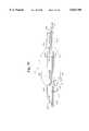
- FIG. 20is a side view, partially in section, of a preferred embodiment of a single-operator exchange catheter having a distal catheter shaft section;
- FIG. 21is a longitudinal sectional view of a distal portion of the catheter shown in FIG. 20;
- FIG. 22is a cross-sectional view along line 22--22 of FIG. 21;
- FIG. 23is a cross-sectional view along line 23--23 of FIG. 21;
- FIG. 24is a longitudinal sectional view of a first alternative embodiment of the distal portion of the catheter shown in FIG. 20;
- FIG. 25is a longitudinal sectional view of a second alternative embodiment of the distal portion of the catheter shown in FIG. 20;
- FIG. 26is a longitudinal sectional view of a third alternative embodiment of the distal portion of the catheter shown in FIG. 20;
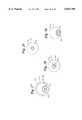
- FIG. 27is a cross-sectional view taken along line A--A in FIGS. 24, 25 and 26;
- FIG. 28is a cross-sectional view taken along line B--B in FIG. 24;
- FIG. 29is a cross-sectional view taken along line C--C in FIG. 25.
- FIG. 30is a cross-sectional view taken along line D--D in FIG. 26.
- the intravascular apparatus 10includes a balloon dilation catheter 12 having an elongated shaft 14.
- a proximal portion 16 of the shaft 14is adapted to extend outside the body of a patient during use, and a distal portion 18 of the shaft 14 is positionable intravascularly during use by manipulation of the proximal portion 16.
- a dilation balloon 20is located at and connected to the distal portion 18 of the catheter shaft 14.
- the balloon 20can be formed from a polyolefin copolymer or other polymer material such as polyether-block-amide.
- the balloon 20is formed of a polyolefin copolymer (such as that sold by DuPont under the tradename SURLYN as Resin No. 8527) using secondary treatment with 5 to 50 Mega-rad electron beam irradiation to enhance strength in the region of the balloon 20.
- the balloon 20has a proximal neck portion 22 defining a proximal opening 24, and a distal neck portion 26 defining a distal opening 28.
- the proximal neck portion 22preferably has an outer diameter of about 0.040 inches and an inner diameter of about 0.034 inches.
- the distal neck portion 26preferably has an outer diameter of about 0.030 inches and an inner diameter of about 0.025 inches.
- the distal portion 18 of the shaft 14extends into the proximal opening 24 in the balloon 20 and is preferably connected to the proximal neck portion 22.
- the shaft 14includes an inflation lumen 30 extending therethrough and has a proximal opening 32 and a distal opening 34.
- a manifold 36is connected to the proximal portion 16 of the shaft 14 and the dilation balloon 20 is in fluid flow communication with the inflation lumen 30. Inflation fluid is conveyed via the lumen 30 from the manifold 36 to inflate the balloon 20 and therefore dilate a vessel in a conventional manner known in the art.
- the shaft 14has a length of approximately 135 cm.
- the proximal portion 16 of the shaft 14is preferably made of stainless steel hypodermic tubing and the distal portion 18 is made of a relatively flexible polymeric material such as a polyolefin copolymer or polyethylene.
- This type of shaftis disclosed in U.S. patent application Ser. No. 07/833,099, filed Feb. 10, 1992, now abandoned, the disclosure of which is specifically incorporated herein by reference.
- the shape of the shaft 14 and lumen 30converges from a circular cross-section at the proximal portion 16 thereof (FIG. 3) to a kidney-shaped cross section at the distal portion thereof (FIGS. 4-6).
- An upper wall 38 and a lower wall 40 of the shaft 14converge distally of the distal opening 34 in the lumen 30 and extend across the balloon 20 to a position adjacent the distal neck portion 26 of the balloon 20.
- a stiffening wire 42extends distally from a distal end of the steel tubing and is attached to a distal end of the balloon 20 as disclosed in the No. '113 patent to provide additional support for the manipulation of the catheter 12.
- the stiffening wire 42can be attached to an underside of the upper wall 38 of the shaft and extend to approximately the center of the balloon 20 as shown in FIGS. 1 and 2.
- an elongated guide tube 44is adapted to extend through the proximal and distal openings 24 and 28 of the balloon 20 for slidable movement relative to the balloon 20 during use.
- the guide tube 44also has an inner chamber 50 extending therethrough from a proximal end 52 to a distal end 53 thereof for slidably receiving a conventional guide wire 54.
- the guide tube 44has a sufficient length, preferably about 135 cm, so that a proximal portion 46 of the guide tube 44 can extend outside the body of a patient during use while a distal portion 48 extends distally of the balloon 20.
- the guide tube 44is approximately the same length as a conventional catheter.
- the guide tube 44may also be provided in different sizes to accommodate different size devices.
- the guide tube 44can be provided with an inner diameter of 0.017 inches and an outer diameter of 0.020 inches for use with a 0.014 inch guide wire.
- the guide tube 44may be provided with an inner diameter of 0.013 inches and an outer diameter of 0.016 inches.
- the guide tube 44is made of a polymeric material, such as polyimide, and has a low friction coating, such as Teflon®, on both the inner and outer surfaces thereof.
- a coating on the inner surfaceenhances guide wire movement through the chamber 50, and a coating on the outer surface enhances movement of the guide tube 44 through a guiding catheter, a vessel, or the balloon 20.
- the guide tube 44can be made of other materials, such as polyurethane, polyester, or other polymers.
- the guide tube 44can also be made of a polyimide-teflon composite material, or reinforced with wire or a braid of metal or plastic or other materials.
- the pitch of a wound reinforcing wirecan be varied a desired amount along the length of the guide tube 44.
- the variable pitch wirecan provide increased stiffness at the proximal portion 46 of the guide tube 44 to facilitate manipulation of the entire guide tube 44.
- the variable pitch wirecan also provide sufficient flexibility at the distal portion 48 of the guide tube 44 to allow the guide tube 44 to easily follow the guide wire 54 through a vessel.
- the coatingsmay be made of other materials such as a hydrophilic or silicone coating.
- a metallic or foil coatingmay also be incorporated on the inner or outer surface of the guide tube 44.
- the guide wire 54has a sufficient length, preferably about 160-190 cm, so that a proximal portion 56 of the guide wire 54 can extend outside the body of a patient from an opening in the proximal end 52 in the guide tube 44 while a distal portion 58 extends distally from an opening in the distal end 53 of the guide tube 44.
- the proximal portion 56 of the guide wire 54can also extend out of an opening in the guide tube located distally of the proximal end 52 of the guide tube 44.
- the guide wire 54can have an outer diameter between 0.008 and 0.022 inches, although conventional guide wires typically have a diameter of 0.010, 0.014 or 0.018 inches.
- a proximal seal member 62is sealingly connected to the proximal neck portion 22 of the balloon 20 and a distal seal member 64 is sealingly connected to the distal neck portion 26 of the balloon 20.
- the proximal and distal seal members 62 and 64have passageways 66 and 68 therethrough for slidably receiving the guide tube 44.
- the seal members 62 and 64are preferably configured as collars and are made of a polymeric material, such as polyimide, polyurethane, polyester or the like.
- An upper portion of the proximal seal member 62is attached to the curved bottom wall 40 of the catheter shaft 14, and a lower portion is attached to the proximal neck portion 22 of the balloon 20.
- the entire periphery of the distal seal member 64is attached to the distal neck portion 26, and a distal end 70 of the shaft 14 is attached to a top portion of the distal seal member 64 proximally of the neck portion 26.
- the distal portion 48 of the guide tube 44is adapted to extend distally from an end 71 of the distal seal member 64 while the proximal portion 46 is outside the body of a patient.
- the outer diameter of the guide tube 44is only slightly smaller than the inner diameters of the proximal and distal seal members 62 and 64 to create a tolerance fit which allows slidable movement of the guide tube 44 through the seal member passageways 66 and 68.
- the tolerance fit between the guide tube 44 and the proximal and distal seal members 62 and 64inhibits inflation fluid from exiting the balloon 20.
- the distal seal member 64preferably extends proximally into the balloon 20 and has an expandable, tubular valve member 72 made of an elastomeric material such as TECOTHANE or the like. As shown in dashed lines in FIG. 2, the valve member 72 expands radially inward against the guide tube 44 when the balloon 20 is inflated to further seal any space between the guide tube 44 and the distal seal member 64.
- a valve member of similar constructioncan also be incorporated into the proximal seal member 62 if desired.
- FIGS. 9-19illustrate alternative embodiments of the present invention. Since these embodiments are similar to the previously described embodiment, similar parts appearing in FIGS. 9-15 are represented by the same, corresponding reference numeral, except for the corresponding letter in the numerals of the latter.
- a pair of split O-ring type sealsare provided to prevent inflation fluid from exiting the balloon 20a.
- An upper portion of a proximal split O-ring 80is attached to the curved bottom wall 40a of the catheter shaft 14a, and a lower portion is attached to the proximal neck portion 22a of the balloon 20a.
- the entire periphery of a distal O-ring 82can be attached to the distal seal member 64a as shown in FIG. 9 or bonded directly to the distal neck portion 26a of the balloon 20.
- the split O-rings 80 and 82are preferably made of a relatively soft durometer urethane material or the like and can be pre-formed or molded into the balloon 20a.
- a polyurethane adhesive or the likecan be injected into a shaped mold temporarily positioned in the neck portion of the balloon 20a.
- the contact surfaces of the O-rings 80 and 82are shown as rounded surfaces, the O-rings can be formed in any desired shape to facilitate slidable movement of the guide tube 44a while providing an effective seal when the balloon 20a is inflated.
- the shape and material of the O-ringallows greater deformation as a result of pressure from the inflation fluid, which may provide a more effective seal.
- the "single point" contact of the proximal and distal O-rings 80 and 82 with the guide tube 44amay facilitate advancement and withdrawal of the catheter 12a over the guide tube 44a because the decreased contact area tends to reduce frictional forces acting on the guide tube 44a.
- the guide tube 44bis configured with an enclosed, deformable bladder-type sheath 84 surrounding a portion thereof.
- the sheath 84has a constant volume of fluid therein (not shown) and is approximately the same length as the distance between the proximal and distal seal members 62b and 64b of the balloon 20b.
- the guide tube 44bPrior to inflation of the balloon 20b, the guide tube 44b is advanced or withdrawn until proximal and distal end portions 86 and 88 of the sheath 84 are substantially aligned with the proximal and distal seal members 62b and 64b (FIG. 12).
- the sheath 84bcan be provided in the form of spaced apart proximal and distal sheaths 90 and 92 surrounding the guide tube 44c as shown in FIGS. 14 and 15.
- the distance between the sheaths 90 and 92is approximately the same as the distance between the seal members 62c and 64c.
- the sheaths 90 and 92are aligned with the corresponding seal members 62c and 64c prior to inflation of the balloon 20c (FIG. 14), and the inflation fluid displaces the fluid in the sheaths 90 and 92 outwardly to create a seal between the sheaths 90 and 92 and the corresponding seal members 62c and 64c.
- the seal memberscan be eliminated and the sheaths can be configured to bear directly against the corresponding neck portions of the balloon when displaced by the inflation fluid.
- a bladder-type valve memberwhich surrounds the guide tube 44 and expands when filled with fluid can provide an active seal.
- Valve members of this typeare disclosed in U.S. Pat. No. 5,085,636, issued Feb. 4, 1992, the disclosure of which is specifically incorporated herein by reference.
- Such a sealcould be activated by the inflation fluid which fills the balloon 20 or by a separate flow of fluid through a micro-tube connected to the bladder.
- the proximal and distal seal memberscan be configured to slidably receive and provide an effective seal around a guide wire without the use of a guide tube (see, e.g., FIG. 9A).
- One advantage of this configurationmay be the reduced profile of the balloon 20 resulting from the elimination of an inner tube inside the balloon 20.
- Such a configurationmay also facilitate the flow of a radiopaque dye solution which is typically introduced into the vessel after an angioplasty procedure to determine whether an acceptable blood flow has been established through the vessel.
- the proximal neck portion 22preferably has an outer diameter of about 0.036 inches and an inner diameter of about 0.030 inches.
- the distal neck portion 26preferably has an outer diameter of about 0.025 inches and an inner diameter of about 0.020 inches.
- FIGS. 16-19illustrate yet another embodiment of the present invention.
- the shaft 14dhas a relatively large diameter body portion 100 and a smaller diameter distal end portion 102 which extends through the proximal and distal openings 24d and 28d in the balloon 20d.
- the juncture of the body portion 100 and the distal end portion 102is defined by a tapered shoulder 103 adjacent the balloon 20d.
- the distal end portion 102 of shaft 14dis sealingly attached to the proximal and distal neck portions 22d and 26d of the balloon 20d.
- the balloon 20dis inflated by conveying fluid via the inflation lumen 30d of the shaft 14d through a plurality of openings 104 formed in the distal end portion 102 of the shaft.
- a portion of the guide tube 44dis movably positioned within a distal portion of the inflation lumen 30d of shaft 14d. Because the guide tube 44d is positioned within the reduced diameter shaft lumen 30d rather than outside the shaft 14d, the profile of catheter 12d is minimized to allow insertion into relatively small vessels.
- the constant outer diameter of the distal end portion 102 of the shaft 14dalso may provide a better joint between the balloon 20d and the shaft 14d.
- An opening 106is provided in the body portion 100 of the shaft 14d, preferably about 10-30 cm proximally from the balloon 20d, for receiving the guide tube 44d.
- the guide tube 44dis guided by an inner core 108 which extends distally a relatively short distance, preferably about 5-15 mm, into the inflation lumen 30d from the opening 106.
- An end portion 110 of the core 108is flared to direct the guide tube 44d into the core 108 when the guide tube 44d is inserted in a proximal direction through the distal end portion 102 of the shaft 14d.
- a seal member 110is sealingly connected to the core 108.
- the seal member 110is preferably a split O-ring type seal which is described in more detail above.
- a split O-ring type seal member 112can also be provided in the distal neck portion 26d for sealingly engaging the guide tube 44d.
- the opening 106 and core 108 of the shaft 14d, along with the seal members 110 and 112,can be configured to slidably receive a guide wire or other intravascular device without the use of the guide tube 44d.
- the elimination of the guide tubewould allow the shaft to be configured with a smaller outer diameter, thus reducing the profile of the catheter.
- the catheter 12includes a proximal tubular member 14, a transition tube 200, and a distal catheter shaft section 202.
- the distal catheter shaft section 202is preferably the only tubular member extending distally beyond the distal end of the transition tube 200 through the balloon 20 with a distal opening 204 at the distal end of the catheter 12.
- the distal catheter shaft section 202provides a lumen 206 for both slidably receiving the guide wire 54 (whether incorporating a guide tube or guide wire only) and for providing fluid communication for inflation fluid from the distal area of the transition tube 200 to the inside of balloon 20.
- the proximal tubular member 14includes at least one tubular section and has a lumen 208 extending therethrough.
- the proximal tubular member 14is preferably a stainless steel hypotube.
- the transition tube 200preferably has a proximal end 210 connected proximate to the distal end 212 of the proximal tubular member 14.
- the transition tube 200has a lumen 201 in fluid communication with the lumen 208 of the proximal tubular member 14.
- the transition tube 200further includes a radial port 214.
- the radial port 214is created by boring a hole or otherwise forming a passage through the side wall of the transition tube 200.
- the proximal tubular member 14 and transition tube 200could be a single tubular member or main tubular member and thus the radial port 214 would be through the side wall of the main tubular member 14.
- the distal catheter shaft section 202has a proximal end 216 connected to the radial port 214.
- a lumen 206extends through the distal catheter shaft section 202 and extends distally beyond the distal end 218 of the transition tube 200 to the distal end 204 of the catheter 12.
- the distal end 218 of the transition tube 200is sealingly connected to the outside surface of the distal catheter shaft section 202.
- the transition tube 200 and distal catheter shaft section 202are preferably manufactured from a polymer such as polyethylene. Bonds between these polymeric tubular members are preferably accomplished through thermal welding, however it is recognized that adhesives may also be utilized as described for previous embodiments.
- the distal catheter shaft section 202further includes at least one first inflation hole 220 which extends through the wall thereof intermediate between the radial port 214 and the distal end 218 of the transition tube 200.
- the balloon 20has a proximal end 230 and a distal end 232 sealingly connected to the distal catheter shaft section 202 at a location spaced distally from the distal end 218 of the transition tube 200.
- the distal catheter shaft section 202further includes at least one second inflation hole 222 through the wall thereof intermediate the ends of the balloon 230, 232.
- the lumen 201 of the transition tube 200is in fluid communication with the interior of the balloon 20 through the first inflation hole 220, a portion of the lumen 206 of the distal catheter shaft section 202 and the second inflation hole 222.
- a core member 234can be disposed within the lumens 208, 201 of the proximal tubular member 14 and the transition tube 200 over at least a portion of their lengths.
- the core member 234is preferably a stainless steel wire.
- the core member 234extends from proximate the distal end 212 of the proximal tubular member 14 distally to a point proximate the radial port 214.
- a single tubular membernamely the distal catheter shaft section 202, eliminates the need for a separate guide wire lumen and inflation lumen from a point proximal to the balloon through the balloon
- the profile of a catheter designed in accordance with this embodimentis smaller and allows for better access to smaller vessels and better flow of fluid around the catheter 12, such as blood or radiopaque contrast fluid.
- means for sealing around the guide wire disposed within the lumen 206 of the distal catheter shaft section 202are provided. As with previous embodiments, many combinations of seals are possible.
- a first 240 and a second 242 active seal meansare provided for limiting the egress of inflation fluid.
- the first active seal means 240is disposed within the lumen 206 of the distal catheter shaft section 202 between the radial port 214 and the first inflation hole 220. This seal prevents or reduces leakage of inflation fluid out the port 214.
- the second active seal means 242is disposed within the lumen 206 of the distal catheter shaft section 202 between the distal end 204 of the catheter and the second inflation hole 222. This seal prevents or reduces leakage out the distal end of the catheter.
- the active seal means 240, 242are preferably sections of flexible tubing extending across a gap in the length of the distal catheter shaft section 202.
- a preferable material of constructionis and elastomeric material such as TECOTHANE or PEBA.
- first 240 and second 242 active seal meanscould incorporate an elastomeric material which extends across a gap in the length of the distal catheter shaft section 202 and be connected to the inside surface of the distal catheter shaft section 202.
- a pressure permeable, longitudinally stiff membercan be extended over the gap and affixed to the outside surface of the distal catheter shaft on each side of the gap. The pressure permeable, longitudinally stiff member can provide additional stiffness in the region of the active seals which can assist pushability of the catheter 12.
- First and second passive seal means 244, 246can also be included, as depicted in FIGS. 20-21.
- the passive sealsassist the active seals in preventing or reducing the egress of inflation fluid.
- the first passive seal means 244is disposed within the lumen 206 of the distal catheter shaft section 202 between the radial port 214 and the first inflation hole 220.
- the second passive seal 246is also disposed within the lumen 206 of the distal catheter shaft section 202, however, between the distal end 204 of the catheter 12 and the second inflation hole 222.
- the passive seal meansare preferably O-ring seals manufactured from a polymeric material such as polyurethane resin. Other manufacturing molding materials and methods may be utilized.
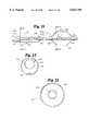
- FIGS. 24-30show alternative embodiments including a perfusion tube which permits blood to pass across the treatment site while the balloon is inflated.
- the alternative embodiments shown in FIGS. 24-30are substantially the same as the embodiment described with reference to FIGS. 20 and 21 with the following exceptions.
- the methods of useare also substantially the same except that prolonged balloon inflation may be possible given the incorporation of blood perfusion capabilities.
- Distal portion 300includes a perfusion tube 301 traversing the interior of the balloon 20.
- the perfusion tube 301allows blood to continue to flow across the treatment site when the balloon 20 is inflated.
- the perfusion tube 301permits blood to enter the perfusion inlet 303, flow through the perfusion lumen 309 and exit the perfusion outlet 304.
- the perfusion outlet 304may be laterally facing holes (as shown in FIG. 24) or a distally facing opening (as shown in FIG. 25) or a combination thereof.
- the perfusion tube 301includes a proximal section which is crimped into a partial crescent shape as best shown in FIG. 27.
- the perfusion tube 301returns to a circular cross-section distal of the seal 305 as best shown in FIG. 28.
- FIGS. 27 and 28show cross-sectional views taken at A--A and B--B respectively in FIG. 24.
- the distal shaft 202may be adhesively secured in the recess of the crimped portion of the perfusion tube 301.
- the proximal balloon waist 230is adhesively secured to both the distal shaft 202 and the crimped portion of the perfusion tube 301 to provide a sealed connection.
- the distal balloon waist 232may be adhesively secured to the distal portion of the perfusion tube 301.
- the distal end of the distal shaft 202may be adhesively secured to the distal end of the perfusion tube 301 distal of the perfusion outlet holes 304.
- the adhesive 308 used to connect the distal end of the distal shaft 202 to the distal end of the perfusion tube 301may be tapered in the distal direction to provide a smooth transition.
- the distal shaft 202includes a series of distal inflation holes 222 to provide a fluid path into the interior of the balloon.
- a distal guide wire seal 305is mounted to the distal end of the distal shaft section 202 distal of the inflation holes 222.
- the distal shaft section 202continues past the seal 305, traverses through the perfusion tube adjacent the distal end of the crimp 302 and extends to the distal end of the perfusion tube 301.
- the distal shaft section 202may be adhesively secured and sealed to the perfusion tube 301 adjacent the distal end of the crimp 302.
- perfusion tube 301could retain its circular shape along its entire length.
- Distal shaft 202may be contained within the interior of perfusion tube 301. Distal shaft 202 would be attached to the inner surface of perfusion tube 301 in at least one location. At least two access holes through the wall of perfusion tube 301 would be utilized; one to communicate inflation medium to the seal 305, and the other to communicate inflation media to the balloon.
- the distal seal 305may utilize an active seal 306 in combination with an o-ring passive seal 307.
- the arrangement of the o-ring seal 307 and the active seal 306is different from the arrangement discussed with reference to FIGS. 20 and 21, the same dimensions, materials and operating principles apply.
- the seal arrangement 305 as shown in FIG. 24may incorporate integrally formed active 306 and passive 307 seals made of a polymer such as TECOTHANE and formed by a molding process.
- FIG. 25shows a second alternative embodiment 310 of the distal portion of the catheter shown in FIG. 20.
- the second alternative embodiment 310 of the distal portionis identical to the first alternative embodiment 300 with the following exceptions.
- the distal shaft section 202 in the second embodiment 310terminates at the distal end of the crimp 302 and is adhesively secured thereto. This provides a larger perfusion lumen 309 distal of the seal 305.
- the increase in cross-sectional area of the perfusion lumen 309is best shown in FIG. 29 as compared to FIG. 28.
- FIGS. 27 and 29show cross-sectional views taken at A--A and C--C respectively in FIG. 25.
- the perfusion outlet 314is a distally facing opening since the distal end of the perfusion tube 301 cannot be bonded to the distal end of the distal shaft section 202.
- FIG. 26shows a third alternative embodiment 320 of the distal portion of the catheter shown in FIG. 20.
- the third alternative embodiment 320 of the distal portionis identical to the first alternative embodiment 300 with the following exceptions.
- the third alternative embodiment 320incorporates a perfusion tube 321 which is crimped into a partial crescent shape along its entire length.
- FIGS. 27 and 30show cross-sectional views taken at A--A and D--D respectively in FIG. 26.
- the distal shaft 202is disposed in the recess of the crimp and is bonded at its distal end to the distal balloon waist 232 and the distal end of the perfusion tube 321 in a similar manner as the proximal balloon waist 230 bond site. Blood enters the perfusion tube 321 at the perfusion inlet 323, flows through the perfusion lumen 309 and exits at the distally facing perfusion outlet 324.
- a first heat-activated seal embodimentincorporates a coil made of a shape memory alloy disposed about a flexible polymer tube.
- the flexible polymer tubemay be rigidly connected to the shaft such that a guide wire may pass through the lumen of the tube.
- the shape memory coilmay be disposed about the exterior of the polymer tube or embedded in the wall of the tube.
- the shape memory coilresponds to elevated temperatures by contracting radially and longitudinally.
- the radial contractioncompresses the polymeric tube onto the guide wire and forms a seal therebetween.
- the elevated temperaturemay be achieved by ohmic heating due to electrical currents passing through the shape memory coil.
- the electrical currentsin turn, may be induced by a primary coil outside the body or by direct electrical connection using wire leads extending through the catheter.
- a second heat-activated seal embodimentutilizes a shape memory polymer with a glass transition temperature above human body temperature.
- the shape memory polymermay be formed in the shape of a tube with a guide wire lumen extending therethrough.
- the mechanical strength of the shape memory polymervaries substantially across the glass transition temperature.
- the diameter of the guide wire lumenshould be slightly smaller than the diameter of the guide wire when the shape memory polymer is at room temperature.
- a heating element(such as an electrical coil made of heater wire) is used to heat the shape memory polymer at or near the glass transition temperature.
- the shape memory polymerincreases in size and becomes relatively soft at the elevated temperature, thus allowing the guide wire to move freely therethrough. The shape memory polymer is maintained at that temperature while the catheter is manipulated over the guide wire.
- a preferred shape memory polymeris MM-5520 polyurethane available from Mitsubishi having a glass transition temperature of about 55° C.
- lubricious coatingsmay be applied to any of the seals to reduce the friction between the seal and the guide wire passing therethrough. Substantially reducing the friction between the guide wire and the seal may eliminate the need to use an active seal, since a passive interference fit seal may be made substantially tighter without compromising guide wire movement.
- a ceramic coatingmay be applied to an elastomeric seal interference fit seal to provide free guide wire movement. The ceramic coating has been demonstrated to reduce friction of elastomeric materials by a factor ranging from 3 to 15. Spire Corporation has the capability of coating silicon rubber sheets with such a ceramic material and may be a suitable vendor for coating the guide wire seals discussed herein.
- intravascular accessis initially made in a conventional manner. If the procedure is a percutaneous translumenal angioplasty (PTCA) procedure, access is made via the femoral artery.
- PTCApercutaneous translumenal angioplasty
- a conventional introducer and guiding cathetercan be employed in a manner that is well known in the art.
- a guiding cathetershould have a lumen of sufficient size to accommodate the catheter 12, guide tube 44 and guide wire 54.
- the guide wire 54is preferably inserted into the guide tube 44 while the entire guide tube is outside the body such that the distal tip portion 58 of the guide wire 54 extends beyond the guide tube 44.
- the combination of the guide wire 54 and guide tube 44is then advanced to a desired location in a vessel, and the catheter 12 is advanced over the guide tube 44.
- the guide wire 54can be inserted into the vessel prior to advancement of the guide tube 44 over the guide wire, or the guide tube 44 can be inserted into the vessel prior to advancement of the guide wire 54 through the guide tube 44. If the catheter 12 is configured to receive the guide wire 54 without the guide tube 44, the guide wire 54 can be advanced to a desired location in a vessel in a "bare wire" technique and the catheter 12 can be passed over the guide wire 54.
- the combination guide wire 54 and guide tube 44are advanced until the distal portions 48 and 58 thereof reach a distal end of the guiding catheter.
- the guide wire 54may be further advanced in the vessel alone, or the guide tube 44 may be advanced along with the guide wire 54.
- the distal portion 48 of the guide tube 44can provide additional support for the distal portion 58 of the guide wire 54 when desired.
- the guide tube 44can then be advanced to support the guide wire 54 and assist its advancement in the vessel.
- using the guide tube 44may avoid having to exchange the guide wire 54 for another guide wire having a larger diameter.
- the guide tube 44is advanced until the distal end 53 reaches a distal end 60 of the guide wire 54.
- the guide wire 54is withdrawn from the guide tube 44, and a desired bend can be formed in the distal portion 58 of the guide wire 54 or another guide wire can be obtained.
- the newly configured guide wireis then advanced through the guide tube 44 to the previously attained position.
- the guide tube 44can also be used to straighten a bend in the distal portion 58 of the guide wire 54 while inside a vessel.
- the distal portion 58 of the guide wire 54is often bent a desired amount prior to insertion into the body of a patient to allow manipulation of the guide wire 54 through various vessels.
- the distal portion 58 of the guide wire 54may also bend as a result of advancement of the guide wire 54 when movement of the distal tip is impeded in the vessel. If the bend is inappropriate for further advancement of the guide wire 54 to the desired location in the vessel or for advancement into a different vessel, the guide tube 44 can be advanced over the guide wire 54 to straighten the distal portion 58 a desired amount.
- the guide tube 44can be advanced over the guide wire 54 after the guide wire is advanced past a stenosis in the vessel to pre-dilate the stenosis before insertion of the balloon 20.
- the guide wire 54can also be moved within the guide tube 44 when the balloon 20 is inflated inside a vessel.
- a substantial portion of the guide tube 44 and guide wire 54is positioned outside the catheter shaft 14 to allow a single-operator exchange of the catheter 12 for a second catheter.
- the catheter 12is withdrawn so that the balloon 20 passes over the guide tube 44 while an operator maintains a hold on the proximal portion 46 of the guide tube 44 and the proximal portion 56 of the guide wire 54.
- the balloon of a second cathetercan then be advanced over the guide tube 44 to position the second catheter in the same location previously attained by the first balloon catheter 12.
- This single-operator exchange type configurationallows the operator to maintain a hold on the guide tube 44 and guide wire 54 without using an extension or a relatively long guide tube and guide wire.
- the guide tube 44therefore provides for the independent or substantially contemporaneous exchange of the guide wire 54 and the catheter 12.
- the guide wire 54is withdrawn through the guide tube 44 and replaced with a second guide wire.
- the guide wire 54can be exchanged before the catheter 12 has been inserted in the vessel, while the catheter 12 remains in the vessel, or after the catheter 12 has been withdrawn.
- the catheter 12can be exchanged while the guide wire 54 remains in the vessel or after the guide wire 54 has been withdrawn. In either procedure, the position of the guide tube 44 is maintained in the vessel by holding onto the proximal portion 46 of the guide tube.
Landscapes
- Health & Medical Sciences (AREA)
- Heart & Thoracic Surgery (AREA)
- Life Sciences & Earth Sciences (AREA)
- Anesthesiology (AREA)
- Child & Adolescent Psychology (AREA)
- Biophysics (AREA)
- Pulmonology (AREA)
- Engineering & Computer Science (AREA)
- Vascular Medicine (AREA)
- Biomedical Technology (AREA)
- Hematology (AREA)
- Animal Behavior & Ethology (AREA)
- General Health & Medical Sciences (AREA)
- Public Health (AREA)
- Veterinary Medicine (AREA)
- Media Introduction/Drainage Providing Device (AREA)
Abstract
Description
This application is a continuation-in-part of U.S. patent application Ser. No. 08/204,988, filed Mar. 2, 1994, now Pat. No. 5,490,837, which is a continuation-in-part of U.S. patent application Ser. No. 08/055,695, now abandoned, filed Apr. 29, 1993, which is a continuation-in-part of U.S. patent application Ser. No. 07/725,064, now Pat. No. 5,281,203, filed Jul. 5, 1991, and U.S. patent application Ser. No. 07/843,647, now abandoned, filed Feb. 28, 1992, the entire disclosures of which are specifically incorporated herein by reference.
The present invention relates generally to methods and devices used in intravascular therapeutic and diagnostic procedures, and more particularly, to a method and apparatus for performing a balloon angioplasty procedure.
Intravascular catheterization devices have proven to be useful and efficient for both therapeutic and diagnostic purposes. Intravascular therapeutic techniques, such as angioplasty, atherectomy, and laser irradiation, have been developed as alternatives to bypass surgery for treating vascular diseases or other conditions that occlude or reduce the lumen size of portions of a patient's vascular system. In particular, balloon angioplasty has proven to be a useful and in many circumstances a preferred treatment for obstructive coronary diseases. Also, intravascular diagnostic techniques, such as ultrasonic imaging and Doppler blood flow measurements, have been developed to measure or image the extent of an occlusion of a vessel (e.g., stenosis). The devices used to perform the aforementioned intravascular therapeutic and diagnostic techniques may be used together or in conjunction with more invasive techniques such as coronary surgery.
These intravascular therapeutic and diagnostic devices have achieved acceptance because of their effectiveness as well as the fact that they can be used in a minor surgical procedure that is relatively nondisruptive to the patient compared to coronary surgery. These devices rely on the positioning of a catheter into the vascular system of a patient via an incision at an accessible location which may be remote from the site of the occlusion or stenosis. For example, the accessible location may be the femoral artery at the groin. The intravascular device is then advanced through the incision via the femoral artery to a desired distal site. The distal sites into which the device may be advanced include the coronary arteries, branch vessels stemming from the external carotid artery such as the occipital and the arteries leading to the vessels of the head and brain, splenic, and the inferior mesenteric and renal arteries leading to the organs of the thorax as well as other vessels.
Because of the small size of some of these vessels and the tortuous passages through the vessels, positioning of a catheter device through a patient's vasculature can be a difficult and time consuming task requiring considerable skill on the part of the physician. For example, in order to perform an angioplasty dilation, the angioplasty balloon catheter must be positioned across the stenosis in the arterial site. The stenosis may be located in a tortuous portion of the coronary vasculature and, furthermore, the obstructive arterial disease may impede crossing the stenosis with the balloon portion of the angioplasty catheter. Thus, not all arterial obstructions can be successfully treated by present intravascular balloon catheter procedures because some arterial obstructions are not readily accessible to a balloon dilation catheter. Accordingly, there is often a need for intravascular catheters of very low profile that can be positioned in narrow, tortuous regions of a person's vasculature.
Another important consideration relating to intravascular procedures, such as angioplasty, relates to the exchange of various devices used to perform the procedures. Intravascular therapeutic and diagnostic devices come in various types and sizes suitable for the vessel size and location in which the treatment is to be performed. Sometimes, it becomes necessary to exchange a first therapeutic device for one of a different size after an unsuccessful attempt has been made to position the first device in the appropriate location. It may also become necessary to exchange therapeutic devices after the first device is successfully positioned in the desired location. This may be necessitated because it becomes apparent that the first device is the wrong size or configuration, or because it is determined that additional therapeutic or diagnostic procedures with a different size or type of device is required.
Several different types of catheter constructions have been developed for positioning intravascular therapeutic or diagnostic catheters through a patient's vasculature. One type of catheter design, commonly referred to as a fixed-wire type catheter, includes a non-removable wire with a flexible spring tip attached to a distal end of the intravascular catheter. The spring tip facilitates maneuvering the catheter to the desired vessel site. A disadvantage of the fixed-wire type catheter is that if it becomes necessary to exchange a first catheter for a second catheter, the maneuvering procedure must be repeated for the second catheter. As mentioned above, this can sometimes be a tedious and difficult procedure.
Another type of catheter design, referred to as an over-the-wire type catheter, includes a central lumen through the intravascular device that can accommodate a separate guide wire that is movable, and removable, in relation to the catheter to facilitate positioning the catheter in a remote vessel location over the guide wire. In the over-the-wire construction, the catheter typically includes a lumen adapted to receive the guide wire from a proximal end to the distal end of the device. The guide wire is initially loaded through the lumen of the over-the-wire catheter and extends out from the distal end thereof. Then, the guide wire and the intravascular catheter are advanced together and positioned in the vessel at the desired site. The guide wire may be advanced distally of the distal end of the catheter and steered, as necessary, to traverse tortuous passages of the vessel. The guide wire may then be withdrawn proximally through the lumen of the catheter or may be left in place extending from the distal end of the catheter during the procedure.
The over-the-wire type intravascular catheter facilitates exchanges because a first catheter can be exchanged for a second catheter without removing the guide wire. This allows an exchange of catheters without having to repeat the difficult and time consuming task of positioning the guide wire across the treatment site. In order to leave the distal end of the guide wire in place, it is preferred to maintain a hold on a proximal end portion of the guide wire during the exchange operation. One way to maintain such a hold is to use a guide wire having a sufficiently long length (e.g., 300 cm) so that the entire catheter can be completely withdrawn over the guide wire while maintaining a hold on a portion of the wire. A disadvantage of this method is that the long proximally extending portion of the guide wire may be in the way during the procedure. Another way to maintain a hold on a portion of the guide wire during an exchange operation is to use a guide wire extension. A disadvantage of this method is that not all guide wires are adapted to connect to an extension wire, and moreover, the step of connecting the guide wire to the extension wire can sometimes be tedious and difficult to perform.
A variation of the over-the-wire type catheter which facilitates the exchange of a first catheter with a second catheter is the single-operator exchange type construction. With the single-operator exchange type construction, a guide wire occupies a position adjacent and exterior to the intravascular catheter along proximal and middle portions of the catheter and enters into a short guide wire lumen of the catheter via an opening at a location close to a distal portion of the catheter. With this type of construction, the catheter can be positioned in the patient's vessel by positioning a guide wire in the desired location and advancing the catheter device over the wire. However, in the event it becomes necessary to exchange the catheter, the position of the guide wire can be maintained during withdrawal of the catheter without the use of a long guide wire (e.g., 300 cm) or an extension wire. Because the proximal end of the guide wire is exterior to the proximal end of the catheter, the proximal end of the guide wire can be held during withdrawal of the catheter so that the position of the distal end of the guide wire in the patient's vessel can be maintained. With this type of catheter, it is necessary that the distance from the distal end of the catheter to the proximal guide wire lumen entrance is less than the length of the guide wire that extends proximally out of the patient.
With known single-operator exchange type constructions, a catheter has at least one lumen extending over substantially the entire length of the catheter and a second guide wire lumen which begins at a location close to a distal portion of the catheter, usually proximal of the balloon and extending distally through the balloon, and opening at the distal end of the balloon. The additional lumen, and associated structure to form such lumen, impact the profile of the catheter in its distal region. This also impacts the flexibility and pushability of the catheter.
It is desirable to minimize the profile of the catheter in the distal region in order to more easily navigate through vascular restrictions. It is also desirable to maximize flexibility and trackability in order to better navigate through tortuous vasculature. It is further desirable to provide a means for blood perfusion during balloon dilation in order to minimize ischemic reaction.
In summary, the present invention may be described as a balloon dilation catheter including an elongate shaft with an inflatable balloon connected to the distal end. The catheter includes a proximal guide wire port and seal combination and a distal guide wire port and seal combination providing access for a guide wire to extend through the distal portion of the shaft and the balloon. The catheter further includes a blood perfusion tube passing through the interior of the balloon.
The present invention, together with further objects and advantages, will be best understood by reference to the following detailed description taken in conjunction with the accompanying drawings.
FIG. 1 is a side view, partially in section, of a preferred embodiment of a balloon dilation catheter of the present invention;
FIG. 2 is a longitudinal sectional view of a distal portion of the catheter shown in FIG. 1;
FIG. 3 is a cross-sectional view of the catheter taken along theline 3--3 in FIG. 1;
FIG. 4 is a cross-sectional view of the catheter taken along theline 4--4 in FIG. 2;
FIG. 5 is a cross-sectional view of the catheter taken along theline 5--5 in FIG. 2;
FIG. 6 is a cross-sectional view of the catheter taken along theline 6--6 of FIG. 2;
FIG. 7 is a cross-sectional view of the catheter taken along theline 7--7 of FIG. 2;
FIG. 8 is a cross-sectional view of the catheter taken along theline 8--8 of FIG. 2;
FIG. 9 is a longitudinal sectional view of a second preferred embodiment of a balloon dilation catheter;
FIG. 9A is a longitudinal sectional view of an alternative embodiment of the catheter shown in FIG. 9;
FIG. 10 is a cross-sectional view of the second preferred embodiment taken along theline 10--10 in FIG. 9;
FIG. 11 is a cross-sectional view of the second preferred embodiment taken along the line 11--11 in FIG. 9;
FIG. 12 is a side view, partially in section, of a third preferred embodiment of a balloon dilation catheter showing a deflated balloon;
FIG. 13 is a side view, partially in section, of the embodiment in FIG. 12 showing an inflated balloon;
FIG. 14 is a side view, partially in section, of a fourth preferred embodiment of a balloon dilation catheter showing a deflated balloon;
FIG. 15 is a side view, partially in section, of the embodiment in FIG. 14 showing an inflated balloon;
FIG. 16 is a side view, partially in section, of a fifth preferred embodiment of a balloon dilatation catheter;
FIG. 17 is a cross-sectional view of the catheter taken along theline 17--17 in FIG. 16;
FIG. 18 is a cross-sectional view of the catheter taken along theline 18--18 in FIG. 16;
FIG. 19 is a cross-sectional view of the catheter taken along theline 19--19 in FIG. 16;
FIG. 20 is a side view, partially in section, of a preferred embodiment of a single-operator exchange catheter having a distal catheter shaft section;
FIG. 21 is a longitudinal sectional view of a distal portion of the catheter shown in FIG. 20;
FIG. 22 is a cross-sectional view alongline 22--22 of FIG. 21;
FIG. 23 is a cross-sectional view alongline 23--23 of FIG. 21;
FIG. 24 is a longitudinal sectional view of a first alternative embodiment of the distal portion of the catheter shown in FIG. 20;
FIG. 25 is a longitudinal sectional view of a second alternative embodiment of the distal portion of the catheter shown in FIG. 20;
FIG. 26 is a longitudinal sectional view of a third alternative embodiment of the distal portion of the catheter shown in FIG. 20;
FIG. 27 is a cross-sectional view taken along line A--A in FIGS. 24, 25 and 26;
FIG. 28 is a cross-sectional view taken along line B--B in FIG. 24;
FIG. 29 is a cross-sectional view taken along line C--C in FIG. 25; and
FIG. 30 is a cross-sectional view taken along line D--D in FIG. 26.
The presently preferred embodiments and methodology described herein are applicable to coronary angioplasty procedures and are specifically described in the context of dilation balloon catheters. It should be understood, however, that the embodiments and methodology of the present invention may be adapted for use with other types of intravascular therapeutic devices, such as atherectomy catheters, as well as diagnostic catheters, such as ultrasonic catheters.
Referring to FIG. 1, a first embodiment of a single-operator exchange type intravascular apparatus is indicated generally at 10. Theintravascular apparatus 10 includes aballoon dilation catheter 12 having anelongated shaft 14. Aproximal portion 16 of theshaft 14 is adapted to extend outside the body of a patient during use, and adistal portion 18 of theshaft 14 is positionable intravascularly during use by manipulation of theproximal portion 16.
Adilation balloon 20 is located at and connected to thedistal portion 18 of thecatheter shaft 14. Theballoon 20 can be formed from a polyolefin copolymer or other polymer material such as polyether-block-amide. For example, in one embodiment, theballoon 20 is formed of a polyolefin copolymer (such as that sold by DuPont under the tradename SURLYN as Resin No. 8527) using secondary treatment with 5 to 50 Mega-rad electron beam irradiation to enhance strength in the region of theballoon 20. Preferably, theballoon 20 has aproximal neck portion 22 defining aproximal opening 24, and adistal neck portion 26 defining adistal opening 28. Theproximal neck portion 22 preferably has an outer diameter of about 0.040 inches and an inner diameter of about 0.034 inches. Thedistal neck portion 26 preferably has an outer diameter of about 0.030 inches and an inner diameter of about 0.025 inches.
Thedistal portion 18 of theshaft 14 extends into theproximal opening 24 in theballoon 20 and is preferably connected to theproximal neck portion 22. Theshaft 14 includes aninflation lumen 30 extending therethrough and has aproximal opening 32 and adistal opening 34. A manifold 36 is connected to theproximal portion 16 of theshaft 14 and thedilation balloon 20 is in fluid flow communication with theinflation lumen 30. Inflation fluid is conveyed via thelumen 30 from the manifold 36 to inflate theballoon 20 and therefore dilate a vessel in a conventional manner known in the art.
In a preferred embodiment, theshaft 14 has a length of approximately 135 cm. Theproximal portion 16 of theshaft 14 is preferably made of stainless steel hypodermic tubing and thedistal portion 18 is made of a relatively flexible polymeric material such as a polyolefin copolymer or polyethylene. This type of shaft is disclosed in U.S. patent application Ser. No. 07/833,099, filed Feb. 10, 1992, now abandoned, the disclosure of which is specifically incorporated herein by reference. In order to minimize the profile of thedistal portion 18 ofshaft 14, the shape of theshaft 14 andlumen 30 converges from a circular cross-section at theproximal portion 16 thereof (FIG. 3) to a kidney-shaped cross section at the distal portion thereof (FIGS. 4-6). Anupper wall 38 and alower wall 40 of theshaft 14 converge distally of thedistal opening 34 in thelumen 30 and extend across theballoon 20 to a position adjacent thedistal neck portion 26 of theballoon 20. Preferably, astiffening wire 42 extends distally from a distal end of the steel tubing and is attached to a distal end of theballoon 20 as disclosed in the No. '113 patent to provide additional support for the manipulation of thecatheter 12. Alternatively, thestiffening wire 42 can be attached to an underside of theupper wall 38 of the shaft and extend to approximately the center of theballoon 20 as shown in FIGS. 1 and 2.
To facilitate the operation and exchange of the components of theintravascular apparatus 10, anelongated guide tube 44 is adapted to extend through the proximal anddistal openings balloon 20 for slidable movement relative to theballoon 20 during use. Theguide tube 44 also has aninner chamber 50 extending therethrough from aproximal end 52 to adistal end 53 thereof for slidably receiving aconventional guide wire 54. Theguide tube 44 has a sufficient length, preferably about 135 cm, so that aproximal portion 46 of theguide tube 44 can extend outside the body of a patient during use while adistal portion 48 extends distally of theballoon 20. Preferably, theguide tube 44 is approximately the same length as a conventional catheter.
Theguide tube 44 may also be provided in different sizes to accommodate different size devices. For example, theguide tube 44 can be provided with an inner diameter of 0.017 inches and an outer diameter of 0.020 inches for use with a 0.014 inch guide wire. For use with a 0.010 inch guide wire, theguide tube 44 may be provided with an inner diameter of 0.013 inches and an outer diameter of 0.016 inches.
Preferably, theguide tube 44 is made of a polymeric material, such as polyimide, and has a low friction coating, such as Teflon®, on both the inner and outer surfaces thereof. A coating on the inner surface enhances guide wire movement through thechamber 50, and a coating on the outer surface enhances movement of theguide tube 44 through a guiding catheter, a vessel, or theballoon 20. Alternatively, theguide tube 44 can be made of other materials, such as polyurethane, polyester, or other polymers. Theguide tube 44 can also be made of a polyimide-teflon composite material, or reinforced with wire or a braid of metal or plastic or other materials.
To provide greater stiffness at theproximal portion 46 of theguide tube 44 compared to thedistal portion 48, the pitch of a wound reinforcing wire can be varied a desired amount along the length of theguide tube 44. The variable pitch wire can provide increased stiffness at theproximal portion 46 of theguide tube 44 to facilitate manipulation of theentire guide tube 44. The variable pitch wire can also provide sufficient flexibility at thedistal portion 48 of theguide tube 44 to allow theguide tube 44 to easily follow theguide wire 54 through a vessel. Also alternatively, the coatings may be made of other materials such as a hydrophilic or silicone coating. In addition to or instead of the low friction coating, a metallic or foil coating may also be incorporated on the inner or outer surface of theguide tube 44.
Theguide wire 54 has a sufficient length, preferably about 160-190 cm, so that aproximal portion 56 of theguide wire 54 can extend outside the body of a patient from an opening in theproximal end 52 in theguide tube 44 while adistal portion 58 extends distally from an opening in thedistal end 53 of theguide tube 44. Theproximal portion 56 of theguide wire 54 can also extend out of an opening in the guide tube located distally of theproximal end 52 of theguide tube 44. In addition, theguide wire 54 can have an outer diameter between 0.008 and 0.022 inches, although conventional guide wires typically have a diameter of 0.010, 0.014 or 0.018 inches.
In a first embodiment, aproximal seal member 62 is sealingly connected to theproximal neck portion 22 of theballoon 20 and adistal seal member 64 is sealingly connected to thedistal neck portion 26 of theballoon 20. The proximal anddistal seal members passageways guide tube 44. Theseal members proximal seal member 62 is attached to thecurved bottom wall 40 of thecatheter shaft 14, and a lower portion is attached to theproximal neck portion 22 of theballoon 20. The entire periphery of thedistal seal member 64 is attached to thedistal neck portion 26, and adistal end 70 of theshaft 14 is attached to a top portion of thedistal seal member 64 proximally of theneck portion 26. In use, thedistal portion 48 of theguide tube 44 is adapted to extend distally from anend 71 of thedistal seal member 64 while theproximal portion 46 is outside the body of a patient. Preferably, the outer diameter of theguide tube 44 is only slightly smaller than the inner diameters of the proximal anddistal seal members guide tube 44 through theseal member passageways balloon 20 is inflated with fluid, the tolerance fit between theguide tube 44 and the proximal anddistal seal members balloon 20.
In addition, thedistal seal member 64 preferably extends proximally into theballoon 20 and has an expandable,tubular valve member 72 made of an elastomeric material such as TECOTHANE or the like. As shown in dashed lines in FIG. 2, thevalve member 72 expands radially inward against theguide tube 44 when theballoon 20 is inflated to further seal any space between theguide tube 44 and thedistal seal member 64. A valve member of similar construction can also be incorporated into theproximal seal member 62 if desired.
FIGS. 9-19 illustrate alternative embodiments of the present invention. Since these embodiments are similar to the previously described embodiment, similar parts appearing in FIGS. 9-15 are represented by the same, corresponding reference numeral, except for the corresponding letter in the numerals of the latter.
In the embodiment shown in FIGS. 9-11, a pair of split O-ring type seals are provided to prevent inflation fluid from exiting the balloon 20a. An upper portion of a proximal split O-ring 80 is attached to thecurved bottom wall 40a of the catheter shaft 14a, and a lower portion is attached to the proximal neck portion 22a of the balloon 20a. The entire periphery of a distal O-ring 82 can be attached to thedistal seal member 64a as shown in FIG. 9 or bonded directly to thedistal neck portion 26a of theballoon 20. The split O-rings
In a molding operation, a polyurethane adhesive or the like can be injected into a shaped mold temporarily positioned in the neck portion of the balloon 20a. Although the contact surfaces of the O-rings rings
In the embodiment shown in FIGS. 12-13, theguide tube 44b is configured with an enclosed, deformable bladder-type sheath 84 surrounding a portion thereof. Thesheath 84 has a constant volume of fluid therein (not shown) and is approximately the same length as the distance between the proximal anddistal seal members balloon 20b. Prior to inflation of theballoon 20b, theguide tube 44b is advanced or withdrawn until proximal anddistal end portions sheath 84 are substantially aligned with the proximal anddistal seal members balloon 20b is inflated with fluid, the fluid in thesheath 84 is displaced outwardly toward theend portions 86 and 88 (FIG. 13). As a result, the volume of space occupied by theend portions seal members balloon 20b.
Alternatively, the sheath 84b can be provided in the form of spaced apart proximal anddistal sheaths sheaths seal members sheaths corresponding seal members sheaths sheaths corresponding seal members
Alternatively, a bladder-type valve member which surrounds theguide tube 44 and expands when filled with fluid can provide an active seal. Valve members of this type are disclosed in U.S. Pat. No. 5,085,636, issued Feb. 4, 1992, the disclosure of which is specifically incorporated herein by reference. Such a seal could be activated by the inflation fluid which fills theballoon 20 or by a separate flow of fluid through a micro-tube connected to the bladder.
In any of the embodiments described herein, the proximal and distal seal members can be configured to slidably receive and provide an effective seal around a guide wire without the use of a guide tube (see, e.g., FIG. 9A). One advantage of this configuration may be the reduced profile of theballoon 20 resulting from the elimination of an inner tube inside theballoon 20. Such a configuration may also facilitate the flow of a radiopaque dye solution which is typically introduced into the vessel after an angioplasty procedure to determine whether an acceptable blood flow has been established through the vessel. When a 0.014 inch guide wire is used, theproximal neck portion 22 preferably has an outer diameter of about 0.036 inches and an inner diameter of about 0.030 inches. Thedistal neck portion 26 preferably has an outer diameter of about 0.025 inches and an inner diameter of about 0.020 inches. Thus, the distal and proximal seals inhibit fluid from exiting theballoon 20 without separating the movable guide wire from the inflation fluid in the balloon.
FIGS. 16-19 illustrate yet another embodiment of the present invention. In this embodiment, theshaft 14d has a relatively largediameter body portion 100 and a smaller diameterdistal end portion 102 which extends through the proximal anddistal openings balloon 20d. Preferably, the juncture of thebody portion 100 and thedistal end portion 102 is defined by atapered shoulder 103 adjacent theballoon 20d. Thedistal end portion 102 ofshaft 14d is sealingly attached to the proximal anddistal neck portions balloon 20d. Theballoon 20d is inflated by conveying fluid via theinflation lumen 30d of theshaft 14d through a plurality ofopenings 104 formed in thedistal end portion 102 of the shaft. Instead of slidably attaching theguide tube 44d to theballoon 20d and positioning theentire guide tube 44d outside theshaft 14d, a portion of theguide tube 44d is movably positioned within a distal portion of theinflation lumen 30d ofshaft 14d. Because theguide tube 44d is positioned within the reduceddiameter shaft lumen 30d rather than outside theshaft 14d, the profile ofcatheter 12d is minimized to allow insertion into relatively small vessels. The constant outer diameter of thedistal end portion 102 of theshaft 14d also may provide a better joint between theballoon 20d and theshaft 14d.
Anopening 106 is provided in thebody portion 100 of theshaft 14d, preferably about 10-30 cm proximally from theballoon 20d, for receiving theguide tube 44d. Theguide tube 44d is guided by aninner core 108 which extends distally a relatively short distance, preferably about 5-15 mm, into theinflation lumen 30d from theopening 106. Anend portion 110 of thecore 108 is flared to direct theguide tube 44d into thecore 108 when theguide tube 44d is inserted in a proximal direction through thedistal end portion 102 of theshaft 14d. To prevent fluid from exiting through thecore 108 and out theopening 106, aseal member 110 is sealingly connected to thecore 108. Theseal member 110 is preferably a split O-ring type seal which is described in more detail above. A split O-ringtype seal member 112 can also be provided in thedistal neck portion 26d for sealingly engaging theguide tube 44d.
Alternatively, theopening 106 andcore 108 of theshaft 14d, along with theseal members guide tube 44d. The elimination of the guide tube would allow the shaft to be configured with a smaller outer diameter, thus reducing the profile of the catheter.
Another preferred embodiment of a single-operator exchange catheter of the present invention is depicted in FIGS. 20-23. With this embodiment, thecatheter 12 includes a proximaltubular member 14, atransition tube 200, and a distalcatheter shaft section 202. The distalcatheter shaft section 202 is preferably the only tubular member extending distally beyond the distal end of thetransition tube 200 through theballoon 20 with adistal opening 204 at the distal end of thecatheter 12. By the use of active and/or passive seals and the configuration described below, the distalcatheter shaft section 202 provides alumen 206 for both slidably receiving the guide wire 54 (whether incorporating a guide tube or guide wire only) and for providing fluid communication for inflation fluid from the distal area of thetransition tube 200 to the inside ofballoon 20.
Theproximal tubular member 14 includes at least one tubular section and has alumen 208 extending therethrough. Theproximal tubular member 14, as with the embodiments described above, extends distally from a manifold 36. Theproximal tubular member 14 is preferably a stainless steel hypotube. As shown in FIG. 20, thetransition tube 200 preferably has aproximal end 210 connected proximate to the distal end 212 of theproximal tubular member 14. Thetransition tube 200 has alumen 201 in fluid communication with thelumen 208 of theproximal tubular member 14. Thetransition tube 200 further includes aradial port 214. Theradial port 214 is created by boring a hole or otherwise forming a passage through the side wall of thetransition tube 200. Although not preferable, theproximal tubular member 14 andtransition tube 200 could be a single tubular member or main tubular member and thus theradial port 214 would be through the side wall of the maintubular member 14.
The distalcatheter shaft section 202, as best depicted in FIG. 21, has aproximal end 216 connected to theradial port 214. Alumen 206 extends through the distalcatheter shaft section 202 and extends distally beyond thedistal end 218 of thetransition tube 200 to thedistal end 204 of thecatheter 12.
Thedistal end 218 of thetransition tube 200 is sealingly connected to the outside surface of the distalcatheter shaft section 202. Thetransition tube 200 and distalcatheter shaft section 202 are preferably manufactured from a polymer such as polyethylene. Bonds between these polymeric tubular members are preferably accomplished through thermal welding, however it is recognized that adhesives may also be utilized as described for previous embodiments.
The distalcatheter shaft section 202 further includes at least onefirst inflation hole 220 which extends through the wall thereof intermediate between theradial port 214 and thedistal end 218 of thetransition tube 200.
Theballoon 20 has aproximal end 230 and adistal end 232 sealingly connected to the distalcatheter shaft section 202 at a location spaced distally from thedistal end 218 of thetransition tube 200. The distalcatheter shaft section 202 further includes at least onesecond inflation hole 222 through the wall thereof intermediate the ends of theballoon
With the above structure, thelumen 201 of thetransition tube 200 is in fluid communication with the interior of theballoon 20 through thefirst inflation hole 220, a portion of thelumen 206 of the distalcatheter shaft section 202 and thesecond inflation hole 222.
Acore member 234 can be disposed within thelumens proximal tubular member 14 and thetransition tube 200 over at least a portion of their lengths. Thecore member 234 is preferably a stainless steel wire. In one embodiment, thecore member 234 extends from proximate the distal end 212 of theproximal tubular member 14 distally to a point proximate theradial port 214.
Because a single tubular member, namely the distalcatheter shaft section 202, eliminates the need for a separate guide wire lumen and inflation lumen from a point proximal to the balloon through the balloon, the profile of a catheter designed in accordance with this embodiment is smaller and allows for better access to smaller vessels and better flow of fluid around thecatheter 12, such as blood or radiopaque contrast fluid. To prevent leakage of inflation fluid proximal to thefirst inflation hole 220 and distal to thesecond inflation hole 222, means for sealing around the guide wire disposed within thelumen 206 of the distalcatheter shaft section 202 are provided. As with previous embodiments, many combinations of seals are possible.
In one embodiment, depicted in FIGS. 20-23, a first 240 and a second 242 active seal means are provided for limiting the egress of inflation fluid. The first active seal means 240 is disposed within thelumen 206 of the distalcatheter shaft section 202 between theradial port 214 and thefirst inflation hole 220. This seal prevents or reduces leakage of inflation fluid out theport 214. The second active seal means 242 is disposed within thelumen 206 of the distalcatheter shaft section 202 between thedistal end 204 of the catheter and thesecond inflation hole 222. This seal prevents or reduces leakage out the distal end of the catheter. The active seal means 240, 242 are preferably sections of flexible tubing extending across a gap in the length of the distalcatheter shaft section 202. A preferable material of construction is and elastomeric material such as TECOTHANE or PEBA.
In an alternative embodiment, the first 240 and second 242 active seal means could incorporate an elastomeric material which extends across a gap in the length of the distalcatheter shaft section 202 and be connected to the inside surface of the distalcatheter shaft section 202. With this design, a pressure permeable, longitudinally stiff member can be extended over the gap and affixed to the outside surface of the distal catheter shaft on each side of the gap. The pressure permeable, longitudinally stiff member can provide additional stiffness in the region of the active seals which can assist pushability of thecatheter 12.
First and second passive seal means 244, 246 can also be included, as depicted in FIGS. 20-21. The passive seals assist the active seals in preventing or reducing the egress of inflation fluid. The first passive seal means 244 is disposed within thelumen 206 of the distalcatheter shaft section 202 between theradial port 214 and thefirst inflation hole 220. The secondpassive seal 246 is also disposed within thelumen 206 of the distalcatheter shaft section 202, however, between thedistal end 204 of thecatheter 12 and thesecond inflation hole 222. The passive seal means are preferably O-ring seals manufactured from a polymeric material such as polyurethane resin. Other manufacturing molding materials and methods may be utilized.
FIGS. 24-30 show alternative embodiments including a perfusion tube which permits blood to pass across the treatment site while the balloon is inflated. The alternative embodiments shown in FIGS. 24-30 are substantially the same as the embodiment described with reference to FIGS. 20 and 21 with the following exceptions. The methods of use are also substantially the same except that prolonged balloon inflation may be possible given the incorporation of blood perfusion capabilities.
Refer to FIG. 24 which shows a firstalternative embodiment 300 of the distal portion of the catheter shown in FIG. 20.Distal portion 300 includes aperfusion tube 301 traversing the interior of theballoon 20. Theperfusion tube 301 allows blood to continue to flow across the treatment site when theballoon 20 is inflated. In particular, theperfusion tube 301 permits blood to enter theperfusion inlet 303, flow through theperfusion lumen 309 and exit theperfusion outlet 304. Theperfusion outlet 304 may be laterally facing holes (as shown in FIG. 24) or a distally facing opening (as shown in FIG. 25) or a combination thereof.
Theperfusion tube 301 includes a proximal section which is crimped into a partial crescent shape as best shown in FIG. 27. Theperfusion tube 301 returns to a circular cross-section distal of theseal 305 as best shown in FIG. 28. FIGS. 27 and 28 show cross-sectional views taken at A--A and B--B respectively in FIG. 24. Thedistal shaft 202 may be adhesively secured in the recess of the crimped portion of theperfusion tube 301. Theproximal balloon waist 230 is adhesively secured to both thedistal shaft 202 and the crimped portion of theperfusion tube 301 to provide a sealed connection. Thedistal balloon waist 232 may be adhesively secured to the distal portion of theperfusion tube 301. The distal end of thedistal shaft 202 may be adhesively secured to the distal end of theperfusion tube 301 distal of the perfusion outlet holes 304. The adhesive 308 used to connect the distal end of thedistal shaft 202 to the distal end of theperfusion tube 301 may be tapered in the distal direction to provide a smooth transition.
Thedistal shaft 202 includes a series of distal inflation holes 222 to provide a fluid path into the interior of the balloon. A distalguide wire seal 305 is mounted to the distal end of thedistal shaft section 202 distal of the inflation holes 222. Thedistal shaft section 202 continues past theseal 305, traverses through the perfusion tube adjacent the distal end of thecrimp 302 and extends to the distal end of theperfusion tube 301. Thedistal shaft section 202 may be adhesively secured and sealed to theperfusion tube 301 adjacent the distal end of thecrimp 302.
Alternatively,perfusion tube 301 could retain its circular shape along its entire length.Distal shaft 202 may be contained within the interior ofperfusion tube 301.Distal shaft 202 would be attached to the inner surface ofperfusion tube 301 in at least one location. At least two access holes through the wall ofperfusion tube 301 would be utilized; one to communicate inflation medium to theseal 305, and the other to communicate inflation media to the balloon.
Thedistal seal 305 may utilize anactive seal 306 in combination with an o-ringpassive seal 307. Although the arrangement of the o-ring seal 307 and theactive seal 306 is different from the arrangement discussed with reference to FIGS. 20 and 21, the same dimensions, materials and operating principles apply. It is contemplated theseal arrangement 305 as shown in FIG. 24 may incorporate integrally formed active 306 and passive 307 seals made of a polymer such as TECOTHANE and formed by a molding process.
Refer now to FIG. 25 which shows a secondalternative embodiment 310 of the distal portion of the catheter shown in FIG. 20. The secondalternative embodiment 310 of the distal portion is identical to the firstalternative embodiment 300 with the following exceptions.
Thedistal shaft section 202 in thesecond embodiment 310 terminates at the distal end of thecrimp 302 and is adhesively secured thereto. This provides alarger perfusion lumen 309 distal of theseal 305. The increase in cross-sectional area of theperfusion lumen 309 is best shown in FIG. 29 as compared to FIG. 28. FIGS. 27 and 29 show cross-sectional views taken at A--A and C--C respectively in FIG. 25. Theperfusion outlet 314 is a distally facing opening since the distal end of theperfusion tube 301 cannot be bonded to the distal end of thedistal shaft section 202.
Refer now to FIG. 26 which shows a thirdalternative embodiment 320 of the distal portion of the catheter shown in FIG. 20. The thirdalternative embodiment 320 of the distal portion is identical to the firstalternative embodiment 300 with the following exceptions.
The thirdalternative embodiment 320 incorporates aperfusion tube 321 which is crimped into a partial crescent shape along its entire length. FIGS. 27 and 30 show cross-sectional views taken at A--A and D--D respectively in FIG. 26. Thedistal shaft 202 is disposed in the recess of the crimp and is bonded at its distal end to thedistal balloon waist 232 and the distal end of theperfusion tube 321 in a similar manner as theproximal balloon waist 230 bond site. Blood enters theperfusion tube 321 at theperfusion inlet 323, flows through theperfusion lumen 309 and exits at the distally facingperfusion outlet 324.
It is contemplated that alternative bonding methods (e.g., thermal bonding, ultrasonic bonding, etc.) may be utilized in place of adhesive bonding. In addition, it is contemplated that the individual tubes (e.g.distal shaft 202 andperfusion tube 301/321) may be integrally formed by multi-lumen extrusion methods. It is further contemplated that a reinforcing coil disposed inside theperfusion tube 301/321 may be utilized to provide added hoop strength during balloon inflation.
Alternative methods of sealing onto a guide wire or guide tube are also contemplated. Examples of alternate means of sealing onto a guide wire are disclosed in commonly-assigned U.S. Pat. No. 5,085,636 to Burns which is specifically incorporated herein by reference. Another alternative sealing mechanism is contemplated which incorporates the use of heat-activated shape memory materials.
A first heat-activated seal embodiment incorporates a coil made of a shape memory alloy disposed about a flexible polymer tube. The flexible polymer tube may be rigidly connected to the shaft such that a guide wire may pass through the lumen of the tube. The shape memory coil may be disposed about the exterior of the polymer tube or embedded in the wall of the tube.
The shape memory coil responds to elevated temperatures by contracting radially and longitudinally. The radial contraction, in turn, compresses the polymeric tube onto the guide wire and forms a seal therebetween. The elevated temperature may be achieved by ohmic heating due to electrical currents passing through the shape memory coil. The electrical currents, in turn, may be induced by a primary coil outside the body or by direct electrical connection using wire leads extending through the catheter.
A second heat-activated seal embodiment utilizes a shape memory polymer with a glass transition temperature above human body temperature. The shape memory polymer may be formed in the shape of a tube with a guide wire lumen extending therethrough. Preferably, the mechanical strength of the shape memory polymer varies substantially across the glass transition temperature. The diameter of the guide wire lumen should be slightly smaller than the diameter of the guide wire when the shape memory polymer is at room temperature. A heating element (such as an electrical coil made of heater wire) is used to heat the shape memory polymer at or near the glass transition temperature. The shape memory polymer increases in size and becomes relatively soft at the elevated temperature, thus allowing the guide wire to move freely therethrough. The shape memory polymer is maintained at that temperature while the catheter is manipulated over the guide wire. When it is desired to seal onto the guide wire, the heating is discontinued and the shape memory polymer tube shrinks down onto the guide wire and becomes relatively hard. A preferred shape memory polymer is MM-5520 polyurethane available from Mitsubishi having a glass transition temperature of about 55° C.
It is also contemplated that lubricious coatings may be applied to any of the seals to reduce the friction between the seal and the guide wire passing therethrough. Substantially reducing the friction between the guide wire and the seal may eliminate the need to use an active seal, since a passive interference fit seal may be made substantially tighter without compromising guide wire movement. For example, a ceramic coating may be applied to an elastomeric seal interference fit seal to provide free guide wire movement. The ceramic coating has been demonstrated to reduce friction of elastomeric materials by a factor ranging from 3 to 15. Spire Corporation has the capability of coating silicon rubber sheets with such a ceramic material and may be a suitable vendor for coating the guide wire seals discussed herein.
In operation of theintravascular apparatus 10, intravascular access is initially made in a conventional manner. If the procedure is a percutaneous translumenal angioplasty (PTCA) procedure, access is made via the femoral artery. A conventional introducer and guiding catheter (not shown) can be employed in a manner that is well known in the art. When used with the described embodiments of the present invention, a guiding catheter should have a lumen of sufficient size to accommodate thecatheter 12,guide tube 44 andguide wire 54.
To initially position theintravascular apparatus 10 in a patient's vessel, theguide wire 54 is preferably inserted into theguide tube 44 while the entire guide tube is outside the body such that thedistal tip portion 58 of theguide wire 54 extends beyond theguide tube 44. The combination of theguide wire 54 and guidetube 44 is then advanced to a desired location in a vessel, and thecatheter 12 is advanced over theguide tube 44. Theguide wire 54 can be inserted into the vessel prior to advancement of theguide tube 44 over the guide wire, or theguide tube 44 can be inserted into the vessel prior to advancement of theguide wire 54 through theguide tube 44. If thecatheter 12 is configured to receive theguide wire 54 without theguide tube 44, theguide wire 54 can be advanced to a desired location in a vessel in a "bare wire" technique and thecatheter 12 can be passed over theguide wire 54.
Preferably, thecombination guide wire 54 and guidetube 44 are advanced until thedistal portions guide wire 54 may be further advanced in the vessel alone, or theguide tube 44 may be advanced along with theguide wire 54. Thus, thedistal portion 48 of theguide tube 44 can provide additional support for thedistal portion 58 of theguide wire 54 when desired. For example, when theguide wire 54 is initially advanced alone, it may become difficult at some point to further advance the guide wire because it does not have sufficient stiffness for effective manipulation. Theguide tube 44 can then be advanced to support theguide wire 54 and assist its advancement in the vessel. Thus, using theguide tube 44 may avoid having to exchange theguide wire 54 for another guide wire having a larger diameter. If an exchange is required because the size or configuration of theguide wire 54 is inappropriate for further advancement in the vessel, theguide tube 44 is advanced until thedistal end 53 reaches adistal end 60 of theguide wire 54. Theguide wire 54 is withdrawn from theguide tube 44, and a desired bend can be formed in thedistal portion 58 of theguide wire 54 or another guide wire can be obtained. The newly configured guide wire is then advanced through theguide tube 44 to the previously attained position.
Theguide tube 44 can also be used to straighten a bend in thedistal portion 58 of theguide wire 54 while inside a vessel. As noted above, thedistal portion 58 of theguide wire 54 is often bent a desired amount prior to insertion into the body of a patient to allow manipulation of theguide wire 54 through various vessels. Thedistal portion 58 of theguide wire 54 may also bend as a result of advancement of theguide wire 54 when movement of the distal tip is impeded in the vessel. If the bend is inappropriate for further advancement of theguide wire 54 to the desired location in the vessel or for advancement into a different vessel, theguide tube 44 can be advanced over theguide wire 54 to straighten the distal portion 58 a desired amount. In addition, theguide tube 44 can be advanced over theguide wire 54 after the guide wire is advanced past a stenosis in the vessel to pre-dilate the stenosis before insertion of theballoon 20. Theguide wire 54 can also be moved within theguide tube 44 when theballoon 20 is inflated inside a vessel.
As best shown in FIG. 1, a substantial portion of theguide tube 44 andguide wire 54 is positioned outside thecatheter shaft 14 to allow a single-operator exchange of thecatheter 12 for a second catheter. When a different size or configuration catheter is required, thecatheter 12 is withdrawn so that theballoon 20 passes over theguide tube 44 while an operator maintains a hold on theproximal portion 46 of theguide tube 44 and theproximal portion 56 of theguide wire 54. The balloon of a second catheter can then be advanced over theguide tube 44 to position the second catheter in the same location previously attained by thefirst balloon catheter 12. This single-operator exchange type configuration allows the operator to maintain a hold on theguide tube 44 andguide wire 54 without using an extension or a relatively long guide tube and guide wire.
Theguide tube 44 therefore provides for the independent or substantially contemporaneous exchange of theguide wire 54 and thecatheter 12. When an exchange of theguide wire 54 is required, theguide wire 54 is withdrawn through theguide tube 44 and replaced with a second guide wire. Thus, theguide wire 54 can be exchanged before thecatheter 12 has been inserted in the vessel, while thecatheter 12 remains in the vessel, or after thecatheter 12 has been withdrawn. Likewise, thecatheter 12 can be exchanged while theguide wire 54 remains in the vessel or after theguide wire 54 has been withdrawn. In either procedure, the position of theguide tube 44 is maintained in the vessel by holding onto theproximal portion 46 of the guide tube.
Although the present invention has been described with reference to preferred embodiments, those skilled in the art will recognize that changes may be made in form and detail without departing from the spirit and scope of the invention. As such, it is intended that the foregoing detailed description be regarded as illustrative rather than limiting and that it is the following claims, including all equivalents thereof, which are intended to define the scope of the invention.
Claims (16)
1. A balloon dilation catheter having an interior and an exterior, the catheter comprising:
a. an elongate shaft having a proximal end, a distal end, and an inflation lumen extending therethrough;
b. an inflatable balloon connected to the distal end of the elongate shaft, the balloon having a proximal end, a distal end and an interior in fluid communication with the inflation lumen;
c. a proximal guide wire port providing access from the exterior of the catheter into the interior of the catheter at a location proximal of the proximal end of the balloon;
d. a proximal guide wire seal disposed adjacent the proximal guide wire port;
e. a distal guide wire port providing access from the exterior of the catheter into the interior of the catheter at a location distal of the distal end of the balloon;
f. a distal guide wire seal disposed distal of the proximal end of the balloon; and
g. a blood perfusion tube having a proximal end and a distal end, the proximal end of the perfusion tube connected to the distal end of the shaft at a location adjacent the proximal end of the balloon and the distal end of the perfusion tube connected to the distal end of the balloon.
2. A balloon catheter as in claim 1 wherein the proximal guide wire port is distal of the proximal end of the shaft.
3. A balloon catheter as in claim 1 wherein the blood perfusion tube includes a reinforcing coil disposed about the interior of the blood perfusion tube.
4. A balloon catheter as in claim 1 wherein the distal guide wire seal includes an o-ring seal portion and an active seal portion which is activated by the same fluid that inflates the balloon and, when inflated, compresses the o-ring seal portion.
5. A balloon catheter as in claim 1 wherein the blood perfusion tube includes a proximal crimped section forming a crescent shape.
6. A balloon catheter as in claim 1 wherein the blood perfusion tube is crimped to form a crescent shape along its entire length.
7. A balloon catheter as in claim 1 wherein the blood perfusion tube includes a distally facing outlet.
8. A balloon catheter as in claim 1 wherein the blood perfusion tube includes a plurality of laterally facing outlets distal to the balloon.
9. A balloon dilation catheter having an interior and an exterior, the catheter comprising:
a. an elongate shaft having a proximal end, a distal end, and an inflation lumen extending therethrough;
b. an inflatable balloon connected to the distal end of the elongate shaft, the balloon having a proximal end, a distal end and an interior in fluid communication with the inflation lumen;
c. a proximal guide wire port providing access from the exterior of the catheter into the interior of the catheter at a location proximal of the proximal end of the balloon;
d. a proximal guide wire seal disposed adjacent the proximal guide wire port;
e. a distal guide wire port providing access from the exterior of the catheter into the interior of the catheter at a location distal of the distal end of the balloon;
f. a distal guide wire seal disposed distal of the proximal end of the balloon; and
g. a blood perfusion tube having a proximal end and a distal end, the proximal end of the perfusion tube connected to the proximal end of the balloon and the distal end of the perfusion tube connected to the distal end of the balloon.
10. A balloon catheter as in claim 9 wherein the proximal guide wire port is distal of the proximal end of the shaft.
11. A balloon catheter as in claim 9 wherein the blood perfusion tube includes a reinforcing coil disposed about the interior of the blood perfusion tube.
12. A balloon catheter as in claim 9 wherein the distal guide wire seal includes an o-ring seal portion and an active seal portion which is activated by the same fluid that inflates the balloon and, when inflated, compresses the o-ring seal portion.
13. A balloon catheter as in claim 9 wherein the blood perfusion tube includes a proximal crimped section forming a crescent shape.
14. A balloon catheter as in claim 9 wherein the blood perfusion tube is crimped to form a crescent shape along its entire length.
15. A balloon catheter as in claim 9 wherein the blood perfusion tube includes a distally facing outlet.
16. A balloon catheter as in claim 9 wherein the blood perfusion tube includes a plurality of laterally facing outlets distal to the balloon.
Priority Applications (1)
| Application Number | Priority Date | Filing Date | Title |
|---|---|---|---|
| US08/443,496US5833706A (en) | 1991-07-05 | 1995-05-18 | Single operator exchange perfusion catheter having a distal catheter shaft section |
Applications Claiming Priority (5)
| Application Number | Priority Date | Filing Date | Title |
|---|---|---|---|
| US07/725,064US5281203A (en) | 1991-07-05 | 1991-07-05 | Guide wire and sheath for single operator exchange |
| US84364792A | 1992-02-28 | 1992-02-28 | |
| US5569593A | 1993-04-29 | 1993-04-29 | |
| US08/204,988US5490837A (en) | 1991-07-05 | 1994-03-02 | Single operator exchange catheter having a distal catheter shaft section |
| US08/443,496US5833706A (en) | 1991-07-05 | 1995-05-18 | Single operator exchange perfusion catheter having a distal catheter shaft section |
Related Parent Applications (1)
| Application Number | Title | Priority Date | Filing Date |
|---|---|---|---|
| US08/204,988Continuation-In-PartUS5490837A (en) | 1991-07-05 | 1994-03-02 | Single operator exchange catheter having a distal catheter shaft section |
Publications (1)
| Publication Number | Publication Date |
|---|---|
| US5833706Atrue US5833706A (en) | 1998-11-10 |
Family
ID=27489743
Family Applications (1)
| Application Number | Title | Priority Date | Filing Date |
|---|---|---|---|
| US08/443,496Expired - LifetimeUS5833706A (en) | 1991-07-05 | 1995-05-18 | Single operator exchange perfusion catheter having a distal catheter shaft section |
Country Status (1)
| Country | Link |
|---|---|
| US (1) | US5833706A (en) |
Cited By (75)
| Publication number | Priority date | Publication date | Assignee | Title |
|---|---|---|---|---|
| US6024693A (en)* | 1998-10-16 | 2000-02-15 | Datascope Investment Corp. | Intra-aortic balloon catheter |
| WO2000069499A1 (en)* | 1999-05-14 | 2000-11-23 | Boston Scientific Limited | Single operator exchange biliary catheter with common distal lumen |
| US6287314B1 (en)* | 1998-04-21 | 2001-09-11 | Advanced Cardiovascular Systems, Inc. | Stent deploying catheter system |
| US6312404B1 (en) | 1996-09-13 | 2001-11-06 | Boston Scientific Corporation | Single operator exchange billiary catheter |
| US6409863B1 (en) | 2000-06-12 | 2002-06-25 | Scimed Life Systems, Inc. | Methods of fabricating a catheter shaft having one or more guidewire ports |
| US6503223B1 (en)* | 1998-03-18 | 2003-01-07 | Nippon Zeon Co., Ltd. | Balloon catheter |
| US6520951B1 (en) | 1996-09-13 | 2003-02-18 | Scimed Life Systems, Inc. | Rapid exchange catheter with detachable hood |
| WO2003024362A1 (en) | 2001-09-14 | 2003-03-27 | Scimed Life Systems, Inc. | Conformable balloons |
| US6565526B2 (en) | 2000-03-09 | 2003-05-20 | The Regents Of The University Of California | Bistable microvalve and microcatheter system |
| US6575958B1 (en)* | 2000-05-23 | 2003-06-10 | Advanced Cardiovascular Systems, Inc. | Catheter with improved transition |
| US6582401B1 (en) | 1996-09-13 | 2003-06-24 | Scimed Life Sytems, Inc. | Multi-size convertible catheter |
| US20030149465A1 (en)* | 2002-02-04 | 2003-08-07 | Scimed Life Systems, Inc. | Bonding sleeve for medical device |
| US6606515B1 (en) | 1996-09-13 | 2003-08-12 | Scimed Life Systems, Inc. | Guide wire insertion and re-insertion tools and methods of use |
| US6610068B1 (en) | 2000-09-22 | 2003-08-26 | Scimed Life Systems, Inc. | Non-flush over-the-wire catheter devices |
| US6663597B1 (en) | 1996-09-13 | 2003-12-16 | Boston Scientific Corporation | Guidewire and catheter locking device and method |
| US6736839B2 (en) | 2001-02-01 | 2004-05-18 | Charles Cummings | Medical device delivery system |
| US20040098085A1 (en)* | 2000-02-11 | 2004-05-20 | Ricci Donald R. | Stent delivery system and method of use |
| US6764484B2 (en) | 2001-03-30 | 2004-07-20 | Scimed Life Systems, Inc. | C-channel to o-channel converter for a single operator exchange biliary catheter |
| US20040221904A1 (en)* | 2003-05-06 | 2004-11-11 | Usher Kathryn Mary | Fluid manifold control device |
| US6827718B2 (en) | 2001-08-14 | 2004-12-07 | Scimed Life Systems, Inc. | Method of and apparatus for positioning and maintaining the position of endoscopic instruments |
| US20050165480A1 (en)* | 2004-01-23 | 2005-07-28 | Maybelle Jordan | Endovascular treatment devices and methods |
| US20060064074A1 (en)* | 2004-09-21 | 2006-03-23 | Scimed Life Systems, Inc. | Rapid exchange catheters having a sealed guidewire lumen and methods of making the same |
| US20060129179A1 (en)* | 2004-12-13 | 2006-06-15 | Jan Weber | Medical devices formed with a sacrificial structure and processes of forming the same |
| WO2006066084A1 (en)* | 2004-12-16 | 2006-06-22 | Cook Incorporated | Catheter with tapered end balloon |
| WO2007065420A1 (en)* | 2005-12-05 | 2007-06-14 | B. Braun Melsungen Ag | Catheter tube |
| US7245959B1 (en)* | 2001-03-02 | 2007-07-17 | Scimed Life Systems, Inc. | Imaging catheter for use inside a guiding catheter |
| US20090054837A1 (en)* | 2006-02-09 | 2009-02-26 | B. Braun Melsungen Ag | Coating Method for a Folded Balloon |
| US20090112252A1 (en)* | 2007-10-27 | 2009-04-30 | Salviac Limited | Catheter with removable filter retrieval tip |
| US20100057009A1 (en)* | 2008-09-03 | 2010-03-04 | Cook Incorporated | Introducer for use in inserting a medical device into a body vessel and method for same |
| US7803107B2 (en) | 2003-02-19 | 2010-09-28 | Boston Scientific Scimed, Inc. | Guidewire locking device and method |
| US7811250B1 (en) | 2000-02-04 | 2010-10-12 | Boston Scientific Scimed, Inc. | Fluid injectable single operator exchange catheters and methods of use |
| US7815625B2 (en) | 1998-10-23 | 2010-10-19 | Boston Scientific Scimed, Inc. | Catheter having improved bonding region |
| US7892469B2 (en) | 1998-04-21 | 2011-02-22 | Advanced Cardiovascular Systems, Inc. | Method of making a non-compliant balloon for a catheter |
| US20110319903A1 (en)* | 2008-12-18 | 2011-12-29 | Invatec S.P.A. | Catheter, catheter assembly and relevant method |
| AU2006281575B2 (en)* | 2005-08-19 | 2012-02-16 | Abbott Laboratories Vascular Enterprises Limited | Method of producing a balloon of a balloon catheter |
| US20120191172A1 (en)* | 2004-09-28 | 2012-07-26 | Boston Scientific Scimed, Inc. | Rotating Stent Delivery System for Side Branch Access and Protection and Method of Using Same |
| US8343041B2 (en) | 2008-05-19 | 2013-01-01 | Boston Scientific Scimed, Inc. | Integrated locking device with passive sealing |
| US8372000B2 (en) | 2007-01-03 | 2013-02-12 | Boston Scientific Scimed, Inc. | Method and apparatus for biliary access and stone retrieval |
| US8388521B2 (en) | 2008-05-19 | 2013-03-05 | Boston Scientific Scimed, Inc. | Integrated locking device with active sealing |
| US8480570B2 (en) | 2007-02-12 | 2013-07-09 | Boston Scientific Scimed, Inc. | Endoscope cap |
| US8480629B2 (en) | 2005-01-28 | 2013-07-09 | Boston Scientific Scimed, Inc. | Universal utility board for use with medical devices and methods of use |
| US20130345628A1 (en)* | 2011-02-16 | 2013-12-26 | Acrostak Corp Bvi,Tortola | Narrow profile catheter with deformation-resistive guidewire lumen |
| US20140081134A1 (en)* | 2012-09-17 | 2014-03-20 | Abbot Cardiovascular Systems Inc. | Multi-lumen catheter |
| US8784468B2 (en) | 2010-11-17 | 2014-07-22 | Boston Scientific Scimed, Inc. | Stent delivery systems and locking members for use with stent delivery systems |
| US20140358074A1 (en)* | 2011-05-26 | 2014-12-04 | Abbott Cardiovascular Systems Inc. | Catheter with stepped skived hypotube |
| US9079000B2 (en) | 2011-10-18 | 2015-07-14 | Boston Scientific Scimed, Inc. | Integrated crossing balloon catheter |
| US9084692B2 (en) | 2010-11-17 | 2015-07-21 | Boston Scientific Scimed, Inc. | Stent delivery system |
| US9220619B2 (en) | 2010-11-17 | 2015-12-29 | Boston Scientific Scimed, Inc. | Stent delivery system |
| US9433427B2 (en) | 2014-04-08 | 2016-09-06 | Incuvate, Llc | Systems and methods for management of thrombosis |
| US20170080181A1 (en)* | 2014-06-27 | 2017-03-23 | Olympus Corporation | Catheter, catheter production mold, catheter production method |
| US20170136207A1 (en)* | 2014-06-27 | 2017-05-18 | Olympus Corporation | Catheter, catheter production mold, catheter production method |
| US9956377B2 (en) | 2002-09-20 | 2018-05-01 | Angiodynamics, Inc. | Method and apparatus for intra-aortic substance delivery to a branch vessel |
| US20180161549A1 (en)* | 2016-02-29 | 2018-06-14 | Michael B. McDonald | Hybrid Microcatheter Guidewire |
| US10058443B2 (en) | 2011-11-02 | 2018-08-28 | Boston Scientific Scimed, Inc. | Stent delivery systems and methods for use |
| US10086175B2 (en) | 2014-09-04 | 2018-10-02 | Abbott Cardiovascular Systems Inc. | Balloon catheter |
| US10159587B2 (en) | 2015-01-16 | 2018-12-25 | Boston Scientific Scimed, Inc. | Medical device delivery system with force reduction member |
| US10279112B2 (en) | 2012-09-24 | 2019-05-07 | Angiodynamics, Inc. | Power injector device and method of use |
| CN109821139A (en)* | 2017-11-23 | 2019-05-31 | 钟文 | A thrombolytic balloon catheter device |
| CN109908453A (en)* | 2019-03-15 | 2019-06-21 | 兰州大学第一医院 | A device for assisting guide catheter through tortuous blood vessels |
| US20190246883A1 (en)* | 2018-02-14 | 2019-08-15 | Fadi N. Bashour | Alimentary Engagement Device |
| CN110180072A (en)* | 2019-06-26 | 2019-08-30 | 高峰 | A kind of thrombolysis pipe and thrombolysis tube assembly |
| US10406318B2 (en) | 2015-05-19 | 2019-09-10 | Abbott Cardiovascular Systems, Inc. | Balloon catheter |
| US10426933B2 (en) | 2015-05-19 | 2019-10-01 | Abbott Cardiovascular Systems Inc. | Catheter having monolithic multilayer distal outer member |
| US10426934B2 (en) | 2014-09-04 | 2019-10-01 | Abbott Cardiovascular Systems Inc. | Balloon catheter |
| US10849771B2 (en) | 2011-06-27 | 2020-12-01 | Boston Scientific Scimed, Inc. | Stent delivery systems and methods for making and using stent delivery systems |
| US11013627B2 (en) | 2018-01-10 | 2021-05-25 | Boston Scientific Scimed, Inc. | Stent delivery system with displaceable deployment mechanism |
| US11065137B2 (en) | 2016-02-26 | 2021-07-20 | Boston Scientific Scimed, Inc. | Stent delivery systems with a reduced profile |
| US11064870B2 (en) | 2017-08-11 | 2021-07-20 | Boston Scientific Limited | Biopsy cap for use with endoscope |
| EP3928821A1 (en)* | 2020-06-22 | 2021-12-29 | Medtronic, Inc. | Balloon catheter |
| CN114225189A (en)* | 2021-12-31 | 2022-03-25 | 上海爱声生物医疗科技有限公司 | An internal imaging balloon catheter |
| US11351048B2 (en) | 2015-11-16 | 2022-06-07 | Boston Scientific Scimed, Inc. | Stent delivery systems with a reinforced deployment sheath |
| US11369739B2 (en) | 2013-01-21 | 2022-06-28 | Medline Industries, Lp | Method to provide injection system parameters for injecting fluid into patient |
| US11540847B2 (en) | 2015-10-09 | 2023-01-03 | Incuvate, Llc | Systems and methods for management of thrombosis |
| US11602447B2 (en) | 2019-02-13 | 2023-03-14 | Boston Scientific Scimed Inc. | Stent delivery systems |
| WO2023107334A1 (en) | 2021-12-06 | 2023-06-15 | Radial1, Inc. | Rapid exchange catheter |
Citations (82)
| Publication number | Priority date | Publication date | Assignee | Title |
|---|---|---|---|---|
| US3460541A (en)* | 1966-10-06 | 1969-08-12 | George O Doherty | Endotracheal intubation tubes |
| US3707151A (en)* | 1971-02-16 | 1972-12-26 | Richard Robert Jackson | Self-inflating endotracheal tube |
| US3889686A (en)* | 1972-07-04 | 1975-06-17 | Hoswell Vicki Lorraine | Catheter tube |
| US3890977A (en)* | 1974-03-01 | 1975-06-24 | Bruce C Wilson | Kinetic memory electrodes, catheters and cannulae |
| US3970089A (en)* | 1974-08-05 | 1976-07-20 | Saice Dwayne D | Cardiovascular catheter seal device |
| US4194513A (en)* | 1977-05-05 | 1980-03-25 | Indiana University Foundation | Antenatal cell extracting device and method |
| US4299226A (en)* | 1979-08-08 | 1981-11-10 | Banka Vidya S | Coronary dilation method |
| US4364392A (en)* | 1980-12-04 | 1982-12-21 | Wisconsin Alumni Research Foundation | Detachable balloon catheter |
| US4413989A (en)* | 1980-09-08 | 1983-11-08 | Angiomedics Corporation | Expandable occlusion apparatus |
| US4423725A (en)* | 1982-03-31 | 1984-01-03 | Baran Ostap E | Multiple surgical cuff |
| US4554929A (en)* | 1983-07-13 | 1985-11-26 | Advanced Cardiovascular Systems, Inc. | Catheter guide wire with short spring tip and method of using the same |
| US4573470A (en)* | 1984-05-30 | 1986-03-04 | Advanced Cardiovascular Systems, Inc. | Low-profile steerable intraoperative balloon dilitation catheter |
| US4581017A (en)* | 1983-03-07 | 1986-04-08 | Harvinder Sahota | Catheter systems |
| US4606347A (en)* | 1983-03-25 | 1986-08-19 | Thomas J. Fogarty | Inverted balloon catheter having sealed through lumen |
| US4616653A (en)* | 1985-07-30 | 1986-10-14 | Advanced Cardiovascular Systems, Inc. | Balloon dilatation catheter with advanceable non-removable guide wire |
| US4641654A (en)* | 1985-07-30 | 1987-02-10 | Advanced Cardiovascular Systems, Inc. | Steerable balloon dilatation catheter assembly having dye injection and pressure measurement capabilities |
| US4646742A (en)* | 1986-01-27 | 1987-03-03 | Angiomedics Incorporated | Angioplasty catheter assembly |
| US4654025A (en)* | 1984-05-04 | 1987-03-31 | Robert Cassou | Artificial insemination apparatus |
| US4655746A (en)* | 1985-12-02 | 1987-04-07 | Target Therapeutics | Catheter device |
| US4723550A (en)* | 1986-11-10 | 1988-02-09 | Cordis Corporation | Leakproof hemostasis valve with single valve member |
| US4748982A (en)* | 1987-01-06 | 1988-06-07 | Advanced Cardiovascular Systems, Inc. | Reinforced balloon dilatation catheter with slitted exchange sleeve and method |
| AU1006788A (en)* | 1987-01-06 | 1988-07-07 | Advanced Cardiovascular Systems Inc. | Dilatation catheter with thin guide wire |
| US4762129A (en)* | 1984-11-23 | 1988-08-09 | Tassilo Bonzel | Dilatation catheter |
| US4763654A (en)* | 1986-09-10 | 1988-08-16 | Jang G David | Tandem independently inflatable/deflatable multiple diameter balloon angioplasty catheter systems and method of use |
| US4771777A (en)* | 1987-01-06 | 1988-09-20 | Advanced Cardiovascular Systems, Inc. | Perfusion type balloon dilatation catheter, apparatus and method |
| US4790315A (en)* | 1986-09-02 | 1988-12-13 | Advanced Cardiovascular Systems, Inc. | Perfusion dilatation catheter and method of manufacture |
| US4798594A (en)* | 1987-09-21 | 1989-01-17 | Cordis Corporation | Medical instrument valve |
| US4798193A (en)* | 1987-05-18 | 1989-01-17 | Thomas J. Fogarty | Protective sheath instrument carrier |
| US4813934A (en)* | 1987-08-07 | 1989-03-21 | Target Therapeutics | Valved catheter device and method |
| US4838268A (en)* | 1988-03-07 | 1989-06-13 | Scimed Life Systems, Inc. | Non-over-the wire balloon catheter |
| US4838269A (en)* | 1988-03-24 | 1989-06-13 | Scimed Life Systems, Inc. | Manifold for angioplasty balloon catheter |
| US4846174A (en)* | 1986-08-08 | 1989-07-11 | Scimed Life Systems, Inc. | Angioplasty dilating guide wire |
| US4848344A (en)* | 1987-11-13 | 1989-07-18 | Cook, Inc. | Balloon guide |
| US4877031A (en)* | 1988-07-22 | 1989-10-31 | Advanced Cardiovascular Systems, Inc. | Steerable perfusion dilatation catheter |
| US4892519A (en)* | 1987-12-03 | 1990-01-09 | Advanced Cardiovascular Systems, Inc. | Steerable perfusion dilatation catheter |
| US4906241A (en)* | 1987-11-30 | 1990-03-06 | Boston Scientific Corporation | Dilation balloon |
| US4932959A (en)* | 1988-12-01 | 1990-06-12 | Advanced Cardiovascular Systems, Inc. | Vascular catheter with releasably secured guidewire |
| US4944745A (en)* | 1988-02-29 | 1990-07-31 | Scimed Life Systems, Inc. | Perfusion balloon catheter |
| US4964409A (en)* | 1989-05-11 | 1990-10-23 | Advanced Cardiovascular Systems, Inc. | Flexible hollow guiding member with means for fluid communication therethrough |
| US4976720A (en)* | 1987-01-06 | 1990-12-11 | Advanced Cardiovascular Systems, Inc. | Vascular catheters |
| US4998917A (en)* | 1988-05-26 | 1991-03-12 | Advanced Cardiovascular Systems, Inc. | High torque steerable dilatation catheter |
| US5003990A (en)* | 1988-07-28 | 1991-04-02 | Peter Osypka | Apparatus for implanting electrodes and the like in animal bodies |
| US5019042A (en)* | 1988-11-23 | 1991-05-28 | Harvinder Sahota | Balloon catheters |
| US5032113A (en)* | 1989-04-13 | 1991-07-16 | Scimed Life Systems, Inc. | Innerless catheter |
| US5035705A (en)* | 1989-01-13 | 1991-07-30 | Scimed Life Systems, Inc. | Method of purging a balloon catheter |
| US5040548A (en)* | 1989-06-01 | 1991-08-20 | Yock Paul G | Angioplasty mehtod |
| US5045061A (en)* | 1990-02-02 | 1991-09-03 | C. R. Bard, Inc. | Balloon catheter and locking guidewire system |
| US5047045A (en)* | 1989-04-13 | 1991-09-10 | Scimed Life Systems, Inc. | Multi-section coaxial angioplasty catheter |
| US5061267A (en)* | 1987-12-22 | 1991-10-29 | Andreas Zeiher | Balloon catheter for rechanneling stenoses in body passages, in particular of coronary and peripheral arterial vessels |
| US5061273A (en)* | 1989-06-01 | 1991-10-29 | Yock Paul G | Angioplasty apparatus facilitating rapid exchanges |
| US5078681A (en)* | 1989-10-23 | 1992-01-07 | Olympus Optical Co., Ltd. | Balloon catheter apparatus with releasable distal seal and method of operation |
| WO1992000775A1 (en)* | 1990-07-03 | 1992-01-23 | Mallinckrodt Medical, Inc. | Ptca catheter having an optionally fixated corewire |
| US5085636A (en)* | 1989-01-13 | 1992-02-04 | Scimed Life Systems, Inc. | Balloon catheter with inflation-deflation valve |
| US5090958A (en)* | 1988-11-23 | 1992-02-25 | Harvinder Sahota | Balloon catheters |
| US5114403A (en)* | 1989-09-15 | 1992-05-19 | Eclipse Surgical Technologies, Inc. | Catheter torque mechanism |
| US5120308A (en)* | 1989-05-03 | 1992-06-09 | Progressive Angioplasty Systems, Inc. | Catheter with high tactile guide wire |
| US5135494A (en)* | 1988-08-01 | 1992-08-04 | Target Therapeutics | Valved catheter device and method |
| US5135535A (en)* | 1991-06-11 | 1992-08-04 | Advanced Cardiovascular Systems, Inc. | Catheter system with catheter and guidewire exchange |
| US5137513A (en)* | 1990-07-02 | 1992-08-11 | Advanced Cardiovoascular Systems, Inc. | Perfusion dilatation catheter |
| WO1992013589A1 (en)* | 1991-02-05 | 1992-08-20 | Target Therapeutics, Inc. | Single lumen low profile valved balloon catheter |
| US5141518A (en)* | 1991-03-05 | 1992-08-25 | Progressive Angioplasty Systems, Inc. | Angioplasty catheter with close-fitting guidewire and tube |
| US5147377A (en)* | 1988-11-23 | 1992-09-15 | Harvinder Sahota | Balloon catheters |
| US5154725A (en)* | 1991-06-07 | 1992-10-13 | Advanced Cardiovascular Systems, Inc. | Easily exchangeable catheter system |
| US5160321A (en)* | 1988-11-23 | 1992-11-03 | Harvinder Sahota | Balloon catheters |
| EP0513818A1 (en)* | 1991-05-15 | 1992-11-19 | Advanced Cardiovascular Systems, Inc. | Low profile diltation catheter |
| US5171222A (en)* | 1988-03-10 | 1992-12-15 | Scimed Life Systems, Inc. | Interlocking peel-away dilation catheter |
| US5180367A (en)* | 1989-09-06 | 1993-01-19 | Datascope Corporation | Procedure and balloon catheter system for relieving arterial or veinal restrictions without exchanging balloon catheters |
| US5181921A (en)* | 1990-05-25 | 1993-01-26 | Kaken Co., Ltd. | Detachable balloon with two self-sealing valves |
| US5195971A (en)* | 1992-02-10 | 1993-03-23 | Advanced Cardiovascular Systems, Inc. | Perfusion type dilatation catheter |
| US5209728A (en)* | 1989-11-02 | 1993-05-11 | Danforth Biomedical, Inc. | Low profile, high performance interventional catheters |
| US5217434A (en)* | 1991-10-15 | 1993-06-08 | Scimed Life Systems, Inc. | Innerless dilatation catheter with balloon stretch valve |
| US5221260A (en)* | 1989-01-13 | 1993-06-22 | Scimed Life Systems, Inc. | Innerless dilatation balloon catheter |
| WO1993011826A1 (en)* | 1991-12-18 | 1993-06-24 | Advanced Cardiovascular Systems, Inc. | Intravascular catheter with means to seal guidewire port |
| US5256144A (en)* | 1989-11-02 | 1993-10-26 | Danforth Biomedical, Inc. | Low profile, high performance interventional catheters |
| US5279562A (en)* | 1991-07-24 | 1994-01-18 | Advanced Cardiovascular Systems, Inc. | Low profile perfusion-type dilatation catheter |
| US5304198A (en)* | 1992-11-13 | 1994-04-19 | Target Therapeutics | Single-lumen balloon catheter having a directional valve |
| US5334154A (en)* | 1992-08-04 | 1994-08-02 | Advanced Cardiovascular Systems, Inc. | Perfusion type dilatation catheter having perfusion ports with depressed proximal edges |
| US5344402A (en)* | 1993-06-30 | 1994-09-06 | Cardiovascular Dynamics, Inc. | Low profile perfusion catheter |
| US5348537A (en)* | 1992-07-15 | 1994-09-20 | Advanced Cardiovascular Systems, Inc. | Catheter with intraluminal sealing element |
| US5364354A (en)* | 1991-04-24 | 1994-11-15 | Baxter International Inc. | Exchangeable integrated-wire balloon catheter |
| US5383890A (en)* | 1993-10-27 | 1995-01-24 | Baxter International Inc. | Low-profile single-lumen perfusion balloon catheter |
| US5425714A (en)* | 1994-03-15 | 1995-06-20 | Cordis Corporation | Perfusion catheter with moving body |
- 1995
- 1995-05-18USUS08/443,496patent/US5833706A/ennot_activeExpired - Lifetime
Patent Citations (89)
| Publication number | Priority date | Publication date | Assignee | Title |
|---|---|---|---|---|
| US3460541A (en)* | 1966-10-06 | 1969-08-12 | George O Doherty | Endotracheal intubation tubes |
| US3707151A (en)* | 1971-02-16 | 1972-12-26 | Richard Robert Jackson | Self-inflating endotracheal tube |
| US3889686A (en)* | 1972-07-04 | 1975-06-17 | Hoswell Vicki Lorraine | Catheter tube |
| US3890977A (en)* | 1974-03-01 | 1975-06-24 | Bruce C Wilson | Kinetic memory electrodes, catheters and cannulae |
| US3970089A (en)* | 1974-08-05 | 1976-07-20 | Saice Dwayne D | Cardiovascular catheter seal device |
| US4194513A (en)* | 1977-05-05 | 1980-03-25 | Indiana University Foundation | Antenatal cell extracting device and method |
| US4299226A (en)* | 1979-08-08 | 1981-11-10 | Banka Vidya S | Coronary dilation method |
| US4413989A (en)* | 1980-09-08 | 1983-11-08 | Angiomedics Corporation | Expandable occlusion apparatus |
| US4364392A (en)* | 1980-12-04 | 1982-12-21 | Wisconsin Alumni Research Foundation | Detachable balloon catheter |
| US4423725A (en)* | 1982-03-31 | 1984-01-03 | Baran Ostap E | Multiple surgical cuff |
| US4581017A (en)* | 1983-03-07 | 1986-04-08 | Harvinder Sahota | Catheter systems |
| US4581017B1 (en)* | 1983-03-07 | 1994-05-17 | Bard Inc C R | Catheter systems |
| US4606347A (en)* | 1983-03-25 | 1986-08-19 | Thomas J. Fogarty | Inverted balloon catheter having sealed through lumen |
| US4554929A (en)* | 1983-07-13 | 1985-11-26 | Advanced Cardiovascular Systems, Inc. | Catheter guide wire with short spring tip and method of using the same |
| US4654025A (en)* | 1984-05-04 | 1987-03-31 | Robert Cassou | Artificial insemination apparatus |
| US4573470A (en)* | 1984-05-30 | 1986-03-04 | Advanced Cardiovascular Systems, Inc. | Low-profile steerable intraoperative balloon dilitation catheter |
| US4762129B1 (en)* | 1984-11-23 | 1991-07-02 | Tassilo Bonzel | |
| US4762129A (en)* | 1984-11-23 | 1988-08-09 | Tassilo Bonzel | Dilatation catheter |
| US4641654A (en)* | 1985-07-30 | 1987-02-10 | Advanced Cardiovascular Systems, Inc. | Steerable balloon dilatation catheter assembly having dye injection and pressure measurement capabilities |
| US4616653A (en)* | 1985-07-30 | 1986-10-14 | Advanced Cardiovascular Systems, Inc. | Balloon dilatation catheter with advanceable non-removable guide wire |
| US4655746A (en)* | 1985-12-02 | 1987-04-07 | Target Therapeutics | Catheter device |
| US4646742A (en)* | 1986-01-27 | 1987-03-03 | Angiomedics Incorporated | Angioplasty catheter assembly |
| US4846174A (en)* | 1986-08-08 | 1989-07-11 | Scimed Life Systems, Inc. | Angioplasty dilating guide wire |
| US4790315A (en)* | 1986-09-02 | 1988-12-13 | Advanced Cardiovascular Systems, Inc. | Perfusion dilatation catheter and method of manufacture |
| US4763654A (en)* | 1986-09-10 | 1988-08-16 | Jang G David | Tandem independently inflatable/deflatable multiple diameter balloon angioplasty catheter systems and method of use |
| US4723550A (en)* | 1986-11-10 | 1988-02-09 | Cordis Corporation | Leakproof hemostasis valve with single valve member |
| US4771777A (en)* | 1987-01-06 | 1988-09-20 | Advanced Cardiovascular Systems, Inc. | Perfusion type balloon dilatation catheter, apparatus and method |
| AU1006788A (en)* | 1987-01-06 | 1988-07-07 | Advanced Cardiovascular Systems Inc. | Dilatation catheter with thin guide wire |
| US4976720A (en)* | 1987-01-06 | 1990-12-11 | Advanced Cardiovascular Systems, Inc. | Vascular catheters |
| US4748982A (en)* | 1987-01-06 | 1988-06-07 | Advanced Cardiovascular Systems, Inc. | Reinforced balloon dilatation catheter with slitted exchange sleeve and method |
| US4798193A (en)* | 1987-05-18 | 1989-01-17 | Thomas J. Fogarty | Protective sheath instrument carrier |
| US4813934A (en)* | 1987-08-07 | 1989-03-21 | Target Therapeutics | Valved catheter device and method |
| US4813934B1 (en)* | 1987-08-07 | 1992-05-12 | Target Therapeutics Inc | |
| US4798594A (en)* | 1987-09-21 | 1989-01-17 | Cordis Corporation | Medical instrument valve |
| US4848344A (en)* | 1987-11-13 | 1989-07-18 | Cook, Inc. | Balloon guide |
| US4906241A (en)* | 1987-11-30 | 1990-03-06 | Boston Scientific Corporation | Dilation balloon |
| US4892519A (en)* | 1987-12-03 | 1990-01-09 | Advanced Cardiovascular Systems, Inc. | Steerable perfusion dilatation catheter |
| US5061267A (en)* | 1987-12-22 | 1991-10-29 | Andreas Zeiher | Balloon catheter for rechanneling stenoses in body passages, in particular of coronary and peripheral arterial vessels |
| US4944745A (en)* | 1988-02-29 | 1990-07-31 | Scimed Life Systems, Inc. | Perfusion balloon catheter |
| US4838268A (en)* | 1988-03-07 | 1989-06-13 | Scimed Life Systems, Inc. | Non-over-the wire balloon catheter |
| US5171222A (en)* | 1988-03-10 | 1992-12-15 | Scimed Life Systems, Inc. | Interlocking peel-away dilation catheter |
| US4838269A (en)* | 1988-03-24 | 1989-06-13 | Scimed Life Systems, Inc. | Manifold for angioplasty balloon catheter |
| US4998917A (en)* | 1988-05-26 | 1991-03-12 | Advanced Cardiovascular Systems, Inc. | High torque steerable dilatation catheter |
| US4877031A (en)* | 1988-07-22 | 1989-10-31 | Advanced Cardiovascular Systems, Inc. | Steerable perfusion dilatation catheter |
| US5003990A (en)* | 1988-07-28 | 1991-04-02 | Peter Osypka | Apparatus for implanting electrodes and the like in animal bodies |
| US5135494A (en)* | 1988-08-01 | 1992-08-04 | Target Therapeutics | Valved catheter device and method |
| US5019042A (en)* | 1988-11-23 | 1991-05-28 | Harvinder Sahota | Balloon catheters |
| US5090958A (en)* | 1988-11-23 | 1992-02-25 | Harvinder Sahota | Balloon catheters |
| US5160321A (en)* | 1988-11-23 | 1992-11-03 | Harvinder Sahota | Balloon catheters |
| US5147377A (en)* | 1988-11-23 | 1992-09-15 | Harvinder Sahota | Balloon catheters |
| US4932959A (en)* | 1988-12-01 | 1990-06-12 | Advanced Cardiovascular Systems, Inc. | Vascular catheter with releasably secured guidewire |
| US5035705A (en)* | 1989-01-13 | 1991-07-30 | Scimed Life Systems, Inc. | Method of purging a balloon catheter |
| US5085636A (en)* | 1989-01-13 | 1992-02-04 | Scimed Life Systems, Inc. | Balloon catheter with inflation-deflation valve |
| US5221260A (en)* | 1989-01-13 | 1993-06-22 | Scimed Life Systems, Inc. | Innerless dilatation balloon catheter |
| US5047045A (en)* | 1989-04-13 | 1991-09-10 | Scimed Life Systems, Inc. | Multi-section coaxial angioplasty catheter |
| US5032113A (en)* | 1989-04-13 | 1991-07-16 | Scimed Life Systems, Inc. | Innerless catheter |
| US5120308A (en)* | 1989-05-03 | 1992-06-09 | Progressive Angioplasty Systems, Inc. | Catheter with high tactile guide wire |
| US4964409A (en)* | 1989-05-11 | 1990-10-23 | Advanced Cardiovascular Systems, Inc. | Flexible hollow guiding member with means for fluid communication therethrough |
| US5061273A (en)* | 1989-06-01 | 1991-10-29 | Yock Paul G | Angioplasty apparatus facilitating rapid exchanges |
| US5040548A (en)* | 1989-06-01 | 1991-08-20 | Yock Paul G | Angioplasty mehtod |
| US5180367A (en)* | 1989-09-06 | 1993-01-19 | Datascope Corporation | Procedure and balloon catheter system for relieving arterial or veinal restrictions without exchanging balloon catheters |
| US5114403A (en)* | 1989-09-15 | 1992-05-19 | Eclipse Surgical Technologies, Inc. | Catheter torque mechanism |
| US5078681A (en)* | 1989-10-23 | 1992-01-07 | Olympus Optical Co., Ltd. | Balloon catheter apparatus with releasable distal seal and method of operation |
| US5209728B1 (en)* | 1989-11-02 | 1998-04-14 | Danforth Biomedical Inc | Low profile high performance interventional catheters |
| US5256144A (en)* | 1989-11-02 | 1993-10-26 | Danforth Biomedical, Inc. | Low profile, high performance interventional catheters |
| US5209728A (en)* | 1989-11-02 | 1993-05-11 | Danforth Biomedical, Inc. | Low profile, high performance interventional catheters |
| US5045061A (en)* | 1990-02-02 | 1991-09-03 | C. R. Bard, Inc. | Balloon catheter and locking guidewire system |
| US5181921A (en)* | 1990-05-25 | 1993-01-26 | Kaken Co., Ltd. | Detachable balloon with two self-sealing valves |
| US5137513A (en)* | 1990-07-02 | 1992-08-11 | Advanced Cardiovoascular Systems, Inc. | Perfusion dilatation catheter |
| WO1992000775A1 (en)* | 1990-07-03 | 1992-01-23 | Mallinckrodt Medical, Inc. | Ptca catheter having an optionally fixated corewire |
| WO1992013589A1 (en)* | 1991-02-05 | 1992-08-20 | Target Therapeutics, Inc. | Single lumen low profile valved balloon catheter |
| US5171221A (en)* | 1991-02-05 | 1992-12-15 | Target Therapeutics | Single lumen low profile valved balloon catheter |
| US5141518A (en)* | 1991-03-05 | 1992-08-25 | Progressive Angioplasty Systems, Inc. | Angioplasty catheter with close-fitting guidewire and tube |
| US5364354A (en)* | 1991-04-24 | 1994-11-15 | Baxter International Inc. | Exchangeable integrated-wire balloon catheter |
| EP0513818A1 (en)* | 1991-05-15 | 1992-11-19 | Advanced Cardiovascular Systems, Inc. | Low profile diltation catheter |
| US5154725A (en)* | 1991-06-07 | 1992-10-13 | Advanced Cardiovascular Systems, Inc. | Easily exchangeable catheter system |
| US5135535A (en)* | 1991-06-11 | 1992-08-04 | Advanced Cardiovascular Systems, Inc. | Catheter system with catheter and guidewire exchange |
| US5279562A (en)* | 1991-07-24 | 1994-01-18 | Advanced Cardiovascular Systems, Inc. | Low profile perfusion-type dilatation catheter |
| US5217434A (en)* | 1991-10-15 | 1993-06-08 | Scimed Life Systems, Inc. | Innerless dilatation catheter with balloon stretch valve |
| WO1993011826A1 (en)* | 1991-12-18 | 1993-06-24 | Advanced Cardiovascular Systems, Inc. | Intravascular catheter with means to seal guidewire port |
| US5324259A (en)* | 1991-12-18 | 1994-06-28 | Advanced Cardiovascular Systems, Inc. | Intravascular catheter with means to seal guidewire port |
| US5195971A (en)* | 1992-02-10 | 1993-03-23 | Advanced Cardiovascular Systems, Inc. | Perfusion type dilatation catheter |
| US5348537A (en)* | 1992-07-15 | 1994-09-20 | Advanced Cardiovascular Systems, Inc. | Catheter with intraluminal sealing element |
| US5334154A (en)* | 1992-08-04 | 1994-08-02 | Advanced Cardiovascular Systems, Inc. | Perfusion type dilatation catheter having perfusion ports with depressed proximal edges |
| US5304198A (en)* | 1992-11-13 | 1994-04-19 | Target Therapeutics | Single-lumen balloon catheter having a directional valve |
| WO1994011047A1 (en)* | 1992-11-13 | 1994-05-26 | Target Therapeutics, Inc. | Single-lumen balloon catheter having a directional valve |
| US5344402A (en)* | 1993-06-30 | 1994-09-06 | Cardiovascular Dynamics, Inc. | Low profile perfusion catheter |
| US5383890A (en)* | 1993-10-27 | 1995-01-24 | Baxter International Inc. | Low-profile single-lumen perfusion balloon catheter |
| US5425714A (en)* | 1994-03-15 | 1995-06-20 | Cordis Corporation | Perfusion catheter with moving body |
Cited By (155)
| Publication number | Priority date | Publication date | Assignee | Title |
|---|---|---|---|---|
| US8206283B2 (en) | 1996-09-13 | 2012-06-26 | Boston Scientific Corporation | Guidewire and catheter locking device and method |
| US6746442B2 (en) | 1996-09-13 | 2004-06-08 | Boston Scientific Corporation | Single operator exchange biliary catheter |
| US8579881B2 (en) | 1996-09-13 | 2013-11-12 | Boston Scientific Corporation | Single operator exchange biliary catheter |
| US6312404B1 (en) | 1996-09-13 | 2001-11-06 | Boston Scientific Corporation | Single operator exchange billiary catheter |
| US6879854B2 (en) | 1996-09-13 | 2005-04-12 | Scimed Life Systems, Inc. | Guide wire insertion and re-insertion tools and methods of use |
| US6346093B1 (en) | 1996-09-13 | 2002-02-12 | Scimed Life Systems, Inc. | Single operator exchange biliary catheter with common distal lumen |
| US7706861B2 (en) | 1996-09-13 | 2010-04-27 | Boston Scientific Scimed, Inc. | Guide wire insertion and re-insertion tools and methods of use |
| US6997908B2 (en) | 1996-09-13 | 2006-02-14 | Scimed Life Systems, Inc. | Rapid exchange catheter with detachable hood |
| US8343105B2 (en) | 1996-09-13 | 2013-01-01 | Boston Scientific Scimed, Inc. | Multi-size convertible catheter |
| US6520951B1 (en) | 1996-09-13 | 2003-02-18 | Scimed Life Systems, Inc. | Rapid exchange catheter with detachable hood |
| US7670316B2 (en) | 1996-09-13 | 2010-03-02 | Boston Scientific Corporation | Guidewire and catheter locking device and method |
| US20030088153A1 (en)* | 1996-09-13 | 2003-05-08 | Scimed Life Systems, Inc. | Rapid exchange catheter with detachable hood |
| US7060052B2 (en) | 1996-09-13 | 2006-06-13 | Boston Scientific Corporation | Guidewire and catheter locking device and method |
| US7544193B2 (en) | 1996-09-13 | 2009-06-09 | Boston Scientific Corporation | Single operator exchange biliary catheter |
| US7846133B2 (en) | 1996-09-13 | 2010-12-07 | Boston Scientific Scimed, Inc. | Multi-size convertible catheter |
| US6663597B1 (en) | 1996-09-13 | 2003-12-16 | Boston Scientific Corporation | Guidewire and catheter locking device and method |
| US6582401B1 (en) | 1996-09-13 | 2003-06-24 | Scimed Life Sytems, Inc. | Multi-size convertible catheter |
| US8043208B2 (en) | 1996-09-13 | 2011-10-25 | Boston Scientific Scimed, Inc. | Guide wire insertion and re-insertion tools and methods of use |
| US7179252B2 (en) | 1996-09-13 | 2007-02-20 | Boston Scientific Corporation | Single operator exchange biliary catheter |
| US7909811B2 (en) | 1996-09-13 | 2011-03-22 | Boston Scientific Corporation | Single operator exchange biliary catheter |
| US7076285B2 (en) | 1996-09-13 | 2006-07-11 | Scimed Life Systems, Inc. | Guide wire insertion and re-insertion tools and methods of use |
| US6869416B2 (en) | 1996-09-13 | 2005-03-22 | Scimed Life Systems, Inc. | Multi-size convertible catheter |
| US6606515B1 (en) | 1996-09-13 | 2003-08-12 | Scimed Life Systems, Inc. | Guide wire insertion and re-insertion tools and methods of use |
| US6503223B1 (en)* | 1998-03-18 | 2003-01-07 | Nippon Zeon Co., Ltd. | Balloon catheter |
| US7892469B2 (en) | 1998-04-21 | 2011-02-22 | Advanced Cardiovascular Systems, Inc. | Method of making a non-compliant balloon for a catheter |
| US6488688B2 (en)* | 1998-04-21 | 2002-12-03 | Advanced Cardiovascular Systems, Inc. | Stent deploying catheter system and balloon catheter |
| US6319259B1 (en)* | 1998-04-21 | 2001-11-20 | Advanced Cardiovascular Systems | Stent deploying catheter system |
| US6287314B1 (en)* | 1998-04-21 | 2001-09-11 | Advanced Cardiovascular Systems, Inc. | Stent deploying catheter system |
| US6024693A (en)* | 1998-10-16 | 2000-02-15 | Datascope Investment Corp. | Intra-aortic balloon catheter |
| US8636717B2 (en) | 1998-10-23 | 2014-01-28 | Boston Scientific Scimed, Inc. | Catheter having improved bonding region |
| US7815625B2 (en) | 1998-10-23 | 2010-10-19 | Boston Scientific Scimed, Inc. | Catheter having improved bonding region |
| US8292874B2 (en) | 1998-10-23 | 2012-10-23 | Boston Scientific Scimed, Inc. | Catheter having improved bonding region |
| AU776988B2 (en)* | 1999-05-14 | 2004-09-30 | Boston Scientific Limited | Single operator exchange biliary catheter with common distal lumen |
| WO2000069499A1 (en)* | 1999-05-14 | 2000-11-23 | Boston Scientific Limited | Single operator exchange biliary catheter with common distal lumen |
| US8425458B2 (en) | 2000-02-04 | 2013-04-23 | Boston Scientific Scimed, Inc. | Fluid injectable single operator exchange catheters and methods of use |
| US7811250B1 (en) | 2000-02-04 | 2010-10-12 | Boston Scientific Scimed, Inc. | Fluid injectable single operator exchange catheters and methods of use |
| US20110028895A1 (en)* | 2000-02-04 | 2011-02-03 | Boston Scientific Scimed, Inc. | Fluid Injectable Single Operator Exchange Catheters and Methods of Use |
| US20090287146A1 (en)* | 2000-02-11 | 2009-11-19 | Ricci Donald R | Stent delivery system and method of use |
| US20040098085A1 (en)* | 2000-02-11 | 2004-05-20 | Ricci Donald R. | Stent delivery system and method of use |
| US7875002B2 (en) | 2000-02-11 | 2011-01-25 | Ricci Donald R | Stent delivery system and method of use |
| US6565526B2 (en) | 2000-03-09 | 2003-05-20 | The Regents Of The University Of California | Bistable microvalve and microcatheter system |
| US6663821B2 (en) | 2000-03-09 | 2003-12-16 | The Regents Of The University Of California | Bistable microvalve and microcatheter system |
| US6575958B1 (en)* | 2000-05-23 | 2003-06-10 | Advanced Cardiovascular Systems, Inc. | Catheter with improved transition |
| US6409863B1 (en) | 2000-06-12 | 2002-06-25 | Scimed Life Systems, Inc. | Methods of fabricating a catheter shaft having one or more guidewire ports |
| US6610068B1 (en) | 2000-09-22 | 2003-08-26 | Scimed Life Systems, Inc. | Non-flush over-the-wire catheter devices |
| US7387640B2 (en) | 2001-02-01 | 2008-06-17 | Boston Scientific Scimed, Inc. | Medical device delivery system |
| US20090036967A1 (en)* | 2001-02-01 | 2009-02-05 | Charles Cummings | Medical Device Delivery System |
| US8628562B2 (en) | 2001-02-01 | 2014-01-14 | Boston Scientific Scimed, Inc. | Medical device delivery system |
| US6736839B2 (en) | 2001-02-01 | 2004-05-18 | Charles Cummings | Medical device delivery system |
| US8128676B2 (en) | 2001-02-01 | 2012-03-06 | Charles Cummings | Medical device delivery system |
| US20040215317A1 (en)* | 2001-02-01 | 2004-10-28 | Charles Cummings | Medical device delivery system |
| US7245959B1 (en)* | 2001-03-02 | 2007-07-17 | Scimed Life Systems, Inc. | Imaging catheter for use inside a guiding catheter |
| US7905876B2 (en) | 2001-03-30 | 2011-03-15 | Boston Scientific Scimed, Inc. | C-channel to O-channel converter for a single operator exchange biliary catheter |
| US8721623B2 (en) | 2001-03-30 | 2014-05-13 | Boston Scientific Scimed, Inc. | C-channel to O-channel converter for a single operator exchange biliary catheter |
| US6764484B2 (en) | 2001-03-30 | 2004-07-20 | Scimed Life Systems, Inc. | C-channel to o-channel converter for a single operator exchange biliary catheter |
| US20110137292A1 (en)* | 2001-03-30 | 2011-06-09 | Boston Scientific Scimed, Inc. | C-Channel to O-Channel Converter for a Single Operator Exchange Biliary Catheter |
| US20070118149A1 (en)* | 2001-03-30 | 2007-05-24 | Boston Scientific Scimed, Inc. | C-channel to o-channel converter for a single oeprator exchange biliary catheter |
| US20040186460A1 (en)* | 2001-03-30 | 2004-09-23 | Scimed Life Systems, Inc. | C-channel to O-channel converter for a single operator exchange biliary catheter |
| US7160283B2 (en) | 2001-03-30 | 2007-01-09 | Boston Scientific Scimed, Inc. | C-channel to O-channel converter for a single operator exchange biliary catheter |
| US8231621B2 (en) | 2001-08-14 | 2012-07-31 | Boston Scientific Scimed, Inc. | Method of and apparatus for positioning and maintaining the position of endoscopic instruments |
| US8579895B2 (en) | 2001-08-14 | 2013-11-12 | Boston Scientific Scimed, Inc. | Method of and apparatus for positioning and maintaining the position of endoscopic instruments |
| US6827718B2 (en) | 2001-08-14 | 2004-12-07 | Scimed Life Systems, Inc. | Method of and apparatus for positioning and maintaining the position of endoscopic instruments |
| US9352124B2 (en) | 2001-08-14 | 2016-05-31 | Boston Scientific Scimed, Inc. | Method of and apparatus for positioning and maintaining the position of endoscopic instruments |
| US7635363B2 (en) | 2001-08-14 | 2009-12-22 | Boston Scientific Scimed, Inc. | Method of and apparatus for positioning and maintaining the position of endoscopic instruments |
| WO2003024362A1 (en) | 2001-09-14 | 2003-03-27 | Scimed Life Systems, Inc. | Conformable balloons |
| US20110054394A1 (en)* | 2002-02-04 | 2011-03-03 | Boston Scientific Scimed, Inc. | Bonding sleeve for a medical device |
| US20030149465A1 (en)* | 2002-02-04 | 2003-08-07 | Scimed Life Systems, Inc. | Bonding sleeve for medical device |
| US7785340B2 (en) | 2002-02-04 | 2010-08-31 | Boston Scientific Scimed, Inc. | Bonding sleeve for medical device |
| US8690905B2 (en) | 2002-02-04 | 2014-04-08 | Boston Scientific Scimed, Inc. | Bonding sleeve for a medical device |
| US9956377B2 (en) | 2002-09-20 | 2018-05-01 | Angiodynamics, Inc. | Method and apparatus for intra-aortic substance delivery to a branch vessel |
| US8647256B2 (en) | 2003-02-19 | 2014-02-11 | Boston Scientific Scimed, Inc. | Guidewire locking device and method |
| US7803107B2 (en) | 2003-02-19 | 2010-09-28 | Boston Scientific Scimed, Inc. | Guidewire locking device and method |
| US20090198209A1 (en)* | 2003-05-06 | 2009-08-06 | Kathryn Mary Usher | Fluid manifold control device |
| US7513890B2 (en) | 2003-05-06 | 2009-04-07 | Navilyst Medical, Inc. | Fluid manifold control device |
| US20040221904A1 (en)* | 2003-05-06 | 2004-11-11 | Usher Kathryn Mary | Fluid manifold control device |
| US20050165480A1 (en)* | 2004-01-23 | 2005-07-28 | Maybelle Jordan | Endovascular treatment devices and methods |
| US9174025B2 (en) | 2004-09-21 | 2015-11-03 | Boston Scientific Scimed, Inc. | Rapid exchange catheters having a sealed guidewire lumen and methods of making the same |
| US10589073B2 (en) | 2004-09-21 | 2020-03-17 | Boston Scientific Scimed, Inc. | Rapid exchange catheters having a sealed guidewire lumen and methods of making the same |
| US20060064074A1 (en)* | 2004-09-21 | 2006-03-23 | Scimed Life Systems, Inc. | Rapid exchange catheters having a sealed guidewire lumen and methods of making the same |
| US8414527B2 (en) | 2004-09-21 | 2013-04-09 | Boston Scientific Scimed, Inc. | Rapid exchange catheters having a sealed guidewire lumen and methods of making the same |
| US8657868B2 (en)* | 2004-09-28 | 2014-02-25 | Boston Scientific Scimed, Inc. | Rotating stent delivery system for side branch access and protection and method of using same |
| US9050207B2 (en) | 2004-09-28 | 2015-06-09 | Boston Scientific Scimed, Inc. | Rotating stent delivery system for side branch access and protection and method of using same |
| US20120191172A1 (en)* | 2004-09-28 | 2012-07-26 | Boston Scientific Scimed, Inc. | Rotating Stent Delivery System for Side Branch Access and Protection and Method of Using Same |
| US20060129179A1 (en)* | 2004-12-13 | 2006-06-15 | Jan Weber | Medical devices formed with a sacrificial structure and processes of forming the same |
| US8070718B2 (en) | 2004-12-13 | 2011-12-06 | Boston Scientific Scimed, Inc. | Medical devices formed with a sacrificial structure and processes of forming the same |
| US20060135983A1 (en)* | 2004-12-16 | 2006-06-22 | Cook Incorporated | Catheter with tapered end balloon |
| WO2006066084A1 (en)* | 2004-12-16 | 2006-06-22 | Cook Incorporated | Catheter with tapered end balloon |
| US8480629B2 (en) | 2005-01-28 | 2013-07-09 | Boston Scientific Scimed, Inc. | Universal utility board for use with medical devices and methods of use |
| AU2006281575B2 (en)* | 2005-08-19 | 2012-02-16 | Abbott Laboratories Vascular Enterprises Limited | Method of producing a balloon of a balloon catheter |
| WO2007065420A1 (en)* | 2005-12-05 | 2007-06-14 | B. Braun Melsungen Ag | Catheter tube |
| US20090054837A1 (en)* | 2006-02-09 | 2009-02-26 | B. Braun Melsungen Ag | Coating Method for a Folded Balloon |
| US8658239B2 (en) | 2006-02-09 | 2014-02-25 | B. Braun Melsungen Ag | Coating method for a folded balloon |
| US8287940B2 (en) | 2006-02-09 | 2012-10-16 | B. Braun Melsungen Ag | Coating method for a folded balloon |
| US8372000B2 (en) | 2007-01-03 | 2013-02-12 | Boston Scientific Scimed, Inc. | Method and apparatus for biliary access and stone retrieval |
| US8888681B2 (en) | 2007-01-03 | 2014-11-18 | Boston Scientific Scimed, Inc. | Method and apparatus for biliary access and stone retrieval |
| US8480570B2 (en) | 2007-02-12 | 2013-07-09 | Boston Scientific Scimed, Inc. | Endoscope cap |
| US20090112252A1 (en)* | 2007-10-27 | 2009-04-30 | Salviac Limited | Catheter with removable filter retrieval tip |
| US9131831B2 (en) | 2008-02-11 | 2015-09-15 | Boston Scientific Scimed, Inc. | Integrated locking device with passive sealing |
| US8388521B2 (en) | 2008-05-19 | 2013-03-05 | Boston Scientific Scimed, Inc. | Integrated locking device with active sealing |
| US8343041B2 (en) | 2008-05-19 | 2013-01-01 | Boston Scientific Scimed, Inc. | Integrated locking device with passive sealing |
| US20100057009A1 (en)* | 2008-09-03 | 2010-03-04 | Cook Incorporated | Introducer for use in inserting a medical device into a body vessel and method for same |
| US8308692B2 (en) | 2008-09-03 | 2012-11-13 | Cook Incorporated | Introducer for use in inserting a medical device into a body vessel and method for same |
| US8652162B2 (en)* | 2008-12-18 | 2014-02-18 | Invatec S.P.A. | Catheter, catheter assembly and relevant method |
| US20110319903A1 (en)* | 2008-12-18 | 2011-12-29 | Invatec S.P.A. | Catheter, catheter assembly and relevant method |
| US9974679B2 (en) | 2010-11-17 | 2018-05-22 | Boston Scientific Scimed, Inc. | Stent delivery system |
| US9084692B2 (en) | 2010-11-17 | 2015-07-21 | Boston Scientific Scimed, Inc. | Stent delivery system |
| US8784468B2 (en) | 2010-11-17 | 2014-07-22 | Boston Scientific Scimed, Inc. | Stent delivery systems and locking members for use with stent delivery systems |
| US9220619B2 (en) | 2010-11-17 | 2015-12-29 | Boston Scientific Scimed, Inc. | Stent delivery system |
| US20130345628A1 (en)* | 2011-02-16 | 2013-12-26 | Acrostak Corp Bvi,Tortola | Narrow profile catheter with deformation-resistive guidewire lumen |
| US20140358074A1 (en)* | 2011-05-26 | 2014-12-04 | Abbott Cardiovascular Systems Inc. | Catheter with stepped skived hypotube |
| US10449339B2 (en) | 2011-05-26 | 2019-10-22 | Abbott Cardiovascular Systems Inc. | Catheter with stepped skived hypotube |
| US9616198B2 (en)* | 2011-05-26 | 2017-04-11 | Abbott Cardiovascular Systems Inc. | Catheter with stepped skived hypotube |
| US10849771B2 (en) | 2011-06-27 | 2020-12-01 | Boston Scientific Scimed, Inc. | Stent delivery systems and methods for making and using stent delivery systems |
| US9079000B2 (en) | 2011-10-18 | 2015-07-14 | Boston Scientific Scimed, Inc. | Integrated crossing balloon catheter |
| US10058443B2 (en) | 2011-11-02 | 2018-08-28 | Boston Scientific Scimed, Inc. | Stent delivery systems and methods for use |
| US9259552B2 (en)* | 2012-09-17 | 2016-02-16 | Abbott Cardiovascular Systems Inc. | Multi-lumen catheter |
| US20140081134A1 (en)* | 2012-09-17 | 2014-03-20 | Abbot Cardiovascular Systems Inc. | Multi-lumen catheter |
| US10279112B2 (en) | 2012-09-24 | 2019-05-07 | Angiodynamics, Inc. | Power injector device and method of use |
| US11369739B2 (en) | 2013-01-21 | 2022-06-28 | Medline Industries, Lp | Method to provide injection system parameters for injecting fluid into patient |
| US9433427B2 (en) | 2014-04-08 | 2016-09-06 | Incuvate, Llc | Systems and methods for management of thrombosis |
| US9913936B2 (en) | 2014-04-08 | 2018-03-13 | Incuvate, Llc | Systems and methods for management of thrombosis |
| US10922704B2 (en) | 2014-04-08 | 2021-02-16 | Incuvate, Llc | Systems and methods for management of thrombosis |
| US12002065B2 (en) | 2014-04-08 | 2024-06-04 | Incuvate, Llc | Systems and methods for management of thrombosis |
| US10192230B2 (en) | 2014-04-08 | 2019-01-29 | Incuvate, Llc | Systems and methods for management of thrombosis |
| US20170136207A1 (en)* | 2014-06-27 | 2017-05-18 | Olympus Corporation | Catheter, catheter production mold, catheter production method |
| US20170080181A1 (en)* | 2014-06-27 | 2017-03-23 | Olympus Corporation | Catheter, catheter production mold, catheter production method |
| US10426934B2 (en) | 2014-09-04 | 2019-10-01 | Abbott Cardiovascular Systems Inc. | Balloon catheter |
| US11904119B2 (en) | 2014-09-04 | 2024-02-20 | Abbott Cardiovascular Systems Inc. | Balloon catheter |
| US10709876B2 (en) | 2014-09-04 | 2020-07-14 | Abbott Cardiovascular Systems Inc. | Balloon catheter |
| US11253681B2 (en) | 2014-09-04 | 2022-02-22 | Abbott Cardiovascular Systems Inc. | Balloon catheter |
| US10086175B2 (en) | 2014-09-04 | 2018-10-02 | Abbott Cardiovascular Systems Inc. | Balloon catheter |
| US10159587B2 (en) | 2015-01-16 | 2018-12-25 | Boston Scientific Scimed, Inc. | Medical device delivery system with force reduction member |
| US10406318B2 (en) | 2015-05-19 | 2019-09-10 | Abbott Cardiovascular Systems, Inc. | Balloon catheter |
| US10426933B2 (en) | 2015-05-19 | 2019-10-01 | Abbott Cardiovascular Systems Inc. | Catheter having monolithic multilayer distal outer member |
| US11540847B2 (en) | 2015-10-09 | 2023-01-03 | Incuvate, Llc | Systems and methods for management of thrombosis |
| US11351048B2 (en) | 2015-11-16 | 2022-06-07 | Boston Scientific Scimed, Inc. | Stent delivery systems with a reinforced deployment sheath |
| US11065137B2 (en) | 2016-02-26 | 2021-07-20 | Boston Scientific Scimed, Inc. | Stent delivery systems with a reduced profile |
| US11083875B2 (en)* | 2016-02-29 | 2021-08-10 | Michael B. McDonald | Hybrid microcatheter guidewire |
| US20180161549A1 (en)* | 2016-02-29 | 2018-06-14 | Michael B. McDonald | Hybrid Microcatheter Guidewire |
| US11064870B2 (en) | 2017-08-11 | 2021-07-20 | Boston Scientific Limited | Biopsy cap for use with endoscope |
| CN109821139A (en)* | 2017-11-23 | 2019-05-31 | 钟文 | A thrombolytic balloon catheter device |
| US11013627B2 (en) | 2018-01-10 | 2021-05-25 | Boston Scientific Scimed, Inc. | Stent delivery system with displaceable deployment mechanism |
| US10827909B2 (en)* | 2018-02-14 | 2020-11-10 | Marla F. Bashour | Alimentary engagement device |
| US20190246883A1 (en)* | 2018-02-14 | 2019-08-15 | Fadi N. Bashour | Alimentary Engagement Device |
| US12144752B2 (en) | 2019-02-13 | 2024-11-19 | Boston Scientific Scimed, Inc. | Stent delivery systems |
| US11602447B2 (en) | 2019-02-13 | 2023-03-14 | Boston Scientific Scimed Inc. | Stent delivery systems |
| CN109908453B (en)* | 2019-03-15 | 2022-05-31 | 兰州大学第一医院 | A device for assisting guide catheter through tortuous blood vessels |
| CN109908453A (en)* | 2019-03-15 | 2019-06-21 | 兰州大学第一医院 | A device for assisting guide catheter through tortuous blood vessels |
| CN110180072A (en)* | 2019-06-26 | 2019-08-30 | 高峰 | A kind of thrombolysis pipe and thrombolysis tube assembly |
| US11471651B2 (en) | 2020-06-22 | 2022-10-18 | Medtronic, Inc. | Balloon catheter including a guidewire tube with a friction-increasing outer coating |
| EP3928821A1 (en)* | 2020-06-22 | 2021-12-29 | Medtronic, Inc. | Balloon catheter |
| WO2023107334A1 (en) | 2021-12-06 | 2023-06-15 | Radial1, Inc. | Rapid exchange catheter |
| EP4444398A4 (en)* | 2021-12-06 | 2025-04-09 | Radial1, Inc. | RAPID EXCHANGE CATHETER |
| CN114225189A (en)* | 2021-12-31 | 2022-03-25 | 上海爱声生物医疗科技有限公司 | An internal imaging balloon catheter |
| CN114225189B (en)* | 2021-12-31 | 2024-11-01 | 上海爱声生物医疗科技有限公司 | An intraocular imaging balloon catheter |
Similar Documents
| Publication | Publication Date | Title |
|---|---|---|
| US5833706A (en) | Single operator exchange perfusion catheter having a distal catheter shaft section | |
| US5490837A (en) | Single operator exchange catheter having a distal catheter shaft section | |
| US5645533A (en) | Apparatus and method for performing an intravascular procedure and exchanging an intravascular device | |
| US5980484A (en) | Dilation balloon for a single operator exchange catheter or similar device | |
| US5425711A (en) | Intravascular catheter with distal guide wire lumen and transition member | |
| US6475187B1 (en) | Convertible catheter incorporating distal force transfer mechanism | |
| US5730734A (en) | Catheter systems with interchangeable parts | |
| US6733487B2 (en) | Balloon catheter with distal guide wire lumen | |
| US5556382A (en) | Balloon perfusion catheter | |
| US5252159A (en) | Method for making coiled, perfusion balloon catheter | |
| US6004291A (en) | Intravascular catheter with distal guide wire lumen and transition | |
| CA1337040C (en) | Vascular catheter with releasably secured guidewire | |
| JP4437158B2 (en) | Intravascular catheter with guidewire distal lumen and intermediate member | |
| EP1234594B1 (en) | Catheter shaft | |
| US5300025A (en) | Dilatation catheter having a coil supported inflation lumen | |
| US5810867A (en) | Dilatation catheter with varied stiffness | |
| US5976107A (en) | Catheter having extendable guide wire lumen | |
| US5895405A (en) | Method and apparatus for dilatation catheterization | |
| JPH1176414A (en) | Catheter tube and balloon catheter |
Legal Events
| Date | Code | Title | Description |
|---|---|---|---|
| AS | Assignment | Owner name:SCIMED LIFE SYSTEMS, INC., MINNESOTA Free format text:ASSIGNMENT OF ASSIGNORS INTEREST;ASSIGNORS:ST. GERMAIN, JON P.;BLAESER, DAVID J.;REEL/FRAME:007580/0496;SIGNING DATES FROM 19950707 TO 19950710 | |
| STCF | Information on status: patent grant | Free format text:PATENTED CASE | |
| FPAY | Fee payment | Year of fee payment:4 | |
| FPAY | Fee payment | Year of fee payment:8 | |
| AS | Assignment | Owner name:BOSTON SCIENTIFIC SCIMED, INC., MINNESOTA Free format text:CHANGE OF NAME;ASSIGNOR:SCIMED LIFE SYSTEMS, INC.;REEL/FRAME:018505/0868 Effective date:20050101 Owner name:BOSTON SCIENTIFIC SCIMED, INC.,MINNESOTA Free format text:CHANGE OF NAME;ASSIGNOR:SCIMED LIFE SYSTEMS, INC.;REEL/FRAME:018505/0868 Effective date:20050101 | |
| FPAY | Fee payment | Year of fee payment:12 |