US5833644A - Method for emboli containment - Google Patents
Method for emboli containmentDownload PDFInfo
- Publication number
- US5833644A US5833644AUS08/812,875US81287597AUS5833644AUS 5833644 AUS5833644 AUS 5833644AUS 81287597 AUS81287597 AUS 81287597AUS 5833644 AUS5833644 AUS 5833644A
- Authority
- US
- United States
- Prior art keywords
- catheter
- aspiration
- occlusion
- occlusive device
- irrigation
- Prior art date
- Legal status (The legal status is an assumption and is not a legal conclusion. Google has not performed a legal analysis and makes no representation as to the accuracy of the status listed.)
- Expired - Lifetime
Links
- 238000000034methodMethods0.000titleabstractdescription35
- 230000002262irrigationEffects0.000abstractdescription117
- 238000003973irrigationMethods0.000abstractdescription117
- 238000002560therapeutic procedureMethods0.000abstractdescription33
- 210000004204blood vesselAnatomy0.000abstractdescription24
- 208000031481Pathologic ConstrictionDiseases0.000abstractdescription18
- 230000036262stenosisEffects0.000abstractdescription18
- 208000037804stenosisDiseases0.000abstractdescription18
- 238000011282treatmentMethods0.000abstractdescription18
- 230000003902lesionEffects0.000abstractdescription5
- 230000002966stenotic effectEffects0.000abstractdescription3
- 238000013508migrationMethods0.000abstractdescription2
- 230000005012migrationEffects0.000abstractdescription2
- 239000012530fluidSubstances0.000description56
- 230000037361pathwayEffects0.000description18
- 239000000463materialSubstances0.000description12
- 238000002399angioplastyMethods0.000description11
- 230000008859changeEffects0.000description11
- 238000003780insertionMethods0.000description10
- 230000037431insertionEffects0.000description10
- FAPWRFPIFSIZLT-UHFFFAOYSA-MSodium chlorideChemical compound[Na+].[Cl-]FAPWRFPIFSIZLT-UHFFFAOYSA-M0.000description7
- 239000002245particleSubstances0.000description7
- 239000008280bloodSubstances0.000description6
- 210000004369bloodAnatomy0.000description6
- 230000006378damageEffects0.000description6
- 230000000694effectsEffects0.000description6
- 230000017531blood circulationEffects0.000description5
- 210000001715carotid arteryAnatomy0.000description5
- 238000000576coating methodMethods0.000description5
- 238000013461designMethods0.000description5
- 238000012360testing methodMethods0.000description5
- 238000002583angiographyMethods0.000description4
- 230000004913activationEffects0.000description3
- 238000004891communicationMethods0.000description3
- 239000000126substanceSubstances0.000description3
- 210000005166vasculatureAnatomy0.000description3
- XLYOFNOQVPJJNP-UHFFFAOYSA-NwaterSubstancesOXLYOFNOQVPJJNP-UHFFFAOYSA-N0.000description3
- 239000004809TeflonSubstances0.000description2
- 229920006362Teflon®Polymers0.000description2
- 238000004458analytical methodMethods0.000description2
- 210000001367arteryAnatomy0.000description2
- 230000008901benefitEffects0.000description2
- 238000005219brazingMethods0.000description2
- 239000011248coating agentSubstances0.000description2
- 229940079593drugDrugs0.000description2
- 239000003814drugSubstances0.000description2
- 239000013013elastic materialSubstances0.000description2
- 210000001105femoral arteryAnatomy0.000description2
- 229920001903high density polyethylenePolymers0.000description2
- 239000004700high-density polyethyleneSubstances0.000description2
- 238000001802infusionMethods0.000description2
- 230000003993interactionEffects0.000description2
- 239000004816latexSubstances0.000description2
- 229920000126latexPolymers0.000description2
- 239000003550markerSubstances0.000description2
- BASFCYQUMIYNBI-UHFFFAOYSA-NplatinumChemical compound[Pt]BASFCYQUMIYNBI-UHFFFAOYSA-N0.000description2
- -1polyethylenePolymers0.000description2
- 230000009467reductionEffects0.000description2
- 239000011780sodium chlorideSubstances0.000description2
- 238000005476solderingMethods0.000description2
- 238000001356surgical procedureMethods0.000description2
- 208000018672DilatationDiseases0.000description1
- 208000005189EmbolismDiseases0.000description1
- 102000004190EnzymesHuman genes0.000description1
- 108090000790EnzymesProteins0.000description1
- HTTJABKRGRZYRN-UHFFFAOYSA-NHeparinChemical compoundOC1C(NC(=O)C)C(O)OC(COS(O)(=O)=O)C1OC1C(OS(O)(=O)=O)C(O)C(OC2C(C(OS(O)(=O)=O)C(OC3C(C(O)C(O)C(O3)C(O)=O)OS(O)(=O)=O)C(CO)O2)NS(O)(=O)=O)C(C(O)=O)O1HTTJABKRGRZYRN-UHFFFAOYSA-N0.000description1
- 229920002614Polyether block amidePolymers0.000description1
- 239000004698PolyethyleneSubstances0.000description1
- 208000007536ThrombosisDiseases0.000description1
- 208000027418Wounds and injuryDiseases0.000description1
- 239000000853adhesiveSubstances0.000description1
- 230000001070adhesive effectEffects0.000description1
- 230000002965anti-thrombogenic effectEffects0.000description1
- 239000003146anticoagulant agentSubstances0.000description1
- 210000000709aortaAnatomy0.000description1
- 229920001400block copolymerPolymers0.000description1
- 230000000903blocking effectEffects0.000description1
- 210000004556brainAnatomy0.000description1
- 230000006931brain damageEffects0.000description1
- 231100000874brain damageToxicity0.000description1
- 208000029028brain injuryDiseases0.000description1
- 238000013172carotid endarterectomyMethods0.000description1
- 230000015556catabolic processEffects0.000description1
- 239000002131composite materialSubstances0.000description1
- 230000006835compressionEffects0.000description1
- 238000007906compressionMethods0.000description1
- 238000002788crimpingMethods0.000description1
- 238000007405data analysisMethods0.000description1
- 238000013499data modelMethods0.000description1
- 238000011161developmentMethods0.000description1
- 230000009977dual effectEffects0.000description1
- 230000010102embolizationEffects0.000description1
- 229920005570flexible polymerPolymers0.000description1
- 238000002594fluoroscopyMethods0.000description1
- PCHJSUWPFVWCPO-UHFFFAOYSA-NgoldChemical compound[Au]PCHJSUWPFVWCPO-UHFFFAOYSA-N0.000description1
- 229910052737goldInorganic materials0.000description1
- 239000010931goldSubstances0.000description1
- 210000004013groinAnatomy0.000description1
- 229960002897heparinDrugs0.000description1
- 229920000669heparinPolymers0.000description1
- 230000002209hydrophobic effectEffects0.000description1
- 238000013101initial testMethods0.000description1
- 208000014674injuryDiseases0.000description1
- 238000001990intravenous administrationMethods0.000description1
- 238000011835investigationMethods0.000description1
- 238000002955isolationMethods0.000description1
- 239000007788liquidSubstances0.000description1
- 229910052751metalInorganic materials0.000description1
- 239000002184metalSubstances0.000description1
- 150000002739metalsChemical class0.000description1
- 229910001000nickel titaniumInorganic materials0.000description1
- 238000012354overpressurizationMethods0.000description1
- 239000004033plasticSubstances0.000description1
- 229920003023plasticPolymers0.000description1
- 229910052697platinumInorganic materials0.000description1
- 239000004417polycarbonateSubstances0.000description1
- 229920000515polycarbonatePolymers0.000description1
- 229920000573polyethylenePolymers0.000description1
- 229920000642polymerPolymers0.000description1
- 230000010349pulsationEffects0.000description1
- 238000010298pulverizing processMethods0.000description1
- 230000010076replicationEffects0.000description1
- 238000007790scrapingMethods0.000description1
- 229910000679solderInorganic materials0.000description1
- 239000007787solidSubstances0.000description1
- 239000010935stainless steelSubstances0.000description1
- 229910001220stainless steelInorganic materials0.000description1
- 230000002459sustained effectEffects0.000description1
- BFKJFAAPBSQJPD-UHFFFAOYSA-NtetrafluoroetheneChemical compoundFC(F)=C(F)FBFKJFAAPBSQJPD-UHFFFAOYSA-N0.000description1
- 230000001225therapeutic effectEffects0.000description1
- 238000013151thrombectomyMethods0.000description1
- 230000002537thrombolytic effectEffects0.000description1
- 238000002604ultrasonographyMethods0.000description1
- 238000012800visualizationMethods0.000description1
Images


Classifications
- A—HUMAN NECESSITIES
- A61—MEDICAL OR VETERINARY SCIENCE; HYGIENE
- A61B—DIAGNOSIS; SURGERY; IDENTIFICATION
- A61B17/00—Surgical instruments, devices or methods
- A61B17/22—Implements for squeezing-off ulcers or the like on inner organs of the body; Implements for scraping-out cavities of body organs, e.g. bones; for invasive removal or destruction of calculus using mechanical vibrations; for removing obstructions in blood vessels, not otherwise provided for
- A—HUMAN NECESSITIES
- A61—MEDICAL OR VETERINARY SCIENCE; HYGIENE
- A61M—DEVICES FOR INTRODUCING MEDIA INTO, OR ONTO, THE BODY; DEVICES FOR TRANSDUCING BODY MEDIA OR FOR TAKING MEDIA FROM THE BODY; DEVICES FOR PRODUCING OR ENDING SLEEP OR STUPOR
- A61M25/00—Catheters; Hollow probes
- A61M25/0009—Making of catheters or other medical or surgical tubes
- A—HUMAN NECESSITIES
- A61—MEDICAL OR VETERINARY SCIENCE; HYGIENE
- A61M—DEVICES FOR INTRODUCING MEDIA INTO, OR ONTO, THE BODY; DEVICES FOR TRANSDUCING BODY MEDIA OR FOR TAKING MEDIA FROM THE BODY; DEVICES FOR PRODUCING OR ENDING SLEEP OR STUPOR
- A61M25/00—Catheters; Hollow probes
- A61M25/0043—Catheters; Hollow probes characterised by structural features
- A61M25/0054—Catheters; Hollow probes characterised by structural features with regions for increasing flexibility
- A—HUMAN NECESSITIES
- A61—MEDICAL OR VETERINARY SCIENCE; HYGIENE
- A61M—DEVICES FOR INTRODUCING MEDIA INTO, OR ONTO, THE BODY; DEVICES FOR TRANSDUCING BODY MEDIA OR FOR TAKING MEDIA FROM THE BODY; DEVICES FOR PRODUCING OR ENDING SLEEP OR STUPOR
- A61M25/00—Catheters; Hollow probes
- A61M25/0067—Catheters; Hollow probes characterised by the distal end, e.g. tips
- A61M25/0074—Dynamic characteristics of the catheter tip, e.g. openable, closable, expandable or deformable
- A61M25/0075—Valve means
- A—HUMAN NECESSITIES
- A61—MEDICAL OR VETERINARY SCIENCE; HYGIENE
- A61M—DEVICES FOR INTRODUCING MEDIA INTO, OR ONTO, THE BODY; DEVICES FOR TRANSDUCING BODY MEDIA OR FOR TAKING MEDIA FROM THE BODY; DEVICES FOR PRODUCING OR ENDING SLEEP OR STUPOR
- A61M25/00—Catheters; Hollow probes
- A61M25/01—Introducing, guiding, advancing, emplacing or holding catheters
- A61M25/09—Guide wires
- A61M25/09016—Guide wires with mandrils
- A61M25/09033—Guide wires with mandrils with fixed mandrils, e.g. mandrils fixed to tip; Tensionable wires
- A—HUMAN NECESSITIES
- A61—MEDICAL OR VETERINARY SCIENCE; HYGIENE
- A61M—DEVICES FOR INTRODUCING MEDIA INTO, OR ONTO, THE BODY; DEVICES FOR TRANSDUCING BODY MEDIA OR FOR TAKING MEDIA FROM THE BODY; DEVICES FOR PRODUCING OR ENDING SLEEP OR STUPOR
- A61M25/00—Catheters; Hollow probes
- A61M25/10—Balloon catheters
- A61M25/1011—Multiple balloon catheters
- A—HUMAN NECESSITIES
- A61—MEDICAL OR VETERINARY SCIENCE; HYGIENE
- A61M—DEVICES FOR INTRODUCING MEDIA INTO, OR ONTO, THE BODY; DEVICES FOR TRANSDUCING BODY MEDIA OR FOR TAKING MEDIA FROM THE BODY; DEVICES FOR PRODUCING OR ENDING SLEEP OR STUPOR
- A61M25/00—Catheters; Hollow probes
- A61M25/10—Balloon catheters
- A61M25/104—Balloon catheters used for angioplasty
- B—PERFORMING OPERATIONS; TRANSPORTING
- B29—WORKING OF PLASTICS; WORKING OF SUBSTANCES IN A PLASTIC STATE IN GENERAL
- B29C—SHAPING OR JOINING OF PLASTICS; SHAPING OF MATERIAL IN A PLASTIC STATE, NOT OTHERWISE PROVIDED FOR; AFTER-TREATMENT OF THE SHAPED PRODUCTS, e.g. REPAIRING
- B29C55/00—Shaping by stretching, e.g. drawing through a die; Apparatus therefor
- B29C55/02—Shaping by stretching, e.g. drawing through a die; Apparatus therefor of plates or sheets
- B29C55/04—Shaping by stretching, e.g. drawing through a die; Apparatus therefor of plates or sheets uniaxial, e.g. oblique
- A—HUMAN NECESSITIES
- A61—MEDICAL OR VETERINARY SCIENCE; HYGIENE
- A61B—DIAGNOSIS; SURGERY; IDENTIFICATION
- A61B17/00—Surgical instruments, devices or methods
- A61B17/22—Implements for squeezing-off ulcers or the like on inner organs of the body; Implements for scraping-out cavities of body organs, e.g. bones; for invasive removal or destruction of calculus using mechanical vibrations; for removing obstructions in blood vessels, not otherwise provided for
- A61B2017/22051—Implements for squeezing-off ulcers or the like on inner organs of the body; Implements for scraping-out cavities of body organs, e.g. bones; for invasive removal or destruction of calculus using mechanical vibrations; for removing obstructions in blood vessels, not otherwise provided for with an inflatable part, e.g. balloon, for positioning, blocking, or immobilisation
- A61B2017/22065—Functions of balloons
- A61B2017/22067—Blocking; Occlusion
- A—HUMAN NECESSITIES
- A61—MEDICAL OR VETERINARY SCIENCE; HYGIENE
- A61B—DIAGNOSIS; SURGERY; IDENTIFICATION
- A61B17/00—Surgical instruments, devices or methods
- A61B17/22—Implements for squeezing-off ulcers or the like on inner organs of the body; Implements for scraping-out cavities of body organs, e.g. bones; for invasive removal or destruction of calculus using mechanical vibrations; for removing obstructions in blood vessels, not otherwise provided for
- A61B2017/22082—Implements for squeezing-off ulcers or the like on inner organs of the body; Implements for scraping-out cavities of body organs, e.g. bones; for invasive removal or destruction of calculus using mechanical vibrations; for removing obstructions in blood vessels, not otherwise provided for after introduction of a substance
- A61B2017/22084—Implements for squeezing-off ulcers or the like on inner organs of the body; Implements for scraping-out cavities of body organs, e.g. bones; for invasive removal or destruction of calculus using mechanical vibrations; for removing obstructions in blood vessels, not otherwise provided for after introduction of a substance stone- or thrombus-dissolving
- A—HUMAN NECESSITIES
- A61—MEDICAL OR VETERINARY SCIENCE; HYGIENE
- A61B—DIAGNOSIS; SURGERY; IDENTIFICATION
- A61B2217/00—General characteristics of surgical instruments
- A61B2217/002—Auxiliary appliance
- A61B2217/005—Auxiliary appliance with suction drainage system
- A—HUMAN NECESSITIES
- A61—MEDICAL OR VETERINARY SCIENCE; HYGIENE
- A61M—DEVICES FOR INTRODUCING MEDIA INTO, OR ONTO, THE BODY; DEVICES FOR TRANSDUCING BODY MEDIA OR FOR TAKING MEDIA FROM THE BODY; DEVICES FOR PRODUCING OR ENDING SLEEP OR STUPOR
- A61M25/00—Catheters; Hollow probes
- A61M2025/0018—Catheters; Hollow probes having a plug, e.g. an inflatable plug for closing catheter lumens
- A—HUMAN NECESSITIES
- A61—MEDICAL OR VETERINARY SCIENCE; HYGIENE
- A61M—DEVICES FOR INTRODUCING MEDIA INTO, OR ONTO, THE BODY; DEVICES FOR TRANSDUCING BODY MEDIA OR FOR TAKING MEDIA FROM THE BODY; DEVICES FOR PRODUCING OR ENDING SLEEP OR STUPOR
- A61M25/00—Catheters; Hollow probes
- A61M25/0067—Catheters; Hollow probes characterised by the distal end, e.g. tips
- A61M25/008—Strength or flexibility characteristics of the catheter tip
- A61M2025/0081—Soft tip
- A—HUMAN NECESSITIES
- A61—MEDICAL OR VETERINARY SCIENCE; HYGIENE
- A61M—DEVICES FOR INTRODUCING MEDIA INTO, OR ONTO, THE BODY; DEVICES FOR TRANSDUCING BODY MEDIA OR FOR TAKING MEDIA FROM THE BODY; DEVICES FOR PRODUCING OR ENDING SLEEP OR STUPOR
- A61M25/00—Catheters; Hollow probes
- A61M25/01—Introducing, guiding, advancing, emplacing or holding catheters
- A61M2025/0183—Rapid exchange or monorail catheters
- A—HUMAN NECESSITIES
- A61—MEDICAL OR VETERINARY SCIENCE; HYGIENE
- A61M—DEVICES FOR INTRODUCING MEDIA INTO, OR ONTO, THE BODY; DEVICES FOR TRANSDUCING BODY MEDIA OR FOR TAKING MEDIA FROM THE BODY; DEVICES FOR PRODUCING OR ENDING SLEEP OR STUPOR
- A61M25/00—Catheters; Hollow probes
- A61M25/01—Introducing, guiding, advancing, emplacing or holding catheters
- A61M25/09—Guide wires
- A61M2025/09008—Guide wires having a balloon
- A—HUMAN NECESSITIES
- A61—MEDICAL OR VETERINARY SCIENCE; HYGIENE
- A61M—DEVICES FOR INTRODUCING MEDIA INTO, OR ONTO, THE BODY; DEVICES FOR TRANSDUCING BODY MEDIA OR FOR TAKING MEDIA FROM THE BODY; DEVICES FOR PRODUCING OR ENDING SLEEP OR STUPOR
- A61M25/00—Catheters; Hollow probes
- A61M25/01—Introducing, guiding, advancing, emplacing or holding catheters
- A61M25/09—Guide wires
- A61M2025/09175—Guide wires having specific characteristics at the distal tip
- A—HUMAN NECESSITIES
- A61—MEDICAL OR VETERINARY SCIENCE; HYGIENE
- A61M—DEVICES FOR INTRODUCING MEDIA INTO, OR ONTO, THE BODY; DEVICES FOR TRANSDUCING BODY MEDIA OR FOR TAKING MEDIA FROM THE BODY; DEVICES FOR PRODUCING OR ENDING SLEEP OR STUPOR
- A61M25/00—Catheters; Hollow probes
- A61M25/10—Balloon catheters
- A61M25/1011—Multiple balloon catheters
- A61M2025/1015—Multiple balloon catheters having two or more independently movable balloons where the distance between the balloons can be adjusted, e.g. two balloon catheters concentric to each other forming an adjustable multiple balloon catheter system
- A—HUMAN NECESSITIES
- A61—MEDICAL OR VETERINARY SCIENCE; HYGIENE
- A61M—DEVICES FOR INTRODUCING MEDIA INTO, OR ONTO, THE BODY; DEVICES FOR TRANSDUCING BODY MEDIA OR FOR TAKING MEDIA FROM THE BODY; DEVICES FOR PRODUCING OR ENDING SLEEP OR STUPOR
- A61M25/00—Catheters; Hollow probes
- A61M25/10—Balloon catheters
- A61M25/1027—Making of balloon catheters
- A61M25/1029—Production methods of the balloon members, e.g. blow-moulding, extruding, deposition or by wrapping a plurality of layers of balloon material around a mandril
- A61M2025/1031—Surface processing of balloon members, e.g. coating or deposition; Mounting additional parts onto the balloon member's surface
- A—HUMAN NECESSITIES
- A61—MEDICAL OR VETERINARY SCIENCE; HYGIENE
- A61M—DEVICES FOR INTRODUCING MEDIA INTO, OR ONTO, THE BODY; DEVICES FOR TRANSDUCING BODY MEDIA OR FOR TAKING MEDIA FROM THE BODY; DEVICES FOR PRODUCING OR ENDING SLEEP OR STUPOR
- A61M25/00—Catheters; Hollow probes
- A61M25/10—Balloon catheters
- A61M2025/1043—Balloon catheters with special features or adapted for special applications
- A61M2025/1052—Balloon catheters with special features or adapted for special applications for temporarily occluding a vessel for isolating a sector
- A—HUMAN NECESSITIES
- A61—MEDICAL OR VETERINARY SCIENCE; HYGIENE
- A61M—DEVICES FOR INTRODUCING MEDIA INTO, OR ONTO, THE BODY; DEVICES FOR TRANSDUCING BODY MEDIA OR FOR TAKING MEDIA FROM THE BODY; DEVICES FOR PRODUCING OR ENDING SLEEP OR STUPOR
- A61M25/00—Catheters; Hollow probes
- A61M25/10—Balloon catheters
- A61M2025/1043—Balloon catheters with special features or adapted for special applications
- A61M2025/1079—Balloon catheters with special features or adapted for special applications having radio-opaque markers in the region of the balloon
- A—HUMAN NECESSITIES
- A61—MEDICAL OR VETERINARY SCIENCE; HYGIENE
- A61M—DEVICES FOR INTRODUCING MEDIA INTO, OR ONTO, THE BODY; DEVICES FOR TRANSDUCING BODY MEDIA OR FOR TAKING MEDIA FROM THE BODY; DEVICES FOR PRODUCING OR ENDING SLEEP OR STUPOR
- A61M25/00—Catheters; Hollow probes
- A61M25/10—Balloon catheters
- A61M2025/1043—Balloon catheters with special features or adapted for special applications
- A61M2025/109—Balloon catheters with special features or adapted for special applications having balloons for removing solid matters, e.g. by grasping or scraping plaque, thrombus or other matters that obstruct the flow
- A—HUMAN NECESSITIES
- A61—MEDICAL OR VETERINARY SCIENCE; HYGIENE
- A61M—DEVICES FOR INTRODUCING MEDIA INTO, OR ONTO, THE BODY; DEVICES FOR TRANSDUCING BODY MEDIA OR FOR TAKING MEDIA FROM THE BODY; DEVICES FOR PRODUCING OR ENDING SLEEP OR STUPOR
- A61M25/00—Catheters; Hollow probes
- A61M25/10—Balloon catheters
- A61M2025/1043—Balloon catheters with special features or adapted for special applications
- A61M2025/1093—Balloon catheters with special features or adapted for special applications having particular tip characteristics
- A—HUMAN NECESSITIES
- A61—MEDICAL OR VETERINARY SCIENCE; HYGIENE
- A61M—DEVICES FOR INTRODUCING MEDIA INTO, OR ONTO, THE BODY; DEVICES FOR TRANSDUCING BODY MEDIA OR FOR TAKING MEDIA FROM THE BODY; DEVICES FOR PRODUCING OR ENDING SLEEP OR STUPOR
- A61M25/00—Catheters; Hollow probes
- A61M25/0021—Catheters; Hollow probes characterised by the form of the tubing
- A61M25/0023—Catheters; Hollow probes characterised by the form of the tubing by the form of the lumen, e.g. cross-section, variable diameter
- A61M25/0026—Multi-lumen catheters with stationary elements
- A—HUMAN NECESSITIES
- A61—MEDICAL OR VETERINARY SCIENCE; HYGIENE
- A61M—DEVICES FOR INTRODUCING MEDIA INTO, OR ONTO, THE BODY; DEVICES FOR TRANSDUCING BODY MEDIA OR FOR TAKING MEDIA FROM THE BODY; DEVICES FOR PRODUCING OR ENDING SLEEP OR STUPOR
- A61M25/00—Catheters; Hollow probes
- A61M25/0067—Catheters; Hollow probes characterised by the distal end, e.g. tips
- A61M25/0068—Static characteristics of the catheter tip, e.g. shape, atraumatic tip, curved tip or tip structure
- A61M25/007—Side holes, e.g. their profiles or arrangements; Provisions to keep side holes unblocked
- A—HUMAN NECESSITIES
- A61—MEDICAL OR VETERINARY SCIENCE; HYGIENE
- A61M—DEVICES FOR INTRODUCING MEDIA INTO, OR ONTO, THE BODY; DEVICES FOR TRANSDUCING BODY MEDIA OR FOR TAKING MEDIA FROM THE BODY; DEVICES FOR PRODUCING OR ENDING SLEEP OR STUPOR
- A61M25/00—Catheters; Hollow probes
- A61M25/10—Balloon catheters
- A61M25/1027—Making of balloon catheters
Definitions
- the present inventionrelates generally to medical devices, and in particular, to a system of improved irrigation and aspiration catheters and methods for treating occlusions within blood vessels and containment of emboli and resulting debris.
- Balloon angioplasty, and other transluminal medical treatmentsare well-known, and have been proven efficacious in the treatment of stenotic lesions in blood vessels.
- the application of such medical procedure to certain blood vesselshas been limited, due to the risks associated with creation of emboli during the procedure.
- angioplastyis not the currently preferred treatment for lesions in the carotid artery, because of the possibility of dislodging plaque from the lesion, which can enter the various arterial vessels of the brain and cause permanent brain damage.
- surgical proceduressuch as carotid endarterectomy are currently used, wherein the artery is split open and the blockage removed, but these procedures present substantial risks.
- the present inventionadvantageously provides an improved irrigation and aspiration system and methods of use in an emboli containment system.
- a treatment chamber within a blood vesselis created using two or more occlusive devices, one on each side of a stenotic lesion or other occlusion, thereby preventing emboli and debris migration during the treatment procedure.
- occlusionincludes both partial and complete occlusions, stenosis, emboli, thrombi, plaque, and any other substance which at least partially occludes the lumen of the blood vessel.
- occlusive deviceis meant any device which is capable of preventing at least some particles or other debris from moving downstream. Examples of occlusive devices include inflatable balloons, filters and the like.
- emboli containment procedures of the present inventionare advantageous because they permit the clinician to utilize the benefits of transluminal treatment in a wider variety of blood vessels.
- the design of the catheters included in the present inventionmakes it easier for the clinician to utilize an emboli containment system, and makes it possible for the system to be used in even very small vessels with diameters of less than 6 mm, as well as vessels as large as 25 mm.
- the present inventionprovides for a method for containing and removing an occlusion within a blood vessel.
- An adjustable length chamberis first created between two occlusion devices, and irrigation fluid is provided at one end of the chamber while aspiration pressure is provided at the other end of the chamber.
- the flow into the chamber and the flow out of the chamberis such that the change in pressure inside the chamber does not damage the vessel.
- the change in pressureis preferably not more than approximately 50 psi, to avoid damaging the vessel.
- Proximal aspiration pressuresranging from about -10 to -30 in-Hg and proximal irrigation pressures ranging from about 5 to 30 psig are preferred.
- the aspiration and irrigation pressurescan be provided simultaneously, or in a discontinuous or pulsed fashion. Such a method can be performed in any vessel, including those of less than 25 mm in diameter, and even in vessels as small as 6 mm in diameter or less.
- Another aspect of the present inventionprovides a method for treating an occlusion and containing and removing emboli and debris from within a blood vessel, wherein a main catheter having a first occlusive device on its distal end is advanced through the blood vessel until the occlusive device is proximal to the occlusion. The occlusive device is then activated to occlude the vessel. An inner catheter having a second occlusive device on its distal end is advanced through the blood vessel until the second occlusive device is just distal to the occlusion and the second occlusive device is activated.
- the main cathetercan be an over-the-wire type, wherein the inner catheter is inserted through a main lumen in the main catheter.
- the inner catheteris in a separate lumen and only a portion of the main catheter, i.e. the short inner catheter lumen, rides over the inner catheter.
- the inner catheter lumenextends the length of the main catheter.
- An intermediate catheter, or at least a portion thereof,is advanced through the blood vessel until the distal end of the catheter is at the site of the occlusion, and therapy is performed using the intermediate or therapy catheter. Following reduction or removal of the occlusion, irrigation fluid is provided at one end of the chamber while aspiration pressure is provided at the other end.
- the inner catheter and the intermediate catheterare preferably sized to provide an annulus therebetween, so that the irrigation fluid is provided through the annulus.
- the intermediate catheter and the main cathetercan also be sized to provide an annulus therebetween, so that the aspiration pressure is provided through that annulus.
- aspirationcan be provided through the annulus between the inner and intermediate catheters, while irrigation fluid is provided through the annulus between the main and intermediate catheters. This eliminates the need to provide separate aspiration and irrigation catheters.
- the intermediate or therapy catheteris removed, the occlusive devices are deactivated, and the inner and main catheters are removed.
- the inner catheteris a guidewire having an inflatable balloon on its distal end, and the main catheter also has a balloon as its occlusive device.
- the therapy catheteris first removed from the chamber following therapy, and an irrigation catheter is advanced until the distal end of the irrigation catheter is positioned within the chamber adjacent the first occlusive device. Irrigation fluid is then provided through the irrigation catheter while aspiration is provided through the pathway created between the irrigation catheter and the main catheter.
- the change in pressure within the chamber during irrigation and aspirationshould not exceed about 50 psi, to avoid damaging the vessel itself.
- an aspiration cathetercan be advanced into the chamber following removal of the therapy catheter, and aspiration provided through the aspiration catheter.
- the present inventionalso includes a method for treating an occlusion and containing and removing emboli and debris from within a blood vessel wherein an inner catheter is delivered first to a site proximal to the occlusion.
- the main catheteris delivered to a site proximal to the occlusion, and the occlusive device on the main catheter is activated.
- the occlusive device on the inner catheteris then positioned distal to the occlusion and activated to create a chamber surrounding the occlusion.
- the occlusive devicesare preferably balloons, which can be inflated or mechanically activated to occlude the vessel.
- the inner catheter and the intermediate catheterare preferably sized to provide an annulus therebetween, so that the irrigation fluid is provided through the annulus.
- the intermediate catheter and the main cathetercan also be sized to provide an annulus therebetween, so that the aspiration is provided through that annulus.
- aspirationcan be provided through the annulus between the inner and intermediate catheters, while irrigation fluid is provided through the annulus between the main and intermediate catheters. This eliminates the need to provide separate aspiration and irrigation catheters. If desired, however, an irrigation or aspiration catheter or a combination irrigation/aspiration catheter can be supplied after removal of the therapy catheter.
- the inner catheteris delivered first to a site distal to the occlusion, followed by delivery of the main catheter to a site proximal to the occlusion.
- the occlusive devicesare activated to occlude the vessel and form a containment chamber, then the intermediate catheter is delivered and therapy performed. Irrigation and aspiration are provided to remove the occlusion and debris following therapy.
- Still another embodiment of the present inventioninvolves the delivery of a main catheter and activation of its occlusive device, followed by delivery of an inner catheter and activation of its occlusive device to create a chamber surrounding the occlusion. An intermediate catheter is then delivered, and used to treat the occlusion while creating a pressure change within the chamber which does not exceed 50 psi.
- the present inventionprovides for a fast and efficient irrigation and aspiration of an emboli containment chamber.
- the present methodscan eliminate the need for separate irrigation and aspiration catheters, and can be performed in extremely small blood vessels.
- the methods of the present inventionallow the physician to restore normal blood flow in the blood vessel in a very short period of time, while also reducing the risks associated with these types of procedures.
- FIG. 1is a graph illustrating the exponential trend of fluid flow versus pressure in the emboli containment chamber.
- FIG. 2is a graph illustrating the effect of irrigation and aspiration pressures on flow rate within the emboli containment chamber.
- FIG. 3is a side view of the main catheter for use in the present invention.
- FIG. 4is a cross-sectional view of the main catheter taken along line 4--4 of FIG. 3.
- FIG. 5is a cross-sectional view of the main catheter taken along line 5--5 of FIG. 3.
- FIG. 6is a side view of an over-the-wire irrigation or aspiration catheter for use in the present invention.
- FIG. 7is a side view of a single operator irrigation catheter for use in the present invention.
- FIGS. 8 through 10Aare cross-sectional views of the single operator irrigation catheter taken along lines 8--8, 9--9 and 10A--10A of FIG. 7.
- FIG. 10Bis a cross-sectional view of the single operator irrigation catheter inserted within the main catheter, illustrating schematically the irrigation and aspiration paths which are formed by the catheter system of present invention.
- FIG. 11is a side view of an over-the-wire aspiration catheter for use in the present invention.
- FIG. 12is a cross-sectional view of the over-the-wire aspiration catheter taken along line 12--12 in FIG. 11.
- FIG. 13is a cross-sectional view of the over-the-wire aspiration catheter taken along line 12--12 in FIG. 11, showing a guidewire inserted therethrough.
- FIG. 14is a side view of a single operator aspiration catheter for use in the present invention.
- FIG. 15is a cross-sectional view of the single operator aspiration catheter taken along line 15--15 in FIG. 14.
- FIG. 16is a side view of an inner catheter for use in the present invention.
- FIG. 17is a partial cross-sectional view of the inner catheter taken along line 17--17 of FIG. 16.
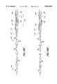
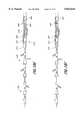
- FIGS. 18A-Hillustrate the use of the catheters of the present invention in an emboli containment treatment procedure.
- the present inventionprovides a system of improved irrigation and aspiration catheters and methods for treating stenosis or occlusions within blood vessels and emboli particle containment.
- the methods and apparatus of the present inventionare adapted for use in the treatment of a stenosis or an occlusion in a blood vessel in which the stenosis or occlusion has a length and a width or thickness which at least partially occludes the vessel's lumen.
- occlusionincludes both partial and complete occlusions, stenosis, emboli, thrombi, plaque and any other substance which at least partially occludes the vessel's lumen.
- a main catheter having an occlusion balloon on its distal endwas first inserted into a 4 mm ID flexible polymer tube.
- a guidewire having a 4 mm inflatable occlusion balloon at its distal endwas inserted through the main catheter and past the distal end of the main catheter so that a 100 mm chamber was created between the two balloons within the flexible tube.
- An irrigation catheterwas then positioned just proximal of the guidewire balloon.
- the main and guidewire balloonswere then inflated to isolate the chamber.
- a pumpwas connected to an irrigation port on the irrigation catheter using a stopcock, and a pressure gauge was connected inline with the pump output line.
- a 60 cc syringewas connected to an aspiration port on the main catheter to provide aspiration pressure or vacuum.
- a vacuum/pressure gaugewas connected inline with the aspiration line to the syringe.
- a 100 ml beaker of fluid(8.5 g/L sodium chloride solution or water) to be used in the test was then provided. The pump was activated until the chamber was filled with fluid and all the air was out of the irrigation and aspiration catheters.
- the pumpwas activated and adjusted to the desired pressure. Twenty-five cc of fluid was measured and placed into an empty beaker, and the input line to the pump was placed into the beaker. The stopcock to the aspiration catheter was closed, and the plunger on the 60 cc syringe was pulled back until the desired vacuum was obtained. The pump was then turned on, and simultaneously, the stopcock to the aspiration port was opened and a timer was started. When the desired time had passed, the pump was turned off and the fluid remaining in the beaker and the fluid collected in the 60 cc syringe was measured.
- the irrigation pressurewas varied between 5 and 30 psig with the aspiration pressure varying between -10 and -25 in-Hg.
- the resultsshow that there was little difference between the use of the saline solution and the use of water.
- the emboli containment system of the present inventioncomprises an inner catheter having an occlusive device at its distal end, a main catheter having an occlusive device at its distal end and an intermediate catheter. Separate irrigation and aspiration catheters can also be used if desired, either as a single catheter incorporating both or as two different devices.
- FIG. 3illustrates a side view of a catheter which can be used as the outer or main catheter of the present system.
- Catheter 110generally comprises an elongate flexible tubular body 116 extending between a proximal control end 112 and a distal functional end 114.
- the tubular body 116has a main lumen 130 which extends between the ends 112 and 114.
- the main lumen 130terminates in a proximal opening 123 and a distal opening 127.
- a smaller inflation lumen 132configured in a side-by-side relationship with the main lumen 130, extends along the length of the tubular body 116, and terminates within an occlusion balloon 126 mounted on the distal end 114 of the catheter 110, as described below.
- the inflation lumen 132is in fluid communication with the occlusion balloon 126, such that fluid passing through the inflation lumen 132 may be used to inflate or deflate the balloon 126.
- the proximal end of the inflation lumen 132can terminate at one of the ports 122, 124 on the proximal end of the catheter 110.
- a control manifold 119is provided at the proximal end 112 of the catheter 110.
- the control manifold 119is generally provided with a number of ports to provide access to the catheter lumen 130.
- the control manifold 119is provided with a catheter end-access port 122 and a catheter side-access port 124, to provide an introduction point for the insertion of other catheters into the lumen 130.
- Ports 122 and 124are preferably provided with standard Touhy Borst connectors, although other types of connectors may be used.
- An inflation port 118in fluid communication with the small inflation lumen 132, is further provided on the manifold 119 for attachment of devices to inflate or deflate the occlusion balloon 126.
- the manifold 119is also provided with an irrigation/aspiration port 120 which is in fluid communication with the lumen 130, for attachment of devices to provide irrigation fluid or aspiration pressure.
- Other embodiments of the main catheter 110may feature more or less ports, depending upon the number of lumen in the catheter and the desired functionalities of the catheter.
- the manifold 119is preferably formed out of hard polymers or metals, which possess the requisite structural integrity to provide a functional access port to the catheter lumen, such as for balloon inflation or delivery of irrigation fluid and/or aspiration pressure.
- the manifold 119is integrally formed out of polycarbonate.
- any suitable materialmay be used to form the manifold 119.
- an inflatable balloon 126is mounted on the distal end 114 of the catheter 110.
- the inflatable balloon 126will function as an occlusion balloon, to prevent blood and debris from passing through the blood vessel distal to the balloon 126.
- the inflatable balloon 126is preferably able to expand to fit a variety of different blood vessel diameters. Accordingly, it is preferred that the inflatable balloon 126 have a compliant expansion profile, tending to increase in radial diameter with increasing inflation pressure.
- the balloon 126may be made out of materials which impart such expansion characteristics, including elastomeric materials such as latex or irradiated polyethylene.
- the inflatable balloon 126is formed out of a material comprising a block copolymer of styrene-ethylene-butylene-styrene, sold under the trade name C-FLEX. Further details as to balloons of this type are disclosed in our copending application entitled “Pre-Stretched Catheter Balloon” Ser. No. 08/812,876, filed on the same date as the present application currently pending, the entirety of which is incorporated by reference.
- FIG. 6is a side view of an irrigation catheter 140 or aspiration catheter which may be utilized as the intermediate catheter in the present invention. It should be understood that when an irrigation catheter is used for the intermediate catheter, aspiration occurs through the outer pathway between the intermediate and main catheters, while irrigation occurs through the inner pathway. Similarly, when an aspiration catheter is used, aspiration occurs through the inner pathway while irrigation occurs through the outer pathway. Irrigation fluid is supplied under pressure at the proximal end of the catheter 142 and injected into the containment chamber through the side holes 146 and through the distal end of the catheter 144.
- aspiration pressurecan be provided at the proximal end of the catheter 142 and fluid and debris aspirated through the side holes 146 and through the distal end of the catheter 144.
- the catheter 140can be about 125 cm in length and constructed from a plastic material such as HYTREL tubing or high density polyethylene (HDPE) or PEBAX (Atochem, France).
- HDPEhigh density polyethylene
- PEBAXPEBAX
- the durometer of the tube 148 materialis reduced in the distal section to about 55 whereas that of the proximal section 142 is higher, such as about 80.
- Proximal valves and fittingswhich are well known in the art can be mounted on the irrigation catheter 140 of FIG. 6.
- FIGS. 7-10illustrate another type of irrigation or aspiration catheter 230 a single operator catheter, which can be used as the intermediate catheter of the present system.
- irrigation catheterirrigation is through the inner pathway and aspiration is through the outer pathway. If the catheter is used for aspiration, aspiration is through the inner pathway and irrigation is through the outer pathway.
- the catheter 230has an adaptor 232 on its proximal end.
- This single operator catheter 230further comprises a long tubular body 236 having a distal end 238.
- the distal tip 238can include a radiopaque marker to aid in locating the tip 238 during insertion into the patient, and is preferably soft to prevent damage to the patient's vasculature.
- an inner catheter lumen 240is attached.
- This lumen 240provides a separate lumen, apart from the main irrigation or aspiration lumen 242 of the catheter 230, for the insertion of the inner catheter, and has an inner diameter sized to received the inner catheter.
- the inner diameter of the lumenis about 0.016 in to about 0.020 in, and more preferably is about 0.019 in.
- This inner catheter or guidewire lumencan be as short as 5 cm, but can extend 30 cm or longer in a proximal direction.
- the proximal end of the inner catheteris inserted into the distal end of the inner catheter lumen 240, and the lumen 240 is slidably advanced over the inner catheter. Only a short segment of the single operator catheter 230 rides over the inner catheter, and the inner catheter remains in the lumen 240 and does not enter the main lumen 242 of the catheter 230.
- the inner catheter lumen 240is shown in FIG. 7 as being located only on the distal end 238 of the shaft of the catheter 236, the lumen 240 can also be made to extend the entire length of the shaft 236 if desired. In both embodiments, the main lumen 242 is advantageously left completely unobstructed to provide more efficient irrigation or aspiration.
- the inner catheter lumen 240can also include a slit 241 or weakened area in the outside wall of the lumen 240 along the entire length of the lumen 240 to facilitate faster and easier insertion and removal of the inner catheter through the side wall of the lumen 240.
- FIG. 10Ais a cross-sectional view of a single operator intermediate catheter 252 positioned within the main catheter 250.
- the separate lumen 254 adapted to receive the inner catheteris positioned adjacent the lumen of the intermediate catheter 252. It should be understood that this positioning will occur when any single operator intermediate catheter is used.
- FIG. 10Aillustrates schematically the inner (IP) and outer pathways (OP) for irrigation and aspiration which are formed by the catheter system of the present invention when a single operator intermediate catheter is used.
- the catheter 260includes an adaptor 262, preferably a female luer adaptor, at its proximal end.
- the catheter 260further includes an aspiration port 264 to which a source of negative pressure is attached.
- the aspiration catheterfurther comprises a long tubular body 266 having a distal end 268.
- the distal tip 268can include a radiopaque marker to aid in locating the tip 268 during insertion into the patient, and is preferably soft to prevent damage to the patient's vasculature.
- the aspiration catheteris preferably about 145 cm in length, although this length can be varied as desired.
- the catheter body 266is hollow, with an internal diameter sized to allow aspiration of emboli and debris.
- the inner diameterranged from about 0.020 in to about 0.050 in, and is preferably about 0.045 in.
- the proximal end of the inner catheter 270is inserted into the distal end of the aspiration catheter 268, and the aspiration catheter 260 is slidably advanced over the inner catheter 270, which is positioned inside the hollow lumen 272 of the aspiration catheter 260.
- the position of the inner catheter 270 relative to the body of the aspiration catheter 266is illustrated in FIG. 13, but of course, can vary.
- a very long inner catheter 270generally around 300 cm in length, is used to facilitate the insertion of the aspiration catheter 260.
- FIGS. 14-15illustrate another embodiment of an aspiration catheter 250, a single operator catheter, suitable for use as an intermediate catheter in the present invention.
- This catheter 280comprises an elongate shaft 282 with a lumen 284 for aspiration.
- a separate inner catheter lumen 286is positioned adjacent the main aspiration lumen 284. Again, this lumen 286 provides a separate lumen, apart from the main lumen 284 of the catheter 280, for the insertion of the inner catheter.
- This inner catheter or guidewire lumen 286can be as short as 5 cm, but can extend 30 cm or longer in a proximal direction.
- the proximal end of the inner catheteris inserted into the distal end of the inner catheter lumen 286, and the lumen 286 is slidably advanced over the inner catheter. Only a short segment of the single operator aspiration catheter 280 rides over the inner catheter, and the inner catheter remains in the lumen 286 and does not enter the aspiration lumen 284 of the catheter 280.
- the lumen 286can have a slit (not shown) or weakened area in a side wall to facilitate insertion and/or removal of the inner catheter through the side wall of the lumen.
- a rheolitic devicesuch as the ANGIOJET thrombectomy catheter available from Possis Medical Inc., Minneapolis Minn. can be used.
- This deviceacts as both a therapy catheter and an aspiration catheter. The device breaks up the thrombus or other occlusion and removes it. This eliminates the need to provide separate catheters for these functions.
- the term "aspiration catheter”includes rheolitic devices and any device which creates an area of fluid turbulence and uses negative pressure to aspirate fluid and debris, and includes devices which create a venturi effect within the vessel.
- a single catheter having two separate lumenscan be used to provide both irrigation and aspiration.
- the dual lumen cathetercan be configured to be over-the-wire, or of single operator design.
- one lumenextends past the distal end of the catheter so that the opening of one lumen is spaced some distance apart from the opening of the second lumen. Thus, irrigation occurs some distance away from aspiration.
- a combined aspiration/therapy cathetercan be used.
- an angioplasty ballooncan be attached to the distal end of an aspiration catheter.
- the aspiration cathetercan be designed to deploy a stent within the occluded vessel, or the catheter could include an atherectomy device on its distal end. The aspiration and therapy devices are therefore delivered into the blood vessel together.
- the inner catheter apparatus 310can generally be comprised of four communicating members including an elongated tubular member 314, a balloon member 316 and a core-wire member 320 and a coil member 322.
- the catheter apparatus 310is preferably provided with an outer coating of a lubricous material, such as Teflon.
- the body tubular member 314 of the catheter apparatus 310is in the form of hypotubing and is provided with proximal and distal ends 314A and 314B and as well as an inner lumen 315 extending along the tubular member 314.
- the balloon member 316is coaxially mounted on the distal end 314B of the tubular member 314 by suitable adhesives 319 at a proximal end 316A and a distal end 316B of the balloon member 316 as in the manner shown in FIG. 17.
- the core-wire member 320 of the catheter 310may be comprised of a flexible wire 320.
- the flexible wire 320is joined by soldering, crimping, or brazing at a proximal end 320A of the flexible wire 320 to the distal end 314B of the tubular member 314 as in the manner show in FIG. 17.
- the proximal end 320A of the flexible wire 320has a transverse cross sectional area substantially less than the smallest transverse cross-sectional area of the inner lumen 315 of the tubular member 314.
- the flexible wire 320tapers in the distal end 320B to smaller diameters to provide greater flexibility to the flexible wire 320.
- the flexible wiremay be in the form of a solid rod, ribbon or a helical coil or wire or combinations thereof.
- the distal end 320B of the flexible wire 320is secured to a rounded plug 318 of solder or braze at the distal end 322B of the coil member 322.
- the coil member 322 of the catheter 310may be comprised of a helical coil 322.
- the coil member 322is coaxially disposed about the flexible wire 320, and is secured to the flexible wire 320 by soldering or brazing at about the proximal end 320A of the flexible wire 320 as in the manner shown in FIG. 17.
- the balloon member 316is preferably a compliant balloon formed of a suitable elastic material such as a latex or the like.
- the flexible coil 322is preferably formed of a radiopaque material such as platinum or gold.
- the flexible core-wire 320 and the tubular member 314are preferably formed of a nickel-titanium alloy or stainless steel.
- the catheters of the present inventionare preferably provided with a coating on the outer surface, or on both the inner and outer surfaces.
- Suitable coatingsinclude hydrophilic, hydrophobic and antithrombogenic coatings. Examples include heparin and TEFLON. These coatings can be applied using methods well known in the art.
- FIGS. 18A-FThe operation and use of the emboli containment system utilizing the catheters of the present invention for treating occluded vessels will now be described in connection with an occlusion formed by a stenosis in a carotid artery, as illustrated in FIGS. 18A-F.
- proximalrefers to the portion of the catheter closest to the end which remains outside the patient's body, while “distal” refers to the portion closest to the end which is inserted into the body.
- a guiding catheter(not shown) is first introduced into the patient's vasculature through an incision in the femoral artery in the patient's groin.
- the guide catheteris advanced through the artery into the aorta of the heart of the patient and into the ostium of the carotid artery to be treated, where it remains throughout the procedure if needed.
- Fluoroscopyis typically used to guide the catheter and other devices to the desired location within the patient.
- the devicesare typically marked with radiopaque markings to facilitate visualization of the insertion and positioning of the devices.
- a main catheter 410 having a distal attached occlusive device 412in this example an inflatable balloon, is advanced into the ostium of the carotid artery and into the lumen 418 of the vessel 414.
- the main catheter 410 with the occlusive device 412 thereonis advanced until the device 412 is just proximal to the stenosis 406.
- the deviceis activated, i.e. the balloon 412 is then inflated, to occlude the vessel 414.
- the inner catheterin this example a guidewire 400, having an occlusive device 402, in this example an inflatable balloon, at its distal end 404 is next delivered through the main catheter 410.
- the occlusive device 402is positioned just distal to the occlusion 406.
- the occlusive deviceis activated, i.e., the balloon 402 is inflated to create an isolated chamber within the vessel which surrounds the occlusion.
- the balloons 402, 412are each progressively inflated until they engage the side wall of the vessel 414 to occlude the lumen 418.
- the distance between the proximal end of the occlusive device on the guidewire 404 and the distal tip of the occlusive device on the main catheter 416should be approximately 5-10 cm.
- the present inventionallows for the creation of a treatment and containment chamber whose length can be easily adjusted to isolate a specific area within a blood vessel.
- a working space 422is provided between the balloons 402, 412, so that therapeutic procedures can be undertaken to remove or reduce the occlusion 406 in the space between the balloons 422, without risk of unwanted particles or emboli escaping into the blood stream.
- the inner catheter 400 and the main catheter 410 with their attached distal occlusive devices 402, 412are therefore used to create a chamber 422 surrounding the occlusion 406, and act to contain the emboli and debris 424 resulting from the treatment of the occlusion 406 as illustrated in FIG. 18C.
- a third occlusive devicecan be delivered through the main catheter and deployed to occlude, for example, a branch or collateral vessel off the vessel being treated. This will ensure that the desired area within the vessel remains isolated during the treatment procedure.
- a guide catheter or angiography cathetercan first be delivered to the site of the occlusion.
- the inner catheteris inserted through the guide or angiography catheter, and positioned within the patient.
- the guide or angiography catheteris removed, and the main catheter is inserted over the inner catheter into position proximal to the occlusion.
- the occlusive device at the distal end of the main catheteris activated, the occlusive device on the inner catheter is put into position distal to the occlusion and activated, and the procedure continues as described above.
- the main cathetercan be delivered directly to a position just proximal to the occlusion, without use of a guide or angiography catheter.
- the inner catheteris then delivered through the main catheter as described above.
- the inner cathetercan be delivered first through the guide catheter.
- the occlusive device on the distal end of the inner catheteris positioned distal to the occlusion.
- the main catheteris introduced over the inner catheter and advanced into the ostium of the carotid artery and into the lumen of the vessel.
- the main catheteris advanced until the balloon is just proximal to the occlusion.
- the intermediate catheteris then delivered into the chamber to provide appropriate therapy.
- the occlusive devices on the distal ends of the inner and main cathetersare activated, to create a treatment and isolation chamber surrounding the occlusion. This method can be used when the physician determines that the risk of crossing the occlusion prior to activation of the proximal occlusive device is minimal.
- an intermediate catheter 420is delivered to the site of the occlusion 406.
- the intermediate catheter 420is a therapy catheter having an angioplasty balloon on its distal end.
- the intermediate catheter 420is delivered to the site of the occlusion 406 as shown in FIG. 18B.
- the term "therapy catheter”is meant to include any of a number of known devices used to treat an occluded vessel.
- a catheter carrying an inflatable or mechanically activated balloon for use in balloon angioplastycan be delivered to dilate the stenosis.
- Thermal balloon angioplastyincludes the use of heat to "mold" the vessel to the size and shape of the angioplasty balloon.
- an intravascular stentcan be delivered via a balloon catheter and deployed at the site of the stenosis to keep the vessel open.
- Cutting, shaving, scraping, or pulverizing devicescan be delivered to excise the stenosis in a procedure known as atherectomy.
- a laser or ultrasound devicecan also be delivered and used to ablate plaque within the vessel.
- Various types of rheolitic devicescould be used.
- Various thrombolytic or other types of drugscan be delivered locally in high concentrations to the site of the occlusion. It is also possible to deliver various chemical substances or enzymes via a catheter to the site of the stenosis to dissolve the obstruction.
- the cathetercan also include a therapeutic device, such as an angioplasty balloon, and be capable of providing irrigation or aspiration through its main lumen.
- the term "therapy catheter”encompasses these and other similar devices.
- a balloon angioplasty catheter 420is positioned such that the distal end with the balloon 426 thereon is at the site of the stenosis 406.
- the balloon 426is inflated with a suitable inflation medium, as for example a radiopaque liquid.
- the angioplasty balloon 426can be inflated to the desired pressure to cause compression of the plaque of the stenosis 406 against the sidewall of lumen 414 by the application of appropriate inflation pressure, as shown in FIG. 18D.
- the balloon 426can be formed of a non-elastic relatively non-compliant material so that appropriate pressures, such as 10-15 atmospheres, can be created within the balloon to apply compressive forces to the vessel 414 without danger of rupturing the vessel 414. It should be appreciated that the non-elastic capabilities can also be achieved by a composite elastic material.
- the therapy balloon 426is deflated as illustrated in FIG. 18E.
- a source of irrigation fluid(not shown) is connected to the adaptor 434 located at the proximal end of the therapy catheter 420, and a source of aspiration (not shown) is connected to an adaptor 436 located at the proximal end of the main catheter 410, as illustrated in FIG. 18F.
- the source of irrigation fluidis a bag of normal saline, typically used in intravenous infusion.
- the source of aspirationis preferably a syringe.
- Irrigation fluidis provided through the inner pathway between the therapy catheter 420 and the guidewire 400, while aspiration is provided through the outer pathway between the therapy catheter 420 and the main catheter 410 as shown by the small arrows in FIG. 18F.
- irrigation fluidcould be provided through the outer pathway while aspiration is provided through the inner pathway.
- suitable pressuresare provided to ensure that the change in pressure inside the chamber does not damage the vessel.
- the change in pressure as fluid flows into and out of the chambershould not exceed about 50 psi.
- Suitable negative pressuresrange from approximately -10 to -30 in-Hg for aspiration, and irrigation pressure is about 5 to 30 psig. Note that these pressures are measured at the proximal end of the catheters.
- the therapy catheteris removed from the emboli containment system, and an irrigation catheter is delivered to the emboli containment chamber.
- the irrigation catheteris inserted through the main catheter lumen.
- the main lumen of the irrigation cathetercan ride over the inner catheter, or the inner catheter can be positioned in a separate lumen adjacent to the main lumen.
- the distal end of the irrigation catheteris positioned just proximal the distal occlusion balloon, preferably approximately 2 cm from the balloon.
- the irrigation and main catheterare sized such that the irrigation catheter can pass through the main catheter lumen and the annulus or outer pathway between the main catheter lumen and the irrigation catheter is large enough to allow aspiration of the blood and debris within the chamber through it.
- Irrigation fluidis provided through the inner pathway between the inner catheter and the irrigation catheter.
- an aspiration catheter, or similar debris removing devicecan be used as the intermediate catheter.
- the aspiration catheteris delivered in the same manner as described above for the irrigation catheter. Aspiration then occurs through the inner pathway, while irrigation is provided through the outer pathway.
- irrigation and aspirationare performed.
- the irrigation fluid and aspirationare delivered in such a way as to ensure that the change of pressure within the chamber is below about 50 psi to avoid damaging the vessel.
- the irrigation fluidpreferably normal saline solution, is preferably delivered at a pressure of from about 5 psi to about 50 psi; 5 psi is preferred.
- the aspiration pressureis preferably between about -5 and -30 in-Hg, and more preferably is about -20 in-Hg.
- Flow rates inside the chamberare optimal at 30 psi irrigation pressure and -10 to -25 in-Hg aspiration pressure. Again, these pressures are measured from at the proximal end of the catheters.
- the irrigation and aspirationcan be delivered simultaneously, continuously, or delivery can be pulsed, or one can be delivered continuously while the other is delivered in a pulsed fashion. The user can determine the best method of delivery to provide optimized flow, turbulence, and clearance within the chamber.
- the inflation pressure within the distal occlusion balloon 402is maintained at a level greater than the pressure in the chamber and the jet created by irrigation to avoid the leakage of fluid and debris past the distal occlusion balloon 402.
- the inflation pressure in the proximal occlusion balloon 412should be maintained at a level greater than the pressure in the chamber and the aspiration pulsation to avoid having fluid aspirated from behind the balloon 412 and possibly aspirating the balloon 412 itself.
- the irrigation and aspiration pressures providedare such that the change in pressure during fluid flow into and out of the vessel does not damage the vessel.
- the change in pressureis preferably no greater than about 50 psi.
- the aspiration catheteris delivered such that its distal end is positioned approximately 1-2 cm from the distal occlusive device.
- the proximal occlusive deviceis then deactivated, to allow blood flow into the chamber.
- This blood flowis used as irrigation flow.
- the blood, acting as irrigation fluidis aspirated together with particles and debris through the aspiration catheter. This eliminates the need for a separate source of irrigation fluid.
- the blood flow rate in the vesselis greater than about 100 cc/min, and flow rates of 60-80 cc/min are preferred. This method is illustrated in FIG. 18G.
- the proximal occlusive deviceis deactivated, allowing blood flow into the chamber.
- the bloodacting as irrigation fluid, is aspirated together with particles and debris through the opening in the main catheter. This eliminates the need for a separate aspiration catheter and a separate source of irrigation fluid, thereby reducing the time necessary to complete the procedure.
Landscapes
- Health & Medical Sciences (AREA)
- Life Sciences & Earth Sciences (AREA)
- Heart & Thoracic Surgery (AREA)
- Engineering & Computer Science (AREA)
- Biomedical Technology (AREA)
- Veterinary Medicine (AREA)
- Public Health (AREA)
- General Health & Medical Sciences (AREA)
- Animal Behavior & Ethology (AREA)
- Hematology (AREA)
- Anesthesiology (AREA)
- Pulmonology (AREA)
- Biophysics (AREA)
- Child & Adolescent Psychology (AREA)
- Vascular Medicine (AREA)
- Surgery (AREA)
- Mechanical Engineering (AREA)
- Orthopedic Medicine & Surgery (AREA)
- Nuclear Medicine, Radiotherapy & Molecular Imaging (AREA)
- Medical Informatics (AREA)
- Molecular Biology (AREA)
- External Artificial Organs (AREA)
Abstract
Description
p.sub.1 +1/2ρV.sub.1.sup.2 +γZ.sub.1 =p.sub.2 +1/2ρV.sub.2.sup.2 +γZ.sub.2
Δp=KρV.sup.2 /2 .letKρ/2=k.sub.2
Δp=k.sub.2 V.sup.2
Δp∝V.sup.2
TABLE 1 ______________________________________ Test Apparatus Dimensional Breakdown Main Catheter ID/OD: .065/.086 Irrigation Catheter ID/OD: .038/.046 Asp. X-sectional Area: .0017 in.sup.2 Chamber length: 10 cm Chamber ID: .4 cm Chamber Volume: 1.3 cc ______________________________________
TABLE 2 ______________________________________ Factors and levels Factor Low Level High Level______________________________________ Irrigation Pressure 5 psig 30 psig Aspiration Pressure -10 in-Hg -25 in-Hg ______________________________________
TABLE 3 __________________________________________________________________________Flow Data Using a Saline Solution for Irrigation Initial* Irr Asp δVin δVout δVin-δVout Time ASP Flow Rate δP Initial Press Initial Press mean stdev mean stdev mean stdev mean stdev mean stdev (psi) (psig) (in-Hg, gauge) (cc) (cc) (cc) (cc) (cc) (cc) (sec) (sec) (cc/min) (cc/min) __________________________________________________________________________9.9 5 -10 4.2 .20 4.1 .23 .2 .12 53.7 1.46 4.6 .15 17.3 5 -25 8.3 .58 8.4 .35 -.1 .23 54.8 .37 9.2 .33 19.9 15 -10 9.1 .12 8.8 .20 .3 .31 53.2 1.04 9.9 .41 27.3 15 -25 10.5 .46 8.4 .53 2.1 .42 55.6 2.45 9.1 .65 34.9 30 -10 10.1 .12 9.3 9.27 .8 .40 53.7 .58 10.4 .36 42.3 30 -25 10.2 .40 9.1 .61 1.1 .23 53.6 .58 10.2 .57 __________________________________________________________________________
TABLE 4 __________________________________________________________________________Flow Data Using Water for Irrigation Initial* Irr Asp δVin δVout δVin-δVout Time ASP Flow Rate δP Initial Press Initial Press mean stdev mean stdev mean stdev mean stdev mean stdev (psi) (psig) (in-Hg, gauge) (cc) (cc) (cc) (cc) (cc) (cc) (sec) (sec) (cc/min) (cc/min) __________________________________________________________________________9.9 5 -10 7.3 .30 6.6 .38 .7 .15 57.7 2.23 6.9 .15 17.3 5 -25 14.4 2.09 13.4 1.43 1.0 2.15 56.1 .46 14.4 1.47 19.9 15 -10 12.1 4.22 9.3 .58 2.8 3.64 56.0 .57 10.0 .56 27.3 15 -25 10.5 .50 9.9 .61 .6 .53 54.6 2.81 10.9 .78 34.9 30 -10 10.9 1.01 10.1 .50 .7 .76 55.5 3.41 11.0 .15 42.3 30 -25 9.8 .35 10.0 .20 -2 .20 53.1 .99 11.3 .15 __________________________________________________________________________ *Pressure equalization after max 45 sec. As δP increases, the time to equalize increases δP is the pressure differential between the irrigation bag and the vacuum in the aspiration syringe V = volume and n = 3 unless otherwise noted
TABLE 5 ______________________________________ Data Analysis and Model for Flow Rate (solution: saline) ______________________________________ Adjusted R.sup.2 .994 Standard Error .227 Mean Abs. Error .1278 ______________________________________ Coefficient Error Factor* p-value ______________________________________ Flow Rate (cc/min)= 8.6 ±.0654 3.367 ±.1309 Irrigation .0000 -2.2 ±.1309 Aspiration .0000 2.37 ±.1309 Irr* Asp .0000 ______________________________________ *Use coded values between -1 an 1 to determine predicted flow rates
Claims (41)
Priority Applications (8)
| Application Number | Priority Date | Filing Date | Title |
|---|---|---|---|
| US08/812,875US5833644A (en) | 1996-05-20 | 1997-03-06 | Method for emboli containment |
| US09/026,013US6152909A (en) | 1996-05-20 | 1998-02-19 | Aspiration system and method |
| DE69834563TDE69834563T2 (en) | 1997-03-06 | 1998-03-06 | extraction system |
| AT98907741TATE326255T1 (en) | 1997-03-06 | 1998-03-06 | EXTRACTION SYSTEM |
| PCT/US1998/004494WO1998039047A1 (en) | 1997-03-06 | 1998-03-06 | Aspiration system and method |
| EP98907741AEP1011775B1 (en) | 1997-03-06 | 1998-03-06 | Aspiration system |
| AU63477/98AAU6347798A (en) | 1997-03-06 | 1998-03-06 | Aspiration system and method |
| US09/591,733US6398773B1 (en) | 1996-05-20 | 2000-06-12 | Aspiration system and method |
Applications Claiming Priority (2)
| Application Number | Priority Date | Filing Date | Title |
|---|---|---|---|
| US65046496A | 1996-05-20 | 1996-05-20 | |
| US08/812,875US5833644A (en) | 1996-05-20 | 1997-03-06 | Method for emboli containment |
Related Parent Applications (1)
| Application Number | Title | Priority Date | Filing Date |
|---|---|---|---|
| US65046496AContinuation-In-Part | 1994-07-19 | 1996-05-20 |
Related Child Applications (2)
| Application Number | Title | Priority Date | Filing Date |
|---|---|---|---|
| US81380797AContinuation-In-Part | 1996-05-20 | 1997-03-06 | |
| US09/026,013Continuation-In-PartUS6152909A (en) | 1996-05-20 | 1998-02-19 | Aspiration system and method |
Publications (1)
| Publication Number | Publication Date |
|---|---|
| US5833644Atrue US5833644A (en) | 1998-11-10 |
Family
ID=46203078
Family Applications (1)
| Application Number | Title | Priority Date | Filing Date |
|---|---|---|---|
| US08/812,875Expired - LifetimeUS5833644A (en) | 1996-05-20 | 1997-03-06 | Method for emboli containment |
Country Status (1)
| Country | Link |
|---|---|
| US (1) | US5833644A (en) |
Cited By (227)
| Publication number | Priority date | Publication date | Assignee | Title |
|---|---|---|---|---|
| US6066158A (en)* | 1996-07-25 | 2000-05-23 | Target Therapeutics, Inc. | Mechanical clot encasing and removal wire |
| US6066149A (en)* | 1997-09-30 | 2000-05-23 | Target Therapeutics, Inc. | Mechanical clot treatment device with distal filter |
| US6129739A (en)* | 1999-07-30 | 2000-10-10 | Incept Llc | Vascular device having one or more articulation regions and methods of use |
| US6159197A (en)* | 1999-09-17 | 2000-12-12 | Richard R. Heuser | Method and apparatus for treating body tissues and bodily fluid vessels |
| US6159195A (en)* | 1998-02-19 | 2000-12-12 | Percusurge, Inc. | Exchange catheter and method of use |
| US6165196A (en)* | 1997-09-26 | 2000-12-26 | Corvascular Surgical Systems, Inc. | Perfusion-occlusion apparatus |
| US6179861B1 (en) | 1999-07-30 | 2001-01-30 | Incept Llc | Vascular device having one or more articulation regions and methods of use |
| US6179859B1 (en) | 1999-07-16 | 2001-01-30 | Baff Llc | Emboli filtration system and methods of use |
| US6203561B1 (en) | 1999-07-30 | 2001-03-20 | Incept Llc | Integrated vascular device having thrombectomy element and vascular filter and methods of use |
| WO2001019445A1 (en)* | 1999-09-17 | 2001-03-22 | Advanced Cardiovascular Systems, Inc. | Balloon catheter to deliver a drug or to remove substances such as emboli or excess drug |
| US6214026B1 (en) | 1999-07-30 | 2001-04-10 | Incept Llc | Delivery system for a vascular device with articulation region |
| US6245012B1 (en) | 1999-03-19 | 2001-06-12 | Nmt Medical, Inc. | Free standing filter |
| WO2001045572A1 (en)* | 1999-12-22 | 2001-06-28 | Boston Scientific Limited | Endoluminal occlusion-irrigation catheter and methods of use |
| US6270477B1 (en)* | 1996-05-20 | 2001-08-07 | Percusurge, Inc. | Catheter for emboli containment |
| US20020010488A1 (en)* | 2000-06-16 | 2002-01-24 | Crawford Lynn D. | Balloon occlusion device having a proximal valve |
| US20020016564A1 (en)* | 2000-05-31 | 2002-02-07 | Courtney Brian K. | Embolization protection sytem for vascular procedures |
| US6364900B1 (en)* | 1999-07-14 | 2002-04-02 | Richard R. Heuser | Embolism prevention device |
| US6371969B1 (en) | 1997-05-08 | 2002-04-16 | Scimed Life Systems, Inc. | Distal protection device and method |
| US6371971B1 (en) | 1999-11-15 | 2002-04-16 | Scimed Life Systems, Inc. | Guidewire filter and methods of use |
| US6371970B1 (en) | 1999-07-30 | 2002-04-16 | Incept Llc | Vascular filter having articulation region and methods of use in the ascending aorta |
| US6398773B1 (en) | 1996-05-20 | 2002-06-04 | Medtronic Percusurge, Inc | Aspiration system and method |
| US6443926B1 (en) | 2000-02-01 | 2002-09-03 | Harold D. Kletschka | Embolic protection device having expandable trap |
| US6454741B1 (en) | 1997-03-06 | 2002-09-24 | Medtronic Percusurge, Inc. | Aspiration method |
| US6468291B2 (en) | 1999-07-16 | 2002-10-22 | Baff Llc | Emboli filtration system having integral strut arrangement and methods of use |
| US6475185B1 (en) | 2000-02-24 | 2002-11-05 | Scimed Life Systems, Inc. | Occlusion device |
| US20020173817A1 (en)* | 2000-02-01 | 2002-11-21 | Kletschka Harold D. | Angioplasty device and method of making the same |
| US6485502B2 (en) | 2000-03-10 | 2002-11-26 | T. Anthony Don Michael | Vascular embolism prevention device employing filters |
| US6485500B1 (en) | 2000-03-21 | 2002-11-26 | Advanced Cardiovascular Systems, Inc. | Emboli protection system |
| WO2002094111A2 (en) | 2001-01-16 | 2002-11-28 | Incept Llc | Vascular device for emboli and thrombi removal |
| US20030009190A1 (en)* | 2000-02-01 | 2003-01-09 | Kletschka Harold D. | Angioplasty device and method of making same |
| US6508782B1 (en) | 1992-05-19 | 2003-01-21 | Bacchus Vascular, Inc. | Thrombolysis device |
| US6527791B2 (en) | 1999-10-25 | 2003-03-04 | John S. Fisher | Emboli capturing device |
| US20030055398A1 (en)* | 1997-03-06 | 2003-03-20 | Imran Mir A. | Methods for reducing distal embolization |
| US6537295B2 (en) | 2001-03-06 | 2003-03-25 | Scimed Life Systems, Inc. | Wire and lock mechanism |
| US6544279B1 (en) | 2000-08-09 | 2003-04-08 | Incept, Llc | Vascular device for emboli, thrombus and foreign body removal and methods of use |
| US6544280B1 (en) | 1999-02-24 | 2003-04-08 | Scimed Life Systems, Inc. | Intravascular filter and method |
| US6544276B1 (en) | 1996-05-20 | 2003-04-08 | Medtronic Ave. Inc. | Exchange method for emboli containment |
| US20030088194A1 (en)* | 2001-11-06 | 2003-05-08 | Bonnette Michael J. | Gas Inflation/evacution system for guidewire having occlusive device |
| US6569148B2 (en) | 1996-05-20 | 2003-05-27 | Medtronic Ave, Inc. | Methods for emboli containment |
| US6589263B1 (en) | 1999-07-30 | 2003-07-08 | Incept Llc | Vascular device having one or more articulation regions and methods of use |
| US6605074B2 (en) | 1999-03-16 | 2003-08-12 | Medtronic Ave, Inc. | Method for containing and removing occlusions in the carotid arteries |
| US20030150821A1 (en)* | 1999-07-16 | 2003-08-14 | Bates Mark C. | Emboli filtration system and methods of use |
| US20030153943A1 (en)* | 2001-03-12 | 2003-08-14 | Michael T. Anthony Don | Vascular filter with improved strength and flexibility |
| US6616681B2 (en) | 2000-10-05 | 2003-09-09 | Scimed Life Systems, Inc. | Filter delivery and retrieval device |
| US6620182B1 (en) | 1999-07-30 | 2003-09-16 | Incept Llc | Vascular filter having articulation region and methods of use in the ascending aorta |
| US6620148B1 (en) | 1999-08-04 | 2003-09-16 | Scimed Life Systems, Inc. | Filter flush system and methods of use |
| US6635070B2 (en) | 2001-05-21 | 2003-10-21 | Bacchus Vascular, Inc. | Apparatus and methods for capturing particulate material within blood vessels |
| US6652505B1 (en) | 1999-08-03 | 2003-11-25 | Scimed Life Systems Inc. | Guided filter with support wire and methods of use |
| US6663651B2 (en) | 2001-01-16 | 2003-12-16 | Incept Llc | Systems and methods for vascular filter retrieval |
| US6663652B2 (en) | 1997-03-06 | 2003-12-16 | John M. K. Daniel | Distal protection device and method |
| US6673090B2 (en) | 1999-08-04 | 2004-01-06 | Scimed Life Systems, Inc. | Percutaneous catheter and guidewire for filtering during ablation of myocardial or vascular tissue |
| US6676682B1 (en) | 1997-05-08 | 2004-01-13 | Scimed Life Systems, Inc. | Percutaneous catheter and guidewire having filter and medical device deployment capabilities |
| US20040010280A1 (en)* | 2002-07-12 | 2004-01-15 | Adams Daniel O. | Device to create proximal stasis |
| US6689151B2 (en) | 2001-01-25 | 2004-02-10 | Scimed Life Systems, Inc. | Variable wall thickness for delivery sheath housing |
| US6726703B2 (en) | 2000-11-27 | 2004-04-27 | Scimed Life Systems, Inc. | Distal protection device and method |
| EP1204379A4 (en)* | 1999-06-21 | 2004-05-12 | Lawrence O'connor | Angioplasty catheter with transducer using balloon for focusing of ultrasonic energy |
| US6755847B2 (en) | 2001-10-05 | 2004-06-29 | Scimed Life Systems, Inc. | Emboli capturing device and method of manufacture therefor |
| US6793666B2 (en) | 2001-12-18 | 2004-09-21 | Scimed Life Systems, Inc. | Distal protection mechanically attached filter cartridge |
| US20040193046A1 (en)* | 2003-03-28 | 2004-09-30 | John E. Nash | Catheter with associated extension lumen |
| US20040193099A1 (en)* | 2001-07-17 | 2004-09-30 | Macmahon John M. | Fluid exchange system for controlled and localized irrigation and aspiration |
| US6814740B2 (en) | 1999-10-27 | 2004-11-09 | Scimed Life Systems, Inc. | Retrieval device made of precursor alloy cable |
| US20040243175A1 (en)* | 2001-03-12 | 2004-12-02 | Don Michael T. Anthony | Vascular obstruction removal system and method |
| US20050004517A1 (en)* | 2000-06-02 | 2005-01-06 | Courtney Brian K. | Embolization protection system for vascular procedures |
| US6840950B2 (en) | 2001-02-20 | 2005-01-11 | Scimed Life Systems, Inc. | Low profile emboli capture device |
| US6849068B1 (en)* | 1997-03-06 | 2005-02-01 | Medtronic Ave, Inc. | Aspiration catheter |
| US6878291B2 (en) | 2003-02-24 | 2005-04-12 | Scimed Life Systems, Inc. | Flexible tube for cartridge filter |
| US6887257B2 (en) | 2001-10-19 | 2005-05-03 | Incept Llc | Vascular embolic filter exchange devices and methods of use thereof |
| US6902572B2 (en) | 2003-04-02 | 2005-06-07 | Scimed Life Systems, Inc. | Anchoring mechanisms for intravascular devices |
| US20050131447A1 (en)* | 2001-05-01 | 2005-06-16 | Wahr Dennis W. | Emboli protection devices and related methods of use |
| US6926729B1 (en) | 1996-01-31 | 2005-08-09 | Scimed Life Systems, Inc. | Low profile valve and method of making |
| US6926725B2 (en) | 2002-04-04 | 2005-08-09 | Rex Medical, L.P. | Thrombectomy device with multi-layered rotational wire |
| US20050177185A1 (en)* | 2004-02-05 | 2005-08-11 | Scimed Life Systems, Inc. | Counterwound coil for embolic protection sheath |
| US20050182437A1 (en)* | 2001-11-06 | 2005-08-18 | Bonnette Michael J. | Guidewire assembly including a repeatably inflatable occlusive balloon on a guidewire ensheathed with a spiral coil |
| US6932828B2 (en) | 2001-11-06 | 2005-08-23 | Possis Medical, Inc. | Guidewire occlusion system utilizing repeatably inflatable gas-filled occlusive device |
| US6932830B2 (en) | 2002-01-10 | 2005-08-23 | Scimed Life Systems, Inc. | Disc shaped filter |
| US6936025B1 (en) | 1992-05-19 | 2005-08-30 | Bacchus Vascular, Inc. | Thrombolysis device |
| US6936059B2 (en) | 2001-01-16 | 2005-08-30 | Scimed Life Systems, Inc. | Endovascular guidewire filter and methods of use |
| US6939361B1 (en) | 1999-09-22 | 2005-09-06 | Nmt Medical, Inc. | Guidewire for a free standing intervascular device having an integral stop mechanism |
| US20050209559A1 (en)* | 2004-03-19 | 2005-09-22 | Medtronic Vascular, Inc. A Delaware Corporation | Apparatus and methods for the treatment of chronic total occlusions |
| US6951570B2 (en) | 2001-07-02 | 2005-10-04 | Rubicon Medical, Inc. | Methods, systems, and devices for deploying a filter from a filter device |
| US6958059B2 (en) | 1996-05-20 | 2005-10-25 | Medtronic Ave, Inc. | Methods and apparatuses for drug delivery to an intravascular occlusion |
| US20050240165A1 (en)* | 2002-08-01 | 2005-10-27 | Shogo Miki | Suction catheter |
| US6960370B2 (en) | 2003-03-27 | 2005-11-01 | Scimed Life Systems, Inc. | Methods of forming medical devices |
| US20050245894A1 (en)* | 1996-05-20 | 2005-11-03 | Medtronic Vascular, Inc. | Methods and apparatuses for drug delivery to an intravascular occlusion |
| US6962598B2 (en) | 2001-07-02 | 2005-11-08 | Rubicon Medical, Inc. | Methods, systems, and devices for providing embolic protection |
| US6969396B2 (en) | 2003-05-07 | 2005-11-29 | Scimed Life Systems, Inc. | Filter membrane with increased surface area |
| US6974469B2 (en) | 1997-03-06 | 2005-12-13 | Scimed Life Systems, Inc. | Distal protection device and method |
| US20060025805A1 (en)* | 2001-02-28 | 2006-02-02 | Dobrava Eric M | Filter retrieval catheter |
| US6997939B2 (en) | 2001-07-02 | 2006-02-14 | Rubicon Medical, Inc. | Methods, systems, and devices for deploying an embolic protection filter |
| US6997938B2 (en) | 2002-02-12 | 2006-02-14 | Scimed Life Systems, Inc. | Embolic protection device |
| US7001406B2 (en) | 2002-05-23 | 2006-02-21 | Scimed Life Systems Inc. | Cartridge embolic protection filter and methods of use |
| US7029440B2 (en) | 2002-03-13 | 2006-04-18 | Scimed Life Systems, Inc. | Distal protection filter and method of manufacture |
| US7037316B2 (en) | 1997-07-24 | 2006-05-02 | Mcguckin Jr James F | Rotational thrombectomy device |
| US7052500B2 (en) | 2001-10-19 | 2006-05-30 | Scimed Life Systems, Inc. | Embolus extractor |
| US7060082B2 (en) | 2002-05-06 | 2006-06-13 | Scimed Life Systems, Inc. | Perfusion guidewire in combination with a distal filter |
| US7063707B2 (en) | 2002-03-06 | 2006-06-20 | Scimed Life Systems, Inc. | Medical retrieval device |
| US7077860B2 (en) | 1997-04-24 | 2006-07-18 | Advanced Cardiovascular Systems, Inc. | Method of reducing or eliminating thrombus formation |
| US7094249B1 (en) | 1997-03-06 | 2006-08-22 | Boston Scientific Scimed, Inc. | Distal protection device and method |
| US7115138B2 (en) | 2002-09-04 | 2006-10-03 | Boston Scientific Scimed, Inc. | Sheath tip |
| US7118539B2 (en) | 2002-02-26 | 2006-10-10 | Scimed Life Systems, Inc. | Articulating guide wire for embolic protection and methods of use |
| US20060229638A1 (en)* | 2005-03-29 | 2006-10-12 | Abrams Robert M | Articulating retrieval device |
| US20060253145A1 (en)* | 2005-05-05 | 2006-11-09 | Lucas Paul R | Multi-functional thrombectomy device |
| US7137991B2 (en) | 2003-02-24 | 2006-11-21 | Scimed Life Systems, Inc. | Multi-wire embolic protection filtering device |
| US7153320B2 (en) | 2001-12-13 | 2006-12-26 | Scimed Life Systems, Inc. | Hydraulic controlled retractable tip filter retrieval catheter |
| US7163550B2 (en) | 2003-03-26 | 2007-01-16 | Scimed Life Systems, Inc. | Method for manufacturing medical devices from linear elastic materials while maintaining linear elastic properties |
| US7163549B2 (en) | 2003-02-11 | 2007-01-16 | Boston Scientific Scimed Inc. | Filter membrane manufacturing method |
| US7169165B2 (en) | 2001-01-16 | 2007-01-30 | Boston Scientific Scimed, Inc. | Rapid exchange sheath for deployment of medical devices and methods of use |
| US7169161B2 (en) | 2001-11-06 | 2007-01-30 | Possis Medical, Inc. | Guidewire having occlusive device and repeatably crimpable proximal end |
| US7174636B2 (en) | 2002-09-04 | 2007-02-13 | Scimed Life Systems, Inc. | Method of making an embolic filter |
| US7198675B2 (en) | 2003-09-30 | 2007-04-03 | Advanced Cardiovascular Systems | Stent mandrel fixture and method for selectively coating surfaces of a stent |
| US20070083161A1 (en)* | 1997-01-09 | 2007-04-12 | Medtronic, Inc. | Oval-Shaped Cardiac Cannula |
| US7204464B2 (en) | 2005-01-21 | 2007-04-17 | Boston Scientific Scimed, Inc. | Medical wire holder |
| US20070106211A1 (en)* | 2005-10-26 | 2007-05-10 | Medtronic Vascular, Inc. | Catheter having oval aspiration lumen and method of making |
| US7226464B2 (en) | 2001-03-01 | 2007-06-05 | Scimed Life Systems, Inc. | Intravascular filter retrieval device having an actuatable dilator tip |
| US20070191812A1 (en)* | 2003-11-07 | 2007-08-16 | Takuji Nishide | Aspiration catheter |
| US7258891B2 (en) | 2001-06-28 | 2007-08-21 | Advanced Cardiovascular Systems, Inc. | Stent mounting assembly and a method of using the same to coat a stent |
| US20070214730A1 (en)* | 2006-03-17 | 2007-09-20 | Cota Thomas F | Gutter cover |
| US7297159B2 (en) | 2000-10-26 | 2007-11-20 | Advanced Cardiovascular Systems, Inc. | Selective coating of medical devices |
| US7300459B2 (en) | 2002-10-17 | 2007-11-27 | Heuser Richard R | Stent with covering and differential dilation |
| US7306618B2 (en) | 1999-07-30 | 2007-12-11 | Incept Llc | Vascular device for emboli and thrombi removal and methods of use |
| US7320697B2 (en) | 1999-07-30 | 2008-01-22 | Boston Scientific Scimed, Inc. | One piece loop and coil |
| US7326224B2 (en) | 2002-06-11 | 2008-02-05 | Boston Scientific Scimed, Inc. | Shaft and wire lock |
| US7374567B2 (en) | 2006-01-25 | 2008-05-20 | Heuser Richard R | Catheter system for connecting adjacent blood vessels |
| US7374560B2 (en) | 2001-05-01 | 2008-05-20 | St. Jude Medical, Cardiology Division, Inc. | Emboli protection devices and related methods of use |
| US20080140003A1 (en)* | 2006-12-06 | 2008-06-12 | Advanced Cardiovascular Systems, Inc. | Balloon catheter having a regrooming sheath and method for collapsing an expanded medical device |
| US7402141B2 (en) | 2003-08-27 | 2008-07-22 | Heuser Richard R | Catheter guidewire system using concentric wires |
| US20080312671A1 (en)* | 2007-06-12 | 2008-12-18 | Possis Medical, Inc. | Infusion flow guidewire system |
| US7473265B2 (en) | 2004-03-15 | 2009-01-06 | Boston Scientific Scimed, Inc. | Filter media and methods of manufacture |
| US7476236B2 (en) | 2001-03-01 | 2009-01-13 | Boston Scientific Scimed, Inc. | Embolic protection filter delivery sheath |
| US7478465B1 (en) | 2005-01-10 | 2009-01-20 | Boston Scientific Scimed, Inc. | Method of securing a restraining member on a medical device |
| US7481823B2 (en) | 2002-10-25 | 2009-01-27 | Boston Scientific Scimed, Inc. | Multiple membrane embolic protection filter |
| US7494468B2 (en) | 1999-10-05 | 2009-02-24 | Omnisonics Medical Technologies, Inc. | Ultrasonic medical device operating in a transverse mode |
| US7503895B2 (en) | 1999-10-05 | 2009-03-17 | Omnisonics Medical Technologies, Inc. | Ultrasonic device for tissue ablation and sheath for use therewith |
| US7513903B1 (en)* | 2004-05-08 | 2009-04-07 | Iris Ginron Zhao | Organ culture in situ |
| US20090093791A1 (en)* | 1999-09-17 | 2009-04-09 | Heuser Richard R | Devices and methods for treating chronic total occlusion |
| US7517352B2 (en) | 2000-04-07 | 2009-04-14 | Bacchus Vascular, Inc. | Devices for percutaneous remote endarterectomy |
| US7537600B2 (en) | 2003-06-12 | 2009-05-26 | Boston Scientific Scimed, Inc. | Valved embolic protection filter |
| US7553377B1 (en) | 2004-04-27 | 2009-06-30 | Advanced Cardiovascular Systems, Inc. | Apparatus and method for electrostatic coating of an abluminal stent surface |
| US7563324B1 (en) | 2003-12-29 | 2009-07-21 | Advanced Cardiovascular Systems Inc. | System and method for coating an implantable medical device |
| US7585309B2 (en) | 2002-05-16 | 2009-09-08 | Boston Scientific Scimed, Inc. | Aortic filter |
| US7594926B2 (en) | 2001-11-09 | 2009-09-29 | Boston Scientific Scimed, Inc. | Methods, systems and devices for delivering stents |
| US7604612B2 (en) | 2001-05-01 | 2009-10-20 | St. Jude Medical, Cardiology Division, Inc. | Emboli protection devices and related methods of use |
| US7615031B2 (en) | 2005-09-01 | 2009-11-10 | Medrad, Inc. | Gas inflation/evacuation system incorporating a multiple element valved guidewire assembly having an occlusive device |
| US7621904B2 (en) | 2004-10-21 | 2009-11-24 | Boston Scientific Scimed, Inc. | Catheter with a pre-shaped distal tip |
| US7625389B2 (en) | 2002-12-30 | 2009-12-01 | Boston Scientific Scimed, Inc. | Embolic protection device |
| US7632307B2 (en) | 2004-12-16 | 2009-12-15 | Advanced Cardiovascular Systems, Inc. | Abluminal, multilayer coating constructs for drug-delivery stents |
| US7645261B2 (en) | 1999-10-22 | 2010-01-12 | Rex Medical, L.P | Double balloon thrombectomy catheter |
| US7648727B2 (en) | 2004-08-26 | 2010-01-19 | Advanced Cardiovascular Systems, Inc. | Methods for manufacturing a coated stent-balloon assembly |
| US7651514B2 (en) | 2003-12-11 | 2010-01-26 | Boston Scientific Scimed, Inc. | Nose rider improvement for filter exchange and methods of use |
| US7695465B2 (en) | 2001-07-30 | 2010-04-13 | Boston Scientific Scimed, Inc. | Chronic total occlusion device with variable stiffness shaft |
| US7708770B2 (en) | 2001-11-09 | 2010-05-04 | Boston Scientific Scimed, Inc. | Stent delivery device with embolic protection |
| US20100121270A1 (en)* | 2008-11-12 | 2010-05-13 | Gunday Erhan H | Resector Balloon System |
| US7740644B2 (en) | 2003-02-24 | 2010-06-22 | Boston Scientific Scimed, Inc. | Embolic protection filtering device that can be adapted to be advanced over a guidewire |
| US7780611B2 (en) | 2003-05-01 | 2010-08-24 | Boston Scientific Scimed, Inc. | Medical instrument with controlled torque transmission |
| US7794414B2 (en) | 2004-02-09 | 2010-09-14 | Emigrant Bank, N.A. | Apparatus and method for an ultrasonic medical device operating in torsional and transverse modes |
| US7794472B2 (en) | 2004-08-11 | 2010-09-14 | Boston Scientific Scimed, Inc. | Single wire intravascular filter |
| US7837703B2 (en) | 2007-10-29 | 2010-11-23 | Salviac Limited | Guidewire for embolic device |
| EP2260898A1 (en)* | 2009-06-10 | 2010-12-15 | Ulrich Schäfer | Guide wire and method for its use |
| US7867547B2 (en) | 2005-12-19 | 2011-01-11 | Advanced Cardiovascular Systems, Inc. | Selectively coating luminal surfaces of stents |
| US7914492B2 (en) | 2003-01-27 | 2011-03-29 | Heuser Richard R | Catheter introducer system |
| US7959584B2 (en) | 2002-05-29 | 2011-06-14 | Boston Scientific Scimed, Inc. | Dedicated distal protection guidewires |
| US20110152683A1 (en)* | 2011-03-01 | 2011-06-23 | Gerrans Lawrence J | Abrading Balloon Catheter for Extravasated Drug Delivery |
| US7976527B2 (en) | 1997-10-17 | 2011-07-12 | Micro Therapeutics, Inc. | Device and method for controlling injection of liquid embolic composition |
| US7993329B2 (en) | 2002-08-13 | 2011-08-09 | Cook Medical Technologies Llc | ERCP catheter with a removable handle for lithotriptor compatible basket |
| US7998163B2 (en) | 2002-10-03 | 2011-08-16 | Boston Scientific Scimed, Inc. | Expandable retrieval device |
| US8003156B2 (en) | 2006-05-04 | 2011-08-23 | Advanced Cardiovascular Systems, Inc. | Rotatable support elements for stents |
| US20110218494A1 (en)* | 2008-11-12 | 2011-09-08 | Gerrans Lawrence J | Multi-Balloon Catheter for Extravasated Drug Delivery |
| US8017237B2 (en) | 2006-06-23 | 2011-09-13 | Abbott Cardiovascular Systems, Inc. | Nanoshells on polymers |
| US8038696B2 (en) | 2004-12-06 | 2011-10-18 | Boston Scientific Scimed, Inc. | Sheath for use with an embolic protection filter |
| US8048448B2 (en) | 2006-06-15 | 2011-11-01 | Abbott Cardiovascular Systems Inc. | Nanoshells for drug delivery |
| US8048441B2 (en) | 2007-06-25 | 2011-11-01 | Abbott Cardiovascular Systems, Inc. | Nanobead releasing medical devices |
| US8062321B2 (en) | 2006-01-25 | 2011-11-22 | Pq Bypass, Inc. | Catheter system for connecting adjacent blood vessels |
| US8070769B2 (en) | 2002-05-06 | 2011-12-06 | Boston Scientific Scimed, Inc. | Inverted embolic protection filter |
| US8123777B2 (en) | 2001-07-24 | 2012-02-28 | Incept, Llc | Apparatus and methods for aspirating emboli |
| US8157766B2 (en) | 2005-09-01 | 2012-04-17 | Medrad, Inc. | Torqueable kink-resistant guidewire |
| US20120179111A1 (en)* | 2011-01-06 | 2012-07-12 | Control Medical Technology, Llc | Elongate medical instruments with removable core guide wire extenders, guide wire extenders, systems and methods |
| US20120179140A1 (en)* | 2011-01-06 | 2012-07-12 | Fojtik Shawn P | Elongate medical instruments with removable core guide wire extenders, guide wire extenders, systems and methods |
| US8221348B2 (en) | 2005-07-07 | 2012-07-17 | St. Jude Medical, Cardiology Division, Inc. | Embolic protection device and methods of use |
| US8241315B2 (en) | 2004-06-24 | 2012-08-14 | Boston Scientific Scimed, Inc. | Apparatus and method for treating occluded vasculature |
| US8337519B2 (en) | 2003-07-10 | 2012-12-25 | Boston Scientific Scimed, Inc. | Embolic protection filtering device |
| US8348890B2 (en) | 2011-03-01 | 2013-01-08 | Sanovas, Inc. | Nested balloon catheter for localized drug delivery |
| US20130066348A1 (en)* | 2006-02-01 | 2013-03-14 | The Cleveland Clinic Foundation | Method and apparatus for increasing blood flow through an obstructed blood vessel |
| US8414543B2 (en) | 1999-10-22 | 2013-04-09 | Rex Medical, L.P. | Rotational thrombectomy wire with blocking device |
| US8444669B2 (en) | 2008-12-15 | 2013-05-21 | Boston Scientific Scimed, Inc. | Embolic filter delivery system and method |
| US8468678B2 (en) | 2002-10-02 | 2013-06-25 | Boston Scientific Scimed, Inc. | Expandable retrieval device |
| US8480629B2 (en) | 2005-01-28 | 2013-07-09 | Boston Scientific Scimed, Inc. | Universal utility board for use with medical devices and methods of use |
| US20130226146A1 (en)* | 2012-02-24 | 2013-08-29 | Kurt Tekulve | Clot removal system and method |
| US8535344B2 (en) | 2003-09-12 | 2013-09-17 | Rubicon Medical, Inc. | Methods, systems, and devices for providing embolic protection and removing embolic material |
| US8545418B2 (en) | 2004-08-25 | 2013-10-01 | Richard R. Heuser | Systems and methods for ablation of occlusions within blood vessels |
| US8603530B2 (en) | 2006-06-14 | 2013-12-10 | Abbott Cardiovascular Systems Inc. | Nanoshell therapy |
| US8647359B2 (en) | 2002-01-10 | 2014-02-11 | Boston Scientific Scimed, Inc. | Distal protection filter |
| US8790359B2 (en) | 1999-10-05 | 2014-07-29 | Cybersonics, Inc. | Medical systems and related methods |
| US8821476B2 (en) | 2009-12-02 | 2014-09-02 | Renovorx, Inc. | Devices, methods and kits for delivery of therapeutic materials to a pancreas |
| US8821478B2 (en) | 2011-03-04 | 2014-09-02 | Boston Scientific Scimed, Inc. | Catheter with variable stiffness |
| EP2789362A1 (en)* | 2007-11-21 | 2014-10-15 | Invatec S.p.A. | Balloon for the treatment of stenosis |
| US20150080853A1 (en)* | 2006-01-09 | 2015-03-19 | Smalling Medical Ventures, Llc | Aspiration Thrombectomy Catheter System, And Associated Methods |
| US9232948B2 (en) | 2003-12-23 | 2016-01-12 | Stryker Corporation | Catheter with distal occlusion apparatus |
| US9238119B2 (en) | 2010-08-12 | 2016-01-19 | Boston Scientific Limited | Infusion flow system and fluid coupling |
| US9301829B2 (en) | 2003-07-30 | 2016-04-05 | Boston Scientific Scimed, Inc. | Embolic protection aspirator |
| US9332998B2 (en) | 2012-08-13 | 2016-05-10 | Covidien Lp | Apparatus and methods for clot disruption and evacuation |
| US9332999B2 (en) | 2012-08-13 | 2016-05-10 | Covidien Lp | Apparatus and methods for clot disruption and evacuation |
| US9457171B2 (en) | 2009-12-02 | 2016-10-04 | Renovorx, Inc. | Devices, methods and kits for delivery of therapeutic materials to a target artery |
| US9468739B2 (en) | 2008-08-19 | 2016-10-18 | Covidien Lp | Detachable tip microcatheter |
| US10099040B2 (en) | 2013-06-03 | 2018-10-16 | Renovorx, Inc. | Occlusion catheter system and methods of use |
| US10124087B2 (en) | 2012-06-19 | 2018-11-13 | Covidien Lp | Detachable coupling for catheter |
| US20180353728A1 (en)* | 2013-03-15 | 2018-12-13 | Qx Medical, Llc | Boosting Catheter and Related Systems and Methods |
| US10512761B2 (en) | 2009-12-02 | 2019-12-24 | Renovorx, Inc. | Methods for delivery of therapeutic materials to treat pancreatic cancer |
| US10695543B2 (en) | 2017-05-18 | 2020-06-30 | Renovorx, Inc. | Methods for treating cancerous tumors |
| US10864323B2 (en) | 2011-03-01 | 2020-12-15 | Sanovas Intellectual Property, Llc | Modulated drug delivery |
| US10898693B2 (en) | 2011-03-01 | 2021-01-26 | Sanovas Intellectual Property, Llc | Nasal delivery of agents with nested balloon catheter |
| US11052224B2 (en) | 2017-05-18 | 2021-07-06 | Renovorx, Inc. | Methods for treating cancerous tumors |
| US11129702B2 (en) | 2018-05-09 | 2021-09-28 | Boston Scientific Scimed, Inc. | Pedal access embolic filtering sheath |
| US20210402157A1 (en)* | 2020-06-29 | 2021-12-30 | Neuravi Limited | Intravascular plaque isolation, destabilization, and aspiration |
| US11490909B2 (en) | 2014-05-19 | 2022-11-08 | Walk Vascular, Llc | Systems and methods for removal of blood and thrombotic material |
| US11497521B2 (en) | 2008-10-13 | 2022-11-15 | Walk Vascular, Llc | Assisted aspiration catheter system |
| US11510689B2 (en) | 2016-04-06 | 2022-11-29 | Walk Vascular, Llc | Systems and methods for thrombolysis and delivery of an agent |
| US11554214B2 (en) | 2019-06-26 | 2023-01-17 | Meditrina, Inc. | Fluid management system |
| US11653945B2 (en) | 2007-02-05 | 2023-05-23 | Walk Vascular, Llc | Thrombectomy apparatus and method |
| US11672561B2 (en) | 2015-09-03 | 2023-06-13 | Walk Vascular, Llc | Systems and methods for manipulating medical devices |
| US11678905B2 (en) | 2018-07-19 | 2023-06-20 | Walk Vascular, Llc | Systems and methods for removal of blood and thrombotic material |
| US11896282B2 (en) | 2009-11-13 | 2024-02-13 | Hermes Innovations Llc | Tissue ablation systems and method |
| US11911086B2 (en) | 2008-10-21 | 2024-02-27 | Hermes Innovations Llc | Endometrial ablation devices and systems |
| US11986607B2 (en) | 2015-10-01 | 2024-05-21 | Qxmedical, Llc | Catheter structure with improved support and related systems, methods, and devices |
| US12070263B2 (en) | 2008-10-21 | 2024-08-27 | Hermes Innovations Llc | Endometrial ablation method |
| US12171444B2 (en) | 2021-02-15 | 2024-12-24 | Walk Vascular, Llc | Systems and methods for removal of blood and thrombotic material |
| US12274458B2 (en) | 2021-02-15 | 2025-04-15 | Walk Vascular, Llc | Systems and methods for removal of blood and thrombotic material |
| US12290564B2 (en) | 2017-05-18 | 2025-05-06 | Renovorx, Inc. | Methods and apparatuses for treating tumors |
Citations (7)
| Publication number | Priority date | Publication date | Assignee | Title |
|---|---|---|---|---|
| US4610662A (en)* | 1981-11-24 | 1986-09-09 | Schneider Medintag Ag | Method for the elimination or the enlargement of points of constriction in vessels carrying body fluids |
| US4867742A (en)* | 1986-06-06 | 1989-09-19 | Reynaldo Calderon | Retrograde perfusion |
| US4911163A (en)* | 1986-06-12 | 1990-03-27 | Ernesto Fina | Two ballooned catheter device for diagnostic and operative use |
| US5250060A (en)* | 1992-06-26 | 1993-10-05 | Carbo Paul L | Angioplasty apparatus |
| US5423742A (en)* | 1989-09-12 | 1995-06-13 | Schneider Europe | Method for the widening of strictures in vessels carrying body fluid |
| US5462529A (en)* | 1993-09-29 | 1995-10-31 | Technology Development Center | Adjustable treatment chamber catheter |
| US5484412A (en)* | 1994-04-19 | 1996-01-16 | Pierpont; Brien E. | Angioplasty method and means for performing angioplasty |
- 1997
- 1997-03-06USUS08/812,875patent/US5833644A/ennot_activeExpired - Lifetime
Patent Citations (7)
| Publication number | Priority date | Publication date | Assignee | Title |
|---|---|---|---|---|
| US4610662A (en)* | 1981-11-24 | 1986-09-09 | Schneider Medintag Ag | Method for the elimination or the enlargement of points of constriction in vessels carrying body fluids |
| US4867742A (en)* | 1986-06-06 | 1989-09-19 | Reynaldo Calderon | Retrograde perfusion |
| US4911163A (en)* | 1986-06-12 | 1990-03-27 | Ernesto Fina | Two ballooned catheter device for diagnostic and operative use |
| US5423742A (en)* | 1989-09-12 | 1995-06-13 | Schneider Europe | Method for the widening of strictures in vessels carrying body fluid |
| US5250060A (en)* | 1992-06-26 | 1993-10-05 | Carbo Paul L | Angioplasty apparatus |
| US5462529A (en)* | 1993-09-29 | 1995-10-31 | Technology Development Center | Adjustable treatment chamber catheter |
| US5484412A (en)* | 1994-04-19 | 1996-01-16 | Pierpont; Brien E. | Angioplasty method and means for performing angioplasty |
Cited By (367)
| Publication number | Priority date | Publication date | Assignee | Title |
|---|---|---|---|---|
| US6508782B1 (en) | 1992-05-19 | 2003-01-21 | Bacchus Vascular, Inc. | Thrombolysis device |
| US6936025B1 (en) | 1992-05-19 | 2005-08-30 | Bacchus Vascular, Inc. | Thrombolysis device |
| US6926729B1 (en) | 1996-01-31 | 2005-08-09 | Scimed Life Systems, Inc. | Low profile valve and method of making |
| US6986778B2 (en) | 1996-05-20 | 2006-01-17 | Medtronic Vascular, Inc. | Exchange method for emboli containment |
| US20060200191A1 (en)* | 1996-05-20 | 2006-09-07 | Gholam-Reza Zadno-Azizi | Method and apparatuses for treating an intravascular occlusion |
| US6398773B1 (en) | 1996-05-20 | 2002-06-04 | Medtronic Percusurge, Inc | Aspiration system and method |
| US6569148B2 (en) | 1996-05-20 | 2003-05-27 | Medtronic Ave, Inc. | Methods for emboli containment |
| US6958059B2 (en) | 1996-05-20 | 2005-10-25 | Medtronic Ave, Inc. | Methods and apparatuses for drug delivery to an intravascular occlusion |
| US20050245894A1 (en)* | 1996-05-20 | 2005-11-03 | Medtronic Vascular, Inc. | Methods and apparatuses for drug delivery to an intravascular occlusion |
| US6544276B1 (en) | 1996-05-20 | 2003-04-08 | Medtronic Ave. Inc. | Exchange method for emboli containment |
| US6270477B1 (en)* | 1996-05-20 | 2001-08-07 | Percusurge, Inc. | Catheter for emboli containment |
| US6066158A (en)* | 1996-07-25 | 2000-05-23 | Target Therapeutics, Inc. | Mechanical clot encasing and removal wire |
| US8167867B2 (en) | 1997-01-09 | 2012-05-01 | Medtronic, Inc. | Oval-shaped cardiac cannula |
| US20070083161A1 (en)* | 1997-01-09 | 2007-04-12 | Medtronic, Inc. | Oval-Shaped Cardiac Cannula |
| US20080033372A1 (en)* | 1997-01-09 | 2008-02-07 | Briscoe Roderick E | Oval-shaped cardiac cannula |
| US20030055398A1 (en)* | 1997-03-06 | 2003-03-20 | Imran Mir A. | Methods for reducing distal embolization |
| US6974469B2 (en) | 1997-03-06 | 2005-12-13 | Scimed Life Systems, Inc. | Distal protection device and method |
| US6663652B2 (en) | 1997-03-06 | 2003-12-16 | John M. K. Daniel | Distal protection device and method |
| US7033344B2 (en) | 1997-03-06 | 2006-04-25 | Medtronic Vascular, Inc. | Methods for reducing distal embolization |
| US6652480B1 (en) | 1997-03-06 | 2003-11-25 | Medtronic Ave., Inc. | Methods for reducing distal embolization |
| US6805692B2 (en) | 1997-03-06 | 2004-10-19 | Medtronic Ave, Inc. | Aspiration method |
| US7094249B1 (en) | 1997-03-06 | 2006-08-22 | Boston Scientific Scimed, Inc. | Distal protection device and method |
| US6849068B1 (en)* | 1997-03-06 | 2005-02-01 | Medtronic Ave, Inc. | Aspiration catheter |
| US6454741B1 (en) | 1997-03-06 | 2002-09-24 | Medtronic Percusurge, Inc. | Aspiration method |
| US7077860B2 (en) | 1997-04-24 | 2006-07-18 | Advanced Cardiovascular Systems, Inc. | Method of reducing or eliminating thrombus formation |
| US6371969B1 (en) | 1997-05-08 | 2002-04-16 | Scimed Life Systems, Inc. | Distal protection device and method |
| US6964673B2 (en) | 1997-05-08 | 2005-11-15 | Scimed Life Systems, Inc. | Percutaneous catheter and guidewire having filter and medical device deployment capabilities |
| US7691123B2 (en) | 1997-05-08 | 2010-04-06 | Boston Scientific Scimed, Inc. | Percutaneous catheter and guidewire having filter and medical device deployment capabilities |
| US6676682B1 (en) | 1997-05-08 | 2004-01-13 | Scimed Life Systems, Inc. | Percutaneous catheter and guidewire having filter and medical device deployment capabilities |
| US7037316B2 (en) | 1997-07-24 | 2006-05-02 | Mcguckin Jr James F | Rotational thrombectomy device |
| US7507246B2 (en) | 1997-07-24 | 2009-03-24 | Rex Medical, L.P. | Rotational thrombectomy device |
| US6165196A (en)* | 1997-09-26 | 2000-12-26 | Corvascular Surgical Systems, Inc. | Perfusion-occlusion apparatus |
| US7875050B2 (en) | 1997-09-30 | 2011-01-25 | Target Therapeutics, Inc. | Mechanical clot treatment device |
| US8486104B2 (en) | 1997-09-30 | 2013-07-16 | Stryker Corporation | Mechanical clot treatment device with distal filter |
| US6383205B1 (en) | 1997-09-30 | 2002-05-07 | Target Therapeutics, Inc. | Mechanical clot treatment device with distal filter |
| US6066149A (en)* | 1997-09-30 | 2000-05-23 | Target Therapeutics, Inc. | Mechanical clot treatment device with distal filter |
| US8454649B2 (en) | 1997-10-17 | 2013-06-04 | Covidien Lp | Device and method for controlling injection of liquid embolic composition |
| US9358014B2 (en) | 1997-10-17 | 2016-06-07 | Covidien Lp | Device and method for controlling injection of liquid embolic composition |
| US7976527B2 (en) | 1997-10-17 | 2011-07-12 | Micro Therapeutics, Inc. | Device and method for controlling injection of liquid embolic composition |
| US6159195A (en)* | 1998-02-19 | 2000-12-12 | Percusurge, Inc. | Exchange catheter and method of use |
| US9119706B2 (en) | 1999-02-24 | 2015-09-01 | Boston Scientific Scimed Inc. | Intravascular filter and method |
| US7618433B2 (en) | 1999-02-24 | 2009-11-17 | Boston Scientific Scimed, Inc. | Intravascular filter and method |
| US6544280B1 (en) | 1999-02-24 | 2003-04-08 | Scimed Life Systems, Inc. | Intravascular filter and method |
| US8303618B2 (en) | 1999-02-24 | 2012-11-06 | Boston Scientific Scimed, Inc. | Intravascular filter and method |
| US6790204B2 (en) | 1999-03-16 | 2004-09-14 | Medtronic Vascular, Inc. | Method for containing and removing occlusions in the carotid arteries |
| US6605074B2 (en) | 1999-03-16 | 2003-08-12 | Medtronic Ave, Inc. | Method for containing and removing occlusions in the carotid arteries |
| US6245012B1 (en) | 1999-03-19 | 2001-06-12 | Nmt Medical, Inc. | Free standing filter |
| EP1204379A4 (en)* | 1999-06-21 | 2004-05-12 | Lawrence O'connor | Angioplasty catheter with transducer using balloon for focusing of ultrasonic energy |
| US6364900B1 (en)* | 1999-07-14 | 2002-04-02 | Richard R. Heuser | Embolism prevention device |
| US6179859B1 (en) | 1999-07-16 | 2001-01-30 | Baff Llc | Emboli filtration system and methods of use |
| US7563272B2 (en) | 1999-07-16 | 2009-07-21 | Boston Scientific Scimed, Inc. | Emboli filtration system and methods of use |
| US20030150821A1 (en)* | 1999-07-16 | 2003-08-14 | Bates Mark C. | Emboli filtration system and methods of use |
| US7699866B2 (en) | 1999-07-16 | 2010-04-20 | Boston Scientific Scimed, Inc. | Emboli filtration system and methods of use |
| US6468291B2 (en) | 1999-07-16 | 2002-10-22 | Baff Llc | Emboli filtration system having integral strut arrangement and methods of use |
| US7306618B2 (en) | 1999-07-30 | 2007-12-11 | Incept Llc | Vascular device for emboli and thrombi removal and methods of use |
| US8617201B2 (en) | 1999-07-30 | 2013-12-31 | Incept Llc | Vascular device for emboli, thrombus and foreign body removal and methods of use |
| USRE43902E1 (en) | 1999-07-30 | 2013-01-01 | Incept, Llc | Vascular device for emboli, thrombus and foreign body removal and methods of use |
| USRE43882E1 (en) | 1999-07-30 | 2012-12-25 | Incept, Llc | Vascular device for emboli, thrombus and foreign body removal and methods of use |
| US9283066B2 (en) | 1999-07-30 | 2016-03-15 | Incept Llc | Vascular device for emboli, thrombus and foreign body removal and methods of use |
| US6371970B1 (en) | 1999-07-30 | 2002-04-16 | Incept Llc | Vascular filter having articulation region and methods of use in the ascending aorta |
| US6129739A (en)* | 1999-07-30 | 2000-10-10 | Incept Llc | Vascular device having one or more articulation regions and methods of use |
| US6179861B1 (en) | 1999-07-30 | 2001-01-30 | Incept Llc | Vascular device having one or more articulation regions and methods of use |
| US6530939B1 (en) | 1999-07-30 | 2003-03-11 | Incept, Llc | Vascular device having articulation region and methods of use |
| US6620182B1 (en) | 1999-07-30 | 2003-09-16 | Incept Llc | Vascular filter having articulation region and methods of use in the ascending aorta |
| US7320697B2 (en) | 1999-07-30 | 2008-01-22 | Boston Scientific Scimed, Inc. | One piece loop and coil |
| US6589263B1 (en) | 1999-07-30 | 2003-07-08 | Incept Llc | Vascular device having one or more articulation regions and methods of use |
| US6203561B1 (en) | 1999-07-30 | 2001-03-20 | Incept Llc | Integrated vascular device having thrombectomy element and vascular filter and methods of use |
| US7410491B2 (en) | 1999-07-30 | 2008-08-12 | Incept Llc | Vascular device for emboli, thrombus and foreign body removal and methods of use |
| US6214026B1 (en) | 1999-07-30 | 2001-04-10 | Incept Llc | Delivery system for a vascular device with articulation region |
| US7235061B2 (en) | 1999-08-03 | 2007-06-26 | Boston Scientific Scimed, Inc. | Guided filter with support wire and methods of use |
| US6652505B1 (en) | 1999-08-03 | 2003-11-25 | Scimed Life Systems Inc. | Guided filter with support wire and methods of use |
| US8444665B2 (en) | 1999-08-04 | 2013-05-21 | Boston Scientific Scimed, Inc. | Filter flush system and methods of use |
| US6620148B1 (en) | 1999-08-04 | 2003-09-16 | Scimed Life Systems, Inc. | Filter flush system and methods of use |
| US6673090B2 (en) | 1999-08-04 | 2004-01-06 | Scimed Life Systems, Inc. | Percutaneous catheter and guidewire for filtering during ablation of myocardial or vascular tissue |
| US7326226B2 (en) | 1999-08-04 | 2008-02-05 | Boston Scientific Scimed, Inc. | Percutaneous catheter and guidewire for filtering during ablation of myocardial or vascular tissue |
| WO2001019445A1 (en)* | 1999-09-17 | 2001-03-22 | Advanced Cardiovascular Systems, Inc. | Balloon catheter to deliver a drug or to remove substances such as emboli or excess drug |
| US6159197A (en)* | 1999-09-17 | 2000-12-12 | Richard R. Heuser | Method and apparatus for treating body tissues and bodily fluid vessels |
| US20090093791A1 (en)* | 1999-09-17 | 2009-04-09 | Heuser Richard R | Devices and methods for treating chronic total occlusion |
| US6939361B1 (en) | 1999-09-22 | 2005-09-06 | Nmt Medical, Inc. | Guidewire for a free standing intervascular device having an integral stop mechanism |
| US8790359B2 (en) | 1999-10-05 | 2014-07-29 | Cybersonics, Inc. | Medical systems and related methods |
| US7503895B2 (en) | 1999-10-05 | 2009-03-17 | Omnisonics Medical Technologies, Inc. | Ultrasonic device for tissue ablation and sheath for use therewith |
| US7494468B2 (en) | 1999-10-05 | 2009-02-24 | Omnisonics Medical Technologies, Inc. | Ultrasonic medical device operating in a transverse mode |
| US9017294B2 (en) | 1999-10-22 | 2015-04-28 | Rex Medical, L.P. | Rotational thrombectomy wire with blocking device |
| US7909801B2 (en) | 1999-10-22 | 2011-03-22 | Rex Medical, L.P. | Double balloon thrombectomy catheter |
| US8435218B2 (en) | 1999-10-22 | 2013-05-07 | Rex Medical, L.P. | Double balloon thrombectomy catheter |
| US7645261B2 (en) | 1999-10-22 | 2010-01-12 | Rex Medical, L.P | Double balloon thrombectomy catheter |
| US8414543B2 (en) | 1999-10-22 | 2013-04-09 | Rex Medical, L.P. | Rotational thrombectomy wire with blocking device |
| US6527791B2 (en) | 1999-10-25 | 2003-03-04 | John S. Fisher | Emboli capturing device |
| US6530940B2 (en) | 1999-10-25 | 2003-03-11 | John S. Fisher | Emboli capturing device |
| US6814740B2 (en) | 1999-10-27 | 2004-11-09 | Scimed Life Systems, Inc. | Retrieval device made of precursor alloy cable |
| US20110202066A1 (en)* | 1999-10-27 | 2011-08-18 | Boston Scientific Scimed, Inc. | Retrieval device made of precursor alloy cable |
| US20110009876A1 (en)* | 1999-10-27 | 2011-01-13 | Boston Scientific Scimed, Inc. | Retrieval device made of precursor alloy cable |
| US8221434B2 (en) | 1999-10-27 | 2012-07-17 | Boston Scientific Scimed, Inc. | Retrieval device made of precursor alloy cable |
| US6371971B1 (en) | 1999-11-15 | 2002-04-16 | Scimed Life Systems, Inc. | Guidewire filter and methods of use |
| WO2001045572A1 (en)* | 1999-12-22 | 2001-06-28 | Boston Scientific Limited | Endoluminal occlusion-irrigation catheter and methods of use |
| US7322957B2 (en) | 2000-02-01 | 2008-01-29 | Harold D. Kletschka | Angioplasty device and method of making same |
| US20080221611A1 (en)* | 2000-02-01 | 2008-09-11 | Kletschka Harold D | Embolic protection device having expandable trap |
| US20030009190A1 (en)* | 2000-02-01 | 2003-01-09 | Kletschka Harold D. | Angioplasty device and method of making same |
| US8657847B2 (en) | 2000-02-01 | 2014-02-25 | Kletschka Foundation | Embolic protection device having expandable trap |
| US6443926B1 (en) | 2000-02-01 | 2002-09-03 | Harold D. Kletschka | Embolic protection device having expandable trap |
| US6485456B1 (en) | 2000-02-01 | 2002-11-26 | Harold D. Kletschka | Embolic protection device having expandable trap |
| US6607506B2 (en) | 2000-02-01 | 2003-08-19 | Harold D. Kletschka | Embolic protection device having an expandable trap |
| US20020173817A1 (en)* | 2000-02-01 | 2002-11-21 | Kletschka Harold D. | Angioplasty device and method of making the same |
| US8075586B2 (en) | 2000-02-01 | 2011-12-13 | Kletschka Foundation | Embolic protection device having expandable trap |
| US20110172597A1 (en)* | 2000-02-01 | 2011-07-14 | Kletschka Foundation | Embolic Protection Device Having Expandable Trap |
| US6689098B2 (en) | 2000-02-24 | 2004-02-10 | Scimed Life Systems, Inc. | Occlusion device |
| US6475185B1 (en) | 2000-02-24 | 2002-11-05 | Scimed Life Systems, Inc. | Occlusion device |
| US6485502B2 (en) | 2000-03-10 | 2002-11-26 | T. Anthony Don Michael | Vascular embolism prevention device employing filters |
| US6485500B1 (en) | 2000-03-21 | 2002-11-26 | Advanced Cardiovascular Systems, Inc. | Emboli protection system |
| US7517352B2 (en) | 2000-04-07 | 2009-04-14 | Bacchus Vascular, Inc. | Devices for percutaneous remote endarterectomy |
| US20020016564A1 (en)* | 2000-05-31 | 2002-02-07 | Courtney Brian K. | Embolization protection sytem for vascular procedures |
| US7108677B2 (en) | 2000-05-31 | 2006-09-19 | Kerberos Proximal Solutions, Inc. | Embolization protection system for vascular procedures |
| US20050004517A1 (en)* | 2000-06-02 | 2005-01-06 | Courtney Brian K. | Embolization protection system for vascular procedures |
| US8435225B2 (en) | 2000-06-02 | 2013-05-07 | Fox Hollow Technologies, Inc. | Embolization protection system for vascular procedures |
| US20020010488A1 (en)* | 2000-06-16 | 2002-01-24 | Crawford Lynn D. | Balloon occlusion device having a proximal valve |
| US6923822B2 (en) | 2000-06-16 | 2005-08-02 | Abbott Laboratories | Balloon occlusion device having a proximal valve |
| US6544279B1 (en) | 2000-08-09 | 2003-04-08 | Incept, Llc | Vascular device for emboli, thrombus and foreign body removal and methods of use |
| US7229464B2 (en) | 2000-10-05 | 2007-06-12 | Scimed Life Systems, Inc. | Filter delivery and retrieval device |
| US6616681B2 (en) | 2000-10-05 | 2003-09-09 | Scimed Life Systems, Inc. | Filter delivery and retrieval device |
| US7297159B2 (en) | 2000-10-26 | 2007-11-20 | Advanced Cardiovascular Systems, Inc. | Selective coating of medical devices |
| US6726703B2 (en) | 2000-11-27 | 2004-04-27 | Scimed Life Systems, Inc. | Distal protection device and method |
| US6936059B2 (en) | 2001-01-16 | 2005-08-30 | Scimed Life Systems, Inc. | Endovascular guidewire filter and methods of use |
| US8460336B2 (en) | 2001-01-16 | 2013-06-11 | Incept Llc | Systems and methods for vascular filter retrieval |
| WO2002094111A2 (en) | 2001-01-16 | 2002-11-28 | Incept Llc | Vascular device for emboli and thrombi removal |
| US7169165B2 (en) | 2001-01-16 | 2007-01-30 | Boston Scientific Scimed, Inc. | Rapid exchange sheath for deployment of medical devices and methods of use |
| US7479153B2 (en) | 2001-01-16 | 2009-01-20 | Boston Scientific Scimed, Inc. | Endovascular guidewire filter and methods of use |
| US6663651B2 (en) | 2001-01-16 | 2003-12-16 | Incept Llc | Systems and methods for vascular filter retrieval |
| US6689151B2 (en) | 2001-01-25 | 2004-02-10 | Scimed Life Systems, Inc. | Variable wall thickness for delivery sheath housing |
| US7097652B2 (en) | 2001-01-25 | 2006-08-29 | Scimed Life Systems, Inc. | Variable wall thickness for delivery sheath housing |
| US6840950B2 (en) | 2001-02-20 | 2005-01-11 | Scimed Life Systems, Inc. | Low profile emboli capture device |
| US8236024B2 (en) | 2001-02-20 | 2012-08-07 | Boston Scientific Scimed, Inc. | Low profile emboli capture device |
| US20060025805A1 (en)* | 2001-02-28 | 2006-02-02 | Dobrava Eric M | Filter retrieval catheter |
| US7942893B2 (en)* | 2001-02-28 | 2011-05-17 | Boston Scientific Scimed, Inc. | Filter retrieval catheter |
| US7476236B2 (en) | 2001-03-01 | 2009-01-13 | Boston Scientific Scimed, Inc. | Embolic protection filter delivery sheath |
| US7226464B2 (en) | 2001-03-01 | 2007-06-05 | Scimed Life Systems, Inc. | Intravascular filter retrieval device having an actuatable dilator tip |
| US8262690B2 (en) | 2001-03-06 | 2012-09-11 | Boston Scientific Scimed, Inc. | Wire and lock mechanism |
| US6991642B2 (en) | 2001-03-06 | 2006-01-31 | Scimed Life Systems, Inc. | Wire and lock mechanism |
| US6537295B2 (en) | 2001-03-06 | 2003-03-25 | Scimed Life Systems, Inc. | Wire and lock mechanism |
| US20030153943A1 (en)* | 2001-03-12 | 2003-08-14 | Michael T. Anthony Don | Vascular filter with improved strength and flexibility |
| US7214237B2 (en) | 2001-03-12 | 2007-05-08 | Don Michael T Anthony | Vascular filter with improved strength and flexibility |
| US20040243175A1 (en)* | 2001-03-12 | 2004-12-02 | Don Michael T. Anthony | Vascular obstruction removal system and method |
| US20100234855A1 (en)* | 2001-05-01 | 2010-09-16 | Wahr Dennis W | Emboli protection devices and related methods of use |
| US7604612B2 (en) | 2001-05-01 | 2009-10-20 | St. Jude Medical, Cardiology Division, Inc. | Emboli protection devices and related methods of use |
| US7422579B2 (en) | 2001-05-01 | 2008-09-09 | St. Jude Medical Cardiology Divison, Inc. | Emboli protection devices and related methods of use |
| US7654978B2 (en) | 2001-05-01 | 2010-02-02 | St. Jude Medical, Cardiology Division, Inc. | Emboli protection devices and related methods of use |
| US8034023B2 (en) | 2001-05-01 | 2011-10-11 | St. Jude Medical, Cardiology Division, Inc. | Emboli protection devices and related methods of use |
| US7867216B2 (en) | 2001-05-01 | 2011-01-11 | St. Jude Medical, Cardiology Division, Inc. | Emboli protection device and related methods of use |
| US7374560B2 (en) | 2001-05-01 | 2008-05-20 | St. Jude Medical, Cardiology Division, Inc. | Emboli protection devices and related methods of use |
| US20050131447A1 (en)* | 2001-05-01 | 2005-06-16 | Wahr Dennis W. | Emboli protection devices and related methods of use |
| US8430845B2 (en) | 2001-05-01 | 2013-04-30 | St. Jude Medical, Cardiology Division, Inc. | Emboli protection devices and related methods of use |
| US6635070B2 (en) | 2001-05-21 | 2003-10-21 | Bacchus Vascular, Inc. | Apparatus and methods for capturing particulate material within blood vessels |
| US7258891B2 (en) | 2001-06-28 | 2007-08-21 | Advanced Cardiovascular Systems, Inc. | Stent mounting assembly and a method of using the same to coat a stent |
| US6951570B2 (en) | 2001-07-02 | 2005-10-04 | Rubicon Medical, Inc. | Methods, systems, and devices for deploying a filter from a filter device |
| US6997939B2 (en) | 2001-07-02 | 2006-02-14 | Rubicon Medical, Inc. | Methods, systems, and devices for deploying an embolic protection filter |
| US6962598B2 (en) | 2001-07-02 | 2005-11-08 | Rubicon Medical, Inc. | Methods, systems, and devices for providing embolic protection |
| US7530976B2 (en) | 2001-07-17 | 2009-05-12 | Fox Hollow Technologies, Inc. | Fluid exchange system for controlled and localized irrigation and aspiration |
| US20050020973A1 (en)* | 2001-07-17 | 2005-01-27 | Macmahon John M. | Fluid exchange system for controlled and localized irrigation and aspiration |
| US8562555B2 (en) | 2001-07-17 | 2013-10-22 | John M. MacMahon | Fluid exchange system for controlled and localized irrigation and aspiration |
| US20040193099A1 (en)* | 2001-07-17 | 2004-09-30 | Macmahon John M. | Fluid exchange system for controlled and localized irrigation and aspiration |
| US8123777B2 (en) | 2001-07-24 | 2012-02-28 | Incept, Llc | Apparatus and methods for aspirating emboli |
| US7695465B2 (en) | 2001-07-30 | 2010-04-13 | Boston Scientific Scimed, Inc. | Chronic total occlusion device with variable stiffness shaft |
| US20080243171A1 (en)* | 2001-08-29 | 2008-10-02 | Ressemann Thomas V | Emboli protection devices and related methods of use |
| US7320698B2 (en) | 2001-10-05 | 2008-01-22 | Boston Scientific Scimed, Inc. | Emboli capturing device and method of manufacture therefor |
| US6755847B2 (en) | 2001-10-05 | 2004-06-29 | Scimed Life Systems, Inc. | Emboli capturing device and method of manufacture therefor |
| US8267956B2 (en) | 2001-10-19 | 2012-09-18 | Incept, Llc | Vascular embolic filter exchange devices and methods of use thereof |
| US6887257B2 (en) | 2001-10-19 | 2005-05-03 | Incept Llc | Vascular embolic filter exchange devices and methods of use thereof |
| US7981134B2 (en) | 2001-10-19 | 2011-07-19 | Incept Llc | Vascular embolic filter exchange devices and methods of use thereof |
| US7052500B2 (en) | 2001-10-19 | 2006-05-30 | Scimed Life Systems, Inc. | Embolus extractor |
| US6942678B2 (en) | 2001-11-06 | 2005-09-13 | Possis Medical, Inc. | Gas inflation/evacuation system and sealing system for guidewire assembly having occlusive device |
| US7169161B2 (en) | 2001-11-06 | 2007-01-30 | Possis Medical, Inc. | Guidewire having occlusive device and repeatably crimpable proximal end |
| US20030088194A1 (en)* | 2001-11-06 | 2003-05-08 | Bonnette Michael J. | Gas Inflation/evacution system for guidewire having occlusive device |
| US6932828B2 (en) | 2001-11-06 | 2005-08-23 | Possis Medical, Inc. | Guidewire occlusion system utilizing repeatably inflatable gas-filled occlusive device |
| US20050182437A1 (en)* | 2001-11-06 | 2005-08-18 | Bonnette Michael J. | Guidewire assembly including a repeatably inflatable occlusive balloon on a guidewire ensheathed with a spiral coil |
| US8579957B2 (en) | 2001-11-09 | 2013-11-12 | Boston Scientific Scimed, Inc. | Stent delivery device with embolic protection |
| US7594926B2 (en) | 2001-11-09 | 2009-09-29 | Boston Scientific Scimed, Inc. | Methods, systems and devices for delivering stents |
| US7708770B2 (en) | 2001-11-09 | 2010-05-04 | Boston Scientific Scimed, Inc. | Stent delivery device with embolic protection |
| US7153320B2 (en) | 2001-12-13 | 2006-12-26 | Scimed Life Systems, Inc. | Hydraulic controlled retractable tip filter retrieval catheter |
| US7001407B2 (en) | 2001-12-18 | 2006-02-21 | Scimed Life Systems Inc. | Distal protection mechanically attached filter cartridge |
| US6793666B2 (en) | 2001-12-18 | 2004-09-21 | Scimed Life Systems, Inc. | Distal protection mechanically attached filter cartridge |
| US8647359B2 (en) | 2002-01-10 | 2014-02-11 | Boston Scientific Scimed, Inc. | Distal protection filter |
| US6932830B2 (en) | 2002-01-10 | 2005-08-23 | Scimed Life Systems, Inc. | Disc shaped filter |
| US6997938B2 (en) | 2002-02-12 | 2006-02-14 | Scimed Life Systems, Inc. | Embolic protection device |
| US7118539B2 (en) | 2002-02-26 | 2006-10-10 | Scimed Life Systems, Inc. | Articulating guide wire for embolic protection and methods of use |
| US7063707B2 (en) | 2002-03-06 | 2006-06-20 | Scimed Life Systems, Inc. | Medical retrieval device |
| US7029440B2 (en) | 2002-03-13 | 2006-04-18 | Scimed Life Systems, Inc. | Distal protection filter and method of manufacture |
| US6926725B2 (en) | 2002-04-04 | 2005-08-09 | Rex Medical, L.P. | Thrombectomy device with multi-layered rotational wire |
| US7060082B2 (en) | 2002-05-06 | 2006-06-13 | Scimed Life Systems, Inc. | Perfusion guidewire in combination with a distal filter |
| US8070769B2 (en) | 2002-05-06 | 2011-12-06 | Boston Scientific Scimed, Inc. | Inverted embolic protection filter |
| US7785344B2 (en) | 2002-05-06 | 2010-08-31 | Boston Scientific Scimed, Inc. | Perfusion guidewire in combination with a distal filter |
| US7585309B2 (en) | 2002-05-16 | 2009-09-08 | Boston Scientific Scimed, Inc. | Aortic filter |
| US7001406B2 (en) | 2002-05-23 | 2006-02-21 | Scimed Life Systems Inc. | Cartridge embolic protection filter and methods of use |
| US7959584B2 (en) | 2002-05-29 | 2011-06-14 | Boston Scientific Scimed, Inc. | Dedicated distal protection guidewires |
| US7326224B2 (en) | 2002-06-11 | 2008-02-05 | Boston Scientific Scimed, Inc. | Shaft and wire lock |
| US20070213765A1 (en)* | 2002-07-12 | 2007-09-13 | Adams Daniel O | Device to create proximal stasis |
| US20040010280A1 (en)* | 2002-07-12 | 2004-01-15 | Adams Daniel O. | Device to create proximal stasis |
| US7232452B2 (en)* | 2002-07-12 | 2007-06-19 | Ev3 Inc. | Device to create proximal stasis |
| US7244250B2 (en)* | 2002-08-01 | 2007-07-17 | Kaneka Corporation | Suction catheter |
| US20050240165A1 (en)* | 2002-08-01 | 2005-10-27 | Shogo Miki | Suction catheter |
| US7993329B2 (en) | 2002-08-13 | 2011-08-09 | Cook Medical Technologies Llc | ERCP catheter with a removable handle for lithotriptor compatible basket |
| US7174636B2 (en) | 2002-09-04 | 2007-02-13 | Scimed Life Systems, Inc. | Method of making an embolic filter |
| US7115138B2 (en) | 2002-09-04 | 2006-10-03 | Boston Scientific Scimed, Inc. | Sheath tip |
| US8468678B2 (en) | 2002-10-02 | 2013-06-25 | Boston Scientific Scimed, Inc. | Expandable retrieval device |
| US7998163B2 (en) | 2002-10-03 | 2011-08-16 | Boston Scientific Scimed, Inc. | Expandable retrieval device |
| US7300459B2 (en) | 2002-10-17 | 2007-11-27 | Heuser Richard R | Stent with covering and differential dilation |
| US7481823B2 (en) | 2002-10-25 | 2009-01-27 | Boston Scientific Scimed, Inc. | Multiple membrane embolic protection filter |
| US7625389B2 (en) | 2002-12-30 | 2009-12-01 | Boston Scientific Scimed, Inc. | Embolic protection device |
| US8123779B2 (en) | 2002-12-30 | 2012-02-28 | Boston Scientific Scimed, Inc. | Embolic protection device |
| US7914492B2 (en) | 2003-01-27 | 2011-03-29 | Heuser Richard R | Catheter introducer system |
| US7163549B2 (en) | 2003-02-11 | 2007-01-16 | Boston Scientific Scimed Inc. | Filter membrane manufacturing method |
| US7762403B2 (en) | 2003-02-24 | 2010-07-27 | Boston Scientific Scimed, Inc. | Flexible tube for cartridge filter |
| US6878291B2 (en) | 2003-02-24 | 2005-04-12 | Scimed Life Systems, Inc. | Flexible tube for cartridge filter |
| US7137991B2 (en) | 2003-02-24 | 2006-11-21 | Scimed Life Systems, Inc. | Multi-wire embolic protection filtering device |
| US8007510B2 (en) | 2003-02-24 | 2011-08-30 | Boston Scientific Scimed, Inc. | Embolic protection filtering device that can be adapted to be advanced over a guidewire |
| US8287564B2 (en) | 2003-02-24 | 2012-10-16 | Boston Scientific Scimed, Inc. | Embolic protection filtering device that can be adapted to be advanced over a guidewire |
| US20090054907A1 (en)* | 2003-02-24 | 2009-02-26 | Boston Scientific Scimed, Inc. | Flexible tube for cartridge filter |
| US7740644B2 (en) | 2003-02-24 | 2010-06-22 | Boston Scientific Scimed, Inc. | Embolic protection filtering device that can be adapted to be advanced over a guidewire |
| US20100300956A1 (en)* | 2003-02-24 | 2010-12-02 | Boston Scientific Scimed, Inc. | Flexible tube for cartridge filter |
| US7987994B2 (en) | 2003-02-24 | 2011-08-02 | Boston Scientific Scimed, Inc. | Flexible tube for cartridge filter |
| US20100217305A1 (en)* | 2003-02-24 | 2010-08-26 | Boston Scientific Scimed, Inc. | Embolic protection filtering device that can be adapted to be advanced over a guidewire |
| US7459080B2 (en) | 2003-02-24 | 2008-12-02 | Boston Scientific Scimed, Inc. | Flexible tube for cartridge filter |
| US7163550B2 (en) | 2003-03-26 | 2007-01-16 | Scimed Life Systems, Inc. | Method for manufacturing medical devices from linear elastic materials while maintaining linear elastic properties |
| US6960370B2 (en) | 2003-03-27 | 2005-11-01 | Scimed Life Systems, Inc. | Methods of forming medical devices |
| US8251978B2 (en) | 2003-03-28 | 2012-08-28 | Kensey Nash Corporation | Catheter with associated extension lumen |
| US7972294B2 (en)* | 2003-03-28 | 2011-07-05 | Kensey Nash Corporation | Catheter with associated extension lumen |
| US8523801B2 (en) | 2003-03-28 | 2013-09-03 | Kensey Nash Corporation | Catheter with associated extension lumen |
| US20080108946A1 (en)* | 2003-03-28 | 2008-05-08 | Nash John E | Catheter with associated extension lumen |
| US20040193046A1 (en)* | 2003-03-28 | 2004-09-30 | John E. Nash | Catheter with associated extension lumen |
| US7316678B2 (en) | 2003-03-28 | 2008-01-08 | Kensey Nash Corporation | Catheter with associated extension lumen |
| US6902572B2 (en) | 2003-04-02 | 2005-06-07 | Scimed Life Systems, Inc. | Anchoring mechanisms for intravascular devices |
| US8292829B2 (en) | 2003-05-01 | 2012-10-23 | Boston Scientific Scimed, Inc. | Medical instrument with controlled torque transmission |
| US8845552B2 (en) | 2003-05-01 | 2014-09-30 | Boston Scientific Scimed, Inc. | Medical instrument with controlled torque transmission |
| US7780611B2 (en) | 2003-05-01 | 2010-08-24 | Boston Scientific Scimed, Inc. | Medical instrument with controlled torque transmission |
| US6969396B2 (en) | 2003-05-07 | 2005-11-29 | Scimed Life Systems, Inc. | Filter membrane with increased surface area |
| US7537600B2 (en) | 2003-06-12 | 2009-05-26 | Boston Scientific Scimed, Inc. | Valved embolic protection filter |
| US8337519B2 (en) | 2003-07-10 | 2012-12-25 | Boston Scientific Scimed, Inc. | Embolic protection filtering device |
| US9301829B2 (en) | 2003-07-30 | 2016-04-05 | Boston Scientific Scimed, Inc. | Embolic protection aspirator |
| US7402141B2 (en) | 2003-08-27 | 2008-07-22 | Heuser Richard R | Catheter guidewire system using concentric wires |
| US8535344B2 (en) | 2003-09-12 | 2013-09-17 | Rubicon Medical, Inc. | Methods, systems, and devices for providing embolic protection and removing embolic material |
| US7604700B2 (en) | 2003-09-30 | 2009-10-20 | Advanced Cardiovascular Systems, Inc. | Stent mandrel fixture and method for selectively coating surfaces of a stent |
| US7198675B2 (en) | 2003-09-30 | 2007-04-03 | Advanced Cardiovascular Systems | Stent mandrel fixture and method for selectively coating surfaces of a stent |
| US8197879B2 (en) | 2003-09-30 | 2012-06-12 | Advanced Cardiovascular Systems, Inc. | Method for selectively coating surfaces of a stent |
| US20070191812A1 (en)* | 2003-11-07 | 2007-08-16 | Takuji Nishide | Aspiration catheter |
| US9149604B2 (en)* | 2003-11-07 | 2015-10-06 | Kaneka Corporation | Aspiration catheter |
| US7651514B2 (en) | 2003-12-11 | 2010-01-26 | Boston Scientific Scimed, Inc. | Nose rider improvement for filter exchange and methods of use |
| US9232948B2 (en) | 2003-12-23 | 2016-01-12 | Stryker Corporation | Catheter with distal occlusion apparatus |
| US7563324B1 (en) | 2003-12-29 | 2009-07-21 | Advanced Cardiovascular Systems Inc. | System and method for coating an implantable medical device |
| US20050177185A1 (en)* | 2004-02-05 | 2005-08-11 | Scimed Life Systems, Inc. | Counterwound coil for embolic protection sheath |
| US7794414B2 (en) | 2004-02-09 | 2010-09-14 | Emigrant Bank, N.A. | Apparatus and method for an ultrasonic medical device operating in torsional and transverse modes |
| US7473265B2 (en) | 2004-03-15 | 2009-01-06 | Boston Scientific Scimed, Inc. | Filter media and methods of manufacture |
| US20050209559A1 (en)* | 2004-03-19 | 2005-09-22 | Medtronic Vascular, Inc. A Delaware Corporation | Apparatus and methods for the treatment of chronic total occlusions |
| WO2005089850A3 (en)* | 2004-03-19 | 2005-10-27 | Medtronic Vascular Inc | Apparatus and methods for the treatment of chronic total occlusions |
| US7553377B1 (en) | 2004-04-27 | 2009-06-30 | Advanced Cardiovascular Systems, Inc. | Apparatus and method for electrostatic coating of an abluminal stent surface |
| US7513903B1 (en)* | 2004-05-08 | 2009-04-07 | Iris Ginron Zhao | Organ culture in situ |
| US8241315B2 (en) | 2004-06-24 | 2012-08-14 | Boston Scientific Scimed, Inc. | Apparatus and method for treating occluded vasculature |
| US7794472B2 (en) | 2004-08-11 | 2010-09-14 | Boston Scientific Scimed, Inc. | Single wire intravascular filter |
| US8545418B2 (en) | 2004-08-25 | 2013-10-01 | Richard R. Heuser | Systems and methods for ablation of occlusions within blood vessels |
| US7648727B2 (en) | 2004-08-26 | 2010-01-19 | Advanced Cardiovascular Systems, Inc. | Methods for manufacturing a coated stent-balloon assembly |
| US7896861B2 (en) | 2004-10-21 | 2011-03-01 | Boston Scientific Scimed, Inc. | Catheter with a pre-shaped distal tip |
| US7621904B2 (en) | 2004-10-21 | 2009-11-24 | Boston Scientific Scimed, Inc. | Catheter with a pre-shaped distal tip |
| US8403912B2 (en) | 2004-10-21 | 2013-03-26 | Boston Scientific Scimed, Inc. | Catheter with a pre-shaped distal tip |
| US8038696B2 (en) | 2004-12-06 | 2011-10-18 | Boston Scientific Scimed, Inc. | Sheath for use with an embolic protection filter |
| US7632307B2 (en) | 2004-12-16 | 2009-12-15 | Advanced Cardiovascular Systems, Inc. | Abluminal, multilayer coating constructs for drug-delivery stents |
| US7478465B1 (en) | 2005-01-10 | 2009-01-20 | Boston Scientific Scimed, Inc. | Method of securing a restraining member on a medical device |
| US7204464B2 (en) | 2005-01-21 | 2007-04-17 | Boston Scientific Scimed, Inc. | Medical wire holder |
| US8480629B2 (en) | 2005-01-28 | 2013-07-09 | Boston Scientific Scimed, Inc. | Universal utility board for use with medical devices and methods of use |
| US20060229638A1 (en)* | 2005-03-29 | 2006-10-12 | Abrams Robert M | Articulating retrieval device |
| US20060253145A1 (en)* | 2005-05-05 | 2006-11-09 | Lucas Paul R | Multi-functional thrombectomy device |
| US7645290B2 (en)* | 2005-05-05 | 2010-01-12 | Lucas Paul R | Multi-functional thrombectomy device |
| US8221348B2 (en) | 2005-07-07 | 2012-07-17 | St. Jude Medical, Cardiology Division, Inc. | Embolic protection device and methods of use |
| US8157766B2 (en) | 2005-09-01 | 2012-04-17 | Medrad, Inc. | Torqueable kink-resistant guidewire |
| US7615031B2 (en) | 2005-09-01 | 2009-11-10 | Medrad, Inc. | Gas inflation/evacuation system incorporating a multiple element valved guidewire assembly having an occlusive device |
| US9585686B2 (en) | 2005-09-28 | 2017-03-07 | Boston Scientific Limited | Infusion flow guidewire system |
| US8298210B2 (en) | 2005-10-26 | 2012-10-30 | Medtronic Vascular, Inc. | Catheter having oval aspiration lumen and method of making |
| US20070106211A1 (en)* | 2005-10-26 | 2007-05-10 | Medtronic Vascular, Inc. | Catheter having oval aspiration lumen and method of making |
| US7867547B2 (en) | 2005-12-19 | 2011-01-11 | Advanced Cardiovascular Systems, Inc. | Selectively coating luminal surfaces of stents |
| US10188409B2 (en)* | 2006-01-09 | 2019-01-29 | Smalling Medical Ventures, Llc | Aspiration thrombectomy catheter system, and associated methods |
| US20150080853A1 (en)* | 2006-01-09 | 2015-03-19 | Smalling Medical Ventures, Llc | Aspiration Thrombectomy Catheter System, And Associated Methods |
| US7374567B2 (en) | 2006-01-25 | 2008-05-20 | Heuser Richard R | Catheter system for connecting adjacent blood vessels |
| US8062321B2 (en) | 2006-01-25 | 2011-11-22 | Pq Bypass, Inc. | Catheter system for connecting adjacent blood vessels |
| US20130066348A1 (en)* | 2006-02-01 | 2013-03-14 | The Cleveland Clinic Foundation | Method and apparatus for increasing blood flow through an obstructed blood vessel |
| US10201359B2 (en)* | 2006-02-01 | 2019-02-12 | Cleveland Clinic Foundation, The | Method and apparatus for increasing blood flow through an obstructed blood vessel |
| US20070214730A1 (en)* | 2006-03-17 | 2007-09-20 | Cota Thomas F | Gutter cover |
| US8596215B2 (en) | 2006-05-04 | 2013-12-03 | Advanced Cardiovascular Systems, Inc. | Rotatable support elements for stents |
| US8003156B2 (en) | 2006-05-04 | 2011-08-23 | Advanced Cardiovascular Systems, Inc. | Rotatable support elements for stents |
| US8465789B2 (en) | 2006-05-04 | 2013-06-18 | Advanced Cardiovascular Systems, Inc. | Rotatable support elements for stents |
| US8637110B2 (en) | 2006-05-04 | 2014-01-28 | Advanced Cardiovascular Systems, Inc. | Rotatable support elements for stents |
| US8741379B2 (en) | 2006-05-04 | 2014-06-03 | Advanced Cardiovascular Systems, Inc. | Rotatable support elements for stents |
| US8808342B2 (en) | 2006-06-14 | 2014-08-19 | Abbott Cardiovascular Systems Inc. | Nanoshell therapy |
| US8603530B2 (en) | 2006-06-14 | 2013-12-10 | Abbott Cardiovascular Systems Inc. | Nanoshell therapy |
| US8048448B2 (en) | 2006-06-15 | 2011-11-01 | Abbott Cardiovascular Systems Inc. | Nanoshells for drug delivery |
| US8592036B2 (en) | 2006-06-23 | 2013-11-26 | Abbott Cardiovascular Systems Inc. | Nanoshells on polymers |
| US8017237B2 (en) | 2006-06-23 | 2011-09-13 | Abbott Cardiovascular Systems, Inc. | Nanoshells on polymers |
| US8293367B2 (en) | 2006-06-23 | 2012-10-23 | Advanced Cardiovascular Systems, Inc. | Nanoshells on polymers |
| US20080140003A1 (en)* | 2006-12-06 | 2008-06-12 | Advanced Cardiovascular Systems, Inc. | Balloon catheter having a regrooming sheath and method for collapsing an expanded medical device |
| US12369940B2 (en) | 2007-02-05 | 2025-07-29 | Walk Vascular, Llc | Thrombectomy apparatus and method |
| US11653945B2 (en) | 2007-02-05 | 2023-05-23 | Walk Vascular, Llc | Thrombectomy apparatus and method |
| US20080312671A1 (en)* | 2007-06-12 | 2008-12-18 | Possis Medical, Inc. | Infusion flow guidewire system |
| US8608703B2 (en) | 2007-06-12 | 2013-12-17 | Medrad, Inc. | Infusion flow guidewire system |
| US8048441B2 (en) | 2007-06-25 | 2011-11-01 | Abbott Cardiovascular Systems, Inc. | Nanobead releasing medical devices |
| US7837703B2 (en) | 2007-10-29 | 2010-11-23 | Salviac Limited | Guidewire for embolic device |
| US9682219B2 (en) | 2007-11-21 | 2017-06-20 | Invatec S.P.A. | Balloon for treatment of stenosis and method for manufacturing the balloon |
| EP2789362A1 (en)* | 2007-11-21 | 2014-10-15 | Invatec S.p.A. | Balloon for the treatment of stenosis |
| US9486608B2 (en) | 2008-08-19 | 2016-11-08 | Covidien Lp | Detachable tip microcatheter |
| US9468739B2 (en) | 2008-08-19 | 2016-10-18 | Covidien Lp | Detachable tip microcatheter |
| US11457927B2 (en) | 2008-08-19 | 2022-10-04 | Covidien Lp | Detachable tip microcatheter |
| US10512469B2 (en) | 2008-08-19 | 2019-12-24 | Covidien Lp | Detachable tip microcatheter |
| US11497521B2 (en) | 2008-10-13 | 2022-11-15 | Walk Vascular, Llc | Assisted aspiration catheter system |
| US12329406B2 (en) | 2008-10-13 | 2025-06-17 | Walk Vascular, Llc | Assisted aspiration catheter system |
| US11911086B2 (en) | 2008-10-21 | 2024-02-27 | Hermes Innovations Llc | Endometrial ablation devices and systems |
| US12070263B2 (en) | 2008-10-21 | 2024-08-27 | Hermes Innovations Llc | Endometrial ablation method |
| US20120277578A1 (en)* | 2008-11-12 | 2012-11-01 | Gunday Erhan H | Balloon Resection Method |
| US8696621B2 (en)* | 2008-11-12 | 2014-04-15 | Sanovas, Inc. | Resector balloon system |
| US20100121270A1 (en)* | 2008-11-12 | 2010-05-13 | Gunday Erhan H | Resector Balloon System |
| US20110218494A1 (en)* | 2008-11-12 | 2011-09-08 | Gerrans Lawrence J | Multi-Balloon Catheter for Extravasated Drug Delivery |
| US8540667B2 (en) | 2008-11-12 | 2013-09-24 | Sanovas, Inc. | Multi-balloon catheter for extravasated drug delivery |
| US8790299B2 (en)* | 2008-11-12 | 2014-07-29 | Sanovas, Inc. | Balloon resection method |
| US8226601B2 (en)* | 2008-11-12 | 2012-07-24 | Sanovas, Inc. | Resector balloon system |
| US11007353B2 (en) | 2008-11-12 | 2021-05-18 | Sanovas Intellectual Property, Llc | Fluid source with physiological feedback |
| US20130012772A1 (en)* | 2008-11-12 | 2013-01-10 | Gunday Erhan H | Resector balloon system |
| US9993627B2 (en) | 2008-11-12 | 2018-06-12 | Sanovas Intellectual Property, Llc | Fluid source with physiological feedback |
| US8444669B2 (en) | 2008-12-15 | 2013-05-21 | Boston Scientific Scimed, Inc. | Embolic filter delivery system and method |
| US20100318172A1 (en)* | 2009-06-10 | 2010-12-16 | Ulrich Schaefer | Guide wire and method for its use |
| EP2260898A1 (en)* | 2009-06-10 | 2010-12-15 | Ulrich Schäfer | Guide wire and method for its use |
| US11896282B2 (en) | 2009-11-13 | 2024-02-13 | Hermes Innovations Llc | Tissue ablation systems and method |
| US9457171B2 (en) | 2009-12-02 | 2016-10-04 | Renovorx, Inc. | Devices, methods and kits for delivery of therapeutic materials to a target artery |
| US10512761B2 (en) | 2009-12-02 | 2019-12-24 | Renovorx, Inc. | Methods for delivery of therapeutic materials to treat pancreatic cancer |
| US9463304B2 (en) | 2009-12-02 | 2016-10-11 | Renovorx, Inc. | Devices, methods and kits for delivery of therapeutic materials to a pancreas |
| US11541211B2 (en) | 2009-12-02 | 2023-01-03 | Renovorx, Inc. | Methods for delivery of therapeutic materials to treat cancer |
| US8821476B2 (en) | 2009-12-02 | 2014-09-02 | Renovorx, Inc. | Devices, methods and kits for delivery of therapeutic materials to a pancreas |
| US9238119B2 (en) | 2010-08-12 | 2016-01-19 | Boston Scientific Limited | Infusion flow system and fluid coupling |
| US9924957B2 (en) | 2010-08-23 | 2018-03-27 | Argon Medical Devices, Inc. | Rotational thrombectomy wire with blocking device |
| US20120179140A1 (en)* | 2011-01-06 | 2012-07-12 | Fojtik Shawn P | Elongate medical instruments with removable core guide wire extenders, guide wire extenders, systems and methods |
| US9364641B2 (en)* | 2011-01-06 | 2016-06-14 | Control Medical Technology, Llc | Elongate medical instruments with removable core guide wire extenders, guide wire extenders, systems and methods |
| US20120179111A1 (en)* | 2011-01-06 | 2012-07-12 | Control Medical Technology, Llc | Elongate medical instruments with removable core guide wire extenders, guide wire extenders, systems and methods |
| US8597239B2 (en) | 2011-03-01 | 2013-12-03 | Sanovas, Inc. | Abrading balloon catheter for extravasated drug delivery |
| US8348890B2 (en) | 2011-03-01 | 2013-01-08 | Sanovas, Inc. | Nested balloon catheter for localized drug delivery |
| US10864323B2 (en) | 2011-03-01 | 2020-12-15 | Sanovas Intellectual Property, Llc | Modulated drug delivery |
| US10898693B2 (en) | 2011-03-01 | 2021-01-26 | Sanovas Intellectual Property, Llc | Nasal delivery of agents with nested balloon catheter |
| US20110152683A1 (en)* | 2011-03-01 | 2011-06-23 | Gerrans Lawrence J | Abrading Balloon Catheter for Extravasated Drug Delivery |
| US9186485B2 (en) | 2011-03-01 | 2015-11-17 | Sanovas, Inc. | Nested balloon catheter for localized drug delivery |
| US10342962B2 (en) | 2011-03-01 | 2019-07-09 | Sanovas Intellectual Property, Llc | Abrading balloon catheter for extravasated drug delivery |
| US8821478B2 (en) | 2011-03-04 | 2014-09-02 | Boston Scientific Scimed, Inc. | Catheter with variable stiffness |
| US9522258B2 (en)* | 2012-02-24 | 2016-12-20 | Cook Medical Technologies Llc | Clot removal system and method |
| US20130226146A1 (en)* | 2012-02-24 | 2013-08-29 | Kurt Tekulve | Clot removal system and method |
| US10124087B2 (en) | 2012-06-19 | 2018-11-13 | Covidien Lp | Detachable coupling for catheter |
| US9808266B2 (en) | 2012-08-13 | 2017-11-07 | Covidien Lp | Apparatus and methods for clot disruption and evacuation |
| US9332999B2 (en) | 2012-08-13 | 2016-05-10 | Covidien Lp | Apparatus and methods for clot disruption and evacuation |
| US9332998B2 (en) | 2012-08-13 | 2016-05-10 | Covidien Lp | Apparatus and methods for clot disruption and evacuation |
| US20180353728A1 (en)* | 2013-03-15 | 2018-12-13 | Qx Medical, Llc | Boosting Catheter and Related Systems and Methods |
| US10898680B2 (en)* | 2013-03-15 | 2021-01-26 | Qxmedical, Llc | Boosting catheter and related systems and methods |
| US10099040B2 (en) | 2013-06-03 | 2018-10-16 | Renovorx, Inc. | Occlusion catheter system and methods of use |
| US12156665B2 (en) | 2014-05-19 | 2024-12-03 | Walk Vascular, Llc | Systems and methods for removal of blood and thrombotic material |
| US11490909B2 (en) | 2014-05-19 | 2022-11-08 | Walk Vascular, Llc | Systems and methods for removal of blood and thrombotic material |
| US12150659B2 (en) | 2014-05-19 | 2024-11-26 | Walk Vascular, Llc | Systems and methods for removal of blood and thrombotic material |
| US11672561B2 (en) | 2015-09-03 | 2023-06-13 | Walk Vascular, Llc | Systems and methods for manipulating medical devices |
| US11986607B2 (en) | 2015-10-01 | 2024-05-21 | Qxmedical, Llc | Catheter structure with improved support and related systems, methods, and devices |
| US11510689B2 (en) | 2016-04-06 | 2022-11-29 | Walk Vascular, Llc | Systems and methods for thrombolysis and delivery of an agent |
| US11052224B2 (en) | 2017-05-18 | 2021-07-06 | Renovorx, Inc. | Methods for treating cancerous tumors |
| US12290564B2 (en) | 2017-05-18 | 2025-05-06 | Renovorx, Inc. | Methods and apparatuses for treating tumors |
| US10695543B2 (en) | 2017-05-18 | 2020-06-30 | Renovorx, Inc. | Methods for treating cancerous tumors |
| US11129702B2 (en) | 2018-05-09 | 2021-09-28 | Boston Scientific Scimed, Inc. | Pedal access embolic filtering sheath |
| US11678905B2 (en) | 2018-07-19 | 2023-06-20 | Walk Vascular, Llc | Systems and methods for removal of blood and thrombotic material |
| US11554214B2 (en) | 2019-06-26 | 2023-01-17 | Meditrina, Inc. | Fluid management system |
| US20210402157A1 (en)* | 2020-06-29 | 2021-12-30 | Neuravi Limited | Intravascular plaque isolation, destabilization, and aspiration |
| US12171444B2 (en) | 2021-02-15 | 2024-12-24 | Walk Vascular, Llc | Systems and methods for removal of blood and thrombotic material |
| US12171445B2 (en) | 2021-02-15 | 2024-12-24 | Walk Vascular, Llc | Systems and methods for removal of blood and thrombotic material |
| US12274458B2 (en) | 2021-02-15 | 2025-04-15 | Walk Vascular, Llc | Systems and methods for removal of blood and thrombotic material |
Similar Documents
| Publication | Publication Date | Title |
|---|---|---|
| US5833644A (en) | Method for emboli containment | |
| US6022336A (en) | Catheter system for emboli containment | |
| US6805692B2 (en) | Aspiration method | |
| US6398773B1 (en) | Aspiration system and method | |
| EP1164944B1 (en) | Apparatus for containing and removing occlusions in the carotid arteries | |
| US6849068B1 (en) | Aspiration catheter | |
| US20060200191A1 (en) | Method and apparatuses for treating an intravascular occlusion | |
| US6958059B2 (en) | Methods and apparatuses for drug delivery to an intravascular occlusion | |
| JP3165449B2 (en) | Angioplasty catheter | |
| US6044845A (en) | Methods and systems for treating ischemia | |
| WO1998038930A9 (en) | Catheter system for containing and removing vascular occlusions | |
| WO1998038930A1 (en) | Catheter system for containing and removing vascular occlusions | |
| US5833650A (en) | Catheter apparatus and method for treating occluded vessels | |
| US20020026145A1 (en) | Method and apparatus for emboli containment | |
| US20030208222A1 (en) | Method and apparatus for emboli containment | |
| US20030055398A1 (en) | Methods for reducing distal embolization |
Legal Events
| Date | Code | Title | Description |
|---|---|---|---|
| AS | Assignment | Owner name:PERCUSURGE, INC., CALIFORNIA Free format text:ASSIGNMENT OF ASSIGNORS INTEREST;ASSIGNORS:ZADNO-AZIZI, GHOLAM-REZA;BAGAOISAN, CELSO J,;MUNI, KETAN P.;AND OTHERS;REEL/FRAME:008689/0001 Effective date:19970805 | |
| STCF | Information on status: patent grant | Free format text:PATENTED CASE | |
| AS | Assignment | Owner name:COMDISCO, INC., ILLINOIS Free format text:SECURITY AGREEMENT;ASSIGNOR:PERCUSURGE, INC.;REEL/FRAME:009578/0170 Effective date:19980910 | |
| FEPP | Fee payment procedure | Free format text:PAYOR NUMBER ASSIGNED (ORIGINAL EVENT CODE: ASPN); ENTITY STATUS OF PATENT OWNER: LARGE ENTITY | |
| FEPP | Fee payment procedure | Free format text:PAT HOLDER NO LONGER CLAIMS SMALL ENTITY STATUS, ENTITY STATUS SET TO UNDISCOUNTED (ORIGINAL EVENT CODE: STOL); ENTITY STATUS OF PATENT OWNER: LARGE ENTITY | |
| FPAY | Fee payment | Year of fee payment:4 | |
| REFU | Refund | Free format text:REFUND - SURCHARGE, PETITION TO ACCEPT PYMT AFTER EXP, UNINTENTIONAL (ORIGINAL EVENT CODE: R2551); ENTITY STATUS OF PATENT OWNER: LARGE ENTITY | |
| AS | Assignment | Owner name:MEDTRONIC AVE, INC., CALIFORNIA Free format text:MERGER;ASSIGNOR:MEDTRONIC PERCUSURGE INC.;REEL/FRAME:014178/0901 Effective date:20021007 | |
| FPAY | Fee payment | Year of fee payment:8 | |
| FPAY | Fee payment | Year of fee payment:12 |