US5833634A - Tissue examination - Google Patents
Tissue examinationDownload PDFInfo
- Publication number
- US5833634A US5833634AUS08/556,161US55616195AUS5833634AUS 5833634 AUS5833634 AUS 5833634AUS 55616195 AUS55616195 AUS 55616195AUS 5833634 AUS5833634 AUS 5833634A
- Authority
- US
- United States
- Prior art keywords
- tissue
- transducer elements
- transducer
- transducer element
- underlying
- Prior art date
- Legal status (The legal status is an assumption and is not a legal conclusion. Google has not performed a legal analysis and makes no representation as to the accuracy of the status listed.)
- Expired - Lifetime
Links
- 0CCCC1(C)C(C)CC(CC=*)CC1Chemical compoundCCCC1(C)C(C)CC(CC=*)CC10.000description1
Images


Classifications
- A—HUMAN NECESSITIES
- A61—MEDICAL OR VETERINARY SCIENCE; HYGIENE
- A61B—DIAGNOSIS; SURGERY; IDENTIFICATION
- A61B5/00—Measuring for diagnostic purposes; Identification of persons
- A61B5/43—Detecting, measuring or recording for evaluating the reproductive systems
- A61B5/4306—Detecting, measuring or recording for evaluating the reproductive systems for evaluating the female reproductive systems, e.g. gynaecological evaluations
- A61B5/4312—Breast evaluation or disorder diagnosis
- A—HUMAN NECESSITIES
- A61—MEDICAL OR VETERINARY SCIENCE; HYGIENE
- A61B—DIAGNOSIS; SURGERY; IDENTIFICATION
- A61B5/00—Measuring for diagnostic purposes; Identification of persons
- A61B5/0048—Detecting, measuring or recording by applying mechanical forces or stimuli
- A61B5/0053—Detecting, measuring or recording by applying mechanical forces or stimuli by applying pressure, e.g. compression, indentation, palpation, grasping, gauging
- A—HUMAN NECESSITIES
- A61—MEDICAL OR VETERINARY SCIENCE; HYGIENE
- A61B—DIAGNOSIS; SURGERY; IDENTIFICATION
- A61B5/00—Measuring for diagnostic purposes; Identification of persons
- A61B5/43—Detecting, measuring or recording for evaluating the reproductive systems
- A61B5/4375—Detecting, measuring or recording for evaluating the reproductive systems for evaluating the male reproductive system
- A61B5/4381—Prostate evaluation or disorder diagnosis
- A—HUMAN NECESSITIES
- A61—MEDICAL OR VETERINARY SCIENCE; HYGIENE
- A61B—DIAGNOSIS; SURGERY; IDENTIFICATION
- A61B5/00—Measuring for diagnostic purposes; Identification of persons
- A61B5/68—Arrangements of detecting, measuring or recording means, e.g. sensors, in relation to patient
- A61B5/6801—Arrangements of detecting, measuring or recording means, e.g. sensors, in relation to patient specially adapted to be attached to or worn on the body surface
- A61B5/6802—Sensor mounted on worn items
- A61B5/6804—Garments; Clothes
- A61B5/6806—Gloves
- A—HUMAN NECESSITIES
- A61—MEDICAL OR VETERINARY SCIENCE; HYGIENE
- A61B—DIAGNOSIS; SURGERY; IDENTIFICATION
- A61B2562/00—Details of sensors; Constructional details of sensor housings or probes; Accessories for sensors
- A61B2562/02—Details of sensors specially adapted for in-vivo measurements
- A61B2562/0247—Pressure sensors
- A—HUMAN NECESSITIES
- A61—MEDICAL OR VETERINARY SCIENCE; HYGIENE
- A61B—DIAGNOSIS; SURGERY; IDENTIFICATION
- A61B2562/00—Details of sensors; Constructional details of sensor housings or probes; Accessories for sensors
- A61B2562/04—Arrangements of multiple sensors of the same type
- A61B2562/043—Arrangements of multiple sensors of the same type in a linear array
- A—HUMAN NECESSITIES
- A61—MEDICAL OR VETERINARY SCIENCE; HYGIENE
- A61B—DIAGNOSIS; SURGERY; IDENTIFICATION
- A61B2562/00—Details of sensors; Constructional details of sensor housings or probes; Accessories for sensors
- A61B2562/04—Arrangements of multiple sensors of the same type
- A61B2562/046—Arrangements of multiple sensors of the same type in a matrix array
- A—HUMAN NECESSITIES
- A61—MEDICAL OR VETERINARY SCIENCE; HYGIENE
- A61B—DIAGNOSIS; SURGERY; IDENTIFICATION
- A61B5/00—Measuring for diagnostic purposes; Identification of persons
- A61B5/72—Signal processing specially adapted for physiological signals or for diagnostic purposes
- A61B5/7235—Details of waveform analysis
- A61B5/7239—Details of waveform analysis using differentiation including higher order derivatives
Definitions
- This inventionrelates to tissue examination.
- a detection devicee.g., human fingers
- the lumpIn order to detect localized areas of stiffer tissue (e.g., lumps) within soft tissue (e.g., breast tissue), a detection device (e.g., human fingers) is typically coupled with the lump through the skin and tissue surrounding the lump.
- soft tissueAt low stress levels, soft tissue is very elastic and absorbs the strains of slight deformations in the tissue. However, as the stress level increases, soft tissue increases in stiffness providing improved coupling between the surface of the tissue and any lump within the tissue.
- breast self-examinationsare performed manually by firmly pressing on the breast with three fingers while moving the fingers in a circular palpating motion.
- women using manual breast self-examinationsare not able to detect lumps of less than 1 cm in diameter.
- Breast self-examinationsare inherently subjective with efficacy varying with the skill and training of the examiner.
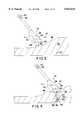
- one known device 10 for enabling a more objective detection of localized areas of stiffer tissue (e.g., lumps) in soft tissue 12presses at least one pair of transducer elements 14, 16 against the soft tissue.
- Each transducer elementgenerates an electrical signal that is proportional to the force imposed on the transducer element.
- transducer element 16lying over the lump, generates an electrical signal indicating the detection of a larger force than transducer element 14, lying over soft tissue alone.
- Device 10calculates the difference between the two electrical signals to determine the presence of lump 20.
- the userdoes not know whether the tissue being examined has any lumps. The user positions and repositions device 10 in an effort to place the transducer elements 14, 16 directly across a boundary of a lump.
- One general aspect of this inventionfeatures examining tissue with a device that includes a transducer element for generating a signal in response to force imposed on the transducer element in accordance with the varying properties of an underlying tissue structure as the transducer element is pressed against and moved over the tissue, and circuitry for detecting a variation in the signal as an indication of a composition of the underlying tissue structure.
- Implementationsmay include one or more of the following features.
- a processordetermines whether the transducer element has been moved over a localized area of stiffer tissue (such as a lump) within the underlying tissue structure (e.g., breast tissue). This is done by comparing the detected variation in the signal to a threshold-which may be constant, variable, or a selected signal pattern. When the detected variation exceeds the threshold, the user is notified that a localized area of stiffer tissue has been detected. For example, a light emitting diode is illuminated and/or a sound generator is actuated.
- a pressure sensing circuitdetects whether the force imposed on the transducer element exceeds a minimum and/or maximum threshold (either or both of which may be variable). The user is notified (such as with a light or sound alarm) when the force imposed on the transducer element is below the minimum threshold and/or above the maximum threshold.
- the variation in the detected signalmay be the rate of change of the signal generated by the transducer element.
- the transducer elementis, for example, a carbon microphone.
- the detecting circuitry and the processormay include analog circuitry, a microprocessor, or both.
- a single transducer elementis used.
- the rate of change of the transducer-generated signalis determined by a dual differentiator circuit, which takes a second derivative of the transducer-generated signal.
- An integratormay be provided for integrating the second derivative obtained by the dual differentiator circuit, or not.
- the tissue examination deviceincludes multiple transducer elements, and variations in the signals generated by the multiple transducer elements are detected as an indication of a composition of the underlying tissue structure.
- Implementationsmay include one or more of the following features.
- the difference between the signals generated by the transducer elementsis determined (e.g., one signal is subtracted from the other), and the variation in the difference is detected as the indication of the underlying tissue structure composition.
- the detected variationis compared to a constant or variable threshold.
- the variationmay be compared with a predetermined pattern to determine whether at least one transducer element has been moved over the localized area of stiffer tissue within the underlying tissue structure.
- the detected variationcan also be compared to predetermined patterns to determine the type of localized area of stiffer tissue over which the device has been moved.
- the rate of change of the difference between the transducer-generated signalsis determined by a differentiator, which takes a derivative of the difference between the signals generated by the transducer elements to detect the rate of change of the difference between the signals generated by the transducer elements.
- the detecting circuitrymay also include an integrator for integrating the derivative.
- the tissue examination devicecan be housed in any way suitable for moving the transducer elements over the tissue.
- the tissue examination devicemay be disposed in a hand-held housing or on a glove, adhesive strip, etc. to allow the user to move the transducer elements manually over the tissue.
- the devicemay include a roller ball assembly for facilitating movement.
- the tissue examination devicemay include a mechanism, attached to the transducer elements, for automatically moving the transducer elements over the tissue.
- the transducer elementsmay be configured as multiple pairs of transducer elements and/or multiple arrangements of two pairs of transducer elements in orthogonal configurations. In this case, the difference between the signals generated by each pair of transducer elements is determined, and the variations in these differences are detected to provide an indication of the composition of the underlying tissue structure.
- a velocity measuring devicemay also be included for measuring the velocity with which the transducer elements are moved over the tissue. In this case, the variations in the differences between the signals of each pair of transducer elements are coordinated with signals produced by the velocity measuring device to provide spacial information regarding the location of the localized area of stiffer tissue within the underlying tissue structure, which is displayed to the user on a display device.
- the inventionfeatures a roller ball assembly including a roller ball and multiple transducer elements, in contact with the roller ball, for generating signals in response to forces imposed on the transducer elements as the roller ball is pressed against and moved over the tissue.
- the assemblyfurther includes circuitry for determining a resulting force vector and force vector angle from the signals generated by the transducer elements as an indication of a composition of the underlying tissue structure.
- Implementationsinclude one or more of the following features.
- the assemblyincludes circuitry for detecting a variation in the force vector angle as an indication of a composition of the underlying tissue structure.
- the transducer elementsare strain instrumented springs.
- the amount of tissue to be examinedis much larger than the size of any possible localized areas of stiffer tissue in the tissue. Moving one or more transducer elements over the tissue to be examined increases the likelihood that a boundary of a localized area of stiffer tissue in the underlying tissue will be crossed and the localized area of stiffer tissue will be detected. Moving one or more transducer elements also allows more tissue area to be covered in a smaller amount of time.
- the difference in the force imposed on a transducer element as it crosses the boundary of a localized area of stiffer tissueis typically small and may be difficult to detect.
- a variation, for instance, the rate of change, in the force imposed on one transducer element or in the difference in force imposed on multiple transducer elementsmay be large as one or more transducer elements pass over the boundary of a localized area of stiffer tissue within the underlying tissue.
- detecting a variation in the signal generated by one or more transducer elementsenhances the detection of localized areas of stiffer tissue.
- detecting a predetermined pattern in a variation of the signal generated by one transducer element or in a variation of the difference between signals generated by multiple transducer elementsmay be used to determine the type of localized area of stiffer tissue that has been detected.
- the useris also not required to interpret complex data to detect possible localized areas of stiffer tissue. Instead, the user is notified of possible localized areas of stiffer tissue through the flash of a light, a tone, or vibration.
- Using multiple transducer assembliesincreases the required signal processing circuitry but may decrease the amount of time required to thoroughly examine a region of soft tissue, e.g., a breast.
- the data from an array of transducer assembliesmay be acquired and coordinated with respect to the locations of the transducer assemblies to map the location and configuration of any detected localized area of stiffer tissue or boundary of a localized area of stiffer tissue.
- the use of an array of transducer elementsalso permits more sophisticated detection methods, as well as, strategies for reducing the incidence of false positive and false negative indications.
- the tissue examination deviceis particularly useful in examining tissue using a palpating motion. For instance, to find localized areas of stiffer tissue (e.g., lumps) during breast self-examinations, one or more transducer elements may be moved in a palpating motion similar to that used during normal breast palpation. Additionally, the transducer elements enhance the effectiveness of self-examinations by detecting localized areas of stiffer tissue that are smaller than those typically detectable by normal breast palpation (e.g., 1 cm).
- FIG. 1is a cross-sectional side view of a pair of transducer elements.
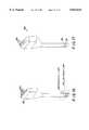
- FIGS. 2 and 3are perspective views showing the use of a tissue examination device.
- FIG. 4is a cross-sectional side view of a transducer assembly of the tissue examination device of FIGS. 2 and 3.
- FIG. 5is a block diagram of a signal processor of the tissue examination device of FIGS. 2 and 3 and the transducer assembly of FIG. 4.
- FIGS. 6A-6Care schematic diagrams of the block diagram of FIG. 5.
- FIG. 6shows the interrelationship between FIGS. 6A-6C.
- FIGS. 7-12are graphs useful in understanding the operation of the tissue examination device of FIGS. 2 and 3.
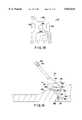
- FIG. 13is a perspective view of another tissue examination device connected to digital circuitry.
- FIG. 14is a cross-sectional side view of another transducer assembly including a single transducer element.
- FIG. 15is a block diagram of another signal processor and the transducer assembly of FIG. 13.
- FIG. 16is a perspective view of yet another tissue examination device including multiple transducer assemblies.
- FIG. 17is a perspective view of yet another tissue examination device including multiple transducer assemblies.
- FIG. 18is a plan view of a transducer assembly including two transducer elements in an orthogonal configuration.
- FIG. 19is a perspective view of yet another tissue examination device including a velocity measuring device.
- FIG. 20is a plan view of a tissue examination device mounted to a glove.
- FIGS. 21 and 22are cross-sectional side and top views, respectively, of a roller ball tissue examination device.
- FIG. 23is a perspective view of a roller ball and two rollers.
- FIG. 24is a cross-sectional side view of an automatic tissue examination device.
- tissue examination device 34to detect localized areas of stiffer tissue, e.g., lump 30, in soft tissue 32, e.g., breast tissue, tissue examination device 34 includes a transducer assembly 36 mounted on one end of a housing 38 and a signal processor 66 (shown in FIGS. 5,6 and 6a-6c, discussed below) for detecting lump 30 based on electrical signals produced by transducer assembly 36 as it is pressed against (arrows 40) and moved along (arrows 42 and 44) a surface 46 of the tissue. Tissue examination device 34 also includes a pair of light emitting diodes (LEDs) 48, 50 at the opposite end of housing 38 and controlled by signal processor 66 for providing the user with feedback during the examination.
- LEDslight emitting diodes
- tissue examination device 34The operation of tissue examination device 34 is described in detail below, but briefly, if signal processor 66 detects a localized area of stiffer tissue, such as lump 30, it illuminates LED 50 (and optionally emits a sound) to notify the user that a lump may be present. The user may perform a manual examination of the tissue with his/her fingers before (or simultaneously with) the transducer examination. The user may then re-perform a manual examination of the tissue with his/her fingers as a double check and/or see a doctor for further examination.
- signal processor 66detects a localized area of stiffer tissue, such as lump 30, it illuminates LED 50 (and optionally emits a sound) to notify the user that a lump may be present.
- the usermay perform a manual examination of the tissue with his/her fingers before (or simultaneously with) the transducer examination. The user may then re-perform a manual examination of the tissue with his/her fingers as a double check and/or see a doctor for further examination.
- signal processor 66illuminates LED 48 (and optionally emits a sound) as a notification to the user that additional pressure is required.
- transducer assembly 36includes two transducer elements 52, 54.
- Transducer elements 52, 54are in effect carbon microphones.
- Each transducer elementincludes two electrode strips: element 52 includes electrode strips 56 and 58; and element 54 includes electrode strips 58 and 60.
- Electrode strips 56, 58, and 60are mounted on an insulating substrate 61, covered with a thin layer, e.g., 0.010", of activated charcoal granules 62, and then sealed with a thin, e.g., 0.005", plastic cover 64.
- each pair of electrodes 56 and 58, and 58 and 60decreases as the force imposed on each transducer element 52, 54 increases.
- Force over the finite area of the transducer elementsis equivalent to the pressure/stress imposed on the transducer elements. Therefore, the term "force,” as used herein, includes both force and pressure.
- the force imposed on transducer elements 52, 54increases when the element passes over localized areas of stiffer tissue (e.g., lump 30, milk ducts, scar tissue, ribs, etc.) within or below tissue 32. Consequently, as device 34 is pressed against and moved along tissue 32, the force imposed on transducer elements 52, 54 and, thus, the resistance of the transducer elements, varies in accordance with the underlying tissue structure.
- signal processor 66receives the electrical signals indicative of force from transducer assembly 36 and determines whether a possible localized area of stiffer tissue is within tissue 32 and whether sufficient pressure is being applied between transducer assembly 36 and tissue 32. More specifically, each transducer element 54, 52 sends an electrical signal 68, 70, respectively, that is related to the force imposed on each transducer element, to subtractor 71 which determines the difference in the force imposed on each transducer element 52, 54 and generates difference signal 86. Because the two transducer elements are closely spaced (e.g., 0.020", i.e., width W, FIG. 4, of electrode strip 58), determining the difference in force imposed on each transducer element 52, 54 removes the contributions of absolute force level (i.e., the pressure applied by the user to tissue examination device 34) from difference signal 86.
- absolute force leveli.e., the pressure applied by the user to tissue examination device 34
- Differentiator/integrator 92(diff./int.) operates on difference signal 86 to provide an enhanced signal 94 representing the rate of change of the difference in force imposed on the transducer elements.
- the difference in force imposed on transducer elements 52, 54may be small.
- the rate of change of the difference in force imposed on transducer elements 52, 54is generally large as the transducer elements cross over a boundary of a localized area of stiffer tissue.
- Differentiator 300within differentiator/integrator 92 detects the large rate of change in difference signal 86 but is, in effect, a noise enhancing unit.
- enhanced signal 94is also integrated by integrator 302 (R7/C1/U1B, FIG. 6B) within differentiator/integrator 92 to reduce the noise enhancing effect of differentiator 300.
- Differentiator/integrator 92performs as a combination of a low-pass filter with a cut-off frequency determined by the R-C combination of R8/C1/U1B in FIG. 6B, together with a high-pass filter with a cut-off frequency determined by the R-C combination of R7/C2/U1B in FIG. 6B.
- the net result of the superpositionis a frequency response curve of the type shown in FIG. 11.
- Enhanced signal 94 produced by differentiator/integrator 92is operated on by absolute value circuit 98, and output signal 100 of absolute value circuit 98 is operated on by comparator 102.
- Comparator 102compares output signal 100 to threshold signal 104. If output signal 100 exceeds threshold signal 104, then tissue examination device 34 has detected a possible localized area of stiffer tissue (e.g., lump 30, FIG. 3) and alarm 110 notifies the user.
- the thresholdis used to avoid false positive alarms.
- Soft tissuefor example, breast tissue, normally varies in composition, having varying properties, e.g., elastic properties. Some areas of gradually varying properties, that is, areas without sharp boundaries, are expected. These areas cause only a small rate of change in the force difference between transducer elements 52, 54, and, as a result, output signal 100 remains low.
- the threshold signalis set at a value which is larger than the value expected for output signal 100 when transducer assembly 36 passes over gradually varying areas. Care must be taken that the threshold signal is not set so high as to mask (i.e., prevent detection of) localized areas of stiffer tissue of concern.
- Signal processor 66also includes pressure detector 111 for determining whether sufficient pressure is being applied by the user to tissue examination device 34 (FIG. 3).
- Electrical signals 76, 78are inversely related (described below) to the force imposed on transducer elements 54, 52, respectively. Hence, as the forces imposed on transducer elements 54, 52 decrease, the values of electrical signals 76, 78 increase.
- Comparators 114, 116compare electrical signals 76, 78, respectively, to a threshold signal (e.g., 121). If either electrical signal 76 or 78 exceeds threshold signal 121, then insufficient pressure is being applied between transducer assembly 36 and tissue 32 and alarm 128 notifies the user.
- FIGS. 6 and 6A-6Cillustrates signal processor 66 in greater detail.
- Signals 68, 70, from transducer elements 54, 52, respectively,are negative voltage signals and are operated on by isolation amplifiers 72, 74, respectively.
- Isolation amplifiers 72, 74electrically isolate signals 68, 70 from each other and invert signals 68, 70 such that resulting output signals 76, 78, are positive voltage signals which are inversely related to the force imposed on transducer elements 54, 52, respectively.
- Signal 76is operated on by a second isolation amplifier 80 which re-inverts signal 76 such that resulting output signal 82 is again a negative voltage signal and related (i.e., approaching zero as force increases) to the force imposed on transducer element 54.
- Signals 78 and 80are summed by adder 84, thereby deriving difference signal 86. Because signal 78 is inversely related to the force imposed on transducer element 52 while signal 80 is related to the force imposed on transducer element 54, adder 84, in effect, takes the difference between signals 78 and 80. Hence, difference signal 86 represents the difference in force imposed on transducer elements 52, 54.
- difference signal 86represents the difference in force ( ⁇ f) imposed on transducer elements 52, 54 over the difference in distance ( ⁇ x) between transducer elements 52, 54.
- the difference in distance ( ⁇ x)is equal to the width W, FIG. 4, of electrode strip 58.
- difference signal 86represents the time course of difference in force imposed on transducer elements 52, 54.
- difference signal 86approximates the first spatial derivative of force (df/dx) imposed on transducer elements 52, 54 modified by a simple Galilean transformation with velocity (dx/dt), approximately:
- difference signal 86when transducer assembly 36 is stationary, difference signal 86 remains constant because transducer elements 52, 54 remain over the same tissue structure, resulting in no change in the difference in force imposed on transducer elements 52, 54 over time. However, as transducer assembly 36 is moved (arrows 42, 44, FIG. 3), difference signal 86 varies as transducer elements 52, 54 pass over underlying tissue structure having different compositions and properties.
- FIG. 7is a graph of difference signal 86 with respect to time.
- the difference in force imposed on transducer elements 52, 54 when transducer elements 52, 54 are both over soft tissue (positions 88 and 95) or both over lump 30 (position 93)is very small.
- the difference in force imposed on transducer elements 52, 54is larger when transducer element 52 is over lump 30 while transducer element 54 is over soft tissue (position 90) or, oppositely, transducer element 54 is over lump 30 while transducer element 52 is over soft tissue (position 96).
- transducer elements 52, 54move from position 88 to position 90 (or from position 96 to position 95), the rate of change (slopes 91 and 91') of difference signal 86 increases rapidly.
- the rate of change (slopes 97 and 97') of difference signal 86decreases rapidly.
- difference signal 86is operated on by differentiator/integrator 92 which generates enhanced signal 94, approximately:
- FIG. 8is a graph of differentiated difference signal 86 with respect to time.
- Differentiator 300(FIG. 6B) generates peaks 83 and 85 in response to large increases (slopes 91 and 91', FIG. 7) in the rate of change of difference signal 86 and peaks 87 and 89 in response to large decreases (slopes 97 and 97') in the rate of change of difference signal 86.
- FIG. 9is a graph of enhanced signal 94 driven by differentiator/integrator 92 (FIG. 6B). As shown, integrator 302 reduces the noise enhancing effect of differentiator 300.
- integrator 302i.e., a second pole attenuates enhanced signal 94 (i.e., decreasing gain) at higher frequencies. To avoid noise problems the gain is decreased to about zero at approximately 60 Hz.
- the characteristic time constant of differentiator/integrator 92determines the range of frequencies in which the differentiator/integrator will have a peak response.
- the relevant range of frequenciesis based on the size of any localized areas of stiffer tissue (e.g., lump 30, FIG. 3) to be detected and the speed at which tissue examination device 34 (FIGS. 2 and 3) is moved across tissue 32. Because a user or multiple users will generally move tissue examination device 34 across tissue 32 at different speeds during use, a reasonable range of speeds is assumed.
- the graph of FIG. 12represents a model for determining the desired characteristic time constant for differentiator/integrator 92.
- the characteristic time constantis based on the time required to cover the slope of a localized area of stiffer tissue and equals the slope of the localized area of stiffer tissue (estimated as one half the diameter of the localized area of stiffer tissue) divided by a predetermined (estimated) tissue examination device speed.
- the model of FIG. 12indicates that the characteristic time constant for differentiator/integrator 92 should be about 0.1 sec.
- output signal 100 from absolute value circuit 98is a positive signal and threshold signal 104 is a negative signal. Both output signal 100 and threshold signal 104 are connected to pin 12 of U1D within comparator 102. Pin 13 of U1D is connected to ground. Consequently, comparator 102, in effect, compares the difference between output signal 100 and threshold signal 104 to ground. When a sufficiently high rate of change in the difference in force imposed on transducer elements 52, 54 is detected, output signal 100 is sufficiently positive to make the difference between output signal 100 and threshold signal 104 positive (i.e., absolute value circuit 98 pulls-up pin 12 of U1D).
- comparator 102drives output signal 108 high, which causes alarm 110 to illuminate LED 50 to notify the user that a possible localized area of stiffer tissue has been detected.
- Alarm 110may also include a piezo buzzer 112 that emits a tone or sound when output signal 108 is driven high by comparator 102.
- FIG. 10is a graph of output signal 100 driven by absolute value circuit 98.
- absolute value circuit 98inverts negative peaks 87 and 89 to provide all positive peaks 83, 87', 89', and 85 to comparator 102.
- Comparator 102compares peaks 83, 87', 89', and 85 to single threshold signal 104 (line 99). Because peaks 83, 87', 89', and 85 exceed threshold signal 104, comparator 102 drives output signal 108 high four times to cause alarm 110 to notify the user with four LED 50 pulses (or tones) that a possible localized area of stiffer tissue has been detected.
- Threshold signal 104may be a fixed value or, as shown, may be varied through threshold control circuit 106, e.g., variable resistor 107 connected to a knob (not shown). Threshold control 106 allows a user, preferably a physician with skill and training, to alter threshold signal 104 in accordance with the physiology of a particular user of tissue examination device 34. For example, breast tissue of older women often contains localized areas of stiffer tissue with gradually varying properties (i.e., gradual boundaries), for instance, fibrous structures, calcified milk ducts, or scar tissue.
- threshold signal 104When examining such tissue, a physician may wish to increase threshold signal 104 such that alarm 110 indicates only detected localized areas of stiffer tissue which have quickly changing properties (i.e., sharp boundaries associated with lumps). Conversely, some breast tissue does not contain (or contains very few) localized areas of stiffer tissue with gradually varying properties, and the physician may wish to lower threshold signal 104 such that alarm 110 indicates any detected localized areas of stiffer tissue.
- comparator 114compares the difference between isolated signal 76 and threshold signal 118 (pin 3 of U4A) to ground (pin 2 of U4A), and comparator 116 compares the difference between isolated signal 78 and threshold signal 120 (pin 12 of U2D) to ground (pin 13 of U2D). Because signals 76 and 78 are inversely proportional to the force applied to transducer elements 54, 52, respectively, as the force decreases, the voltage of signals 76 and 78 become more positive.
- variable threshold control 123provides adjustable threshold signal 121.
- a physicianmay use adjustable threshold signal 121 to modify the pressure threshold in accordance with the physiology of a particular user.
- jumper 129(FIG. 6C) connects lockout signal 130 from alarm 128 to alarm 110. If the user is applying insufficient pressure to tissue examination device 34, lockout signal 130 is low and alarm 110 is prevented from notifying a user of lump 30 in tissue 32. This reduces false positive signals that may be generated, for example, when the device is first brought in contact with the tissue.
- pressure detector 111may also include circuitry for determining whether too much pressure is being applied by the user to tissue examination device 34.
- the electrical signals 76, 78may be compared to a minimum threshold and a maximum threshold which establish a range of acceptable levels. If the electrical signals 76, 78 are not within the range of acceptable levels, then alarm 128 notifies the user to increase or decrease the pressure being applied.
- Carbon microphone transducer elements 52, 54may be replaced by any suitable force sensitive elements. Examples include force sensitive resistance transducers based on contact resistance of shunting elements, strain gage based transducers, piezoelectric transducers (e.g., ceramic, electret), capacitive microphone elements, and differential transformers. Additionally, the activated charcoal granules 62 (FIG. 4) may be replaced with saline to provide a saline microphone.
- transducer elements 52, 54may be replaced by pressure sensitive elements.
- one pressure sensitive assemblyincludes two inflatable pockets or bubbles attached to a differential pressure transducer. As the pockets are pressed against the tissue to be examined, the pockets apply pressure to the differential pressure transducer in accordance with the varying properties of the underlying tissue structure. The differential pressure transducer determines the difference in pressures applied by each pocket, and circuitry similar to that describe above detects variations in the difference in pressures to detect localized areas of stiffer tissue in the tissue being examined.
- the signal processing used to detect the boundaries of localized areas of stiffer tissueneed not be constrained to determining the rate of change of the difference in the electrical signals generated by the transducer elements. Many variations in the electrical signals generated by the transducer elements may be used to detect localized areas of stiffer tissue, and many methods exist for detecting these variations.
- difference signal 86(FIG. 5) is a periodically varying signal. Periodically varying signals may be reduced through Fourier transforms to the sum of multiple sine waves where each sine wave has a particular frequency, amplitude, and phase angle. Instead of detecting a rate of change of the difference in force applied to each transducer element, the frequency, amplitude, or phase angle of a component of the difference signal may be determined and used to detect localized areas of stiffer tissue.
- the analog circuitry of FIG. 6Bmay be replaced with different analog circuitry.
- differentiator/integrator 92FIGGS. 5 and 6
- Such a circuitalso has an increasing gain with increasing frequency followed by a reduction in gain at higher frequencies.
- the analog circuitry of FIGS. 6 and 6A-6Cmay also be replaced with digital circuitry including a microprocessor and/or a digital signal processor 350 directly connected to transducer assembly 36 through electrical signals 68, 70.
- the digital circuitrymay sample electrical signals 68, 70 from transducer elements 52, 54 and process the sampled data sequentially with, for example, a finite-impulse-response (FIR) filter or similar techniques to enhance the signals.
- FIRfinite-impulse-response
- the digital circuitrymay then notify the user of any detected possible localized areas of stiffer tissue through LEDs 48, 50.
- the digital circuitrymay also provide a "learning mode."
- learning modean individual user is examined to determine the characteristics of signals corresponding to tissue areas without localized areas of stiffer tissue. These characteristics are then used to determine the thresholds for localized areas of stiffer tissue detection with respect to the individual user.
- the thresholds and characteristicsare then stored in memory (e.g., EEPROM) attached to the microprocessor and/or digital signal processor for use during subsequent examinations.
- the analog or digital circuitrymay provide a self-test mode. For instance, when the tissue examination device is first powered-up, the circuitry may run a self-test procedure to insure that the circuitry is performing properly. The user may also be involved in the self-test procedure. For example, the user may be signaled (through an LED or sound) to press the transducer assembly against a smooth, flat surface. This allows the circuitry to determine whether the transducer assembly is also performing correctly.
- a user or health care professionalmay compare the results of different exams to determine whether new thickened areas have developed and to determine whether known thickened areas have changed in size. For example, once a thickened area is detected, in the next examination, a user may place the tissue examination device over the same area to determine whether the thickened area has grown.
- a digital implementationmay allow for the storage or permanent record of the results of examinations as well as other information such as date and time of examinations. This information may then be read out at regular intervals to provide a record of longer term trends. This information may also be used to provide an automatic comparison of the results between different examinations.
- Comparator 102may further include circuitry for pattern recognition, such as a particular sequence of peaks, e.g., 83, 87', 89', and 85 (FIG. 10).
- the patternmay be used as a threshold (e.g., a localized area of stiffer tissue is not detected unless the pattern is matched), or the pattern may be used to represent particular types of detected localized areas of stiffer tissue. For example, a pattern for a cyst may be quite different from a pattern for a solid breast lump.
- alarm 110may notify the user of the particular pattern recognized, for instance, through a series of LEDs or a series of tones or on a display screen.
- transducer assembly 36'may include a single transducer element 130.
- Single transducer element 130includes a single pair of electrode strips 132, 134 mounted on an insulating substrate 136, covered with a thin layer of activated charcoal 138, and sealed with a thin plastic coating 140.
- transducer element 130sends a signal 142, that is related to the force imposed on transducer element 130, to an isolation amplifier 74 within signal processor 66'.
- Output signal 146 of isolation amplifier 74is operated on by dual differentiator/integrator 148 (dual diff./int.).
- the dual differentiatortakes the second derivative of output signal 146 and generates enhanced signal 150, approximately:
- the second order derivative(dual differentiator/integrator) has a transfer function similar to that of a band-pass filter as shown in FIG. 11.
- Enhanced signal 150may be operated on by absolute value circuit 98 in the manner described above with respect to enhanced signal 90. Additionally, comparator 102, threshold control 106, and alarm 110 operate as described above. Signal processor 66' also includes pressure detector 111' which operates in a manner similar to pressure detector 111 (FIG. 5).
- tissue examination device 180may include multiple transducer assemblies 182 including one or more transducer elements. With such an arrangement, the circuitry of signal processor 66 (FIG. 5) or 66' (FIG. 14) is replicated for each transducer assembly 182. Localized area of stiffer tissue alarm 110 may then notify the user (through LED 50 and/or a sound) when any of the transducer assemblies 182 detect a possible localized area of stiffer tissue, e.g., lump 30 (FIG. 3). Alternatively, alarm 110 may include additional circuitry which requires that two or more adjacent transducer assemblies 182 detect a possible localized area of stiffer tissue before the user is notified.
- signal processor 66FIG. 5
- 66'FIG. 14
- Localized area of stiffer tissue alarm 110may then notify the user (through LED 50 and/or a sound) when any of the transducer assemblies 182 detect a possible localized area of stiffer tissue, e.g., lump 30 (FIG. 3).
- alarm 110may include additional circuitry which
- the tissue examination devicemay have detected a large scale structure unrelated to possible localized areas of stiffer tissue, such as a rib.
- the tissue examination devicemay be traversing a large scale structure (i.e., a rib or milk duct) at an angle.
- tissue examination device 183may also include multiple transducer assemblies 185 including one or more transducer elements.
- the transducer assemblies 185are arranged in a two-dimensional grid, however, many other arrangements are possible.
- a configuration of multiple transducer assembliesmay allow a more complex pattern recognition methodology to be employed.
- transducer assembly 36"may include two (or more) pairs of transducer elements.
- one pair of transducer elementsincludes electrode strips 184, 186, and 188, while another pair of transducer elements includes electrode strips 190, 186, and 192.
- these two transducer pairsare orthogonal.
- the data received from each transducer pairmay be compiled by a microprocessor and coordinated with the locations of the transducer pairs with respect to each other to map the location and configuration of any detected localized area of stiffer tissue or boundary of a localized area of stiffer tissue.
- the signal processingmay also be accomplished through an analog circuit. This orthogonal configuration is particularly effective in detecting localized areas of stiffer tissue during the quasi-circular motion recommended for manual breast self-examination.
- a velocity measuring devicefor example, roller ball 194 may also be mounted on housing 38 of tissue examination device 34 and electrically connected to signal processor 66".
- the measured velocitymay be integrated to indicate the position of the tissue examination device with respect to the tissue being examined, and using the measured velocity of the tissue examination device, the signal processor may map out the location of a localized area of stiffer tissue or boundary of a localized area of stiffer tissue within the tissue being examined. Using the measured velocity, the signal processor may also better carry out pattern recognition.
- the velocity measuring devicemay be replaced with an accelerometer for measuring the acceleration of the tissue examination device as it is moved over the tissue.
- the measured accelerationmay be integrated twice to indicate the position of the tissue examination device with respect to the tissue being examined.
- the velocity measuring devicemay be replaced with a position tracking system using, for instance, ultrasound or radio frequency.
- tissue examination device housing 38may be rounded and transducer assembly 36 may also be rounded to facilitate movement of the transducer assembly over the tissue to be examined. Additionally, transducer assembly 36 (FIG. 2) may be mounted on a variety of devices designed to facilitate the movement of the transducer assembly across a surface of tissue 32.
- transducer assembly 36may be mounted on the outside of finger tip 196 (or any other finger tip) of a glove 198, while signal processor 66 may be secured within housing 200 mounted on wrist 202 of glove 198 (or elsewhere on the glove or separate from the glove).
- the userwhile wearing the glove, nay perform manual breast palpation, which the user may already be familiar and comfortable with, and receive the additional benefits, e.g., small localized area of stiffer tissue detection, of transducer assembly 36.
- the user's adjacent fingerscan be used to detect localized areas of stiffer tissue as in a normal breast self-exam, or one or more of the adjacent fingers of glove 198 may also be mounted with transducer assemblies 36.
- the transducer assemblymay simply be adhered by, for example, an adhesive strip to the user's finger.
- tissue examination device 210includes housing 212 which captures and supports roller ball 214 while still allowing roller ball 214 to turn freely.
- Three strain instrumented springs 216, 218, and 220are attached at one end to a central support member 222 and are attached at the other end to three rollers 224, 226, and 228, respectively.
- Rollers 224, 226, and 228roll across a surface of roller ball 214 and are biased toward the surface of the roller ball by strain instrumented springs 216, 218, and 220.
- each roller 224, 226, 228measures the force imposed in a direction perpendicular to the roller ball.
- a force vector 224', 226', 228'(only 224' and 226' are shown) is associated with each roller 224, 226, and 228, respectively. If the roller ball is pushed against a flat hard surface, then the resulting force vector 229 (i.e., the combination of force vectors 224', 226', and 228') is vertical and equal to the force imposed on the roller ball.
- the resulting force vector 229' leans(arrow 231) backward due to friction between the roller ball and the surface.
- the resulting force vector angle 232changes in accordance with the varying properties of the underlying tissue structure.
- the horizontal component of the resulting force vectoris operated upon by processing circuitry 238 to determine force variations in space which indicate possible localized areas of stiffer tissue in the underlying tissue.
- the forces imposed by the roller ball on the rollersmay be detected in many ways, including, for example, replacing the strain instrumented springs with simple biasing springs and the rollers with force sensing rollers.
- the roller ballmay be biased toward the tissue to be examined through many different mechanisms.
- an automatic tissue examination device 250may be provided.
- Automatic device 250includes a flexible membrane 252, which is pressed (arrows 253 and 255) against tissue 254 to be examined, and a mechanism 256 for moving (arrows 258, 260, 262) a force sensing device 264, for example, a roller ball configuration similar to that described with respect to FIGS. 21-23. Automatic device 250 may then move the force sensing device across the tissue to be examined at a constant, known velocity in a manner designed to effectively and efficiently examine the tissue.
- the above described tissue examination devicesmay be electrically connected to a display device (e.g., 270, FIG. 24) for displaying information about the electrical signals generated by the transducer elements.
- the display devicemay display waveforms, for example, of the type shown in FIGS. 7-10, or the display may show the locations of possible localized areas of stiffer tissue or a map of the tissue being examined.
- tissue examination devicesmay be applied directly to the surface of the tissue to be examined, or the surface of the tissue to be examined may be coated with a lubricant to help the devices glide easily over the tissue surface. Additionally, the devices may be waterproof allowing the device to be used while in the shower or bath tub.
- a tissue examination deviceincludes a disposable cap 310 (FIG. 13).
- the capincludes a smooth, thin, e.g., 0.005", flexible plastic sheet 312 on an end 314. Plastic sheet 312 does not substantially impede the force response of transducer assembly 36.
- transducer assembly 36is mounted within the disposable cap and includes an electrical connector for connecting the transducer assembly to the tissue examination device when the cap is attached to the tissue examination device.
- alarm 110may produce an audible tone if a localized area of stiffer tissue is detected.
- an audio or visual indicatormay continuously produce sound or light and vary that sound or light according to the rate of change (or other variation) of the difference in force imposed on each of the transducer elements. For example, a higher pitched tone (or louder tone) may be produced when the boundary of a localized area of stiffer tissue is crossed. The pitch of the tone may also vary according to the type of localized area of stiffer tissue detected.
- the tissue examination devicecould vibrate.
- the light, sound, or vibrationmay be generated for a fixed period of time.
- tissue examination device 34(FIG. 2) over tissue 32 is typically accomplished in one of two ways: shear or non-shear movement.
- Shear movementoccurs when tissue examination device 34 moves over tissue 32, as well as, surface 46.
- the dominant deformation strainis compression and shearing stress. Lubrication may assist shear movement.
- Non-shear movementoccurs when friction between tissue examination device 34 and surface 46 does not allow tissue examination device 34 to move over surface 46 but, because the tissue is soft and flexible, tissue examination device 34 still moves over portions of tissue 32.
- the dominant deformation strainis compression and elongation.
- the likelihood that a localized area of stiffer tissue will be detectedmay be increased by establishing different detection thresholds for the two different types of movement, and threshold control 106 (FIG. 5) may be used to adjust the detection threshold in accordance with the planned type of movement.
- processing circuitry 66may include different localized area of stiffer tissue detection circuitry for the two different types of movement and a mode switch to select between the two different circuits.
- the devices described abovemay be used in a variety of applications.
- the devicesmay be used to find localized areas of stiffer tissue in breast tissue, the prostate, the testicles, or the mouth.
- the devicesmay be used to examine the abdomen to find, for example, enlarged ovaries or tumors.
- the devicesmay be used to examine tissue to locate arteries or veins for needle placement.
Landscapes
- Health & Medical Sciences (AREA)
- Life Sciences & Earth Sciences (AREA)
- Biomedical Technology (AREA)
- Molecular Biology (AREA)
- Veterinary Medicine (AREA)
- Biophysics (AREA)
- Pathology (AREA)
- Engineering & Computer Science (AREA)
- Public Health (AREA)
- Heart & Thoracic Surgery (AREA)
- Medical Informatics (AREA)
- Physics & Mathematics (AREA)
- Surgery (AREA)
- Animal Behavior & Ethology (AREA)
- General Health & Medical Sciences (AREA)
- Gynecology & Obstetrics (AREA)
- Reproductive Health (AREA)
- Measuring And Recording Apparatus For Diagnosis (AREA)
- Ultra Sonic Daignosis Equipment (AREA)
Abstract
Description
(Δf/Δx)(dx/dt)≈(df/dx)(dx/dt)=df/dt.
d/dt(df/dt)=d.sup.2 f/dt.sup.2.
d/dt(df/dt)=d.sup.2 f/dt.sup.2.
Claims (104)
Priority Applications (5)
| Application Number | Priority Date | Filing Date | Title |
|---|---|---|---|
| US08/556,161US5833634A (en) | 1995-11-09 | 1995-11-09 | Tissue examination |
| CA002236978ACA2236978A1 (en) | 1995-11-09 | 1996-10-22 | Tissue examination device and method |
| PCT/US1996/017173WO1997017017A1 (en) | 1995-11-09 | 1996-10-22 | Tissue examination device |
| EP96939498AEP0873079A4 (en) | 1995-11-09 | 1996-10-22 | Tissue examination device |
| JP9518213AJP2000500039A (en) | 1995-11-09 | 1996-10-22 | Tissue examination apparatus and method |
Applications Claiming Priority (1)
| Application Number | Priority Date | Filing Date | Title |
|---|---|---|---|
| US08/556,161US5833634A (en) | 1995-11-09 | 1995-11-09 | Tissue examination |
Publications (1)
| Publication Number | Publication Date |
|---|---|
| US5833634Atrue US5833634A (en) | 1998-11-10 |
Family
ID=24220152
Family Applications (1)
| Application Number | Title | Priority Date | Filing Date |
|---|---|---|---|
| US08/556,161Expired - LifetimeUS5833634A (en) | 1995-11-09 | 1995-11-09 | Tissue examination |
Country Status (5)
| Country | Link |
|---|---|
| US (1) | US5833634A (en) |
| EP (1) | EP0873079A4 (en) |
| JP (1) | JP2000500039A (en) |
| CA (1) | CA2236978A1 (en) |
| WO (1) | WO1997017017A1 (en) |
Cited By (56)
| Publication number | Priority date | Publication date | Assignee | Title |
|---|---|---|---|---|
| WO1999020178A1 (en)* | 1997-10-20 | 1999-04-29 | Assurance Medical, Inc. | Layer of material for use with tissue examination device |
| US5916180A (en)* | 1997-10-03 | 1999-06-29 | Uromed Corporation | Calibrating pressure sensors |
| US5989199A (en)* | 1996-11-27 | 1999-11-23 | Assurance Medical, Inc. | Tissue examination |
| WO2000017838A1 (en)* | 1998-09-24 | 2000-03-30 | West Virginia University | Instrumented breast model |
| US6063031A (en)* | 1997-10-14 | 2000-05-16 | Assurance Medical, Inc. | Diagnosis and treatment of tissue with instruments |
| USD425980S (en)* | 1997-10-20 | 2000-05-30 | Assurance Medical, Inc. | Hand-held tissue examination device |
| US6091981A (en)* | 1997-09-16 | 2000-07-18 | Assurance Medical Inc. | Clinical tissue examination |
| WO2000071023A1 (en)* | 1999-05-24 | 2000-11-30 | Rbp, Inc. | Method and apparatus tissue imaging |
| US6192143B1 (en)* | 1997-10-24 | 2001-02-20 | Ultratouch Corporation | Apparatus for detecting very small breast anomalies |
| US6314315B1 (en)* | 1999-01-13 | 2001-11-06 | Pro Duct Health, Inc. | Ductal orifice identification by characteristic electrical signal |
| US6351549B1 (en) | 1997-10-24 | 2002-02-26 | Ultratouch Corporation | Detection head for an apparatus for detecting very small breast anomalies |
| US6424852B1 (en)* | 1996-10-18 | 2002-07-23 | Lucid, Inc. | System for confocal imaging within dermal tissue |
| US6468231B2 (en) | 2000-03-31 | 2002-10-22 | Artann Laboratories | Self-palpation device for examination of breast |
| US20020178833A1 (en)* | 2001-04-04 | 2002-12-05 | Siemens Medical System, Inc | Method and system for improving the spatial resolution for strain imaging |
| US20030031993A1 (en)* | 1999-08-30 | 2003-02-13 | Carla Pugh | Medical examination teaching and measurement system |
| US6524246B1 (en) | 2000-10-13 | 2003-02-25 | Sonocine, Inc. | Ultrasonic cellular tissue screening tool |
| US6595933B2 (en) | 2000-03-31 | 2003-07-22 | Artann Laboratories | Self-palpation device for examination of breast with 3-D positioning system |
| US20040030672A1 (en)* | 2001-08-01 | 2004-02-12 | Garwin Jeffrey L | Dynamic health metric reporting method and system |
| US20040056653A1 (en)* | 2002-05-24 | 2004-03-25 | Dan Bocek | Linear variable differential transformer with digital electronics |
| US20040122322A1 (en)* | 2002-12-18 | 2004-06-24 | Barbara Ann Karmanos Cancer Institute | Electret acoustic transducer array for computerized ultrasound risk evaluation system |
| US6825838B2 (en) | 2002-10-11 | 2004-11-30 | Sonocine, Inc. | 3D modeling system |
| US20040254503A1 (en)* | 2003-06-13 | 2004-12-16 | Sarvazyan Armen P. | Internet-based system and a method for automated analysis of tactile imaging data and detection of lesions |
| US20040267165A1 (en)* | 2003-06-12 | 2004-12-30 | Sarvazyan Armen P. | Tactile breast imager and method for use |
| US20060178596A1 (en)* | 2005-01-25 | 2006-08-10 | University Of Massachusetts | Cutaneous indentation sensory testing device |
| US20090025475A1 (en)* | 2007-01-24 | 2009-01-29 | Debeliso Mark | Grip force transducer and grip force assessment system and method |
| US20090036779A1 (en)* | 2006-01-24 | 2009-02-05 | National Institute Of Advanced Industrial Science And Technology | Ultrasound diagnostic apparatus |
| US20090124903A1 (en)* | 2004-11-17 | 2009-05-14 | Takashi Osaka | Ultrasound Diagnostic Apparatus and Method of Displaying Ultrasound Image |
| US20100137710A1 (en)* | 1996-10-18 | 2010-06-03 | Zavislan James M | System for marking the locations of imaged tissue with respect to the surface of the tissue |
| US20100152586A1 (en)* | 2008-12-12 | 2010-06-17 | Immersion Corporation | Spatial Array of Sensors Mounted on A Tool |
| US20100179423A1 (en)* | 2009-01-15 | 2010-07-15 | Immersion Corporation | Palpation Algorithms For Computer-Augmented Hand Tools |
| US20100204617A1 (en)* | 2009-02-12 | 2010-08-12 | Shmuel Ben-Ezra | Ultrasonic probe with acoustic output sensing |
| US20110071436A1 (en)* | 2008-06-05 | 2011-03-24 | Kaspar Althoefer | Air cushion sensor for tactile sensing during minimally invasive surgery |
| US20110144501A1 (en)* | 2008-08-19 | 2011-06-16 | Yuushi Nishimura | Ultrasonographic device |
| US8523043B2 (en) | 2010-12-07 | 2013-09-03 | Immersion Corporation | Surgical stapler having haptic feedback |
| US8801710B2 (en) | 2010-12-07 | 2014-08-12 | Immersion Corporation | Electrosurgical sealing tool having haptic feedback |
| US8845555B2 (en) | 2008-05-16 | 2014-09-30 | Drexel University | System and method for evaluating tissue |
| US8845667B2 (en) | 2011-07-18 | 2014-09-30 | Immersion Corporation | Surgical tool having a programmable rotary module for providing haptic feedback |
| US9226979B2 (en)* | 2001-11-19 | 2016-01-05 | Dune Medical Devices Ltd. | Method and apparatus for examining tissue for predefined target cells, particularly cancerous cells, and a probe useful in such method and apparatus |
| US20160026894A1 (en)* | 2014-07-28 | 2016-01-28 | Daniel Nagase | Ultrasound Computed Tomography |
| US9358072B2 (en) | 2010-01-15 | 2016-06-07 | Immersion Corporation | Systems and methods for minimally invasive surgical tools with haptic feedback |
| US20160310006A1 (en)* | 2015-04-24 | 2016-10-27 | Victor Efrain Aguero Villarreal | Device for the Mechanical Detection of Underlying Tissues |
| US9518814B2 (en) | 2008-10-14 | 2016-12-13 | Oxford Instruments Asylum Research Inc | Integrated micro actuator and LVDT for high precision position measurements |
| US9579143B2 (en) | 2010-08-12 | 2017-02-28 | Immersion Corporation | Electrosurgical tool having tactile feedback |
| US9618497B2 (en) | 2004-05-24 | 2017-04-11 | Drexel University | All electric piezoelectric finger sensor (PEFS) for soft material stiffness measurement |
| US9679499B2 (en) | 2008-09-15 | 2017-06-13 | Immersion Medical, Inc. | Systems and methods for sensing hand motion by measuring remote displacement |
| US9763641B2 (en) | 2012-08-30 | 2017-09-19 | Delphinus Medical Technologies, Inc. | Method and system for imaging a volume of tissue with tissue boundary detection |
| US9867668B2 (en) | 2008-10-20 | 2018-01-16 | The Johns Hopkins University | Environment property estimation and graphical display |
| US10074199B2 (en) | 2013-06-27 | 2018-09-11 | Tractus Corporation | Systems and methods for tissue mapping |
| CN108577844A (en)* | 2018-05-18 | 2018-09-28 | 北京先通康桥医药科技有限公司 | The method and system of opening relationships model based on pressure distribution data, storage medium |
| US10123770B2 (en) | 2013-03-13 | 2018-11-13 | Delphinus Medical Technologies, Inc. | Patient support system |
| US10201324B2 (en) | 2007-05-04 | 2019-02-12 | Delphinus Medical Technologies, Inc. | Patient interface system |
| US10285667B2 (en) | 2014-08-05 | 2019-05-14 | Delphinus Medical Technologies, Inc. | Method for generating an enhanced image of a volume of tissue |
| EP3451925A4 (en)* | 2016-05-03 | 2019-12-04 | Texas Medical Center | TACTILE SENSING DEVICE FOR LUMBAR SUNCTIONS |
| US11000311B2 (en) | 2017-10-27 | 2021-05-11 | Intuitap Medical, Inc. | Tactile sensing and needle guidance device |
| US20220095996A1 (en)* | 2020-09-27 | 2022-03-31 | Melissa Patterson | Wearable medical device |
| US11395593B2 (en)* | 2016-09-14 | 2022-07-26 | Mor Research Applications Ltd. | Device, system and method for detecting irregularities in soft tissue |
Families Citing this family (7)
| Publication number | Priority date | Publication date | Assignee | Title |
|---|---|---|---|---|
| US5833634A (en)* | 1995-11-09 | 1998-11-10 | Uromed Corporation | Tissue examination |
| DE19754085A1 (en)* | 1997-12-05 | 1999-06-10 | Helmut Prof Dr Ing Ermert | A sonographic elastography system |
| AU6028299A (en)* | 1998-09-08 | 2000-03-27 | Catholic University Of America, The | Method and system for tactile imaging for breast cancer examination and detection of prostate cancer |
| GB9906759D0 (en)* | 1999-03-24 | 1999-05-19 | Davies Brian | An automatic robotic system for inserting a sharp probe or instrument into a vein |
| US6500119B1 (en)* | 1999-12-01 | 2002-12-31 | Medical Tactile, Inc. | Obtaining images of structures in bodily tissue |
| FR2955478B1 (en)* | 2010-01-25 | 2013-04-12 | Lyon Ecole Centrale | METHOD OF CHARACTERIZING HUMAN TOUCH |
| JP2013528086A (en) | 2010-06-11 | 2013-07-08 | サノフィ−アベンティス・ドイチュラント・ゲゼルシャフト・ミット・ベシュレンクテル・ハフツング | Assembly for drug delivery device and drug delivery device |
Citations (61)
| Publication number | Priority date | Publication date | Assignee | Title |
|---|---|---|---|---|
| US3154789A (en)* | 1963-03-25 | 1964-11-03 | Jr Edward Lewis | Disposable examination garment |
| US3308476A (en)* | 1964-01-21 | 1967-03-07 | Kleesattel Claus | Resonant sensing devices |
| US3323352A (en)* | 1965-01-04 | 1967-06-06 | Branson Instr | Control circuit for resonant sensing device |
| US3744490A (en)* | 1971-11-16 | 1973-07-10 | H Fernandez | Automatic device for recording blood pressure |
| US3847139A (en)* | 1973-04-13 | 1974-11-12 | E Flam | Device for aid in detecting breast cancer |
| US3854471A (en)* | 1972-09-15 | 1974-12-17 | J Wild | Ultrasonic method for systematic search and detection of tissue abnormalities |
| US3880145A (en)* | 1972-10-02 | 1975-04-29 | Stein Paul D | Method and apparatus for continuously monitoring blood pressure |
| US3970862A (en)* | 1974-06-25 | 1976-07-20 | The United States Of America As Represented By The Secretary Of The Navy | Polymeric sensor of vibration and dynamic pressure |
| US3972227A (en)* | 1974-04-05 | 1976-08-03 | Boris Vasilievich Tomilov | Method of ultrasonic measurements |
| US3996922A (en)* | 1973-08-17 | 1976-12-14 | Electronic Monitors, Inc. | Flexible force responsive transducer |
| US4001951A (en)* | 1975-03-25 | 1977-01-11 | Fasse Wolfgang G | Breast cancer detection training device |
| US4023562A (en)* | 1975-09-02 | 1977-05-17 | Case Western Reserve University | Miniature pressure transducer for medical use and assembly method |
| US4025165A (en)* | 1974-10-04 | 1977-05-24 | Yeda Research & Development Co. Ltd. | Electro optical imaging device |
| US4132224A (en)* | 1977-01-12 | 1979-01-02 | Randolph Robert G | Durometer for indentible tissue and the like |
| US4134218A (en)* | 1977-10-11 | 1979-01-16 | Adams Calvin K | Breast cancer detection training system |
| US4135497A (en)* | 1977-03-18 | 1979-01-23 | E-Z-Em Company, Inc. | Apparatus for detecting temperature variations over selected regions of living tissue, and method thereof |
| US4144877A (en)* | 1976-08-12 | 1979-03-20 | Yeda Research And Development Co. Ltd. | Instrument for viscoelastic measurement |
| US4159640A (en)* | 1977-03-04 | 1979-07-03 | L'oreal | Apparatus for measuring the consistency or hardness of a material |
| US4190058A (en)* | 1978-05-22 | 1980-02-26 | Arden Industries, Inc. | Device for use in early detection of breast cancer |
| US4212306A (en)* | 1978-05-18 | 1980-07-15 | Khalid Mahmud | Breast examination device and method |
| US4219708A (en)* | 1979-02-12 | 1980-08-26 | Detectors, Inc. | Shockswitch |
| USRE30446E (en)* | 1979-03-16 | 1980-12-16 | E-Z-Em Company, Inc. | Apparatus for detecting temperature variations over selected regions of living tissue, and method thereof |
| US4250894A (en)* | 1978-11-14 | 1981-02-17 | Yeda Research & Development Co., Ltd. | Instrument for viscoelastic measurement |
| US4286602A (en)* | 1979-06-20 | 1981-09-01 | Robert Guy | Transillumination diagnostic system |
| US4291708A (en)* | 1977-11-02 | 1981-09-29 | Yeda Research & Development Co. Ltd. | Apparatus and method for detection of tumors in tissue |
| GB2086575A (en)* | 1980-07-30 | 1982-05-12 | Colombo Aldo | Temperature-responsive screen to detect temperature anomalies of the skin |
| US4458694A (en)* | 1977-11-02 | 1984-07-10 | Yeda Research & Development Co., Ltd. | Apparatus and method for detection of tumors in tissue |
| US4503865A (en)* | 1981-12-28 | 1985-03-12 | Olympus Optical Co., Ltd. | Hardness measuring probe |
| US4524778A (en)* | 1983-07-01 | 1985-06-25 | American Thermometer Co., Inc. | Skin temperature indicating and recording device |
| USRE32000E (en)* | 1978-05-22 | 1985-10-08 | B.C.S.I. Laboratories, Inc. | Device for use in early detection of breast cancer |
| US4555953A (en)* | 1984-04-16 | 1985-12-03 | Paolo Dario | Composite, multifunctional tactile sensor |
| US4570638A (en)* | 1983-10-14 | 1986-02-18 | Somanetics Corporation | Method and apparatus for spectral transmissibility examination and analysis |
| US4600011A (en)* | 1982-11-03 | 1986-07-15 | The University Court Of The University Of Aberdeen | Tele-diaphanography apparatus |
| US4641661A (en)* | 1985-08-02 | 1987-02-10 | Kalarickal Mathew S | Electronic algesimeter |
| US4641659A (en)* | 1979-06-01 | 1987-02-10 | Sepponen Raimo E | Medical diagnostic microwave scanning apparatus |
| US4651749A (en)* | 1978-05-22 | 1987-03-24 | B.C.S.I. Laboratories, Inc. | Cancer detection patch for early detection of breast cancer |
| US4657021A (en)* | 1985-04-24 | 1987-04-14 | Earl Wright Company | Touch enhancing pad |
| US4729378A (en)* | 1985-11-26 | 1988-03-08 | Interzeag Ag | Apparatus for ascertaining the pressure in a plenum chamber |
| US4737109A (en)* | 1987-03-03 | 1988-04-12 | Abramson Daniel J | Breast cancer detection training device |
| US4768516A (en)* | 1983-10-14 | 1988-09-06 | Somanetics Corporation | Method and apparatus for in vivo evaluation of tissue composition |
| US4774961A (en)* | 1985-11-07 | 1988-10-04 | M/A Com, Inc. | Multiple antennae breast screening system |
| US4793354A (en)* | 1987-10-20 | 1988-12-27 | Inventive Products, Inc. | Touch enhancement |
| US4807637A (en)* | 1984-08-20 | 1989-02-28 | American Science And Engineering, Inc. | Diaphanography method and apparatus |
| US4810875A (en)* | 1987-02-02 | 1989-03-07 | Wyatt Technology Corporation | Method and apparatus for examining the interior of semi-opaque objects |
| US4817623A (en)* | 1983-10-14 | 1989-04-04 | Somanetics Corporation | Method and apparatus for interpreting optical response data |
| US4873982A (en)* | 1988-10-24 | 1989-10-17 | Morrison Judith A | Examination garment |
| US5010772A (en)* | 1986-04-11 | 1991-04-30 | Purdue Research Foundation | Pressure mapping system with capacitive measuring pad |
| US5012817A (en)* | 1989-05-19 | 1991-05-07 | University Of Victoria | Dolorimeter apparatus |
| US5079698A (en)* | 1989-05-03 | 1992-01-07 | Advanced Light Imaging Technologies Ltd. | Transillumination method apparatus for the diagnosis of breast tumors and other breast lesions by normalization of an electronic image of the breast |
| US5099848A (en)* | 1990-11-02 | 1992-03-31 | University Of Rochester | Method and apparatus for breast imaging and tumor detection using modal vibration analysis |
| US5140989A (en)* | 1983-10-14 | 1992-08-25 | Somanetics Corporation | Examination instrument for optical-response diagnostic apparatus |
| US5143079A (en)* | 1989-08-02 | 1992-09-01 | Yeda Research And Development Company Limited | Apparatus for detection of tumors in tissue |
| US5212637A (en)* | 1989-11-22 | 1993-05-18 | Stereometrix Corporation | Method of investigating mammograms for masses and calcifications, and apparatus for practicing such method |
| US5221269A (en)* | 1990-10-15 | 1993-06-22 | Cook Incorporated | Guide for localizing a nonpalpable breast lesion |
| US5265612A (en)* | 1992-12-21 | 1993-11-30 | Medical Biophysics International | Intracavity ultrasonic device for elasticity imaging |
| US5301681A (en)* | 1991-09-27 | 1994-04-12 | Deban Abdou F | Device for detecting cancerous and precancerous conditions in a breast |
| US5301682A (en)* | 1989-02-03 | 1994-04-12 | Elie Debbas | Method for locating a breast mass |
| US5373612A (en)* | 1992-02-19 | 1994-12-20 | Takata Corporation | Buckle device in seat belt apparatus |
| US5524636A (en)* | 1992-12-21 | 1996-06-11 | Artann Corporation Dba Artann Laboratories | Method and apparatus for elasticity imaging |
| WO1997017017A1 (en)* | 1995-11-09 | 1997-05-15 | Uromed Corporation | Tissue examination device |
| US5678565A (en)* | 1992-12-21 | 1997-10-21 | Artann Corporation | Ultrasonic elasticity imaging method and device |
Family Cites Families (1)
| Publication number | Priority date | Publication date | Assignee | Title |
|---|---|---|---|---|
| DE8708251U1 (en)* | 1987-06-11 | 1987-08-20 | Seeligmüller, Klaus, Dr.med., 5300 Bonn | Device for measuring pressure pain on the human body |
- 1995
- 1995-11-09USUS08/556,161patent/US5833634A/ennot_activeExpired - Lifetime
- 1996
- 1996-10-22WOPCT/US1996/017173patent/WO1997017017A1/ennot_activeApplication Discontinuation
- 1996-10-22EPEP96939498Apatent/EP0873079A4/ennot_activeWithdrawn
- 1996-10-22CACA002236978Apatent/CA2236978A1/ennot_activeAbandoned
- 1996-10-22JPJP9518213Apatent/JP2000500039A/enactivePending
Patent Citations (61)
| Publication number | Priority date | Publication date | Assignee | Title |
|---|---|---|---|---|
| US3154789A (en)* | 1963-03-25 | 1964-11-03 | Jr Edward Lewis | Disposable examination garment |
| US3308476A (en)* | 1964-01-21 | 1967-03-07 | Kleesattel Claus | Resonant sensing devices |
| US3323352A (en)* | 1965-01-04 | 1967-06-06 | Branson Instr | Control circuit for resonant sensing device |
| US3744490A (en)* | 1971-11-16 | 1973-07-10 | H Fernandez | Automatic device for recording blood pressure |
| US3854471A (en)* | 1972-09-15 | 1974-12-17 | J Wild | Ultrasonic method for systematic search and detection of tissue abnormalities |
| US3880145A (en)* | 1972-10-02 | 1975-04-29 | Stein Paul D | Method and apparatus for continuously monitoring blood pressure |
| US3847139A (en)* | 1973-04-13 | 1974-11-12 | E Flam | Device for aid in detecting breast cancer |
| US3996922A (en)* | 1973-08-17 | 1976-12-14 | Electronic Monitors, Inc. | Flexible force responsive transducer |
| US3972227A (en)* | 1974-04-05 | 1976-08-03 | Boris Vasilievich Tomilov | Method of ultrasonic measurements |
| US3970862A (en)* | 1974-06-25 | 1976-07-20 | The United States Of America As Represented By The Secretary Of The Navy | Polymeric sensor of vibration and dynamic pressure |
| US4025165A (en)* | 1974-10-04 | 1977-05-24 | Yeda Research & Development Co. Ltd. | Electro optical imaging device |
| US4001951A (en)* | 1975-03-25 | 1977-01-11 | Fasse Wolfgang G | Breast cancer detection training device |
| US4023562A (en)* | 1975-09-02 | 1977-05-17 | Case Western Reserve University | Miniature pressure transducer for medical use and assembly method |
| US4144877A (en)* | 1976-08-12 | 1979-03-20 | Yeda Research And Development Co. Ltd. | Instrument for viscoelastic measurement |
| US4132224A (en)* | 1977-01-12 | 1979-01-02 | Randolph Robert G | Durometer for indentible tissue and the like |
| US4159640A (en)* | 1977-03-04 | 1979-07-03 | L'oreal | Apparatus for measuring the consistency or hardness of a material |
| US4135497A (en)* | 1977-03-18 | 1979-01-23 | E-Z-Em Company, Inc. | Apparatus for detecting temperature variations over selected regions of living tissue, and method thereof |
| US4134218A (en)* | 1977-10-11 | 1979-01-16 | Adams Calvin K | Breast cancer detection training system |
| US4291708A (en)* | 1977-11-02 | 1981-09-29 | Yeda Research & Development Co. Ltd. | Apparatus and method for detection of tumors in tissue |
| US4458694A (en)* | 1977-11-02 | 1984-07-10 | Yeda Research & Development Co., Ltd. | Apparatus and method for detection of tumors in tissue |
| US4212306A (en)* | 1978-05-18 | 1980-07-15 | Khalid Mahmud | Breast examination device and method |
| US4190058A (en)* | 1978-05-22 | 1980-02-26 | Arden Industries, Inc. | Device for use in early detection of breast cancer |
| USRE32000E (en)* | 1978-05-22 | 1985-10-08 | B.C.S.I. Laboratories, Inc. | Device for use in early detection of breast cancer |
| US4651749A (en)* | 1978-05-22 | 1987-03-24 | B.C.S.I. Laboratories, Inc. | Cancer detection patch for early detection of breast cancer |
| US4250894A (en)* | 1978-11-14 | 1981-02-17 | Yeda Research & Development Co., Ltd. | Instrument for viscoelastic measurement |
| US4219708A (en)* | 1979-02-12 | 1980-08-26 | Detectors, Inc. | Shockswitch |
| USRE30446E (en)* | 1979-03-16 | 1980-12-16 | E-Z-Em Company, Inc. | Apparatus for detecting temperature variations over selected regions of living tissue, and method thereof |
| US4641659A (en)* | 1979-06-01 | 1987-02-10 | Sepponen Raimo E | Medical diagnostic microwave scanning apparatus |
| US4286602A (en)* | 1979-06-20 | 1981-09-01 | Robert Guy | Transillumination diagnostic system |
| GB2086575A (en)* | 1980-07-30 | 1982-05-12 | Colombo Aldo | Temperature-responsive screen to detect temperature anomalies of the skin |
| US4503865A (en)* | 1981-12-28 | 1985-03-12 | Olympus Optical Co., Ltd. | Hardness measuring probe |
| US4600011A (en)* | 1982-11-03 | 1986-07-15 | The University Court Of The University Of Aberdeen | Tele-diaphanography apparatus |
| US4524778A (en)* | 1983-07-01 | 1985-06-25 | American Thermometer Co., Inc. | Skin temperature indicating and recording device |
| US4570638A (en)* | 1983-10-14 | 1986-02-18 | Somanetics Corporation | Method and apparatus for spectral transmissibility examination and analysis |
| US4817623A (en)* | 1983-10-14 | 1989-04-04 | Somanetics Corporation | Method and apparatus for interpreting optical response data |
| US5140989A (en)* | 1983-10-14 | 1992-08-25 | Somanetics Corporation | Examination instrument for optical-response diagnostic apparatus |
| US4768516A (en)* | 1983-10-14 | 1988-09-06 | Somanetics Corporation | Method and apparatus for in vivo evaluation of tissue composition |
| US4555953A (en)* | 1984-04-16 | 1985-12-03 | Paolo Dario | Composite, multifunctional tactile sensor |
| US4807637A (en)* | 1984-08-20 | 1989-02-28 | American Science And Engineering, Inc. | Diaphanography method and apparatus |
| US4657021A (en)* | 1985-04-24 | 1987-04-14 | Earl Wright Company | Touch enhancing pad |
| US4641661A (en)* | 1985-08-02 | 1987-02-10 | Kalarickal Mathew S | Electronic algesimeter |
| US4774961A (en)* | 1985-11-07 | 1988-10-04 | M/A Com, Inc. | Multiple antennae breast screening system |
| US4729378A (en)* | 1985-11-26 | 1988-03-08 | Interzeag Ag | Apparatus for ascertaining the pressure in a plenum chamber |
| US5010772A (en)* | 1986-04-11 | 1991-04-30 | Purdue Research Foundation | Pressure mapping system with capacitive measuring pad |
| US4810875A (en)* | 1987-02-02 | 1989-03-07 | Wyatt Technology Corporation | Method and apparatus for examining the interior of semi-opaque objects |
| US4737109A (en)* | 1987-03-03 | 1988-04-12 | Abramson Daniel J | Breast cancer detection training device |
| US4793354A (en)* | 1987-10-20 | 1988-12-27 | Inventive Products, Inc. | Touch enhancement |
| US4873982A (en)* | 1988-10-24 | 1989-10-17 | Morrison Judith A | Examination garment |
| US5301682A (en)* | 1989-02-03 | 1994-04-12 | Elie Debbas | Method for locating a breast mass |
| US5079698A (en)* | 1989-05-03 | 1992-01-07 | Advanced Light Imaging Technologies Ltd. | Transillumination method apparatus for the diagnosis of breast tumors and other breast lesions by normalization of an electronic image of the breast |
| US5012817A (en)* | 1989-05-19 | 1991-05-07 | University Of Victoria | Dolorimeter apparatus |
| US5143079A (en)* | 1989-08-02 | 1992-09-01 | Yeda Research And Development Company Limited | Apparatus for detection of tumors in tissue |
| US5212637A (en)* | 1989-11-22 | 1993-05-18 | Stereometrix Corporation | Method of investigating mammograms for masses and calcifications, and apparatus for practicing such method |
| US5221269A (en)* | 1990-10-15 | 1993-06-22 | Cook Incorporated | Guide for localizing a nonpalpable breast lesion |
| US5099848A (en)* | 1990-11-02 | 1992-03-31 | University Of Rochester | Method and apparatus for breast imaging and tumor detection using modal vibration analysis |
| US5301681A (en)* | 1991-09-27 | 1994-04-12 | Deban Abdou F | Device for detecting cancerous and precancerous conditions in a breast |
| US5373612A (en)* | 1992-02-19 | 1994-12-20 | Takata Corporation | Buckle device in seat belt apparatus |
| US5265612A (en)* | 1992-12-21 | 1993-11-30 | Medical Biophysics International | Intracavity ultrasonic device for elasticity imaging |
| US5524636A (en)* | 1992-12-21 | 1996-06-11 | Artann Corporation Dba Artann Laboratories | Method and apparatus for elasticity imaging |
| US5678565A (en)* | 1992-12-21 | 1997-10-21 | Artann Corporation | Ultrasonic elasticity imaging method and device |
| WO1997017017A1 (en)* | 1995-11-09 | 1997-05-15 | Uromed Corporation | Tissue examination device |
Non-Patent Citations (20)
| Title |
|---|
| B.D. Sollish et al., "Microprocessor-Assisted Screening Techniques", 1981, Israel J. Med. Sci., pp. 859-864, Israel. |
| B.D. Sollish et al., Microprocessor Assisted Screening Techniques , 1981, Israel J. Med. Sci., pp. 859 864, Israel.* |
| Brian S. Garra, et al. "Elastography of Breast Lesions: Initial Clinical Results" 1997, Radiology, vol. 202, pp. 69-86. |
| Brian S. Garra, et al. Elastography of Breast Lesions: Initial Clinical Results 1997, Radiology, vol. 202, pp. 69 86.* |
| Dr. Ricki Lewis, "New Imaging Technology May Detect Early Cancer", Biophotonics in Action, Oct. 1996, Photonics Spectra, pp. 52-53. |
| Dr. Ricki Lewis, New Imaging Technology May Detect Early Cancer , Biophotonics in Action, Oct. 1996, Photonics Spectra, pp. 52 53.* |
| E.J. Chen et al., "Ultrasound Tissue Displacement Imaging with Application to Breast Cancer", 1995, Ultrasound in Med. & Biol., vol. 21, No. 9, pp. 1153-1156, Michigan, U.S.A. |
| E.J. Chen et al., Ultrasound Tissue Displacement Imaging with Application to Breast Cancer , 1995, Ultrasound in Med. & Biol., vol. 21, No. 9, pp. 1153 1156, Michigan, U.S.A.* |
| F. Kallel et al., "Fundamental Limitations on the Contrast-Transfer Efficiency in Elastography: an Analytic Study", 1996, Ultrasound in Med. & Biol., vol. 22, No. 4, pp.463-470. |
| F. Kallel et al., Fundamental Limitations on the Contrast Transfer Efficiency in Elastography: an Analytic Study , 1996, Ultrasound in Med. & Biol., vol. 22, No. 4, pp.463 470.* |
| G. Piperno et al., "Breast Cancer Screening by Impedance Measurements", 1990, Frontiers Med. Biol. Engng. vol. 2, No. 2, pp.111-117. |
| G. Piperno et al., Breast Cancer Screening by Impedance Measurements , 1990, Frontiers Med. Biol. Engng. vol. 2, No. 2, pp.111 117.* |
| G.I. Pressman et al., "A Transducer for the Continuous External Measurement of Arterial Blood Pressure", 1960s, IEEE Transactions on Bio-Medical Electronics. |
| G.I. Pressman et al., A Transducer for the Continuous External Measurement of Arterial Blood Pressure , 1960s, IEEE Transactions on Bio Medical Electronics.* |
| Martin Feder et al., "Transducer Characteristics for Ultrasonic Stereoholography", Dec. 1976, Bull. N.Y. Acad. Med., vol. 52, No. 10, pp. 1207-1223. |
| Martin Feder et al., Transducer Characteristics for Ultrasonic Stereoholography , Dec. 1976, Bull. N.Y. Acad. Med., vol. 52, No. 10, pp. 1207 1223.* |
| R.G. Stevens et al., "The use of Difference of Gaussian Image Filtering to Assess Objectively the Correlations Between Breast Vascularity and Breast Cancer", 1988, Phys. Med. Biol., vol. 33, No. 12, pp. 1417-1431, U.K. |
| R.G. Stevens et al., The use of Difference of Gaussian Image Filtering to Assess Objectively the Correlations Between Breast Vascularity and Breast Cancer , 1988, Phys. Med. Biol., vol. 33, No. 12, pp. 1417 1431, U.K.* |
| R.S. Fearing et al., "A Tactile Sensing Finger Tip for a Dextrous Hand", Oct. 1986, 5th SPIE Intelligent Robotics and Computer Vision, pp. 1-10, Cambridge, Massachusetts. |
| R.S. Fearing et al., A Tactile Sensing Finger Tip for a Dextrous Hand , Oct. 1986, 5th SPIE Intelligent Robotics and Computer Vision, pp. 1 10, Cambridge, Massachusetts.* |
Cited By (95)
| Publication number | Priority date | Publication date | Assignee | Title |
|---|---|---|---|---|
| US8606343B2 (en) | 1996-10-18 | 2013-12-10 | Lucid, Inc. | System and method for confocal imaging within dermal tissue |
| US8121670B2 (en) | 1996-10-18 | 2012-02-21 | Lucid, Inc. | System for confocal imaging within dermal tissue |
| US20100137710A1 (en)* | 1996-10-18 | 2010-06-03 | Zavislan James M | System for marking the locations of imaged tissue with respect to the surface of the tissue |
| US20020151782A1 (en)* | 1996-10-18 | 2002-10-17 | Zavislan James M. | System for confocal imaging within dermal tissue |
| US20050171441A1 (en)* | 1996-10-18 | 2005-08-04 | Zavislan James M. | System for confocal imaging within dermal tissue |
| US6424852B1 (en)* | 1996-10-18 | 2002-07-23 | Lucid, Inc. | System for confocal imaging within dermal tissue |
| US6937886B2 (en) | 1996-10-18 | 2005-08-30 | Lucid, Inc. | System for confocal imaging within dermal tissue |
| US7225010B1 (en) | 1996-10-18 | 2007-05-29 | Lucid, Inc. | System and method for confocal imaging within dermal tissue |
| US20070287921A1 (en)* | 1996-10-18 | 2007-12-13 | Zavislan James M | System for confocal imaging within dermal tissue |
| US5989199A (en)* | 1996-11-27 | 1999-11-23 | Assurance Medical, Inc. | Tissue examination |
| US6091981A (en)* | 1997-09-16 | 2000-07-18 | Assurance Medical Inc. | Clinical tissue examination |
| US5916180A (en)* | 1997-10-03 | 1999-06-29 | Uromed Corporation | Calibrating pressure sensors |
| US6063031A (en)* | 1997-10-14 | 2000-05-16 | Assurance Medical, Inc. | Diagnosis and treatment of tissue with instruments |
| WO1999020178A1 (en)* | 1997-10-20 | 1999-04-29 | Assurance Medical, Inc. | Layer of material for use with tissue examination device |
| US6179790B1 (en) | 1997-10-20 | 2001-01-30 | Assurance Medical, Inc. | Layer of material for use with tissue examination device |
| USD425980S (en)* | 1997-10-20 | 2000-05-30 | Assurance Medical, Inc. | Hand-held tissue examination device |
| US6351549B1 (en) | 1997-10-24 | 2002-02-26 | Ultratouch Corporation | Detection head for an apparatus for detecting very small breast anomalies |
| US6507663B2 (en) | 1997-10-24 | 2003-01-14 | Ultratouch Corporation | Method and apparatus for detecting very small breast anomalies |
| US6400837B2 (en) | 1997-10-24 | 2002-06-04 | Ultratouch Corporation | Location head for an apparatus for detecting very small breast anomalies |
| US6192143B1 (en)* | 1997-10-24 | 2001-02-20 | Ultratouch Corporation | Apparatus for detecting very small breast anomalies |
| WO2000017838A1 (en)* | 1998-09-24 | 2000-03-30 | West Virginia University | Instrumented breast model |
| US6314315B1 (en)* | 1999-01-13 | 2001-11-06 | Pro Duct Health, Inc. | Ductal orifice identification by characteristic electrical signal |
| US6190334B1 (en) | 1999-05-24 | 2001-02-20 | Rbp, Inc. | Method and apparatus for the imaging of tissue |
| WO2000071023A1 (en)* | 1999-05-24 | 2000-11-30 | Rbp, Inc. | Method and apparatus tissue imaging |
| US20030031993A1 (en)* | 1999-08-30 | 2003-02-13 | Carla Pugh | Medical examination teaching and measurement system |
| US6468231B2 (en) | 2000-03-31 | 2002-10-22 | Artann Laboratories | Self-palpation device for examination of breast |
| US6595933B2 (en) | 2000-03-31 | 2003-07-22 | Artann Laboratories | Self-palpation device for examination of breast with 3-D positioning system |
| US20040015080A1 (en)* | 2000-10-13 | 2004-01-22 | Sonocine, Inc. | Ultrasonic cellular tissue screening system |
| US7445599B2 (en) | 2000-10-13 | 2008-11-04 | Sonocine, Inc. | Ultrasonic cellular tissue screening tool |
| US7556603B2 (en) | 2000-10-13 | 2009-07-07 | Sonocine, Inc. | Ultrasonic cellular tissue screening system |
| US8911370B2 (en) | 2000-10-13 | 2014-12-16 | Sonocine, Inc. | Ultrasonic cellular tissue screening system |
| US6733448B2 (en) | 2000-10-13 | 2004-05-11 | Sonocine, Inc. | Method of transmitting ultrasonic scan data |
| US6932768B2 (en) | 2000-10-13 | 2005-08-23 | Sonocine, Inc. | Ultrasonic cellular tissue screening system |
| US9486181B2 (en) | 2000-10-13 | 2016-11-08 | Sonocine, Inc. | Ultrasonic cellular tissue screening system |
| US6808495B2 (en) | 2000-10-13 | 2004-10-26 | Sonocine, Inc. | Ultrasonic cellular tissue screening tool |
| US20070073149A1 (en)* | 2000-10-13 | 2007-03-29 | Sonocine, Inc. | Ultrasonic Cellular Tissue Screening System |
| US6524246B1 (en) | 2000-10-13 | 2003-02-25 | Sonocine, Inc. | Ultrasonic cellular tissue screening tool |
| US20020178833A1 (en)* | 2001-04-04 | 2002-12-05 | Siemens Medical System, Inc | Method and system for improving the spatial resolution for strain imaging |
| US7050610B2 (en)* | 2001-04-04 | 2006-05-23 | Siemens Medical Solutions Usa, Inc. | Method and system for improving the spatial resolution for strain imaging |
| US20040030672A1 (en)* | 2001-08-01 | 2004-02-12 | Garwin Jeffrey L | Dynamic health metric reporting method and system |
| US9226979B2 (en)* | 2001-11-19 | 2016-01-05 | Dune Medical Devices Ltd. | Method and apparatus for examining tissue for predefined target cells, particularly cancerous cells, and a probe useful in such method and apparatus |
| US20040056653A1 (en)* | 2002-05-24 | 2004-03-25 | Dan Bocek | Linear variable differential transformer with digital electronics |
| US9528859B2 (en) | 2002-05-24 | 2016-12-27 | Oxford Instruments Afm Inc | Transducer assembly with digitally created signals |
| US9024623B2 (en) | 2002-05-24 | 2015-05-05 | Oxford Instruments Plc | Transducer assembly with digitally created signals |
| US8269485B2 (en)* | 2002-05-24 | 2012-09-18 | Asylum Research Corporation | Linear variable differential transformer with digital electronics |
| US6825838B2 (en) | 2002-10-11 | 2004-11-30 | Sonocine, Inc. | 3D modeling system |
| US6926672B2 (en) | 2002-12-18 | 2005-08-09 | Barbara Ann Karmanos Cancer Institute | Electret acoustic transducer array for computerized ultrasound risk evaluation system |
| US20040122322A1 (en)* | 2002-12-18 | 2004-06-24 | Barbara Ann Karmanos Cancer Institute | Electret acoustic transducer array for computerized ultrasound risk evaluation system |
| US20040267165A1 (en)* | 2003-06-12 | 2004-12-30 | Sarvazyan Armen P. | Tactile breast imager and method for use |
| US20040254503A1 (en)* | 2003-06-13 | 2004-12-16 | Sarvazyan Armen P. | Internet-based system and a method for automated analysis of tactile imaging data and detection of lesions |
| US9618497B2 (en) | 2004-05-24 | 2017-04-11 | Drexel University | All electric piezoelectric finger sensor (PEFS) for soft material stiffness measurement |
| US9945835B2 (en) | 2004-05-24 | 2018-04-17 | Drexel University | All electric piezoelectric finger sensor (PEFS) for soft material stiffness measurement |
| US20090124903A1 (en)* | 2004-11-17 | 2009-05-14 | Takashi Osaka | Ultrasound Diagnostic Apparatus and Method of Displaying Ultrasound Image |
| US8708912B2 (en)* | 2004-11-17 | 2014-04-29 | Hitachi Medical Corporation | Ultrasound diagnostic apparatus and method of displaying ultrasound image |
| US20060178596A1 (en)* | 2005-01-25 | 2006-08-10 | University Of Massachusetts | Cutaneous indentation sensory testing device |
| US20090036779A1 (en)* | 2006-01-24 | 2009-02-05 | National Institute Of Advanced Industrial Science And Technology | Ultrasound diagnostic apparatus |
| US8075489B2 (en) | 2006-01-24 | 2011-12-13 | National Institute Of Advanced Industrial Science And Technology | Ultrasound diagnostic apparatus |
| US7631557B2 (en) | 2007-01-24 | 2009-12-15 | Debeliso Mark | Grip force transducer and grip force assessment system and method |
| US20090025475A1 (en)* | 2007-01-24 | 2009-01-29 | Debeliso Mark | Grip force transducer and grip force assessment system and method |
| US12161505B2 (en) | 2007-05-04 | 2024-12-10 | Delphinus Medical Technologies, Inc. | Patient interface system |
| US10201324B2 (en) | 2007-05-04 | 2019-02-12 | Delphinus Medical Technologies, Inc. | Patient interface system |
| US10076247B2 (en) | 2008-05-16 | 2018-09-18 | Wan Y. Shih | System and method for evaluating tissue |
| US8845555B2 (en) | 2008-05-16 | 2014-09-30 | Drexel University | System and method for evaluating tissue |
| US20110071436A1 (en)* | 2008-06-05 | 2011-03-24 | Kaspar Althoefer | Air cushion sensor for tactile sensing during minimally invasive surgery |
| US9011339B2 (en)* | 2008-08-19 | 2015-04-21 | Konica Minolta, Inc. | Ultrasonographic device |
| US20110144501A1 (en)* | 2008-08-19 | 2011-06-16 | Yuushi Nishimura | Ultrasonographic device |
| US9679499B2 (en) | 2008-09-15 | 2017-06-13 | Immersion Medical, Inc. | Systems and methods for sensing hand motion by measuring remote displacement |
| US10337890B2 (en) | 2008-10-14 | 2019-07-02 | Oxford Instruments Afm Inc | Integrated micro actuator and LVDT for high precision position measurements |
| US9518814B2 (en) | 2008-10-14 | 2016-12-13 | Oxford Instruments Asylum Research Inc | Integrated micro actuator and LVDT for high precision position measurements |
| US9867668B2 (en) | 2008-10-20 | 2018-01-16 | The Johns Hopkins University | Environment property estimation and graphical display |
| US8551002B2 (en) | 2008-12-12 | 2013-10-08 | Immersion Corporation | Spatial array of sensors mounted on a tool |
| US20100152586A1 (en)* | 2008-12-12 | 2010-06-17 | Immersion Corporation | Spatial Array of Sensors Mounted on A Tool |
| US8652046B2 (en)* | 2009-01-15 | 2014-02-18 | Immersion Corporation | Palpation algorithms for computer-augmented hand tools |
| US20100179423A1 (en)* | 2009-01-15 | 2010-07-15 | Immersion Corporation | Palpation Algorithms For Computer-Augmented Hand Tools |
| US20100204617A1 (en)* | 2009-02-12 | 2010-08-12 | Shmuel Ben-Ezra | Ultrasonic probe with acoustic output sensing |
| US9358072B2 (en) | 2010-01-15 | 2016-06-07 | Immersion Corporation | Systems and methods for minimally invasive surgical tools with haptic feedback |
| US9579143B2 (en) | 2010-08-12 | 2017-02-28 | Immersion Corporation | Electrosurgical tool having tactile feedback |
| US8523043B2 (en) | 2010-12-07 | 2013-09-03 | Immersion Corporation | Surgical stapler having haptic feedback |
| US8801710B2 (en) | 2010-12-07 | 2014-08-12 | Immersion Corporation | Electrosurgical sealing tool having haptic feedback |
| US8845667B2 (en) | 2011-07-18 | 2014-09-30 | Immersion Corporation | Surgical tool having a programmable rotary module for providing haptic feedback |
| US9763641B2 (en) | 2012-08-30 | 2017-09-19 | Delphinus Medical Technologies, Inc. | Method and system for imaging a volume of tissue with tissue boundary detection |
| US11064974B2 (en) | 2013-03-13 | 2021-07-20 | Delphinus Medical Technologies, Inc. | Patient interface system |
| US10123770B2 (en) | 2013-03-13 | 2018-11-13 | Delphinus Medical Technologies, Inc. | Patient support system |
| US10074199B2 (en) | 2013-06-27 | 2018-09-11 | Tractus Corporation | Systems and methods for tissue mapping |
| US20160026894A1 (en)* | 2014-07-28 | 2016-01-28 | Daniel Nagase | Ultrasound Computed Tomography |
| US10285667B2 (en) | 2014-08-05 | 2019-05-14 | Delphinus Medical Technologies, Inc. | Method for generating an enhanced image of a volume of tissue |
| US11298111B2 (en) | 2014-08-05 | 2022-04-12 | Delphinus Medical Technologies, Inc. | Method for generating an enhanced image of a volume of tissue |
| US10674917B2 (en)* | 2015-04-24 | 2020-06-09 | Board Of Regents, The University Of Texas System | Device for the mechanical detection of underlying tissues |
| US20160310006A1 (en)* | 2015-04-24 | 2016-10-27 | Victor Efrain Aguero Villarreal | Device for the Mechanical Detection of Underlying Tissues |
| US11179097B2 (en) | 2016-05-03 | 2021-11-23 | Texas Medical Center | Tactile sensing device for lumbar punctures |
| EP3451925A4 (en)* | 2016-05-03 | 2019-12-04 | Texas Medical Center | TACTILE SENSING DEVICE FOR LUMBAR SUNCTIONS |
| US11395593B2 (en)* | 2016-09-14 | 2022-07-26 | Mor Research Applications Ltd. | Device, system and method for detecting irregularities in soft tissue |
| US11000311B2 (en) | 2017-10-27 | 2021-05-11 | Intuitap Medical, Inc. | Tactile sensing and needle guidance device |
| CN108577844A (en)* | 2018-05-18 | 2018-09-28 | 北京先通康桥医药科技有限公司 | The method and system of opening relationships model based on pressure distribution data, storage medium |
| US20220095996A1 (en)* | 2020-09-27 | 2022-03-31 | Melissa Patterson | Wearable medical device |
Also Published As
| Publication number | Publication date |
|---|---|
| JP2000500039A (en) | 2000-01-11 |
| WO1997017017A1 (en) | 1997-05-15 |
| EP0873079A1 (en) | 1998-10-28 |
| EP0873079A4 (en) | 1999-11-17 |
| CA2236978A1 (en) | 1997-05-15 |
Similar Documents
| Publication | Publication Date | Title |
|---|---|---|
| US5833634A (en) | Tissue examination | |
| WO1997017017A9 (en) | Tissue examination device | |
| Omata et al. | New tactile sensor like the human hand and its applications | |
| Wang et al. | Development of a PVDF piezopolymer sensor for unconstrained in-sleep cardiorespiratory monitoring | |
| US5785663A (en) | Method and device for mechanical imaging of prostate | |
| US20070038152A1 (en) | Tactile breast imager and method for use | |
| US5423332A (en) | Device and method for determining the mass or volume of a body part | |
| US20110015547A1 (en) | Method and a dual-array transducer probe for real time mechanical imaging of prostate | |
| JP2004527302A (en) | Real-time mechanical imaging of the prostate | |
| Mollan et al. | A critical appraisal of auscultation of human joints. | |
| WO2003073932A1 (en) | Pulse diagnostic system | |
| US6468231B2 (en) | Self-palpation device for examination of breast | |
| Kernohan et al. | Vibration arthrometry | |
| KERNOHAN et al. | The diagnostic potential of vibration arthrography | |
| US20190159701A1 (en) | System and method for use in tissue monitoring and analysis | |
| GB2257253A (en) | Ultrasound bone analyser | |
| Schäfer et al. | Transfer properties of touch elicited waves: Effect of posture and contact conditions | |
| JP3849152B2 (en) | Biological signal detector | |
| CA2277328A1 (en) | Tissue examination | |
| WO1998031283A9 (en) | Tissue examination | |
| WO2006124192A2 (en) | Method and system for generating an image from high and low frequency sound waves | |
| JPH10262935A (en) | Method and apparatus for measuring pressure deformation characteristics of tissue around arterial blood vessels and pulse diagnostic device | |
| KR100447827B1 (en) | Examinator of pulse based on bioelectrical impedance analysis | |
| Omata | Development of a novel surgical support | |
| SE1551094A1 (en) | Device and method for generating sensory stimuli for the evaluation of neuropathy |
Legal Events
| Date | Code | Title | Description |
|---|---|---|---|
| AS | Assignment | Owner name:UROMED CORPORATION, MASSACHUSETTS Free format text:ASSIGNMENT OF ASSIGNORS INTEREST;ASSIGNORS:LAIRD, JOHN D.;COATS, DAVID E.;IORIO, MICHAEL J.;AND OTHERS;REEL/FRAME:007742/0941;SIGNING DATES FROM 19951106 TO 19951108 | |
| STCF | Information on status: patent grant | Free format text:PATENTED CASE | |
| AS | Assignment | Owner name:ASSURANCE MEDICAL, INC., MASSACHUSETTS Free format text:ASSIGNMENT OF ASSIGNORS INTEREST;ASSIGNOR:UROMED CORPORATION;REEL/FRAME:009942/0393 Effective date:19990414 | |
| CC | Certificate of correction | ||
| FPAY | Fee payment | Year of fee payment:4 | |
| REMI | Maintenance fee reminder mailed | ||
| FEPP | Fee payment procedure | Free format text:PAYOR NUMBER ASSIGNED (ORIGINAL EVENT CODE: ASPN); ENTITY STATUS OF PATENT OWNER: SMALL ENTITY | |
| AS | Assignment | Owner name:MEDICAL TACTILE, INC., CALIFORNIA Free format text:ASSIGNMENT OF ASSIGNORS INTEREST;ASSIGNOR:ASSURANCE MEDICAL, INC.;REEL/FRAME:014953/0298 Effective date:20020315 | |
| FPAY | Fee payment | Year of fee payment:8 | |
| FEPP | Fee payment procedure | Free format text:PAYER NUMBER DE-ASSIGNED (ORIGINAL EVENT CODE: RMPN); ENTITY STATUS OF PATENT OWNER: SMALL ENTITY Free format text:PAYOR NUMBER ASSIGNED (ORIGINAL EVENT CODE: ASPN); ENTITY STATUS OF PATENT OWNER: SMALL ENTITY | |
| FPAY | Fee payment | Year of fee payment:12 |