US5832244A - Multiple interface input/output port for a peripheral device - Google Patents
Multiple interface input/output port for a peripheral deviceDownload PDFInfo
- Publication number
- US5832244A US5832244AUS08/604,499US60449996AUS5832244AUS 5832244 AUS5832244 AUS 5832244AUS 60449996 AUS60449996 AUS 60449996AUS 5832244 AUS5832244 AUS 5832244A
- Authority
- US
- United States
- Prior art keywords
- bus
- interface
- lines
- interface bus
- scsi
- Prior art date
- Legal status (The legal status is an assumption and is not a legal conclusion. Google has not performed a legal analysis and makes no representation as to the accuracy of the status listed.)
- Expired - Lifetime
Links
Images


Classifications
- G—PHYSICS
- G06—COMPUTING OR CALCULATING; COUNTING
- G06F—ELECTRIC DIGITAL DATA PROCESSING
- G06F13/00—Interconnection of, or transfer of information or other signals between, memories, input/output devices or central processing units
- G06F13/38—Information transfer, e.g. on bus
- G06F13/382—Information transfer, e.g. on bus using universal interface adapter
- G06F13/385—Information transfer, e.g. on bus using universal interface adapter for adaptation of a particular data processing system to different peripheral devices
- G—PHYSICS
- G06—COMPUTING OR CALCULATING; COUNTING
- G06F—ELECTRIC DIGITAL DATA PROCESSING
- G06F13/00—Interconnection of, or transfer of information or other signals between, memories, input/output devices or central processing units
- G06F13/38—Information transfer, e.g. on bus
- G06F13/40—Bus structure
- G06F13/4063—Device-to-bus coupling
- G06F13/4068—Electrical coupling
Definitions
- the present inventionrelates generally to data communications between a host computer and a peripheral device, and more particularly, to a multiple interface input/output port that enables a peripheral device to be connected to any one of a plurality of different types of interface buses of a host computer.
- interface busesfor enabling communication between a host computer and one or more peripheral devices, such as disk drives, printers, scanners, modems and the like.
- These interface busesinclude the Small Computer Systems Interface (SCSI) bus, which has several versions (i.e., SCSI-1, SCSI-2 and SCSI-3), and a number of parallel port buses, including the standard unidirectional parallel port found in early IBM PCs, the bidirectional parallel port found in IBM PS-2s, the extended capability port (ECP), the enhanced parallel port (EPP), and the IEEE-1284 standard parallel port.
- SCSISmall Computer Systems Interface
- a host computermight have one or more of these interface buses, or "ports", to which peripheral devices can be connected. In other cases, the host computer may only have a single interface port for connecting peripheral devices. Communication of data over each of these different interface buses is usually performed in accordance with a communications protocol specific to the particular bus structure.
- the programmable connector of Faragorequires the user to identify the serial interface protocol, e.g., RS-232, RS-422 or RS-485, of the peripheral device, and then to download the appropriate programming instructions to the programmable connector in order to reconfigure the physical interface of the connector to match that of the peripheral interface. Unskilled users may find such programming difficult and confusing.
- serial interface protocole.g., RS-232, RS-422 or RS-485
- the connector of Faragosimply reconfigures the necessary timing, pin-outs, voltages and other physical parameters to match the physical interface characteristics of the device to which it is connected, it does not provide any sort of logical protocol translation necessary to enable communication between interfaces that operate in accordance with more sophisticated interface protocols, such as a SCSI protocol or the more advanced parallel port protocols.
- Latif et al.U.S. Pat. No. 5,289,580, discloses an input/output controller that can be programmed to interact with a variety of interface protocols, such as IPI, SCSI and Message Level Interface (MLI). While the input/output controller provides the necessary logical protocol translation for enabling communication between two interface buses that communicate in accordance with different interface protocols, it too must be "programmed” to provide the appropriate protocol translation and does not automatically detect the type of interface bus to which it is connected. Consequently, the input/output controller of Latif et al. requires significant knowledge and input on the part of the user.
- interface protocolssuch as IPI, SCSI and Message Level Interface (MLI).
- MLIMessage Level Interface
- a multiple interface input/output portadapted for use in a peripheral device that is capable of automatically detecting the type of interface bus to which it is connected in a host computer and then routing communications between the two devices through an appropriate interface adapter, if necessary, in a manner transparent to the user.
- Such apparatuswould eliminate the need for cumbersome adapter devices and would provide a more user-friendly operation.
- the present inventionsatisfies this need.
- the present inventionis directed to a multiple interface input/output port for a peripheral device that is capable of automatically detecting the type of interface bus to which it is connected in a host computer and then routing communications between the two devices through an appropriate interface adapter, if necessary, in a manner transparent to the user.
- the multiple interface input/output portcomprises a connector, and an interface bus detection circuit electrically coupled to the connector.
- the interface bus detection circuitautomatically detects the type (e.g., SCSI, parallel port, etc.) of the interface bus to which the connector is connected.
- the multiple interface input/output portfurther comprises a plurality of interface adapters, each connected between the connector and an internal interface bus of the peripheral device.
- Each of the interface adaptersis capable of providing the necessary physical and logical translation between the interface bus of the peripheral device and a respective one of the plurality of different types of interfaces buses to which the peripheral device may be connected on a host computer. Once the type of the interface bus of the host computer has been detected by the interface bus detection circuit, an appropriate one of the interface adapters is enabled to provide the necessary translation between the detected interface bus of the host computer and the internal interface bus of the peripheral device. Communications between the host computer and the peripheral device are then routed through that interface adapter.
- the multiple interface input/output portfurther comprises a pass-through bus for enabling communication between a third device and the host computer through the peripheral device.
- the peripheral devicehas a Small Computer Systems Interface (SCSI) bus for communicating with a host computer, and the multiple interface input/output port of the present invention allows the peripheral device to communicate with either a SCSI interface or a parallel port interface on the host computer.
- the interface bus detection circuitdetects whether the interface bus of the host computer is a SCSI bus or a parallel port interface bus. When a parallel port interface is detected, communications between the host computer and peripheral device are routed through a Parallel Port-to-SCSI (PP-SCSI) interface adapter that provides the necessary translation between the parallel port of the host computer and the SCSI bus of the peripheral device.
- PP-SCSIParallel Port-to-SCSI
- the interface bus detection circuitdetects that the peripheral device is connected to a SCSI bus on the host computer, communications are routed through a repeater circuit that redrives signals transmitted between the SCSI bus of the peripheral device and the SCSI bus of the host computer.
- the interface bus detection circuitcomprises means for comparing signal levels on selected ones of the lines of an interface bus under consideration to a reference potential to determine which of the selected lines is grounded. The interface bus type is then indicated based on the determination of which of its lines are grounded.
- the circuitis capable of detecting whether an interface bus is a SCSI bus or a peripheral bus.
- the circuitcomprises means for comparing voltage levels on each of lines 14, 16, 19 and 25 of an interface bus to a reference potential to determine which of these lines are grounded.
- a SCSI busis detected when lines 14 and 16 are determined to be grounded; a parallel port interface is detected when either (i) line 25 of the interface bus under consideration is determined to be grounded or (ii) line 19 is determined to be grounded, and at least one of lines 14 and 16 are determined not to be grounded.
- An alternative embodiment of the interface bus detection circuitdetects whether line 25 of an interface bus under consideration is grounded.
- the circuitidentifies the interface bus as a SCSI bus when line 25 is not grounded, and identifies the interface bus as a parallel port interface when line 25 is grounded.
- FIG. 1is a block diagram of a multiple-interface input/output port according to the present invention
- FIG. 2is a block diagram of a preferred embodiment of a multiple-interface input/output port according to the present invention that enables a peripheral device to communicate with either a SCSI interface or a parallel port interface on a host computer;
- FIG. 3is a block diagram illustrating further details of the interface bus detection and control block of FIG. 2;
- FIG. 4is a schematic diagram illustrating further details of the Host I/O Control block of FIG. 2;
- FIG. 5is a schematic diagram illustrating further details of the Pass-through I/O Control block of FIG. 2;
- FIG. 6is a schematic diagram illustrating further details of the Device I/O Control block of FIG. 2.
- FIG. 7is a state diagram illustrating a method for determining whether an interface bus is a SCSI bus or a parallel port interface bus in accordance with a preferred embodiment of the present invention
- FIG. 8is a schematic diagram of one embodiment of an interface bus detection circuit for determining whether an interface bus is a SCSI bus or a parallel port interface bus;
- FIG. 9is a schematic diagram of a second embodiment of an interface bus detection circuit according to the present invention.
- FIG. 10is a schematic diagram of a third embodiment of an interface bus detection circuit according to the present invention.
- FIGS. 11(a) and 11(b)illustrate further details of the parallel port-to-SCSI (PP-SCSI) interface adapter of FIG. 2;
- FIGS. 12(a) and 12(b)illustrate further details of the SCSI-to-SCSI repeater circuit of FIG. 2 in accordance with a preferred embodiment of the present invention.
- FIG. 1a multiple interface input/output port 11 in accordance with the present invention that enables communication between a peripheral device 10 having one type of interface bus 14 and a host computer 16 having any one of a plurality of different types of interface buses, e.g., interface bus 18.
- the interface bus 14 of the peripheral device 10may be a Small Computer Systems Interface (SCSI) bus, such as a SCSI-1, SCSI-2 or SCSI-3 bus.
- the interface bus 18 of the host computer 16might be one of the different types of SCSI buses, or one of the various types of parallel port buses, e.g., ECP, EPP or IEEE-1284.
- the multiple interface input/output port 11 of the present inventionautomatically detects the type of host computer interface bus to which it is connected and then routes communications between the two devices through an appropriate interface adapter, if necessary, in a manner transparent to the user. Thus, communication between the peripheral device and host computer is enabled despite the fact that their respective interface buses are different.
- the multiple interface input/output port 11 of the present inventionmay be employed in a wide variety of different peripheral devices, such as disk drives, printers, CD-ROM drives and the like.
- the multiple interface input/output port 11 of the present inventioncomprises a connector 20 adapted to connect to a particular interface bus 18 of the host computer 16 via a mating connector 21 on the host computer 16.
- the connectors 20, 21can be connected either directly, or via a suitable cable (not shown).
- An interface bus detection circuit 22is electrically coupled to the connector 20 via an intermediate bus 24.
- the interface bus detection circuit 22operates to detect the type (e.g., SCSI, parallel port, etc.) of the interface bus 18 to which it is now connected.
- a plurality of interface adapters 26, 28, 30are each electrically coupled between the connector 20 (i.e., intermediate bus 24) and the internal interface bus 14 of the peripheral device 10.
- Each interface adapter 26, 28, 30provides the necessary physical and logical interface protocol translation between the interface bus 14 of the peripheral device 10 and a respective one of a plurality of different types of interface buses to which the peripheral device 10 may be connected on the host computer, e.g., computer 16.
- each of the interface adapters 26, 28, 30is coupled via a respective line 32, 34, 36 to the interface bus detection circuit 22 for receiving an enabling signal from the interface bus detection circuit.
- the interface bus detection circuit 22automatically detects the type of interface bus to which it is connected, and then enables an appropriate one of the plurality of interface adapters 26, 28, 30 based upon the detected type (e.g., SCSI, parallel port, etc.) of the interface bus to which it is connected, e.g., interface bus 18 of host computer 16.
- the enabled interface adapterthen provides any necessary physical and logical protocol translation between the interface bus 14 of the peripheral device 10 and the detected type of interface bus to which it is connected.
- the I/O controller 12 of the peripheral device 10can communicate over its interface bus 14 to the host computer 16 irrespective of the type of interface bus to which it is connected on the host computer 18.
- one of the interface adapters 26, 28, 30may comprise a parallel port-to-SCSI (PP-SCSI) interface adapter.
- PP-SCSIparallel port-to-SCSI
- the SCSI I/O controller 12 of the peripheral device 10can transmit and receive SCSI commands over its internal interface bus 14 in accordance with the SCSI-2 protocol, while the PP-SCSI interface adapter provides the necessary physical and logical protocol translation to transmit and receive those commands to and from the parallel port interface 18 of the host computer 16.
- one of the interface adapters 26, 28, 30may comprise a repeater circuit that operates simply to redrive signals transmitted between the interface buses 14, 18 of the peripheral device 10 and host computer 16.
- the repeater circuitwould be enabled whenever the interface bus 14 of the peripheral device 10 is of the same type as the detected interface bus 18 of the host computer 16.
- the multiple interface input/output port 11may further comprise means for routing data communicated between the interface buses 14, 18 of the peripheral device 10 and host computer 16 through the particular interface adapter (or repeater circuit) that has been enabled.
- interface busescomprise a plurality of lines, some of which may be defined to carry data or control signals and others of which may carry a system ground.
- a particular type of interface busis typically characterized by predetermined ones of the lines of the interface bus being grounded. Different lines are grounded on different types of interface buses.
- the interface bus detection circuit 22comprises means for comparing signal levels on selected ones of the lines of the host interface bus to a reference potential to determine which of the selected lines is grounded, and means for indicating the type of the host interface bus based on the determination of which of its lines are grounded.
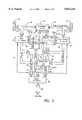
- FIG. 2is a block diagram of a preferred embodiment of a multiple interface input/output port 40 in accordance with the present invention, which is embodied as part of a peripheral device (not shown) having an internal interface bus 60.
- the multiple interface input/output port 40 of the present inventioncomprises a connector 42 (analogous to connector 20 of FIG. 1) that is adapted to connect to an interface bus or port (not shown) on a host computer (not shown).
- the connector 42comprises a 25-pin DB connector, however, in other embodiments, the connector may comprise a 36-pin Centronics, 36-pin High Density, 50-pin Centronics or 50-pin High Density connector.
- an intermediate bus 44 of the multiple interface input/output port 40serves as an extension of the host interface bus.
- the internal interface bus 60 of the peripheral deviceis a SCSI-2 bus.
- the multiple interface input/output port 40 of the preferred embodimentis designed to enable communication between the SCSI-2 bus 60 of the peripheral device and either another SCSI-2 bus on the host computer, or a different type of bus such as, for example, the standard unidirectional or bi-directional parallel port bus, the extended parallel port bus (EPP) or the enhanced capability port (ECP).
- EPPextended parallel port bus
- ECPenhanced capability port
- An interface bus detection and control circuit 46is coupled to selected lines 45 of the intermediate bus 44 for automatically detecting the type of interface bus to which it is connected on the host computer. Based on this determination, the interface bus detection and control circuit 46 provides "mode” and “enable” signals on lines 48 for purposes described hereinafter.
- a SCSI-to-SCSI repeater circuit 54 and a parallel port-to-SCSI (PP-SCSI) interface adapter 56are each coupled in parallel between the intermediate bus 44 and the interface bus 60 of the peripheral device via respective I/O control blocks 50 and 58.
- the SCSI-to-SCSI repeater circuit 54serves to redrive signals transmitted between the interface bus 60 of the peripheral device and the interface bus of the host computer when both interface buses are of the same type (i.e., SCSI-2).
- the PP-SCSI interface adapter 56provides physical and logical protocol translation between the host interface bus and the interface bus 60 of the peripheral device when the host interface bus is of a different type than the SCSI-2 bus 60 of the peripheral device.
- the peripheral devicecan continue to transmit and receive SCSI commands over its interface bus 60 in accordance with the SCSI-2 protocol, while the PP-SCSI interface adapter 56 provides the necessary physical and logical protocol translation to transmit and receive those commands to and from the detected parallel port interface bus of the host computer via intermediate bus 44 and connector 42.
- the interface bus detection circuit 46 of the present embodimentdetermines whether the connector 42 is connected to a SCSI bus or a parallel port bus on the host computer, the interface bus detection circuit 46 provides "mode” and “enable” signals on lines 48 in order to enable either the SCSI-SCSI repeater circuit 54 or the PP-SCSI interface adapter 56, as appropriate.
- a particular one of the two adapters 54, 56is enabled by routing communications through that adapter via the Host and Device I/O control blocks 50 and 58.
- the Host and Device I/O control blocks 50, 58are controlled by the "mode” and “enable” signals provided on lines 48 by the interface bus detection and control block 46. In the present embodiment, it is primarily the "mode” signal that determines whether communications are routed through the SCSI-to-SCSI repeater circuit 54 or the PP-SCSI interface adapter 56.
- the SCSI-to-SCSI repeater circuit 54 and the PP-to-SCSI interface adapter 56do not themselves receive "enabling" signals from the interface bus detection and control circuit 46. Rather, as described above, one of the two circuits 54, 56 is enabled by routing communications through that circuit via the Host and Device I/O control blocks 50 and 58.
- FIG. 1illustrates an alternative possibility where the respective interface adapters (and/or repeater circuit) 26, 28, 30 receive respective enabling signals from the interface bus detection circuit 22 via lines 32, 34 and 36.
- the terms "enable” and "enabling"are intended to encompass all such possibilities.
- the connector 42comprises a 25 pin DSUB connector having 25 pins numbered consecutively
- the intermediate bus 44likewise comprises 25 lines each coupled to a respective one of the pins of the connector 42.
- Table 1illustrates how the 25 pins of the connector 42 and corresponding 25 lines of the intermediate bus 44 are defined, in accordance with the present invention, for both SCSI-2 and parallel port connections.
- Line 25carries termination power when the host interface bus is a SCSI bus, such as a SCSI-2 bus.
- a data transmission cablecan be employed to connect the 25-pin DB connector 42 of the multiple interface input/output port 40 to a corresponding connector of the interface bus (SCSI or parallel port) of the host computer.
- the mating connector on the host computeris also a 25-pin DB connector (either SCSI or parallel port)
- connection between the connector 42 and the particular interface port on the host computeris preferably made using an interchangeable SCSI/Parallel Port cable, such as that claimed and described in co-pending application Ser. No. 08/439,776, filed May 12, 1995, and entitled "Combined SCSI/Parallel Port Cable".
- lines 1-17 and 19-23(twenty-two lines total) of the intermediate bus 44 are provided to the Host I/O control block 50.
- the Host I/O Control block 50provides these lines to the SCSI-to-SCSI repeater circuit 54 and to the PP-SCSI interface adapter 56, respectively, via an internal HostIN bus 52. (Note: the bus widths are indicated in FIG.
- Lines 18 and 24 of the intermediate bus 44are grounded, and line 25 (not shown) is used to carry termination power from the host computer when the interface bus of the host computer to which the peripheral is connected is of the same type as the internal bus 60 of the peripheral, i.e., a SCSI-2 bus.
- Line 25provides a ground when the host interface bus of the host computer is a parallel port bus.
- the interface bus 60 of the peripheral devicecomprises eighteen signal lines that correspond to lines 1-6, 8, 10-13, 15, 17 and 19-23 of the intermediate bus 44.
- SCSI signals to be transmitted from the peripheral device to the host computerare provided by the Device I/O Control block 58 to the SCSI-SCSI repeater circuit 54 and the PP-SCSI interface adapter 56, via an internal DeviceIN bus 64.
- the SCSI-to-SCSI repeater circuit 54redrives signals received on lines 1-6, 8, 10-13, 15, 17 and 19-23 of the HostIN bus 52 and provides these redriven signals to the Device I/O Control block via an internal SCSI-SCSI OUT bus 62. Lines 7, 9, 14 and 16 of the HostIN bus 52 are ignored in the SCSI-SCSI repeater circuit and are not provided to the input of the Device I/O Control block 58.
- Signals received by the SCSI-SCSI repeater circuit 54 from the Device I/O Control block 58 via the DeviceIN bus 64are likewise redriven and provided to an input of the Host I/O Control block 50 via corresponding lines 1-6, 8, 10-13, 15, 17 and 19-23 of a twenty-two line internal SCSI-Host OUT bus 70. Lines 7, 9, 14 and 16 of the SCSI-Host OUT bus 70 are grounded.
- the PP-to-SCSI interface adapter 56receives signals transmitted from the host computer via the HostIN bus 52 and, when the interface bus of the host computer is a parallel port bus, provides both logical and physical translation of signals received on the HostIN bus 52 in a parallel port format into appropriate SCSI-2 signals that are then provided via an eighteen line internal PP-SCSI OUT bus 66 to an input of the Device I/O Control block 58.
- SCSI-2 signals received by the PP-SCSI interface adapter 56 from the Device I/O Control block 58 via the DeviceIN bus 64are translated from their SCSI-2 format into appropriate parallel port signals which are then output to the Host I/O Control block 50 via a twenty-two line internal PP-HostOUT Bus 68.
- the twenty-two lines of the PP-HostOUT bus 68correspond to lines 1-17 and 19-23 of the intermediate bus 44.
- the PP-SCSI interface adapter 56provides a "PP enable" signal on line 49.
- the interface bus detection and control block 46provides "mode” and “enable” signals depending on whether the host interface bus is determined to be a parallel port bus or a SCSI bus, such as a SCSI-2 bus.
- the "mode” and “enable” signalscause the Device I/O Control block 58 to route signals on the SCSI-SCSI OUT bus 62 to the interface bus 60 of the peripheral device.
- the Device I/O Control block 58disables the PP-SCSI OUT bus 66 in this case.
- the "mode" and “enable” signalscause the Host I/O Control block 50 to receive signals from the repeater circuit 54 via the SCSI-HostOUT bus 70 and to route those signals to the intermediate bus 44 while disabling the PP-HostOUT bus 68.
- communications between the interface buses of the host computer and peripheral deviceare effectively routed through the SCSI-SCSI repeater circuit 54 via the respective I/O Control blocks 50, 58.
- the "mode” and “enable” signalscause the Device I/O Control block 58 to route signals transmitted on the PP-SCSI OUT bus 66 to the interface bus 60 of the device, while disabling the SCSI-SCSI OUT bus 62.
- the "mode” and “enable” signalscause the Host I/O Control block 50 to receive signals from the interface adapter 56 via the PP-HostOUT bus 68 and to route those signals to the intermediate bus 44 while disabling the SCSI-HostOUT bus 70. In this case, therefore, communications between the interface buses of the host computer and the peripheral device are effectively routed through the PP-SCSI interface adapter 56 via the respective I/O Control blocks 50, 58 in order to provide the necessary interface translation.
- the multiple interface input/output port 40further comprises a pass-through bus 72 that allows a third device (not shown) to be connected to the host computer through the multiple interface input/output port 40.
- a second connector 73is coupled to the pass-through bus 72 to facilitate connection of the third device to the pass-through bus 72.
- Selected lines 75 of the pass-through bus 72are provided to the interface bus detection and control block 46 which, in addition to detecting the type of the interface bus of the host computer, also detects the type of the interface bus of the third device.
- the pass-through bus 72is enabled only when the interface bus of the third device is of the same type as the interface bus of the host computer.
- a Pass-through I/O Control block 74controls access to the pass-through bus 72 in response to the aforementioned "mode" signal from the interface bus detection and control block 46, as well as an additional "PT enable" signal described hereinafter.
- lines 1-17 and 19-23 (twenty-two lines total) of the pass-through bus 72are provided to the Pass-through I/O Control block 74.
- the Pass-through I/O Control block 50routes these lines to the SCSI-to-SCSI repeater circuit 54 and to the PP-SCSI interface adapter 56 via an internal Pass-throughIN bus 76.
- Lines 18 and 24 of the pass-through bus 72are grounded.
- Line 25 of the pass-through busis controlled by the interface bus detection and control circuit 46, as described hereinafter.
- the interface bus of the host computer and the interface bus of a third device connected to the pass-through bus 72are both SCSI buses, e.g., SCSI-2 buses
- SCSI signals received on the HostIN bus 52 from the host computerwill be redriven by the SCSI-to-SCSI repeater circuit 54 and provided to the Pass-through I/O Control block 74 via an internal SCSI-PT OUT bus 80.
- the "mode” and "PT enable" signals from the interface bus detection and control block 46cause the Pass-through I/O Control block 74 to route the signals on the SCSI-PT OUT bus 80 to the pass-through bus 72 for communication with the third device.
- SCSI signals imposed on the Pass-throughIN bus 72 from the third devicewill be redriven on the SCSI-Host Out bus 70 for communication via the Host I/O Control block 50 to the host computer.
- redriving of SCSI signals between the intermediate bus 44 and the pass-through bus 72occurs in conjunction with the redriving of signals between the intermediate bus 44 and the interface bus 60 of the peripheral device.
- the SCSI-SCSI repeater circuit 54is a three-way redriving circuit that allows the first bus signal asserted on the HostIN, DeviceIN or Pass-throughIN buses 52, 64, 76 to control the output buses (SCSI-HostOUT 70, SCSI-SCSI OUT 62, SCSI-PT OUT 80) corresponding to the other two input buses. All of the devices therefore appear connected to a single, continuous SCSI bus.
- the PP-SCSI interface adapter 56When communication with the peripheral device is desired, the PP-SCSI interface adapter 56 is instructed to translate parallel port signals received on the Host IN bus 52 into appropriate SCSI-2 signals and to route those signals to the Device I/O Control block 58 via the PP-SCSI OUT bus 66. On the other hand, when communication with the third device attached to the pass-through bus 72 is desired, the PP-SCSI interface adapter 56 is instructed to simply allow any parallel port data received on the HostIN bus 52 to pass through the PP-SCSI interface adapter 56, without translation, to the PP-PT OUT bus 78.
- FIG. 3is a block diagram illustrating further details of the interface bus detection and control block 46 in accordance with the preferred embodiment of the present invention.
- the interface bus detection and control block 46comprises a first interface bus detection circuit 82a which receives, as inputs thereto, lines 14, 16, 19 and 25 of the intermediate bus 44. As described hereinafter, the first interface bus detection circuit 82a compares signal levels on those lines to a reference potential to determine whether the interface bus of the host computer is a SCSI bus or a parallel port bus.
- the first interface bus detection circuit 82aWhen a SCSI bus is detected, the first interface bus detection circuit 82a provides an active-low (i.e., logic-0) signal on line 92. Conversely, when a parallel port bus is detected, the first interface bus detection circuit 82a provides an active-low signal on line 94. When neither a parallel port bus nor a SCSI bus is detected, lines 92 and 94 remain high (i.e., logic-1).
- An “enable” signalis provided on line 48a by an exclusive-OR gate 95 that receives the signals on lines 92 and 94 at inverted inputs thereof.
- the "enable” signalenables the output drivers of the Host and Device I/O Control blocks 50, 58 when a valid interface bus (i.e., SCSI or parallel port) is detected on the intermediate (host) bus 44.
- the enable signalis an active-high signal. If neither type of bus is detected, or if for some reason the interface bus detection circuit 82a provides a logic-0 signal on both lines 92 and 94, the exclusive-OR gate 95 ensures that the enable signal will not be asserted (i.e., line 48a will remain at logic-0). As further shown in FIG.
- the active-low output on line 92defines a "mode” signal that is provided to the respective I/O control blocks via line 48b.
- the "mode” signalcontrols the flow of data (either SCSI or parallel port) through the Host, Device and Pass-through I/O Control blocks 50, 58, 74.
- the "mode” signal on line 48bis low. Otherwise, the "mode” signal remains high.
- a second interface bus detection circuit 82breceives, as inputs thereto, lines 14, 16, 19 and 25 of the pass-through bus 72. Assuming a third device is connected to the pass-through bus, the second interface bus detection circuit 82b compares signal levels on lines 14, 16, 19 and 25 to a reference potential to determine whether the interface bus of the third device is a SCSI bus or a parallel port bus. When a SCSI bus is detected, the second interface bus detection circuit 82b provides an active-low (i.e., logic-0) signal on line 96. Conversely, when a parallel port bus is detected, the second interface bus detection circuit 82b provides an active-low signal on line 98. When neither a parallel port bus nor a SCSI bus is detected, lines 96 and 98 remain high (i.e., logic-1).
- An active-high "PT enable" signalis provided on line 48c to enable the output drivers of the Pass-through bus 72 whenever the interface buses of the host computer and third device are either both SCSI buses or both parallel port buses.
- the pass-through bus 72is only enabled when the interface bus of the host computer is of the same type as the interface bus of the device attached to the pass-through bus 72. This simplifies the implementation of the pass-through bus 72 because no protocol translation is necessary.
- the "PT enable" signalis generated by logic gates 100, 106 and 108.
- Lines 92 and 96are input to gate 100 (an OR function) which provides an active-low output (i.e., logic-0) whenever lines 92 and 96 are both at logic-0, indicating that the interface buses of the host computer and third device are both SCSI buses.
- Line 94 and 98are input to gate 106 which provides an active-low output (i.e., logic-0) whenever lines 94 and 98 are both at logic-0, indicating that the interface buses of the host computer and third device are both parallel port buses.
- the outputs of gates 100 and 106are fed to inverted inputs of gate 108.
- the "PT enable" line 48cis asserted (i.e., logic-1) whenever the interface buses of the host computer and third device are either both SCSI buses or both parallel port buses.
- two additional gates 102 and 104are provided for future implementations in which the multiple-protocol input/output circuit 40 is adapted to handle cases in which the host interface bus and the interface bus of a third device connected to the pass-through bus are of different types.
- the output of gate 102will be asserted (i.e., logic-0) when the interface bus of the host computer is a parallel port bus, but the pass-through device has a SCSI interface bus.
- the output of gate 104will be asserted (i.e., logic-0) when the host interface bus is a SCSI bus, but the pass-through device has a parallel port bus.
- the multiple interface input/output port 40can be configured to handle such mixed modes by adding an additional parallel port-to-SCSI interface adapter between the intermediate (host) and pass-through buses 44, 72 in order to provide the necessary protocol translation between the host computer and pass-through devices in such cases.
- line 25is coupled to a +5V power supply via diode 88 and transistor 86 in order to provide termination power to the pass-through device.
- a self-resetting fuse 87is provided to protect the pass-through device, if necessary.
- line 25is grounded through transistor 90.
- FIG. 4is a block diagram showing further details of the Host I/O control block 50.
- FIG. 4illustrates the two-way routing of signals between each of the twenty-two lines (1-17 and 19-23) of the intermediate (host) bus 44 and the respective lines, of the HostIN, PP-Host OUT and SCSI-Host OUT buses 52, 68, 70.
- signals transmitted from the Host computerare allowed to flow freely from each of lines 1-17 and 19-23 of the intermediate bus 44 to the HostIN bus 52 through the input 207 of a respective bi-directional line driver 206.
- Each line of the intermediate bus 44is coupled to a +5V source through a pull-up resistor 203.
- the "enable" and "mode” signalsare received on lines 48a and 48b from the interface bus detection and control block 46. These signals control first and second multiplexers 200,202 and an AND gate 204 for each line 1-17 and 19-23 of the intermediate bus 44.
- the "mode" signalis at logic-0 and the "0" input of each multiplexer 200, 202 is selected.
- Active high signalsare provided by the SCSI-SCSI repeater circuit 54 on each line of the SCSI-Host OUT bus 70.
- one of the lines of the SCSI-Host OUT bus 70is asserted (i.e., logic-1)
- the output 208 of the respective bi-directional line driver 206is enabled via line 205, and the corresponding line of the intermediate bus 44 is therefore pulled to ground through the "0" input of the respective multiplexer 202 on that line.
- the active high signals on the SCSI-Host OUT bus 70are converted by the Host I/O control block 50 into active low SCSI signals on the intermediate bus 44.
- the "mode" signalis at logic-1 and the other input of each multiplexer 200, 202 is selected. Also, in this mode, the PP-SCSI interface adapter 58 provides a "PP enable" signal (logic-1) on line 49. For each line of the intermediate bus 44, the "PP enable" signal is routed through the respective multiplexer 200 and gate 204 to enable the output 208 of the respective line driver 206 for that line. Each line of the intermediate bus 44 can then be driven by the PP-Host OUT bus 68 through the "1" input of its respective multiplexer 202.
- terminationis provided on selected lines of the intermediate bus 44 in SCSI mode.
- SCSI terminationis provided only on lines 1-6, 8, 10-13, 15, 17 and 19-23.
- FIG. 5is a block diagram showing further details of the Pass-through I/O control block 74.
- FIG. 5illustrates the two-way routing of signals between each of the twenty-two lines (1-17 and 19-23) of the pass-through bus 72 and the respective lines of the Pass-throughIN, PP-PT OUT and SCSI-PT OUT buses 76, 78, 80.
- signals transmitted from a third device connected to the pass-through busare allowed to flow freely from each line (1-17 and 19-23) of the pass-through bus 72 to the Pass-through IN bus 76 through the input 207' of a respective bi-directional line driver 206'.
- Each line of the pass-through bus 72is coupled to a +5V source through a pull-up resistor 203'.
- the Pass-through I/O Control block 74receives the "PT enable" signal on line 48c from the interface bus detection and control circuit 46, rather than the "enable” signal that the Host and Device I/O Control blocks 50, 58 receive.
- the "mode” signalis received on line 48b.
- These signalscontrol first and second multiplexers 200', 202' and an AND gate 204' for each line (1-17 and 19-23) of the pass-through bus 72.
- the Pass-through I/O Control block 74functions similarly to the Host I/O Control block 50.
- the "mode" signalis at logic-0 and the "0" input of each multiplexer 200', 202' is selected.
- Active high signalsare provided by the SCSI-SCSI repeater circuit 54 on each line of the SCSI-PT OUT bus 80.
- one of the lines of the SCSI-PT OUT bus 80is asserted (i.e., logic-1)
- the output 208' of the respective bi-directional line driver 206'is enabled via line 205', and the corresponding line of the pass-through bus 72 is pulled to ground through the "0" input of the respective multiplexer 202' on that line.
- the active-high signals on the SCSI-PT OUT bus 80are converted by the Pass-through I/O Control block 74 into active-low SCSI signals on the pass-through bus 72.
- the "mode" signalis at logic-1 and the other input of each multiplexer 200', 202' is selected. Also, as mentioned above, the PP-SCSI interface adapter 58 provides a "PP enable" signal (logic-1) on line 49 in this mode. For each line of the pass-through bus 72, the "PP enable" signal is routed through the respective multiplexer 200' and gate 204' to enable the output 208' of the respective line driver 206' for that line. Each line (1-17 and 19-23) of the pass-through bus 72 can then be driven by the PP-PT OUT bus 78 through the "1" input of its respective multiplexer 202'.
- terminationis provided on selected lines of the pass-through bus 72 in SCSI mode.
- SCSI terminationis provided only on lines 1-6, 8, 10-13, 15, 17 and 19-23 of the pass-through bus 72.
- FIG. 6is a block diagram showing further details of the Device I/O Control block 58.
- FIG. 6illustrates the two-way routing of signals between each of the eighteen lines of the interface bus 60 of the peripheral device and the respective lines of the DeviceIN, SCSI-SCSI OUT and PP-SCSI OUT buses 64, 62, 66, respectively.
- signals asserted by the peripheral device on its interface bus 60are allowed to flow freely from each line of the interface bus 60 to the DeviceIN bus 64 through the input 207" of a respective bi-directional line driver 206".
- the other input 208" of each bi-directional line driver 206"is coupled to ground.
- Each line of the peripheral interface bus 60is coupled to a +5V source through a pull-up resistor 203".
- the Device I/O Control block 58receives the "enable” and "mode” signals on lines 48a and 48b, respectively, from the interface bus detection and control block 46. These signals control a multiplexer 210 and an AND gate 204" for each line (1-18) of the peripheral interface bus 60.
- the "mode" signalis at logic-0 and the "0" input of the multiplexer 210 on each line of the interface bus 60 is selected.
- the SCSI-SCSI repeater circuit 54provides active high signals on each line of the SCSI-SCSI OUT bus 62.
- one of the lines of the SCSI-SCSI OUT bus 62is asserted (i.e., logic-1)
- the output 208" of the respective bi-directional line driver 206"is enabled via line 205", and the corresponding line of the peripheral interface bus 60 is therefore pulled to ground via the grounded input 208" of the line driver 206".
- the active high signals on the SCSI-SCSI OUT bus 62are converted by the Device I/O Control block 58 into active low SCSI signals on the interface bus 60 of the peripheral device.
- the "mode" signalis at logic-1 and the other input of each multiplexer 210 is selected.
- the PP-SCSI interface adapter 56provides active high signals on each line of the PP-SCSI OUT bus 66.
- one of the lines of the PP-SCSI OUT bus 66is asserted (i.e., logic-1)
- the output 208" of the respective bi-directional line driver 206"is enabled via line 205", and the corresponding line of the peripheral interface bus 60 is therefore pulled to ground via the grounded input 208" of the line driver 206".
- the active high signals on the PP-SCSI OUT bus 66are also converted by the Device I/O Control block 58 into active low signals on the interface bus 60 of the peripheral device. No termination is provided on the interface bus 60 of the peripheral device.
- the Host, Device and Pass-through I/O Control blocks 50, 58, 74respond to the "mode", "enable” and "PT enable” signals in order to route communications between the host computer, the peripheral device and a third device through either the SCSI-SCSI repeater circuit 54 or the PP-SCSI interface adapter 56 depending on the detected interfaces of the host and pass-through devices.
- interface busescomprise a plurality of lines, some of which may be defined to carry data and control signals, and others of which may carry a system ground.
- a particular type of interface buse.g., SCSI, parallel port, etc.
- SCSISerial Bus
- parallel porte.g., a particular type of interface bus
- predetermined ones of the lines of the interface busbeing grounded.
- different linesare grounded on different types of interface buses. For example, lines 14 and 16 of a SCSI bus are grounded, whereas a parallel port bus has either line 25 grounded, or line 19 grounded and at least one of lines 14 and 16 not grounded.
- a method of detecting a particular type of interface bus from a plurality of different known types of interface busescomprises the steps of comparing signal levels on selected ones of the lines of an interface bus under consideration to a reference potential to determine which of the selected lines of the interface are grounded, and then indicating the type (e.g., SCSI, parallel port, etc.) of the interface bus based on the determination of which lines are grounded.
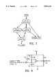
- FIG. 7is a state diagram illustrating a preferred embodiment of the method of the present invention. The method illustrated in FIG. 4 is capable of detecting whether an interface bus is either a SCSI bus or a parallel port bus.
- the interface bus under consideration(e.g., intermediate (host) bus 44 or pass-through bus 72) is assumed to comprise twenty-five lines numbered consecutively, each line being defined as indicated in Table 1 depending on whether the interface bus is a SCSI bus or a parallel port bus.
- the methodcomprises the steps of comparing voltage levels on each of lines 14, 16, 19 and 25, and then indicating the type of the interface bus based on the determination of which lines are grounded.
- an indication that the interface bus under consideration is a parallel port protocolis made when either (i) line (i.e., connector pin) 25 is grounded or (ii) line 19 is grounded and at least one of lines 14 and 16 is not grounded.
- An indication that the interface bus is a SCSI busis made when line 25 is determined not to be grounded, but lines 14 and 16 are determined to be grounded. A state in which lines 25 and 19 are not grounded and at least one of lines 14 and 16 is not grounded is undefined. It is understood that the method of the present invention is not limited to detecting parallel port and SCSI buses, but may be employed to distinguish between any number of different interface buses so long as each interface bus is characterized by a unique pattern of grounded lines. Moreover, the preferred embodiment is not limited to use in connection with SCSI and/or parallel port interface buses of twenty five lines.
- the methodmay be employed to detect a SCSI or parallel port bus on any one of the standard bus sizes typically employed in accordance with these interfaces. Also, other lines of the SCSI and parallel port bus structures may be examined to determine whether a particular interface bus is a SCSI bus or a parallel port interface bus, and the present invention is by no means limited to use of lines 14, 16, 19 and 25 in this regard.
- An alternate method of detecting whether an interface bus is a SCSI bus or a parallel port buscomprises the steps of comparing a voltage level on line 25 to a reference potential to determine only whether line 25 is grounded. An indication that the interface bus is a SCSI bus is made if line 25 is determined not to be grounded. An indication that the interface bus is a parallel port bus is made if line 25 is determined to be grounded.
- An interface bus detection circuit in accordance with the present inventionwhich may be used to implement interface bus detection circuits 82a and 82b of FIG. 3, comprises means for comparing signal levels on selected ones of the lines of an interface bus to a reference potential to determine which of the selected lines is grounded, and means for indicating the type of the interface bus based on the determination of which lines are grounded.
- FIG. 8is a schematic diagram of one embodiment of an interface bus detection circuit in accordance with the present invention.
- the interface bus detection circuit of FIG. 8implements the alternate method described above.
- the circuitcomprises a single open-collector voltage comparator U1.
- the non-inverting input (“+") of the comparator U1is connected directly to line 25 of the interface bus.
- Line 25is coupled to a +5V source through pull-up resistor 124 to ensure that signal integrity to the remainder of the multiple interface input/output port 40 is not lost.
- the inverting input (“-") of the comparator U1is biased with a reference voltage.
- the reference voltageis determined by a pair of resistors 126, 130 that form a voltage divider.
- resistor 126comprises a 4.75 k ⁇ resistor
- resistor 130comprises a 250 ⁇ resistor. Consequently, the reference voltage appearing at the inverting input ("-") of the comparator U1 is slightly above 0 volts.
- the output 128 of the comparatoris low indicating that the interface bus is not a SCSI bus; it is assumed in this case that the interface bus is therefore a parallel port bus.
- line 25is not grounded, which is the case with a SCSI bus, e.g., SCSI-2
- the voltage level at the non-inverting input ("+") of the comparator U1will exceed the reference voltage at the inverting input ("-"). Consequently, the output 128 of the comparator U1 will be high indicating that a SCSI bus has been detected.
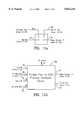
- FIG. 9is a schematic diagram illustrating both a circuit for carrying out the method of FIG. 7 and another embodiment of an interface bus detection circuit in accordance with the present invention.
- the means for comparing signal levels on selected ones of the lines of an interface bus under consideration to a reference potentialcomprises four open collector voltage comparators U1, U2, U3 and U4, coupled respectively to lines 25, 16, 14 and 19.
- Each comparator U1, U2, U3, U4compares its respective line of the interface bus to a reference potential determined by resistors 138 and 140 which form a voltage divider.
- the reference voltagewhich in the present embodiment is slightly above 0 volts, is applied to the inverting input "-" of comparator U1, and the non-inverting inputs "+" of comparators U2, U3 and U4.
- each comparator U1, U2, U3, U4is tied directly to its respective line of the interface bus.
- line 25When line 25 is grounded, the output of comparator U1 will be low (i.e., ⁇ 0 volts).
- lines 14, 16 or 19When lines 14, 16 or 19 are grounded, the output of their respective comparators U3, U2, U4 will be high (i.e., ⁇ 5 volts).
- the interface bus detection circuit of the present inventionis intended to perform a monitoring function only; the circuit should not interfere with the signal on any of the lines of the interface bus. Accordingly, in the present embodiment, lines 14, 16, 19 and 25 of the interface bus are coupled to a +5V source through respective pull-up resistors 134, 132, 136 and 130. The pull-up resistors 130-136 ensure that signal integrity on each line is not lost.
- Transistors Q1, Q2, Q3 and respective biasing resistors 144-162comprise a means for indicating whether the interface bus is a SCSI type or a parallel port type based on the outputs of the respective comparators U1, U2, U3 and U4.
- a SCSI busis indicated when transistor Q1 is turned on (i.e., line 92 or 96 goes low), and a parallel port bus is indicated when either Q3 is turned on or the output of comparator U1 is low (i.e., line 94 or 98 goes low).
- Transistor Q1turns on when the outputs of comparators U2 and U3 are both high (i.e., lines 14 and 16 are grounded).
- Transistor Q3turns on when the output of comparator U4 goes high (i.e., line 19 is grounded) and either comparator U2 or comparator U3 is low (i.e., either of lines 14 and 16 is not grounded).
- the interface bus detection circuit of FIG. 9indicates that the interface bus is a SCSI bus when lines 14 and 16 are both grounded, and indicates that the interface bus is a parallel port bus when either (i) line 25 is grounded, or (ii) line 19 is grounded but at least one of lines 14 and 16 is not grounded.
- FIG. 9is a schematic diagram illustrating an alternative circuit for carrying out the method of FIG. 7, as well as yet another embodiment of an interface bus detection circuit in accordance with the present invention.
- the means for comparing signal levels on selected ones of the lines of the interface bus under consideration to a reference potentialcomprises four open collector voltage comparators U1, U2, U3 and U4, coupled respectively to lines 25, 16, 14 and 19.
- Each comparator U1, U2, U3, U4compares its respective line of the interface bus to a reference potential determined by resistors 172 and 174 which form a voltage divider.
- the reference voltagewhich again approaches 0 volts, is applied to the non-inverting input "+" of each comparator U1, U2, U3 and U4.
- the other input "-" of each comparator U1, U2, U3, U4is tied directly to its respective line of the interface bus.
- each comparator U1, U2, U3, U4are coupled to the +5V source through respective pull-up resistors 176-182.
- the output of its respective comparator U3, U2, U4, U1goes high (i.e., logic-1). Otherwise, the outputs of each comparator are low (i.e., logic-0).
- the interface bus detection circuit of the present inventionperforms a monitoring function only, and the circuit should not interfere with the signal on any of the lines of the interface bus. Accordingly, in the present embodiment, lines 14, 16, 19 and 25 of the interface bus are coupled to a +5V source through respective pull-up resistors 168, 166, 170 and 164. The pull-up resistors 164-170 ensure that signal integrity on each line is not lost.
- Logic gates U5-U12comprise a means for indicating whether the interface bus is a SCSI bus or a parallel port bus based on the outputs of the respective comparators U1, U2, U3 and U4.
- a SCSI busis indicated when NAND gate U11 receives a logic-1 at both inputs.
- a parallel port busis indicated when NAND gate U12 receives a logic-1 at both inputs.
- Exclusive-OR gate U10prevents both inputs of U11 and U12 from going high at the same time.
- the outputs of logic gates U6 and U9drive the inputs of gates U11 and U12, respectively.
- AND gate U11will receives a logic-1 at both inputs when the output of AND gate U6 is high; AND gate U12 will receive a logic-1 at both inputs when the output of OR gate U9 is high.
- AND gate U6outputs a logic-1 when the outputs of comparators U2 and U3 are high, and the output of comparator U1 is low (i.e., lines 14 and 16 are grounded, but line 25 is not grounded).
- OR gate U9outputs a logic 1 when either (i) the output of comparator U1 is high (i.e., line 25 is grounded) or (ii) the output of comparator U4 is high, and at least one of the outputs of comparators U2 and U3 is low (i.e., line 19 is grounded, and at least one of lines 14 and 16 is not grounded).
- interface bus 9indicates that the interface bus is a SCSI bus when lines 14 and 16 are both grounded, and indicates that the interface bus is a parallel port bus when either (i) line 25 is grounded, or (ii) line 19 is grounded but at least one of lines 14 and 16 is not grounded.
- the first and second interface bus detection circuits 82a and 82b of the interface bus detection and control block 46 illustrated in FIG. 3are each implemented using one of the interface bus detection circuits illustrated in FIGS. 9 and 10.
- the interface bus detection circuit of FIG. 9provides an analog solution
- the interface bus detection circuit of FIG. 10provides a digital solution. While the circuits of FIGS. 9 and 10 are preferred, either one of the interface bus detection circuits 82a, 82b could be implemented using the interface bus detection circuit of FIG. 8.
- interface bus detection circuits of FIGS. 8-10are not limited to the detection of parallel port and SCSI buses, but may be employed to distinguish between any number of different types of interface bus so long as each different type of interface bus is characterized by a unique pattern of grounded lines.
- the preferred embodimentis not limited to use in connection with SCSI and/or parallel port interface buses of twenty five lines, or pins. Rather, the method may be employed in connection with any one of the standard bus sizes typically employed in accordance with these interface protocols.
- FIGS. 11(a) and 11(b)illustrate further details of the PP-SCSI interface adapter 56 of FIG. 2 in accordance with the preferred embodiment of the present invention.
- lines 19-23 of the PP-Host OUT and PP-PT OUT buses 68 and 78are tied low.
- these grounded lines of the PP-Host OUT and PP-PT OUT buses 68, 78feed the respective output drivers of the Host and Pass-through I/O Control blocks 50 and 74, respectively.
- FIG. 11(a)illustrate further details of the PP-SCSI interface adapter 56 of FIG. 2 in accordance with the preferred embodiment of the present invention.
- lines 19-23 of the PP-Host OUT and PP-PT OUT buses 68 and 78are tied low.
- these grounded lines of the PP-Host OUT and PP-PT OUT buses 68, 78feed the respective output drivers of the Host and Pass-through I/O Control blocks 50 and 74, respectively.
- lines 19-23 of the HostIN and Pass-throughIN buses 52, 76are open-circuited in the PP-SCSI interface adapter 56 since they are defined as grounds in accordance with the parallel port protocols and therefore do not carry any information that requires translation.
- Lines 1-17 of the HostIN and Pass-throughIN buses 52, 76are provided as inputs to a parallel port-to-SCSI adapter circuit 56a.
- Lines 1-17 of the PP-Host OUT and PP-PT OUT busesare connected to respective outputs of the adapter circuit 56a.
- the eighteen lines of the DeviceIN and PP-SCSI OUT buses 64, 66, which correspond to lines 1-6, 8, 10-13, 15, 17 and 19-23 of the intermediate and pass-through buses 44, 72,are also connected to respective inputs and outputs of the adapter circuit 56a.
- a commandcan be issued from the host computer to the PP-to-SCSI adapter circuit 56a, via the HostIN bus 52, instructing the adapter circuit 56a either to provide the necessary physical and logical protocol translation to enable communication between the host interface bus and the peripheral interface bus 60, or (ii) to pass parallel port data from the host computer through the PP-SCSI interface adapter 56, without translation, to the pass-through bus 72 when communication with a third device connected to the pass-through bus 72 is desired.
- the PP-SCSI protocol adapter circuit 56amay be implemented using any one of a variety of commercially available parallel port-to-SCSI adapter solutions.
- the PP-SCSI adapter circuit 56amay be implemented using the discrete components employed in the Iomega PPA-3 parallel port-to-SCSI adapter available from Iomega Corporation, 1821 West 4000 South, Roy, Utah 84067, assignee of the present invention.
- the PP-SCSI interface adapter circuit 56acan be implemented using the EPSA-II chip available from Shuttle Technology, Inc., 43218 Christy Street, Fremont, Calif. 94538, or the RT90C20 chip from Rancho Technology, Inc., 10783 Bell Court, Collinso Cucamonga, Calif.
- a two chip solutioncan be implemented using any one of the following parallel port-to-ISA/IDE interface chips in conjunction with a standard ISA/IDE-to-SCSI interface chip, such as the 53C80 available from NCR Corporation, 1635 Aeroplaza Drive, Colorado Springs, Colo. 80916; the 50772B available from Microsolutions, 132 West Lincoln Highway, DeKalb, Ill. 60115, the SMC34C60 available from Standard Microsystems Corporation, 2107 North First Street, Suite 660, San Jose, Calif. 95131, and the CPX-FDI available from Shuttle Technology, Inc. Any of the aforementioned devices can be used to communicate SCSI commands to a SCSI device across a parallel port bus.
- the adapter circuitthen provides the necessary communication between itself and the interface bus (e.g. bus 60 of FIG. 2) of the peripheral device to which it is connected.
- the interface buse.g. bus 60 of FIG. 2
- modificationsmay be required to ensure proper interface to the Host, Device and Pass-through I/O Controllers 50, 58, 74.
- some of the aforementioned PP-SCSI adapter solutionsonly provide pass-through support for printer devices; that is, only a printer can be connected to the pass-through bus as a third device.
- parityis not provided on the intermediate and pass-through buses 44, 72 when the multiple interface input/output port 40 is in parallel port mode. Consequently, the PP-SCSI interface adapter must generate parity internally in order to provide parity to the peripheral interface bus 60.
- FIGS. 12(a) and 12(b)provide further details of the SCSI-to-SCSI repeater circuit 54 of FIG. 2.
- lines 7, 9, 14 and 16 of the SCSI-Host OUT and SCSI-PT OUT buses 70 and 80are tied high (+5V). This causes these lines to enable the respective line driver outputs 208, 208' in the Host and Pass-though I/O Control blocks 50, 74 when the multiple interface input/output port 40 is in the SCSI mode (See FIGS. 4 & 5).
- the corresponding lines 7, 9, 14 and 16 of the intermediate (host) bus 44 and the pass-through bus 72will be coupled to ground through the "0" inputs of their respective multiplexers 202 (See FIGS.
- lines 7, 9, 14 and 16 of the HostIN and Pass-throughIN buses 52, 76are open-circuited in the SCSI-SCSI repeater circuit 54 since they are defined as rounds in accordance with the SCSI-2 protocol and therefore do not carry any information content.
- the SCSI-to-SCSI repeater circuit 54allows undirected, bi-directional flow of signals between the interface bus of the host computer (i.e., intermediate bus 44), the peripheral interface bus 60, and the interface bus of a device connected to the pass-through bus 72 when each of the buses is a SCSI bus (e.g., SCSI-2). Essentially, the control and data lines of the SCSI bus, which would normally be wired straight through from device to device, are opened and buffered in the SCSI-SCSI repeater circuit 54.
- SCSI buse.g., SCSI-2
- the repeater circuit 54allows the first bus signal asserted on the HostIN, DeviceIN or Pass-throughIN buses 52, 64, 76 to control the output buses (SCSI-HostOUT 70, SCSI-SCSI OUT 62, SCSI-PT OUT 80) corresponding to the other two input buses. All of the devices therefore appear connected to a single, continuous SCSI bus, as is normally the case.
- FIG. 12(b)illustrates the three-way circuitry of the SCSI-SCSI repeater circuit 54 used to connect each of the eighteen data and control lines of the respective HostIN, DeviceIN and Pass-throughIN buses 52 to the respective lines of the SCSI-HostOUT, SCSI-SCSI OUT and SCSI-PT OUT buses 70, 62 and 80.
- the circuitry of FIG. 12(b)is repeated eighteen times in the SCSI-SCSI repeater circuit 54, once for each of the eighteen control and data lines.
- the three-way circuitry of FIG. 12(b)comprises nine logic gates, i.e., NOR gates U13, U15 and U17, XOR gates U14, U16 and U18, and three delay gates, or elements, 190a-c.
- NOR gates U13, U15 and U17monitor each of the three sources of incoming, active low signals on the respective lines of the HostIN, DeviceIN and Pass-throughIN buses 52, 64 and 76, respectively.
- XOR gates U14, U16 and U18drive the respective lines of the SCSI-Host OUT, SCSI-SCSI OUT and SCSI-PT OUT buses 70, 62 and 80.
- line 1 of each of the HostIN, DeviceIN and Pass-throughIN buses 52, 64 and 76would be connected to NOR gates U13, U15 and U17, respectively, in a first implementation of the three-way circuitry of FIG. 12(b).
- XOR gates U14, U16 and U18 of that first implementationwould each be connected to line 1 of the respective output bus 70, 62 or 80.
- a second implementation of the three-way circuitrywould be used to interconnect line 2 of each of the HostIN, DeviceIN and Pass-throughIN buses 52, 64, 76 to line 2 of each of the corresponding SCSI-Host OUT, SCSI-SCSI OUT and SCSI-PT OUT buses 70, 62 and 80, and so on.
- lines 1-6, 8, 10-13, 15, 17 and 19-23 of the HostIN and Pass-throughIN buses 52, 76correspond one-for-one to lines 1-18 of the DeviceIn bus 64. That is, lines 1-6 of the HostIN and Pass-throughIN buses 52, 76 correspond directly to lines 1-6 of the DeviceIN bus, line 8 of the HostIN and Pass-throughIN buses correspond to line 7 of the DeviceIN bus, lines 10-13 of the HostIN and Pass-throughIN buses correspond to lines 8-11 of the DeviceIN bus, and so on.
- the XOR gates U14, U16, U18provide active high signals on the SCSI-Host OUT, SCSI-SCSI Out and SCSI-PT OUT buses 70, 62, 80 which, in turn, enable the appropriate outputs in the Host, Device and Pass-through I/O Control blocks to effectively convert the active high signals into active low signals on the intermediate, peripheral and pass-through buses 44, 60 and 72.
- Delay gates 190a-cdelay the re-arming of the NOR gates to prevent latch ups.
- gates U13, U14 and 190awill now be described in detail, it being understood that the operation of gates U15, U16 and 190b and of gates U17, U18 and 190c is the same.
- all three inputs to NOR gates U13, U15 and U17are inactive, i.e., the corresponding lines of the HostIN, DeviceIN, and Pass-throughIN buses 52, 64, 76 are high (logic 1).
- the outputs of the NOR gates, the XOR gates U14, U16, U18 and all delay gates 190a-cwill be low (logic 0).
- NOR gate U13The output of NOR gate U13 is low since the HostIN line to which it is connected is high; the other four inputs to NOR gate U13 are low.
- the output of NOR gate U13will go high.
- the high output of NOR gate U13will, in turn, drive the corresponding lines of the SCSI-SCSI OUT and SCSI-PT OUT buses 62, 80 high via XOR gates U16 and U18.
- the active high outputs of XOR gates U16 and U18will, in turn, enable the appropriate output drivers in the Device and Pass-through I/O Control blocks 58, 74 to drive the corresponding lines of the peripheral and pass-through buses 60 and 72 low.
- the line asserted by the host computerwill be "redriven" through the SCSI-SCSI repeater circuit 54 on the peripheral and pass-through buses 60, 72.
- Delay gate 190amaintains a high output until the peripheral and pass-through buses 60, 72 and, consequently, the DeviceIN and Pass-through in buses 64, 76, are released (go high) by their associated drivers which, as explained above, are controlled by the outputs of XOR gates U16 and U18. It has been found that the delay of each delay gate 190a-c required for proper operation of the three-way circuitry is:
- t odis the delay time through the SCSI bus driver in the relevant Host, Device or Pass-through I/O Control block 50, 58, 74 (i.e., delay through AND gate 204 and buffer 208 in FIG. 4, 5 or 6);
- t busis the time from release of the relevant host (intermediate), peripheral or pass-through bus 44, 60, 72 until the voltage on that bus rises to 2.4 volts;
- t ris the delay time through the SCSI bus receiver in the relevant Host, Device or Pass-through I/O Control block 50, 58, 74 (i.e., delay through buffer 206 in FIG. 4, 5 or 6);
- t PLHis the propagation delay, low to high, through the relevant NOR gate U13, U15 or U17. As can be appreciated, these values may differ based on a number of factors and will depend on the particular implementation of each gate and buffer.
- the three-way circuitry of FIG. 12(b)operates in the same way for each line of the HostIN, DeviceIN and Pass-throughIN buses.
- the SCSI-SCSI repeater circuit 54allows the first device (i.e., Host, Peripheral or Pass-through) to assert a signal on either the HostIN, DeviceIN or Pass-throughIN bus 52, 64, 76 to control the output buses (SCSI-HostOUT 70, SCSI-SCSI OUT 62 or SCSI-PT OUT 80) corresponding to the other two input buses. All of the devices therefore appear connected to a single, continuous SCSI bus.
- the present inventionis directed to a multiple interface input/output port for a peripheral device that is capable of automatically detecting the type of interface bus to which it is connected in a host computer and then routing communications between the two devices through an appropriate interface adapter, if necessary, in a manner transparent to the user.
Landscapes
- Engineering & Computer Science (AREA)
- Theoretical Computer Science (AREA)
- General Engineering & Computer Science (AREA)
- Physics & Mathematics (AREA)
- General Physics & Mathematics (AREA)
- Computer Hardware Design (AREA)
- Bus Control (AREA)
Abstract
Description
TABLE 1 ______________________________________ SCSI and Parallel Port (PP) Definitions forIntermediate Bus 44 LINE # SCSI Function PP Function ______________________________________ 1REO nSTROBE 2 MSG D1 3 I/O D2 4RST D3 5ACK D4 6BSY D5 7GROUND D6 8DB0 D7 9GROUND D8 10DB3 nACK 11 DB5 BUSY 12DB6 ERROR 13DB7 SELECT 14 GROUND nAFEED 15 C/D nFAULT 16 GROUND nINIT 17 ATN nSELECT IN 18GROUND GROUND 19SEL GROUND 20DBP GROUND 21DB1 GROUND 22DB2 GROUND 23DB4 GROUND 24GROUND GROUND 25 TERM PWR GROUND ______________________________________
t.sub.od +t.sub.bus +t.sub.r +t.sub.PLH
Claims (33)
Priority Applications (6)
| Application Number | Priority Date | Filing Date | Title |
|---|---|---|---|
| US08/604,499US5832244A (en) | 1996-02-20 | 1996-02-20 | Multiple interface input/output port for a peripheral device |
| JP53015197AJP2001520771A (en) | 1996-02-20 | 1997-01-15 | Multi-interface I/O ports for peripheral devices |
| CA002243506ACA2243506A1 (en) | 1996-02-20 | 1997-01-15 | Multiple interface input/output port for a peripheral device |
| PCT/US1997/000850WO1997031386A1 (en) | 1996-02-20 | 1997-01-15 | Multiple interface input/output port for a peripheral device |
| EP97903011AEP0882304A4 (en) | 1996-02-20 | 1997-01-15 | Multiple interface input/output port for a peripheral device |
| US09/146,576US6073201A (en) | 1996-02-20 | 1998-09-03 | Multiple interface input/output port allows communication between the interface bus of the peripheral device and any one of the plurality of different types of interface buses |
Applications Claiming Priority (1)
| Application Number | Priority Date | Filing Date | Title |
|---|---|---|---|
| US08/604,499US5832244A (en) | 1996-02-20 | 1996-02-20 | Multiple interface input/output port for a peripheral device |
Related Child Applications (1)
| Application Number | Title | Priority Date | Filing Date |
|---|---|---|---|
| US09/146,576ContinuationUS6073201A (en) | 1996-02-20 | 1998-09-03 | Multiple interface input/output port allows communication between the interface bus of the peripheral device and any one of the plurality of different types of interface buses |
Publications (1)
| Publication Number | Publication Date |
|---|---|
| US5832244Atrue US5832244A (en) | 1998-11-03 |
Family
ID=24419846
Family Applications (2)
| Application Number | Title | Priority Date | Filing Date |
|---|---|---|---|
| US08/604,499Expired - LifetimeUS5832244A (en) | 1996-02-20 | 1996-02-20 | Multiple interface input/output port for a peripheral device |
| US09/146,576Expired - Fee RelatedUS6073201A (en) | 1996-02-20 | 1998-09-03 | Multiple interface input/output port allows communication between the interface bus of the peripheral device and any one of the plurality of different types of interface buses |
Family Applications After (1)
| Application Number | Title | Priority Date | Filing Date |
|---|---|---|---|
| US09/146,576Expired - Fee RelatedUS6073201A (en) | 1996-02-20 | 1998-09-03 | Multiple interface input/output port allows communication between the interface bus of the peripheral device and any one of the plurality of different types of interface buses |
Country Status (5)
| Country | Link |
|---|---|
| US (2) | US5832244A (en) |
| EP (1) | EP0882304A4 (en) |
| JP (1) | JP2001520771A (en) |
| CA (1) | CA2243506A1 (en) |
| WO (1) | WO1997031386A1 (en) |
Cited By (104)
| Publication number | Priority date | Publication date | Assignee | Title |
|---|---|---|---|---|
| US5918066A (en)* | 1997-08-08 | 1999-06-29 | Chuang-Sung; Chang | Method and device for displaying configuration information of a computer through a speaker output port of the computer |
| US5919253A (en)* | 1997-06-25 | 1999-07-06 | Adaptec, Inc. | Hot-switchable SCSI controller having output drivers with quick turn-on |
| US5978861A (en)* | 1997-09-30 | 1999-11-02 | Iomega Corporation | Device and method for continuously polling for communication bus type and termination |
| US5991830A (en)* | 1996-01-04 | 1999-11-23 | Compaq Computer Corp. | Apparatus and method for coupling multiple peripheral devices to a single port of a computer |
| US6005414A (en)* | 1997-06-03 | 1999-12-21 | Linear Technology Corporation | Mixed-mode multi-protocol serial interface driver |
| US6055581A (en)* | 1997-08-18 | 2000-04-25 | International Business Machines Corporation | Vital product data concentrator and protocol converter |
| US6088755A (en)* | 1997-06-04 | 2000-07-11 | Sony Corporation | External storage apparatus which can be connected to a plurality of electronic devices having different types of built-in interface without using a conversion adapter |
| US6128673A (en)* | 1997-11-14 | 2000-10-03 | Aronson; Michael D. | Method and apparatus for communication and translation of a plurality of digital protocols |
| US6131125A (en)* | 1997-11-14 | 2000-10-10 | Kawasaki Lsi U.S.A., Inc. | Plug-and-play data cable with protocol translation |
| US6138180A (en)* | 1997-09-12 | 2000-10-24 | Symbol Technologies, Inc. | Adaptive computer peripheral for selecting a communications protocol by cycling through a plurality of given protocols |
| US6154788A (en)* | 1997-04-25 | 2000-11-28 | Simple Technology, Inc. | Multi-function module incorporating flash memory having additional controller adapted to configure the data from the memory that is to be provided to the external source |
| WO2001025942A1 (en)* | 1999-10-01 | 2001-04-12 | Microsoft Corporation | Method and apparatus for detecting the type of interface to which a peripheral device is connected |
| US6240471B1 (en)* | 1996-09-10 | 2001-05-29 | The United States Of America As Represented By The Secretary Of The Air Force | Data transfer interfacing |
| US6272562B1 (en)* | 1999-05-28 | 2001-08-07 | Cross Match Technologies, Inc. | Access control unit interface |
| US6272529B1 (en)* | 1993-01-26 | 2001-08-07 | Logic Controls, Inc. | Point-of-sale system and distributed computer network for same |
| US20010025323A1 (en)* | 2000-03-02 | 2001-09-27 | Jason Sodergren | Multi-protocol adapter for in-vehicle and industrial communications networks |
| US6330622B1 (en) | 1998-10-23 | 2001-12-11 | Intel Corporation | Direct processor access via an external multi-purpose interface |
| US20010050905A1 (en)* | 2000-06-13 | 2001-12-13 | Pi-Yuan Shin | Device and method for switching transmission direction |
| US6336155B1 (en)* | 1996-12-27 | 2002-01-01 | Canon Kabushiki Kaisha | System for controlling power to stop outputting data from a first port after detecting a connection of an external device to a second port |
| US6412037B1 (en)* | 1997-11-18 | 2002-06-25 | Infineon Technologies Ag | Interface configuration for connecting different types of busses to a peripheral bus |
| US6427179B1 (en)* | 1997-10-01 | 2002-07-30 | Globespanvirata, Inc. | System and method for protocol conversion in a communications system |
| US6442734B1 (en)* | 1998-07-08 | 2002-08-27 | Microsoft Corporation | Method and apparatus for detecting the type of interface to which a peripheral device is connected |
| EP1067787A3 (en)* | 1999-06-29 | 2002-08-28 | Sony Corporation | Signal input and output control apparatus and method |
| US6460094B1 (en)* | 1998-07-08 | 2002-10-01 | Microsoft Corporation | Peripheral device configured to detect the type of interface to which it is connected and configuring itself accordingly |
| US20020163924A1 (en)* | 2001-05-02 | 2002-11-07 | Kim Jason Seung-Min | General purpose input/ output controller |
| US20020166074A1 (en)* | 2001-05-04 | 2002-11-07 | Hugo Cheung | Method and device for providing a low power embedded system bus architicture |
| WO2002088973A1 (en)* | 2001-04-30 | 2002-11-07 | Nokia Corporation | Communication interface for an electronic device |
| US6483932B1 (en) | 1999-08-19 | 2002-11-19 | Cross Match Technologies, Inc. | Method and apparatus for rolled fingerprint capture |
| US20030041189A1 (en)* | 2001-08-22 | 2003-02-27 | Samsung Electronics Co., Ltd. | Computer system and method of indicating operating states of peripheral devices thereof |
| US20030079066A1 (en)* | 2001-10-19 | 2003-04-24 | Chia-Yuan Pang | Method and system to select from among a plurality of devices to host a large-capacity storage interface |
| US6558201B1 (en)* | 1999-10-20 | 2003-05-06 | Hewlett Packard Development Company, L.P. | Adapter and method for converting data interface hardware on a computer peripheral device |
| US20030123716A1 (en)* | 1999-08-09 | 2003-07-03 | Cross Match Technologies, Inc. | System and method for sending a packet with position address and line scan data over an interface cable |
| US20030128240A1 (en)* | 1999-08-09 | 2003-07-10 | Martinez Chris J. | Method, system, and computer program product for a GUI to fingerprint scanner interface |
| US6601124B1 (en)* | 2000-02-14 | 2003-07-29 | International Business Machines Corporation | Universal interface for selectively coupling to a computer port type and method therefor |
| US6609977B1 (en) | 2000-08-23 | 2003-08-26 | Nintendo Co., Ltd. | External interfaces for a 3D graphics system |
| US20030163615A1 (en)* | 2002-02-22 | 2003-08-28 | Kuo-Hwa Yu | Peripheral or memory device having a combined ISA bus and LPC bus |
| US6628813B2 (en) | 1998-04-28 | 2003-09-30 | Cross Match Technologies, Inc. | Individualized fingerprint scanner |
| US6640271B2 (en)* | 1999-03-10 | 2003-10-28 | Caterpillar Inc | Engine ECM multi-input/output configuration |
| US6644547B1 (en) | 2000-03-28 | 2003-11-11 | Ncr Corporation | Customer workstation intelligently connectable to a legacy retail system and providing supplemental functionality thereto |
| US6658164B1 (en) | 1999-08-09 | 2003-12-02 | Cross Match Technologies, Inc. | Calibration and correction in a fingerprint scanner |
| US20030229739A1 (en)* | 2002-06-06 | 2003-12-11 | James Brewer | Method and system for configuring a set of wire lines to communicate with AC or DC coupled protocols |
| US20030234583A1 (en)* | 2002-06-19 | 2003-12-25 | Sun Microsystems, Inc. | Repeater methods for constrained pitch wire buses on integrated circuits |
| US20040015637A1 (en)* | 2002-07-22 | 2004-01-22 | Cedric Yau | Multiple bus interface for a computer system |
| US6687391B1 (en) | 1999-10-22 | 2004-02-03 | Cross Match Technologies, Inc. | Adjustable, rotatable finger guide in a tenprint scanner with movable prism platen |
| US6744910B1 (en) | 1999-06-25 | 2004-06-01 | Cross Match Technologies, Inc. | Hand-held fingerprint scanner with on-board image normalization data storage |
| US20040122738A1 (en)* | 1993-01-26 | 2004-06-24 | Logic Controls, Inc. | Point-of-sale system and distributed computer network for same |
| US20040123003A1 (en)* | 1993-07-28 | 2004-06-24 | Yoshiyuki Kato | CD-ROM apparatus |
| US20040268359A1 (en)* | 2003-06-27 | 2004-12-30 | Hanes David H. | Computer-readable medium, method and computer system for processing input/output requests |
| US20050045726A1 (en)* | 2003-08-28 | 2005-03-03 | Terlizzi Jeffrey J. | Multi-interface data acquisition system and method thereof |
| US6867850B2 (en) | 2002-01-17 | 2005-03-15 | Cross Match Technologies, Inc. | Light wedge for illuminating a platen in a print scanner |
| US6870646B1 (en)* | 1997-12-11 | 2005-03-22 | Pentax Corporation | Image reading system |
| US20050086414A1 (en)* | 2003-10-21 | 2005-04-21 | Schmidt Dominik J. | Integrated circuit capable of working with multiple bus interface standards |
| US6886104B1 (en) | 1999-06-25 | 2005-04-26 | Cross Match Technologies | Rechargeable mobile hand-held fingerprint scanner with a data and power communication interface |
| US20050135393A1 (en)* | 2003-12-19 | 2005-06-23 | Benco David S. | Peripheral hub for mobile phones |
| US6928195B2 (en) | 2000-12-18 | 2005-08-09 | Cross Match Technologies, Inc. | Palm scanner using a programmable nutating mirror for increased resolution |
| US6944768B2 (en) | 2002-04-19 | 2005-09-13 | Cross Match Technologies, Inc. | System and methods for access control utilizing two factors to control access |
| US6954260B2 (en) | 2002-01-17 | 2005-10-11 | Cross Match Technologies, Inc. | Systems and methods for illuminating a platen in a print scanner |
| US6983062B2 (en) | 2000-08-18 | 2006-01-03 | Cross Match Technologies, Inc. | Fingerprint scanner auto-capture system and method |
| US20060007126A1 (en)* | 2004-06-25 | 2006-01-12 | Chien-Yi Shih | Wireless peripheral and related control method for supporting legacy keyboard inputting |
| US6996259B2 (en) | 2002-08-02 | 2006-02-07 | Cross Match Technologies, Inc. | System and method for counting ridges in a captured print image |
| US20060037029A1 (en)* | 2004-08-10 | 2006-02-16 | Brother Kogyo Kabushiki Kaisha | Computer-readable program product, process and apparatus for installing device driver |
| US7003588B1 (en) | 2001-08-22 | 2006-02-21 | Nintendo Co., Ltd. | Peripheral devices for a video game system |
| US7073711B2 (en) | 2002-04-19 | 2006-07-11 | Cross Match Technologies, Inc. | Mobile handheld code reader and print scanner system and method |
| US7079007B2 (en) | 2002-04-19 | 2006-07-18 | Cross Match Technologies, Inc. | Systems and methods utilizing biometric data |
| US20060230178A1 (en)* | 2005-03-24 | 2006-10-12 | Trauring Philip W | Method and apparatus for data transfer device |
| US7134960B1 (en) | 2000-08-23 | 2006-11-14 | Nintendo Co., Ltd. | External interfaces for a 3D graphics system |
| US7162060B1 (en) | 1999-08-09 | 2007-01-09 | Cross Match Technologies | Method, system, and computer program product for control of platen movement during a live scan |
| US7164440B2 (en) | 2003-02-28 | 2007-01-16 | Cross Match Technologies, Inc. | Dynamic image adaptation method for adjusting the quality of digital prints |
| US20070052165A1 (en)* | 2005-09-02 | 2007-03-08 | Hewlett-Packard Development Company Lp | Torque source |
| US20070073936A1 (en)* | 2004-08-27 | 2007-03-29 | Ivan Cardenas | Dynamic physical interface between computer module and computer accessory and methods |
| US7203344B2 (en) | 2002-01-17 | 2007-04-10 | Cross Match Technologies, Inc. | Biometric imaging system and method |
| US7277562B2 (en) | 2003-08-01 | 2007-10-02 | Cross Match Technologies, Inc. | Biometric imaging capture system and method |
| US20080005749A1 (en)* | 2006-06-01 | 2008-01-03 | Broadcom Corporation, A California Corporation | Hard disk controller having multiple, distributed processors |
| US7319565B2 (en) | 2001-04-26 | 2008-01-15 | Cross Match Technologies, Inc. | Silicone rubber surfaces for biometric print TIR prisms |
| US20080022017A1 (en)* | 2006-07-07 | 2008-01-24 | Logic Controls, Inc. | Hybrid industrial networked computer system |
| US20080117559A1 (en)* | 2006-11-21 | 2008-05-22 | Honeywell International Inc. | Automatic output mode select for an actuator controller |
| US20080122392A1 (en)* | 2006-06-30 | 2008-05-29 | Archer William A | Methods and apparatus for providing motor control signals |
| US20080316940A1 (en)* | 2007-06-19 | 2008-12-25 | George Brooks | Methods and systems for using managed port circuitry to map connections among structured cabling apparatus and network devices |
| US20090150609A1 (en)* | 2003-05-22 | 2009-06-11 | Katsuyoshi Suzuki | Disk array apparatus and method for controlling the same |
| US20100228893A1 (en)* | 2009-03-03 | 2010-09-09 | Ching-Chung Hung | Electronic device, electronic system and method therefor for automatically detecting and identifying peripheral device |
| US20110035461A1 (en)* | 2000-03-02 | 2011-02-10 | Dearborn Group Technology | Protocol adapter for transferring diagnostic signals between in-vehicle networks and a computer |
| US20110072185A1 (en)* | 2009-09-23 | 2011-03-24 | Sandisk Il Ltd. | Multi-protocol storage device bridge |
| US20110125930A1 (en)* | 2009-11-24 | 2011-05-26 | Microsoft Corporation | Configurable connector for system-level communication |
| US20110167220A1 (en)* | 2003-02-17 | 2011-07-07 | Hitachi, Ltd. | Storage system for holding a remaining available lifetime of a logical storage region |
| US20110232965A1 (en)* | 2010-03-25 | 2011-09-29 | Siemens Aktiengesellschaft | Terminating Unit and Programmable Controller |
| US8050714B2 (en) | 2003-04-25 | 2011-11-01 | Apple Inc. | Docking station for media player system |
| US8078776B2 (en) | 2004-04-27 | 2011-12-13 | Apple Inc. | Electronic device having a dual key connector |
| US20120026018A1 (en)* | 2010-07-29 | 2012-02-02 | Getac Technology Corporation | Apparatus for detecting bus connection |
| US20120183001A1 (en)* | 2010-01-20 | 2012-07-19 | Nec Corporation | Network apparatus, network configuration method and program recording medium which records a network apparatus program |
| US8468300B2 (en) | 2003-11-28 | 2013-06-18 | Hitachi, Ltd. | Storage system having plural controllers and an expansion housing with drive units |
| US8539123B2 (en) | 2011-10-06 | 2013-09-17 | Honeywell International, Inc. | Device management using a dedicated management interface |
| US8621123B2 (en) | 2011-10-06 | 2013-12-31 | Honeywell International Inc. | Device management using virtual interfaces |
| US8719112B2 (en) | 2009-11-24 | 2014-05-06 | Microsoft Corporation | Invocation of accessory-specific user experience |
| DE102013215039A1 (en)* | 2013-07-31 | 2015-02-05 | Siemens Aktiengesellschaft | Selection of an interface type |
| US20150067631A1 (en)* | 2013-02-20 | 2015-03-05 | Inspur Electronic Information Industry Co., Ltd | Design method of repeater chip |
| US9094767B2 (en) | 2011-08-18 | 2015-07-28 | Logitech Europe S.A. | Headset plug universal auto switcher |
| US20160154757A1 (en)* | 2014-12-01 | 2016-06-02 | Hong Fu Jin Precision Industry (Wuhan) Co., Ltd. | Interface switch apparatus |
| US9672127B2 (en) | 2015-04-16 | 2017-06-06 | Teradyne, Inc. | Bus interface system for interfacing to different buses |
| US10049206B2 (en) | 2005-01-07 | 2018-08-14 | Apple Inc. | Accessory authentication for electronic devices |
| US10311000B2 (en)* | 2017-09-29 | 2019-06-04 | Intel Corporation | Integrated universal serial bus (USB) type-C switching |
| US11210216B2 (en)* | 2019-06-25 | 2021-12-28 | Intel Corporation | Techniques to facilitate a hardware based table lookup |
| US11567892B2 (en)* | 2020-04-22 | 2023-01-31 | Infineon Technologies Ag | Bus transceiver |
| US11755510B2 (en) | 2011-11-08 | 2023-09-12 | Seagate Technology Llc | Data detection and device optimization |
| US12122401B1 (en) | 2020-10-01 | 2024-10-22 | Howell Ventures Ltd. | Self programmable microcontroller and method for a vehicle |
Families Citing this family (49)
| Publication number | Priority date | Publication date | Assignee | Title |
|---|---|---|---|---|
| US6259532B1 (en)* | 1998-04-08 | 2001-07-10 | Intel Corporation | Method and apparatus for communicating with a plurality of peripheral devices through a single parallel port |
| US6553446B1 (en)* | 1999-09-29 | 2003-04-22 | Silicon Graphics Inc. | Modular input/output controller capable of routing packets over busses operating at different speeds |
| DE10007597A1 (en)* | 2000-02-18 | 2001-08-23 | Siemens Ag | Electrical device |
| JP2001285703A (en)* | 2000-03-31 | 2001-10-12 | Minolta Co Ltd | Electronic camera |
| JP2001318745A (en)* | 2000-05-11 | 2001-11-16 | Sony Corp | Data processor, data processing method and recording medium |
| JP2002149293A (en)* | 2000-11-07 | 2002-05-24 | Sony Corp | Device and method for inputting-outputting data |
| KR100406936B1 (en)* | 2001-06-07 | 2003-11-21 | 삼성전자주식회사 | Data relay apparatus and method thereof |
| US6877060B2 (en)* | 2001-08-20 | 2005-04-05 | Intel Corporation | Dynamic delayed transaction buffer configuration based on bus frequency |
| US8001207B2 (en) | 2002-02-15 | 2011-08-16 | International Business Machines Corporation | Common location-based service adapter interface for location based services |
| US6871244B1 (en)* | 2002-02-28 | 2005-03-22 | Microsoft Corp. | System and method to facilitate native use of small form factor devices |
| US7783783B2 (en)* | 2002-03-22 | 2010-08-24 | International Business Machines Corporation | SCSI device translator for network |
| EP1369788A3 (en) | 2002-06-04 | 2007-07-04 | Bayer HealthCare LLC | RS232C interface system |
| US6886057B2 (en)* | 2002-06-06 | 2005-04-26 | Dell Products L.P. | Method and system for supporting multiple bus protocols on a set of wirelines |
| US7296236B2 (en)* | 2002-07-02 | 2007-11-13 | Whirlpool Corporation | Appliance control identification system employing user interface scan matrix |
| DE10233436B4 (en)* | 2002-07-23 | 2007-01-11 | Siemens Ag | Communication network |
| US6934769B2 (en)* | 2002-07-29 | 2005-08-23 | Lsi Logic Corporation | Methods and structure for SCSI/IDE translation in a storage subsystem |
| US6886059B2 (en)* | 2002-10-31 | 2005-04-26 | Lsi Logic Corporation | Methods and structure for SCSI/IDE translation for non-SCSI enclosures in a storage subsystem |
| US7000056B2 (en)* | 2003-03-28 | 2006-02-14 | Intel Corporation | Method and apparatus for detecting low pin count and serial peripheral interfaces |
| TWI226552B (en)* | 2003-11-20 | 2005-01-11 | Rdc Semiconductor Co Ltd | Bus integrating system |
| US7433987B2 (en)* | 2004-06-14 | 2008-10-07 | Honeywell International Inc. | Computer apparatus for interconnecting an industry standard computer to a proprietary backplane and its associated peripherals |
| SE0401531D0 (en)* | 2004-06-15 | 2004-06-15 | Hms Ind Networks Ab | Communications module interface |
| US20060058023A1 (en)* | 2004-09-14 | 2006-03-16 | White James J | Educational Satellite system and a method of use thereof |
| US7500047B1 (en)* | 2004-12-03 | 2009-03-03 | Crossroads Systems, Inc. | System and method for processing commands |
| US7836216B2 (en)* | 2005-08-23 | 2010-11-16 | Palm, Inc. | Connector system for supporting multiple types of plug carrying accessory devices |
| TWI337710B (en)* | 2006-01-05 | 2011-02-21 | Telechips Inc | Audio system |
| US8140190B2 (en)* | 2006-01-09 | 2012-03-20 | Whirlpool Corporation | Universal controller for a domestic appliance |
| US8120707B2 (en)* | 2006-04-20 | 2012-02-21 | Sandisk Il Ltd. | UFD-accomodating multimedia system |
| US20070250193A1 (en)* | 2006-04-20 | 2007-10-25 | Sandisk Il Ltd. | Dongle-based multimedia player |
| US8330878B2 (en)* | 2006-05-08 | 2012-12-11 | Sandisk Il Ltd. | Remotely controllable media distribution device |
| JP2009537889A (en) | 2006-05-14 | 2009-10-29 | サンディスク アイエル リミテッド | Dual-mode digital multimedia connector |
| US20070273643A1 (en)* | 2006-05-24 | 2007-11-29 | Sandisk Il Ltd. | Dongle joystick |
| US7734841B2 (en)* | 2006-06-30 | 2010-06-08 | Palm, Inc. | System and method for providing serial bus connectivity |
| FI20065783A0 (en)* | 2006-12-08 | 2006-12-08 | Nokia Corp | Signal pre-distortion in radio transmitters |
| US7562162B2 (en)* | 2007-04-25 | 2009-07-14 | At&T Intellectual Property I, L.P. | Systems and methods for distributed computing utilizing a smart memory apparatus |
| US20090006902A1 (en)* | 2007-06-29 | 2009-01-01 | International Business Machines Corporation | Methods, systems, and computer program products for reporting fru failures in storage device enclosures |
| US7925794B2 (en)* | 2007-08-17 | 2011-04-12 | At&T Intellectual Property I, L.P. | Systems and methods for localizing a network storage device |
| CN101276319B (en)* | 2008-02-05 | 2010-04-21 | 北京飞天诚信科技有限公司 | Equipment and method for making USB interface to time-sharing apply as standard I /O interface |
| US8677040B2 (en)* | 2009-01-28 | 2014-03-18 | Sandisk Il Ltd. | Host-peripheral adaptor |
| US7814255B1 (en)* | 2009-04-14 | 2010-10-12 | Oracle America, Inc. | Multi-interface multi-channel modular hot plug I/O expansion |
| SG185731A1 (en) | 2010-05-28 | 2013-01-30 | Apple Inc | Dual orientation connector with external contacts |
| FR2968863B1 (en)* | 2010-12-13 | 2012-12-28 | Thales Sa | INPUT INTERFACE FOR A TRANSMIT / RECEIVE STATION AND POST COMPRISING IT |
| US8625295B2 (en)* | 2011-01-24 | 2014-01-07 | General Electric Company | Fieldbus interface circuit board supporting multiple interface types and terminations |
| US8799527B2 (en)* | 2012-09-07 | 2014-08-05 | Apple Inc. | Data structures for facilitating communication between a host device and an accessory |
| US9293876B2 (en) | 2011-11-07 | 2016-03-22 | Apple Inc. | Techniques for configuring contacts of a connector |
| JP2013225281A (en)* | 2012-03-19 | 2013-10-31 | Fujitsu Ltd | Processing apparatus and processing system |
| TW201250478A (en)* | 2012-09-05 | 2012-12-16 | sheng-long Yang | Electronic device and function extension method for electronic device |
| CN102929172A (en)* | 2012-09-27 | 2013-02-13 | 上海哈诚电子科技有限公司 | Serial communication port expansion control circuit and processing method therefor |
| US8990442B2 (en)* | 2012-11-20 | 2015-03-24 | Intel Corporation | Configuring signals based on device conditions |
| US9307312B2 (en) | 2013-03-15 | 2016-04-05 | Apple Inc. | Audio accessory with internal clock |
Citations (28)
| Publication number | Priority date | Publication date | Assignee | Title |
|---|---|---|---|---|
| US4603320A (en)* | 1983-04-13 | 1986-07-29 | Anico Research, Ltd. Inc. | Connector interface |
| US4864291A (en)* | 1988-06-21 | 1989-09-05 | Tandem Computers Incorporated | SCSI converter |
| US4972470A (en)* | 1987-08-06 | 1990-11-20 | Steven Farago | Programmable connector |
| US5031115A (en)* | 1988-04-28 | 1991-07-09 | Kabushiki Kaisha Toshiba | Printer interface using printer response to determine printer type |
| US5099137A (en)* | 1990-11-13 | 1992-03-24 | Compaq Computer Corporation | Loopback termination in a SCSI bus |
| US5101481A (en)* | 1989-05-31 | 1992-03-31 | Siemens Aktiengesellschaft | Adapter aid for the trouble-free connection of computer peripherals to a device interface controlled by computer systems |
| US5119498A (en)* | 1989-06-12 | 1992-06-02 | International Business Machines Corporation | Feature board with automatic adjustment to one of two bus widths based on sensing power level at one connection contact |
| US5150465A (en)* | 1988-11-30 | 1992-09-22 | Compaq Computer Corporation | Mode-selectable integrated disk drive for computer |
| US5165022A (en)* | 1989-10-23 | 1992-11-17 | International Business Machines Corporation | Channel and control unit having a first I/O program protocol for communication with a main processor and a second universal I/O program protocol for communication with a plurality of I/O adapters |
| US5245703A (en)* | 1988-06-27 | 1993-09-14 | Bull S.A. | Data processing system with multiple communication buses and protocols |
| US5287460A (en)* | 1989-04-14 | 1994-02-15 | Digital Communications Associates, Inc. | Bus interface circuit for dual personal computer architecture peripheral adapter board |
| US5289580A (en)* | 1991-05-10 | 1994-02-22 | Unisys Corporation | Programmable multiple I/O interface controller |
| US5321819A (en)* | 1992-02-28 | 1994-06-14 | Texas Instruments Incorporated | Interface for coupling a host device having a network interface to a computer network having a predetermined communications medium and a predetermined communications physical layer |
| US5457785A (en)* | 1993-02-10 | 1995-10-10 | Elonex Technologies, Inc. | CPU-independent and device-driver transparent system for translating a computer's internal bus signals onto an intermediate bus and further translating onto an expansion bus |
| US5457784A (en)* | 1992-03-05 | 1995-10-10 | Metacomp, Inc. | Interfacing system using an auto-adapting multi-ported control module between an i/o port and a plurality of peripheral adaptors via bus extending cables |
| US5528765A (en)* | 1993-03-15 | 1996-06-18 | R. C. Baker & Associates Ltd. | SCSI bus extension system for controlling individual arbitration on interlinked SCSI bus segments |
| US5544326A (en)* | 1991-03-11 | 1996-08-06 | Future Domain Corporation, Incorporated | Interface and control circuit for regulating data flow in a SCSI initiator with multiple host bus interface selection |
| US5548782A (en)* | 1993-05-07 | 1996-08-20 | National Semiconductor Corporation | Apparatus for preventing transferring of data with peripheral device for period of time in response to connection or disconnection of the device with the apparatus |
| US5550990A (en)* | 1992-06-19 | 1996-08-27 | International Business Machines Corporation | Physical partitioning of logically continuous bus |
| US5555374A (en)* | 1994-08-26 | 1996-09-10 | Systech Computer Corporation | System and method for coupling a plurality of peripheral devices to a host computer through a host computer parallel port |
| US5577213A (en)* | 1994-06-03 | 1996-11-19 | At&T Global Information Solutions Company | Multi-device adapter card for computer |
| US5615344A (en)* | 1992-11-12 | 1997-03-25 | New Media Corp. | Apparatus used to interface a peripheral device to a computer employing a reconfigurable interface circuit |
| US5619722A (en)* | 1994-01-18 | 1997-04-08 | Teramar Group, Inc. | Addressable communication port expander |
| US5621899A (en)* | 1993-08-16 | 1997-04-15 | Thomas A. Gafford | Switch for distributed arbitration digital data buses |
| US5628027A (en)* | 1993-10-29 | 1997-05-06 | Compaq Computer Corporation | Method of determining the configuration of devices installed on a computer bus |
| US5640541A (en)* | 1995-03-24 | 1997-06-17 | Openconnect Systems, Inc. | Adapter for interfacing a SCSI bus with an IBM system/360/370 I/O interface channel and information system including same |
| US5666557A (en)* | 1994-06-16 | 1997-09-09 | Cassidy; Bruce Michael | Method and apparatus for automatically assigning device identifiers on a parallel data bus |
| US5703347A (en)* | 1991-11-04 | 1997-12-30 | Spectra-Physics Scanning Systems, Inc. | Multiple-interface selection system for computer peripherals |
- 1996
- 1996-02-20USUS08/604,499patent/US5832244A/ennot_activeExpired - Lifetime
- 1997
- 1997-01-15EPEP97903011Apatent/EP0882304A4/ennot_activeWithdrawn
- 1997-01-15CACA002243506Apatent/CA2243506A1/ennot_activeAbandoned
- 1997-01-15JPJP53015197Apatent/JP2001520771A/enactivePending
- 1997-01-15WOPCT/US1997/000850patent/WO1997031386A1/ennot_activeApplication Discontinuation
- 1998
- 1998-09-03USUS09/146,576patent/US6073201A/ennot_activeExpired - Fee Related
Patent Citations (28)
| Publication number | Priority date | Publication date | Assignee | Title |
|---|---|---|---|---|
| US4603320A (en)* | 1983-04-13 | 1986-07-29 | Anico Research, Ltd. Inc. | Connector interface |
| US4972470A (en)* | 1987-08-06 | 1990-11-20 | Steven Farago | Programmable connector |
| US5031115A (en)* | 1988-04-28 | 1991-07-09 | Kabushiki Kaisha Toshiba | Printer interface using printer response to determine printer type |
| US4864291A (en)* | 1988-06-21 | 1989-09-05 | Tandem Computers Incorporated | SCSI converter |
| US5245703A (en)* | 1988-06-27 | 1993-09-14 | Bull S.A. | Data processing system with multiple communication buses and protocols |
| US5150465A (en)* | 1988-11-30 | 1992-09-22 | Compaq Computer Corporation | Mode-selectable integrated disk drive for computer |
| US5287460A (en)* | 1989-04-14 | 1994-02-15 | Digital Communications Associates, Inc. | Bus interface circuit for dual personal computer architecture peripheral adapter board |
| US5101481A (en)* | 1989-05-31 | 1992-03-31 | Siemens Aktiengesellschaft | Adapter aid for the trouble-free connection of computer peripherals to a device interface controlled by computer systems |
| US5119498A (en)* | 1989-06-12 | 1992-06-02 | International Business Machines Corporation | Feature board with automatic adjustment to one of two bus widths based on sensing power level at one connection contact |
| US5165022A (en)* | 1989-10-23 | 1992-11-17 | International Business Machines Corporation | Channel and control unit having a first I/O program protocol for communication with a main processor and a second universal I/O program protocol for communication with a plurality of I/O adapters |
| US5099137A (en)* | 1990-11-13 | 1992-03-24 | Compaq Computer Corporation | Loopback termination in a SCSI bus |
| US5544326A (en)* | 1991-03-11 | 1996-08-06 | Future Domain Corporation, Incorporated | Interface and control circuit for regulating data flow in a SCSI initiator with multiple host bus interface selection |
| US5289580A (en)* | 1991-05-10 | 1994-02-22 | Unisys Corporation | Programmable multiple I/O interface controller |
| US5703347A (en)* | 1991-11-04 | 1997-12-30 | Spectra-Physics Scanning Systems, Inc. | Multiple-interface selection system for computer peripherals |
| US5321819A (en)* | 1992-02-28 | 1994-06-14 | Texas Instruments Incorporated | Interface for coupling a host device having a network interface to a computer network having a predetermined communications medium and a predetermined communications physical layer |
| US5457784A (en)* | 1992-03-05 | 1995-10-10 | Metacomp, Inc. | Interfacing system using an auto-adapting multi-ported control module between an i/o port and a plurality of peripheral adaptors via bus extending cables |
| US5550990A (en)* | 1992-06-19 | 1996-08-27 | International Business Machines Corporation | Physical partitioning of logically continuous bus |
| US5615344A (en)* | 1992-11-12 | 1997-03-25 | New Media Corp. | Apparatus used to interface a peripheral device to a computer employing a reconfigurable interface circuit |
| US5457785A (en)* | 1993-02-10 | 1995-10-10 | Elonex Technologies, Inc. | CPU-independent and device-driver transparent system for translating a computer's internal bus signals onto an intermediate bus and further translating onto an expansion bus |
| US5528765A (en)* | 1993-03-15 | 1996-06-18 | R. C. Baker & Associates Ltd. | SCSI bus extension system for controlling individual arbitration on interlinked SCSI bus segments |
| US5548782A (en)* | 1993-05-07 | 1996-08-20 | National Semiconductor Corporation | Apparatus for preventing transferring of data with peripheral device for period of time in response to connection or disconnection of the device with the apparatus |
| US5621899A (en)* | 1993-08-16 | 1997-04-15 | Thomas A. Gafford | Switch for distributed arbitration digital data buses |
| US5628027A (en)* | 1993-10-29 | 1997-05-06 | Compaq Computer Corporation | Method of determining the configuration of devices installed on a computer bus |
| US5619722A (en)* | 1994-01-18 | 1997-04-08 | Teramar Group, Inc. | Addressable communication port expander |
| US5577213A (en)* | 1994-06-03 | 1996-11-19 | At&T Global Information Solutions Company | Multi-device adapter card for computer |
| US5666557A (en)* | 1994-06-16 | 1997-09-09 | Cassidy; Bruce Michael | Method and apparatus for automatically assigning device identifiers on a parallel data bus |
| US5555374A (en)* | 1994-08-26 | 1996-09-10 | Systech Computer Corporation | System and method for coupling a plurality of peripheral devices to a host computer through a host computer parallel port |
| US5640541A (en)* | 1995-03-24 | 1997-06-17 | Openconnect Systems, Inc. | Adapter for interfacing a SCSI bus with an IBM system/360/370 I/O interface channel and information system including same |
Non-Patent Citations (4)
| Title |
|---|
| ANSI, "Small Computer System Interface--2", New York, pp. 20-24, Jan. 1994. |
| ANSI, Small Computer System Interface 2 , New York, pp. 20 24, Jan. 1994.* |
| Black Box Catalog, "Serial Data Transmission", Pittsburgh, PA, p. 166, Sep. 1992. |
| Black Box Catalog, Serial Data Transmission , Pittsburgh, PA, p. 166, Sep. 1992.* |
Cited By (182)
| Publication number | Priority date | Publication date | Assignee | Title |
|---|---|---|---|---|
| US20040122738A1 (en)* | 1993-01-26 | 2004-06-24 | Logic Controls, Inc. | Point-of-sale system and distributed computer network for same |
| US6272529B1 (en)* | 1993-01-26 | 2001-08-07 | Logic Controls, Inc. | Point-of-sale system and distributed computer network for same |
| US7203728B2 (en) | 1993-01-26 | 2007-04-10 | Logic Controls, Inc. | Point-of-sale system and distributed computer network for same |
| US20040123003A1 (en)* | 1993-07-28 | 2004-06-24 | Yoshiyuki Kato | CD-ROM apparatus |
| US6769042B2 (en)* | 1993-07-28 | 2004-07-27 | Mitsumi Electric Co., Ltd. | Selectively coupling one of two interfaces in an external memory apparatus to a personal computer depending upon a configuration of the computer and a single bus interface |
| US7080171B2 (en) | 1993-07-28 | 2006-07-18 | Mitsumi Electric Co., Ltd. | CD-ROM apparatus |
| US5991830A (en)* | 1996-01-04 | 1999-11-23 | Compaq Computer Corp. | Apparatus and method for coupling multiple peripheral devices to a single port of a computer |
| US6240471B1 (en)* | 1996-09-10 | 2001-05-29 | The United States Of America As Represented By The Secretary Of The Air Force | Data transfer interfacing |
| US6336155B1 (en)* | 1996-12-27 | 2002-01-01 | Canon Kabushiki Kaisha | System for controlling power to stop outputting data from a first port after detecting a connection of an external device to a second port |
| US6154788A (en)* | 1997-04-25 | 2000-11-28 | Simple Technology, Inc. | Multi-function module incorporating flash memory having additional controller adapted to configure the data from the memory that is to be provided to the external source |
| US6442625B1 (en) | 1997-04-25 | 2002-08-27 | Simpletech, Inc. | Multi-function module incorporating flash memory and enhanced I/O interface that can translate data from one format into another format for subsequent transmission to an external device |
| US20040199675A1 (en)* | 1997-04-25 | 2004-10-07 | Simpletech, Inc. | Multi-function interface module |
| US6728794B2 (en) | 1997-04-25 | 2004-04-27 | Simple Tech, Inc. | Multi-function module incorporating flash memory and enhanced I/O interface that can translate data from one format into another format for subsequent transmission to an external device |
| US6981071B2 (en) | 1997-04-25 | 2005-12-27 | Simpletech, Inc. | Multi-function interface module |
| US6005414A (en)* | 1997-06-03 | 1999-12-21 | Linear Technology Corporation | Mixed-mode multi-protocol serial interface driver |
| US6088755A (en)* | 1997-06-04 | 2000-07-11 | Sony Corporation | External storage apparatus which can be connected to a plurality of electronic devices having different types of built-in interface without using a conversion adapter |
| US5919253A (en)* | 1997-06-25 | 1999-07-06 | Adaptec, Inc. | Hot-switchable SCSI controller having output drivers with quick turn-on |
| US5918066A (en)* | 1997-08-08 | 1999-06-29 | Chuang-Sung; Chang | Method and device for displaying configuration information of a computer through a speaker output port of the computer |
| US6055581A (en)* | 1997-08-18 | 2000-04-25 | International Business Machines Corporation | Vital product data concentrator and protocol converter |
| US6138180A (en)* | 1997-09-12 | 2000-10-24 | Symbol Technologies, Inc. | Adaptive computer peripheral for selecting a communications protocol by cycling through a plurality of given protocols |
| US6205496B1 (en) | 1997-09-30 | 2001-03-20 | Iomega Corporation | Device and method for continuously polling for communication bus type termination |
| US5978861A (en)* | 1997-09-30 | 1999-11-02 | Iomega Corporation | Device and method for continuously polling for communication bus type and termination |
| US6427179B1 (en)* | 1997-10-01 | 2002-07-30 | Globespanvirata, Inc. | System and method for protocol conversion in a communications system |
| US6131125A (en)* | 1997-11-14 | 2000-10-10 | Kawasaki Lsi U.S.A., Inc. | Plug-and-play data cable with protocol translation |
| US6128673A (en)* | 1997-11-14 | 2000-10-03 | Aronson; Michael D. | Method and apparatus for communication and translation of a plurality of digital protocols |
| US6412037B1 (en)* | 1997-11-18 | 2002-06-25 | Infineon Technologies Ag | Interface configuration for connecting different types of busses to a peripheral bus |
| US6870646B1 (en)* | 1997-12-11 | 2005-03-22 | Pentax Corporation | Image reading system |
| US6628813B2 (en) | 1998-04-28 | 2003-09-30 | Cross Match Technologies, Inc. | Individualized fingerprint scanner |
| US7103201B2 (en) | 1998-04-28 | 2006-09-05 | Cross Match Technologies, Inc. | Methods for capturing fingerprint images using a moving platen |
| US20060282556A1 (en)* | 1998-07-08 | 2006-12-14 | Microsoft Corporation | Method and apparatus for detecting the type of interface to which a peripheral device is connected |
| US20050076171A1 (en)* | 1998-07-08 | 2005-04-07 | Hanson Mark T. | Method and apparatus for detecting the type of interface to which a peripheral device is connected |
| US7975078B2 (en) | 1998-07-08 | 2011-07-05 | Microsoft Corporation | Method and apparatus for detecting the type of interface to which a peripheral device is connected |
| US8296474B2 (en) | 1998-07-08 | 2012-10-23 | Microsoft Corporation | Method and apparatus for detecting the type of interface to which a peripheral device is connected |
| US7096435B2 (en) | 1998-07-08 | 2006-08-22 | Microsoft Corporation | Method and apparatus for detecting the type of interface to which a peripheral device is connected |
| US20080177908A1 (en)* | 1998-07-08 | 2008-07-24 | Microsoft Corporation | Method and apparatus for detecting the type of interface to which a peripheral device is connected |
| US6795949B2 (en) | 1998-07-08 | 2004-09-21 | Microsoft Corporation | Method and apparatus for detecting the type of interface to which a peripheral device is connected |
| US20100257286A1 (en)* | 1998-07-08 | 2010-10-07 | Microsoft Corporation | Method and apparatus for detecting the type of interface to which a peripheral device is connected |
| US7277966B2 (en) | 1998-07-08 | 2007-10-02 | Microsoft Corporation | Method and apparatus for detecting the type of interface to which a peripheral device is connected |
| US8112556B2 (en) | 1998-07-08 | 2012-02-07 | Microsoft Corporation | Method and apparatus for detecting the type of interface to which a peripheral device is connected |
| US6625790B1 (en) | 1998-07-08 | 2003-09-23 | Microsoft Corporation | Method and apparatus for detecting the type of interface to which a peripheral device is connected |
| US6460094B1 (en)* | 1998-07-08 | 2002-10-01 | Microsoft Corporation | Peripheral device configured to detect the type of interface to which it is connected and configuring itself accordingly |
| US6442734B1 (en)* | 1998-07-08 | 2002-08-27 | Microsoft Corporation | Method and apparatus for detecting the type of interface to which a peripheral device is connected |
| US20110231585A1 (en)* | 1998-07-08 | 2011-09-22 | Microsoft Corporation | Method and apparatus for detecting the type of interface to which a peripheral device is connected |
| US7779171B2 (en) | 1998-07-08 | 2010-08-17 | Microsoft Corporation | Method and apparatus for detecting the type of interface to which a peripheral device is connected |
| US6330622B1 (en) | 1998-10-23 | 2001-12-11 | Intel Corporation | Direct processor access via an external multi-purpose interface |
| US6640271B2 (en)* | 1999-03-10 | 2003-10-28 | Caterpillar Inc | Engine ECM multi-input/output configuration |
| US6272562B1 (en)* | 1999-05-28 | 2001-08-07 | Cross Match Technologies, Inc. | Access control unit interface |
| US6886104B1 (en) | 1999-06-25 | 2005-04-26 | Cross Match Technologies | Rechargeable mobile hand-held fingerprint scanner with a data and power communication interface |
| US6744910B1 (en) | 1999-06-25 | 2004-06-01 | Cross Match Technologies, Inc. | Hand-held fingerprint scanner with on-board image normalization data storage |
| EP1067787A3 (en)* | 1999-06-29 | 2002-08-28 | Sony Corporation | Signal input and output control apparatus and method |
| US6965950B1 (en) | 1999-06-29 | 2005-11-15 | Sony Corporation | Signal input and output apparatus that discriminates between plurality of different devices each issuing unique control signals substantially simultaneously through single transmission path |
| US20060239518A1 (en)* | 1999-08-09 | 2006-10-26 | Cross Match Technologies, Inc. | System and method for sending a packet with position address and line scan data over an interface cable |
| US6658164B1 (en) | 1999-08-09 | 2003-12-02 | Cross Match Technologies, Inc. | Calibration and correction in a fingerprint scanner |
| US7010148B2 (en) | 1999-08-09 | 2006-03-07 | Cross Match Technologies, Inc. | Calibration and correction in a fingerprint scanner |
| US7068822B2 (en) | 1999-08-09 | 2006-06-27 | Cross Match Technologies, Inc. | System and method for sending a packet with position address and line scan data over an interface cable |
| US20030128240A1 (en)* | 1999-08-09 | 2003-07-10 | Martinez Chris J. | Method, system, and computer program product for a GUI to fingerprint scanner interface |
| US20030123716A1 (en)* | 1999-08-09 | 2003-07-03 | Cross Match Technologies, Inc. | System and method for sending a packet with position address and line scan data over an interface cable |
| US7162060B1 (en) | 1999-08-09 | 2007-01-09 | Cross Match Technologies | Method, system, and computer program product for control of platen movement during a live scan |
| US7095880B2 (en) | 1999-08-19 | 2006-08-22 | Cross Match Technologies, Inc. | Method and apparatus for rolled fingerprint capture |
| US20030091219A1 (en)* | 1999-08-19 | 2003-05-15 | Martinez Chris J. | Method and apparatus for rolled fingerprint capture |
| US6483932B1 (en) | 1999-08-19 | 2002-11-19 | Cross Match Technologies, Inc. | Method and apparatus for rolled fingerprint capture |
| WO2001025942A1 (en)* | 1999-10-01 | 2001-04-12 | Microsoft Corporation | Method and apparatus for detecting the type of interface to which a peripheral device is connected |
| US6558201B1 (en)* | 1999-10-20 | 2003-05-06 | Hewlett Packard Development Company, L.P. | Adapter and method for converting data interface hardware on a computer peripheral device |
| US6687391B1 (en) | 1999-10-22 | 2004-02-03 | Cross Match Technologies, Inc. | Adjustable, rotatable finger guide in a tenprint scanner with movable prism platen |
| US6601124B1 (en)* | 2000-02-14 | 2003-07-29 | International Business Machines Corporation | Universal interface for selectively coupling to a computer port type and method therefor |
| US20050083965A1 (en)* | 2000-03-02 | 2005-04-21 | Dearborn Group, Inc. | Protocol adapter for transferring diagnostic signals between in-vehicle networks and a computer |
| US7603471B2 (en) | 2000-03-02 | 2009-10-13 | Dearborn Group, Inc. | Protocol adapter for transferring diagnostic signals between in-vehicle networks and a computer |
| US7895342B2 (en)* | 2000-03-02 | 2011-02-22 | Dearborn Group, Inc. | Multi-protocol adapter for in-vehicle and industrial communications networks |
| US8554896B2 (en) | 2000-03-02 | 2013-10-08 | Dearborn Group, Inc. | Protocol adapter for transferring diagnostic signals between in-vehicle networks and a computer |
| US20100191801A1 (en)* | 2000-03-02 | 2010-07-29 | Dearborn Group, Inc. | Protocol adapter for transferring diagnostic signals between in-vehicle networks and a computer |
| US8185647B2 (en) | 2000-03-02 | 2012-05-22 | Dearborn Group, Inc. | Protocol adapter for transferring diagnostic signals between in-vehicle networks and a computer |
| US20110035461A1 (en)* | 2000-03-02 | 2011-02-10 | Dearborn Group Technology | Protocol adapter for transferring diagnostic signals between in-vehicle networks and a computer |
| US8185648B2 (en) | 2000-03-02 | 2012-05-22 | Dearborn Group, Inc. | Multi-protocol adapter for in-vehicle and industrial communications networks |
| US20010025323A1 (en)* | 2000-03-02 | 2001-09-27 | Jason Sodergren | Multi-protocol adapter for in-vehicle and industrial communications networks |
| US6644547B1 (en) | 2000-03-28 | 2003-11-11 | Ncr Corporation | Customer workstation intelligently connectable to a legacy retail system and providing supplemental functionality thereto |
| US20010050905A1 (en)* | 2000-06-13 | 2001-12-13 | Pi-Yuan Shin | Device and method for switching transmission direction |
| US6983062B2 (en) | 2000-08-18 | 2006-01-03 | Cross Match Technologies, Inc. | Fingerprint scanner auto-capture system and method |
| US7657067B2 (en) | 2000-08-18 | 2010-02-02 | Cross Match Technologies, Inc. | Fingerprint scanner auto-capture system and method |
| US7976392B2 (en) | 2000-08-23 | 2011-07-12 | Nintendo Co., Ltd. | External interfaces for a 3D graphics system |
| US7134960B1 (en) | 2000-08-23 | 2006-11-14 | Nintendo Co., Ltd. | External interfaces for a 3D graphics system |
| US6609977B1 (en) | 2000-08-23 | 2003-08-26 | Nintendo Co., Ltd. | External interfaces for a 3D graphics system |
| US6928195B2 (en) | 2000-12-18 | 2005-08-09 | Cross Match Technologies, Inc. | Palm scanner using a programmable nutating mirror for increased resolution |
| US7319565B2 (en) | 2001-04-26 | 2008-01-15 | Cross Match Technologies, Inc. | Silicone rubber surfaces for biometric print TIR prisms |
| US20090307381A1 (en)* | 2001-04-30 | 2009-12-10 | Nokia Corporation | Communication interface for an electronic device |
| KR100860883B1 (en) | 2001-04-30 | 2008-09-29 | 노키아 코포레이션 | Communication interface for electronic devices |
| US7627704B2 (en)* | 2001-04-30 | 2009-12-01 | Nokia Corporation | Communication interface for an electronic device |
| US7870319B2 (en) | 2001-04-30 | 2011-01-11 | Nokia Corporation | Communication interface for an electronic device |
| US20040133722A1 (en)* | 2001-04-30 | 2004-07-08 | Croyle Richard Lancaster | Communication interface for an electronic device |
| EP1771020A3 (en)* | 2001-04-30 | 2007-04-25 | Nokia Corporation | Communication interface for an electric device |
| WO2002088973A1 (en)* | 2001-04-30 | 2002-11-07 | Nokia Corporation | Communication interface for an electronic device |
| US20020163924A1 (en)* | 2001-05-02 | 2002-11-07 | Kim Jason Seung-Min | General purpose input/ output controller |
| US8706917B1 (en) | 2001-05-02 | 2014-04-22 | Nvidia Corporation | General purpose input/output controller |
| US7248597B2 (en)* | 2001-05-02 | 2007-07-24 | Nvidia Corporation | General purpose input/output controller |
| US6952750B2 (en)* | 2001-05-04 | 2005-10-04 | Texas Instruments Incoporated | Method and device for providing a low power embedded system bus architecture |
| US20020166074A1 (en)* | 2001-05-04 | 2002-11-07 | Hugo Cheung | Method and device for providing a low power embedded system bus architicture |
| US7003588B1 (en) | 2001-08-22 | 2006-02-21 | Nintendo Co., Ltd. | Peripheral devices for a video game system |
| US20030041189A1 (en)* | 2001-08-22 | 2003-02-27 | Samsung Electronics Co., Ltd. | Computer system and method of indicating operating states of peripheral devices thereof |
| US20030079066A1 (en)* | 2001-10-19 | 2003-04-24 | Chia-Yuan Pang | Method and system to select from among a plurality of devices to host a large-capacity storage interface |
| US6954260B2 (en) | 2002-01-17 | 2005-10-11 | Cross Match Technologies, Inc. | Systems and methods for illuminating a platen in a print scanner |
| US6867850B2 (en) | 2002-01-17 | 2005-03-15 | Cross Match Technologies, Inc. | Light wedge for illuminating a platen in a print scanner |
| US7271881B2 (en) | 2002-01-17 | 2007-09-18 | Cross Match Technologies, Inc. | Systems and methods for illuminating a platen in a print scanner |
| US7586591B2 (en) | 2002-01-17 | 2009-09-08 | Cross Match Technologies, Inc. | Light wedge for illuminating a platen in a print scanner |
| US20060170906A1 (en)* | 2002-01-17 | 2006-08-03 | Cross Match Technologies, Inc. | Systems and methods for illuminating a platen in a print scanner |
| US7308122B2 (en) | 2002-01-17 | 2007-12-11 | Cross Match Technologies, Inc. | Biometric imaging system and method |
| US7203344B2 (en) | 2002-01-17 | 2007-04-10 | Cross Match Technologies, Inc. | Biometric imaging system and method |
| US8073209B2 (en) | 2002-01-17 | 2011-12-06 | Cross Match Technologies, Inc | Biometric imaging system and method |
| US6925510B2 (en)* | 2002-02-22 | 2005-08-02 | Winbond Electronics, Corp. | Peripheral or memory device having a combined ISA bus and LPC bus |
| US20030163615A1 (en)* | 2002-02-22 | 2003-08-28 | Kuo-Hwa Yu | Peripheral or memory device having a combined ISA bus and LPC bus |
| US7073711B2 (en) | 2002-04-19 | 2006-07-11 | Cross Match Technologies, Inc. | Mobile handheld code reader and print scanner system and method |
| US6944768B2 (en) | 2002-04-19 | 2005-09-13 | Cross Match Technologies, Inc. | System and methods for access control utilizing two factors to control access |
| US7079007B2 (en) | 2002-04-19 | 2006-07-18 | Cross Match Technologies, Inc. | Systems and methods utilizing biometric data |
| US20030229739A1 (en)* | 2002-06-06 | 2003-12-11 | James Brewer | Method and system for configuring a set of wire lines to communicate with AC or DC coupled protocols |
| US6895447B2 (en)* | 2002-06-06 | 2005-05-17 | Dell Products L.P. | Method and system for configuring a set of wire lines to communicate with AC or DC coupled protocols |
| US20030234583A1 (en)* | 2002-06-19 | 2003-12-25 | Sun Microsystems, Inc. | Repeater methods for constrained pitch wire buses on integrated circuits |
| US6759768B2 (en)* | 2002-06-19 | 2004-07-06 | Sun Microsystems, Inc. | Repeater methods for constrained pitch wire buses on integrated circuits |
| US20040015637A1 (en)* | 2002-07-22 | 2004-01-22 | Cedric Yau | Multiple bus interface for a computer system |
| US6996259B2 (en) | 2002-08-02 | 2006-02-07 | Cross Match Technologies, Inc. | System and method for counting ridges in a captured print image |
| US20110167220A1 (en)* | 2003-02-17 | 2011-07-07 | Hitachi, Ltd. | Storage system for holding a remaining available lifetime of a logical storage region |
| US8370572B2 (en) | 2003-02-17 | 2013-02-05 | Hitachi, Ltd. | Storage system for holding a remaining available lifetime of a logical storage region |
| US7164440B2 (en) | 2003-02-28 | 2007-01-16 | Cross Match Technologies, Inc. | Dynamic image adaptation method for adjusting the quality of digital prints |
| US8165634B2 (en) | 2003-04-25 | 2012-04-24 | Apple Inc. | Female receptacle connector |
| US8467829B2 (en) | 2003-04-25 | 2013-06-18 | Apple Inc. | Wireless adapter for media player system |
| US8078224B2 (en) | 2003-04-25 | 2011-12-13 | Apple Inc. | Male plug connector |
| US8050714B2 (en) | 2003-04-25 | 2011-11-01 | Apple Inc. | Docking station for media player system |
| US8190205B2 (en) | 2003-04-25 | 2012-05-29 | Apple Inc. | Male plug connector |
| US8271038B2 (en) | 2003-04-25 | 2012-09-18 | Apple Inc. | Wireless adapter for media player system |
| US8151046B2 (en) | 2003-05-22 | 2012-04-03 | Hitachi, Ltd. | Disk array apparatus and method for controlling the same |
| US20090150609A1 (en)* | 2003-05-22 | 2009-06-11 | Katsuyoshi Suzuki | Disk array apparatus and method for controlling the same |
| US20110022796A1 (en)* | 2003-05-22 | 2011-01-27 | Hitachi, Ltd. | Disk array apparatus and method for controllng the same |
| US8429342B2 (en) | 2003-05-22 | 2013-04-23 | Hitachi, Ltd. | Drive apparatus and method for controlling the same |
| US8200898B2 (en) | 2003-05-22 | 2012-06-12 | Hitachi, Ltd. | Storage apparatus and method for controlling the same |
| US20040268359A1 (en)* | 2003-06-27 | 2004-12-30 | Hanes David H. | Computer-readable medium, method and computer system for processing input/output requests |
| US7277562B2 (en) | 2003-08-01 | 2007-10-02 | Cross Match Technologies, Inc. | Biometric imaging capture system and method |
| US20050045726A1 (en)* | 2003-08-28 | 2005-03-03 | Terlizzi Jeffrey J. | Multi-interface data acquisition system and method thereof |
| US7380705B2 (en) | 2003-08-28 | 2008-06-03 | Symbol Technologies, Inc. | Multi-interface data acquisition system and method thereof |
| US20050086414A1 (en)* | 2003-10-21 | 2005-04-21 | Schmidt Dominik J. | Integrated circuit capable of working with multiple bus interface standards |
| US8468300B2 (en) | 2003-11-28 | 2013-06-18 | Hitachi, Ltd. | Storage system having plural controllers and an expansion housing with drive units |
| US20050135393A1 (en)* | 2003-12-19 | 2005-06-23 | Benco David S. | Peripheral hub for mobile phones |
| US8078776B2 (en) | 2004-04-27 | 2011-12-13 | Apple Inc. | Electronic device having a dual key connector |
| US8271705B2 (en) | 2004-04-27 | 2012-09-18 | Apple Inc. | Dual key electronic connector |
| US20060007126A1 (en)* | 2004-06-25 | 2006-01-12 | Chien-Yi Shih | Wireless peripheral and related control method for supporting legacy keyboard inputting |
| US20060037029A1 (en)* | 2004-08-10 | 2006-02-16 | Brother Kogyo Kabushiki Kaisha | Computer-readable program product, process and apparatus for installing device driver |
| US20070073936A1 (en)* | 2004-08-27 | 2007-03-29 | Ivan Cardenas | Dynamic physical interface between computer module and computer accessory and methods |
| US10049206B2 (en) | 2005-01-07 | 2018-08-14 | Apple Inc. | Accessory authentication for electronic devices |
| US20060230178A1 (en)* | 2005-03-24 | 2006-10-12 | Trauring Philip W | Method and apparatus for data transfer device |
| US20070052165A1 (en)* | 2005-09-02 | 2007-03-08 | Hewlett-Packard Development Company Lp | Torque source |
| US20080005749A1 (en)* | 2006-06-01 | 2008-01-03 | Broadcom Corporation, A California Corporation | Hard disk controller having multiple, distributed processors |
| US20080122392A1 (en)* | 2006-06-30 | 2008-05-29 | Archer William A | Methods and apparatus for providing motor control signals |
| US7843157B2 (en)* | 2006-06-30 | 2010-11-30 | Regal Beloit Company | Methods and apparatus for providing motor control signals |
| US20080022017A1 (en)* | 2006-07-07 | 2008-01-24 | Logic Controls, Inc. | Hybrid industrial networked computer system |
| US7984195B2 (en) | 2006-07-07 | 2011-07-19 | Logic Controls, Inc. | Hybrid industrial networked computer system |
| US20080117559A1 (en)* | 2006-11-21 | 2008-05-22 | Honeywell International Inc. | Automatic output mode select for an actuator controller |
| US7557549B2 (en) | 2006-11-21 | 2009-07-07 | Honeywell International Inc. | Automatic output mode select for an actuator controller |
| US20080316940A1 (en)* | 2007-06-19 | 2008-12-25 | George Brooks | Methods and systems for using managed port circuitry to map connections among structured cabling apparatus and network devices |
| US8165014B2 (en)* | 2007-06-19 | 2012-04-24 | Commscope, Inc. Of North Carolina | Methods and systems for using managed port circuitry to map connections among structured cabling apparatus and network devices |
| US8719460B2 (en)* | 2009-03-03 | 2014-05-06 | Htc Corporation | Electronic device, electronic system and method therefor for automatically detecting and identifying peripheral device |
| US20100228893A1 (en)* | 2009-03-03 | 2010-09-09 | Ching-Chung Hung | Electronic device, electronic system and method therefor for automatically detecting and identifying peripheral device |
| US8301822B2 (en)* | 2009-09-23 | 2012-10-30 | Sandisk Il Ltd. | Multi-protocol storage device bridge |
| US20110072185A1 (en)* | 2009-09-23 | 2011-03-24 | Sandisk Il Ltd. | Multi-protocol storage device bridge |
| US8195852B2 (en) | 2009-11-24 | 2012-06-05 | Microsoft Corporation | Configurable connector for system-level communication |
| US8504823B2 (en) | 2009-11-24 | 2013-08-06 | Microsoft Corporation | Dynamic configuration of connectors for system-level communications |
| US20110125930A1 (en)* | 2009-11-24 | 2011-05-26 | Microsoft Corporation | Configurable connector for system-level communication |
| US8719112B2 (en) | 2009-11-24 | 2014-05-06 | Microsoft Corporation | Invocation of accessory-specific user experience |
| US20120183001A1 (en)* | 2010-01-20 | 2012-07-19 | Nec Corporation | Network apparatus, network configuration method and program recording medium which records a network apparatus program |
| US20110232965A1 (en)* | 2010-03-25 | 2011-09-29 | Siemens Aktiengesellschaft | Terminating Unit and Programmable Controller |
| US8279093B2 (en)* | 2010-07-29 | 2012-10-02 | Getac Technology Corporation | Apparatus for detecting bus connection |
| US20120026018A1 (en)* | 2010-07-29 | 2012-02-02 | Getac Technology Corporation | Apparatus for detecting bus connection |
| US9094767B2 (en) | 2011-08-18 | 2015-07-28 | Logitech Europe S.A. | Headset plug universal auto switcher |
| US8539123B2 (en) | 2011-10-06 | 2013-09-17 | Honeywell International, Inc. | Device management using a dedicated management interface |
| US8918564B2 (en) | 2011-10-06 | 2014-12-23 | Honeywell International Inc. | Device management using virtual interfaces |
| US9053055B2 (en) | 2011-10-06 | 2015-06-09 | Honeywell International | Device management using virtual interfaces cross-reference to related applications |
| US8621123B2 (en) | 2011-10-06 | 2013-12-31 | Honeywell International Inc. | Device management using virtual interfaces |
| US11755510B2 (en) | 2011-11-08 | 2023-09-12 | Seagate Technology Llc | Data detection and device optimization |
| US20150067631A1 (en)* | 2013-02-20 | 2015-03-05 | Inspur Electronic Information Industry Co., Ltd | Design method of repeater chip |
| US9239900B2 (en)* | 2013-02-20 | 2016-01-19 | Inspur Electronic Information Industry Co., Ltd. | Method of repeater chip |
| DE102013215039A1 (en)* | 2013-07-31 | 2015-02-05 | Siemens Aktiengesellschaft | Selection of an interface type |
| US20160154757A1 (en)* | 2014-12-01 | 2016-06-02 | Hong Fu Jin Precision Industry (Wuhan) Co., Ltd. | Interface switch apparatus |
| US9672127B2 (en) | 2015-04-16 | 2017-06-06 | Teradyne, Inc. | Bus interface system for interfacing to different buses |
| US10311000B2 (en)* | 2017-09-29 | 2019-06-04 | Intel Corporation | Integrated universal serial bus (USB) type-C switching |
| US11210216B2 (en)* | 2019-06-25 | 2021-12-28 | Intel Corporation | Techniques to facilitate a hardware based table lookup |
| US11567892B2 (en)* | 2020-04-22 | 2023-01-31 | Infineon Technologies Ag | Bus transceiver |
| US12122401B1 (en) | 2020-10-01 | 2024-10-22 | Howell Ventures Ltd. | Self programmable microcontroller and method for a vehicle |
Also Published As
| Publication number | Publication date |
|---|---|
| EP0882304A4 (en) | 1999-06-23 |
| US6073201A (en) | 2000-06-06 |
| EP0882304A1 (en) | 1998-12-09 |
| WO1997031386A1 (en) | 1997-08-28 |
| CA2243506A1 (en) | 1997-08-28 |
| JP2001520771A (en) | 2001-10-30 |
Similar Documents
| Publication | Publication Date | Title |
|---|---|---|
| US5832244A (en) | Multiple interface input/output port for a peripheral device | |
| US5784581A (en) | Apparatus and method for operating a peripheral device as either a master device or a slave device | |
| KR100302888B1 (en) | Devices and methods for automatic recognition and configuration of peripherals | |
| US6965956B1 (en) | Disk array controller and system with automated detection and control of both ATA and SCSI disk drives | |
| US5668419A (en) | Reconfigurable connector | |
| US5613074A (en) | Automatic disabling of SCSI bus terminators | |
| US6138180A (en) | Adaptive computer peripheral for selecting a communications protocol by cycling through a plurality of given protocols | |
| US7802043B2 (en) | Methods and apparatus for adding an autonomous controller to an existing architecture | |
| US8065440B2 (en) | Enabling and disabling device images on a platform without disrupting BIOS or OS | |
| KR20030039598A (en) | Portable storage medium based on Universal Serial Bus standard and Control Method therefor | |
| KR20080098511A (en) | Data storage device using two types of storage media | |
| US20060047604A1 (en) | Methods and apparatus providing portable application and data | |
| US6442725B1 (en) | System and method for intelligent analysis probe | |
| EP0507503A2 (en) | Method and apparatus for directly and automatically accessing a bank of data storage devices with a computer | |
| CN101131722A (en) | Protection system for computer and disk data security transmission | |
| US5555436A (en) | Apparatus for allowing multiple parallel port devices to share a single parallel port | |
| US7124235B2 (en) | USB apparatus with switchable host/hub functions and control method thereof | |
| US7159086B2 (en) | Systems and methods for creating exact copies of computer long-term storage devices | |
| EP1024434B1 (en) | Automatic configuration of primary and secondary peripheral devices for a computer | |
| CA1246240A (en) | Program keyboard mechanism | |
| US5023831A (en) | Intelligent disk drive having configurable controller subsystem providing drive-status information via host-computer expansion bus | |
| US7590767B2 (en) | Electronic apparatus, information processing system and method of controlling said apparatus | |
| KR100284054B1 (en) | Method and device for data transmission between micom and main system | |
| JP5016133B2 (en) | Control method of information processing system | |
| JP2003330872A (en) | Hard disc connecting device |
Legal Events
| Date | Code | Title | Description |
|---|---|---|---|
| AS | Assignment | Owner name:IOMEGA CORPORATION, UTAH Free format text:ASSIGNMENT OF ASSIGNORS INTEREST;ASSIGNORS:JOLLEY, DAVID LEE;BAKER, WILLIAM PAUL;JOHNSON, RICK L.;AND OTHERS;REEL/FRAME:007946/0390 Effective date:19960212 | |
| REMI | Maintenance fee reminder mailed | ||
| REIN | Reinstatement after maintenance fee payment confirmed | ||
| FEPP | Fee payment procedure | Free format text:PETITION RELATED TO MAINTENANCE FEES GRANTED (ORIGINAL EVENT CODE: PMFG); ENTITY STATUS OF PATENT OWNER: LARGE ENTITY | |
| FP | Lapsed due to failure to pay maintenance fee | Effective date:20021103 | |
| FPAY | Fee payment | Year of fee payment:4 | |
| SULP | Surcharge for late payment | ||
| PRDP | Patent reinstated due to the acceptance of a late maintenance fee | Effective date:20030530 | |
| STCF | Information on status: patent grant | Free format text:PATENTED CASE | |
| FPAY | Fee payment | Year of fee payment:8 | |
| SULP | Surcharge for late payment | Year of fee payment:7 | |
| AS | Assignment | Owner name:BOZAK INVESTMENTS, LLC, NEVADA Free format text:ASSIGNMENT OF ASSIGNORS INTEREST;ASSIGNOR:IOMEGA CORPORATION;REEL/FRAME:018471/0206 Effective date:20060607 | |
| FPAY | Fee payment | Year of fee payment:12 | |
| AS | Assignment | Owner name:XYLON LLC, NEVADA Free format text:MERGER;ASSIGNOR:BOZAK INVESTMENTS LLC;REEL/FRAME:036250/0556 Effective date:20150623 |