US5830216A - Apparatus and method for knee implantation - Google Patents
Apparatus and method for knee implantationDownload PDFInfo
- Publication number
- US5830216A US5830216AUS08/742,427US74242796AUS5830216AUS 5830216 AUS5830216 AUS 5830216AUS 74242796 AUS74242796 AUS 74242796AUS 5830216 AUS5830216 AUS 5830216A
- Authority
- US
- United States
- Prior art keywords
- guide
- cutting
- posterior
- rotation
- femur
- Prior art date
- Legal status (The legal status is an assumption and is not a legal conclusion. Google has not performed a legal analysis and makes no representation as to the accuracy of the status listed.)
- Expired - Lifetime
Links
Images


Classifications
- A—HUMAN NECESSITIES
- A61—MEDICAL OR VETERINARY SCIENCE; HYGIENE
- A61B—DIAGNOSIS; SURGERY; IDENTIFICATION
- A61B17/00—Surgical instruments, devices or methods
- A61B17/14—Surgical saws
- A61B17/15—Guides therefor
- A61B17/154—Guides therefor for preparing bone for knee prosthesis
- A61B17/155—Cutting femur
Definitions
- the present inventionrelates to instruments for preparing the human femur for receiving a femoral knee implant. More specifically, the present invention relates to a set of instruments for making highly precise anterior and posterior femoral bone cuts.
- the implantation of a femoral knee implantinvolves establishing three critical aspects of the implant's orientation as shown in FIGS. 1-2.
- the valgus angleis determined by the angle of the distal cut 1 from side to side relative to the transverse axis 2.
- the valgus angleis important in establishing proper load transfer to the medial and lateral compartments of the knee joint.
- the external rotationwhich is the rotation of the implant about the longitudinal axis 3
- External rotationaffects the patellar tracking of the joint.
- anterior-to-posterior (A/P) placementwhich is the positioning of the implant in the A/P direction, is determined by the A/P position of the anterior 4 and posterior 5 cuts.
- the A/P placement of the implantaffects the tension of the knee joint in flexion. This aspect of implant placement is sometimes referred to as the flexion gap.
- An exemplary systemis the Insall/Burstein® II Modular Knee System sold by Zimmer, Inc.
- a rod extending from an intramedullary alignment guideis inserted into the distal end of the uncut femur.
- the alignment guideis rotated until it is parallel to the cut surface of the tibia or alternatively until it is parallel to the posterior condyles.
- An anterior femoral cutting guideis placed on the femoral alignment guide and the anterior femoral rough cut is made. This cut establishes the external rotation for the femoral implant because the subsequent final A/P cuts are made by referencing from this initial cut.
- the A/P placement of the implantis also determined by this first cut.
- the A/P position of the cutis determined by an anterior locating boom that extends over and rests its tip on the anterior femur.
- the A/P position of the final A/P cutsare referenced from this initial cut.
- the valgus angleis determined by placing the distal femoral cutting guide on the I/M alignment guide and pinning it at the desired valgus angle by referencing a scale on the cutting guide. When the distal femur is resected, the valgus angle is fixed.
- the first stepis sizing the femur with a femoral sizing guide having an intramedullary rod, a boom for contacting the anterior femoral cortex and feet for contacting the posterior condyles.
- a femoral sizing guidehaving an intramedullary rod, a boom for contacting the anterior femoral cortex and feet for contacting the posterior condyles.
- external rotationcan be marked on the femur by drilling through a set of holes provided in the guide. The indicia adjacent the holes indicate the amount of rotation relative to the feet contacting the posterior condyles.
- an I/M alignment guidehaving an I/M rod extending from a base and handles extending from the base perpendicular to the I/M rod is inserted into the femur.
- the base of the I/M alignment guidecan be angled to different predetermined valgus angles.
- the guideis rotated to the desired external rotation.
- the external rotationcan be set by aligning the guide with the holes drilled during the sizing step.
- the external rotationcan be set by aligning the handles to be parallel with the cut tibia or to be parallel to an imaginary line through the epicondyles of the femur.
- A/P placementis established with an A/P positioning guide which is attached to the alignment guide and which gauges the position with an anterior boom that contacts the anterior femoral cortex.
- mounting basesare attached to the femur and the guides are removed. Milling or cutting guides are attached to the mounting bases and milling or cutting of the femoral cuts is carried out.
- the firstis available when the proximal tibial surface has been resected prior to preparation of the femur.
- an intramedullary guide inserted into the femurcan be rotated until it is parallel to the proximal tibial surface.
- This landmarksets the femoral external rotation to match the angle cut into the tibia.
- the second landmarkis the posterior femoral condyles. When the posterior condyles are not deformed, the guide can be rotated so that it is parallel to the condyles, or in other words so that equal amounts of the posterior condyles are visible. This landmark sets the external rotation to match the anatomic external rotation of the posterior condyles.
- the third landmarkis the epicondyles of the femur.
- the epicondylesare projections from the femur located proximal to the medial and lateral condyles.
- the epicondylescan be palpated and it has been found that a line through the epicondyles, or epicondylar axis, corresponds well to the rotational axis of the knee.
- the I/M guideis rotated to be parallel to the epicondylar axis.
- the present inventionprovides a set of instruments and a surgical technique that facilitate precise orientation of the femoral implant. Precision is aided by decoupling the determination of A/P placement, valgus angle, and external rotation into three discrete steps. In this way, a surgeon's full concentration can be directed to each element of placement and fine adjustments can readily be made to each.
- the valgus angleis set first and the distal femoral cut is made using a Distal Femoral Cutting Guide.
- a preferred Distal Femoral Cutting Guidemakes the distal femoral cut correspond to 3° of flexion of the femur.
- An Epicondylar Guideis configured to ease referencing external rotation from the epicondyles.
- the narrow elongated guideis easily alignable with the epicondyles when it is placed on the flat distal cut. Its trim shape permits good visualization.
- the guideis aligned with the epicondylar axis.
- a Posterior Reference/Rotation Guidecan be attached to the Epicondylar Guide to check the rotation relative to the intact posterior condyles to confirm the epicondylar setting.
- a slot in the guideguides a saw blade to cut a corresponding slot in the distal femur.
- the Epicondylar Guideis removed.
- An A/P Cutting Guidehas a fin that fits in the slot cut in the distal femur.
- the A/P Cutting GuideWith the A/P Cutting Guide engaging the slot and resting on the flat distal cut, external rotation is fixed and the A/P Cutting Guide can only move in the A/P direction.
- the A/P Cutting Guidehas an anterior boom that indicates the resection level for the anterior flange and that can be used for setting A/P placement. By moving the guide in the A/P direction, fine adjustments in the flexion gap can be made.
- the anterior and posterior cutsare made through slots in the guide. The 3° of flexion of the distal femoral cut helps to prevent notching of the anterior femur when the A/P placement is adjusted posteriorly.
- the Epicondylar Guidecomprises a central block defining a linear track and the A/P Cutting Guide comprises a body that engages the linear track.
- the Epicondylar Guideis positioned on the distal femur and pinned in place.
- the A/P Cutting Guideis engaged with the linear track and moved in the A/P direction to the desired position before the anterior and posterior femoral cuts are made.
- FIG. 1is a front plan view of a femur and a tibia showing various axes of the knee joint.
- FIG. 2is a side section view of the distal femur showing the bone cuts which are necessary to prepare the femur to receive a prosthetic implant.
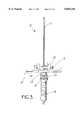
- FIG. 3is front plan view of an IM Alignment Guide.
- FIG. 4is a front plan view of a Distal Placement Guide assembled with a Distal Femoral Cutting Guide according to the present invention.
- FIG. 5is a side plan view of the Distal Placement Guide assembled with the Distal Femoral Cutting Guide of FIG. 4.
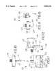
- FIG. 6is a front plan view of an Epicondylar Guide according to the present invention.
- FIG. 7is a side plan view of the Epicondylar Guide of FIG. 6.
- FIG. 8is a front plan view of a Posterior Reference/Rotation Guide according to the present invention.
- FIG. 9is a side plan view of the Posterior Reference/Rotation Guide of FIG. 8.
- FIG. 10is a top plan view of the Posterior Reference/Rotation Guide of FIG. 8.
- FIG. 11is a front plan view of an A/P Cutting Guide according to the present invention.
- FIG. 12is a side plan view of the A/P Cutting Guide of FIG. 11.
- FIG. 13is a bottom plan view of the A/P Cutting Guide of FIG. 11.
- FIG. 14is a front plan view of a Posterior Resection Gauge according to the present invention.
- FIG. 15is a side plan view of the Posterior Resection Gauge of FIG. 14.
- FIG. 16is a front plan view of the IM Alignment Guide of FIG. 3 showing how it is adjusted for valgus angle.
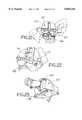
- FIG. 17is a perspective view of the IM Alignment Guide of FIG. 3 inserted into the femur and carrying the Distal Placement Guide and Distal Femoral Cutting Guide of FIG. 4.
- FIG. 18is a perspective view of the distal femur showing how the epicondyles are palpated and marked.
- FIG. 19is a perspective view of the distal femur showing how the epicondylar axis is marked.
- FIG. 20is a perspective view of the Epicondylar Guide of FIG. 6 showing how it is placed on the distal femur in alignment with the epicondylar axis.
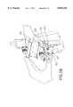
- FIG. 21is a perspective view of the Epicondylar Guide of FIG. 6 being used in conjunction with the Posterior Reference/Rotation Guide of FIG. 8.
- FIG. 22is a perspective view of the Epicondylar Guide of FIG. 6 showing the use of the saw blade scale.
- FIG. 23is a perspective view of the Epicondylar Guide of FIG. 6 showing a slot being cut in the distal femur.
- FIG. 24is plan view showing the distal femur with the slot which was shown being cut in FIG. 23.
- FIG. 25is a perspective view of the A/P Cutting Guide of FIG. 11 being positioned on the distal femur.
- FIG. 26is a perspective view of the A/P Cutting Guide of FIG. 11 being positioned on the distal femur.
- FIG. 27is a perspective view of the Posterior Resection Gauge of FIG. 14 being used in conjunction with the A/P Cutting Guide of FIG. 11.
- FIG. 28is a perspective view of the Posterior Reference/Rotation Guide of FIG. 8 being used in conjunction with the A/P Cutting Guide of FIG. 11.
- FIG. 29is a perspective view of the A/P Cutting Guide of FIG. 11 being used to resect the anterior and posterior femoral condyles.
- FIG. 30is a perspective view of an alternative embodiment of an Epicondylar Guide.
- FIG. 31is a bottom plan view of an alternative embodiment of an A/P Cutting Guide.
- FIG. 32is a perspective view of the A/P Cutting Guide of FIG. 31 in engagement with the Epicondylar Guide of FIG. 30.
- an IM Alignment Guide 6has an IM rod 7 and a handle 8 oriented along a longitudinal axis.
- a base 9is mounted on the handle 8 and IM rod 7 so that it can pivot about an axis normal to the longitudinal axis.
- a valgus angle adjustment knob 10is mounted on the handle 8 for rotation about the longitudinal axis.
- the valgus angle adjustment knob 10has a cam surface 12 that engages the base 9. When the valgus angle adjustment knob 10 is rotated, the cam surface 12 causes the base 9 to pivot about the axis normal to the longitudinal axis.
- the base 9forms an angle with the longitudinal axis that varies with the rotational position of the valgus angle adjustment knob 10.
- the valgus angle adjustment knob 10includes indicia 14 for indicating the angle of the base 9 relative to the IM rod 7. Pins 16 for engaging bone protrude distally from the base 9. A slot 18 is formed in the base 9 for engaging other instruments. The slot 18 provides an opening in the base 9 extending into the base 9 perpendicular to the longitudinal axis. A pair of arms 19 extend laterally from the base 9 perpendicular to the slot 18.
- FIGS. 4 and 5depict a Distal Placement Guide 20 coupled with a Distal Femoral Cutting Guide 30.
- the Distal Placement Guide 20includes an arm 22 and an attachment screw 24.
- the arm 22is shaped to engage the slot 18 in the IM Alignment Guide base 9 in a close sliding fit.
- the Distal Femoral Cutting Guide 30includes a body 32.
- the body 32has a threaded attachment hole for receiving the attachment screw 24.
- a distal cutting slot 34extends through the body 32.
- Fixation holes 36also extend through the body 32.
- An anterior thumb screw 38extends through the body 32 in threaded engagement with the body 32 so that rotation of the thumb screw 38 changes the spacing of the ends of the thumb screw 38 from the body 32.
- the Distal Placement Guide 20is attached to the Distal Femoral Cutting Guide 30 threading the attachment screw 24 into the threaded attachment hole and tightening the attachment screw 24.
- the Distal Placement Guide/Distal Femoral Cutting Guide assemblyis positioned on the IM Alignment Guide by sliding the arm 22 into the slot 18. With these three parts assembled, the distal cutting slot 34 defines a cutting plane that is angled relative to the IM rod 4.
- Two Distal Placement Guides 20are provided. One positions the distal cutting slot 34 at an angle of 0° relative to the IM rod 4 and the other positions the distal cutting slot 34 at an angle of 3° relative to the IM rod 4.
- FIGS. 6 and 7depict an Epicondylar Guide 40.
- the Epicondylar Guide 40includes a central block 42 having a front side 43, a back side 45 and edges 47.
- An elongated A/P slot 44extends through the central block 42 from front 43 to back 45.
- Slender, elongated, epicondylar reference arms 46extend from the central block 42 perpendicular to the A/P slot 44.
- a threaded attachment hole 48is formed in the central block 42.
- Alignment holes 50 and fixation holes 52are formed on the Epicondylar Guide 40 with the fixation holes 52 extending through the Epicondylar Guide 40.
- the central block 42is 22 mm from front 43 to back 45.
- a measurement scale 54is inscribed on a surface of the Epicondylar Guide 40.
- the scale 54is used as a reference to place a mark, such as with a piece of tape, on a saw blade 30 mm from the blade tip. Thus when the blade is inserted into the A/P slot 44 to the mark, it extends 8 mm from the guide to produce an 8 mm slot in the underlying bone.
- FIGS. 8-10depict a Posterior Reference/Rotation Guide 60.
- the Posterior Reference/Rotation Guide 60includes a body 62 having a back surface 67 and a bottom surface 63.
- the back surface 67includes a chamfered notch 69.
- the body 62carries an attachment screw 64 and alignment pins 66.
- a neck 68extends from the bottom surface 63.
- the neck 68includes a femoral A/P position scale 70 preferably comprising multiple marks spaced 2 mm apart. A first mark is labeled "0".
- a second mark, 2 mm from the first mark and closer to the bottom surface 63,is labeled "2".
- a sliding member 72slidingly engages the neck 68.
- the sliding member 72has a top surface 74, a front surface 61 and sides 65.
- the top surface 74opposes the bottom surface 63.
- the sliding member 72is slidable from a first position in which the bottom surface 63 and top surface 74 are near one another and a second position in which the bottom surface 63 and top surface 74 are spaced from one another.
- the sliding member 72obscures portions of the femoral position scale 70 as it slides along the neck 68. By sighting along the top surface 74 of the sliding member 72, the position of the sliding member 72 relative to the femoral position scale 70 can be determined.
- a locking lever 76threadingly engages the sliding member 72 and bears against the neck 68 so that when the locking lever 76 is tightened the sliding member 72 is prevented from sliding along the neck 68.
- a pair of posterior paddle feet 78are rotatably mounted by a pivot 80 on the sliding member 72.
- the pivot 80 axisis parallel to the top surface 74 and is located midway between the feet 78 which rotate as a pair about the pivot 80.
- the feet 78are flat plates with their top surfaces lying in a common plane parallel to the pivot 80 axis.
- Lateral extensions 82extend from the feet 78 and project adjacent the sides 65 of the sliding member.
- An external rotation scale 84is marked on the front surface 61 of the sliding member 72.
- the external rotation scale 84comprises multiple marks angled relative to one another adjacent each side 65 of the sliding member 72.
- a first mark on each sideis labeled "0°” and corresponds to the horizontal position of the feet 78. Subsequent marks are positioned on each side at 3 and 5 degrees above and below the "0°” mark and are labeled "3°” and “5°” accordingly.
- the sets of marksare further labeled to indicate left and right knees.
- the marks on the lefthave the word “LEFT” inscribed below the angle marks and the word “RIGHT” inscribed above the angle marks.
- the marks on the righthave the word “RIGHT” inscribed below the angle marks and the word “LEFT” inscribed above the angle marks.
- a rotation lock 86locks the pivot 80. When the rotation lock 86 is activated by rotating it clockwise, the feet 78 are prevented from rotating relative to the sliding member 72.
- the Posterior Reference/Rotation Guide 60can be mounted on the Epicondylar Guide 40.
- the attachment screw 64threads into the threaded attachment hole 48. With the attachment screw 64 tightened, the Posterior Reference/Rotation Guide 60 is rigidly fixed to the Epicondylar Guide 40.
- the chamfered notch 69seats against the edges 47 so that the Posterior Reference/Rotation Guide 60 is consistently mounted without rotation relative to the Epicondylar Guide 40.
- the feet 78are in the horizontal position, the tops of the feet are in a plane perpendicular to the A/P slot 44 of the Epicondylar Guide 40 and the lateral extensions are aligned with the "0°" marks on the external rotation scale 84.
- the lateral extensionsalign with the left “3°” mark below the "0°” mark corresponding to the quadrant labeled "LEFT” and the right “3°” mark above the "0°” mark corresponding to the quadrant labeled "LEFT”.
- This position of the lateral extensionsthus indicates a left knee in 3° of external rotation.
- the lateral extensions 82 and the external rotation scale 84similarly align to indicate the position of the feet 78 relative to the A/P slot at 3 and 5 degrees above and below the horizontal.
- FIGS. 11-13depict an A/P Cutting Guide 90.
- the A/P Cutting Guide 90includes a cutting block 91 having front 92, back 94, top 96, bottom 98, left 91 and right 93 sides.
- Anterior 100 and posterior 102 cutting slotsextend through the cutting block from front 92 to back 94 perpendicular to the back 94.
- the cutting slots 100 and 102are elongated in the front 92 and back 94 sides and extend from near the left side 91 to near the right side 93.
- a threaded attachment hole 104is formed in the cutting block 91. The threaded attachment hole 104 interrupts the posterior cutting slot 102.
- Alignment holes 106 and fixation holes 108are formed on the cutting block 91 with the fixation holes 108 extending through the cutting block 91.
- a fin 110projects from the back side 94 of the cutting block 91 normal to the back side 94 and perpendicular to the elongated cutting slots 100 and 102.
- An anterior boom 112is pivotally mounted on the top side 96 in a bearing 114.
- the boomis "U" shaped with one end of the "U” being mounted in the bearing 114 and the other end, or probe end 116 lying in a plane parallel to the cutting slots 100 and 102. As the boom 112 is rotated about the bearing 114, the probe end 116 remains in a plane parallel to the cutting slots 100 and 102.
- a locking screw 118threads into the wall of the bearing 114 and prevents the boom 112 from rotating in the bearing 114 when it is tightened.
- the Posterior Reference/Rotation Guide 60(FIGS. 8-10) can be mounted on the A/P Cutting Guide 90 (FIGS. 11-13). Alignment pins 66 engage the alignment holes 106 and the attachment screw 64 threads into the threaded attachment hole 104. With the attachment screw 64 tightened, the Posterior Reference/Rotation Guide 60 is rigidly fixed to the A/P Cutting Guide 90.
- the external rotation scale 84 and lateral extensions 82indicate the angle of the feet 78 relative to the cutting slots 100 and 102 and the fin 110.
- the femoral position scale 70indicates the A/P position of the feet 78 relative to the probe end 116.
- FIGS. 14 and 15depict a Posterior Resection Gauge 120.
- the Posterior Resection Gauge 120includes a gauge body 122 and a wing 124 rotatably mounted to the gauge body 122 at a pivot 126.
- the gauge body 122carries an attachment screw 128 and alignment pins 130.
- the Posterior Resection Gauge 120can be mounted on the A/P Cutting Guide 90. Alignment pins 130 engage the alignment holes 106 and the attachment screw 128 threads into the threaded attachment hole 104. With the attachment screw tightened, the Posterior Resection Guide 120 is rigidly fixed to the A/P Cutting Guide 90.
- the wing 124rotates in a plane that is a predetermined distance from the probe end 116.
- FIGS. 16-29depict the use of the above instruments.
- a holeis drilled in the distal femur collinear with the intramedullary canal.
- the IM Alignment Guide 6is set to the desired valgus angle (FIG. 16) and it is inserted into the hole. If a distal placement guide establishing 3° of flexion will be used, the rotation of the IM Alignment Guide should be set using the epicondylar axis by positioning the arms 19 of the guide relative to the epicondyles. This does not set external rotation, but keeps the distal cut properly oriented to the final component rotation. If a distal placement guide establishing 0° of flexion will be use, then rotation of the IM Guide need not be considered. The IM Alignment Guide 6 is then seated on the most prominent condyle.
- the Distal Femoral Cutting Guide 30is attached to the Distal Placement Guide 20.
- the 3° Distal Placement Guide 20will be used since 3° of flexion affords protection against notching of the anterior femoral cortex. This is especially important when the A/P position, which is set in a subsequent step, is adjusted posteriorly.
- the Distal Placement Guide 20is inserted with the Distal Femoral Cutting Guide 30 into the IM Alignment Guide 6 until the Distal Femoral Cutting Guide 30 comes to rest on the anterior femoral cortex 140 (FIG. 17). With the IM Alignment Guide 6 base 9 flush against the distal condyles, the distal cutting slot 34 is positioned to remove the same amount of bone that will be replaced by the prosthetic femoral component.
- the IM Alignment Guide 6can be removed to ease cutting or it can be left in place if additional support is needed for the Distal Femoral Cutting Guide 30. If it is left in place, care should be taken to cut the bone all around the IM rod 4.
- the distal femur 142is cut through the distal cutting slot 34. The valgus angle is now established.
- femoral rotationis established as shown in FIGS. 18-24.
- the epicondylesare identified in order to determine the epicondylar axis which is the preferred indicator of proper external femoral rotation.
- the lateral epicondyleis identified by dissecting away the patellar femoral ligament.
- the medial epicondylecan be found by removing the synovium from the medial collateral ligament attachment on the femur.
- the location of the epicondylescan be marked on the distal femur 142 with methylene blue 144 (FIG. 18). A line drawn between these two marks represents the epicondylar axis 146 (FIG. 19).
- the Epicondylar Guide 40is placed on the flat surface of the cut distal femur and the epicondyle reference arms 46 are aligned with the epicondylar axis (FIG. 20).
- the back 45 of the Epicondylar Guide 40is flat so that it is stable as it rests on the flat cut distal femur 142. This also allows it to be slid and rotated about on the femur to achieve proper alignment.
- the central block 42is small relative to the cut distal femur 142 so that the epicondylar axis 146 can be easily visualized.
- the epicondylar reference arms 46are long and slender to enhance visualization and clearly indicate alignment of the Epicondylar Guide 40 With the epicondylar axis 146.
- the Epicondylar Guide 40is then pinned in place.
- the amount of external rotation relative to the posterior condylescan be checked at this point as an additional verification of proper external rotation (FIG. 21).
- the Posterior Reference/Rotation Guide 60is attached to the Epicondylar Guide 40 and the feet are brought into contact with the posterior condyles 148.
- the amount of rotation relative to the posterior condylesis then read from the external rotation scale 84.
- a saw bladeis marked at 30 mm to provide a 8 mm depth of cut by comparing the blade to the saw blade scale 54 provided on the Epicondylar Guide 40 (FIG. 22). Using the scale and marking the blade ensures a depth of cut that is not unnecessarily deep but that is deep enough to receive the fin 110 of the A/P Cutting Guide 90.
- a slot 150is then cut in the distal femur through the A/P slot 44 in the Epicondylar Guide 40 to the depth marked on the blade (FIG. 23). The Epicondylar Guide 40 is then removed from the femur. The slot 150 cut into the distal femur establishes the external rotation for subsequent steps and allows A/P position to be set and fine tuned without the distraction of having to simultaneously set external rotation.
- the A/P Cutting Guide 90is placed on the distal femur 142 with its fin 110 engaging the slot 150 cut into the femur (FIG. 25).
- the fin 110is sized to form a press fit in the slot 150 so that the surgeon can temporarily let go of the A/P Cutting Guide 90 without it falling off of the bone.
- the fin 110 and slot 150 engagementallows the A/P Cutting Guide 90 to be moved in the anterior and posterior directions without the A/P Cutting Guide 90 rotating.
- the A/P location of the A/P Cutting Guide 90can be set by tapping the guide posteriorly until the probe end 116 of the anterior boom 112 contacts the anterior femoral cortex 140 (FIG. 27).
- the probe end 116indicates the level of the anterior resection.
- the Posterior Resection Gauge 120is attached to the A/P Cutting Guide 90 to indicate the posterior resection amount (FIG. 27).
- the position of the wing 124indicates the position of the posterior condyles of the femoral component. Note that external rotation results in removal of more bone on the medial posterior condyle.
- the Posterior Reference/Rotation Guide 60may be used in place of the Posterior Resection Gauge 120 to verify femoral sizing and to check rotation (FIG. 28).
- the femoral position scale 70 on the Posterior Reference/Rotation Guide 60is locked to the zero position. This zero setting ensures that when the feet 78 are flush with the posterior condyles, the amount of bone resected posteriorly will equal the posterior thickness of the implant.
- the posterior condyles of the implantwill be positioned where the natural posterior condyles were. This will produce the same flexion gap as the bone did. Note that external rotation results in removal of more bone on the medial posterior condyle.
- the Posterior Reference/Rotation Guide 60is attached to the A/P Cutting Guide 90. If the posterior condyles 148 prevent the guide from seating, because the anterior boom 112 is resting on the anterior femur and prevents the A/P Cutting Guide 90 from moving any further posteriorly, it will be necessary to unlock the femoral position scale 70.
- the resulting femoral position scale 70 readingrepresents the A/P position variance or the increase in flexion gap that will occur if the A/P Cutting Guide is positioned with the anterior boom. Another way of considering the information is that the femoral position scale 70 reading represents the variation from the standard posterior resection that will occur.
- the A/P Cutting Guide 90may be adjusted in order to minimize any potential imbalance in the flexion and extension gaps. For example, after swinging the anterior boom 112 out of contact with the anterior femur, the A/P Cutting Guide can be repositioned posteriorly to reduce the flexion gap. The preferable 3° distal flexion of the femur cut set with the Distal Femoral Cutting Guide 30 facilitates this adjustment and protects against notching of the femoral cortex.
- posterior referencingcan be done first and the anterior boom used as a secondary check.
- the Posterior Reference/Rotation Guide 60is attached to the A/P Cutting Guide 90.
- the femoral position scale 70is locked into the zero position. Both feet 78 of the Posterior Reference/Rotation Guide 60 are positioned in contact with the posterior condyles 148.
- the anterior placement of the guideis checked with the anterior boom 112 to ensure that femoral notching will not occur.
- the probe tip 116 of the anterior boom 112indicates the level of the anterior resection. If the probe tip 116 indicates that notching of the femoral cortex may result, the femoral position scale 70 is unlocked and the A/P Cutting Guide 90 is adjusted anteriorly.
- the subsequent reading on the femoral position scale 70represents the additional resection that will occur posteriorly to fit the femoral component.
- the A/P Cutting Guide 90is pinned in place and the anterior and posterior femoral condyles are cut through the cutting slots 100 and 102 (FIG. 29).
- the valgus angle, external rotation and A/P placement of the femurhave now each been independently and precisely determined.
- the final preparation of the femur and implantation of the femoral componentcan proceed according to standard techniques.
- FIGS. 30-32depict alternative embodiments of the Epicondylar Guide and A/P cutting guide.
- the Epicondylar Guide 160comprises a central block 162.
- a pair of arms 164extends from the central block 162 to provide an axis for aligning the Epicondylar Guide 160 with the epicondylar axis 161.
- the arms 164are preferably removably attached to the central block 162 such as by a threaded engagement.
- the central block 162defines a linear track 166.
- the exemplary embodiment of FIG. 30has a dove tail or T-shaped cross-section.
- the linear track 166is perpendicular to the axis provided by the arms 164.
- the A/P Cutting Guide 168is configured generally like the A/P cutting Guide of FIGS.11-13. However, rather than having a fin like the embodiment of FIGS. 11-13, this alternative A/P Cutting Guide has a slot 170 formed in its back side 172. The slot 172 is perpendicular to the cutting slots 174 and 176. The slot 172 also is configured to engage the linear track 166.
- the Epicondylar Guide 160is positioned on the distal femur 178 and aligned with the epicondylar axis 161. The Epicondylar Guide 160 is then pinned in place and the arms 164 are removed.
- the A/P Cutting Guide 168is placed with the slot 172 engaging the linear track 166.
- the A/P cutting Guide 168is moved anteriorly and posteriorly along the linear track 166 until it is in the desired A/P position.
- the A/P Cutting Guide 168is then pinned in place and the anterior and posterior femoral cuts are made.
- the exemplary embodimentsdepict a saw blade being used to make the anterior and posterior femoral cuts.
- the claimed methods and alignment guidescould just as well be used with a milling system to resect the femoral bone.
- a milling systemis taught in U.S. Pat. No. 5,474,559 issued to Bertin et al. and assigned to Zimmer, Inc.
- the present inventionwould be used for example to set the femoral bases of the femoral milling guide in the desired amount of rotation and in the desired A/P position.
Landscapes
- Health & Medical Sciences (AREA)
- Surgery (AREA)
- Life Sciences & Earth Sciences (AREA)
- Biomedical Technology (AREA)
- Medical Informatics (AREA)
- Oral & Maxillofacial Surgery (AREA)
- Nuclear Medicine, Radiotherapy & Molecular Imaging (AREA)
- Transplantation (AREA)
- Physical Education & Sports Medicine (AREA)
- Engineering & Computer Science (AREA)
- Orthopedic Medicine & Surgery (AREA)
- Heart & Thoracic Surgery (AREA)
- Dentistry (AREA)
- Molecular Biology (AREA)
- Animal Behavior & Ethology (AREA)
- General Health & Medical Sciences (AREA)
- Public Health (AREA)
- Veterinary Medicine (AREA)
- Surgical Instruments (AREA)
- Prostheses (AREA)
Abstract
Description
The present invention relates to instruments for preparing the human femur for receiving a femoral knee implant. More specifically, the present invention relates to a set of instruments for making highly precise anterior and posterior femoral bone cuts.
The implantation of a femoral knee implant involves establishing three critical aspects of the implant's orientation as shown in FIGS. 1-2. First, the valgus angle is determined by the angle of thedistal cut 1 from side to side relative to the transverse axis 2. The valgus angle is important in establishing proper load transfer to the medial and lateral compartments of the knee joint. Second, the external rotation, which is the rotation of the implant about thelongitudinal axis 3, is fixed by the rotation of the anterior 4 and posterior 5 cuts about thelongitudinal axis 3. External rotation affects the patellar tracking of the joint. Third, anterior-to-posterior (A/P) placement, which is the positioning of the implant in the A/P direction, is determined by the A/P position of the anterior 4 and posterior 5 cuts. The A/P placement of the implant affects the tension of the knee joint in flexion. This aspect of implant placement is sometimes referred to as the flexion gap.
Different means for establishing these three critical aspects of orientation have been proposed. An exemplary system is the Insall/Burstein® II Modular Knee System sold by Zimmer, Inc. As detailed in the surgical technique published for the posterior stabilized implants in this system, a rod extending from an intramedullary alignment guide is inserted into the distal end of the uncut femur. The alignment guide is rotated until it is parallel to the cut surface of the tibia or alternatively until it is parallel to the posterior condyles. An anterior femoral cutting guide is placed on the femoral alignment guide and the anterior femoral rough cut is made. This cut establishes the external rotation for the femoral implant because the subsequent final A/P cuts are made by referencing from this initial cut. The A/P placement of the implant is also determined by this first cut. The A/P position of the cut is determined by an anterior locating boom that extends over and rests its tip on the anterior femur. The A/P position of the final A/P cuts are referenced from this initial cut. The valgus angle is determined by placing the distal femoral cutting guide on the I/M alignment guide and pinning it at the desired valgus angle by referencing a scale on the cutting guide. When the distal femur is resected, the valgus angle is fixed.
Another exemplary knee system is detailed in the surgical technique published by Zimmer, Inc. for the cruciate retaining (CR) implants in the NexGen™ Complete Knee Solution. This technique corresponds to the NexGen CR femoral implants. In this system, the first step is sizing the femur with a femoral sizing guide having an intramedullary rod, a boom for contacting the anterior femoral cortex and feet for contacting the posterior condyles. With the guide in place, external rotation can be marked on the femur by drilling through a set of holes provided in the guide. The indicia adjacent the holes indicate the amount of rotation relative to the feet contacting the posterior condyles. After the femoral sizing guide is removed, an I/M alignment guide having an I/M rod extending from a base and handles extending from the base perpendicular to the I/M rod is inserted into the femur. The base of the I/M alignment guide can be angled to different predetermined valgus angles.
With the desired valgus angle locked into the guide, the guide is rotated to the desired external rotation. The external rotation can be set by aligning the guide with the holes drilled during the sizing step. Alternatively, the external rotation can be set by aligning the handles to be parallel with the cut tibia or to be parallel to an imaginary line through the epicondyles of the femur. A/P placement is established with an A/P positioning guide which is attached to the alignment guide and which gauges the position with an anterior boom that contacts the anterior femoral cortex. With the external rotation, valgus angle, and A/P placement established, mounting bases are attached to the femur and the guides are removed. Milling or cutting guides are attached to the mounting bases and milling or cutting of the femoral cuts is carried out.
These examples have described three landmarks which can be used in establishing external rotation. The first is available when the proximal tibial surface has been resected prior to preparation of the femur. In this case an intramedullary guide inserted into the femur can be rotated until it is parallel to the proximal tibial surface. This landmark sets the femoral external rotation to match the angle cut into the tibia. The second landmark is the posterior femoral condyles. When the posterior condyles are not deformed, the guide can be rotated so that it is parallel to the condyles, or in other words so that equal amounts of the posterior condyles are visible. This landmark sets the external rotation to match the anatomic external rotation of the posterior condyles. The third landmark is the epicondyles of the femur. The epicondyles are projections from the femur located proximal to the medial and lateral condyles. The epicondyles can be palpated and it has been found that a line through the epicondyles, or epicondylar axis, corresponds well to the rotational axis of the knee. To use this landmark, the I/M guide is rotated to be parallel to the epicondylar axis.
The present invention provides a set of instruments and a surgical technique that facilitate precise orientation of the femoral implant. Precision is aided by decoupling the determination of A/P placement, valgus angle, and external rotation into three discrete steps. In this way, a surgeon's full concentration can be directed to each element of placement and fine adjustments can readily be made to each. The valgus angle is set first and the distal femoral cut is made using a Distal Femoral Cutting Guide. A preferred Distal Femoral Cutting Guide makes the distal femoral cut correspond to 3° of flexion of the femur. An Epicondylar Guide is configured to ease referencing external rotation from the epicondyles. The narrow elongated guide is easily alignable with the epicondyles when it is placed on the flat distal cut. Its trim shape permits good visualization. The guide is aligned with the epicondylar axis. A Posterior Reference/Rotation Guide can be attached to the Epicondylar Guide to check the rotation relative to the intact posterior condyles to confirm the epicondylar setting. A slot in the guide guides a saw blade to cut a corresponding slot in the distal femur. The Epicondylar Guide is removed. An A/P Cutting Guide has a fin that fits in the slot cut in the distal femur. With the A/P Cutting Guide engaging the slot and resting on the flat distal cut, external rotation is fixed and the A/P Cutting Guide can only move in the A/P direction. The A/P Cutting Guide has an anterior boom that indicates the resection level for the anterior flange and that can be used for setting A/P placement. By moving the guide in the A/P direction, fine adjustments in the flexion gap can be made. Once A/P placement is set, the anterior and posterior cuts are made through slots in the guide. The 3° of flexion of the distal femoral cut helps to prevent notching of the anterior femur when the A/P placement is adjusted posteriorly.
In an alternative embodiment, the Epicondylar Guide comprises a central block defining a linear track and the A/P Cutting Guide comprises a body that engages the linear track. In this embodiment, the Epicondylar Guide is positioned on the distal femur and pinned in place. The A/P Cutting Guide is engaged with the linear track and moved in the A/P direction to the desired position before the anterior and posterior femoral cuts are made.
FIG. 1 is a front plan view of a femur and a tibia showing various axes of the knee joint.
FIG. 2 is a side section view of the distal femur showing the bone cuts which are necessary to prepare the femur to receive a prosthetic implant.
FIG. 3 is front plan view of an IM Alignment Guide.
FIG. 4 is a front plan view of a Distal Placement Guide assembled with a Distal Femoral Cutting Guide according to the present invention.
FIG. 5 is a side plan view of the Distal Placement Guide assembled with the Distal Femoral Cutting Guide of FIG. 4.
FIG. 6 is a front plan view of an Epicondylar Guide according to the present invention.
FIG. 7 is a side plan view of the Epicondylar Guide of FIG. 6.
FIG. 8 is a front plan view of a Posterior Reference/Rotation Guide according to the present invention.
FIG. 9 is a side plan view of the Posterior Reference/Rotation Guide of FIG. 8.
FIG. 10 is a top plan view of the Posterior Reference/Rotation Guide of FIG. 8.
FIG. 11 is a front plan view of an A/P Cutting Guide according to the present invention.
FIG. 12 is a side plan view of the A/P Cutting Guide of FIG. 11.
FIG. 13 is a bottom plan view of the A/P Cutting Guide of FIG. 11.
FIG. 14 is a front plan view of a Posterior Resection Gauge according to the present invention.
FIG. 15 is a side plan view of the Posterior Resection Gauge of FIG. 14.
FIG. 16 is a front plan view of the IM Alignment Guide of FIG. 3 showing how it is adjusted for valgus angle.
FIG. 17 is a perspective view of the IM Alignment Guide of FIG. 3 inserted into the femur and carrying the Distal Placement Guide and Distal Femoral Cutting Guide of FIG. 4.
FIG. 18 is a perspective view of the distal femur showing how the epicondyles are palpated and marked.
FIG. 19 is a perspective view of the distal femur showing how the epicondylar axis is marked.
FIG. 20 is a perspective view of the Epicondylar Guide of FIG. 6 showing how it is placed on the distal femur in alignment with the epicondylar axis.
FIG. 21 is a perspective view of the Epicondylar Guide of FIG. 6 being used in conjunction with the Posterior Reference/Rotation Guide of FIG. 8.
FIG. 22 is a perspective view of the Epicondylar Guide of FIG. 6 showing the use of the saw blade scale.
FIG. 23 is a perspective view of the Epicondylar Guide of FIG. 6 showing a slot being cut in the distal femur.
FIG. 24 is plan view showing the distal femur with the slot which was shown being cut in FIG. 23.
FIG. 25 is a perspective view of the A/P Cutting Guide of FIG. 11 being positioned on the distal femur.
FIG. 26 is a perspective view of the A/P Cutting Guide of FIG. 11 being positioned on the distal femur.
FIG. 27 is a perspective view of the Posterior Resection Gauge of FIG. 14 being used in conjunction with the A/P Cutting Guide of FIG. 11.
FIG. 28 is a perspective view of the Posterior Reference/Rotation Guide of FIG. 8 being used in conjunction with the A/P Cutting Guide of FIG. 11.
FIG. 29 is a perspective view of the A/P Cutting Guide of FIG. 11 being used to resect the anterior and posterior femoral condyles.
FIG. 30 is a perspective view of an alternative embodiment of an Epicondylar Guide.
FIG. 31 is a bottom plan view of an alternative embodiment of an A/P Cutting Guide.
FIG. 32 is a perspective view of the A/P Cutting Guide of FIG. 31 in engagement with the Epicondylar Guide of FIG. 30.
Referring to FIG. 3, anIM Alignment Guide 6 has anIM rod 7 and ahandle 8 oriented along a longitudinal axis. A base 9 is mounted on thehandle 8 andIM rod 7 so that it can pivot about an axis normal to the longitudinal axis. A valgusangle adjustment knob 10 is mounted on thehandle 8 for rotation about the longitudinal axis. The valgusangle adjustment knob 10 has acam surface 12 that engages the base 9. When the valgusangle adjustment knob 10 is rotated, thecam surface 12 causes the base 9 to pivot about the axis normal to the longitudinal axis. The base 9 forms an angle with the longitudinal axis that varies with the rotational position of the valgusangle adjustment knob 10. The valgusangle adjustment knob 10 includesindicia 14 for indicating the angle of the base 9 relative to theIM rod 7.Pins 16 for engaging bone protrude distally from the base 9. Aslot 18 is formed in the base 9 for engaging other instruments. Theslot 18 provides an opening in the base 9 extending into the base 9 perpendicular to the longitudinal axis. A pair ofarms 19 extend laterally from the base 9 perpendicular to theslot 18.
FIGS. 4 and 5 depict aDistal Placement Guide 20 coupled with a DistalFemoral Cutting Guide 30. TheDistal Placement Guide 20 includes anarm 22 and anattachment screw 24. Thearm 22 is shaped to engage theslot 18 in the IM Alignment Guide base 9 in a close sliding fit. The DistalFemoral Cutting Guide 30 includes abody 32. Thebody 32 has a threaded attachment hole for receiving theattachment screw 24. Adistal cutting slot 34 extends through thebody 32. Fixation holes 36 also extend through thebody 32. Ananterior thumb screw 38 extends through thebody 32 in threaded engagement with thebody 32 so that rotation of thethumb screw 38 changes the spacing of the ends of thethumb screw 38 from thebody 32. TheDistal Placement Guide 20 is attached to the DistalFemoral Cutting Guide 30 threading theattachment screw 24 into the threaded attachment hole and tightening theattachment screw 24. The Distal Placement Guide/Distal Femoral Cutting Guide assembly is positioned on the IM Alignment Guide by sliding thearm 22 into theslot 18. With these three parts assembled, thedistal cutting slot 34 defines a cutting plane that is angled relative to the IM rod 4. TwoDistal Placement Guides 20 are provided. One positions thedistal cutting slot 34 at an angle of 0° relative to the IM rod 4 and the other positions thedistal cutting slot 34 at an angle of 3° relative to the IM rod 4.
FIGS. 6 and 7 depict anEpicondylar Guide 40. TheEpicondylar Guide 40 includes acentral block 42 having afront side 43, aback side 45 and edges 47. An elongated A/P slot 44 extends through thecentral block 42 fromfront 43 to back 45. Slender, elongated,epicondylar reference arms 46 extend from thecentral block 42 perpendicular to the A/P slot 44. A threadedattachment hole 48 is formed in thecentral block 42. Alignment holes 50 and fixation holes 52 are formed on theEpicondylar Guide 40 with the fixation holes 52 extending through theEpicondylar Guide 40. Thecentral block 42 is 22 mm fromfront 43 to back 45. Ameasurement scale 54 is inscribed on a surface of theEpicondylar Guide 40. Thescale 54 is used as a reference to place a mark, such as with a piece of tape, on asaw blade 30 mm from the blade tip. Thus when the blade is inserted into the A/P slot 44 to the mark, it extends 8 mm from the guide to produce an 8 mm slot in the underlying bone.
FIGS. 8-10 depict a Posterior Reference/Rotation Guide 60. The Posterior Reference/Rotation Guide 60 includes abody 62 having aback surface 67 and abottom surface 63. Theback surface 67 includes a chamferednotch 69. Thebody 62 carries anattachment screw 64 and alignment pins 66. Aneck 68 extends from thebottom surface 63. Theneck 68 includes a femoral A/P position scale 70 preferably comprising multiple marks spaced 2 mm apart. A first mark is labeled "0". A second mark, 2 mm from the first mark and closer to thebottom surface 63, is labeled "2". A third mark, 2 mm from the first mark and further away from thebottom surface 63, is labeled "2". A slidingmember 72 slidingly engages theneck 68. The slidingmember 72 has atop surface 74, afront surface 61 and sides 65. Thetop surface 74 opposes thebottom surface 63. The slidingmember 72 is slidable from a first position in which thebottom surface 63 andtop surface 74 are near one another and a second position in which thebottom surface 63 andtop surface 74 are spaced from one another. The slidingmember 72 obscures portions of thefemoral position scale 70 as it slides along theneck 68. By sighting along thetop surface 74 of the slidingmember 72, the position of the slidingmember 72 relative to thefemoral position scale 70 can be determined. A lockinglever 76 threadingly engages the slidingmember 72 and bears against theneck 68 so that when the lockinglever 76 is tightened the slidingmember 72 is prevented from sliding along theneck 68. A pair ofposterior paddle feet 78 are rotatably mounted by apivot 80 on the slidingmember 72. Thepivot 80 axis is parallel to thetop surface 74 and is located midway between thefeet 78 which rotate as a pair about thepivot 80. Thefeet 78 are flat plates with their top surfaces lying in a common plane parallel to thepivot 80 axis.Lateral extensions 82 extend from thefeet 78 and project adjacent thesides 65 of the sliding member. Anexternal rotation scale 84 is marked on thefront surface 61 of the slidingmember 72. Theexternal rotation scale 84 comprises multiple marks angled relative to one another adjacent eachside 65 of the slidingmember 72. A first mark on each side is labeled "0°" and corresponds to the horizontal position of thefeet 78. Subsequent marks are positioned on each side at 3 and 5 degrees above and below the "0°" mark and are labeled "3°" and "5°" accordingly. The sets of marks are further labeled to indicate left and right knees. The marks on the left have the word "LEFT" inscribed below the angle marks and the word "RIGHT" inscribed above the angle marks. The marks on the right have the word "RIGHT" inscribed below the angle marks and the word "LEFT" inscribed above the angle marks. Arotation lock 86 locks thepivot 80. When therotation lock 86 is activated by rotating it clockwise, thefeet 78 are prevented from rotating relative to the slidingmember 72.
The Posterior Reference/Rotation Guide 60 can be mounted on theEpicondylar Guide 40. The attachment screw 64 threads into the threadedattachment hole 48. With theattachment screw 64 tightened, the Posterior Reference/Rotation Guide 60 is rigidly fixed to theEpicondylar Guide 40. The chamferednotch 69 seats against theedges 47 so that the Posterior Reference/Rotation Guide 60 is consistently mounted without rotation relative to theEpicondylar Guide 40. When thefeet 78 are in the horizontal position, the tops of the feet are in a plane perpendicular to the A/P slot 44 of theEpicondylar Guide 40 and the lateral extensions are aligned with the "0°" marks on theexternal rotation scale 84. When thefeet 78 are rotated 93 degrees down to the left relative to the A/P slot 44, the lateral extensions align with the left "3°" mark below the "0°" mark corresponding to the quadrant labeled "LEFT" and the right "3°" mark above the "0°" mark corresponding to the quadrant labeled "LEFT". This position of the lateral extensions thus indicates a left knee in 3° of external rotation. Thelateral extensions 82 and theexternal rotation scale 84 similarly align to indicate the position of thefeet 78 relative to the A/P slot at 3 and 5 degrees above and below the horizontal.
FIGS. 11-13 depict an A/P Cutting Guide 90. The A/P Cutting Guide 90 includes a cuttingblock 91 havingfront 92, back 94, top 96, bottom 98, left 91 and right 93 sides. Anterior 100 and posterior 102 cutting slots extend through the cutting block fromfront 92 to back 94 perpendicular to the back 94. The cuttingslots left side 91 to near theright side 93. A threadedattachment hole 104 is formed in the cuttingblock 91. The threadedattachment hole 104 interrupts theposterior cutting slot 102. Alignment holes 106 andfixation holes 108 are formed on the cuttingblock 91 with the fixation holes 108 extending through the cuttingblock 91. Afin 110 projects from theback side 94 of the cuttingblock 91 normal to theback side 94 and perpendicular to theelongated cutting slots anterior boom 112 is pivotally mounted on thetop side 96 in abearing 114. The boom is "U" shaped with one end of the "U" being mounted in thebearing 114 and the other end, or probeend 116 lying in a plane parallel to the cuttingslots boom 112 is rotated about thebearing 114, theprobe end 116 remains in a plane parallel to the cuttingslots screw 118 threads into the wall of thebearing 114 and prevents theboom 112 from rotating in thebearing 114 when it is tightened.
The Posterior Reference/Rotation Guide 60 (FIGS. 8-10) can be mounted on the A/P Cutting Guide 90 (FIGS. 11-13). Alignment pins 66 engage the alignment holes 106 and theattachment screw 64 threads into the threadedattachment hole 104. With theattachment screw 64 tightened, the Posterior Reference/Rotation Guide 60 is rigidly fixed to the A/P Cutting Guide 90. When thefeet 78 are in the horizontal position, the tops of the feet are in a plane parallel to the planes of the cuttingslots fin 110. Theexternal rotation scale 84 andlateral extensions 82 indicate the angle of thefeet 78 relative to the cuttingslots fin 110. Thefemoral position scale 70 indicates the A/P position of thefeet 78 relative to theprobe end 116.
FIGS. 14 and 15 depict aPosterior Resection Gauge 120. ThePosterior Resection Gauge 120 includes agauge body 122 and awing 124 rotatably mounted to thegauge body 122 at apivot 126. Thegauge body 122 carries anattachment screw 128 and alignment pins 130. ThePosterior Resection Gauge 120 can be mounted on the A/P Cutting Guide 90. Alignment pins 130 engage the alignment holes 106 and theattachment screw 128 threads into the threadedattachment hole 104. With the attachment screw tightened, thePosterior Resection Guide 120 is rigidly fixed to the A/P Cutting Guide 90. Thewing 124 rotates in a plane that is a predetermined distance from theprobe end 116.
FIGS. 16-29 depict the use of the above instruments. First, a hole is drilled in the distal femur collinear with the intramedullary canal. TheIM Alignment Guide 6 is set to the desired valgus angle (FIG. 16) and it is inserted into the hole. If a distal placement guide establishing 3° of flexion will be used, the rotation of the IM Alignment Guide should be set using the epicondylar axis by positioning thearms 19 of the guide relative to the epicondyles. This does not set external rotation, but keeps the distal cut properly oriented to the final component rotation. If a distal placement guide establishing 0° of flexion will be use, then rotation of the IM Guide need not be considered. TheIM Alignment Guide 6 is then seated on the most prominent condyle.
Next, the DistalFemoral Cutting Guide 30 is attached to theDistal Placement Guide 20. Normally, the 3°Distal Placement Guide 20 will be used since 3° of flexion affords protection against notching of the anterior femoral cortex. This is especially important when the A/P position, which is set in a subsequent step, is adjusted posteriorly. TheDistal Placement Guide 20 is inserted with the DistalFemoral Cutting Guide 30 into theIM Alignment Guide 6 until the DistalFemoral Cutting Guide 30 comes to rest on the anterior femoral cortex 140 (FIG. 17). With theIM Alignment Guide 6 base 9 flush against the distal condyles, thedistal cutting slot 34 is positioned to remove the same amount of bone that will be replaced by the prosthetic femoral component. Pins are placed through thefixation hole 36 holes in anterior surface of the DistalFemoral Cutting Guide 30 to secure it further to the femur. Theanterior thumb screw 38 is turned until it contacts the anteriorfemoral cortex 140 to further stabilize the cutting guide. TheIM Alignment Guide 6 can be removed to ease cutting or it can be left in place if additional support is needed for the DistalFemoral Cutting Guide 30. If it is left in place, care should be taken to cut the bone all around the IM rod 4. Thedistal femur 142 is cut through thedistal cutting slot 34. The valgus angle is now established.
Next, femoral rotation is established as shown in FIGS. 18-24. Preferably the epicondyles are identified in order to determine the epicondylar axis which is the preferred indicator of proper external femoral rotation. The lateral epicondyle is identified by dissecting away the patellar femoral ligament. The medial epicondyle can be found by removing the synovium from the medial collateral ligament attachment on the femur. The location of the epicondyles can be marked on thedistal femur 142 with methylene blue 144 (FIG. 18). A line drawn between these two marks represents the epicondylar axis 146 (FIG. 19). TheEpicondylar Guide 40 is placed on the flat surface of the cut distal femur and theepicondyle reference arms 46 are aligned with the epicondylar axis (FIG. 20). Theback 45 of theEpicondylar Guide 40 is flat so that it is stable as it rests on the flat cutdistal femur 142. This also allows it to be slid and rotated about on the femur to achieve proper alignment. Thecentral block 42 is small relative to the cutdistal femur 142 so that theepicondylar axis 146 can be easily visualized. Theepicondylar reference arms 46 are long and slender to enhance visualization and clearly indicate alignment of theEpicondylar Guide 40 With theepicondylar axis 146. TheEpicondylar Guide 40 is then pinned in place. The amount of external rotation relative to the posterior condyles can be checked at this point as an additional verification of proper external rotation (FIG. 21). To do this the Posterior Reference/Rotation Guide 60 is attached to theEpicondylar Guide 40 and the feet are brought into contact with theposterior condyles 148. The amount of rotation relative to the posterior condyles is then read from theexternal rotation scale 84. If a valgus knee measures greater than 8° of rotation, or a varus knee greater than 5°, theEpicondylar Guide 40 should be reset within that range. A saw blade is marked at 30 mm to provide a 8 mm depth of cut by comparing the blade to thesaw blade scale 54 provided on the Epicondylar Guide 40 (FIG. 22). Using the scale and marking the blade ensures a depth of cut that is not unnecessarily deep but that is deep enough to receive thefin 110 of the A/P Cutting Guide 90. Aslot 150 is then cut in the distal femur through the A/P slot 44 in theEpicondylar Guide 40 to the depth marked on the blade (FIG. 23). TheEpicondylar Guide 40 is then removed from the femur. Theslot 150 cut into the distal femur establishes the external rotation for subsequent steps and allows A/P position to be set and fine tuned without the distraction of having to simultaneously set external rotation.
The A/P Cutting Guide 90 is placed on thedistal femur 142 with itsfin 110 engaging theslot 150 cut into the femur (FIG. 25). Preferably thefin 110 is sized to form a press fit in theslot 150 so that the surgeon can temporarily let go of the A/P Cutting Guide 90 without it falling off of the bone. Thefin 110 and slot 150 engagement allows the A/P Cutting Guide 90 to be moved in the anterior and posterior directions without the A/P Cutting Guide 90 rotating. The A/P location of the A/P Cutting Guide 90 can be set by tapping the guide posteriorly until theprobe end 116 of theanterior boom 112 contacts the anterior femoral cortex 140 (FIG. 27). Theprobe end 116 indicates the level of the anterior resection. ThePosterior Resection Gauge 120 is attached to the A/P Cutting Guide 90 to indicate the posterior resection amount (FIG. 27). The position of thewing 124 indicates the position of the posterior condyles of the femoral component. Note that external rotation results in removal of more bone on the medial posterior condyle.
Alternatively, the Posterior Reference/Rotation Guide 60 may be used in place of thePosterior Resection Gauge 120 to verify femoral sizing and to check rotation (FIG. 28). First, thefemoral position scale 70 on the Posterior Reference/Rotation Guide 60 is locked to the zero position. This zero setting ensures that when thefeet 78 are flush with the posterior condyles, the amount of bone resected posteriorly will equal the posterior thickness of the implant. Thus the posterior condyles of the implant will be positioned where the natural posterior condyles were. This will produce the same flexion gap as the bone did. Note that external rotation results in removal of more bone on the medial posterior condyle. Next, the Posterior Reference/Rotation Guide 60 is attached to the A/P Cutting Guide 90. If theposterior condyles 148 prevent the guide from seating, because theanterior boom 112 is resting on the anterior femur and prevents the A/P Cutting Guide 90 from moving any further posteriorly, it will be necessary to unlock thefemoral position scale 70. The resultingfemoral position scale 70 reading represents the A/P position variance or the increase in flexion gap that will occur if the A/P Cutting Guide is positioned with the anterior boom. Another way of considering the information is that thefemoral position scale 70 reading represents the variation from the standard posterior resection that will occur. For example, the 2 mm line below the zero setting would indicate that 2 mm additional posterior condyle bone would be resected. Stated another way, the flexion gap would be 2 mm larger than the extension gap. With this information, the A/P Cutting Guide 90 may be adjusted in order to minimize any potential imbalance in the flexion and extension gaps. For example, after swinging theanterior boom 112 out of contact with the anterior femur, the A/P Cutting Guide can be repositioned posteriorly to reduce the flexion gap. The preferable 3° distal flexion of the femur cut set with the DistalFemoral Cutting Guide 30 facilitates this adjustment and protects against notching of the femoral cortex.
Optionally, posterior referencing can be done first and the anterior boom used as a secondary check. In this case the Posterior Reference/Rotation Guide 60 is attached to the A/P Cutting Guide 90. Thefemoral position scale 70 is locked into the zero position. Bothfeet 78 of the Posterior Reference/Rotation Guide 60 are positioned in contact with theposterior condyles 148. The anterior placement of the guide is checked with theanterior boom 112 to ensure that femoral notching will not occur. Theprobe tip 116 of theanterior boom 112 indicates the level of the anterior resection. If theprobe tip 116 indicates that notching of the femoral cortex may result, thefemoral position scale 70 is unlocked and the A/P Cutting Guide 90 is adjusted anteriorly. The subsequent reading on thefemoral position scale 70 represents the additional resection that will occur posteriorly to fit the femoral component.
Once A/P placement has been decided, the A/P Cutting Guide 90 is pinned in place and the anterior and posterior femoral condyles are cut through the cuttingslots 100 and 102 (FIG. 29). The valgus angle, external rotation and A/P placement of the femur have now each been independently and precisely determined. The final preparation of the femur and implantation of the femoral component can proceed according to standard techniques.
FIGS. 30-32 depict alternative embodiments of the Epicondylar Guide and A/P cutting guide. TheEpicondylar Guide 160 comprises acentral block 162. A pair ofarms 164 extends from thecentral block 162 to provide an axis for aligning theEpicondylar Guide 160 with the epicondylar axis 161. Thearms 164 are preferably removably attached to thecentral block 162 such as by a threaded engagement. Thecentral block 162 defines alinear track 166. The exemplary embodiment of FIG. 30 has a dove tail or T-shaped cross-section. Thelinear track 166 is perpendicular to the axis provided by thearms 164.
The A/P Cutting Guide 168 is configured generally like the A/P cutting Guide of FIGS.11-13. However, rather than having a fin like the embodiment of FIGS. 11-13, this alternative A/P Cutting Guide has aslot 170 formed in itsback side 172. Theslot 172 is perpendicular to the cuttingslots slot 172 also is configured to engage thelinear track 166. In use, theEpicondylar Guide 160 is positioned on thedistal femur 178 and aligned with the epicondylar axis 161. TheEpicondylar Guide 160 is then pinned in place and thearms 164 are removed. The A/P Cutting Guide 168 is placed with theslot 172 engaging thelinear track 166. The A/P cutting Guide 168 is moved anteriorly and posteriorly along thelinear track 166 until it is in the desired A/P position. The A/P Cutting Guide 168 is then pinned in place and the anterior and posterior femoral cuts are made.
It will be understood by those skilled in the art that the foregoing has described exemplary embodiments of the present invention and that variations may be made to these embodiments without departing from the spirit and scope of the invention defined by the appended claims. For example the exemplary embodiments depict a saw blade being used to make the anterior and posterior femoral cuts. However, the claimed methods and alignment guides could just as well be used with a milling system to resect the femoral bone. Such a milling system is taught in U.S. Pat. No. 5,474,559 issued to Bertin et al. and assigned to Zimmer, Inc. The present invention would be used for example to set the femoral bases of the femoral milling guide in the desired amount of rotation and in the desired A/P position.
Claims (15)
1. A method for cutting a distal portion of a femur having anterior, posterior, medial and lateral aspects in preparation for implanting a prosthetic femoral component, the method comprising the steps of:
establishing a rotational reference on the distal femur, the rotational reference having a longitudinal axis located generally in the A/P direction;
engaging the rotational reference with an A/P cutting guide, the engagement between the A/P cutting guide and the rotational reference preventing rotation of the A/P cutting guide relative to the rotational reference and constraining the A/P cutting guide to motion along the longitudinal axis of the rotational reference;
adjusting the A/P cutting guide along the longitudinal axis until it is in a desired A/P position; and
cutting the anterior and posterior portions of the distal femur by referencing the A/P cutting guide.
2. The method of claim 1 wherein the step of establishing a rotational reference on the distal femur further includes the steps of:
placing a rotation guide on the distal femur;
orienting the rotation guide to a desired rotational position, the rotation guide having a longitudinal axis that extends in a generally A/P direction on the distal femur.
3. The method of claim 2 wherein, in the step of engaging the rotational reference with the A/P cutting guide, the A/P cutting guide engages the rotation guide.
4. The method of claim 1 wherein the step of establishing a rotational reference on the distal femur further includes the steps of:
placing a rotational guide on the distal femur;
orienting the rotational guide to a desired rotational position;
cutting a slot in the distal femur by referencing the rotational guide, the slot extending in a generally A/P direction on the distal femur.
5. The method of claim 4 wherein the A/P cutting guide has a portion that extends into the slot to constrain the A/P cutting guide to motion along the length of the slot, and the step of engaging the rotational reference with an A/P cutting guide includes placing the portion in the slot.
6. The method of claim 1 wherein the step of establishing the rotational reference includes the steps of locating the femoral epicondyles and orienting the rotational reference so that it is perpendicular to a line between the epicondyles.
7. The method of claim 1 further including, before the step of establishing a rotational reference, the step of cutting the distal femur to provide a flat distal surface.
8. The method of claim 7 wherein the distal femur is cut at approximately 3 degrees of flexion.
9. The method of claim 1 further including, after the step of establishing a rotational reference on the distal femur, the steps of providing a posterior reference guide having extending feet, contacting the posterior condyles with the feet, and reading the amount of rotation of the rotation guide relative to the posterior condyles from an external rotation scale on the posterior reference guide.
10. The method of claim 1 further including, after the step of engaging the rotational reference with an A/P cutting guide, the step of checking the posterior resection amount with a posterior resection gauge attached to the A/P cutting guide.
11. The method of claim 1 further including, after the step of engaging the rotational reference with an A/P cutting guide, providing a posterior reference guide having extending feet, contacting the posterior condyles with the feet, reading the amount of A/P position variance from an A/P position variance scale, and adjusting the A/P cutting guide to produce the desired flexion gap.
12. An A/P cutting guide for guiding a cutting instrument to cut a distal portion of a femur having anterior, posterior, medial and lateral aspects, the distal portion of the femur having a slot cut into it to established thereon a rotational reference, the A/P cutting guide comprising:
a body;
guiding means connected to the body for establishing anterior and posterior cutting planes for the cutting instrument;
engagement means connected to the body for engaging the rotational reference, the engagement means cooperating with the rotational reference to prevent rotation of the body relative to the rotational reference and the engagement means cooperating with the rotational reference to permit translation of the body on the distal femur back and forth between the anterior and posterior aspects of the distal femur, the engagement means comprising a fin extending from the body.
13. The combination of a rotation guide for establishing a rotational reference on a distal portion of a femur and an A/P cutting guide for guiding a cutting instrument to cut a distal portion of a femur having anterior, posterior, medial and lateral aspects, the combination comprising:
a rotation guide having a central block having front and back surfaces;
a rotational reference extending from the front surface, the rotational reference defining a linear track;
a slender elongated reference arm extending from the block perpendicular to the linear track;
an A/P cutting guide having a body, the body including a slot in engagement with the linear track; and
guiding means connected to the body for establishing anterior and posterior cutting planes for the cutting instrument;
the slot cooperating with the linear track to prevent rotation of the body relative to the rotational reference and the slot cooperating with the linear track to permit translation of the body on the distal femur back and forth between the anterior and posterior aspects of the distal femur.
14. A rotation guide for establishing a rotational reference on a distal portion of a femur, the rotation guide comprising:
a central block having front and back surfaces and an elongated slot extending through the block from the front surface to the back surface;
a slender elongated reference arm extending from the block perpendicular to the slot;
a neck extending from the block;
a sliding member in sliding engagement with the neck, the sliding member being slidable from a first position on the neck to a second position on the neck, the first position being nearer to the block than the second position;
an A/P position scale on the rotation guide for indicating the position of the sliding member relative to the block;
a foot extending from the sliding member, the foot being mounted for rotation relative to the sliding member;
an external rotation scale on the rotation guide for indicating how much the foot is rotated relative to the sliding member.
15. An A/P cutting guide for guiding a cutting instrument to cut a distal portion of a femur having anterior, posterior, medial and lateral aspects, the distal portion of the femur having established thereon a rotational reference, the A/P cutting guide comprising:
a body;
guiding means connected to the body for establishing anterior and posterior cutting planes for the cutting instrument;
engagement means connected to the body for engaging the rotational reference, the engagement means cooperating with the rotational reference to prevent rotation of the body relative to the rotational reference and the engagement means cooperating with the rotational reference to permit translation of the body on the distal femur back and forth between the anterior and posterior aspects of the distal femur;
a neck extending from the body;
a sliding member in sliding engagement with the neck, the sliding member being slidable from a first position on the neck to a second position on the neck, the first position being nearer to the body than the second position;
an A/P position scale on the A/P cutting guide for indicating the position of the sliding member relative to the body;
a foot extending from the sliding member, the foot being mounted for rotation relative to the sliding member;
an external rotation scale on the A/P cutting guide for indicating how much the foot is rotated relative to the sliding member.
Priority Applications (1)
| Application Number | Priority Date | Filing Date | Title |
|---|---|---|---|
| US08/742,427US5830216A (en) | 1996-10-30 | 1996-10-30 | Apparatus and method for knee implantation |
Applications Claiming Priority (1)
| Application Number | Priority Date | Filing Date | Title |
|---|---|---|---|
| US08/742,427US5830216A (en) | 1996-10-30 | 1996-10-30 | Apparatus and method for knee implantation |
Publications (1)
| Publication Number | Publication Date |
|---|---|
| US5830216Atrue US5830216A (en) | 1998-11-03 |
Family
ID=24984800
Family Applications (1)
| Application Number | Title | Priority Date | Filing Date |
|---|---|---|---|
| US08/742,427Expired - LifetimeUS5830216A (en) | 1996-10-30 | 1996-10-30 | Apparatus and method for knee implantation |
Country Status (1)
| Country | Link |
|---|---|
| US (1) | US5830216A (en) |
Cited By (85)
| Publication number | Priority date | Publication date | Assignee | Title |
|---|---|---|---|---|
| US6106529A (en)* | 1998-12-18 | 2000-08-22 | Johnson & Johnson Professional, Inc. | Epicondylar axis referencing drill guide |
| WO2001066021A1 (en)* | 2000-03-10 | 2001-09-13 | Smith & Nephew, Inc | A method of arthroplasty on a knee joint and apparatus for use in same |
| US6482209B1 (en) | 2001-06-14 | 2002-11-19 | Gerard A. Engh | Apparatus and method for sculpting the surface of a joint |
| US6558391B2 (en)* | 2000-12-23 | 2003-05-06 | Stryker Technologies Corporation | Methods and tools for femoral resection in primary knee surgery |
| US6575980B1 (en)* | 1997-01-28 | 2003-06-10 | New York Society For The Ruptured And Crippled Maintaining The Hospital For Special Surgery | Method and apparatus for femoral resection |
| US6595997B2 (en) | 2001-02-28 | 2003-07-22 | Howmedica Osteonics Corp. | Methods used in performing femoral and tibial resection in knee surgery |
| US20030163137A1 (en)* | 2002-02-26 | 2003-08-28 | Smucker Donald M. | Patella resection guide |
| US20030171757A1 (en)* | 2002-03-05 | 2003-09-11 | Coon Thomas M. | Minimally invasive total knee arthroplasty method and instrumentation |
| US20030236523A1 (en)* | 2001-06-14 | 2003-12-25 | Johnson Wesley D. | Apparatus and method for minimally invasive total joint replacement |
| US6685711B2 (en) | 2001-02-28 | 2004-02-03 | Howmedica Osteonics Corp. | Apparatus used in performing femoral and tibial resection in knee surgery |
| US20040039394A1 (en)* | 2002-08-26 | 2004-02-26 | Conti Stephen F. | Ankle fusion guide and method |
| US20040039395A1 (en)* | 2002-05-24 | 2004-02-26 | Coon Thomas M. | Instruments for knee surgery and method of use |
| EP1260183A3 (en)* | 2001-05-21 | 2004-05-26 | NEMCO Medical Ltd. | Femoral knee saw guide and method |
| US6758850B2 (en) | 2002-03-29 | 2004-07-06 | Depuy Orthopaedics, Inc. | Instruments and methods for flexion gap adjustment |
| US20040153066A1 (en)* | 2003-02-03 | 2004-08-05 | Coon Thomas M. | Apparatus for knee surgery and method of use |
| US20040153081A1 (en)* | 2003-02-04 | 2004-08-05 | Howmedica Osteonics Corp. | Femoral guide and pivoting reamer |
| US20040193175A1 (en)* | 2003-03-31 | 2004-09-30 | Maroney Brian J | Arthroplasty sizing gauge |
| US20050049603A1 (en)* | 2002-07-23 | 2005-03-03 | Ortho Development Corporation | Knee balancing block |
| US20050209597A1 (en)* | 2004-03-05 | 2005-09-22 | Long Jack F | Surface replacement extractor device and associated method |
| US20050267484A1 (en)* | 2005-08-18 | 2005-12-01 | Jeff Menzner | Extended trochanteric osteotomy guide |
| US20060004373A1 (en)* | 2004-06-30 | 2006-01-05 | Ondrla Jeffrey M | Adjustable humeral cutting guide |
| US20060142778A1 (en)* | 2004-12-21 | 2006-06-29 | Dees Roger R Jr | Rotational alignment femoral sizing guide |
| US20060249694A1 (en)* | 2003-01-30 | 2006-11-09 | Godfried Herman P | Marking of diamond |
| US20060293681A1 (en)* | 2005-06-13 | 2006-12-28 | Jody Claypool | Adjustable cut guide |
| US20070233137A1 (en)* | 2006-02-15 | 2007-10-04 | Jai-Gon Seo | Tibia cutter |
| US20080065226A1 (en)* | 2003-03-31 | 2008-03-13 | Depuy Products, Inc. | Prosthetic implant, trial and associated method |
| US20080097450A1 (en)* | 2006-09-14 | 2008-04-24 | Zimmer Technology, Inc. | Patella clamp |
| US20080140212A1 (en)* | 2001-05-15 | 2008-06-12 | Robert Metzger | Elongated femoral component |
| WO2008043021A3 (en)* | 2006-10-04 | 2008-07-24 | Smith & Nephew Inc | Device and method for distal resections of a knee prosthetic |
| US20080228189A1 (en)* | 2007-03-13 | 2008-09-18 | Biomet Manufacturing Corp | Distal femoral cutting guide |
| US20080243127A1 (en)* | 2001-05-25 | 2008-10-02 | Conformis, Inc. | Surgical Tools for Arthroplasty |
| US20080287958A1 (en)* | 2007-05-14 | 2008-11-20 | Howmedica Osteonics Corp. | Flexible intramedullary rod |
| AU2005244501B2 (en)* | 2000-03-10 | 2009-01-22 | Smith & Nephew, Inc. | A method of arthroplastly on a knee joint and apparatus for use in same |
| US7507242B2 (en) | 2004-06-02 | 2009-03-24 | Facet Solutions | Surgical measurement and resection framework |
| US20090192622A1 (en)* | 2003-03-31 | 2009-07-30 | Depuy Products, Inc. | Extended Articulation Orthopaedic Implant |
| US7611540B2 (en)* | 2007-05-01 | 2009-11-03 | Moximed, Inc. | Extra-articular implantable mechanical energy absorbing systems and implantation method |
| US7618421B2 (en) | 2001-10-10 | 2009-11-17 | Howmedica Osteonics Corp. | Tools for femoral resection in knee surgery |
| US20100057088A1 (en)* | 2008-08-26 | 2010-03-04 | Maxx Orthopedics, Inc. | Distal Femoral Cutting Guide |
| US20100160914A1 (en)* | 2006-03-06 | 2010-06-24 | Howmedica Osteonics Corp. | Single use resection guide |
| US20100217338A1 (en)* | 2009-02-24 | 2010-08-26 | Wright Medical Technology, Inc. | Patient Specific Surgical Guide Locator and Mount |
| US7799084B2 (en) | 2002-10-23 | 2010-09-21 | Mako Surgical Corp. | Modular femoral component for a total knee joint replacement for minimally invasive implantation |
| US20100292694A1 (en)* | 2007-09-21 | 2010-11-18 | Depuy International Limited | Intramedullary rod instrument |
| US20100305575A1 (en)* | 2009-05-29 | 2010-12-02 | Zachary Christopher Wilkinson | Methods and Apparatus for Performing Knee Arthroplasty |
| EP2277460A1 (en) | 2009-07-24 | 2011-01-26 | Tornier | Surgical instrumentation for preparing the setting of a knee prosthesis |
| US7909831B2 (en) | 2001-02-28 | 2011-03-22 | Howmedica Osteonics Corp. | Systems used in performing femoral and tibial resection in knee surgery |
| US20110112542A1 (en)* | 2009-11-10 | 2011-05-12 | Wright Medical Technology, Inc. | Adjustable revision guide |
| US20110184413A1 (en)* | 2006-05-17 | 2011-07-28 | Gordon Slater | Ankle Fusion Plate |
| US20110263971A1 (en)* | 2010-04-22 | 2011-10-27 | Constantinos Nikou | Reconfigurable Navigated Surgical Tool Tracker |
| US8066708B2 (en) | 2001-05-25 | 2011-11-29 | Conformis, Inc. | Patient selectable joint arthroplasty devices and surgical tools |
| US8105327B2 (en) | 2003-03-31 | 2012-01-31 | Depuy Products, Inc. | Punch, implant and associated method |
| US8122582B2 (en) | 2001-05-25 | 2012-02-28 | Conformis, Inc. | Surgical tools facilitating increased accuracy, speed and simplicity in performing joint arthroplasty |
| US8343218B2 (en) | 2001-05-25 | 2013-01-01 | Conformis, Inc. | Methods and compositions for articular repair |
| US8366713B2 (en) | 2003-03-31 | 2013-02-05 | Depuy Products, Inc. | Arthroplasty instruments and associated method |
| US8377129B2 (en) | 2001-05-25 | 2013-02-19 | Conformis, Inc. | Joint arthroplasty devices and surgical tools |
| US8439926B2 (en) | 2001-05-25 | 2013-05-14 | Conformis, Inc. | Patient selectable joint arthroplasty devices and surgical tools |
| US20130158556A1 (en)* | 2011-12-19 | 2013-06-20 | Zimmer, Inc. | Surgical cutting guide |
| US8500740B2 (en) | 2006-02-06 | 2013-08-06 | Conformis, Inc. | Patient-specific joint arthroplasty devices for ligament repair |
| US20130226185A1 (en)* | 2000-01-14 | 2013-08-29 | Bonutti Skeletal Innovations Llc | Femoral guide for knee surgery |
| US8545506B2 (en) | 2003-03-31 | 2013-10-01 | DePuy Synthes Products, LLC | Cutting guide for use with an extended articulation orthopaedic implant |
| US20130338671A1 (en)* | 2010-11-18 | 2013-12-19 | Depuy (Ireland) | Angular adjustment mechanism, surgical alignment guide and surgical instrument assembly |
| US8623026B2 (en) | 2006-02-06 | 2014-01-07 | Conformis, Inc. | Patient selectable joint arthroplasty devices and surgical tools incorporating anatomical relief |
| US8747410B2 (en) | 2010-10-26 | 2014-06-10 | Zimmer, Inc. | Patellar resection instrument with variable depth guide |
| US20140194884A1 (en)* | 2006-03-09 | 2014-07-10 | Microport Orthopedics Holdings Inc. | Instruments for total knee arthroplasty |
| US8784495B2 (en) | 2000-01-14 | 2014-07-22 | Bonutti Skeletal Innovations Llc | Segmental knee arthroplasty |
| US8808303B2 (en) | 2009-02-24 | 2014-08-19 | Microport Orthopedics Holdings Inc. | Orthopedic surgical guide |
| US8834490B2 (en) | 2001-08-28 | 2014-09-16 | Bonutti Skeletal Innovations Llc | Method for robotic arthroplasty using navigation |
| US8894714B2 (en) | 2007-05-01 | 2014-11-25 | Moximed, Inc. | Unlinked implantable knee unloading device |
| US8951260B2 (en) | 2001-05-25 | 2015-02-10 | Conformis, Inc. | Surgical cutting guide |
| WO2015035466A1 (en)* | 2013-09-12 | 2015-03-19 | Trochlear Pty Ltd | A surgical jig |
| US9119635B2 (en) | 2010-11-18 | 2015-09-01 | Depuy (Ireland) | Surgical cutting guide, surgical alignment guide and surgical instrument system |
| US9186162B2 (en) | 2011-10-27 | 2015-11-17 | Smith & Nephew, Inc. | Devices and methods for performing knee arthroplasty |
| US9486226B2 (en) | 2012-04-18 | 2016-11-08 | Conformis, Inc. | Tibial guides, tools, and techniques for resecting the tibial plateau |
| US20160374699A1 (en)* | 2011-02-11 | 2016-12-29 | Biomet Manufacturing, Llc | Method and apparatus for performing knee arthroplasty |
| US9649117B2 (en) | 2009-02-24 | 2017-05-16 | Microport Orthopedics Holdings, Inc. | Orthopedic surgical guide |
| US9675471B2 (en) | 2012-06-11 | 2017-06-13 | Conformis, Inc. | Devices, techniques and methods for assessing joint spacing, balancing soft tissues and obtaining desired kinematics for joint implant components |
| US9730712B2 (en) | 2012-10-18 | 2017-08-15 | Smith & Nephew, Inc. | Alignment devices and methods |
| US10299801B2 (en) | 2013-04-12 | 2019-05-28 | Depuy Ireland Unlimited Company | Distal femoral jig assembly |
| US10357255B2 (en) | 2015-10-08 | 2019-07-23 | Howmedica Osteonics Corp. | Globalized total knee instrumentation |
| US10716682B2 (en) | 2017-07-19 | 2020-07-21 | Acumed Llc | Orthopedic alignment guide |
| US11123085B2 (en) | 2018-04-11 | 2021-09-21 | Howmedica Osteonics Corp. | Cutting tool positioned by flexible rod for revision surgery |
| US20230371959A1 (en)* | 2020-10-19 | 2023-11-23 | Aesculap Ag | Distal femur alignment system |
| US12108959B2 (en) | 2019-05-29 | 2024-10-08 | Wright Medical Technology, Inc. | Preparing a tibia for receiving tibial implant component of a replacement ankle |
| US12383287B2 (en) | 2009-02-24 | 2025-08-12 | Microport Orthopedics Holdings, Inc. | Systems and methods for installing an orthopedic implant |
| US12396739B2 (en) | 2020-01-17 | 2025-08-26 | Wright Medical Technology, Inc. | Guidance tools, systems, and methods |
| US12440227B2 (en) | 2022-01-05 | 2025-10-14 | Wright Medical Technology, Inc. | Preparing a tibia for receiving tibial implant component of a replacement ankle |
Citations (54)
| Publication number | Priority date | Publication date | Assignee | Title |
|---|---|---|---|---|
| USD272854S (en) | 1981-12-31 | 1984-02-28 | Witte Paul A | Distal femoral resection guide |
| USD273895S (en) | 1982-02-18 | 1984-05-15 | Howmedica, Inc. | Femoral cutting jig for the implantation of a prosthetic knee |
| USD274091S (en) | 1982-02-18 | 1984-05-29 | Howmedica, Inc. | Femoral chamfer cutting jig for the implantation of a prosthetic knee |
| USD274092S (en) | 1982-02-18 | 1984-05-29 | Howmedica, Inc. | Femoral chamfer cutting jig for the implantation of a prosthetic knee |
| USD274090S (en) | 1982-02-18 | 1984-05-29 | Howmedica, Inc. | Transverse tibial cutting jig for the implantation of a prosthetic knee |
| USD274162S (en) | 1982-02-18 | 1984-06-05 | Howmedica, Inc. | Distal femoral cutting jig for the implantation of a prosthetic knee |
| USD274161S (en) | 1982-02-18 | 1984-06-05 | Howmedica, Inc. | Distal femoral cutting jig for the implantation of a prosthetic knee |
| US4474177A (en)* | 1983-03-09 | 1984-10-02 | Wright Manufacturing Company | Method and apparatus for shaping a distal femoral surface |
| US4487203A (en)* | 1981-11-03 | 1984-12-11 | Androphy Gary W | Triplanar knee resection method |
| US4502483A (en)* | 1983-03-09 | 1985-03-05 | Dow Corning Corporation | Method and apparatus for shaping a distal femoral surface |
| US4524766A (en)* | 1982-01-07 | 1985-06-25 | Petersen Thomas D | Surgical knee alignment method and system |
| US4646729A (en)* | 1982-02-18 | 1987-03-03 | Howmedica, Inc. | Prosthetic knee implantation |
| US4653488A (en)* | 1982-02-18 | 1987-03-31 | Howmedica, Inc. | Prosthetic knee implantation |
| US4703751A (en)* | 1986-03-27 | 1987-11-03 | Pohl Kenneth P | Method and apparatus for resecting a distal femoral surface |
| US4722330A (en)* | 1986-04-22 | 1988-02-02 | Dow Corning Wright Corporation | Femoral surface shaping guide for knee implants |
| US4738253A (en)* | 1981-12-31 | 1988-04-19 | Biomedical Engineering Trust | Guides for inclined surgical cuts or resections |
| US4738254A (en)* | 1981-12-31 | 1988-04-19 | Biomedical Engineering Trust | Positioner for surgical instruments |
| US4759350A (en)* | 1986-10-17 | 1988-07-26 | Dunn Harold K | Instruments for shaping distal femoral and proximal tibial surfaces |
| US4787383A (en)* | 1985-12-19 | 1988-11-29 | Howmedica, Inc. | Prosthetic knee implantation |
| US4791919A (en)* | 1985-01-25 | 1988-12-20 | Chas F Thackray Limited | Surgical instruments |
| US4825857A (en)* | 1982-02-18 | 1989-05-02 | Howmedica, Inc. | Prosthetic knee implantation |
| US4841975A (en)* | 1987-04-15 | 1989-06-27 | Cemax, Inc. | Preoperative planning of bone cuts and joint replacement using radiant energy scan imaging |
| US4892093A (en)* | 1988-10-28 | 1990-01-09 | Osteonics Corp. | Femoral cutting guide |
| US4907578A (en)* | 1986-07-23 | 1990-03-13 | Petersen Thomas D | Method and instruments for resection of the distal femur |
| US4938762A (en)* | 1987-12-16 | 1990-07-03 | Protek Ag | Reference system for implantation of condylar total knee prostheses |
| US4944760A (en)* | 1983-10-26 | 1990-07-31 | Pfizer Hospital Products Group, Inc. | Method and instrumentation for the replacement of a knee prosthesis |
| EP0380451A2 (en)* | 1989-01-11 | 1990-08-01 | G. CREMASCOLI S.p.A. | Apparatus for resecting femurs and applying knee articulation prostheses |
| US5002547A (en)* | 1987-02-07 | 1991-03-26 | Pfizer Hospital Products Group, Inc. | Apparatus for knee prosthesis |
| US5037423A (en)* | 1983-10-26 | 1991-08-06 | Pfizer Hospital Products Group, Inc. | Method and instrumentation for the replacement of a knee prosthesis |
| US5053037A (en)* | 1991-03-07 | 1991-10-01 | Smith & Nephew Richards Inc. | Femoral instrumentation for long stem surgery |
| US5100408A (en)* | 1991-03-07 | 1992-03-31 | Smith & Nephew Richards Inc. | Femoral instrumentation for long stem surgery |
| US5116338A (en)* | 1988-02-03 | 1992-05-26 | Pfizer Hospital Products Group, Inc. | Apparatus for knee prosthesis |
| US5122144A (en)* | 1989-09-26 | 1992-06-16 | Kirschner Medical Corporation | Method and instrumentation for unicompartmental total knee arthroplasty |
| US5129909A (en)* | 1991-03-13 | 1992-07-14 | Sutherland Charles J | Apparatus and method for making precise bone cuts in total knee replacement |
| US5250050A (en)* | 1987-02-07 | 1993-10-05 | Pfizer Hospital Products Group, Inc. | Apparatus for knee prosthesis |
| US5364401A (en)* | 1992-10-08 | 1994-11-15 | Wright Medical Technology, Inc. | External alignment system for preparing a femur for an implant |
| USD355254S (en) | 1993-10-29 | 1995-02-07 | Zimmer, Inc. | Bone cutting guide |
| US5405349A (en)* | 1993-11-24 | 1995-04-11 | Intermedics Orthopedics, Inc. | Cutting jig for posterior stabilized knee prosthesis |
| US5411505A (en)* | 1994-06-02 | 1995-05-02 | Intermedics Orthopedics, Inc. | Sagittal saw jig for femoral knee revision prosthesis |
| US5415633A (en)* | 1993-07-28 | 1995-05-16 | Active Control Experts, Inc. | Remotely steered catheterization device |
| US5417694A (en)* | 1993-11-08 | 1995-05-23 | Smith & Nephew Richards Inc. | Distal femoral cutting guide apparatus with anterior or posterior referencing for use in knee joint replacement surgery |
| US5417693A (en)* | 1992-06-17 | 1995-05-23 | Minnesota Mining And Manufacturing Company | Instrumentation for preparing the femur for an artificial knee implant and for positioning the femoral component of the implant |
| US5423822A (en)* | 1993-01-27 | 1995-06-13 | Biomet, Inc. | Method and apparatus for preparing a bone for receiving a prosthetic device |
| US5423827A (en)* | 1994-06-02 | 1995-06-13 | Intermedics Orthopedics, Inc. | Surgical jig for femoral knee prosthesis |
| US5445642A (en)* | 1992-09-01 | 1995-08-29 | Depuy Inc. | Method for installing a femoral component |
| US5454816A (en)* | 1992-02-07 | 1995-10-03 | Howmedica International Inc. | Femoral cutting guide |
| US5458645A (en)* | 1992-04-03 | 1995-10-17 | Bertin; Kim C. | Method for resecting the knee using a resection guide and provisional prosthetic component |
| US5464406A (en)* | 1992-12-09 | 1995-11-07 | Ritter; Merrill A. | Instrumentation for revision surgery |
| US5474559A (en)* | 1993-07-06 | 1995-12-12 | Zimmer, Inc. | Femoral milling instrumentation for use in total knee arthroplasty with optional cutting guide attachment |
| US5484446A (en)* | 1994-06-27 | 1996-01-16 | Zimmer, Inc. | Alignment guide for use in orthopaedic surgery |
| US5486178A (en)* | 1994-02-16 | 1996-01-23 | Hodge; W. Andrew | Femoral preparation instrumentation system and method |
| US5490854A (en)* | 1992-02-20 | 1996-02-13 | Synvasive Technology, Inc. | Surgical cutting block and method of use |
| US5490855A (en)* | 1992-06-16 | 1996-02-13 | Developpement D'implants Orthopediques Et Medicaux | Device to stabilze a cutting means for the fitting of a prosthesis in bone surgery |
| USD367706S (en) | 1994-05-09 | 1996-03-05 | Zimmer, Inc. | Alignment guide for an orthopaedic bone cutting guide |
- 1996
- 1996-10-30USUS08/742,427patent/US5830216A/ennot_activeExpired - Lifetime
Patent Citations (57)
| Publication number | Priority date | Publication date | Assignee | Title |
|---|---|---|---|---|
| US4487203A (en)* | 1981-11-03 | 1984-12-11 | Androphy Gary W | Triplanar knee resection method |
| USD272854S (en) | 1981-12-31 | 1984-02-28 | Witte Paul A | Distal femoral resection guide |
| US4738254A (en)* | 1981-12-31 | 1988-04-19 | Biomedical Engineering Trust | Positioner for surgical instruments |
| US4738253A (en)* | 1981-12-31 | 1988-04-19 | Biomedical Engineering Trust | Guides for inclined surgical cuts or resections |
| US4524766A (en)* | 1982-01-07 | 1985-06-25 | Petersen Thomas D | Surgical knee alignment method and system |
| US4653488A (en)* | 1982-02-18 | 1987-03-31 | Howmedica, Inc. | Prosthetic knee implantation |
| USD274092S (en) | 1982-02-18 | 1984-05-29 | Howmedica, Inc. | Femoral chamfer cutting jig for the implantation of a prosthetic knee |
| USD274161S (en) | 1982-02-18 | 1984-06-05 | Howmedica, Inc. | Distal femoral cutting jig for the implantation of a prosthetic knee |
| USD274162S (en) | 1982-02-18 | 1984-06-05 | Howmedica, Inc. | Distal femoral cutting jig for the implantation of a prosthetic knee |
| US4825857A (en)* | 1982-02-18 | 1989-05-02 | Howmedica, Inc. | Prosthetic knee implantation |
| USD274090S (en) | 1982-02-18 | 1984-05-29 | Howmedica, Inc. | Transverse tibial cutting jig for the implantation of a prosthetic knee |
| US4646729A (en)* | 1982-02-18 | 1987-03-03 | Howmedica, Inc. | Prosthetic knee implantation |
| USD274091S (en) | 1982-02-18 | 1984-05-29 | Howmedica, Inc. | Femoral chamfer cutting jig for the implantation of a prosthetic knee |
| USD273895S (en) | 1982-02-18 | 1984-05-15 | Howmedica, Inc. | Femoral cutting jig for the implantation of a prosthetic knee |
| US4502483A (en)* | 1983-03-09 | 1985-03-05 | Dow Corning Corporation | Method and apparatus for shaping a distal femoral surface |
| US4474177A (en)* | 1983-03-09 | 1984-10-02 | Wright Manufacturing Company | Method and apparatus for shaping a distal femoral surface |
| US5037423A (en)* | 1983-10-26 | 1991-08-06 | Pfizer Hospital Products Group, Inc. | Method and instrumentation for the replacement of a knee prosthesis |
| US4944760A (en)* | 1983-10-26 | 1990-07-31 | Pfizer Hospital Products Group, Inc. | Method and instrumentation for the replacement of a knee prosthesis |
| US4791919A (en)* | 1985-01-25 | 1988-12-20 | Chas F Thackray Limited | Surgical instruments |
| US4787383A (en)* | 1985-12-19 | 1988-11-29 | Howmedica, Inc. | Prosthetic knee implantation |
| US4703751A (en)* | 1986-03-27 | 1987-11-03 | Pohl Kenneth P | Method and apparatus for resecting a distal femoral surface |
| US4722330A (en)* | 1986-04-22 | 1988-02-02 | Dow Corning Wright Corporation | Femoral surface shaping guide for knee implants |
| US4907578A (en)* | 1986-07-23 | 1990-03-13 | Petersen Thomas D | Method and instruments for resection of the distal femur |
| US4759350A (en)* | 1986-10-17 | 1988-07-26 | Dunn Harold K | Instruments for shaping distal femoral and proximal tibial surfaces |
| US5002547A (en)* | 1987-02-07 | 1991-03-26 | Pfizer Hospital Products Group, Inc. | Apparatus for knee prosthesis |
| US5250050A (en)* | 1987-02-07 | 1993-10-05 | Pfizer Hospital Products Group, Inc. | Apparatus for knee prosthesis |
| US4841975A (en)* | 1987-04-15 | 1989-06-27 | Cemax, Inc. | Preoperative planning of bone cuts and joint replacement using radiant energy scan imaging |
| US4938762A (en)* | 1987-12-16 | 1990-07-03 | Protek Ag | Reference system for implantation of condylar total knee prostheses |
| US5116338A (en)* | 1988-02-03 | 1992-05-26 | Pfizer Hospital Products Group, Inc. | Apparatus for knee prosthesis |
| US4892093A (en)* | 1988-10-28 | 1990-01-09 | Osteonics Corp. | Femoral cutting guide |
| EP0380451A2 (en)* | 1989-01-11 | 1990-08-01 | G. CREMASCOLI S.p.A. | Apparatus for resecting femurs and applying knee articulation prostheses |
| US5122144A (en)* | 1989-09-26 | 1992-06-16 | Kirschner Medical Corporation | Method and instrumentation for unicompartmental total knee arthroplasty |
| US5282803A (en)* | 1991-03-07 | 1994-02-01 | Smith & Nephew Richards Inc. | Instrumentation for long stem surgery |
| US5100408A (en)* | 1991-03-07 | 1992-03-31 | Smith & Nephew Richards Inc. | Femoral instrumentation for long stem surgery |
| US5053037A (en)* | 1991-03-07 | 1991-10-01 | Smith & Nephew Richards Inc. | Femoral instrumentation for long stem surgery |
| US5129909A (en)* | 1991-03-13 | 1992-07-14 | Sutherland Charles J | Apparatus and method for making precise bone cuts in total knee replacement |
| US5454816A (en)* | 1992-02-07 | 1995-10-03 | Howmedica International Inc. | Femoral cutting guide |
| US5490854A (en)* | 1992-02-20 | 1996-02-13 | Synvasive Technology, Inc. | Surgical cutting block and method of use |
| US5458645A (en)* | 1992-04-03 | 1995-10-17 | Bertin; Kim C. | Method for resecting the knee using a resection guide and provisional prosthetic component |
| US5490855A (en)* | 1992-06-16 | 1996-02-13 | Developpement D'implants Orthopediques Et Medicaux | Device to stabilze a cutting means for the fitting of a prosthesis in bone surgery |
| US5417693A (en)* | 1992-06-17 | 1995-05-23 | Minnesota Mining And Manufacturing Company | Instrumentation for preparing the femur for an artificial knee implant and for positioning the femoral component of the implant |
| US5445642A (en)* | 1992-09-01 | 1995-08-29 | Depuy Inc. | Method for installing a femoral component |
| US5364401A (en)* | 1992-10-08 | 1994-11-15 | Wright Medical Technology, Inc. | External alignment system for preparing a femur for an implant |
| US5464406A (en)* | 1992-12-09 | 1995-11-07 | Ritter; Merrill A. | Instrumentation for revision surgery |
| US5423822A (en)* | 1993-01-27 | 1995-06-13 | Biomet, Inc. | Method and apparatus for preparing a bone for receiving a prosthetic device |
| US5474559A (en)* | 1993-07-06 | 1995-12-12 | Zimmer, Inc. | Femoral milling instrumentation for use in total knee arthroplasty with optional cutting guide attachment |
| US5415633A (en)* | 1993-07-28 | 1995-05-16 | Active Control Experts, Inc. | Remotely steered catheterization device |
| USD355254S (en) | 1993-10-29 | 1995-02-07 | Zimmer, Inc. | Bone cutting guide |
| US5417694A (en)* | 1993-11-08 | 1995-05-23 | Smith & Nephew Richards Inc. | Distal femoral cutting guide apparatus with anterior or posterior referencing for use in knee joint replacement surgery |
| US5569261A (en)* | 1993-11-08 | 1996-10-29 | Smith & Nephew Richards Inc. | Distal femoral cutting guide apparatus with anterior or posterior referencing for use in knee joint replacement surgery |
| US5405349A (en)* | 1993-11-24 | 1995-04-11 | Intermedics Orthopedics, Inc. | Cutting jig for posterior stabilized knee prosthesis |
| US5486178A (en)* | 1994-02-16 | 1996-01-23 | Hodge; W. Andrew | Femoral preparation instrumentation system and method |
| USD367706S (en) | 1994-05-09 | 1996-03-05 | Zimmer, Inc. | Alignment guide for an orthopaedic bone cutting guide |
| US5423827A (en)* | 1994-06-02 | 1995-06-13 | Intermedics Orthopedics, Inc. | Surgical jig for femoral knee prosthesis |
| US5411505A (en)* | 1994-06-02 | 1995-05-02 | Intermedics Orthopedics, Inc. | Sagittal saw jig for femoral knee revision prosthesis |
| WO1995033413A1 (en)* | 1994-06-02 | 1995-12-14 | Intermedics Orthopedics, Inc. | Surgical jig for femoral knee prosthesis |
| US5484446A (en)* | 1994-06-27 | 1996-01-16 | Zimmer, Inc. | Alignment guide for use in orthopaedic surgery |
Non-Patent Citations (4)
| Title |
|---|
| Zimmer, Inc. Insall/Burstein Posterior Stabilized II Modular Knee System Brochure c1989 Lit. No. 97 5220 02.* |
| Zimmer, Inc. NexGen Complete Knee Solution Brochure c1995 Lit. No. 97 5970 102 Rev. 1.* |
| Zimmer, Inc.--Insall/Burstein Posterior Stabilized II Modular Knee System Brochure--c1989--Lit. No. 97-5220-02. |
| Zimmer, Inc.--NexGen® Complete Knee Solution Brochure--c1995--Lit. No. 97-5970-102 Rev. 1. |
Cited By (274)
| Publication number | Priority date | Publication date | Assignee | Title |
|---|---|---|---|---|
| US6575980B1 (en)* | 1997-01-28 | 2003-06-10 | New York Society For The Ruptured And Crippled Maintaining The Hospital For Special Surgery | Method and apparatus for femoral resection |
| US6106529A (en)* | 1998-12-18 | 2000-08-22 | Johnson & Johnson Professional, Inc. | Epicondylar axis referencing drill guide |
| US9192459B2 (en) | 2000-01-14 | 2015-11-24 | Bonutti Skeletal Innovations Llc | Method of performing total knee arthroplasty |
| US9795394B2 (en) | 2000-01-14 | 2017-10-24 | Bonutti Skeletal Innovations Llc | Method for placing implant using robotic system |
| US20130226185A1 (en)* | 2000-01-14 | 2013-08-29 | Bonutti Skeletal Innovations Llc | Femoral guide for knee surgery |
| US9101443B2 (en) | 2000-01-14 | 2015-08-11 | Bonutti Skeletal Innovations Llc | Methods for robotic arthroplasty |
| US8784495B2 (en) | 2000-01-14 | 2014-07-22 | Bonutti Skeletal Innovations Llc | Segmental knee arthroplasty |
| US8690882B2 (en) | 2000-03-10 | 2014-04-08 | Smith & Nephew, Inc. | Method of arthroplasty on a knee joint and apparatus for use in same |
| US8092462B2 (en) | 2000-03-10 | 2012-01-10 | Smith & Nephew, Inc. | Spacer for use in arthroplasty on a knee joint |
| US8323287B2 (en) | 2000-03-10 | 2012-12-04 | Smith & Nephew, Inc. | Apparatus for use in arthroplasty on a knee joint |
| US20070239167A1 (en)* | 2000-03-10 | 2007-10-11 | Smith & Nephew, Inc. | Method of arthroplasty on a knee joint and apparatus for use in same |
| US7371240B2 (en) | 2000-03-10 | 2008-05-13 | Smith & Nephew, Inc. | Method of arthroplasty on a knee joint and apparatus for use in same |
| US20060167460A1 (en)* | 2000-03-10 | 2006-07-27 | Pinczewski Leo A | Method of arthroplastly on a knee joint and apparatus for use in same |
| US6969393B2 (en) | 2000-03-10 | 2005-11-29 | Smith & Nephew, Inc. | Apparatus for use in arthroplasty of the knees |
| WO2001066021A1 (en)* | 2000-03-10 | 2001-09-13 | Smith & Nephew, Inc | A method of arthroplasty on a knee joint and apparatus for use in same |
| US20030130665A1 (en)* | 2000-03-10 | 2003-07-10 | Pinczewski Leo Arieh | Method of arthroplastly on a knee joint and apparatus for use in same |
| US9439660B2 (en) | 2000-03-10 | 2016-09-13 | Smith & Nephew, Inc. | Method of arthroplasty on a knee joint and apparatus for use in same |
| AU2005244501B2 (en)* | 2000-03-10 | 2009-01-22 | Smith & Nephew, Inc. | A method of arthroplastly on a knee joint and apparatus for use in same |
| US6558391B2 (en)* | 2000-12-23 | 2003-05-06 | Stryker Technologies Corporation | Methods and tools for femoral resection in primary knee surgery |
| US6595997B2 (en) | 2001-02-28 | 2003-07-22 | Howmedica Osteonics Corp. | Methods used in performing femoral and tibial resection in knee surgery |
| US7909831B2 (en) | 2001-02-28 | 2011-03-22 | Howmedica Osteonics Corp. | Systems used in performing femoral and tibial resection in knee surgery |
| US6685711B2 (en) | 2001-02-28 | 2004-02-03 | Howmedica Osteonics Corp. | Apparatus used in performing femoral and tibial resection in knee surgery |
| US20080140212A1 (en)* | 2001-05-15 | 2008-06-12 | Robert Metzger | Elongated femoral component |
| US6770077B2 (en) | 2001-05-21 | 2004-08-03 | Nemco Medical, Ltd. | Femoral knee saw guide and method |
| EP1260183A3 (en)* | 2001-05-21 | 2004-05-26 | NEMCO Medical Ltd. | Femoral knee saw guide and method |
| AU784909B2 (en)* | 2001-05-21 | 2006-07-27 | Nemco Medical, Ltd. | Femoral knee saw guide and method |
| US9023050B2 (en) | 2001-05-25 | 2015-05-05 | Conformis, Inc. | Surgical tools for arthroplasty |
| US8998915B2 (en) | 2001-05-25 | 2015-04-07 | Conformis, Inc. | Joint arthroplasty devices and surgical tools |
| US9186161B2 (en) | 2001-05-25 | 2015-11-17 | Conformis, Inc. | Surgical tools for arthroplasty |
| US7981158B2 (en) | 2001-05-25 | 2011-07-19 | Conformis, Inc. | Patient selectable joint arthroplasty devices and surgical tools |
| US8529630B2 (en) | 2001-05-25 | 2013-09-10 | Conformis, Inc. | Patient selectable joint arthroplasty devices and surgical tools |
| US9125672B2 (en) | 2001-05-25 | 2015-09-08 | Conformis, Inc. | Joint arthroplasty devices and surgical tools |
| US8641716B2 (en) | 2001-05-25 | 2014-02-04 | Conformis, Inc. | Joint arthroplasty devices and surgical tools |
| US9358018B2 (en) | 2001-05-25 | 2016-06-07 | Conformis, Inc. | Joint arthroplasty devices and surgical tools |
| US9107679B2 (en) | 2001-05-25 | 2015-08-18 | Conformis, Inc. | Patient selectable joint arthroplasty devices and surgical tools |
| US8551102B2 (en) | 2001-05-25 | 2013-10-08 | Conformis, Inc. | Joint arthroplasty devices and surgical tools |
| US9107680B2 (en) | 2001-05-25 | 2015-08-18 | Conformis, Inc. | Patient selectable joint arthroplasty devices and surgical tools |
| US8551169B2 (en) | 2001-05-25 | 2013-10-08 | Conformis, Inc. | Joint arthroplasty devices and surgical tools |
| US9216025B2 (en) | 2001-05-25 | 2015-12-22 | Conformis, Inc. | Joint arthroplasty devices and surgical tools |
| US8460304B2 (en) | 2001-05-25 | 2013-06-11 | Conformis, Inc. | Joint arthroplasty devices and surgical tools |
| US8551099B2 (en) | 2001-05-25 | 2013-10-08 | Conformis, Inc. | Surgical tools for arthroplasty |
| US9295482B2 (en) | 2001-05-25 | 2016-03-29 | Conformis, Inc. | Patient selectable joint arthroplasty devices and surgical tools |
| US8439926B2 (en) | 2001-05-25 | 2013-05-14 | Conformis, Inc. | Patient selectable joint arthroplasty devices and surgical tools |
| US9084617B2 (en) | 2001-05-25 | 2015-07-21 | Conformis, Inc. | Patient selectable joint arthroplasty devices and surgical tools |
| US9072531B2 (en) | 2001-05-25 | 2015-07-07 | Conformis, Inc. | Patient selectable joint arthroplasty devices and surgical tools |
| US20080243127A1 (en)* | 2001-05-25 | 2008-10-02 | Conformis, Inc. | Surgical Tools for Arthroplasty |
| US9066728B2 (en) | 2001-05-25 | 2015-06-30 | Conformis, Inc. | Surgical tools facilitating increased accuracy, speed and simplicity in performing joint arthroplasty |
| US9125673B2 (en) | 2001-05-25 | 2015-09-08 | Conformis, Inc. | Joint arthroplasty devices and surgical tools |
| US8556907B2 (en) | 2001-05-25 | 2013-10-15 | Conformis, Inc. | Joint arthroplasty devices and surgical tools |
| US8377129B2 (en) | 2001-05-25 | 2013-02-19 | Conformis, Inc. | Joint arthroplasty devices and surgical tools |
| US8556906B2 (en) | 2001-05-25 | 2013-10-15 | Conformis, Inc. | Joint arthroplasty devices and surgical tools |
| US9055953B2 (en) | 2001-05-25 | 2015-06-16 | Conformis, Inc. | Methods and compositions for articular repair |
| US8657827B2 (en) | 2001-05-25 | 2014-02-25 | Conformis, Inc. | Surgical tools for arthroplasty |
| US8551103B2 (en) | 2001-05-25 | 2013-10-08 | Conformis, Inc. | Joint arthroplasty devices and surgical tools |
| US8617172B2 (en) | 2001-05-25 | 2013-12-31 | Conformis, Inc. | Joint arthroplasty devices and surgical tools |
| US8366771B2 (en) | 2001-05-25 | 2013-02-05 | Conformis, Inc. | Surgical tools facilitating increased accuracy, speed and simplicity in performing joint arthroplasty |
| US8062302B2 (en)* | 2001-05-25 | 2011-11-22 | Conformis, Inc. | Surgical tools for arthroplasty |
| US8951260B2 (en) | 2001-05-25 | 2015-02-10 | Conformis, Inc. | Surgical cutting guide |
| US8343218B2 (en) | 2001-05-25 | 2013-01-01 | Conformis, Inc. | Methods and compositions for articular repair |
| US8951259B2 (en) | 2001-05-25 | 2015-02-10 | Conformis, Inc. | Patient selectable joint arthroplasty devices and surgical tools |
| US8337501B2 (en) | 2001-05-25 | 2012-12-25 | Conformis, Inc. | Patient selectable joint arthroplasty devices and surgical tools |
| US8561278B2 (en) | 2001-05-25 | 2013-10-22 | Conformis, Inc. | Joint arthroplasty devices and surgical tools |
| US8562611B2 (en) | 2001-05-25 | 2013-10-22 | Conformis, Inc. | Joint arthroplasty devices and surgical tools |
| US8562618B2 (en) | 2001-05-25 | 2013-10-22 | Conformis, Inc. | Joint arthroplasty devices and surgical tools |
| US8568480B2 (en) | 2001-05-25 | 2013-10-29 | Conformis, Inc. | Joint arthroplasty devices and surgical tools |
| US9579110B2 (en) | 2001-05-25 | 2017-02-28 | Conformis, Inc. | Patient selectable joint arthroplasty devices and surgical tools |
| US8122582B2 (en) | 2001-05-25 | 2012-02-28 | Conformis, Inc. | Surgical tools facilitating increased accuracy, speed and simplicity in performing joint arthroplasty |
| US8105330B2 (en) | 2001-05-25 | 2012-01-31 | Conformis, Inc. | Patient selectable joint arthroplasty devices and surgical tools |
| US8066708B2 (en) | 2001-05-25 | 2011-11-29 | Conformis, Inc. | Patient selectable joint arthroplasty devices and surgical tools |
| US8768028B2 (en) | 2001-05-25 | 2014-07-01 | Conformis, Inc. | Methods and compositions for articular repair |
| US8568479B2 (en) | 2001-05-25 | 2013-10-29 | Conformis, Inc. | Joint arthroplasty devices and surgical tools |
| US8083745B2 (en) | 2001-05-25 | 2011-12-27 | Conformis, Inc. | Surgical tools for arthroplasty |
| US8585708B2 (en) | 2001-05-25 | 2013-11-19 | Conformis, Inc. | Patient selectable joint arthroplasty devices and surgical tools |
| US7896922B2 (en) | 2001-06-14 | 2011-03-01 | Alexandria Research Technologies, Llc | Implants for partial knee arthroplasty |
| US6723102B2 (en) | 2001-06-14 | 2004-04-20 | Alexandria Research Technologies, Llc | Apparatus and method for minimally invasive total joint replacement |
| US7604637B2 (en) | 2001-06-14 | 2009-10-20 | Alexandria Research Technologies, Llc | Apparatus and method for minimally invasive total joint replacement |
| US20030236523A1 (en)* | 2001-06-14 | 2003-12-25 | Johnson Wesley D. | Apparatus and method for minimally invasive total joint replacement |
| US7520901B2 (en) | 2001-06-14 | 2009-04-21 | Alexandria Research Technologies, Inc. | Bicompartmental implants and method of use |
| US6482209B1 (en) | 2001-06-14 | 2002-11-19 | Gerard A. Engh | Apparatus and method for sculpting the surface of a joint |
| US7115131B2 (en) | 2001-06-14 | 2006-10-03 | Alexandria Research Technologies, Llc | Apparatus and method for sculpting the surface of a joint |
| US9060797B2 (en) | 2001-08-28 | 2015-06-23 | Bonutti Skeletal Innovations Llc | Method of preparing a femur and tibia in knee arthroplasty |
| US8834490B2 (en) | 2001-08-28 | 2014-09-16 | Bonutti Skeletal Innovations Llc | Method for robotic arthroplasty using navigation |
| US10231739B1 (en) | 2001-08-28 | 2019-03-19 | Bonutti Skeletal Innovations Llc | System and method for robotic surgery |
| US9763683B2 (en) | 2001-08-28 | 2017-09-19 | Bonutti Skeletal Innovations Llc | Method for performing surgical procedures using optical cutting guides |
| US10321918B2 (en) | 2001-08-28 | 2019-06-18 | Bonutti Skeletal Innovations Llc | Methods for robotic surgery using a cannula |
| US10470780B2 (en) | 2001-08-28 | 2019-11-12 | Bonutti Skeletal Innovations Llc | Systems and methods for ligament balancing in robotic surgery |
| US8858557B2 (en) | 2001-08-28 | 2014-10-14 | Bonutti Skeletal Innovations Llc | Method of preparing a femur and tibia in knee arthroplasty |
| US8840629B2 (en) | 2001-08-28 | 2014-09-23 | Bonutti Skeletal Innovations Llc | Robotic arthroplasty system including navigation |
| US7931655B2 (en) | 2001-10-10 | 2011-04-26 | Howmedica Osteonics Corp. | Methods and tools for femoral resection in knee surgery |
| US7618421B2 (en) | 2001-10-10 | 2009-11-17 | Howmedica Osteonics Corp. | Tools for femoral resection in knee surgery |
| US20100004658A1 (en)* | 2001-10-10 | 2010-01-07 | Howmedica Osteonics Corp. | Methods and tools for femoral resection in knee surgery |
| US20030163137A1 (en)* | 2002-02-26 | 2003-08-28 | Smucker Donald M. | Patella resection guide |
| US20080114366A1 (en)* | 2002-02-26 | 2008-05-15 | Zimmer, Inc. | Patella resection guide |
| US7344540B2 (en) | 2002-02-26 | 2008-03-18 | Zimmer, Inc. | Patella resection guide |
| US20030171757A1 (en)* | 2002-03-05 | 2003-09-11 | Coon Thomas M. | Minimally invasive total knee arthroplasty method and instrumentation |
| US7172596B2 (en) | 2002-03-05 | 2007-02-06 | Coon Thomas M | Minimally invasive total knee arthroplasty method and instrumentation |
| US20050273115A1 (en)* | 2002-03-05 | 2005-12-08 | Coon Thomas M | Minimally invasive total-knee arthroplasty method and instrumentation |
| US6758850B2 (en) | 2002-03-29 | 2004-07-06 | Depuy Orthopaedics, Inc. | Instruments and methods for flexion gap adjustment |
| US20040039395A1 (en)* | 2002-05-24 | 2004-02-26 | Coon Thomas M. | Instruments for knee surgery and method of use |
| US20080306485A1 (en)* | 2002-05-24 | 2008-12-11 | Zimmer Technology, Inc. | Instruments for knee surgery and method uf use |
| US20050049603A1 (en)* | 2002-07-23 | 2005-03-03 | Ortho Development Corporation | Knee balancing block |
| US7628793B2 (en)* | 2002-07-23 | 2009-12-08 | Ortho Development Corporation | Knee balancing block |
| US20040039394A1 (en)* | 2002-08-26 | 2004-02-26 | Conti Stephen F. | Ankle fusion guide and method |
| US7799084B2 (en) | 2002-10-23 | 2010-09-21 | Mako Surgical Corp. | Modular femoral component for a total knee joint replacement for minimally invasive implantation |
| US20060249694A1 (en)* | 2003-01-30 | 2006-11-09 | Godfried Herman P | Marking of diamond |
| US20040153066A1 (en)* | 2003-02-03 | 2004-08-05 | Coon Thomas M. | Apparatus for knee surgery and method of use |
| US20080306484A1 (en)* | 2003-02-03 | 2008-12-11 | Zimmer, Inc. | Apparatus for knee surgery and method of use |
| US8118811B2 (en) | 2003-02-03 | 2012-02-21 | Zimmer, Inc. | Apparatus for knee surgery and method of use |
| US20040153081A1 (en)* | 2003-02-04 | 2004-08-05 | Howmedica Osteonics Corp. | Femoral guide and pivoting reamer |
| US7393355B2 (en) | 2003-02-04 | 2008-07-01 | Howmedica Osteonics Corp. | Femoral guide and pivoting reamer |
| US8182541B2 (en) | 2003-03-31 | 2012-05-22 | Depuy Products, Inc. | Extended articulation orthopaedic implant |
| US9849000B2 (en) | 2003-03-31 | 2017-12-26 | DePuy Synthes Products, Inc. | Punch, implant and associated method |
| US8545506B2 (en) | 2003-03-31 | 2013-10-01 | DePuy Synthes Products, LLC | Cutting guide for use with an extended articulation orthopaedic implant |
| US20040193175A1 (en)* | 2003-03-31 | 2004-09-30 | Maroney Brian J | Arthroplasty sizing gauge |
| US8444646B2 (en) | 2003-03-31 | 2013-05-21 | Depuy Products, Inc. | Bone preparation tool kit and associated method |
| US9254135B2 (en) | 2003-03-31 | 2016-02-09 | DePuy Synthes Products, Inc. | Arthroplasty instruments and associated method |
| US8366713B2 (en) | 2003-03-31 | 2013-02-05 | Depuy Products, Inc. | Arthroplasty instruments and associated method |
| US20090192622A1 (en)* | 2003-03-31 | 2009-07-30 | Depuy Products, Inc. | Extended Articulation Orthopaedic Implant |
| US8882776B2 (en) | 2003-03-31 | 2014-11-11 | DePuy Synthes Products, LLC | Extended articulation orthopaedic implant |
| US8974458B2 (en) | 2003-03-31 | 2015-03-10 | DePuy Synthes Products, LLC | Arthroplasty instruments and associated method |
| US9445911B2 (en) | 2003-03-31 | 2016-09-20 | DePuy Synthes Products, Inc. | Bone preparation tool kit and associated method |
| US8105327B2 (en) | 2003-03-31 | 2012-01-31 | Depuy Products, Inc. | Punch, implant and associated method |
| US8070755B2 (en) | 2003-03-31 | 2011-12-06 | Depuy Products, Inc. | Joint arthroplasty kit and method |
| US7527631B2 (en)* | 2003-03-31 | 2009-05-05 | Depuy Products, Inc. | Arthroplasty sizing gauge |
| US11147691B2 (en) | 2003-03-31 | 2021-10-19 | DePuy Synthes Products, Inc. | Punch, implant and associated method |
| US8814943B2 (en) | 2003-03-31 | 2014-08-26 | DePuy Synthes Products,LLC | Bone preparation tool kit and associated method |
| US20080065226A1 (en)* | 2003-03-31 | 2008-03-13 | Depuy Products, Inc. | Prosthetic implant, trial and associated method |
| US10517742B2 (en) | 2003-03-31 | 2019-12-31 | DePuy Synthes Products, Inc. | Punch, implant and associated method |
| US9107758B2 (en) | 2003-03-31 | 2015-08-18 | DePuy Synthes Products, Inc. | Bone preparation tool kit and associated method |
| US9113921B2 (en) | 2003-11-25 | 2015-08-25 | Conformis, Inc. | Patient selectable joint arthroplasty devices and surgical tools |
| US9408615B2 (en) | 2003-11-25 | 2016-08-09 | Conformis, Inc. | Patient selectable joint arthroplasty devices and surgical tools |
| US9295481B2 (en) | 2003-11-25 | 2016-03-29 | Conformis, Inc. | Patient selectable joint arthroplasty devices and surgical tools |
| US9241725B2 (en) | 2003-11-25 | 2016-01-26 | Conformis, Inc. | Patient selectable joint arthroplasty devices and surgical tools |
| US9314256B2 (en) | 2003-11-25 | 2016-04-19 | Conformis, Inc. | Patient selectable joint arthroplasty devices and surgical tools |
| US9375222B2 (en) | 2003-11-25 | 2016-06-28 | Conformis, Inc. | Patient selectable joint arthroplasty devices and surgical tools |
| US9241724B2 (en) | 2003-11-25 | 2016-01-26 | Conformis, Inc. | Patient selectable joint arthroplasty devices and surgical tools |
| US9381025B2 (en) | 2003-11-25 | 2016-07-05 | Conformis, Inc. | Patient selectable joint arthroplasty devices and surgical tools |
| US9308005B2 (en) | 2003-11-25 | 2016-04-12 | Conformis, Inc. | Patient selectable joint arthroplasty devices and surgical tools |
| US20050209597A1 (en)* | 2004-03-05 | 2005-09-22 | Long Jack F | Surface replacement extractor device and associated method |
| US7879042B2 (en) | 2004-03-05 | 2011-02-01 | Depuy Products, Inc. | Surface replacement extractor device and associated method |
| US8282649B2 (en) | 2004-03-05 | 2012-10-09 | Depuy Products, Inc. | Extended articulation orthopaedic implant |
| US7507242B2 (en) | 2004-06-02 | 2009-03-24 | Facet Solutions | Surgical measurement and resection framework |
| US7588578B2 (en) | 2004-06-02 | 2009-09-15 | Facet Solutions, Inc | Surgical measurement systems and methods |
| US20060004373A1 (en)* | 2004-06-30 | 2006-01-05 | Ondrla Jeffrey M | Adjustable humeral cutting guide |
| US7198628B2 (en)* | 2004-06-30 | 2007-04-03 | Depuy Products, Inc. | Adjustable humeral cutting guide |
| US7451550B2 (en) | 2004-12-21 | 2008-11-18 | Smith & Nephew, Inc. | Rotational alignment femoral sizing guide |
| US20060142778A1 (en)* | 2004-12-21 | 2006-06-29 | Dees Roger R Jr | Rotational alignment femoral sizing guide |
| US7621920B2 (en)* | 2005-06-13 | 2009-11-24 | Zimmer, Inc. | Adjustable cut guide |
| US20060293681A1 (en)* | 2005-06-13 | 2006-12-28 | Jody Claypool | Adjustable cut guide |
| US20050267484A1 (en)* | 2005-08-18 | 2005-12-01 | Jeff Menzner | Extended trochanteric osteotomy guide |
| US8623026B2 (en) | 2006-02-06 | 2014-01-07 | Conformis, Inc. | Patient selectable joint arthroplasty devices and surgical tools incorporating anatomical relief |
| US9308053B2 (en) | 2006-02-06 | 2016-04-12 | Conformis, Inc. | Patient-specific joint arthroplasty devices for ligament repair |
| US9220516B2 (en) | 2006-02-06 | 2015-12-29 | Conformis, Inc. | Patient selectable joint arthroplasty devices and surgical tools |
| US9220517B2 (en) | 2006-02-06 | 2015-12-29 | Conformis, Inc. | Patient selectable joint arthroplasty devices and surgical tools |
| US8500740B2 (en) | 2006-02-06 | 2013-08-06 | Conformis, Inc. | Patient-specific joint arthroplasty devices for ligament repair |
| US9326780B2 (en) | 2006-02-06 | 2016-05-03 | Conformis, Inc. | Patient selectable joint arthroplasty devices and surgical tools incorporating anatomical relief |
| US20070233137A1 (en)* | 2006-02-15 | 2007-10-04 | Jai-Gon Seo | Tibia cutter |
| US20100160914A1 (en)* | 2006-03-06 | 2010-06-24 | Howmedica Osteonics Corp. | Single use resection guide |
| US9308006B2 (en)* | 2006-03-09 | 2016-04-12 | Microport Orthopedics Holdings, Inc. | Instruments for total knee arthroplasty |
| US20140194884A1 (en)* | 2006-03-09 | 2014-07-10 | Microport Orthopedics Holdings Inc. | Instruments for total knee arthroplasty |
| US20110184413A1 (en)* | 2006-05-17 | 2011-07-28 | Gordon Slater | Ankle Fusion Plate |
| US20080097450A1 (en)* | 2006-09-14 | 2008-04-24 | Zimmer Technology, Inc. | Patella clamp |
| WO2008043021A3 (en)* | 2006-10-04 | 2008-07-24 | Smith & Nephew Inc | Device and method for distal resections of a knee prosthetic |
| US20080228189A1 (en)* | 2007-03-13 | 2008-09-18 | Biomet Manufacturing Corp | Distal femoral cutting guide |
| US7959637B2 (en) | 2007-03-13 | 2011-06-14 | Biomet Manufacturing Corp. | Distal femoral cutting guide |
| US10238399B2 (en) | 2007-03-13 | 2019-03-26 | Biomet Manufacturing, Llc | Distal femoral cutting guide |
| US8333772B2 (en) | 2007-03-13 | 2012-12-18 | Biomet Manufacturing Corp. | Distal femoral cutting guide |
| US20110230889A1 (en)* | 2007-03-13 | 2011-09-22 | Biomet Manufacturing Corp. | Distal femoral cutting guide |
| US9826982B2 (en) | 2007-03-13 | 2017-11-28 | Biomet Manufacturing, Llc | Distal femoral cutting guide |
| US9113923B2 (en) | 2007-03-13 | 2015-08-25 | Biomet Manufacturing, Llc. | Distal femoral cutting guide |
| US9125746B2 (en) | 2007-05-01 | 2015-09-08 | Moximed, Inc. | Methods of implanting extra-articular implantable mechanical energy absorbing systems |
| US7611540B2 (en)* | 2007-05-01 | 2009-11-03 | Moximed, Inc. | Extra-articular implantable mechanical energy absorbing systems and implantation method |
| US8894714B2 (en) | 2007-05-01 | 2014-11-25 | Moximed, Inc. | Unlinked implantable knee unloading device |
| US9700419B2 (en) | 2007-05-01 | 2017-07-11 | Moximed, Inc. | Extra-articular implantable mechanical energy absorbing systems and implantation method |
| US20100114322A1 (en)* | 2007-05-01 | 2010-05-06 | Moximed, Inc. | Extra-Articular Implantable Mechanical Energy Absorbing Systems and Implantation Method |
| US9814579B2 (en) | 2007-05-01 | 2017-11-14 | Moximed, Inc. | Unlinked implantable knee unloading device |
| US20110137415A1 (en)* | 2007-05-01 | 2011-06-09 | Moximed, Inc. | Extra-Articular Implantable Mechanical Energy Absorbing Systems and Implantation Method |
| US8900233B2 (en) | 2007-05-14 | 2014-12-02 | Howmedica Osteonics Corp. | Flexible intramedullary rod |
| US20100241121A1 (en)* | 2007-05-14 | 2010-09-23 | Howmedica Osteonics Corp. | Flexible intramedullary rod |
| US20080287958A1 (en)* | 2007-05-14 | 2008-11-20 | Howmedica Osteonics Corp. | Flexible intramedullary rod |
| US9526541B2 (en) | 2007-05-14 | 2016-12-27 | Howmedica Osteonics Corp. | Flexible intramedullary rod |
| US20100292694A1 (en)* | 2007-09-21 | 2010-11-18 | Depuy International Limited | Intramedullary rod instrument |
| US9314282B2 (en) | 2007-09-21 | 2016-04-19 | Depuy (Ireland) | Intramedullary rod instrument |
| US8636741B2 (en) | 2007-09-21 | 2014-01-28 | Depuy International Limited | Intramedullary rod instrument |
| US20100057088A1 (en)* | 2008-08-26 | 2010-03-04 | Maxx Orthopedics, Inc. | Distal Femoral Cutting Guide |
| US8808303B2 (en) | 2009-02-24 | 2014-08-19 | Microport Orthopedics Holdings Inc. | Orthopedic surgical guide |
| US20100217338A1 (en)* | 2009-02-24 | 2010-08-26 | Wright Medical Technology, Inc. | Patient Specific Surgical Guide Locator and Mount |
| US12383287B2 (en) | 2009-02-24 | 2025-08-12 | Microport Orthopedics Holdings, Inc. | Systems and methods for installing an orthopedic implant |
| US9949747B2 (en) | 2009-02-24 | 2018-04-24 | Microport Orthopedics Holdings, Inc. | Systems and methods for installing an orthopedic implant |
| US12256944B2 (en) | 2009-02-24 | 2025-03-25 | MicroPort Orthopedic Holdings, Inc. | Patient specific surgical guide locator and mount |
| US9901353B2 (en) | 2009-02-24 | 2018-02-27 | Microport Holdings Inc. | Patient specific surgical guide locator and mount |
| US9113914B2 (en) | 2009-02-24 | 2015-08-25 | Microport Orthopedics Holdings Inc. | Method for forming a patient specific surgical guide mount |
| US12220134B2 (en) | 2009-02-24 | 2025-02-11 | Microport Orthopedics Holdings Inc. | System for forming a patient specific surgical guide mount |
| US9883870B2 (en) | 2009-02-24 | 2018-02-06 | Microport Orthopedics Holdings Inc. | Method for forming a patient specific surgical guide mount |
| US9089342B2 (en) | 2009-02-24 | 2015-07-28 | Microport Orthopedics Holdings Inc. | Patient specific surgical guide locator and mount |
| US9017334B2 (en) | 2009-02-24 | 2015-04-28 | Microport Orthopedics Holdings Inc. | Patient specific surgical guide locator and mount |
| US11911046B2 (en) | 2009-02-24 | 2024-02-27 | Microport Orthopedics Holdings, Inc. | Patient specific surgical guide locator and mount |
| US11779356B2 (en) | 2009-02-24 | 2023-10-10 | Microport Orthopedics Holdings, Inc. | Orthopedic surgical guide |
| US10039557B2 (en) | 2009-02-24 | 2018-08-07 | Micorport Orthopedics Holdings, Inc. | Orthopedic surgical guide |
| US11779347B2 (en) | 2009-02-24 | 2023-10-10 | Microport Orthopedics Holdings Inc. | System for forming a patient specific surgical guide mount |
| US11534186B2 (en) | 2009-02-24 | 2022-12-27 | Microport Orthopedics Holdings Inc. | Orthopedic surgical guide |
| US10646238B2 (en) | 2009-02-24 | 2020-05-12 | Microport Orthopedics Holdings, Inc. | Systems and methods for installing an orthopedic implant |
| US11464527B2 (en) | 2009-02-24 | 2022-10-11 | Microport Orthopedics Holdings Inc. | Systems and methods for installing an orthopedic implant |
| US11389177B2 (en) | 2009-02-24 | 2022-07-19 | Microport Orthopedics Holdings Inc. | Method for forming a patient specific surgical guide mount |
| US11154305B2 (en) | 2009-02-24 | 2021-10-26 | Microport Orthopedics Holdings Inc. | Patient specific surgical guide locator and mount |
| US10512476B2 (en) | 2009-02-24 | 2019-12-24 | Microport Orthopedics Holdings, Inc. | Orthopedic surgical guide |
| US9566075B2 (en) | 2009-02-24 | 2017-02-14 | Microport Orthopedics Holdings Inc. | Patient specific surgical guide locator and mount |
| US10660654B2 (en) | 2009-02-24 | 2020-05-26 | Microport Orthopedics Holdings Inc. | Method for forming a patient specific surgical guide mount |
| US10973536B2 (en) | 2009-02-24 | 2021-04-13 | Microport Orthopedics Holdings, Inc. | Orthopedic surgical guide |
| US9642632B2 (en) | 2009-02-24 | 2017-05-09 | Microport Orthopedics Holdings Inc. | Orthopedic surgical guide |
| US9649117B2 (en) | 2009-02-24 | 2017-05-16 | Microport Orthopedics Holdings, Inc. | Orthopedic surgical guide |
| US9675365B2 (en) | 2009-02-24 | 2017-06-13 | Microport Orthopedics Holdings Inc. | System and method for anterior approach for installing tibial stem |
| CN102695461A (en)* | 2009-05-29 | 2012-09-26 | 史密夫和内修有限公司 | Methods and apparatus for performing knee arthroplasty |
| US9943317B2 (en) | 2009-05-29 | 2018-04-17 | Smith & Nephew, Inc. | Methods and apparatus for performing knee arthroplasty |
| US9730705B2 (en) | 2009-05-29 | 2017-08-15 | Smith & Nephew, Inc. | Methods and apparatus for performing knee arthroplasty |
| US8840616B2 (en)* | 2009-05-29 | 2014-09-23 | Smith & Nephew, Inc. | Methods and apparatus for performing knee arthroplasty |
| US8728086B2 (en) | 2009-05-29 | 2014-05-20 | Smith & Nephew, Inc. | Methods and apparatus for performing knee arthroplasty |
| US8845645B2 (en) | 2009-05-29 | 2014-09-30 | Smith & Nephew, Inc. | Methods and apparatus for performing knee arthroplasty |
| US9848888B2 (en) | 2009-05-29 | 2017-12-26 | Smith & Nephew, Inc. | Methods and apparatus for performing knee arthroplasty |
| US8998911B2 (en) | 2009-05-29 | 2015-04-07 | Smith & Nephew, Inc. | Methods and apparatus for performing knee arthroplasty |
| US10743889B2 (en) | 2009-05-29 | 2020-08-18 | Smith & Nephew, Inc. | Methods and apparatus for performing knee arthroplasty |
| US20100305575A1 (en)* | 2009-05-29 | 2010-12-02 | Zachary Christopher Wilkinson | Methods and Apparatus for Performing Knee Arthroplasty |
| CN102695461B (en)* | 2009-05-29 | 2016-06-22 | 史密夫和内修有限公司 | Methods and instruments for performing knee arthroplasty |
| RU2583369C2 (en)* | 2009-05-29 | 2016-05-10 | Смит Энд Нефью, Инк. | Methods and devices for knee arthroplasty |
| EP2277460A1 (en) | 2009-07-24 | 2011-01-26 | Tornier | Surgical instrumentation for preparing the setting of a knee prosthesis |
| FR2948274A1 (en)* | 2009-07-24 | 2011-01-28 | Tornier Sa | SURGICAL INSTRUMENTATION FOR THE PREPARATION FOR THE INSTALLATION OF A KNEE PROSTHESIS |
| US8828014B2 (en) | 2009-11-10 | 2014-09-09 | Microport Orthopedics Holdings Inc. | Adjustable revision guide |
| US8403935B2 (en) | 2009-11-10 | 2013-03-26 | Wright Medical Technology, Inc. | Adjustable revision guide |
| US20110112542A1 (en)* | 2009-11-10 | 2011-05-12 | Wright Medical Technology, Inc. | Adjustable revision guide |
| US9138248B2 (en) | 2009-11-10 | 2015-09-22 | Microport Orthopedics Holdings Inc. | Adjustable revision guide |
| US20110263971A1 (en)* | 2010-04-22 | 2011-10-27 | Constantinos Nikou | Reconfigurable Navigated Surgical Tool Tracker |
| US8747410B2 (en) | 2010-10-26 | 2014-06-10 | Zimmer, Inc. | Patellar resection instrument with variable depth guide |
| US20130338671A1 (en)* | 2010-11-18 | 2013-12-19 | Depuy (Ireland) | Angular adjustment mechanism, surgical alignment guide and surgical instrument assembly |
| US9119635B2 (en) | 2010-11-18 | 2015-09-01 | Depuy (Ireland) | Surgical cutting guide, surgical alignment guide and surgical instrument system |
| US9364243B2 (en)* | 2010-11-18 | 2016-06-14 | Depuy (Ireland) | Angular adjustment mechanism, surgical alignment guide and surgical instrument assembly |
| US20160374699A1 (en)* | 2011-02-11 | 2016-12-29 | Biomet Manufacturing, Llc | Method and apparatus for performing knee arthroplasty |
| US10349955B2 (en)* | 2011-02-11 | 2019-07-16 | Biomet Manufacturing, Llc | Method and apparatus for performing knee arthroplasty |
| US11642141B2 (en) | 2011-10-27 | 2023-05-09 | Smith & Nephew, Inc. | Devices and methods for performing knee arthroplasty |
| US10201356B2 (en) | 2011-10-27 | 2019-02-12 | Smith & Nephew, Inc. | Devices and methods for performing knee arthroplasty |
| US9433425B2 (en) | 2011-10-27 | 2016-09-06 | Smith & Nephew, Inc. | Devices and methods for performing knee arthroplasty |
| US9186162B2 (en) | 2011-10-27 | 2015-11-17 | Smith & Nephew, Inc. | Devices and methods for performing knee arthroplasty |
| US11317930B2 (en) | 2011-10-27 | 2022-05-03 | Smith & Nephew, Inc. | Devices and methods for performing knee arthroplasty |
| US9386998B2 (en) | 2011-10-27 | 2016-07-12 | Smith & Nephew, Inc. | Devices and methods for performing knee arthroplasty |
| US9492185B2 (en) | 2011-10-27 | 2016-11-15 | Smith & Nephew, Inc. | Devices and methods for performing knee arthroplasty |
| US10034672B2 (en) | 2011-12-19 | 2018-07-31 | Zimmer, Inc. | Surgical cutting guide |
| US20130158556A1 (en)* | 2011-12-19 | 2013-06-20 | Zimmer, Inc. | Surgical cutting guide |
| US9204897B2 (en)* | 2011-12-19 | 2015-12-08 | Zimmer, Inc. | Surgical cutting guide |
| US9486226B2 (en) | 2012-04-18 | 2016-11-08 | Conformis, Inc. | Tibial guides, tools, and techniques for resecting the tibial plateau |
| US9675471B2 (en) | 2012-06-11 | 2017-06-13 | Conformis, Inc. | Devices, techniques and methods for assessing joint spacing, balancing soft tissues and obtaining desired kinematics for joint implant components |
| US10499933B2 (en) | 2012-10-18 | 2019-12-10 | Smith & Nephew, Inc. | Alignment devices and methods |
| US9730712B2 (en) | 2012-10-18 | 2017-08-15 | Smith & Nephew, Inc. | Alignment devices and methods |
| US11045213B2 (en) | 2012-10-18 | 2021-06-29 | Smith & Nephew, Inc. | Alignment devices and methods |
| US11076872B2 (en) | 2012-10-18 | 2021-08-03 | Smith & Nephew, Inc. | Alignment devices and methods |
| US11039843B2 (en) | 2012-10-18 | 2021-06-22 | Smith & Nephew, Inc. | Alignment devices and methods |
| US11039844B2 (en) | 2012-10-18 | 2021-06-22 | Smith & Nephew, Inc. | Alignment devices and methods |
| US11033285B2 (en) | 2012-10-18 | 2021-06-15 | Smith & Nephew, Inc. | Alignment devices and methods |
| US10980551B2 (en) | 2012-10-18 | 2021-04-20 | Smith & Nephew, Inc. | Alignment devices and methods |
| US11707286B2 (en) | 2012-10-18 | 2023-07-25 | Smith & Nephew, Inc. | Alignment devices and methods |
| US10299801B2 (en) | 2013-04-12 | 2019-05-28 | Depuy Ireland Unlimited Company | Distal femoral jig assembly |
| US10952745B2 (en) | 2013-04-12 | 2021-03-23 | Depuy Ireland Unlimited Company | Distal femoral jig assembly |
| JP2016530032A (en)* | 2013-09-12 | 2016-09-29 | トラクリアー プロプライエタリー リミテッド | Surgery jig |
| WO2015035466A1 (en)* | 2013-09-12 | 2015-03-19 | Trochlear Pty Ltd | A surgical jig |
| AU2014321152B2 (en)* | 2013-09-12 | 2019-05-09 | Trochlear Pty Ltd | A surgical jig |
| US10117658B2 (en)* | 2013-09-12 | 2018-11-06 | Trochlear Pty Ltd | Surgical jig |
| US20160220263A1 (en)* | 2013-09-12 | 2016-08-04 | Trochlear Pty Ltd. | A surgical jig |
| US11304706B2 (en) | 2015-10-08 | 2022-04-19 | Howmedica Osteonics Corp. | Globalized total knee instrumentation |
| US10357255B2 (en) | 2015-10-08 | 2019-07-23 | Howmedica Osteonics Corp. | Globalized total knee instrumentation |
| US10716682B2 (en) | 2017-07-19 | 2020-07-21 | Acumed Llc | Orthopedic alignment guide |
| US11123085B2 (en) | 2018-04-11 | 2021-09-21 | Howmedica Osteonics Corp. | Cutting tool positioned by flexible rod for revision surgery |
| US12108959B2 (en) | 2019-05-29 | 2024-10-08 | Wright Medical Technology, Inc. | Preparing a tibia for receiving tibial implant component of a replacement ankle |
| US12396739B2 (en) | 2020-01-17 | 2025-08-26 | Wright Medical Technology, Inc. | Guidance tools, systems, and methods |
| US20230371959A1 (en)* | 2020-10-19 | 2023-11-23 | Aesculap Ag | Distal femur alignment system |
| US12303141B2 (en)* | 2020-10-19 | 2025-05-20 | Aesculap Ag | Distal femur alignment system |
| US12440227B2 (en) | 2022-01-05 | 2025-10-14 | Wright Medical Technology, Inc. | Preparing a tibia for receiving tibial implant component of a replacement ankle |
Similar Documents
| Publication | Publication Date | Title |
|---|---|---|
| US5830216A (en) | Apparatus and method for knee implantation | |
| US6290704B1 (en) | Apparatus and method for anterior and posterior referenced sizing and distal femur resection | |
| US5662656A (en) | Instrumentation and method for distal femoral sizing, and anterior and distal femoral resections | |
| US5122144A (en) | Method and instrumentation for unicompartmental total knee arthroplasty | |
| US5720752A (en) | Distal femoral cutting guide apparatus with anterior or posterior referencing for use in knee joint replacement surgery | |
| CA1211330A (en) | Method and apparatus for shaping a distal femoral surface | |
| US5486178A (en) | Femoral preparation instrumentation system and method | |
| US9078669B2 (en) | Orthopaedic cutting guide instrument | |
| US5234433A (en) | Method and instrumentation for unicompartmental total knee arthroplasty | |
| US4487203A (en) | Triplanar knee resection method | |
| US5776137A (en) | Method and apparatus for locating bone cuts at the distal condylar femur region to receive a knee prosthesis | |
| EP1095624B1 (en) | Femoral milling instrumentation for use in total knee arthroplasty | |
| US5624444A (en) | Femoral resection instrumentation including three-dimensional jig and method of use | |
| US5562675A (en) | Apparatus for sizing a femoral component | |
| US6458135B1 (en) | Femoral guide for implanting a femoral knee prosthesis and method | |
| US20040153066A1 (en) | Apparatus for knee surgery and method of use | |
| WO1997030640A9 (en) | Distal femoral cutting guide apparatus | |
| WO1994008528A1 (en) | External alignment system | |
| US7175630B2 (en) | Bone cutting template and method of use | |
| GB2475491A (en) | Alignment tool for a femoral drill guide | |
| EP2956069B1 (en) | A guide for locating a cutting block on a patient's femur | |
| CA2144337A1 (en) | Method and apparatus for installing a femoral component | |
| US11452530B2 (en) | Cutting block apparatus and method of total knee arthroplasty | |
| WO1997021389A1 (en) | Distal femoral resection and re-cut instrumentation | |
| WO1999038464A1 (en) | An orthopaedic apparatus |
Legal Events
| Date | Code | Title | Description |
|---|---|---|---|
| AS | Assignment | Owner name:BRISTOL-MYERS SQUIBB COMPANY, NEW YORK Free format text:ASSIGNMENT OF ASSIGNORS INTEREST;ASSIGNORS:HODOREK, ROBERT A.;KRUEGER, DAVID J.;POILVACHE, PASCAL;REEL/FRAME:008521/0792;SIGNING DATES FROM 19961124 TO 19970203 | |
| STCF | Information on status: patent grant | Free format text:PATENTED CASE | |
| AS | Assignment | Owner name:ZIMMER, INC., INDIANA Free format text:ASSIGNMENT OF ASSIGNORS INTEREST;ASSIGNOR:BRISTOL-MYERS SQUIBB COMPANY;REEL/FRAME:012729/0494 Effective date:20020114 | |
| FPAY | Fee payment | Year of fee payment:4 | |
| REMI | Maintenance fee reminder mailed | ||
| AS | Assignment | Owner name:ZIMMER TECHNOLOGY, INC., ILLINOIS Free format text:ASSIGNMENT OF ASSIGNORS INTEREST;ASSIGNOR:ZIMMER, INC.;REEL/FRAME:013862/0766 Effective date:20020628 | |
| FPAY | Fee payment | Year of fee payment:8 | |
| FPAY | Fee payment | Year of fee payment:12 |