US5830214A - Fluid-evacuating electrosurgical device - Google Patents
Fluid-evacuating electrosurgical deviceDownload PDFInfo
- Publication number
- US5830214A US5830214AUS08/738,426US73842696AUS5830214AUS 5830214 AUS5830214 AUS 5830214AUS 73842696 AUS73842696 AUS 73842696AUS 5830214 AUS5830214 AUS 5830214A
- Authority
- US
- United States
- Prior art keywords
- inner lumen
- shaft
- tube
- switch
- irrigation
- Prior art date
- Legal status (The legal status is an assumption and is not a legal conclusion. Google has not performed a legal analysis and makes no representation as to the accuracy of the status listed.)
- Expired - Lifetime
Links
Images


Classifications
- A—HUMAN NECESSITIES
- A61—MEDICAL OR VETERINARY SCIENCE; HYGIENE
- A61B—DIAGNOSIS; SURGERY; IDENTIFICATION
- A61B18/00—Surgical instruments, devices or methods for transferring non-mechanical forms of energy to or from the body
- A61B18/04—Surgical instruments, devices or methods for transferring non-mechanical forms of energy to or from the body by heating
- A61B18/12—Surgical instruments, devices or methods for transferring non-mechanical forms of energy to or from the body by heating by passing a current through the tissue to be heated, e.g. high-frequency current
- A61B18/14—Probes or electrodes therefor
- A61B18/1482—Probes or electrodes therefor having a long rigid shaft for accessing the inner body transcutaneously in minimal invasive surgery, e.g. laparoscopy
- A—HUMAN NECESSITIES
- A61—MEDICAL OR VETERINARY SCIENCE; HYGIENE
- A61M—DEVICES FOR INTRODUCING MEDIA INTO, OR ONTO, THE BODY; DEVICES FOR TRANSDUCING BODY MEDIA OR FOR TAKING MEDIA FROM THE BODY; DEVICES FOR PRODUCING OR ENDING SLEEP OR STUPOR
- A61M1/00—Suction or pumping devices for medical purposes; Devices for carrying-off, for treatment of, or for carrying-over, body-liquids; Drainage systems
- A61M1/71—Suction drainage systems
- A61M1/74—Suction control
- A61M1/741—Suction control with means for varying suction manually
- A61M1/7413—Suction control with means for varying suction manually by changing the cross-section of the line
- A61M1/7415—Suction control with means for varying suction manually by changing the cross-section of the line by deformation of the fluid passage
- A—HUMAN NECESSITIES
- A61—MEDICAL OR VETERINARY SCIENCE; HYGIENE
- A61M—DEVICES FOR INTRODUCING MEDIA INTO, OR ONTO, THE BODY; DEVICES FOR TRANSDUCING BODY MEDIA OR FOR TAKING MEDIA FROM THE BODY; DEVICES FOR PRODUCING OR ENDING SLEEP OR STUPOR
- A61M1/00—Suction or pumping devices for medical purposes; Devices for carrying-off, for treatment of, or for carrying-over, body-liquids; Drainage systems
- A61M1/71—Suction drainage systems
- A61M1/77—Suction-irrigation systems
- A61M1/774—Handpieces specially adapted for providing suction as well as irrigation, either simultaneously or independently
- A—HUMAN NECESSITIES
- A61—MEDICAL OR VETERINARY SCIENCE; HYGIENE
- A61B—DIAGNOSIS; SURGERY; IDENTIFICATION
- A61B18/00—Surgical instruments, devices or methods for transferring non-mechanical forms of energy to or from the body
- A61B2018/00005—Cooling or heating of the probe or tissue immediately surrounding the probe
- A61B2018/00011—Cooling or heating of the probe or tissue immediately surrounding the probe with fluids
- A—HUMAN NECESSITIES
- A61—MEDICAL OR VETERINARY SCIENCE; HYGIENE
- A61B—DIAGNOSIS; SURGERY; IDENTIFICATION
- A61B18/00—Surgical instruments, devices or methods for transferring non-mechanical forms of energy to or from the body
- A61B2018/00053—Mechanical features of the instrument of device
- A61B2018/00059—Material properties
- A61B2018/00071—Electrical conductivity
- A61B2018/00083—Electrical conductivity low, i.e. electrically insulating
- A—HUMAN NECESSITIES
- A61—MEDICAL OR VETERINARY SCIENCE; HYGIENE
- A61B—DIAGNOSIS; SURGERY; IDENTIFICATION
- A61B18/00—Surgical instruments, devices or methods for transferring non-mechanical forms of energy to or from the body
- A61B2018/00053—Mechanical features of the instrument of device
- A61B2018/00107—Coatings on the energy applicator
- A61B2018/00136—Coatings on the energy applicator with polymer
- A—HUMAN NECESSITIES
- A61—MEDICAL OR VETERINARY SCIENCE; HYGIENE
- A61B—DIAGNOSIS; SURGERY; IDENTIFICATION
- A61B18/00—Surgical instruments, devices or methods for transferring non-mechanical forms of energy to or from the body
- A61B2018/00571—Surgical instruments, devices or methods for transferring non-mechanical forms of energy to or from the body for achieving a particular surgical effect
- A61B2018/00595—Cauterization
- A—HUMAN NECESSITIES
- A61—MEDICAL OR VETERINARY SCIENCE; HYGIENE
- A61B—DIAGNOSIS; SURGERY; IDENTIFICATION
- A61B18/00—Surgical instruments, devices or methods for transferring non-mechanical forms of energy to or from the body
- A61B2018/0091—Handpieces of the surgical instrument or device
- A—HUMAN NECESSITIES
- A61—MEDICAL OR VETERINARY SCIENCE; HYGIENE
- A61B—DIAGNOSIS; SURGERY; IDENTIFICATION
- A61B18/00—Surgical instruments, devices or methods for transferring non-mechanical forms of energy to or from the body
- A61B2018/0091—Handpieces of the surgical instrument or device
- A61B2018/00916—Handpieces of the surgical instrument or device with means for switching or controlling the main function of the instrument or device
- A—HUMAN NECESSITIES
- A61—MEDICAL OR VETERINARY SCIENCE; HYGIENE
- A61B—DIAGNOSIS; SURGERY; IDENTIFICATION
- A61B90/00—Instruments, implements or accessories specially adapted for surgery or diagnosis and not covered by any of the groups A61B1/00 - A61B50/00, e.g. for luxation treatment or for protecting wound edges
- A61B90/08—Accessories or related features not otherwise provided for
- A61B2090/0817—Spatulas or spatula like extensions
- A—HUMAN NECESSITIES
- A61—MEDICAL OR VETERINARY SCIENCE; HYGIENE
- A61B—DIAGNOSIS; SURGERY; IDENTIFICATION
- A61B2218/00—Details of surgical instruments, devices or methods for transferring non-mechanical forms of energy to or from the body
- A61B2218/001—Details of surgical instruments, devices or methods for transferring non-mechanical forms of energy to or from the body having means for irrigation and/or aspiration of substances to and/or from the surgical site
- A61B2218/002—Irrigation
- A—HUMAN NECESSITIES
- A61—MEDICAL OR VETERINARY SCIENCE; HYGIENE
- A61B—DIAGNOSIS; SURGERY; IDENTIFICATION
- A61B2218/00—Details of surgical instruments, devices or methods for transferring non-mechanical forms of energy to or from the body
- A61B2218/001—Details of surgical instruments, devices or methods for transferring non-mechanical forms of energy to or from the body having means for irrigation and/or aspiration of substances to and/or from the surgical site
- A61B2218/007—Aspiration
- A61B2218/008—Aspiration for smoke evacuation
- A—HUMAN NECESSITIES
- A61—MEDICAL OR VETERINARY SCIENCE; HYGIENE
- A61M—DEVICES FOR INTRODUCING MEDIA INTO, OR ONTO, THE BODY; DEVICES FOR TRANSDUCING BODY MEDIA OR FOR TAKING MEDIA FROM THE BODY; DEVICES FOR PRODUCING OR ENDING SLEEP OR STUPOR
- A61M1/00—Suction or pumping devices for medical purposes; Devices for carrying-off, for treatment of, or for carrying-over, body-liquids; Drainage systems
- A61M1/71—Suction drainage systems
- A61M1/74—Suction control
- A61M1/741—Suction control with means for varying suction manually
- A61M1/7413—Suction control with means for varying suction manually by changing the cross-section of the line
- A—HUMAN NECESSITIES
- A61—MEDICAL OR VETERINARY SCIENCE; HYGIENE
- A61M—DEVICES FOR INTRODUCING MEDIA INTO, OR ONTO, THE BODY; DEVICES FOR TRANSDUCING BODY MEDIA OR FOR TAKING MEDIA FROM THE BODY; DEVICES FOR PRODUCING OR ENDING SLEEP OR STUPOR
- A61M1/00—Suction or pumping devices for medical purposes; Devices for carrying-off, for treatment of, or for carrying-over, body-liquids; Drainage systems
- A61M1/71—Suction drainage systems
- A61M1/77—Suction-irrigation systems
- A61M1/772—Suction-irrigation systems operating alternately
Definitions
- This inventionrelates generally to devices for less-invasive surgical procedures, and more specifically to an electrosurgical device for cauterizing tissue and evacuating fluid from a surgical site in less-invasive surgical procedures.
- Electrosurgical devicesare used for coagulating fluids and cauterizing tissue structures in various types of less-invasive surgical procedures. These devices commonly comprise a shaft having an electrosurgical electrode extending from its distal end.
- the electrodeis connected to a source of electricity, such as a high frequency generator, for supplying a high density current to the electrode.
- the current at the electrodejumps across an air gap or arcs into the target tissue structure and then travels through the patient into a grounding pad or cable attached to the patient's skin.
- the heat generated by the current in the tissue structurecauses coagulation of fluids or cauterization of tissue, depending upon the current level.
- the shaftis made of an electrically insulating material, or if conductive, the shaft is covered with an electrically insulating material such as a shrink-wrapped plastic film.
- a large amount of smokeis generated. This smoke can obstruct or completely block the surgeons' field of vision during the operation.
- the smokecontains aerosolized and vaporized organic material, carbon particles and viable viral particles. These potentially infectious and/or carcinogenic materials can be inhaled by the patient or the operating team. The odor of cauterized tissue can also be irritating to the operating team.
- the smoke created during electrocauterycan be particularly problematic. Because such procedures are carried out through small ports, trocars, or punctures in the abdominal or chest wall without making large incisions, the smoke created by electrocautery cannot easily escape from the body cavity. This can produce extremely poor visibility in the body cavity, adding further difficulty to the already challenging task of visualization in such procedures.
- some known electrocautery devicesemploy suction means to withdraw from the body cavity the smoke generated at the electrode tip.
- a lumenextends through the shaft of the device to a distally-oriented opening at the distal end.
- the proximal end of the lumenis coupled to a vacuum device that sucks the smoke through the lumen and into a waste receptacle.
- Known devices having smoke-evacuation capabilitysuffer, however, from a variety of problems.
- the distal end of the shaftmay often be pressed against the tissue, obstructing the opening in the distal end and inhibiting evacuation of smoke. Severed or loose tissue particles will often get sucked against the distal end of the tube thereby obstructing smoke evacuation through the opening. Smaller tissue particles that pass through the distal opening may clog the inner lumen further up the shaft.
- the devices and methodsshould be capable of continuously evacuating smoke throughout a surgical procedure without becoming clogged by tissue and other debris around the operating site.
- the devicesshould be configured for use in various surgical procedures, but should be particularly well-adapted for use in thoracoscopic and laparoscopic procedures.
- the present inventionprovides an electrosurgical device and method of use thereof for cauterizing tissue at a surgical site and evacuating fluid from the surgical site.
- the deviceis configured to maintain a substantially open fluid path between its distal and proximal ends so that fluid, such as smoke, can be continuously evacuated throughout the procedure.
- the deviceis configured for introduction through a small percutaneous penetration in the patent, and is particularly suited for introduction through an intercostal space in thoracoscopic surgical procedures.
- an electrocautery devicecomprises a shaft having proximal and distal ends, an inner lumen therebetween, and an opening at the distal end in communication with the inner lumen.
- An electrodeis attached to the distal end of the shaft and extends distally therefrom.
- a handleis attached to the proximal end of the shaft, and a connector is mounted on the handle that is adapted for connection to a source of electricity.
- a conductorextends between the connector and the electrode for conducting electricity to the electrode for cauterizing tissue.
- An irrigation portis provided on the handle that is fluidly connected to the inner lumen and adapted for connection to a source of irrigation fluid.
- a suction portis also provided on the handle, is fluidly connected to the inner lumen and is adapted for connection to a source of suction.
- a switch on the handleis movable between a first position and a second position, wherein, in the first position, the irrigation port is fluidly isolated from the inner lumen and the suction port is in fluid communication with the inner lumen, and in the second position, the suction port is fluidly isolated from the inner lumen and the irrigation port is in fluid communication with the inner lumen.
- the electrosurgery devicehas an insulated conductive shaft that has a proximal end adapted for electrically coupling the shaft to a source of electrical energy.
- An electrodeis coupled to the distal end of the shaft through which electric current can be delivered for cauterizing tissue or coagulating fluids.
- the shafthas an inner lumen between the proximal and distal ends that may be fluidly coupled to a source of vacuum at the proximal end.
- the shaftfurther includes at least one insulated side hole near the distal end in fluid communication with the inner lumen. With this configuration, fluid such as smoke generated from cauterizing or coagulating can be continuously evacuated through the side hole and the inner lumen of the shaft without obstruction.
- the deviceincludes a plurality of insulated side holes in the wall of the shaft near its distal end, each in communication with the inner lumen.
- the exterior of the shaftis covered with an electrically insulating material.
- the side holeshave side walls also covered with the insulating material to prevent an electric arc from being generated between the side holes and the surrounding tissue.
- the side holesare spaced proximally from the distal end of the shaft so that fluid can be evacuated even when the distal end of the shaft is pressed against a tissue or otherwise obstructed.
- the diameter of the side holesis substantially smaller than the diameter of the shaft so that smoke may pass through, but larger tissue particles may not. This inhibits large tissue particles from obstructing or blocking the lumen in the shaft.
- the side holesmay be round, rectangular slots, ovals, or other shapes.
- the devicefurther includes switch means coupled to the proximal end of the shaft, for selectively connecting the electricity source to the shaft (and therefore the electrode).
- the switch meansmay comprise a button mounted to the proximal end of the shaft, or a foot pedal switch.
- the shaftis made of a conductive material such as stainless steel so that the shaft itself conducts electrical current from the generator to the electrode.
- the shaftmay be tubular so that the diameter of the inner lumen is maximized to provide a large fluid passage through the inner lumen. In this way, tissue particles that are sucked into the shaft are likely to pass completely through the lumen rather than obstructing it.
- the electrode and the distal end of the shaftare configured for introduction into the thoracic cavity through a small incision or puncture in an intercostal space.
- the diameter of the shaft, or largest transverse dimension of the electrodeis usually less than 12 mm, and preferably about 5 mm.
- the electrodehas a planar or large-curvature surface forming a spatula-shaped tip. This configuration allows the surgeon to see the electrode more clearly within the body cavity with conventional endoscopic visualization devices, such as an endoscope.
- the electrodeis configured for dissecting an internal mammary artery away from the inner thoracic wall to expose the mammary artery for use in a coronary artery bypass grafting procedure.
- the electrocautery deviceis preferably constructed by selecting a tubular shaft of a biocompatible metal such as stainless steel of the appropriate length and diameter. A plurality of side holes are drilled in the wall of the shaft near the distal end. An electrode is then formed at the distal end of the shaft, usually by welding a steel tip of the desired shape to the distal end of the shaft. The shaft is then coated by a sprayed powder coating process using an electrically-insulating polymer such as polyolefin with a poly tetrafluoroethylene (PTFE) coating, so that the material coats the exterior of the shaft and the sidewalls of the side holes.
- PTFEpoly tetrafluoroethylene
- the insulating materialis allowed to cure or solidify, and the distal tip of the electrode is then stripped of the insulating material to expose that portion of the electrode to be used for cauterization and coagulation.
- the electrode tipmay be masked during the coating process.
- An insulating handlemay be mounted to the proximal end of the shaft, to which an electrical switch and connector may be mounted, and to which a hose barb or other fluid connector mounted for connection to a vacuum source.
- the shaftis coated by dipping the shaft into a container of liquefied insulating material so that the exterior surface and sidewalls of the side holes are covered. The material is then allowed to solidify and cure until hard.
- One advantage of spray coating the shaft with insulating materialis that the coating of insulation is formed around the shaft. This coating is generally less susceptible to tearing or damage than a shrink wrapped plastic film when the shaft is introduced through a percutaneous incision or cannula. In addition, the spray coating ensures that the side walls of the side holes are insulated so that an electric current does not arc from exposed portions of the shaft on the hole side walls.
- FIG. 1is a side view of an electrosurgical device according to the principles of the present invention
- FIG. 2Ais a top view of a distal end of the electrosurgical device of FIG. 1;
- FIG. 2Bis a side cross-sectional view of a distal end of the electrosurgical device of FIG. 1;
- FIG. 3Ais a top view of a distal end of an electrosurgical device according to the invention in an alternative embodiment
- FIG. 3Bis a side cross-sectional view of the distal end of the electrosurgical device of FIG. 3A;
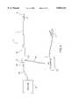
- FIG. 4is a schematic view of the electrosurgical device of FIG. 1 coupled to an electric generator and a source of vacuum;
- FIG. 5is a schematic illustration showing the electrosurgical device of FIG. 1 dissecting a left mammary artery from the inner thoracic wall in a thoracoscopic coronary artery bypass grafting procedure.
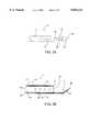
- FIG. 6Ais a side view of an electrosurgical device according to the invention in a further embodiment thereof.
- FIG. 6Bis a top view of a distal end of the electrosurgical device of FIG. 6A.
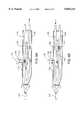
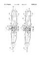
- FIGS. 7A-B, 8A-B, and 9A-Bare side cross-sections of a handle of the electrosurgical device of FIG. 6A, illustrating various embodiments of a switch for alternating between suction and irrigation.
- electrosurgical device 2includes an insulated shaft 4 electrically coupled to an electrode 6 and having a plurality of side holes 8 for evacuation of fluid from a surgical site.
- Shaft 4has a proximal end 10, a distal end 12 and an inner lumen 14 therebetween.
- Shaft 4is preferably a stainless steel tube having an outer diameter in the range of 2-8 mm, usually 3-5 mm, so as to fit within a cannula having an internal diameter in the range of 2-10 mm.
- Shaft 4can also be introduced directly through a percutaneous incision in the patient.
- Shaft 4has a length of about 10-40 cm so as to reach a target site in a body cavity, and to extend sufficiently out of the body cavity to facilitate easy manipulation of electrosurgical device 2.
- shaft 4is configured to reach an internal mammary artery in the thoracic cavity from a left lateral position in the chest, having a length between 20 cm and 30 cm, and preferably about 25 cm.
- Shaft 4has an interior surface 16 defined by lumen 14 and an exterior side surface 18.
- Lumen 14has a diameter slightly smaller than the outer diameter of shaft 4, or about 2-7 mm, depending on the shaft diameter, to provide a passage of maximum diameter for evacuation of smoke and other fluids.
- Exterior side surface 18 of shaft 4is covered by a layer of electrically insulating material 20, such as Teflon or nylon, so that electric current will not arc between an exposed portion of shaft 4 and the surrounding tissue.
- Electrosurgical device 2further includes a handle 26 attached to proximal end 10 of shaft 4.
- Handle 26includes a fluid connector such as a hose barb in communication with lumen 14 for coupling to either an irrigation or a vacuum source (not shown in FIG. 1).
- Handle 26further includes a conventional electrical connector 30, such as a banana plug, electrically coupled to shaft 4 and adapted for attachment to a source of electrical energy, such as an electrical generator (further details of the vacuum source and generator are described below with reference to FIG. 4).
- Handle 26may also include a finger switch (not shown) for selectively actuating the electrical generator or for shifting the frequency of the electric current so as to switch between coagulation and cutting.
- An additional switchmay be provided on handle 26 for selectively actuating suction or irrigation through lumen 14.
- electrode 6extends distally from distal end 12 of shaft 4 and has a distal portion bent at an angle of between about 5° and 60°, usually about 20°, relative to the longitudinal axis of shaft 4.
- Electrode 6has a wide, generally planar tip 24 forming a spatula configuration. This configuration facilitates viewing tip 24 through an endoscope in minimally invasive procedures.
- tip 24tapers inward in the distal direction to form a thin cutting surface with a curved distal end 25 for procedures that require precise incisions.
- Insulating material 20covers only a portion of electrode 6 so that at least planar tip 24 is exposed for cauterizing tissue.
- Electrode 6can comprise any of a variety of shapes, such as a pencil tip, L-hook, J-hook, tube, cutting loop, etc.
- electrode 6may be detachable by means of threads or other type of coupling mechanism, to allow interchanging electrodes of various types.
- shaft 4has a distally-oriented opening 27 in distal end 12 for the evacuation of smoke, blood, tissue particles and other debris from the surgical site.
- smokecan be continuously evacuated through side holes 8 disposed proximally from distal end 12, even when distal end 12 is pressed against tissue.
- Side holes 8have a substantially smaller diameter than shaft 4, preferably about 0.5-2.0 mm. This effectively prevents larger tissue particles that have been severed during cauterization from blocking or obstructing side holes 8 while allowing smoke and other fluids to pass through.
- Side holes 8each have a side wall 9 covered by a layer 28 of insulating material 20 so that electric current passing through shaft 4 will not jump or arc from an exposed portion of shaft 4 on side wall 9 into the surrounding tissue.
- a plurality of side holes 8, usually about sixteen in number,are positioned circumferentially around exterior side surface 18 and spaced axially along shaft 4 to enhance the evacuation of smoke and other fluids. It will, of course, be apparent to one of ordinary skill in the art that side holes 8 could have a variety of different arrangements around shaft 4, including axial, spiral, or circular configurations.
- FIGS. 3A and 3Billustrate an alternative embodiment of electrosurgical device 2a.
- the side holesare replaced with elongated slots 30.
- Slots 30generally extend in the axial direction and preferably have a small width, e.g. about 0.5-2.0 mm, to prevent tissue particles from passing through slots 30.
- Slots 30preferably have a length of about 5-10 mm in the axial direction to provide a large enough opening for the continuous evacuation of smoke.
- slots 30have side walls 32 that are covered by a layer 34 of insulating material 20 to ensure that shaft 4 remains completely insulated to protect the patient from electric current.
- electrosurgical device 2is coupled to a source of electrical energy such as a radio frequency generator 40 by coupling electrical connector 30 to one pole of generator 40 via an electrical line 42.
- a second electrode of generator 40may be provided in the form of a large plate electrode (which may or may not be grounded) for engagement with the skin of the patient (in the case of a unipolar system). In the case of a bipolar system, any suitable bipolar electrode may be used.
- a foot pedal switch 44is electrically connected to generator 42 for switching electric power to electrode 6 on and off.
- handle 26includes a button (not shown), coupled to electrical line 42, for actuating generator 40.
- a switchmay also be provided for selecting the frequency of the current for either coagulating or cutting, or two separate buttons may be provided, one for coagulation and one for cutting.
- electrosurgical device 2is coupled to a source of vacuum 50 by a suction line 52 attached to port 28.
- vacuum source 50is a standard vacuum canister found in most operating rooms, which effectively evacuates fluid using standard vacuum pressures and flows specified for operating rooms.
- Port 28may also be attached to a source of liquid, such as saline, for irrigation of an interior portion of the patient's body. This may be useful in clearing away debris from the area at which electrode 6 is operating to provide the surgeon with relatively unobstructed visibility.
- handle 26may include a second port for attachment to the fluid source so that both of these operations are available to the surgeon during the operation.
- a foot pedal or handle-mounted switchmay also be provided to allow the operator to selectively actuate suction or irrigation.
- Either or both of these switchesmay be of the type which allow selectable variation of the vacuum pressure or irrigation flow rate.
- a sliding vent on handle 26 in communication with lumen 14would allow selectable diversion of the vacuum outside of lumen 14 to vary the strength of vacuum exerted through lumen 14.
- An electronic, slidable or rotatable valve on handle 26, suction line 52, or vacuum source 50may also be used.
- the vacuum switchmay be electrically coupled to the electrocautery switch so that vacuum is automatically turned on when electrocautery is turned on, and turned off when electrocautery is turned off.
- shaft 4is machined using conventional machining techniques.
- Shaft 4is constructed out of a conductive material, preferably a biocompatible metal such as stainless steel or tungsten carbide.
- Side holes 8are then drilled into shaft 4.
- Electrode 6is attached to distal end 12 of shaft 4 by welding or other known technique.
- Electrode 6is then masked, and shaft 4 is sprayed with an electrically insulating powdered polymer 20, such as polyolefin, to completely coat the exterior of shaft 4, sidewalls 26 of side holes 8, and at least the end portions of the inner wall of shaft 4 around lumen 14.
- a second layer of poly tetrafluoroethylene (PTFE)may be sprayed over or together with the polyolefin.
- the layer(s) of insulating materialare then cured by heating shaft 4 in an oven.
- Handle 26may then be mounted to the proximal end of shaft 4 by threaded connection, press-fit, set screw, adhesive bonding, or other conventional method.
- shaft 4may be dipped into a container of electrically insulating liquefied polymer, such as nylon or Teflon, which leaves a thin insulating coating on all surfaces of shaft 4, including side walls 26 of side holes 8.
- the shaftis dipped repeatedly until a suitable thickness of the coating has adhered to shaft 4.
- the insulating material 20is then solidified, preferably, by curing at room temperature.
- a sheath(not shown) of ABS or other suitable plastic may be mounted coaxially over shaft 4.
- the sheathmay be axially slidable relative to the shaft to allow the sheath to be extended beyond the distal end of the shaft so as to surround electrode tip 24.
- the sheathmay be used to protect the electrode tip when not in use, and may also function as a suction tube that may be slid beyond the electrode tip to evacuate fluids from the surgical site.
- the sheathmay include side holes in communication with the side holes in shaft 4.
- the inventionmay be used in a variety of surgical procedures within body cavities.
- the inventionis particularly well-adapted for dissecting an internal mammary artery away from the inner thoracic wall in a coronary artery bypass grafting procedure.
- FIG. 5A method for preparing an internal mammary artery for a coronary artery bypass grafting procedure according to the invention will now be described in conjunction with FIG. 5.
- the patient undergoing the procedureis placed under general anesthesia and prepared in a conventional manner for cardiac surgery.
- a plurality of access trocar sleeves 52, 54, 56will be positioned in percutaneous intercostal penetrations of the patient's chest for introduction of electrosurgical device 2 and other surgical instruments.
- Trocar sleeves 52,54,56will be positioned within intercostal spaces in the left lateral chest of the patient, generally within the second, third, fourth, fifth, sixth or seventh intercostal spaces.
- electrosurgical device 2will preferably be introduced through a percutaneous intercostal penetration in either the third or fourth intercostal space.
- Suitable trocar sleevesare available from United States Surgical Corp. of Norwalk, Conn., under the brand name "Thoracoport". Although trocar sleeves are described as the preferred method of introducing instruments into the thoracic cavity, electrosurgical device 2 can be introduced directly through a small intercostal incision in the patient's chest. Trocar sleeves are preferred, however, to provide an open passage into the thoracic cavity and to protect adjacent tissue from injury.
- Mammary artery Mis located on the anterior side of the inner chest wall just lateral to the sternum.
- a viewing scope 60is introduced through trocar sleeve 56 to a position suitable for viewing artery M on the inner chest wall.
- Viewing scope 60can be any conventional viewing scope such as an endoscope, laparoscope, or thoracoscope, which typically consist of an elongated tube 62 containing a lens system and an eyepiece or camera mount 64 at the proximal end of the tube 62.
- a small video camera 65is preferably attached to the camera mount and connected to a video monitor to provide a video image of the procedure.
- the viewing scopemay also have an articulating tip (not shown) that can be deflected or rotated by manipulating an actuator on a proximal end of tube 62.
- This type of scopeis commercially available from Baxter Healthcare Corp. of Deerfield, Ill.
- the left lungwill be collapsed to facilitate viewing of the operation.
- a double lumen endotracheal tubemay be used for this purpose.
- distal end 12 of shaft 4is introduced through trocar sleeve 52 and electrode 6 is positioned adjacent internal mammary artery M, by positioning distal end 12 anteriorly and rightward from trocar sleeve 52 under visualization with viewing scope 60.
- the vacuum sourceis started so that a continuous vacuum is created through lumen 14 of shaft 4.
- the surgeonthen actuates the electric current by pressing down on foot pedal 44 and gradually dissects mammary artery M free from the surrounding tissues of the inside surface of the chest wall, progressing from near its origin at the subclavian artery towards its bifurcation near the xyphoid process.
- the spatula shape of electrode 6facilitates dissection of artery M from the chest wall and allows the surgeon to view distal tip 24 through scope 60.
- the smoke generated from cutting the tissues of the inner chest wall around artery Mis continuously evacuated through side holes 8.
- the surgeonmay urge electrode 6 into the surrounding tissue until distal end 12 of shaft 4 abuts against this tissue, thereby blocking distal opening 27.
- the surgeonmay also exchange vacuum line 52 with an irrigation line in order to deliver fluid through lumen 24 to wash away fluids, tissue or other debris from the site. Bleeding branches of artery M created during the dissection may also be cauterized with electrode 6.
- the desired segment of artery Mmay be ligated, divided and prepared for anastomosis.
- the free end of the dissected artery Mmay be sutured to a diseased coronary artery on the heart to bypass an occluded region in the coronary artery.
- the devices and techniques described in commonly assigned patent application Ser. No. 08/282,192, filed Jul. 28, 1994, which is incorporated herein by referenceare utilized to induce cardioplegic arrest and establish cardiopulmonary bypass without performing a median sternotomy.
- Thoracoscopic techniques for performing an IMA-coronary artery anastomosisare described in U.S. Pat. No. 5,501,698, which has been incorporated herein by reference.
- electrocautery probe 102includes, as in other embodiments, an insulated shaft 104, an electrode tip 106 at the distal end of the shaft, and a handle 108 attached to the proximal end of the shaft.
- shaft 104includes side holes 110 near its distal end for evacuation of smoke from the surgical area, as described above.
- Electrode tip 106is covered with an insulative coating, allowing electrode tip 106 to extend a significant distance distally from the distal end of shaft 104 to facilitate better visibility of the tip and its interaction with tissue, while preventing unintentional burning of tissue due to incidental contact.
- Electrode tip 106is preferably angled away from the longitudinal axis of shaft 104 by an angle in a range of about 10 to 60 degrees to facilitate thoracoscopic approaches to the mammary artery via access ports in the anterior or lateral sides of the chest.
- Electrode tip 106is preferably 10-15 mm in length from the distal end of shaft 104, and has a transverse width (or diameter) of about 1.5-4.5 mm.
- Electrode tip 106, shaft 104, and handle 110may be otherwise designed and constructed similarly to the embodiments described above and shown in FIGS. 1-6.
- Handle 108includes a cutting switch 112 and coagulation switch 114 (for changing the frequency of radiofrequency current delivered to electrode 106, as described above), and an alternating continuous suction/irrigation switch 116.
- suction/irrigation switch 116comprises a button 118 movably mounted to handle 108 and biased outward by a spring 120.
- a suction tube 122 and irrigation tube 124extend through handle 108 and are both connected to the lumen 126 within shaft 104.
- Suction tube 122 and irrigation tube 124are made of a soft polymer such as Tygon or silicone with a durometer in the range of 35-70 Shore A.
- Button 118has a shaft 128 extending into handle 108 with a foot 130 at its inner end extending transversely to shaft 128 and disposed between suction tube 122 and irrigation tube 124.
- foot 130pinches irrigation tube 124 closed, blocking flow of irrigation fluid to lumen 126, while vacuum tube 122 remains open, allowing suction to be exerted through lumen 126.
- vacuum tube 122is pinched closed, stopping vacuum through the lumen 126, while opening irrigation tube 124 to initiate the flow of irrigation fluid through the lumen.
- switch 116again includes a button 118 having a shaft 128 extending into handle 108, with a spring 120 biasing button 118 outward.
- a rocker arm 132is pivotably mounted to handle 108 by a first pin 134, and pivotably coupled to shaft 128 by a second pin 136.
- a first cross-member 138is mounted transversely to rocker arm 132 on a first end thereof and is disposed between suction tube 122 and irrigation tube 124.
- a second cross-member 140is mounted transversely to rocker arm 132 on a second end thereof and is disposed laterally of irrigation tube 124.
- a stop 142is mounted to handle 108, irrigation tube 124 extending through a gap between second cross-member 140 and stop 142.
- Irrigation tube 124is pinched closed, preventing flow of irrigation fluid, while suction tube 122 is open, allowing suction to be applied through lumen 126.
- suction tube 122is pinched closed between second cross-member 140 and stop 142, stopping suction, while opening irrigation tube 124 to allow flow of irrigation fluid through lumen 126.
- switch 116again comprises a button 118, shaft 128, and biasing spring 120.
- alternation of suction and irrigationdoes not rely upon pinching off of soft tubes as in previous embodiments.
- a manifold 144is attached to the inner end of shaft 128, and includes a Y-shaped fluid pathway with a suction inlet 146, an irrigation fluid inlet 148, and an outlet 150.
- Manifold 144is movably mounted within a manifold housing 152.
- Suction tube 122is connected to manifold housing 152 at a suction port 154 and irrigation tube 124 is connected to manifold housing 152 at an irrigation port 156.
- Manifold 144is movable between an upper position (FIG. 9A) wherein suction inlet 146 is aligned with suction port 154, and a lower position (FIG. 9B) wherein irrigation fluid inlet 148 is aligned with irrigation port 156.
- outlet 150is aligned with an outlet port 168 in manifold housing 152, to which lumen 126 in shaft 104 is fluidly connected by means of an outlet tube 160.
- suction inlet 146is aligned with suction port 154 allowing suction to be applied through outlet tube 160 and shaft 104.
- irrigation fluid inlet 148is not aligned with irrigation port 156, preventing the flow of irrigation fluid.
- button 118is depressed as in FIG. 9B, irrigation fluid inlet 148 is aligned with irrigation port 156, allowing irrigation fluid to flow through outlet tube 160 and shaft 104, while stopping suction.
Landscapes
- Health & Medical Sciences (AREA)
- Heart & Thoracic Surgery (AREA)
- Engineering & Computer Science (AREA)
- Life Sciences & Earth Sciences (AREA)
- Animal Behavior & Ethology (AREA)
- Veterinary Medicine (AREA)
- Public Health (AREA)
- Biomedical Technology (AREA)
- General Health & Medical Sciences (AREA)
- Anesthesiology (AREA)
- Hematology (AREA)
- Vascular Medicine (AREA)
- Surgery (AREA)
- Pulmonology (AREA)
- Physics & Mathematics (AREA)
- Plasma & Fusion (AREA)
- Nuclear Medicine, Radiotherapy & Molecular Imaging (AREA)
- Otolaryngology (AREA)
- Medical Informatics (AREA)
- Molecular Biology (AREA)
- Surgical Instruments (AREA)
Abstract
Description
CROSS-REFERENCE TO RELATED APPLICATION
This is a continuation-in-part of application Ser. No. 08/336,359, filed Nov. 8, 1994 (now abandoned), which is incorporated herein by reference for all purposes.
This invention relates generally to devices for less-invasive surgical procedures, and more specifically to an electrosurgical device for cauterizing tissue and evacuating fluid from a surgical site in less-invasive surgical procedures.
Electrosurgical devices are used for coagulating fluids and cauterizing tissue structures in various types of less-invasive surgical procedures. These devices commonly comprise a shaft having an electrosurgical electrode extending from its distal end. The electrode is connected to a source of electricity, such as a high frequency generator, for supplying a high density current to the electrode. The current at the electrode jumps across an air gap or arcs into the target tissue structure and then travels through the patient into a grounding pad or cable attached to the patient's skin. The heat generated by the current in the tissue structure causes coagulation of fluids or cauterization of tissue, depending upon the current level. In order to confine current to the electrode tip, the shaft is made of an electrically insulating material, or if conductive, the shaft is covered with an electrically insulating material such as a shrink-wrapped plastic film.
In using electrosurgical devices, whether for coagulating or cutting tissue, a large amount of smoke is generated. This smoke can obstruct or completely block the surgeons' field of vision during the operation. In addition, the smoke contains aerosolized and vaporized organic material, carbon particles and viable viral particles. These potentially infectious and/or carcinogenic materials can be inhaled by the patient or the operating team. The odor of cauterized tissue can also be irritating to the operating team.
In laparoscopic and thoracoscopic procedures, the smoke created during electrocautery can be particularly problematic. Because such procedures are carried out through small ports, trocars, or punctures in the abdominal or chest wall without making large incisions, the smoke created by electrocautery cannot easily escape from the body cavity. This can produce extremely poor visibility in the body cavity, adding further difficulty to the already challenging task of visualization in such procedures.
To solve the problems associated with the smoke produced in electrocautery, some known electrocautery devices employ suction means to withdraw from the body cavity the smoke generated at the electrode tip. In an exemplary design, a lumen extends through the shaft of the device to a distally-oriented opening at the distal end. The proximal end of the lumen is coupled to a vacuum device that sucks the smoke through the lumen and into a waste receptacle.
Known devices having smoke-evacuation capability suffer, however, from a variety of problems. When cutting tissue, the distal end of the shaft may often be pressed against the tissue, obstructing the opening in the distal end and inhibiting evacuation of smoke. Severed or loose tissue particles will often get sucked against the distal end of the tube thereby obstructing smoke evacuation through the opening. Smaller tissue particles that pass through the distal opening may clog the inner lumen further up the shaft.
What are needed, therefore, are electrosurgical devices and methods of using such devices which are adapted for cauterizing tissue and for effectively evacuating the smoke generated during cauterization. The devices and methods should be capable of continuously evacuating smoke throughout a surgical procedure without becoming clogged by tissue and other debris around the operating site. The devices should be configured for use in various surgical procedures, but should be particularly well-adapted for use in thoracoscopic and laparoscopic procedures.
The present invention provides an electrosurgical device and method of use thereof for cauterizing tissue at a surgical site and evacuating fluid from the surgical site. The device is configured to maintain a substantially open fluid path between its distal and proximal ends so that fluid, such as smoke, can be continuously evacuated throughout the procedure. The device is configured for introduction through a small percutaneous penetration in the patent, and is particularly suited for introduction through an intercostal space in thoracoscopic surgical procedures.
In one aspect of the invention, an electrocautery device comprises a shaft having proximal and distal ends, an inner lumen therebetween, and an opening at the distal end in communication with the inner lumen. An electrode is attached to the distal end of the shaft and extends distally therefrom. A handle is attached to the proximal end of the shaft, and a connector is mounted on the handle that is adapted for connection to a source of electricity. A conductor extends between the connector and the electrode for conducting electricity to the electrode for cauterizing tissue. An irrigation port is provided on the handle that is fluidly connected to the inner lumen and adapted for connection to a source of irrigation fluid. A suction port is also provided on the handle, is fluidly connected to the inner lumen and is adapted for connection to a source of suction. A switch on the handle is movable between a first position and a second position, wherein, in the first position, the irrigation port is fluidly isolated from the inner lumen and the suction port is in fluid communication with the inner lumen, and in the second position, the suction port is fluidly isolated from the inner lumen and the irrigation port is in fluid communication with the inner lumen.
In a further embodiment, the electrosurgery device has an insulated conductive shaft that has a proximal end adapted for electrically coupling the shaft to a source of electrical energy. An electrode is coupled to the distal end of the shaft through which electric current can be delivered for cauterizing tissue or coagulating fluids. The shaft has an inner lumen between the proximal and distal ends that may be fluidly coupled to a source of vacuum at the proximal end. The shaft further includes at least one insulated side hole near the distal end in fluid communication with the inner lumen. With this configuration, fluid such as smoke generated from cauterizing or coagulating can be continuously evacuated through the side hole and the inner lumen of the shaft without obstruction.
In one embodiment, the device includes a plurality of insulated side holes in the wall of the shaft near its distal end, each in communication with the inner lumen. The exterior of the shaft is covered with an electrically insulating material. The side holes have side walls also covered with the insulating material to prevent an electric arc from being generated between the side holes and the surrounding tissue. The side holes are spaced proximally from the distal end of the shaft so that fluid can be evacuated even when the distal end of the shaft is pressed against a tissue or otherwise obstructed. Preferably, the diameter of the side holes is substantially smaller than the diameter of the shaft so that smoke may pass through, but larger tissue particles may not. This inhibits large tissue particles from obstructing or blocking the lumen in the shaft. The side holes may be round, rectangular slots, ovals, or other shapes.
The device further includes switch means coupled to the proximal end of the shaft, for selectively connecting the electricity source to the shaft (and therefore the electrode). The switch means may comprise a button mounted to the proximal end of the shaft, or a foot pedal switch.
Preferably, the shaft is made of a conductive material such as stainless steel so that the shaft itself conducts electrical current from the generator to the electrode. The shaft may be tubular so that the diameter of the inner lumen is maximized to provide a large fluid passage through the inner lumen. In this way, tissue particles that are sucked into the shaft are likely to pass completely through the lumen rather than obstructing it.
In a preferred configuration, the electrode and the distal end of the shaft are configured for introduction into the thoracic cavity through a small incision or puncture in an intercostal space. The diameter of the shaft, or largest transverse dimension of the electrode, is usually less than 12 mm, and preferably about 5 mm. The electrode has a planar or large-curvature surface forming a spatula-shaped tip. This configuration allows the surgeon to see the electrode more clearly within the body cavity with conventional endoscopic visualization devices, such as an endoscope. In an exemplary embodiment, the electrode is configured for dissecting an internal mammary artery away from the inner thoracic wall to expose the mammary artery for use in a coronary artery bypass grafting procedure.
The electrocautery device is preferably constructed by selecting a tubular shaft of a biocompatible metal such as stainless steel of the appropriate length and diameter. A plurality of side holes are drilled in the wall of the shaft near the distal end. An electrode is then formed at the distal end of the shaft, usually by welding a steel tip of the desired shape to the distal end of the shaft. The shaft is then coated by a sprayed powder coating process using an electrically-insulating polymer such as polyolefin with a poly tetrafluoroethylene (PTFE) coating, so that the material coats the exterior of the shaft and the sidewalls of the side holes. The insulating material is allowed to cure or solidify, and the distal tip of the electrode is then stripped of the insulating material to expose that portion of the electrode to be used for cauterization and coagulation. Alternatively, the electrode tip may be masked during the coating process. An insulating handle may be mounted to the proximal end of the shaft, to which an electrical switch and connector may be mounted, and to which a hose barb or other fluid connector mounted for connection to a vacuum source. In an alternative process, the shaft is coated by dipping the shaft into a container of liquefied insulating material so that the exterior surface and sidewalls of the side holes are covered. The material is then allowed to solidify and cure until hard.
One advantage of spray coating the shaft with insulating material is that the coating of insulation is formed around the shaft. This coating is generally less susceptible to tearing or damage than a shrink wrapped plastic film when the shaft is introduced through a percutaneous incision or cannula. In addition, the spray coating ensures that the side walls of the side holes are insulated so that an electric current does not arc from exposed portions of the shaft on the hole side walls.
A further understanding of the nature and advantages of the invention may be realized by reference to the remaining portions of the specification and the drawings.
FIG. 1 is a side view of an electrosurgical device according to the principles of the present invention;
FIG. 2A is a top view of a distal end of the electrosurgical device of FIG. 1;
FIG. 2B is a side cross-sectional view of a distal end of the electrosurgical device of FIG. 1;
FIG. 3A is a top view of a distal end of an electrosurgical device according to the invention in an alternative embodiment;
FIG. 3B is a side cross-sectional view of the distal end of the electrosurgical device of FIG. 3A;
FIG. 4 is a schematic view of the electrosurgical device of FIG. 1 coupled to an electric generator and a source of vacuum; and
FIG. 5 is a schematic illustration showing the electrosurgical device of FIG. 1 dissecting a left mammary artery from the inner thoracic wall in a thoracoscopic coronary artery bypass grafting procedure.
FIG. 6A is a side view of an electrosurgical device according to the invention in a further embodiment thereof.
FIG. 6B is a top view of a distal end of the electrosurgical device of FIG. 6A.
FIGS. 7A-B, 8A-B, and 9A-B are side cross-sections of a handle of the electrosurgical device of FIG. 6A, illustrating various embodiments of a switch for alternating between suction and irrigation.
Referring to the drawings, anelectrosurgical device 2 is illustrated according to the principles of the present invention. Referring to FIG. 1,electrosurgical device 2 includes aninsulated shaft 4 electrically coupled to anelectrode 6 and having a plurality ofside holes 8 for evacuation of fluid from a surgical site.
Referring to FIGS. 2A and 2B,electrode 6 extends distally fromdistal end 12 ofshaft 4 and has a distal portion bent at an angle of between about 5° and 60°, usually about 20°, relative to the longitudinal axis ofshaft 4.Electrode 6 has a wide, generallyplanar tip 24 forming a spatula configuration. This configuration facilitatesviewing tip 24 through an endoscope in minimally invasive procedures. Preferably,tip 24 tapers inward in the distal direction to form a thin cutting surface with a curveddistal end 25 for procedures that require precise incisions. Insulatingmaterial 20 covers only a portion ofelectrode 6 so that at leastplanar tip 24 is exposed for cauterizing tissue. It will be noted that the invention is not limited to the spatula-shaped electrode described above and shown in the figures.Electrode 6 can comprise any of a variety of shapes, such as a pencil tip, L-hook, J-hook, tube, cutting loop, etc. In addition,electrode 6 may be detachable by means of threads or other type of coupling mechanism, to allow interchanging electrodes of various types.
As shown in FIG. 2B,shaft 4 has a distally-orientedopening 27 indistal end 12 for the evacuation of smoke, blood, tissue particles and other debris from the surgical site. However, should distal opening 27 become obstructed or blocked during the surgical procedure, smoke can be continuously evacuated throughside holes 8 disposed proximally fromdistal end 12, even whendistal end 12 is pressed against tissue. Side holes 8 have a substantially smaller diameter thanshaft 4, preferably about 0.5-2.0 mm. This effectively prevents larger tissue particles that have been severed during cauterization from blocking or obstructing side holes 8 while allowing smoke and other fluids to pass through.
Side holes 8 each have aside wall 9 covered by alayer 28 of insulatingmaterial 20 so that electric current passing throughshaft 4 will not jump or arc from an exposed portion ofshaft 4 onside wall 9 into the surrounding tissue. In a preferred configuration, a plurality ofside holes 8, usually about sixteen in number, are positioned circumferentially aroundexterior side surface 18 and spaced axially alongshaft 4 to enhance the evacuation of smoke and other fluids. It will, of course, be apparent to one of ordinary skill in the art that side holes 8 could have a variety of different arrangements aroundshaft 4, including axial, spiral, or circular configurations.
FIGS. 3A and 3B illustrate an alternative embodiment ofelectrosurgical device 2a. In this embodiment, the side holes are replaced withelongated slots 30.Slots 30 generally extend in the axial direction and preferably have a small width, e.g. about 0.5-2.0 mm, to prevent tissue particles from passing throughslots 30.Slots 30 preferably have a length of about 5-10 mm in the axial direction to provide a large enough opening for the continuous evacuation of smoke. As shown in FIG. 3B,slots 30 haveside walls 32 that are covered by alayer 34 of insulatingmaterial 20 to ensure thatshaft 4 remains completely insulated to protect the patient from electric current.
Referring to FIG. 4,electrosurgical device 2 is coupled to a source of electrical energy such as aradio frequency generator 40 by couplingelectrical connector 30 to one pole ofgenerator 40 via anelectrical line 42. A second electrode ofgenerator 40 may be provided in the form of a large plate electrode (which may or may not be grounded) for engagement with the skin of the patient (in the case of a unipolar system). In the case of a bipolar system, any suitable bipolar electrode may be used.
In one embodiment, afoot pedal switch 44 is electrically connected togenerator 42 for switching electric power toelectrode 6 on and off. In another embodiment, handle 26 includes a button (not shown), coupled toelectrical line 42, for actuatinggenerator 40. A switch may also be provided for selecting the frequency of the current for either coagulating or cutting, or two separate buttons may be provided, one for coagulation and one for cutting.
As shown in FIG. 4,electrosurgical device 2 is coupled to a source ofvacuum 50 by asuction line 52 attached toport 28. Preferably,vacuum source 50 is a standard vacuum canister found in most operating rooms, which effectively evacuates fluid using standard vacuum pressures and flows specified for operating rooms.Port 28 may also be attached to a source of liquid, such as saline, for irrigation of an interior portion of the patient's body. This may be useful in clearing away debris from the area at whichelectrode 6 is operating to provide the surgeon with relatively unobstructed visibility. Alternatively, handle 26 may include a second port for attachment to the fluid source so that both of these operations are available to the surgeon during the operation. A foot pedal or handle-mounted switch may also be provided to allow the operator to selectively actuate suction or irrigation. Either or both of these switches may be of the type which allow selectable variation of the vacuum pressure or irrigation flow rate. For example, a sliding vent onhandle 26 in communication withlumen 14 would allow selectable diversion of the vacuum outside oflumen 14 to vary the strength of vacuum exerted throughlumen 14. An electronic, slidable or rotatable valve onhandle 26,suction line 52, orvacuum source 50 may also be used. Additionally, the vacuum switch may be electrically coupled to the electrocautery switch so that vacuum is automatically turned on when electrocautery is turned on, and turned off when electrocautery is turned off.
To manufactureelectrosurgical device 2,shaft 4 is machined using conventional machining techniques.Shaft 4 is constructed out of a conductive material, preferably a biocompatible metal such as stainless steel or tungsten carbide. Side holes 8 are then drilled intoshaft 4.Electrode 6 is attached todistal end 12 ofshaft 4 by welding or other known technique.Electrode 6 is then masked, andshaft 4 is sprayed with an electrically insulatingpowdered polymer 20, such as polyolefin, to completely coat the exterior ofshaft 4, sidewalls 26 ofside holes 8, and at least the end portions of the inner wall ofshaft 4 aroundlumen 14. A second layer of poly tetrafluoroethylene (PTFE) may be sprayed over or together with the polyolefin. The layer(s) of insulating material are then cured byheating shaft 4 in an oven.Handle 26 may then be mounted to the proximal end ofshaft 4 by threaded connection, press-fit, set screw, adhesive bonding, or other conventional method.
In an alternative process,shaft 4 may be dipped into a container of electrically insulating liquefied polymer, such as nylon or Teflon, which leaves a thin insulating coating on all surfaces ofshaft 4, includingside walls 26 of side holes 8. The shaft is dipped repeatedly until a suitable thickness of the coating has adhered toshaft 4. The insulatingmaterial 20 is then solidified, preferably, by curing at room temperature.
Alternatively, a sheath (not shown) of ABS or other suitable plastic may be mounted coaxially overshaft 4. The sheath may be axially slidable relative to the shaft to allow the sheath to be extended beyond the distal end of the shaft so as to surroundelectrode tip 24. In this way, the sheath may be used to protect the electrode tip when not in use, and may also function as a suction tube that may be slid beyond the electrode tip to evacuate fluids from the surgical site. The sheath may include side holes in communication with the side holes inshaft 4.
The invention may be used in a variety of surgical procedures within body cavities. The invention is particularly well-adapted for dissecting an internal mammary artery away from the inner thoracic wall in a coronary artery bypass grafting procedure.
A method for preparing an internal mammary artery for a coronary artery bypass grafting procedure according to the invention will now be described in conjunction with FIG. 5. A more complete description of instruments and techniques for performing thoracoscopic coronary artery bypass grafting can be found in commonly assigned U.S. Pat. Nos. 5,452,733 and 5,501,698, which are incorporated herein by reference. The patient undergoing the procedure is placed under general anesthesia and prepared in a conventional manner for cardiac surgery. A plurality ofaccess trocar sleeves electrosurgical device 2 and other surgical instruments.Trocar sleeves electrosurgical device 2 will preferably be introduced through a percutaneous intercostal penetration in either the third or fourth intercostal space. Suitable trocar sleeves are available from United States Surgical Corp. of Norwalk, Conn., under the brand name "Thoracoport". Although trocar sleeves are described as the preferred method of introducing instruments into the thoracic cavity,electrosurgical device 2 can be introduced directly through a small intercostal incision in the patient's chest. Trocar sleeves are preferred, however, to provide an open passage into the thoracic cavity and to protect adjacent tissue from injury.
The method of the invention will be described in reference to grafting the left internal mammary artery M to the left anterior descending coronary artery C, as shown in FIG. 5. Mammary artery M is located on the anterior side of the inner chest wall just lateral to the sternum. Aviewing scope 60 is introduced throughtrocar sleeve 56 to a position suitable for viewing artery M on the inner chest wall.Viewing scope 60 can be any conventional viewing scope such as an endoscope, laparoscope, or thoracoscope, which typically consist of an elongated tube 62 containing a lens system and an eyepiece orcamera mount 64 at the proximal end of the tube 62. Asmall video camera 65 is preferably attached to the camera mount and connected to a video monitor to provide a video image of the procedure. The viewing scope may also have an articulating tip (not shown) that can be deflected or rotated by manipulating an actuator on a proximal end of tube 62. This type of scope is commercially available from Baxter Healthcare Corp. of Deerfield, Ill.
Before the anastomosis procedure begins, the left lung will be collapsed to facilitate viewing of the operation. A double lumen endotracheal tube may be used for this purpose. After the lung is collapsed,distal end 12 ofshaft 4 is introduced throughtrocar sleeve 52 andelectrode 6 is positioned adjacent internal mammary artery M, by positioningdistal end 12 anteriorly and rightward fromtrocar sleeve 52 under visualization withviewing scope 60. The vacuum source is started so that a continuous vacuum is created throughlumen 14 ofshaft 4. The surgeon then actuates the electric current by pressing down onfoot pedal 44 and gradually dissects mammary artery M free from the surrounding tissues of the inside surface of the chest wall, progressing from near its origin at the subclavian artery towards its bifurcation near the xyphoid process. The spatula shape ofelectrode 6 facilitates dissection of artery M from the chest wall and allows the surgeon to viewdistal tip 24 throughscope 60.
The smoke generated from cutting the tissues of the inner chest wall around artery M is continuously evacuated through side holes 8. During the procedure, the surgeon may urgeelectrode 6 into the surrounding tissue untildistal end 12 ofshaft 4 abuts against this tissue, thereby blockingdistal opening 27. Side holes 8, however, are sufficiently proximal ofdistal end 12 to remain substantially unobstructed during the entire procedure. The surgeon may also exchangevacuum line 52 with an irrigation line in order to deliver fluid throughlumen 24 to wash away fluids, tissue or other debris from the site. Bleeding branches of artery M created during the dissection may also be cauterized withelectrode 6.
Once the desired segment of artery M has been dissected from the inner thoracic wall, it may be ligated, divided and prepared for anastomosis. After initiating cardiopulmonary bypass and inducing cardioplegic arrest, the free end of the dissected artery M may be sutured to a diseased coronary artery on the heart to bypass an occluded region in the coronary artery. Preferably, the devices and techniques described in commonly assigned patent application Ser. No. 08/282,192, filed Jul. 28, 1994, which is incorporated herein by reference, are utilized to induce cardioplegic arrest and establish cardiopulmonary bypass without performing a median sternotomy. Thoracoscopic techniques for performing an IMA-coronary artery anastomosis are described in U.S. Pat. No. 5,501,698, which has been incorporated herein by reference.
Further embodiments of the electrocautery probe of the invention are illustrated in FIGS. 6-9. In these embodiments, as shown in FIGS. 6A-B,electrocautery probe 102 includes, as in other embodiments, aninsulated shaft 104, anelectrode tip 106 at the distal end of the shaft, and ahandle 108 attached to the proximal end of the shaft. Preferably,shaft 104 includes side holes 110 near its distal end for evacuation of smoke from the surgical area, as described above. Aproximal portion 107 ofelectrode tip 106 is covered with an insulative coating, allowingelectrode tip 106 to extend a significant distance distally from the distal end ofshaft 104 to facilitate better visibility of the tip and its interaction with tissue, while preventing unintentional burning of tissue due to incidental contact.Electrode tip 106 is preferably angled away from the longitudinal axis ofshaft 104 by an angle in a range of about 10 to 60 degrees to facilitate thoracoscopic approaches to the mammary artery via access ports in the anterior or lateral sides of the chest.Electrode tip 106 is preferably 10-15 mm in length from the distal end ofshaft 104, and has a transverse width (or diameter) of about 1.5-4.5 mm.Electrode tip 106,shaft 104, and handle 110 may be otherwise designed and constructed similarly to the embodiments described above and shown in FIGS. 1-6.
Handle 108 includes a cuttingswitch 112 and coagulation switch 114 (for changing the frequency of radiofrequency current delivered toelectrode 106, as described above), and an alternating continuous suction/irrigation switch 116. Various embodiments of suction/irrigation switch 116 are illustrated in FIGS. 7-9. In the embodiment of FIGS. 7A-B, suction/irrigation switch 116 comprises abutton 118 movably mounted to handle 108 and biased outward by aspring 120. Asuction tube 122 andirrigation tube 124 extend throughhandle 108 and are both connected to thelumen 126 withinshaft 104.Suction tube 122 andirrigation tube 124 are made of a soft polymer such as Tygon or silicone with a durometer in the range of 35-70Shore A. Button 118 has ashaft 128 extending intohandle 108 with afoot 130 at its inner end extending transversely toshaft 128 and disposed betweensuction tube 122 andirrigation tube 124. Inswitch 116's normally outward position of FIG. 7A, foot 130 pinchesirrigation tube 124 closed, blocking flow of irrigation fluid to lumen 126, whilevacuum tube 122 remains open, allowing suction to be exerted throughlumen 126. When the operator pushes button inward as in FIG. 7B,vacuum tube 122 is pinched closed, stopping vacuum through thelumen 126, while openingirrigation tube 124 to initiate the flow of irrigation fluid through the lumen. In this way, suction is automatically discontinued when irrigation is applied, thereby avoiding the evacuation of irrigation fluid before it has reached the surgical site. Moreover, no materials or moving parts other thantubes
In an alternative embodiment, shown in FIGS. 8A-B, switch 116 again includes abutton 118 having ashaft 128 extending intohandle 108, with aspring 120biasing button 118 outward. Arocker arm 132 is pivotably mounted to handle 108 by afirst pin 134, and pivotably coupled toshaft 128 by asecond pin 136. Afirst cross-member 138 is mounted transversely torocker arm 132 on a first end thereof and is disposed betweensuction tube 122 andirrigation tube 124. Asecond cross-member 140 is mounted transversely torocker arm 132 on a second end thereof and is disposed laterally ofirrigation tube 124. Opposite second cross-member 140 astop 142 is mounted to handle 108,irrigation tube 124 extending through a gap between second cross-member 140 and stop 142. In this way, whenbutton 118 is in its normally outward position of FIG. 8A,Irrigation tube 124 is pinched closed, preventing flow of irrigation fluid, whilesuction tube 122 is open, allowing suction to be applied throughlumen 126. Whenbutton 118 is depressed as in FIG. 8B,suction tube 122 is pinched closed between second cross-member 140 and stop 142, stopping suction, while openingirrigation tube 124 to allow flow of irrigation fluid throughlumen 126.
In a further embodiment, shown in FIGS. 9A-9B, switch 116 again comprises abutton 118,shaft 128, and biasingspring 120. In this embodiment, alternation of suction and irrigation does not rely upon pinching off of soft tubes as in previous embodiments. A manifold 144 is attached to the inner end ofshaft 128, and includes a Y-shaped fluid pathway with asuction inlet 146, anirrigation fluid inlet 148, and anoutlet 150.Manifold 144 is movably mounted within amanifold housing 152.Suction tube 122 is connected tomanifold housing 152 at asuction port 154 andirrigation tube 124 is connected tomanifold housing 152 at an irrigation port 156.Manifold 144 is movable between an upper position (FIG. 9A) whereinsuction inlet 146 is aligned withsuction port 154, and a lower position (FIG. 9B) whereinirrigation fluid inlet 148 is aligned with irrigation port 156. In either position,outlet 150 is aligned with anoutlet port 168 inmanifold housing 152, to whichlumen 126 inshaft 104 is fluidly connected by means of anoutlet tube 160. In operation, in the normally outward position of FIG. 9A,suction inlet 146 is aligned withsuction port 154 allowing suction to be applied throughoutlet tube 160 andshaft 104. In this position,irrigation fluid inlet 148 is not aligned with irrigation port 156, preventing the flow of irrigation fluid. Whenbutton 118 is depressed as in FIG. 9B,irrigation fluid inlet 148 is aligned with irrigation port 156, allowing irrigation fluid to flow throughoutlet tube 160 andshaft 104, while stopping suction.
While the above is a complete description of the preferred embodiments of the invention, various alternatives, modifications and equivalents may be used. Therefore, the above description should not be taken as limiting the scope of the invention, which is defined by the appended claims.
Claims (28)
1. A surgical suction and irrigation device comprising:
a shaft having proximal and distal ends and an inner lumen therebetween, and an opening at the distal end in communication with the inner lumen;
a handle attached to the proximal end of the shaft;
an irrigation port on the handle fluidly connected to the inner lumen and adapted for connection to a source of irrigation;
a suction port on the handle fluidly connected to the inner lumen and adapted for connection to a source of suction; and
a switch on the handle movable between a first position and a second position, wherein, in the first position, the irrigation port is fluidly isolated from the inner lumen and the suction port is in fluid communication with the inner lumen, and in the second position, the suction port is fluidly isolated from the inner lumen and the irrigation port is in fluid communication with the inner lumen;
wherein the switch is biased to said first position so that the suction port is in fluid communication with the inner lumen at all times except when the switch is moved to said second position.
2. The device of claim 1 further comprising a first tube connecting the suction port to the inner lumen and a second tube connecting the irrigation port to the inner lumen.
3. The device of claim 2 wherein the first and second tubes are made of a soft polymer with a durometer in a range of 35-70 Shore A.
4. The device of claim 3 wherein the switch is configured to pinch closed the second tube in the first position and to pinch closed the first tube in the second position.
5. The device of claim 4 wherein the switch comprises a button mounted so as to be movable between the first and second positions, the button having an inner end configured to engage the first and second tubes, the inner end pinching closed the second tube in the first position and pinching closed the first tube in the second position.
6. The device of claim 4 wherein the switch comprises a button movably mounted to the handle so as to be movable between the first and second positions, the button having an inner end, and further comprising a rocker arm pivotably mounted to the handle and pivotably coupled to the inner end of the button so as to pivot when the button is moved, the rocker arm having first end for pinching closed the second tube in the first position, and a second end for pinching closed the first tube in the second position.
7. The device of claim 1 wherein the switch comprises a manifold having an inlet and an outlet, the outlet being connected to the inner lumen, the manifold being movable relative to the suction and irrigation ports so as to connect the inlet to the suction port in the first position and to connect the inlet to the irrigation port in the second position.
8. The device of claim 1 wherein the shaft has a plurality of side holes near the distal end in fluid communication with the inner lumen.
9. The device of 1 wherein the distal end of the shaft is configured for introduction through an intercostal space in a patient.
10. The device of claim 9 wherein the distal end of the shaft has a diameter of less than about 10 mm.
11. An electrosurgical device comprising:
a shaft having proximal and distal ends and an inner lumen therebetween, and an opening at the distal end in communication with the inner lumen;
an electrode attached to the distal end of the shaft and extending distally therefrom;
a handle attached to the proximal end of the shaft;
a connector on the handle adapted for connection to a source of electricity;
a conductor for conducting electricity from the connector to the electrode;
an irrigation port on the handle fluidly connected to the inner lumen and adapted for connection to a source of irrigation;
a suction port on the handle fluidly connected to the inner lumen and adapted for connection to a source of suction; and
a switch on the handle movable between a first position and a second position, wherein, in the first position, the irrigation port is fluidly isolated from the inner lumen and the suction port is in fluid communication with the inner lumen, and in the second position, the suction port is fluidly isolated from the inner lumen and the irrigation port is in fluid communication with the inner lumen;
wherein the switch is biased to said first position so that the suction port is in fluid communication with the inner lumen at all times except when the switch is moved to said second position.
12. The device of claim 1 further comprising a first tube connecting the suction port to the inner lumen and a second tube connecting the irrigation port to the inner lumen.
13. The device of claim 12 wherein the first and second tubes are made of a soft polymer with a durometer in a range of 35-70 Shore A.
14. The device of claim 12 wherein the switch is configured to pinch closed the second tube in the first position and to pinch closed the first tube in the second position.
15. The device of claim 14 wherein the switch comprises a button mounted so as to be movable between the first and second positions, the button having an inner end configured to engage the first and second tubes, the inner end pinching closed the second tube in the first position and pinching closed the first tube in the second position.
16. The device of claim 14 wherein the switch comprises a button mounted to the handle so as to be movable between the first and second positions, the button having an inner end, and further comprising a rocker arm pivotably mounted to the handle and pivotably coupled to the inner end of the button so as to pivot when the button is moved, the rocker arm having first end for pinching closed the second tube in the first position, and a second end for pinching closed the first tube in the second position.
17. The device of claim 11 wherein the switch comprises a manifold having an inlet and an outlet, the outlet being connected to the inner lumen, the manifold being movable relative to the suction and irrigation ports so as to connect the inlet to the suction port in the first position and to connect the inlet to the irrigation port in the second position.
18. The device of claim 11 further comprising an electrical switch on the handle for selectively connecting the connector to the electrode.
19. The device of claim 11 wherein the conductor comprises a conductive portion of the shaft.
20. The device of claim 11 wherein the shaft has a plurality of side holes near the distal end in fluid communication with the inner lumen.
21. The device of claim 20 wherein the shaft is conductive and the side holes have side walls covered by an insulative material.
22. The device of 1 wherein the distal end of the shaft is configured for introduction through an intercostal space in a patient.
23. The device of claim 22 wherein the distal end of the shaft has a diameter of less than about 10 mm.
24. The device of claim 11 wherein the electrode comprises a conductive extension portion having a proximal end attached to the shaft and a distal end;
an insulative covering over the extension portion; and
a conductive paddle attached to the distal end of the extension portion.
25. The device of claim 11 wherein the electrode is at least about 10 mm in length from the distal end of the shaft.
26. A method for electrically cauterizing tissue comprising the steps of:
providing an electrocautery device having a shaft with a distal end, a proximal end, an electrode at the distal end, an inner lumen, and an opening at the distal end in communication with the inner lumen;
connecting the inner lumen of the shaft to an irrigation source;
connecting the inner lumen of the shaft to a source of suction;
conducting electricity to the electrode;
cauterizing the tissue with the electrode;
continuously applying suction during the cauterizing step to evacuate smoke through the inner lumen; and
moving a switch on the electrocautery device from a first position to a second position so as to cause irrigation fluid to flow through the inner lumen, the suction being automatically discontinued when the switch is in the second position, and automatically continued as soon as the switch moves from the second position to the first position.
27. The method of claim 26 wherein the actuating step comprises moving the switch to engage a tube connecting a source of suction to the inner lumen, the tube being pinched closed in the second position.
28. The method of claim 27 wherein, in the first position, the switch is engaging a second tube connecting a source of irrigation fluid to the inner lumen, the second tube being pinched closed in the first position.
Priority Applications (1)
| Application Number | Priority Date | Filing Date | Title |
|---|---|---|---|
| US08/738,426US5830214A (en) | 1994-11-08 | 1996-10-25 | Fluid-evacuating electrosurgical device |
Applications Claiming Priority (2)
| Application Number | Priority Date | Filing Date | Title |
|---|---|---|---|
| US33635994A | 1994-11-08 | 1994-11-08 | |
| US08/738,426US5830214A (en) | 1994-11-08 | 1996-10-25 | Fluid-evacuating electrosurgical device |
Related Parent Applications (1)
| Application Number | Title | Priority Date | Filing Date |
|---|---|---|---|
| US33635994AContinuation-In-Part | 1994-11-08 | 1994-11-08 |
Publications (1)
| Publication Number | Publication Date |
|---|---|
| US5830214Atrue US5830214A (en) | 1998-11-03 |
Family
ID=23315728
Family Applications (1)
| Application Number | Title | Priority Date | Filing Date |
|---|---|---|---|
| US08/738,426Expired - LifetimeUS5830214A (en) | 1994-11-08 | 1996-10-25 | Fluid-evacuating electrosurgical device |
Country Status (1)
| Country | Link |
|---|---|
| US (1) | US5830214A (en) |
Cited By (179)
| Publication number | Priority date | Publication date | Assignee | Title |
|---|---|---|---|---|
| US6156017A (en)* | 1998-08-11 | 2000-12-05 | Shieh; Shin Jiu | Cleaning device |
| US6168577B1 (en) | 1999-01-25 | 2001-01-02 | Cardiothoracic Systems, Inc. | Directed stream blower for clearing a surgical site |
| US6210405B1 (en)* | 1996-06-20 | 2001-04-03 | Gyrus Medical Limited | Under water treatment |
| US6234178B1 (en) | 1996-01-09 | 2001-05-22 | Gyrus Medical Limited | Electrosurgical instrument |
| US6258088B1 (en)* | 1999-08-12 | 2001-07-10 | Robert H. Brown, M. D., Inc. | Switch for electrosurgical tool for performing cutting, coagulation, and suctioning |
| US6277114B1 (en) | 1998-04-03 | 2001-08-21 | Gyrus Medical Limited | Electrode assembly for an electrosurical instrument |
| US6306135B1 (en)* | 1999-11-22 | 2001-10-23 | Alan G. Ellman | Forehead lift suction probe |
| US6364853B1 (en)* | 2000-09-11 | 2002-04-02 | Scion International, Inc. | Irrigation and suction valve and method therefor |
| US6416509B1 (en) | 1995-06-23 | 2002-07-09 | Gyrus Medical Limited | Electrosurgical generator and system |
| US6428503B1 (en) | 1999-01-19 | 2002-08-06 | Atc Technologies, Inc. | Surgical instrument for providing suction and irrigation |
| US6451017B1 (en) | 2000-01-10 | 2002-09-17 | Hydrocision, Inc. | Surgical instruments with integrated electrocautery |
| US6458126B1 (en)* | 1998-09-19 | 2002-10-01 | Donald E. Doyle | Electrosurgical suction and coagulation instrument |
| US6471667B1 (en)* | 1997-04-14 | 2002-10-29 | Baxter International Inc. | Medical suctioning methods |
| US6494881B1 (en) | 1997-09-30 | 2002-12-17 | Scimed Life Systems, Inc. | Apparatus and method for electrode-surgical tissue removal having a selectively insulated electrode |
| US6508823B1 (en)* | 1998-06-17 | 2003-01-21 | Saphir Medical | Pneumatic control handpiece for surgical and medical use |
| US20030065321A1 (en)* | 2001-10-01 | 2003-04-03 | Yuval Carmel | High efficiency electrosurgical ablator with electrode subjected to oscillatory or other repetitive motion |
| US6565561B1 (en) | 1996-06-20 | 2003-05-20 | Cyrus Medical Limited | Electrosurgical instrument |
| USD487147S1 (en) | 2002-08-08 | 2004-02-24 | Medivance Incorporated | Male connector in a patient temperature control system |
| USD487148S1 (en) | 2002-08-08 | 2004-02-24 | Medivance Incorporated | Male connector in a patient temperature control system |
| US20040087938A1 (en)* | 1999-10-29 | 2004-05-06 | Medtronic, Inc. | Method and apparatus for providing intra-pericardial access |
| USD492773S1 (en) | 2002-08-08 | 2004-07-06 | Medivance Incorporated | Female connector in a patient temperature control system |
| US6799063B2 (en) | 2002-02-27 | 2004-09-28 | Medivance Incorporated | Temperature control pads with integral electrodes |
| US6811142B2 (en) | 2000-04-06 | 2004-11-02 | Unomedical A/S | Valve device |
| US20040230169A1 (en)* | 2003-02-26 | 2004-11-18 | C.R. Bard. Inc. | Suction limiting device with variable control |
| US20050021037A1 (en)* | 2003-05-29 | 2005-01-27 | Mccombs Daniel L. | Image-guided navigated precision reamers |
| US20050124986A1 (en)* | 2003-12-09 | 2005-06-09 | Rubicor Medical, Inc. | Suction sleeve and interventional devices having such a suction sleeve |
| US20050149041A1 (en)* | 2003-11-14 | 2005-07-07 | Mcginley Brian J. | Adjustable surgical cutting systems |
| DE102004020383A1 (en)* | 2004-04-23 | 2005-11-10 | Gfe Medizintechnik Gmbh | Endoscope tube for use with minimally invasive surgery equipment is made of a compound metal-ceramic material with a specified minimum value of the modulus of elasticity |
| US20050277918A1 (en)* | 2003-03-07 | 2005-12-15 | Baylis Medical Company Inc. | Electrosurgical cannula |
| US6978783B2 (en) | 2000-04-06 | 2005-12-27 | Unomedical A/S | Manifold |
| US6997926B2 (en) | 2002-02-04 | 2006-02-14 | Boston Scientific Scimed, Inc. | Resistance heated tissue morcellation |
| US20060200119A1 (en)* | 1996-10-22 | 2006-09-07 | Matthias Vaska | Methods and devices for ablation |
| US20060229626A1 (en)* | 2005-02-22 | 2006-10-12 | Mclean Terry W | In-line milling system |
| US20060235377A1 (en)* | 2005-04-13 | 2006-10-19 | Christopher Earley | Electrosurgical tool |
| US20060241366A1 (en)* | 2002-10-31 | 2006-10-26 | Gary Falwell | Electrophysiology loop catheter |
| US20070000501A1 (en)* | 2005-07-01 | 2007-01-04 | Wert Lindsay T | Surgical procedure supplemental accessory controller and method utilizing turn-on and turn-off time delays |
| US20070034211A1 (en)* | 2003-06-17 | 2007-02-15 | Bernhard Hug | Electrosurgical instrument for an endoscopre or a catheter |
| US7285107B1 (en)* | 2002-10-17 | 2007-10-23 | Alcon, Inc. | Vitreoretinal instrument |
| US20070293855A1 (en)* | 2002-02-15 | 2007-12-20 | Sliwa John W Jr | Methods and devices for ablation |
| US20070293854A1 (en)* | 1998-09-21 | 2007-12-20 | Benjamin Pless | Apparatus and method for ablating tissue |
| US20080045946A1 (en)* | 1997-10-15 | 2008-02-21 | Matthias Vaska | Devices and methods for ablating cardiac tissue |
| US7477926B2 (en) | 2004-03-31 | 2009-01-13 | Smith & Nephew, Inc. | Methods and apparatuses for providing a reference array input device |
| US7517348B2 (en) | 1998-09-03 | 2009-04-14 | Rubicor Medical, Inc. | Devices and methods for performing procedures on a breast |
| US7547307B2 (en) | 2001-02-27 | 2009-06-16 | Smith & Nephew, Inc. | Computer assisted knee arthroplasty instrumentation, systems, and processes |
| US20090171335A1 (en)* | 1996-10-22 | 2009-07-02 | Cox James L | Surgical System and Procedure for Treatment of Medically Refractory Atrial Fibrillation |
| EP2156801A1 (en)* | 2008-08-20 | 2010-02-24 | FUJIFILM Corporation | High frequency surgical instrument |
| US7721738B2 (en) | 2000-04-06 | 2010-05-25 | Unomedical A/S | Coupling arrangement |
| US20100160910A1 (en)* | 2008-12-23 | 2010-06-24 | Kramer Steven C | Electrosurgical tool |
| US7764985B2 (en) | 2003-10-20 | 2010-07-27 | Smith & Nephew, Inc. | Surgical navigation system component fault interfaces and related processes |
| US20100249729A1 (en)* | 1999-10-29 | 2010-09-30 | Medtronic, Inc. | Methods and Systems for Accessing the Pericardial Space |
| US7862570B2 (en) | 2003-10-03 | 2011-01-04 | Smith & Nephew, Inc. | Surgical positioners |
| US20110144571A1 (en)* | 2009-12-15 | 2011-06-16 | Ahluwalia Prabhat K | Suction device |
| US20110213296A1 (en)* | 2010-02-26 | 2011-09-01 | Amit Agarwal | Blower Instrument, Apparatus and Methods of Using |
| US8057465B2 (en) | 1996-10-22 | 2011-11-15 | St. Jude Medical, Atrial Fibrillation Division, Inc. | Methods and devices for ablation |
| US8109942B2 (en) | 2004-04-21 | 2012-02-07 | Smith & Nephew, Inc. | Computer-aided methods, systems, and apparatuses for shoulder arthroplasty |
| US8162966B2 (en) | 2002-10-25 | 2012-04-24 | Hydrocision, Inc. | Surgical devices incorporating liquid jet assisted tissue manipulation and methods for their use |
| WO2012069592A1 (en)* | 2010-11-26 | 2012-05-31 | Universität Bern Verwaltungsdirektion | Suction and irrigation device |
| US8308719B2 (en) | 1998-09-21 | 2012-11-13 | St. Jude Medical, Atrial Fibrillation Division, Inc. | Apparatus and method for ablating tissue |
| JPWO2011114902A1 (en)* | 2010-03-19 | 2013-06-27 | 山科精器株式会社 | Endoscopic catheter |
| US8518018B2 (en) | 2011-02-04 | 2013-08-27 | Noah Mark Minskoff | Apparatus and method for electrosurgical suction |
| US20130281984A1 (en)* | 2012-03-20 | 2013-10-24 | Prabhat Kumar Ahluwalia | Suction Device |
| US20140058328A1 (en)* | 2008-03-03 | 2014-02-27 | Duane Earl Lloyd | System and Method to Vent Gas from a Body Cavity |
| US8721636B2 (en) | 1996-10-22 | 2014-05-13 | St. Jude Medical, Atrial Fibrillation Division, Inc. | Apparatus and method for diagnosis and therapy of electrophysiological disease |
| US8845616B2 (en) | 2011-02-04 | 2014-09-30 | Integrated Surgical LLC | Apparatus and method for electrosurgical suction |
| JP2014188243A (en)* | 2013-03-28 | 2014-10-06 | Seiko Epson Corp | Fluid jetting device, and medical equipment |
| US8932292B2 (en) | 2011-02-04 | 2015-01-13 | Integrated Surgical LLC | Apparatus and method for electrosurgical suction |
| US8932286B2 (en) | 2011-02-04 | 2015-01-13 | Nathan Andrew Terry | Apparatus and method for electrosurgical suction |
| US20150073364A1 (en)* | 2012-04-26 | 2015-03-12 | Gyrus ACMI, Inc. d.b.s. Olympus Surgical Technologies America | Surgical instrument |
| CN104645438A (en)* | 2015-03-20 | 2015-05-27 | 北京鸿鹄高翔科技开发有限公司 | Pressure-adjustable irrigation and drainage device |
| DE202015102615U1 (en) | 2014-05-26 | 2015-06-23 | Spiegelberg GmbH & Co. KG | Medical device for rinsing and sucking |
| US9259260B2 (en) | 2013-03-14 | 2016-02-16 | Megadyne Medical Products, Inc. | Fluid evacuation device |
| US20160098943A1 (en)* | 2012-11-13 | 2016-04-07 | Eidos-Medicina Ltd | Hybrid medical laparoscopic simulator |
| US9314298B2 (en) | 2007-04-17 | 2016-04-19 | St. Jude Medical, Atrial Fibrillation Divisions, Inc. | Vacuum-stabilized ablation system |
| US20160106450A1 (en)* | 2014-10-16 | 2016-04-21 | Gyrus Acmi, Inc. D.B.A. Olympus Surgical Technologies America | Variable Suction Control |
| US20160136351A1 (en)* | 2014-11-13 | 2016-05-19 | Caleb Co., Ltd. | Irrigator for washing while surgery operation |
| US9375253B2 (en) | 2013-03-14 | 2016-06-28 | Megadyne Medical Products, Inc. | Electrosurgical instrument |
| EP3047813A1 (en)* | 2015-01-21 | 2016-07-27 | Covidien LP | Monopolar electrode with suction ability for cabg surgery |
| WO2016127178A1 (en)* | 2015-02-06 | 2016-08-11 | Colquhoun Steven D | Electrocautery device |
| WO2016142693A1 (en)* | 2015-03-06 | 2016-09-15 | Micromass Uk Limited | In vivo endoscopic tissue identification tool |
| US20160296103A1 (en)* | 2015-04-08 | 2016-10-13 | Scholly Fiberoptic Gmbh | Medical instrument |
| CN106456244A (en)* | 2014-03-31 | 2017-02-22 | 热拉尔·布鲁克 | Electrosurgical Instruments |
| US9655605B2 (en) | 2010-06-14 | 2017-05-23 | Maquet Cardiovascular Llc | Surgical instruments, systems and methods of use |
| EP3202354A1 (en)* | 2016-02-02 | 2017-08-09 | Arthrex, Inc | Ablation device with variable aspiration control system |
| US9744276B2 (en) | 2012-03-20 | 2017-08-29 | Prabhat Kumar Ahluwalia | Suction device |
| US9820800B2 (en) | 2012-11-13 | 2017-11-21 | Pulnovo Medical (Wuxi) Co., Ltd. | Multi-pole synchronous pulmonary artery radiofrequency ablation catheter |
| US9888954B2 (en) | 2012-08-10 | 2018-02-13 | Cook Medical Technologies Llc | Plasma resection electrode |
| US9895160B2 (en)* | 2014-04-16 | 2018-02-20 | Gyrus Acmi Inc. | Surgical operating apparatus with temperature control |
| US9987074B2 (en) | 2012-08-28 | 2018-06-05 | Covidien Lp | Adjustable electrosurgical pencil with slidable vent tube |
| US10026599B2 (en) | 2015-03-06 | 2018-07-17 | Micromass Uk Limited | Rapid evaporative ionisation mass spectrometry (“REIMS”) and desorption electrospray ionisation mass spectrometry (“DESI-MS”) analysis of swabs and biopsy samples |
| US10022479B2 (en) | 2014-10-24 | 2018-07-17 | Conmed Corporation | Suction device for surgical instruments |
| US20180221562A1 (en)* | 2017-02-07 | 2018-08-09 | Innerspace Surgical Corporation | System, method and apparatus for providing multiple functions in a surgical procedure |
| WO2018213067A1 (en)* | 2017-05-16 | 2018-11-22 | Megadyne Medical Products, Inc. | Electrosurgical instrument extension attachment |
| WO2019018726A1 (en) | 2017-07-21 | 2019-01-24 | WU, Patricia, Wanping | Ancillary system having an exhaust device for surgery |
| WO2019018719A1 (en)* | 2017-07-21 | 2019-01-24 | Medtronic Advanced Energy Llc | Smoke evacuation electrosurgical instrument |
| US20190060535A1 (en)* | 2017-08-31 | 2019-02-28 | Gyrus Acmi, Inc. D/B/A Olympus Surgical Technologies America | Medical device |
| US10220123B2 (en) | 2010-08-25 | 2019-03-05 | Camodo, Llc | Hand held irrigation and suction tool |
| US10286141B2 (en) | 2014-01-31 | 2019-05-14 | Camodo, Llc | Combination suction and irrigation tool |
| US10363061B2 (en) | 2002-10-25 | 2019-07-30 | Hydrocision, Inc. | Nozzle assemblies for liquid jet surgical instruments and surgical instruments for employing the nozzle assemblies |
| US20190298897A1 (en)* | 2018-03-28 | 2019-10-03 | Karl Storz Se & Co. Kg | Medical Instrument |
| EP3569175A1 (en)* | 2018-05-16 | 2019-11-20 | Sejong Medical Co., Ltd. | Medical device for surgical operation |
| US10631923B2 (en) | 2013-09-20 | 2020-04-28 | Covidien Lp | Adjustable electrosurgical pencil |
| WO2020106977A1 (en) | 2018-11-21 | 2020-05-28 | Buffalo Filter Llc | Method and apparatus for flow |
| US10743960B2 (en)* | 2014-09-04 | 2020-08-18 | AtaCor Medical, Inc. | Cardiac arrhythmia treatment devices and delivery |
| CN111629645A (en)* | 2017-08-28 | 2020-09-04 | 锐凌公司 | Arthroscopic devices and methods |
| US10777397B2 (en) | 2015-03-06 | 2020-09-15 | Micromass Uk Limited | Inlet instrumentation for ion analyser coupled to rapid evaporative ionisation mass spectrometry (“REIMS”) device |
| US10777398B2 (en) | 2015-03-06 | 2020-09-15 | Micromass Uk Limited | Spectrometric analysis |
| US10835217B1 (en) | 2014-12-18 | 2020-11-17 | New Wave Endo-Surgery Inc. | Assembly for doubly securing needlescopic instrument shafts to laparoscopic instrument heads |
| US10874454B2 (en) | 2012-11-13 | 2020-12-29 | Pulnovo Medical (Wuxi) Co., Ltd. | Multi-pole synchronous pulmonary artery radiofrequency ablation catheter |
| US10916415B2 (en) | 2015-03-06 | 2021-02-09 | Micromass Uk Limited | Liquid trap or separator for electrosurgical applications |
| US10978284B2 (en) | 2015-03-06 | 2021-04-13 | Micromass Uk Limited | Imaging guided ambient ionisation mass spectrometry |
| US11031223B2 (en) | 2015-09-29 | 2021-06-08 | Micromass Uk Limited | Capacitively coupled REIMS technique and optically transparent counter electrode |
| US11031222B2 (en) | 2015-03-06 | 2021-06-08 | Micromass Uk Limited | Chemically guided ambient ionisation mass spectrometry |
| US11037774B2 (en) | 2015-03-06 | 2021-06-15 | Micromass Uk Limited | Physically guided rapid evaporative ionisation mass spectrometry (“REIMS”) |
| US11039876B2 (en) | 2017-05-16 | 2021-06-22 | Megadyne Medical Products, Inc. | Hand-held instrument with extendable shaft locking mechanism |
| US11051847B2 (en) | 2014-09-04 | 2021-07-06 | AtaCor Medical, Inc. | Cardiac pacing lead delivery system |
| WO2021140316A1 (en)* | 2020-01-08 | 2021-07-15 | Spoke Medical Limited | Fluid transfer device |
| US11097109B2 (en) | 2014-11-24 | 2021-08-24 | AtaCor Medical, Inc. | Cardiac pacing sensing and control |
| US20210338318A1 (en)* | 2006-09-29 | 2021-11-04 | Baylis Medical Company Inc. | Connector system for electrosurgical device |
| US11239066B2 (en) | 2015-03-06 | 2022-02-01 | Micromass Uk Limited | Cell population analysis |
| US11241267B2 (en) | 2012-11-13 | 2022-02-08 | Pulnovo Medical (Wuxi) Co., Ltd | Multi-pole synchronous pulmonary artery radiofrequency ablation catheter |
| US11270876B2 (en) | 2015-03-06 | 2022-03-08 | Micromass Uk Limited | Ionisation of gaseous samples |
| US11282688B2 (en) | 2015-03-06 | 2022-03-22 | Micromass Uk Limited | Spectrometric analysis of microbes |
| US11289320B2 (en) | 2015-03-06 | 2022-03-29 | Micromass Uk Limited | Tissue analysis by mass spectrometry or ion mobility spectrometry |
| US11342170B2 (en) | 2015-03-06 | 2022-05-24 | Micromass Uk Limited | Collision surface for improved ionisation |
| US11367605B2 (en) | 2015-03-06 | 2022-06-21 | Micromass Uk Limited | Ambient ionization mass spectrometry imaging platform for direct mapping from bulk tissue |
| US11454611B2 (en) | 2016-04-14 | 2022-09-27 | Micromass Uk Limited | Spectrometric analysis of plants |
| US11547463B2 (en) | 2018-09-21 | 2023-01-10 | Covidien Lp | Smoke evacuation electrosurgical pencil with adjustable electrode and vent tube |
| WO2023006687A1 (en)* | 2021-07-28 | 2023-02-02 | Karl Storz Se & Co. Kg | Shaft for a medical instrument, comprising a profiled guide, medical instrument, robot, and method for producing a shaft |
| US20230067531A1 (en)* | 2021-08-24 | 2023-03-02 | Covidien Lp | Active control of surgical smoke evacuation |
| US11596466B2 (en) | 2019-09-09 | 2023-03-07 | Covidien Lp | Surgical instrument with evacuation port and method |
| US11666771B2 (en) | 2020-05-29 | 2023-06-06 | AtaCor Medical, Inc. | Implantable electrical leads and associated delivery systems |
| US11672975B2 (en) | 2019-05-29 | 2023-06-13 | AtaCor Medical, Inc. | Implantable electrical leads and associated delivery systems |
| US11684447B2 (en) | 2012-05-31 | 2023-06-27 | Boston Scientific Medical Device Limited | Radiofrequency perforation apparatus |
| US11724070B2 (en) | 2019-12-19 | 2023-08-15 | Boston Scientific Medical Device Limited | Methods for determining a position of a first medical device with respect to a second medical device, and related systems and medical devices |
| US11744638B2 (en)* | 2006-09-29 | 2023-09-05 | Boston Scientific Medical Device Limited | Electrosurgical device |
| US20230277750A1 (en)* | 2022-03-01 | 2023-09-07 | Br Surgical, Llc | Medical implement for providing suction and irrigation |
| WO2023167926A1 (en)* | 2022-03-02 | 2023-09-07 | Calyxo, Inc. | Kidney stone treatment system |
| US11759190B2 (en) | 2019-10-18 | 2023-09-19 | Boston Scientific Medical Device Limited | Lock for medical devices, and related systems and methods |
| WO2023178000A1 (en)* | 2022-03-16 | 2023-09-21 | Llc Aerobiotix | Surgical cautery electrode and handpiece with integral smoke evacuation lumen |
| US11766290B2 (en) | 2015-09-09 | 2023-09-26 | Boston Scientific Medical Device Limited | Epicardial access system and methods |
| US11779713B2 (en)* | 2018-04-25 | 2023-10-10 | Covidien Lp | Air purifier for laparoscopic surgery |
| US11793446B2 (en) | 2020-06-17 | 2023-10-24 | Boston Scientific Medical Device Limited | Electroanatomical mapping system with visualization of energy-delivery and elongated needle assemblies |
| US11801087B2 (en) | 2019-11-13 | 2023-10-31 | Boston Scientific Medical Device Limited | Apparatus and methods for puncturing tissue |
| US11819243B2 (en) | 2020-03-19 | 2023-11-21 | Boston Scientific Medical Device Limited | Medical sheath and related systems and methods |
| US11826075B2 (en) | 2020-04-07 | 2023-11-28 | Boston Scientific Medical Device Limited | Elongated medical assembly |
| US11844949B2 (en) | 2014-09-04 | 2023-12-19 | AtaCor Medical, Inc. | Cardiac defibrillation |
| US11878131B2 (en) | 2017-12-05 | 2024-01-23 | Boston Scientific Medical Device Limited | Transseptal guide wire puncture system |
| US11896291B2 (en) | 2018-07-02 | 2024-02-13 | Covidien Lp | Electrically-insulative shafts, methods of manufacturing electrically-insulative shafts, and energy-based surgical instruments incorporating electrically-insulative shafts |
| US11931098B2 (en) | 2020-02-19 | 2024-03-19 | Boston Scientific Medical Device Limited | System and method for carrying out a medical procedure |
| US20240090937A1 (en)* | 2022-09-21 | 2024-03-21 | Mohile Innovative Solutions LLC | Electrosurgical device with a deployable electrode tip and integrated modulated smoke evacuation and suction control |
| US11937873B2 (en) | 2013-03-12 | 2024-03-26 | Boston Scientific Medical Device Limited | Electrosurgical device having a lumen |
| US11937848B2 (en) | 2016-06-10 | 2024-03-26 | University Of Virginia Patent Foundation | Port apparatus and sheath device for electrocautery and related methods thereof |
| US11937796B2 (en) | 2020-06-18 | 2024-03-26 | Boston Scientific Medical Device Limited | Tissue-spreader assembly |
| US11938285B2 (en) | 2020-06-17 | 2024-03-26 | Boston Scientific Medical Device Limited | Stop-movement device for elongated medical assembly |
| US11980412B2 (en) | 2020-09-15 | 2024-05-14 | Boston Scientific Medical Device Limited | Elongated medical sheath |
| US11986209B2 (en) | 2020-02-25 | 2024-05-21 | Boston Scientific Medical Device Limited | Methods and devices for creation of communication between aorta and left atrium |
| US11992261B2 (en) | 2017-05-16 | 2024-05-28 | Megadyne Medical Products, Inc. | Locking mechanism and sliding conductor for extendable shaft |
| US11998238B2 (en) | 2013-08-07 | 2024-06-04 | Boston Scientific Medical Device Limited | Methods and devices for puncturing tissue |
| US12005202B2 (en) | 2020-08-07 | 2024-06-11 | Boston Scientific Medical Device Limited | Catheter having tissue-engaging device |
| US12011210B2 (en) | 2013-03-15 | 2024-06-18 | Boston Scientific Medical Device Limited | Electrosurgical device having a distal aperture |
| US12011279B2 (en) | 2020-04-07 | 2024-06-18 | Boston Scientific Medical Device Limited | Electro-anatomic mapping system |
| US12023059B2 (en) | 2018-02-02 | 2024-07-02 | Calyxo, Inc. | Devices and methods for minimally invasive kidney stone removal by combined aspiration and irrigation |
| US12042178B2 (en) | 2020-07-21 | 2024-07-23 | Boston Scientific Medical Device Limited | System of medical devices and method for pericardial puncture |
| US12082868B2 (en) | 2012-11-13 | 2024-09-10 | Pulnovo Medical (Wuxi) Co., Ltd. | Multi-pole synchronous pulmonary artery radiofrequency ablation catheter |
| US12082792B2 (en) | 2020-02-25 | 2024-09-10 | Boston Scientific Medical Device Limited | Systems and methods for creating a puncture between aorta and the left atrium |
| US12128199B2 (en) | 2016-01-07 | 2024-10-29 | Boston Scientific Medical Device Limited | Hybrid transseptal dilator and methods of using the same |
| US12156642B2 (en) | 2019-04-29 | 2024-12-03 | Boston Scientific Medical Device Limited | Transseptal systems, devices and methods |
| US12171622B2 (en) | 2017-08-10 | 2024-12-24 | Boston Scientific Medical Device Limited | Heat exchange and temperature sensing device and method of use |
| US12207836B2 (en) | 2016-11-01 | 2025-01-28 | Boston Scientific Medical Device Limited | Methods and devices for puncturing tissue |
| US12220543B2 (en) | 2020-09-10 | 2025-02-11 | Boston Scientific Medical Device Limited | Elongated medical catheter including marker band |
| US12251159B2 (en) | 2013-03-12 | 2025-03-18 | Boston Scientific Medical Device Limited | Medical device having a support structure |
| US12256989B2 (en) | 2022-09-29 | 2025-03-25 | Calyxo, Inc. | Tool guiding device for kidney stone treatment apparatus |
| US12257401B2 (en) | 2013-12-20 | 2025-03-25 | Boston Scientific Medical Device Limited | Steerable medical device handle |
| WO2025122446A1 (en)* | 2023-12-04 | 2025-06-12 | Intuitive Surgical Operations, Inc. | Fluidics assemblies and related medical systems |
| US12343042B2 (en) | 2020-07-16 | 2025-07-01 | Boston Scientific Medical Device Limited | Pericardial puncture device and method |
| US12370354B2 (en) | 2018-05-08 | 2025-07-29 | Boston Scientific Medical Device Limited | Coupling mechanisms for medical devices |
| US12396785B2 (en) | 2020-08-12 | 2025-08-26 | Boston Scientific Medical Device Limited | System of medical devices and method for pericardial puncture |
| US12420067B2 (en) | 2020-05-12 | 2025-09-23 | Boston Scientific Medical Device Limited | Guidewire assembly |
| US12440266B2 (en) | 2022-04-08 | 2025-10-14 | Boston Scientific Medical Device Limited | Transvascular electrosurgical devices and systems and methods of using the same |
Citations (53)
| Publication number | Priority date | Publication date | Assignee | Title |
|---|---|---|---|---|
| US3850175A (en)* | 1972-07-03 | 1974-11-26 | J Lglesias | Resectoscope with continuous irrigation |
| US3939839A (en)* | 1974-06-26 | 1976-02-24 | American Cystoscope Makers, Inc. | Resectoscope and electrode therefor |
| US4030502A (en)* | 1975-12-05 | 1977-06-21 | Jose Juan Iglesias | Anti-arcing resectoscope |
| WO1982004216A1 (en)* | 1981-05-26 | 1982-12-09 | United States Surgical Corp | Surgical stapler apparatus with pivotally mounted actuator assemblies |
| US4674498A (en)* | 1983-07-06 | 1987-06-23 | Everest Medical Corporation | Electro cautery surgical blade |
| US4724836A (en)* | 1985-01-08 | 1988-02-16 | Olympus Optical Co., Ltd. | High-frequency incision tool |
| US4802476A (en)* | 1987-06-01 | 1989-02-07 | Everest Medical Corporation | Electro-surgical instrument |
| US4850353A (en)* | 1988-08-08 | 1989-07-25 | Everest Medical Corporation | Silicon nitride electrosurgical blade |
| US4862890A (en)* | 1988-02-29 | 1989-09-05 | Everest Medical Corporation | Electrosurgical spatula blade with ceramic substrate |
| US4903696A (en)* | 1988-10-06 | 1990-02-27 | Everest Medical Corporation | Electrosurgical generator |
| US4905691A (en)* | 1989-04-17 | 1990-03-06 | Everest Medical Corporation | Polypectome snare with bipolar electrodes |
| US4922903A (en)* | 1988-10-06 | 1990-05-08 | Everest Medical Corporation | Handle for electro-surgical blade |
| US4936281A (en)* | 1989-04-13 | 1990-06-26 | Everest Medical Corporation | Ultrasonically enhanced RF ablation catheter |
| US4958539A (en)* | 1988-02-29 | 1990-09-25 | Everest Medical Corporation | Method of making an electrosurgical spatula blade |
| US4976711A (en)* | 1989-04-13 | 1990-12-11 | Everest Medical Corporation | Ablation catheter with selectively deployable electrodes |
| US5007908A (en)* | 1989-09-29 | 1991-04-16 | Everest Medical Corporation | Electrosurgical instrument having needle cutting electrode and spot-coag electrode |
| US5013312A (en)* | 1990-03-19 | 1991-05-07 | Everest Medical Corporation | Bipolar scalpel for harvesting internal mammary artery |
| US5026371A (en)* | 1990-10-01 | 1991-06-25 | Everest Medical Corporation | Handle for polypectome snare with bipolar electrodes |
| US5035696A (en)* | 1990-02-02 | 1991-07-30 | Everest Medical Corporation | Electrosurgical instrument for conducting endoscopic retrograde sphincterotomy |
| US5047027A (en)* | 1990-04-20 | 1991-09-10 | Everest Medical Corporation | Tumor resector |
| US5047026A (en)* | 1989-09-29 | 1991-09-10 | Everest Medical Corporation | Electrosurgical implement for tunneling through tissue |
| US5055100A (en)* | 1989-06-19 | 1991-10-08 | Eugene Olsen | Suction attachment for electrosurgical instruments or the like |
| US5057107A (en)* | 1989-04-13 | 1991-10-15 | Everest Medical Corporation | Ablation catheter with selectively deployable electrodes |
| US5071419A (en)* | 1990-04-30 | 1991-12-10 | Everest Medical Corporation | Percutaneous laparoscopic cholecystectomy instrument |
| US5078717A (en)* | 1989-04-13 | 1992-01-07 | Everest Medical Corporation | Ablation catheter with selectively deployable electrodes |
| US5080660A (en)* | 1990-05-11 | 1992-01-14 | Applied Urology, Inc. | Electrosurgical electrode |
| US5084045A (en)* | 1990-09-17 | 1992-01-28 | Helenowski Tomasz K | Suction surgical instrument |
| US5083565A (en)* | 1990-08-03 | 1992-01-28 | Everest Medical Corporation | Electrosurgical instrument for ablating endocardial tissue |
| US5085659A (en)* | 1990-11-21 | 1992-02-04 | Everest Medical Corporation | Biopsy device with bipolar coagulation capability |
| US5098431A (en)* | 1989-04-13 | 1992-03-24 | Everest Medical Corporation | RF ablation catheter |
| US5125928A (en)* | 1989-04-13 | 1992-06-30 | Everest Medical Corporation | Ablation catheter with selectively deployable electrodes |
| US5158561A (en)* | 1992-03-23 | 1992-10-27 | Everest Medical Corporation | Monopolar polypectomy snare with coagulation electrode |
| US5163942A (en)* | 1991-12-09 | 1992-11-17 | Everest Medical Corporation | Surgical instrument with grasping loop for laparoscopic procedures |
| US5171255A (en)* | 1990-11-21 | 1992-12-15 | Everest Medical Corporation | Biopsy device |
| US5171311A (en)* | 1990-04-30 | 1992-12-15 | Everest Medical Corporation | Percutaneous laparoscopic cholecystectomy instrument |
| US5186714A (en)* | 1992-05-18 | 1993-02-16 | Yab Revo-Tech Inc. | Multifunctional surgical instrument |
| US5192280A (en)* | 1991-11-25 | 1993-03-09 | Everest Medical Corporation | Pivoting multiple loop bipolar cutting device |
| US5197964A (en)* | 1991-11-12 | 1993-03-30 | Everest Medical Corporation | Bipolar instrument utilizing one stationary electrode and one movable electrode |
| US5197963A (en)* | 1991-12-02 | 1993-03-30 | Everest Medical Corporation | Electrosurgical instrument with extendable sheath for irrigation and aspiration |
| US5234428A (en)* | 1991-06-11 | 1993-08-10 | Kaufman David I | Disposable electrocautery/cutting instrument with integral continuous smoke evacuation |
| US5261905A (en)* | 1992-09-04 | 1993-11-16 | Doresey Iii James H | Spatula-hook instrument for laparoscopic cholecystectomy |
| US5290282A (en)* | 1992-06-26 | 1994-03-01 | Christopher D. Casscells | Coagulating cannula |
| US5300069A (en)* | 1992-08-12 | 1994-04-05 | Daniel Hunsberger | Electrosurgical apparatus for laparoscopic procedures and method of use |
| US5324254A (en)* | 1990-05-25 | 1994-06-28 | Phillips Edward H | Tool for laparoscopic surgery |
| US5342359A (en)* | 1993-02-05 | 1994-08-30 | Everest Medical Corporation | Bipolar coagulation device |
| US5342381A (en)* | 1993-02-11 | 1994-08-30 | Everest Medical Corporation | Combination bipolar scissors and forceps instrument |
| US5348555A (en)* | 1993-04-26 | 1994-09-20 | Zinnanti William J | Endoscopic suction, irrigation and cautery instrument |
| US5352222A (en)* | 1994-03-15 | 1994-10-04 | Everest Medical Corporation | Surgical scissors with bipolar coagulation feature |
| US5401274A (en)* | 1992-04-20 | 1995-03-28 | Olympus Optical Co., Ltd. | High-frequency treating instrument |
| US5413575A (en)* | 1994-04-19 | 1995-05-09 | Innovative Medical Technologies, Ltd. | Multifunction electrocautery tool |
| US5445638A (en)* | 1993-03-08 | 1995-08-29 | Everest Medical Corporation | Bipolar coagulation and cutting forceps |
| US5445168A (en)* | 1993-01-25 | 1995-08-29 | Krebs; Helmut | Method for treating interuterine walls using a resectoscope |
| US5449357A (en)* | 1993-04-26 | 1995-09-12 | Zinnanti; William J. | Endoscopic suction, irrigation and cautery instrument |
- 1996
- 1996-10-25USUS08/738,426patent/US5830214A/ennot_activeExpired - Lifetime
Patent Citations (55)
| Publication number | Priority date | Publication date | Assignee | Title |
|---|---|---|---|---|
| US3850175A (en)* | 1972-07-03 | 1974-11-26 | J Lglesias | Resectoscope with continuous irrigation |
| US3939839A (en)* | 1974-06-26 | 1976-02-24 | American Cystoscope Makers, Inc. | Resectoscope and electrode therefor |
| US4030502A (en)* | 1975-12-05 | 1977-06-21 | Jose Juan Iglesias | Anti-arcing resectoscope |
| WO1982004216A1 (en)* | 1981-05-26 | 1982-12-09 | United States Surgical Corp | Surgical stapler apparatus with pivotally mounted actuator assemblies |
| US4674498A (en)* | 1983-07-06 | 1987-06-23 | Everest Medical Corporation | Electro cautery surgical blade |
| US4724836A (en)* | 1985-01-08 | 1988-02-16 | Olympus Optical Co., Ltd. | High-frequency incision tool |
| US4802476A (en)* | 1987-06-01 | 1989-02-07 | Everest Medical Corporation | Electro-surgical instrument |
| US4958539A (en)* | 1988-02-29 | 1990-09-25 | Everest Medical Corporation | Method of making an electrosurgical spatula blade |
| US4862890A (en)* | 1988-02-29 | 1989-09-05 | Everest Medical Corporation | Electrosurgical spatula blade with ceramic substrate |
| US4850353A (en)* | 1988-08-08 | 1989-07-25 | Everest Medical Corporation | Silicon nitride electrosurgical blade |
| US4903696A (en)* | 1988-10-06 | 1990-02-27 | Everest Medical Corporation | Electrosurgical generator |
| US4922903A (en)* | 1988-10-06 | 1990-05-08 | Everest Medical Corporation | Handle for electro-surgical blade |
| US4976711A (en)* | 1989-04-13 | 1990-12-11 | Everest Medical Corporation | Ablation catheter with selectively deployable electrodes |
| US5078717A (en)* | 1989-04-13 | 1992-01-07 | Everest Medical Corporation | Ablation catheter with selectively deployable electrodes |
| US5098431A (en)* | 1989-04-13 | 1992-03-24 | Everest Medical Corporation | RF ablation catheter |
| US5125928A (en)* | 1989-04-13 | 1992-06-30 | Everest Medical Corporation | Ablation catheter with selectively deployable electrodes |
| US4936281A (en)* | 1989-04-13 | 1990-06-26 | Everest Medical Corporation | Ultrasonically enhanced RF ablation catheter |
| US5057107A (en)* | 1989-04-13 | 1991-10-15 | Everest Medical Corporation | Ablation catheter with selectively deployable electrodes |
| US4905691A (en)* | 1989-04-17 | 1990-03-06 | Everest Medical Corporation | Polypectome snare with bipolar electrodes |
| US5055100A (en)* | 1989-06-19 | 1991-10-08 | Eugene Olsen | Suction attachment for electrosurgical instruments or the like |
| US5007908A (en)* | 1989-09-29 | 1991-04-16 | Everest Medical Corporation | Electrosurgical instrument having needle cutting electrode and spot-coag electrode |
| US5047026A (en)* | 1989-09-29 | 1991-09-10 | Everest Medical Corporation | Electrosurgical implement for tunneling through tissue |
| US5035696A (en)* | 1990-02-02 | 1991-07-30 | Everest Medical Corporation | Electrosurgical instrument for conducting endoscopic retrograde sphincterotomy |
| US5013312A (en)* | 1990-03-19 | 1991-05-07 | Everest Medical Corporation | Bipolar scalpel for harvesting internal mammary artery |
| US5047027A (en)* | 1990-04-20 | 1991-09-10 | Everest Medical Corporation | Tumor resector |
| US5071419A (en)* | 1990-04-30 | 1991-12-10 | Everest Medical Corporation | Percutaneous laparoscopic cholecystectomy instrument |
| US5171311A (en)* | 1990-04-30 | 1992-12-15 | Everest Medical Corporation | Percutaneous laparoscopic cholecystectomy instrument |
| US5080660A (en)* | 1990-05-11 | 1992-01-14 | Applied Urology, Inc. | Electrosurgical electrode |
| US5324254A (en)* | 1990-05-25 | 1994-06-28 | Phillips Edward H | Tool for laparoscopic surgery |
| US5083565A (en)* | 1990-08-03 | 1992-01-28 | Everest Medical Corporation | Electrosurgical instrument for ablating endocardial tissue |
| US5084045A (en)* | 1990-09-17 | 1992-01-28 | Helenowski Tomasz K | Suction surgical instrument |
| US5026371A (en)* | 1990-10-01 | 1991-06-25 | Everest Medical Corporation | Handle for polypectome snare with bipolar electrodes |
| US5171255A (en)* | 1990-11-21 | 1992-12-15 | Everest Medical Corporation | Biopsy device |
| US5085659A (en)* | 1990-11-21 | 1992-02-04 | Everest Medical Corporation | Biopsy device with bipolar coagulation capability |
| US5234428A (en)* | 1991-06-11 | 1993-08-10 | Kaufman David I | Disposable electrocautery/cutting instrument with integral continuous smoke evacuation |
| US5197964A (en)* | 1991-11-12 | 1993-03-30 | Everest Medical Corporation | Bipolar instrument utilizing one stationary electrode and one movable electrode |
| US5290286A (en)* | 1991-11-12 | 1994-03-01 | Everest Medical Corporation | Bipolar instrument utilizing one stationary electrode and one movable electrode |
| US5192280A (en)* | 1991-11-25 | 1993-03-09 | Everest Medical Corporation | Pivoting multiple loop bipolar cutting device |
| US5197963A (en)* | 1991-12-02 | 1993-03-30 | Everest Medical Corporation | Electrosurgical instrument with extendable sheath for irrigation and aspiration |
| US5163942A (en)* | 1991-12-09 | 1992-11-17 | Everest Medical Corporation | Surgical instrument with grasping loop for laparoscopic procedures |
| US5158561A (en)* | 1992-03-23 | 1992-10-27 | Everest Medical Corporation | Monopolar polypectomy snare with coagulation electrode |
| US5401274A (en)* | 1992-04-20 | 1995-03-28 | Olympus Optical Co., Ltd. | High-frequency treating instrument |
| US5186714A (en)* | 1992-05-18 | 1993-02-16 | Yab Revo-Tech Inc. | Multifunctional surgical instrument |
| US5290282A (en)* | 1992-06-26 | 1994-03-01 | Christopher D. Casscells | Coagulating cannula |
| US5300069A (en)* | 1992-08-12 | 1994-04-05 | Daniel Hunsberger | Electrosurgical apparatus for laparoscopic procedures and method of use |
| US5261905A (en)* | 1992-09-04 | 1993-11-16 | Doresey Iii James H | Spatula-hook instrument for laparoscopic cholecystectomy |
| US5445168A (en)* | 1993-01-25 | 1995-08-29 | Krebs; Helmut | Method for treating interuterine walls using a resectoscope |
| US5342359A (en)* | 1993-02-05 | 1994-08-30 | Everest Medical Corporation | Bipolar coagulation device |
| US5342381A (en)* | 1993-02-11 | 1994-08-30 | Everest Medical Corporation | Combination bipolar scissors and forceps instrument |
| US5445638A (en)* | 1993-03-08 | 1995-08-29 | Everest Medical Corporation | Bipolar coagulation and cutting forceps |
| US5445638B1 (en)* | 1993-03-08 | 1998-05-05 | Everest Medical Corp | Bipolar coagulation and cutting forceps |
| US5348555A (en)* | 1993-04-26 | 1994-09-20 | Zinnanti William J | Endoscopic suction, irrigation and cautery instrument |
| US5449357A (en)* | 1993-04-26 | 1995-09-12 | Zinnanti; William J. | Endoscopic suction, irrigation and cautery instrument |
| US5352222A (en)* | 1994-03-15 | 1994-10-04 | Everest Medical Corporation | Surgical scissors with bipolar coagulation feature |
| US5413575A (en)* | 1994-04-19 | 1995-05-09 | Innovative Medical Technologies, Ltd. | Multifunction electrocautery tool |
Non-Patent Citations (10)
| Title |
|---|
| DLP FDA 510(k) Application, "IMA Electrocautery Electrode CAT #60002/60003," May 13, 1996. |
| DLP FDA 510(k) Application, IMA Electrocautery Electrode CAT 60002/60003, May 13, 1996.* |
| DLP, Worldwide Medical Innovations product brochure, Accessory Products (Surgical), p. 46, no date.* |
| Medtronic Surgical Products, ClearCut2 Electrosurgical Handpiece brochure, 03839 Rev B, 1995.* |
| Pp. 4 and 12 of Electrosurgical Products Hospital Catalog, Birtcher Medical Systems, Irvine, CA.* |
| Valleylab, Inc., Pfizer Hospital Products Group, Laparoscopic Handswitch and Laparoscopic Handswitch Electrodes brochure, 945 600 336, Apr., 1992.* |
| Valleylab, Inc., Pfizer Hospital Products Group, Laparoscopic Handswitch and Laparoscopic Handswitch Electrodes brochure, 945-600-336, Apr., 1992. |
| Valleylab, Pfizer Hospital Products Group, Electrosurgical Actives, p. 19, 945600606, Nov., 1994.* |
| Vital Signals, Inc., Infusable Disposable Pressure Infusor Directions for Use, 0656, May, 1994.* |
| Ximed Medical Systems, Product Label and Instructions for Use, Rev. Aug., 1990.* |
Cited By (302)
| Publication number | Priority date | Publication date | Assignee | Title |
|---|---|---|---|---|
| US6416509B1 (en) | 1995-06-23 | 2002-07-09 | Gyrus Medical Limited | Electrosurgical generator and system |
| US6234178B1 (en) | 1996-01-09 | 2001-05-22 | Gyrus Medical Limited | Electrosurgical instrument |
| US6565561B1 (en) | 1996-06-20 | 2003-05-20 | Cyrus Medical Limited | Electrosurgical instrument |
| US6210405B1 (en)* | 1996-06-20 | 2001-04-03 | Gyrus Medical Limited | Under water treatment |
| US6482202B1 (en) | 1996-06-20 | 2002-11-19 | Gyrus Medical Limited | Under water treatment |
| US7857811B2 (en) | 1996-10-22 | 2010-12-28 | St. Jude Medical, Atrial Fibrillation Division, Inc. | Methods and devices for ablation |
| US7824403B2 (en) | 1996-10-22 | 2010-11-02 | St. Jude Medical, Atrial Fibrillation Division, Inc. | Methods and devices for ablation |
| US7824402B2 (en) | 1996-10-22 | 2010-11-02 | St. Jude Medical, Atrial Fibrillation Division, Inc. | Methods and devices for ablation |
| US20070066974A1 (en)* | 1996-10-22 | 2007-03-22 | Matthias Vaska | Methods and devices for ablation |
| US8002771B2 (en) | 1996-10-22 | 2011-08-23 | St. Jude Medical, Atrial Fibrillation Division, Inc. | Surgical system and procedure for treatment of medically refractory atrial fibrillation |
| US20060200119A1 (en)* | 1996-10-22 | 2006-09-07 | Matthias Vaska | Methods and devices for ablation |
| US8057465B2 (en) | 1996-10-22 | 2011-11-15 | St. Jude Medical, Atrial Fibrillation Division, Inc. | Methods and devices for ablation |
| US8114069B2 (en) | 1996-10-22 | 2012-02-14 | St. Jude Medical, Atrial Fibrillation Division, Inc. | Methods and devices for ablation |
| US8177780B2 (en) | 1996-10-22 | 2012-05-15 | St. Jude Medical, Atrial Fibrillation Division, Inc. | Surgical system and procedure for treatment of medically refractory atrial fibrillation |
| US20090192506A9 (en)* | 1996-10-22 | 2009-07-30 | Matthias Vaska | Methods and devices for ablation |
| US8535301B2 (en) | 1996-10-22 | 2013-09-17 | St. Jude Medical, Atrial Fibrillation Division, Inc. | Surgical system and procedure for treatment of medically refractory atrial fibrillation |
| US8721636B2 (en) | 1996-10-22 | 2014-05-13 | St. Jude Medical, Atrial Fibrillation Division, Inc. | Apparatus and method for diagnosis and therapy of electrophysiological disease |
| US20090171335A1 (en)* | 1996-10-22 | 2009-07-02 | Cox James L | Surgical System and Procedure for Treatment of Medically Refractory Atrial Fibrillation |
| US6471667B1 (en)* | 1997-04-14 | 2002-10-29 | Baxter International Inc. | Medical suctioning methods |
| US7025755B2 (en)* | 1997-04-14 | 2006-04-11 | Baxter International Inc. | Medical suctioning apparatus and methods of use |
| US6494881B1 (en) | 1997-09-30 | 2002-12-17 | Scimed Life Systems, Inc. | Apparatus and method for electrode-surgical tissue removal having a selectively insulated electrode |
| US20080045946A1 (en)* | 1997-10-15 | 2008-02-21 | Matthias Vaska | Devices and methods for ablating cardiac tissue |
| US8709007B2 (en) | 1997-10-15 | 2014-04-29 | St. Jude Medical, Atrial Fibrillation Division, Inc. | Devices and methods for ablating cardiac tissue |
| US6277114B1 (en) | 1998-04-03 | 2001-08-21 | Gyrus Medical Limited | Electrode assembly for an electrosurical instrument |
| US6508823B1 (en)* | 1998-06-17 | 2003-01-21 | Saphir Medical | Pneumatic control handpiece for surgical and medical use |
| US6156017A (en)* | 1998-08-11 | 2000-12-05 | Shieh; Shin Jiu | Cleaning device |
| US7517348B2 (en) | 1998-09-03 | 2009-04-14 | Rubicor Medical, Inc. | Devices and methods for performing procedures on a breast |
| US6458126B1 (en)* | 1998-09-19 | 2002-10-01 | Donald E. Doyle | Electrosurgical suction and coagulation instrument |
| US8211096B2 (en) | 1998-09-21 | 2012-07-03 | St. Jude Medical, Atrial Fibrillation Division, Inc. | Apparatus and method for ablating tissue |
| US20070293854A1 (en)* | 1998-09-21 | 2007-12-20 | Benjamin Pless | Apparatus and method for ablating tissue |
| US8308719B2 (en) | 1998-09-21 | 2012-11-13 | St. Jude Medical, Atrial Fibrillation Division, Inc. | Apparatus and method for ablating tissue |
| US6428503B1 (en) | 1999-01-19 | 2002-08-06 | Atc Technologies, Inc. | Surgical instrument for providing suction and irrigation |
| US6168577B1 (en) | 1999-01-25 | 2001-01-02 | Cardiothoracic Systems, Inc. | Directed stream blower for clearing a surgical site |
| US9055959B2 (en) | 1999-07-19 | 2015-06-16 | St. Jude Medical, Atrial Fibrillation Division, Inc. | Methods and devices for ablation |
| US6258088B1 (en)* | 1999-08-12 | 2001-07-10 | Robert H. Brown, M. D., Inc. | Switch for electrosurgical tool for performing cutting, coagulation, and suctioning |
| US20100249729A1 (en)* | 1999-10-29 | 2010-09-30 | Medtronic, Inc. | Methods and Systems for Accessing the Pericardial Space |
| US7207988B2 (en)* | 1999-10-29 | 2007-04-24 | Medtronic Inc. | Method and apparatus for providing intra-pericardial access |
| US20040087938A1 (en)* | 1999-10-29 | 2004-05-06 | Medtronic, Inc. | Method and apparatus for providing intra-pericardial access |
| US8000807B2 (en) | 1999-10-29 | 2011-08-16 | Medtronic, Inc. | Methods and systems for accessing the pericardial space |
| US6306135B1 (en)* | 1999-11-22 | 2001-10-23 | Alan G. Ellman | Forehead lift suction probe |
| US6899712B2 (en) | 2000-01-10 | 2005-05-31 | Hydrocision, Inc. | Surgical instruments with integrated electrocautery |
| US6451017B1 (en) | 2000-01-10 | 2002-09-17 | Hydrocision, Inc. | Surgical instruments with integrated electrocautery |
| US6811142B2 (en) | 2000-04-06 | 2004-11-02 | Unomedical A/S | Valve device |
| US6978783B2 (en) | 2000-04-06 | 2005-12-27 | Unomedical A/S | Manifold |
| US7721738B2 (en) | 2000-04-06 | 2010-05-25 | Unomedical A/S | Coupling arrangement |
| US6918902B2 (en) | 2000-09-11 | 2005-07-19 | Conmed Corp. | Irrigation and suction valve and method therefor |
| US20020123722A1 (en)* | 2000-09-11 | 2002-09-05 | French C. Kenneth | Irrigation and suction valve and method therefor |
| US6364853B1 (en)* | 2000-09-11 | 2002-04-02 | Scion International, Inc. | Irrigation and suction valve and method therefor |
| US7547307B2 (en) | 2001-02-27 | 2009-06-16 | Smith & Nephew, Inc. | Computer assisted knee arthroplasty instrumentation, systems, and processes |
| US7166103B2 (en)* | 2001-10-01 | 2007-01-23 | Electrosurgery Associates, Llc | High efficiency electrosurgical ablator with electrode subjected to oscillatory or other repetitive motion |
| US20030065321A1 (en)* | 2001-10-01 | 2003-04-03 | Yuval Carmel | High efficiency electrosurgical ablator with electrode subjected to oscillatory or other repetitive motion |
| US6997926B2 (en) | 2002-02-04 | 2006-02-14 | Boston Scientific Scimed, Inc. | Resistance heated tissue morcellation |
| US20070293855A1 (en)* | 2002-02-15 | 2007-12-20 | Sliwa John W Jr | Methods and devices for ablation |
| US6799063B2 (en) | 2002-02-27 | 2004-09-28 | Medivance Incorporated | Temperature control pads with integral electrodes |
| USD487147S1 (en) | 2002-08-08 | 2004-02-24 | Medivance Incorporated | Male connector in a patient temperature control system |
| USD487148S1 (en) | 2002-08-08 | 2004-02-24 | Medivance Incorporated | Male connector in a patient temperature control system |
| USD492773S1 (en) | 2002-08-08 | 2004-07-06 | Medivance Incorporated | Female connector in a patient temperature control system |
| US7285107B1 (en)* | 2002-10-17 | 2007-10-23 | Alcon, Inc. | Vitreoretinal instrument |
| US9597107B2 (en) | 2002-10-25 | 2017-03-21 | Hydrocision, Inc. | Nozzle assemblies for liquid jet surgical instruments and surgical instruments employing the nozzle assemblies |
| US10363061B2 (en) | 2002-10-25 | 2019-07-30 | Hydrocision, Inc. | Nozzle assemblies for liquid jet surgical instruments and surgical instruments for employing the nozzle assemblies |
| US11432838B2 (en) | 2002-10-25 | 2022-09-06 | Hydrocision, Inc. | Nozzle assemblies for liquid jet surgical instruments and surgical instruments for employing the nozzle assemblies |
| US8162966B2 (en) | 2002-10-25 | 2012-04-24 | Hydrocision, Inc. | Surgical devices incorporating liquid jet assisted tissue manipulation and methods for their use |
| US20060241366A1 (en)* | 2002-10-31 | 2006-10-26 | Gary Falwell | Electrophysiology loop catheter |
| US8961509B2 (en) | 2002-10-31 | 2015-02-24 | Boston Scientific Scimed, Inc. | Electrophysiology loop catheter |
| US7175612B2 (en) | 2003-02-26 | 2007-02-13 | C.R. Bard, Inc. | Suction limiting device with variable control |
| US20040230169A1 (en)* | 2003-02-26 | 2004-11-18 | C.R. Bard. Inc. | Suction limiting device with variable control |
| US20050277918A1 (en)* | 2003-03-07 | 2005-12-15 | Baylis Medical Company Inc. | Electrosurgical cannula |
| US20050021037A1 (en)* | 2003-05-29 | 2005-01-27 | Mccombs Daniel L. | Image-guided navigated precision reamers |
| US7517347B2 (en)* | 2003-06-17 | 2009-04-14 | Kls Martin Gmbh & Co. Kg | Electrosurgical instrument for an endoscope or a catheter |
| US20070034211A1 (en)* | 2003-06-17 | 2007-02-15 | Bernhard Hug | Electrosurgical instrument for an endoscopre or a catheter |
| US8491597B2 (en) | 2003-10-03 | 2013-07-23 | Smith & Nephew, Inc. (partial interest) | Surgical positioners |
| US7862570B2 (en) | 2003-10-03 | 2011-01-04 | Smith & Nephew, Inc. | Surgical positioners |
| US7764985B2 (en) | 2003-10-20 | 2010-07-27 | Smith & Nephew, Inc. | Surgical navigation system component fault interfaces and related processes |
| US7794467B2 (en) | 2003-11-14 | 2010-09-14 | Smith & Nephew, Inc. | Adjustable surgical cutting systems |
| US20050149041A1 (en)* | 2003-11-14 | 2005-07-07 | Mcginley Brian J. | Adjustable surgical cutting systems |
| US7329253B2 (en) | 2003-12-09 | 2008-02-12 | Rubicor Medical, Inc. | Suction sleeve and interventional devices having such a suction sleeve |
| US20050124986A1 (en)* | 2003-12-09 | 2005-06-09 | Rubicor Medical, Inc. | Suction sleeve and interventional devices having such a suction sleeve |
| US7477926B2 (en) | 2004-03-31 | 2009-01-13 | Smith & Nephew, Inc. | Methods and apparatuses for providing a reference array input device |
| US8109942B2 (en) | 2004-04-21 | 2012-02-07 | Smith & Nephew, Inc. | Computer-aided methods, systems, and apparatuses for shoulder arthroplasty |
| DE102004020383A1 (en)* | 2004-04-23 | 2005-11-10 | Gfe Medizintechnik Gmbh | Endoscope tube for use with minimally invasive surgery equipment is made of a compound metal-ceramic material with a specified minimum value of the modulus of elasticity |
| US20060229626A1 (en)* | 2005-02-22 | 2006-10-12 | Mclean Terry W | In-line milling system |
| US8177788B2 (en) | 2005-02-22 | 2012-05-15 | Smith & Nephew, Inc. | In-line milling system |
| US20060235377A1 (en)* | 2005-04-13 | 2006-10-19 | Christopher Earley | Electrosurgical tool |
| US8267934B2 (en) | 2005-04-13 | 2012-09-18 | Stryker Corporation | Electrosurgical tool |
| US20070000501A1 (en)* | 2005-07-01 | 2007-01-04 | Wert Lindsay T | Surgical procedure supplemental accessory controller and method utilizing turn-on and turn-off time delays |
| US12161390B2 (en) | 2006-09-29 | 2024-12-10 | Boston Scientific Medical Device Limited | Connector system for electrosurgical device |
| US11666377B2 (en)* | 2006-09-29 | 2023-06-06 | Boston Scientific Medical Device Limited | Electrosurgical device |
| US20210338318A1 (en)* | 2006-09-29 | 2021-11-04 | Baylis Medical Company Inc. | Connector system for electrosurgical device |
| US11660137B2 (en)* | 2006-09-29 | 2023-05-30 | Boston Scientific Medical Device Limited | Connector system for electrosurgical device |
| US11744638B2 (en)* | 2006-09-29 | 2023-09-05 | Boston Scientific Medical Device Limited | Electrosurgical device |
| US9314298B2 (en) | 2007-04-17 | 2016-04-19 | St. Jude Medical, Atrial Fibrillation Divisions, Inc. | Vacuum-stabilized ablation system |
| US9821095B2 (en)* | 2008-03-03 | 2017-11-21 | Lexion Medical, Llc | System and method to vent gas from a body cavity |
| US20140058328A1 (en)* | 2008-03-03 | 2014-02-27 | Duane Earl Lloyd | System and Method to Vent Gas from a Body Cavity |
| US20100048989A1 (en)* | 2008-08-20 | 2010-02-25 | Hidefumi Akahane | High frequency surgical instrument |
| EP2156801A1 (en)* | 2008-08-20 | 2010-02-24 | FUJIFILM Corporation | High frequency surgical instrument |
| US8845576B2 (en) | 2008-12-23 | 2014-09-30 | Stryker Corporation | Electrosurgical tool |
| US20100160910A1 (en)* | 2008-12-23 | 2010-06-24 | Kramer Steven C | Electrosurgical tool |
| US9592333B2 (en) | 2009-12-15 | 2017-03-14 | Prabhat K. Ahluwalia | Suction device |
| US9358328B2 (en) | 2009-12-15 | 2016-06-07 | Prabhat K. Ahluwalia | Suction device |
| US20110144571A1 (en)* | 2009-12-15 | 2011-06-16 | Ahluwalia Prabhat K | Suction device |
| US20110213296A1 (en)* | 2010-02-26 | 2011-09-01 | Amit Agarwal | Blower Instrument, Apparatus and Methods of Using |
| US9022998B2 (en) | 2010-02-26 | 2015-05-05 | Maquet Cardiovascular Llc | Blower instrument, apparatus and methods of using |
| US9662434B2 (en) | 2010-02-26 | 2017-05-30 | Maquet Cardiovascular Llc | Blower instrument, apparatus and methods of using |
| JPWO2011114902A1 (en)* | 2010-03-19 | 2013-06-27 | 山科精器株式会社 | Endoscopic catheter |
| US10398422B2 (en) | 2010-06-14 | 2019-09-03 | Maquet Cardiovascular Llc | Surgical instruments, systems and methods of use |
| US12004732B2 (en) | 2010-06-14 | 2024-06-11 | Maquet Cardiovascular Llc | Surgical instruments, systems and methods of use |
| US9655605B2 (en) | 2010-06-14 | 2017-05-23 | Maquet Cardiovascular Llc | Surgical instruments, systems and methods of use |
| US11284872B2 (en) | 2010-06-14 | 2022-03-29 | Maquet Cardiovascular Llc | Surgical instruments, systems and methods of use |
| US10220123B2 (en) | 2010-08-25 | 2019-03-05 | Camodo, Llc | Hand held irrigation and suction tool |
| WO2012069592A1 (en)* | 2010-11-26 | 2012-05-31 | Universität Bern Verwaltungsdirektion | Suction and irrigation device |
| CN103391791A (en)* | 2010-11-26 | 2013-11-13 | 伯尔尼大学校长 | Suction and irrigation device |
| US8932292B2 (en) | 2011-02-04 | 2015-01-13 | Integrated Surgical LLC | Apparatus and method for electrosurgical suction |
| US8845616B2 (en) | 2011-02-04 | 2014-09-30 | Integrated Surgical LLC | Apparatus and method for electrosurgical suction |
| US8932286B2 (en) | 2011-02-04 | 2015-01-13 | Nathan Andrew Terry | Apparatus and method for electrosurgical suction |
| US8518018B2 (en) | 2011-02-04 | 2013-08-27 | Noah Mark Minskoff | Apparatus and method for electrosurgical suction |
| US20130281984A1 (en)* | 2012-03-20 | 2013-10-24 | Prabhat Kumar Ahluwalia | Suction Device |
| US20170319759A1 (en)* | 2012-03-20 | 2017-11-09 | Prabhat Kumar Ahluwalia | Suction device |
| US10596306B2 (en)* | 2012-03-20 | 2020-03-24 | Prabhat Kumar Ahluwalia | Suction device |
| US9744276B2 (en) | 2012-03-20 | 2017-08-29 | Prabhat Kumar Ahluwalia | Suction device |
| US8945093B2 (en)* | 2012-03-20 | 2015-02-03 | Minimally Invasive Surgical Technologies, Inc. | Suction device |
| US20150073364A1 (en)* | 2012-04-26 | 2015-03-12 | Gyrus ACMI, Inc. d.b.s. Olympus Surgical Technologies America | Surgical instrument |
| US9694119B2 (en)* | 2012-04-26 | 2017-07-04 | Gyrus Acmi, Inc. | Surgical instrument |
| US11684447B2 (en) | 2012-05-31 | 2023-06-27 | Boston Scientific Medical Device Limited | Radiofrequency perforation apparatus |
| US9888954B2 (en) | 2012-08-10 | 2018-02-13 | Cook Medical Technologies Llc | Plasma resection electrode |
| US9987074B2 (en) | 2012-08-28 | 2018-06-05 | Covidien Lp | Adjustable electrosurgical pencil with slidable vent tube |
| US11000329B2 (en) | 2012-08-28 | 2021-05-11 | Covidien Lp | Adjustable electrosurgical pencil with slidable vent tube |
| US10631917B2 (en) | 2012-08-28 | 2020-04-28 | Covidien Lp | Adjustable electrosurgical pencil |
| US11864819B2 (en) | 2012-08-28 | 2024-01-09 | Covidien Lp | Adjustable electrosurgical pencil with slidable vent tube |
| US11241267B2 (en) | 2012-11-13 | 2022-02-08 | Pulnovo Medical (Wuxi) Co., Ltd | Multi-pole synchronous pulmonary artery radiofrequency ablation catheter |
| US9820800B2 (en) | 2012-11-13 | 2017-11-21 | Pulnovo Medical (Wuxi) Co., Ltd. | Multi-pole synchronous pulmonary artery radiofrequency ablation catheter |
| US9827036B2 (en) | 2012-11-13 | 2017-11-28 | Pulnovo Medical (Wuxi) Co., Ltd. | Multi-pole synchronous pulmonary artery radiofrequency ablation catheter |
| US9872720B2 (en) | 2012-11-13 | 2018-01-23 | Pulnovo Medical (Wuxi) Co., Ltd. | Multi-pole synchronous pulmonary artery radiofrequency ablation catheter |
| US20160098943A1 (en)* | 2012-11-13 | 2016-04-07 | Eidos-Medicina Ltd | Hybrid medical laparoscopic simulator |
| US9918776B2 (en) | 2012-11-13 | 2018-03-20 | Pulnovo Medical (Wuxi) Co., Ltd. | Multi-pole synchronous pulmonary artery radiofrequency ablation catheter |
| US10874454B2 (en) | 2012-11-13 | 2020-12-29 | Pulnovo Medical (Wuxi) Co., Ltd. | Multi-pole synchronous pulmonary artery radiofrequency ablation catheter |
| US12082868B2 (en) | 2012-11-13 | 2024-09-10 | Pulnovo Medical (Wuxi) Co., Ltd. | Multi-pole synchronous pulmonary artery radiofrequency ablation catheter |
| US12262942B2 (en) | 2013-03-12 | 2025-04-01 | Boston Scientific Medical Device Limited | Electrosurgical device having a lumen |
| US11937873B2 (en) | 2013-03-12 | 2024-03-26 | Boston Scientific Medical Device Limited | Electrosurgical device having a lumen |
| US12251159B2 (en) | 2013-03-12 | 2025-03-18 | Boston Scientific Medical Device Limited | Medical device having a support structure |
| US9259260B2 (en) | 2013-03-14 | 2016-02-16 | Megadyne Medical Products, Inc. | Fluid evacuation device |
| US9375253B2 (en) | 2013-03-14 | 2016-06-28 | Megadyne Medical Products, Inc. | Electrosurgical instrument |
| US12011210B2 (en) | 2013-03-15 | 2024-06-18 | Boston Scientific Medical Device Limited | Electrosurgical device having a distal aperture |
| JP2014188243A (en)* | 2013-03-28 | 2014-10-06 | Seiko Epson Corp | Fluid jetting device, and medical equipment |
| US11998238B2 (en) | 2013-08-07 | 2024-06-04 | Boston Scientific Medical Device Limited | Methods and devices for puncturing tissue |
| US12433639B2 (en) | 2013-08-07 | 2025-10-07 | Boston Scientific Medical Device Limited | Methods and devices for puncturing tissue |
| US11241279B2 (en) | 2013-09-20 | 2022-02-08 | Covidien Lp | Adjustable electrosurgical pencil |
| US10631923B2 (en) | 2013-09-20 | 2020-04-28 | Covidien Lp | Adjustable electrosurgical pencil |
| US12257401B2 (en) | 2013-12-20 | 2025-03-25 | Boston Scientific Medical Device Limited | Steerable medical device handle |
| US10286141B2 (en) | 2014-01-31 | 2019-05-14 | Camodo, Llc | Combination suction and irrigation tool |
| CN106456244A (en)* | 2014-03-31 | 2017-02-22 | 热拉尔·布鲁克 | Electrosurgical Instruments |
| US9895160B2 (en)* | 2014-04-16 | 2018-02-20 | Gyrus Acmi Inc. | Surgical operating apparatus with temperature control |
| WO2015181041A1 (en) | 2014-05-26 | 2015-12-03 | Spiegelberg GmbH & Co. KG | Medical device for irrigation and suction |
| DE102014209998A1 (en) | 2014-05-26 | 2015-11-26 | Spiegelberg GmbH & Co. KG | Medical device for rinsing and sucking |
| DE202015102615U1 (en) | 2014-05-26 | 2015-06-23 | Spiegelberg GmbH & Co. KG | Medical device for rinsing and sucking |
| US11937987B2 (en) | 2014-09-04 | 2024-03-26 | AtaCor Medical, Inc. | Cardiac arrhythmia treatment devices and delivery |
| US11051847B2 (en) | 2014-09-04 | 2021-07-06 | AtaCor Medical, Inc. | Cardiac pacing lead delivery system |
| US12296176B2 (en) | 2014-09-04 | 2025-05-13 | AtaCor Medical, Inc. | Cardiac defibrillation |
| US11229500B2 (en)* | 2014-09-04 | 2022-01-25 | AtaCor Medical, Inc. | Directional stimulation leads and methods |
| US11844949B2 (en) | 2014-09-04 | 2023-12-19 | AtaCor Medical, Inc. | Cardiac defibrillation |
| US11857380B2 (en) | 2014-09-04 | 2024-01-02 | AtaCor Medical, Inc. | Cardiac arrhythmia treatment devices and delivery |
| US10743960B2 (en)* | 2014-09-04 | 2020-08-18 | AtaCor Medical, Inc. | Cardiac arrhythmia treatment devices and delivery |
| WO2016059538A3 (en)* | 2014-10-16 | 2016-06-23 | Gyrus Acmi, Inc. D.B.A. Olympus Surgical Technologies America | Variable suction control |
| US10166036B2 (en)* | 2014-10-16 | 2019-01-01 | Gyrus Acmi, Inc. | Variable suction control |
| US11607484B2 (en) | 2014-10-16 | 2023-03-21 | Gyrus Acmi, Inc. | Variable suction control |
| CN107106738A (en)* | 2014-10-16 | 2017-08-29 | 捷锐士阿希迈公司(以奥林巴斯美国外科技术名义) | Variable Suction Control |
| JP2017531508A (en)* | 2014-10-16 | 2017-10-26 | ジャイラス・エーシーエムアイ・インコーポレーテッド | Variable suction control |
| US20160106450A1 (en)* | 2014-10-16 | 2016-04-21 | Gyrus Acmi, Inc. D.B.A. Olympus Surgical Technologies America | Variable Suction Control |
| US10022479B2 (en) | 2014-10-24 | 2018-07-17 | Conmed Corporation | Suction device for surgical instruments |
| US10034970B2 (en) | 2014-10-24 | 2018-07-31 | Conmed Corporation | Suction device for surgical instruments |
| US20160136351A1 (en)* | 2014-11-13 | 2016-05-19 | Caleb Co., Ltd. | Irrigator for washing while surgery operation |
| US11931586B2 (en) | 2014-11-24 | 2024-03-19 | AtaCor Medical, Inc. | Cardiac pacing sensing and control |
| US12303697B2 (en) | 2014-11-24 | 2025-05-20 | AtaCor Medical, Inc. | Cardiac pacing sensing and control |
| US12303696B2 (en) | 2014-11-24 | 2025-05-20 | AtaCor Medical, Inc. | Cardiac pacing sensing and control |
| US12350499B2 (en) | 2014-11-24 | 2025-07-08 | AtaCor Medical, Inc. | Cardiac pacing sensing and control |
| US12296175B2 (en) | 2014-11-24 | 2025-05-13 | AtaCor Medical, Inc. | Cardiac pacing sensing and control |
| US12303698B2 (en) | 2014-11-24 | 2025-05-20 | AtaCor Medical, Inc. | Cardiac pacing sensing and control |
| US12226641B2 (en) | 2014-11-24 | 2025-02-18 | AtaCor Medical, Inc. | Cardiac pacing sensing and control |
| US11097109B2 (en) | 2014-11-24 | 2021-08-24 | AtaCor Medical, Inc. | Cardiac pacing sensing and control |
| US12128239B2 (en) | 2014-11-24 | 2024-10-29 | AtaCor Medical, Inc. | Cardiac pacing sensing and control |
| US10835217B1 (en) | 2014-12-18 | 2020-11-17 | New Wave Endo-Surgery Inc. | Assembly for doubly securing needlescopic instrument shafts to laparoscopic instrument heads |
| EP3047813A1 (en)* | 2015-01-21 | 2016-07-27 | Covidien LP | Monopolar electrode with suction ability for cabg surgery |
| US10080600B2 (en) | 2015-01-21 | 2018-09-25 | Covidien Lp | Monopolar electrode with suction ability for CABG surgery |
| WO2016127178A1 (en)* | 2015-02-06 | 2016-08-11 | Colquhoun Steven D | Electrocautery device |
| US10828082B2 (en) | 2015-02-06 | 2020-11-10 | Steven D. Colquhoun | Electrocautery device |
| US11264223B2 (en) | 2015-03-06 | 2022-03-01 | Micromass Uk Limited | Rapid evaporative ionisation mass spectrometry (“REIMS”) and desorption electrospray ionisation mass spectrometry (“DESI-MS”) analysis of swabs and biopsy samples |
| US11342170B2 (en) | 2015-03-06 | 2022-05-24 | Micromass Uk Limited | Collision surface for improved ionisation |
| US10026599B2 (en) | 2015-03-06 | 2018-07-17 | Micromass Uk Limited | Rapid evaporative ionisation mass spectrometry (“REIMS”) and desorption electrospray ionisation mass spectrometry (“DESI-MS”) analysis of swabs and biopsy samples |
| GB2555921B (en)* | 2015-03-06 | 2021-09-15 | Micromass Ltd | Endoscopic tissue identification tool |
| US11037774B2 (en) | 2015-03-06 | 2021-06-15 | Micromass Uk Limited | Physically guided rapid evaporative ionisation mass spectrometry (“REIMS”) |
| US11367605B2 (en) | 2015-03-06 | 2022-06-21 | Micromass Uk Limited | Ambient ionization mass spectrometry imaging platform for direct mapping from bulk tissue |
| US11139156B2 (en) | 2015-03-06 | 2021-10-05 | Micromass Uk Limited | In vivo endoscopic tissue identification tool |
| US11031222B2 (en) | 2015-03-06 | 2021-06-08 | Micromass Uk Limited | Chemically guided ambient ionisation mass spectrometry |
| US11367606B2 (en) | 2015-03-06 | 2022-06-21 | Micromass Uk Limited | Rapid evaporative ionisation mass spectrometry (“REIMS”) and desorption electrospray ionisation mass spectrometry (“DESI-MS”) analysis of swabs and biopsy samples |
| US10978284B2 (en) | 2015-03-06 | 2021-04-13 | Micromass Uk Limited | Imaging guided ambient ionisation mass spectrometry |
| WO2016142693A1 (en)* | 2015-03-06 | 2016-09-15 | Micromass Uk Limited | In vivo endoscopic tissue identification tool |
| US10916415B2 (en) | 2015-03-06 | 2021-02-09 | Micromass Uk Limited | Liquid trap or separator for electrosurgical applications |
| US11239066B2 (en) | 2015-03-06 | 2022-02-01 | Micromass Uk Limited | Cell population analysis |
| US11289320B2 (en) | 2015-03-06 | 2022-03-29 | Micromass Uk Limited | Tissue analysis by mass spectrometry or ion mobility spectrometry |
| US10777398B2 (en) | 2015-03-06 | 2020-09-15 | Micromass Uk Limited | Spectrometric analysis |
| US10777397B2 (en) | 2015-03-06 | 2020-09-15 | Micromass Uk Limited | Inlet instrumentation for ion analyser coupled to rapid evaporative ionisation mass spectrometry (“REIMS”) device |
| US11282688B2 (en) | 2015-03-06 | 2022-03-22 | Micromass Uk Limited | Spectrometric analysis of microbes |
| GB2555921A (en)* | 2015-03-06 | 2018-05-16 | Micromass Ltd | In vivo endoscopic tissue identification tool |
| US11270876B2 (en) | 2015-03-06 | 2022-03-08 | Micromass Uk Limited | Ionisation of gaseous samples |
| CN104645438A (en)* | 2015-03-20 | 2015-05-27 | 北京鸿鹄高翔科技开发有限公司 | Pressure-adjustable irrigation and drainage device |
| US20160296103A1 (en)* | 2015-04-08 | 2016-10-13 | Scholly Fiberoptic Gmbh | Medical instrument |
| US10667674B2 (en)* | 2015-04-08 | 2020-06-02 | Scholly Fiberoptic Gmbh | Medical instrument with handle |
| US11766290B2 (en) | 2015-09-09 | 2023-09-26 | Boston Scientific Medical Device Limited | Epicardial access system and methods |
| US12369970B2 (en) | 2015-09-09 | 2025-07-29 | Boston Scientific Medical Device Limited | Epicardial access system and methods |
| US11031223B2 (en) | 2015-09-29 | 2021-06-08 | Micromass Uk Limited | Capacitively coupled REIMS technique and optically transparent counter electrode |
| US11133164B2 (en) | 2015-09-29 | 2021-09-28 | Micromass Uk Limited | Capacitively coupled REIMS technique and optically transparent counter electrode |
| US12128199B2 (en) | 2016-01-07 | 2024-10-29 | Boston Scientific Medical Device Limited | Hybrid transseptal dilator and methods of using the same |
| EP3202354A1 (en)* | 2016-02-02 | 2017-08-09 | Arthrex, Inc | Ablation device with variable aspiration control system |
| US10420600B2 (en) | 2016-02-02 | 2019-09-24 | Arthrex, Inc. | Ablation device with variable aspiration control system |
| US11454611B2 (en) | 2016-04-14 | 2022-09-27 | Micromass Uk Limited | Spectrometric analysis of plants |
| US11937848B2 (en) | 2016-06-10 | 2024-03-26 | University Of Virginia Patent Foundation | Port apparatus and sheath device for electrocautery and related methods thereof |
| US12207836B2 (en) | 2016-11-01 | 2025-01-28 | Boston Scientific Medical Device Limited | Methods and devices for puncturing tissue |
| US11730940B2 (en)* | 2017-02-07 | 2023-08-22 | New Wave Endo-Surgical Corp. | System, method and apparatus for providing multiple functions in a surgical procedure |
| US20180221562A1 (en)* | 2017-02-07 | 2018-08-09 | Innerspace Surgical Corporation | System, method and apparatus for providing multiple functions in a surgical procedure |
| WO2018148156A1 (en)* | 2017-02-07 | 2018-08-16 | Innerspace Surgical Corporation | System, method and apparatus for providing multiple functions in a surgical procedure |
| US10765472B2 (en) | 2017-05-16 | 2020-09-08 | Megadyne Medical Products, Inc. | Electrosurgical instrument extension attachment |
| US11039876B2 (en) | 2017-05-16 | 2021-06-22 | Megadyne Medical Products, Inc. | Hand-held instrument with extendable shaft locking mechanism |
| US11992261B2 (en) | 2017-05-16 | 2024-05-28 | Megadyne Medical Products, Inc. | Locking mechanism and sliding conductor for extendable shaft |
| WO2018213067A1 (en)* | 2017-05-16 | 2018-11-22 | Megadyne Medical Products, Inc. | Electrosurgical instrument extension attachment |
| EP3654861A4 (en)* | 2017-07-21 | 2021-07-21 | National Taiwan University Hospital | AUXILIARY SYSTEM WITH AN EXHAUST DEVICE FOR SURGERY |
| WO2019018726A1 (en) | 2017-07-21 | 2019-01-24 | WU, Patricia, Wanping | Ancillary system having an exhaust device for surgery |
| WO2019018719A1 (en)* | 2017-07-21 | 2019-01-24 | Medtronic Advanced Energy Llc | Smoke evacuation electrosurgical instrument |
| JP2020524021A (en)* | 2017-07-21 | 2020-08-13 | メドトロニック・アドヴァンスド・エナジー・エルエルシー | Smoke exhaust electrosurgical instrument |
| CN110868950B (en)* | 2017-07-21 | 2023-02-28 | 美敦力先进能量有限公司 | Smoke exhausting electrosurgical instrument |
| US11207126B2 (en)* | 2017-07-21 | 2021-12-28 | Medtronic Advanced Energy Llc | Smoke evacuation electrosurgical instrument |
| US11819240B2 (en) | 2017-07-21 | 2023-11-21 | National Taiwan University Hospital | Ancillary system having an exhaust device for surgery |
| CN110868950A (en)* | 2017-07-21 | 2020-03-06 | 美敦力先进能量有限公司 | Smoke exhausting electrosurgical instrument |
| US12396820B2 (en) | 2017-08-10 | 2025-08-26 | Boston Scientific Medical Device Limited | Heat exchange and temperature sensing device and method of use |
| US12171622B2 (en) | 2017-08-10 | 2024-12-24 | Boston Scientific Medical Device Limited | Heat exchange and temperature sensing device and method of use |
| US11246649B2 (en)* | 2017-08-28 | 2022-02-15 | RELIGN Corporation | Arthroscopic devices and methods |
| CN111629645A (en)* | 2017-08-28 | 2020-09-04 | 锐凌公司 | Arthroscopic devices and methods |
| US12178497B2 (en) | 2017-08-28 | 2024-12-31 | RELIGN Corporation | Arthroscopic devices and methods |
| EP3449957A1 (en)* | 2017-08-31 | 2019-03-06 | Gyrus ACMI, Inc. (D.B.A. Olympus Surgical Technologies America) | Medical device |
| US10702636B2 (en)* | 2017-08-31 | 2020-07-07 | Gyrus Acmi, Inc. | Medical device |
| US20190060535A1 (en)* | 2017-08-31 | 2019-02-28 | Gyrus Acmi, Inc. D/B/A Olympus Surgical Technologies America | Medical device |
| CN109419540A (en)* | 2017-08-31 | 2019-03-05 | 捷锐士阿希迈公司(以奥林巴斯美国外科技术名义) | Medical device |
| JP2019042482A (en)* | 2017-08-31 | 2019-03-22 | ジャイラス・エーシーエムアイ・インコーポレーテッド | Medical device |
| US11878131B2 (en) | 2017-12-05 | 2024-01-23 | Boston Scientific Medical Device Limited | Transseptal guide wire puncture system |
| US12023059B2 (en) | 2018-02-02 | 2024-07-02 | Calyxo, Inc. | Devices and methods for minimally invasive kidney stone removal by combined aspiration and irrigation |
| US12318099B2 (en) | 2018-02-02 | 2025-06-03 | Calyxo, Inc. | Devices and methods for minimally invasive kidney stone removal by combined aspiration and irrigation |
| US11173241B2 (en)* | 2018-03-28 | 2021-11-16 | Karl Storz Se & Co. Kg | Medical instrument |
| US20190298897A1 (en)* | 2018-03-28 | 2019-10-03 | Karl Storz Se & Co. Kg | Medical Instrument |
| US11779713B2 (en)* | 2018-04-25 | 2023-10-10 | Covidien Lp | Air purifier for laparoscopic surgery |
| US12370354B2 (en) | 2018-05-08 | 2025-07-29 | Boston Scientific Medical Device Limited | Coupling mechanisms for medical devices |
| EP3569175A1 (en)* | 2018-05-16 | 2019-11-20 | Sejong Medical Co., Ltd. | Medical device for surgical operation |
| US11896291B2 (en) | 2018-07-02 | 2024-02-13 | Covidien Lp | Electrically-insulative shafts, methods of manufacturing electrically-insulative shafts, and energy-based surgical instruments incorporating electrically-insulative shafts |
| US11547463B2 (en) | 2018-09-21 | 2023-01-10 | Covidien Lp | Smoke evacuation electrosurgical pencil with adjustable electrode and vent tube |
| JP2022512520A (en)* | 2018-11-21 | 2022-02-07 | バッファロー フィルター エルエルシー | Methods and equipment for flow |
| US20210282803A1 (en)* | 2018-11-21 | 2021-09-16 | Buffalo Filter Llc | Method and apparatus for flow |
| AU2019384814B2 (en)* | 2018-11-21 | 2021-11-04 | Buffalo Filter Llc | Method and apparatus for flow |
| WO2020106977A1 (en) | 2018-11-21 | 2020-05-28 | Buffalo Filter Llc | Method and apparatus for flow |
| KR20210076089A (en)* | 2018-11-21 | 2021-06-23 | 버팔로 필터 엘엘씨 | METHOD AND APPARATUS FOR FLOW |
| CN112218666A (en)* | 2018-11-21 | 2021-01-12 | 布法罗过滤器有限责任公司 | Method and apparatus for flow |
| US12156642B2 (en) | 2019-04-29 | 2024-12-03 | Boston Scientific Medical Device Limited | Transseptal systems, devices and methods |
| US11998735B2 (en) | 2019-05-29 | 2024-06-04 | AtaCor Medical, Inc. | Implantable electrical leads and associated delivery systems |
| US11998736B2 (en) | 2019-05-29 | 2024-06-04 | AtaCor Medical, Inc. | Implantable electrical leads and associated delivery systems |
| US11672975B2 (en) | 2019-05-29 | 2023-06-13 | AtaCor Medical, Inc. | Implantable electrical leads and associated delivery systems |
| US12208260B2 (en) | 2019-05-29 | 2025-01-28 | Kurin, Inc. | Implantable electrical leads and electrodes |
| US11596466B2 (en) | 2019-09-09 | 2023-03-07 | Covidien Lp | Surgical instrument with evacuation port and method |
| US11759190B2 (en) | 2019-10-18 | 2023-09-19 | Boston Scientific Medical Device Limited | Lock for medical devices, and related systems and methods |
| US11801087B2 (en) | 2019-11-13 | 2023-10-31 | Boston Scientific Medical Device Limited | Apparatus and methods for puncturing tissue |
| US12246148B2 (en) | 2019-12-19 | 2025-03-11 | Boston Scientific Medical Device Limited | Methods for determining a position of a first medical device with respect to a second medical device, and related systems and medical devices |
| US11724070B2 (en) | 2019-12-19 | 2023-08-15 | Boston Scientific Medical Device Limited | Methods for determining a position of a first medical device with respect to a second medical device, and related systems and medical devices |
| WO2021140316A1 (en)* | 2020-01-08 | 2021-07-15 | Spoke Medical Limited | Fluid transfer device |
| US12011533B2 (en) | 2020-01-08 | 2024-06-18 | Spoke Medical Limited | Fluid transfer device |
| US11931098B2 (en) | 2020-02-19 | 2024-03-19 | Boston Scientific Medical Device Limited | System and method for carrying out a medical procedure |
| US12369969B2 (en) | 2020-02-19 | 2025-07-29 | Boston Scientific Medical Device Limited | System and method for carrying out a medical procedure |
| US12082792B2 (en) | 2020-02-25 | 2024-09-10 | Boston Scientific Medical Device Limited | Systems and methods for creating a puncture between aorta and the left atrium |
| US11986209B2 (en) | 2020-02-25 | 2024-05-21 | Boston Scientific Medical Device Limited | Methods and devices for creation of communication between aorta and left atrium |
| US11819243B2 (en) | 2020-03-19 | 2023-11-21 | Boston Scientific Medical Device Limited | Medical sheath and related systems and methods |
| US12011279B2 (en) | 2020-04-07 | 2024-06-18 | Boston Scientific Medical Device Limited | Electro-anatomic mapping system |
| US11826075B2 (en) | 2020-04-07 | 2023-11-28 | Boston Scientific Medical Device Limited | Elongated medical assembly |
| US12420067B2 (en) | 2020-05-12 | 2025-09-23 | Boston Scientific Medical Device Limited | Guidewire assembly |
| US11666771B2 (en) | 2020-05-29 | 2023-06-06 | AtaCor Medical, Inc. | Implantable electrical leads and associated delivery systems |
| US12121738B2 (en) | 2020-05-29 | 2024-10-22 | AtaCor Medical, Inc | Implantable electrical leads and associated delivery systems |
| US11938285B2 (en) | 2020-06-17 | 2024-03-26 | Boston Scientific Medical Device Limited | Stop-movement device for elongated medical assembly |
| US11793446B2 (en) | 2020-06-17 | 2023-10-24 | Boston Scientific Medical Device Limited | Electroanatomical mapping system with visualization of energy-delivery and elongated needle assemblies |
| US11937796B2 (en) | 2020-06-18 | 2024-03-26 | Boston Scientific Medical Device Limited | Tissue-spreader assembly |
| US12343042B2 (en) | 2020-07-16 | 2025-07-01 | Boston Scientific Medical Device Limited | Pericardial puncture device and method |
| US12042178B2 (en) | 2020-07-21 | 2024-07-23 | Boston Scientific Medical Device Limited | System of medical devices and method for pericardial puncture |
| US12005202B2 (en) | 2020-08-07 | 2024-06-11 | Boston Scientific Medical Device Limited | Catheter having tissue-engaging device |
| US12396785B2 (en) | 2020-08-12 | 2025-08-26 | Boston Scientific Medical Device Limited | System of medical devices and method for pericardial puncture |
| US12220543B2 (en) | 2020-09-10 | 2025-02-11 | Boston Scientific Medical Device Limited | Elongated medical catheter including marker band |
| US11980412B2 (en) | 2020-09-15 | 2024-05-14 | Boston Scientific Medical Device Limited | Elongated medical sheath |
| WO2023006687A1 (en)* | 2021-07-28 | 2023-02-02 | Karl Storz Se & Co. Kg | Shaft for a medical instrument, comprising a profiled guide, medical instrument, robot, and method for producing a shaft |
| US20230067531A1 (en)* | 2021-08-24 | 2023-03-02 | Covidien Lp | Active control of surgical smoke evacuation |
| US11969540B2 (en)* | 2022-03-01 | 2024-04-30 | Br Surgical, Llc | Medical implement for providing suction and irrigation |
| US20230277750A1 (en)* | 2022-03-01 | 2023-09-07 | Br Surgical, Llc | Medical implement for providing suction and irrigation |
| WO2023167926A1 (en)* | 2022-03-02 | 2023-09-07 | Calyxo, Inc. | Kidney stone treatment system |
| JP7645596B1 (en) | 2022-03-02 | 2025-03-14 | カリクソ, インコーポレイテッド | Kidney Stone Treatment System |
| US12329399B2 (en) | 2022-03-02 | 2025-06-17 | Calyxo, Inc. | Kidney stone treatment system |
| US12329396B2 (en) | 2022-03-02 | 2025-06-17 | Calyxo, Inc. | Kidney stone treatment system |
| EP4537867A3 (en)* | 2022-03-02 | 2025-05-21 | Calyxo, Inc. | Kidney stone treatment system |
| WO2023178000A1 (en)* | 2022-03-16 | 2023-09-21 | Llc Aerobiotix | Surgical cautery electrode and handpiece with integral smoke evacuation lumen |
| US12440266B2 (en) | 2022-04-08 | 2025-10-14 | Boston Scientific Medical Device Limited | Transvascular electrosurgical devices and systems and methods of using the same |
| US20240090937A1 (en)* | 2022-09-21 | 2024-03-21 | Mohile Innovative Solutions LLC | Electrosurgical device with a deployable electrode tip and integrated modulated smoke evacuation and suction control |
| US12256989B2 (en) | 2022-09-29 | 2025-03-25 | Calyxo, Inc. | Tool guiding device for kidney stone treatment apparatus |
| WO2025122446A1 (en)* | 2023-12-04 | 2025-06-12 | Intuitive Surgical Operations, Inc. | Fluidics assemblies and related medical systems |
Similar Documents
| Publication | Publication Date | Title |
|---|---|---|
| US5830214A (en) | Fluid-evacuating electrosurgical device | |
| US7651494B2 (en) | Fluid-assisted medical device | |
| US5254117A (en) | Multi-functional endoscopic probe apparatus | |
| US7537594B2 (en) | Suction coagulator with dissecting probe | |
| US7794460B2 (en) | Method of ablating tissue | |
| US5891140A (en) | Electrosurgical device for harvesting a vessel especially the internal mammary artery for coronary artery bypass grafting | |
| US8475455B2 (en) | Fluid-assisted electrosurgical scissors and methods | |
| US12369976B2 (en) | Multifunction medical device and related methods of use | |
| US20050171532A1 (en) | Bipolar electrosurgical snare | |
| EP1850780B1 (en) | An electrosurgical probe | |
| JPH05200043A (en) | Electric surgical apparatus | |
| CA2200029A1 (en) | Electrosurgical interstitial resector | |
| CN113840576A (en) | Medical device | |
| US20250235253A1 (en) | Medical devices and related methods for delivering energy and/or fluid | |
| AU2007205742B2 (en) | An electrosurgical probe |
Legal Events
| Date | Code | Title | Description |
|---|---|---|---|
| STCF | Information on status: patent grant | Free format text:PATENTED CASE | |
| FEPP | Fee payment procedure | Free format text:PAT HOLDER NO LONGER CLAIMS SMALL ENTITY STATUS, ENTITY STATUS SET TO UNDISCOUNTED (ORIGINAL EVENT CODE: STOL); ENTITY STATUS OF PATENT OWNER: LARGE ENTITY | |
| REFU | Refund | Free format text:REFUND - PAYMENT OF MAINTENANCE FEE, 4TH YR, SMALL ENTITY (ORIGINAL EVENT CODE: R283); ENTITY STATUS OF PATENT OWNER: LARGE ENTITY | |
| FPAY | Fee payment | Year of fee payment:4 | |
| FPAY | Fee payment | Year of fee payment:8 | |
| FPAY | Fee payment | Year of fee payment:12 |