US5830210A - Catheter navigation apparatus - Google Patents
Catheter navigation apparatusDownload PDFInfo
- Publication number
- US5830210A US5830210AUS08/734,135US73413596AUS5830210AUS 5830210 AUS5830210 AUS 5830210AUS 73413596 AUS73413596 AUS 73413596AUS 5830210 AUS5830210 AUS 5830210A
- Authority
- US
- United States
- Prior art keywords
- catheter
- framework
- navigation
- distal end
- conduit
- Prior art date
- Legal status (The legal status is an assumption and is not a legal conclusion. Google has not performed a legal analysis and makes no representation as to the accuracy of the status listed.)
- Expired - Fee Related
Links
Images


Classifications
- A—HUMAN NECESSITIES
- A61—MEDICAL OR VETERINARY SCIENCE; HYGIENE
- A61N—ELECTROTHERAPY; MAGNETOTHERAPY; RADIATION THERAPY; ULTRASOUND THERAPY
- A61N1/00—Electrotherapy; Circuits therefor
- A61N1/02—Details
- A61N1/04—Electrodes
- A61N1/05—Electrodes for implantation or insertion into the body, e.g. heart electrode
- A61N1/056—Transvascular endocardial electrode systems
- A—HUMAN NECESSITIES
- A61—MEDICAL OR VETERINARY SCIENCE; HYGIENE
- A61B—DIAGNOSIS; SURGERY; IDENTIFICATION
- A61B18/00—Surgical instruments, devices or methods for transferring non-mechanical forms of energy to or from the body
- A61B18/04—Surgical instruments, devices or methods for transferring non-mechanical forms of energy to or from the body by heating
- A61B18/12—Surgical instruments, devices or methods for transferring non-mechanical forms of energy to or from the body by heating by passing a current through the tissue to be heated, e.g. high-frequency current
- A61B18/14—Probes or electrodes therefor
- A61B18/1492—Probes or electrodes therefor having a flexible, catheter-like structure, e.g. for heart ablation
- A—HUMAN NECESSITIES
- A61—MEDICAL OR VETERINARY SCIENCE; HYGIENE
- A61B—DIAGNOSIS; SURGERY; IDENTIFICATION
- A61B18/00—Surgical instruments, devices or methods for transferring non-mechanical forms of energy to or from the body
- A61B18/18—Surgical instruments, devices or methods for transferring non-mechanical forms of energy to or from the body by applying electromagnetic radiation, e.g. microwaves
- A61B18/1815—Surgical instruments, devices or methods for transferring non-mechanical forms of energy to or from the body by applying electromagnetic radiation, e.g. microwaves using microwaves
- A—HUMAN NECESSITIES
- A61—MEDICAL OR VETERINARY SCIENCE; HYGIENE
- A61B—DIAGNOSIS; SURGERY; IDENTIFICATION
- A61B18/00—Surgical instruments, devices or methods for transferring non-mechanical forms of energy to or from the body
- A61B18/18—Surgical instruments, devices or methods for transferring non-mechanical forms of energy to or from the body by applying electromagnetic radiation, e.g. microwaves
- A61B18/20—Surgical instruments, devices or methods for transferring non-mechanical forms of energy to or from the body by applying electromagnetic radiation, e.g. microwaves using laser
- A61B18/22—Surgical instruments, devices or methods for transferring non-mechanical forms of energy to or from the body by applying electromagnetic radiation, e.g. microwaves using laser the beam being directed along or through a flexible conduit, e.g. an optical fibre; Couplings or hand-pieces therefor
- A61B18/24—Surgical instruments, devices or methods for transferring non-mechanical forms of energy to or from the body by applying electromagnetic radiation, e.g. microwaves using laser the beam being directed along or through a flexible conduit, e.g. an optical fibre; Couplings or hand-pieces therefor with a catheter
- A—HUMAN NECESSITIES
- A61—MEDICAL OR VETERINARY SCIENCE; HYGIENE
- A61B—DIAGNOSIS; SURGERY; IDENTIFICATION
- A61B17/00—Surgical instruments, devices or methods
- A61B17/00234—Surgical instruments, devices or methods for minimally invasive surgery
- A61B2017/00238—Type of minimally invasive operation
- A61B2017/00243—Type of minimally invasive operation cardiac
- A61B2017/00247—Making holes in the wall of the heart, e.g. laser Myocardial revascularization
- A—HUMAN NECESSITIES
- A61—MEDICAL OR VETERINARY SCIENCE; HYGIENE
- A61B—DIAGNOSIS; SURGERY; IDENTIFICATION
- A61B18/00—Surgical instruments, devices or methods for transferring non-mechanical forms of energy to or from the body
- A61B2018/00315—Surgical instruments, devices or methods for transferring non-mechanical forms of energy to or from the body for treatment of particular body parts
- A61B2018/00345—Vascular system
- A61B2018/00351—Heart
- A61B2018/00392—Transmyocardial revascularisation
- A—HUMAN NECESSITIES
- A61—MEDICAL OR VETERINARY SCIENCE; HYGIENE
- A61B—DIAGNOSIS; SURGERY; IDENTIFICATION
- A61B18/00—Surgical instruments, devices or methods for transferring non-mechanical forms of energy to or from the body
- A61B18/18—Surgical instruments, devices or methods for transferring non-mechanical forms of energy to or from the body by applying electromagnetic radiation, e.g. microwaves
- A61B18/20—Surgical instruments, devices or methods for transferring non-mechanical forms of energy to or from the body by applying electromagnetic radiation, e.g. microwaves using laser
- A61B18/22—Surgical instruments, devices or methods for transferring non-mechanical forms of energy to or from the body by applying electromagnetic radiation, e.g. microwaves using laser the beam being directed along or through a flexible conduit, e.g. an optical fibre; Couplings or hand-pieces therefor
- A61B2018/2238—Surgical instruments, devices or methods for transferring non-mechanical forms of energy to or from the body by applying electromagnetic radiation, e.g. microwaves using laser the beam being directed along or through a flexible conduit, e.g. an optical fibre; Couplings or hand-pieces therefor with means for selectively laterally deflecting the tip of the fibre
Definitions
- This inventionrelates to a catheter navigation system apparatus for guiding the targeting of a treatment catheter to one or more sites on the inner wall of an internal organ cavity such as the ventricle of a heart.
- Transmyocardial revascularizationis a surgical treatment for cardiovascular disease.
- Present TMR procedureis an open chest technique which uses a laser beam to drill holes in the myocardium, specifically the left ventricle. These holes or channels extend through the entire thickness from the outside surface through to the ventricle. The channels heal on the outside but remain open on the inside allowing blood to enter the heart wall tissue from the ventricle.
- TMRcould be performed percutaneously (endocardial revascularization) using a catheter introduced intravenously so that the tip of the catheter is inside the left ventricle where the holes or channels can be created from the inside toward but not through the outside.
- the energy used to drill these endocardial channelscan be mechanical, e.g., a needle, a scissor; electrical, e.g., bipolar or unipolar electric current, r.f., microwave; or optical, e.g., laser.
- a holmium laserinitiates the channel and a force is applied through the tip of the catheter to deepen the channel.
- catheters delivering energywere developed for clearing blockages in a vessel lumen where the distal tip of the catheter is imaged while inside the vessel lumen and easily viewed to reference the position of the catheter to the treatment site within the vessel.
- the vesselguides the catheter to the treatment site and constrains its motion lateral to the vessel. But this control is not available in endocardial revascularization or other protocols administering to cavities in internal organs, which requires making a blind hole.
- the inventionresults from the realization that a truly safe, reliable and inexpensive catheter navigation apparatus for guiding the position of the administering catheter in percutaneous transmyocardial revascularization surgery or other protocols on internal organ cavities which does not require extensive equipment within the surgical suite or special expertise can be effected by attaching to a navigation catheter, having a deployable framework for deployment and rotation inside the cavity of an organ, the distal end of a treatment catheter so that the treatment catheter can be guided to and kept aimed at one or more targeted treatment sites.
- This inventionfeatures a catheter navigation apparatus including a catheter system for percutaneous insertion into an internal organ cavity.
- the catheter systemincludes a treatment catheter and a navigation catheter.
- the navigation catheterincludes a deployable framework at its distal end.
- the treatment catheterincludes at least one conduit extending from its proximal to its distal end.
- the conduithas its distal end engaged with the framework.
- the navigation catheterincludes a flexible link interconnecting the framework with a control mechanism at the proximal end of the navigation catheter for driving the link to deploy and retract the framework to guide the distal tip of the treatment catheter to target one or more selected positions on the inner wall of the organ cavity.
- the treatment cathetermay include a plurality of conduits fixed to the framework in spaced relationship to one another.
- the frameworkmay include at least one guide device for removably engaging the distal end of the at least one conduit.
- the control mechanismmay include an actuator device for moving the flexible link generally along its longitudinal axis to deploy and retract the framework and for rotating the flexible link about its longitudinal axis to rotate the deployed framework within the organ cavity.
- the treatment cathetermay include at its proximal end an energy source for introducing tissue ablative energy to the conduit and through the distal end of the conduit to the inner wall of the organ cavity.
- the navigation cathetermay include means to rotate the deployed framework within the cavity of the organ.
- the energy sourcemay include a laser and the conduit may include a fiber optic element.
- the conduitmay contain control wires for operating a cutting mechanism at its distal end, or the hollow passage may contain electrical conductors for conveying electrical energy to electrodes at the distal end.
- the frameworkmay include at least three strands or at last two strands spaced apart other than 180°, and may include distinguishing indicia for determining the orientation of the framework.
- the inventionmay encompass a cardiac catheter navigation apparatus for performing percutaneous transmyocardial revascularization, the apparatus including a catheter system for percutaneous insertion into a heart ventricle.
- the catheter systemmay include a treatment catheter and a navigation catheter.
- the navigation cathetermay include a deployable framework at its distal end.
- the treatment cathetermay include at least one conduit extending from its proximal to its distal end.
- An energy source at its proximal endmay be used to introduce tissue ablative energy to the conduit and through the distal end of the conduit to the inner wall of the heart ventricle to perform transmyocardial revascularization.
- the conduithas its distal end engaged with the framework.
- the navigation catheterincludes a flexible link interconnecting the framework with the control mechanism at the proximal end of the navigation catheter for driving the link to deploy and retract the framework to guide the distal tip of the treatment catheter to target one or more selected positions on the inner wall of the heart ventricle to perform transmyocardial revascularization.
- the energy sourcemay include a laser and the conduit may include a fiber optic element.
- the navigation cathetermay include means to rotate the deployed framework within the ventricle of the heart.
- FIG. 1is a three-dimensional schematic drawing of a catheter navigation apparatus according to this invention with its framework deployed in the left ventricle of a human heart;
- FIG. 2is an enlarged detail view of the deployed framework of FIG. 1 for guiding the movable distal end of the treatment catheter;
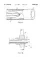
- FIG. 3is an enlarged detail cross-sectional schematic of the navigation catheter control of FIG. 1;
- FIG. 4is a view similar to FIG. 2 with the single movable treatment catheter replaced by a number of fixed treatment catheters;
- FIG. 5is a cross-sectional view taken along line 5--5 of FIG. 3;
- FIG. 6is a view similar to FIG. 2 but with the framework retracted.
- FIGS. 7A-Care enlarged detailed sectional views of the distal end of the treatment catheter showing three different ablative technologies.
- catheter navigation apparatus 10is constructed as a cardiac catheter navigation apparatus for performing percutaneous transmyocardial revascularization.
- Apparatus 10includes a catheter assembly 12 which is threaded through the aorta 14 and into the left ventricle 16 of a human heart 18.
- Catheter assembly 12includes two catheters: treatment catheter 20, the distal end 22 of which includes a lens for focusing laser energy delivered through fiber optic element 26 from laser 28.
- Distal end 22 of treatment catheter 20may be moved to and fro, that is, toward and away from, heart wall 29 in the direction indicated by arrow 30 by manipulating knob 32 of treatment catheter control 33 to translate it in the direction of arrows 34.
- Treatment catheter control 33is constructed and operates in a conventional manner as is well known in the art.
- Knob 32is translatable and rotatable with respect to its base 31.
- Knob 32is rotated in the direction of arrow 34 in order to curl the distal end 22 of treatment catheter 20 as shown by the dashed lines 22'.
- the distal end of navigation catheter 40includes a cagelike framework 42 which in FIG. 1 is in a deployed state in left ventricle 16.
- Framework 42includes a plurality of flexible strands 44, at least three, which are joined at their apex 46 at one end and joined at their base to a control wire, not visible in FIG. 1 but visible in FIG. 2.
- Framework 42is deployed by extending it beyond the distal end 48 of catheter assembly 12. This is done using navigation catheter control 50.
- Navigation catheter control 50includes a port 52 for receiving guide wire 54 which is used to install catheter assembly 12 in the patient's aorta and heart. This is done in the conventional fashion by threading guide wire 54 through the patient's arteries and into the ventricle, as the surgeon manipulates it in the normal way, and then sliding the catheter assembly 12 along the guide wire so that it follows the guide wire through the arteries and into the ventricle.
- Navigation catheter control 50also includes control knob 56 which can be translated in and out relative to base 57 along the longitudinal axis 55 of catheter 20 as indicated by arrow 58 to advance and retract framework 42. When framework 42 is advanced it deploys and expands to gently fill ventricle 16. When it is retracted it collapses and withdraws into the end 48 of catheter assembly 12 as can be seen in FIG. 6. When knob 56 is rotated as indicated by arrow 60, framework 42 is rotated, arrow 61, about its longitudinal axis 55 in ventricle 16.
- Orientational indicatorssuch as radiopaque, ultrasonically distinct or otherwise distinguishable indicia are provided on framework 42.
- two such indicia 60, 62, FIG. 2are provided on strand 44a and one such indicia 64 on strand 44b. So long as these two strands are not 180° opposed they can be used in simple flat fluoroscopy imaging to determine the orientation of framework 42 so that the surgeon with a quick glance at the fluoroscope image can determine the orientation of framework 42 and thus the position of the distal end 22 of treatment catheter 20.
- treatment catheter 20 and navigation catheter 40are combined together in lumen 70.
- knob 56is moved to and fro in the direction of arrow 58, FIG. 1, framework 42 is alternately deployed and retracted, respectively. If knob 56 is rotated as indicated by arrow 60, FIG. 1, framework 42 in turn rotates as indicated by arrow 61, FIG. 2.
- knob 32is rotated in the direction of arrow 34, FIG. 1, and this causes catheter 20 to uncurl as shown at 22" in FIG. 2, or to curl as shown 15 at position 22', FIG. 1.
- catheter assembly 12is fixed to base 51 of navigation catheter control 50 and knob 56 is fixed to navigation catheter 40 so that the motion of knob 56 is directly transmitted through catheter 40 to strands 44.
- the clearance between the inner surface of base 51 and the outer diameter of navigation catheter 40is small in order to provide a seal and prevent significant blood loss.
- Treatment catheter 20may include a hollow center portion which can contain a single strand of fiber optic material 26 as shown, or a multi-stranded optical bundle, or it may contain electrical conductors.
- Passage 80may also be used to contain guide wires for operating cutting or snipping mechanisms, as shown in FIG. 7C.
- Passage 80may also include a plurality of fiber optic elements 84 to be deployed as shown in FIG. 4 wherein there are a plurality of fiber optic elements 26a, 26b, 26c, 26d, contained in treatment catheter 20a, each of whose distal end 22a-d is fixably attached at block 72a-d to their respective strands so that no curling of the distal end is required and the rotational motion of knob 32, FIG.
- treatment catheter 20 and navigation catheter 40 included in the catheter assembly 12is shown in cross-section, FIG. 5, where the single fiber optic element 26 can be seen constituting treatment catheter 20 located inside of navigation catheter 40 which in turn is housed in the catheter assembly 12.
- Framework 42is shown in FIG. 6, in the collapsed position before and/or after it occupies the deployed position.
- the inventionhas been disclosed as an ablative device which uses laser energy conducted through a fiber optic element to produce the tissue ablation, this is not a necessary limitation of the invention.
- the distal end of treatment catheter 20' which is supported in mounting block 72'may include a pair of conductors 90, 92 for providing an electric field across the tissue.
- treatment catheter 20"may include an optical fiber 94 to provide a laser beam at its distal end 22".
- the distal end 22"" of treatment catheter 20""may include scissors 102 pivoted at 104 with a control wire 106 attached to one of the jaws 108 and threaded back through catheter 20"" to the proximal end where it can be manipulated to operate scissors 10.
- the inventionis also not limited to conventional fiber optic laser delivery as, for example, a side-firing optical fiber could be used.
Landscapes
- Health & Medical Sciences (AREA)
- Heart & Thoracic Surgery (AREA)
- Vascular Medicine (AREA)
- Cardiology (AREA)
- Engineering & Computer Science (AREA)
- Biomedical Technology (AREA)
- Nuclear Medicine, Radiotherapy & Molecular Imaging (AREA)
- Radiology & Medical Imaging (AREA)
- Life Sciences & Earth Sciences (AREA)
- Animal Behavior & Ethology (AREA)
- General Health & Medical Sciences (AREA)
- Public Health (AREA)
- Veterinary Medicine (AREA)
- Media Introduction/Drainage Providing Device (AREA)
- Laser Surgery Devices (AREA)
Abstract
Description
Claims (13)
Priority Applications (2)
| Application Number | Priority Date | Filing Date | Title |
|---|---|---|---|
| US08/734,135US5830210A (en) | 1996-10-21 | 1996-10-21 | Catheter navigation apparatus |
| PCT/US1997/019031WO1998017346A1 (en) | 1996-10-21 | 1997-10-20 | Catheter navigation apparatus |
Applications Claiming Priority (1)
| Application Number | Priority Date | Filing Date | Title |
|---|---|---|---|
| US08/734,135US5830210A (en) | 1996-10-21 | 1996-10-21 | Catheter navigation apparatus |
Publications (1)
| Publication Number | Publication Date |
|---|---|
| US5830210Atrue US5830210A (en) | 1998-11-03 |
Family
ID=24950454
Family Applications (1)
| Application Number | Title | Priority Date | Filing Date |
|---|---|---|---|
| US08/734,135Expired - Fee RelatedUS5830210A (en) | 1996-10-21 | 1996-10-21 | Catheter navigation apparatus |
Country Status (2)
| Country | Link |
|---|---|
| US (1) | US5830210A (en) |
| WO (1) | WO1998017346A1 (en) |
Cited By (42)
| Publication number | Priority date | Publication date | Assignee | Title |
|---|---|---|---|---|
| US5910150A (en)* | 1996-12-02 | 1999-06-08 | Angiotrax, Inc. | Apparatus for performing surgery |
| US5997536A (en)* | 1996-11-13 | 1999-12-07 | Sulzer Osypka Gmbh | Heart catheter with an electrode on a spreadable device |
| US6051008A (en)* | 1996-12-02 | 2000-04-18 | Angiotrax, Inc. | Apparatus having stabilization members for percutaneously performing surgery and methods of use |
| US6056744A (en) | 1994-06-24 | 2000-05-02 | Conway Stuart Medical, Inc. | Sphincter treatment apparatus |
| US6063082A (en)* | 1997-11-04 | 2000-05-16 | Scimed Life Systems, Inc. | Percutaneous myocardial revascularization basket delivery system and radiofrequency therapeutic device |
| US6073043A (en)* | 1997-12-22 | 2000-06-06 | Cormedica Corporation | Measuring position and orientation using magnetic fields |
| US6102926A (en)* | 1996-12-02 | 2000-08-15 | Angiotrax, Inc. | Apparatus for percutaneously performing myocardial revascularization having means for sensing tissue parameters and methods of use |
| US6165188A (en)* | 1996-12-02 | 2000-12-26 | Angiotrax, Inc. | Apparatus for percutaneously performing myocardial revascularization having controlled cutting depth and methods of use |
| US6258087B1 (en)* | 1998-02-19 | 2001-07-10 | Curon Medical, Inc. | Expandable electrode assemblies for forming lesions to treat dysfunction in sphincters and adjoining tissue regions |
| WO2001008575A3 (en)* | 1999-07-30 | 2001-08-16 | Cardiofocus Inc | Optical fiber basket device for cardiac photoablation |
| US20020068866A1 (en)* | 2000-08-14 | 2002-06-06 | Zikorus Arthur W. | Method and apparatus for positioning a catheter relative to an anatomical junction |
| US6427079B1 (en) | 1999-08-09 | 2002-07-30 | Cormedica Corporation | Position and orientation measuring with magnetic fields |
| US6613047B2 (en) | 1994-06-24 | 2003-09-02 | Curon Medical, Inc. | Apparatus to treat esophageal sphincters |
| US20040237321A1 (en)* | 2003-05-29 | 2004-12-02 | Rudko Robert I. | Replacement heart valve sizing device |
| US20040260322A1 (en)* | 2003-06-20 | 2004-12-23 | Rudko Robert I. | Endovascular tissue removal device |
| WO2005009314A1 (en)* | 2002-04-22 | 2005-02-03 | Frederick Walter George | Flushable absorbent article and method |
| US6866663B2 (en) | 1998-02-27 | 2005-03-15 | Curon Medical, Inc. | Method for treating a sphincter |
| US20050131510A1 (en)* | 2003-03-14 | 2005-06-16 | Chen James C. | Device for distal protection and treatment of blood vessels |
| US20050128742A1 (en)* | 2003-03-14 | 2005-06-16 | Chen James C. | Light generating device that self centers within a lumen to render photodynamic therapy |
| US20050228260A1 (en)* | 2003-03-14 | 2005-10-13 | Phillip Burwell | Light generating device to intravascular use |
| US20070129710A1 (en)* | 2003-07-28 | 2007-06-07 | Rudko Robert I | Endovascular tissue removal device |
| US20070244371A1 (en)* | 2006-04-04 | 2007-10-18 | Nguyen Hoa D | Phlebectomy illumination device and methods |
| US20080269846A1 (en)* | 2003-03-14 | 2008-10-30 | Light Sciences Oncology, Inc. | Device for treatment of blood vessels using light |
| US20090163810A1 (en)* | 2005-10-11 | 2009-06-25 | Carnegie Mellon University | Sensor Guided Catheter Navigation System |
| US7686799B2 (en) | 2000-07-13 | 2010-03-30 | Abbott Cardiovascular Systems Inc. | Deployment system for myocardial cellular material |
| US20100145415A1 (en)* | 2006-10-11 | 2010-06-10 | Dahm Jonathan S | Light delivery system |
| US20100280328A1 (en)* | 2009-05-01 | 2010-11-04 | Tyco Healthcare Group, Lp | Methods and systems for illumination during phlebectomy procedures |
| US20110077464A1 (en)* | 2003-03-14 | 2011-03-31 | Light Sciences Oncology, Inc. | Medical apparatus employing flexible light structures and methods for manufacturing same |
| US20110087091A1 (en)* | 2009-10-14 | 2011-04-14 | Olson Eric S | Method and apparatus for collection of cardiac geometry based on optical or magnetic tracking |
| EP2340868A1 (en) | 2004-07-19 | 2011-07-06 | Nexeon Medsystems, Inc. | Apparatus and methods for atraumatic implantation of bio-active agents |
| USRE42959E1 (en) | 1996-12-02 | 2011-11-22 | Abbott Cardiovascular Systems Inc. | Apparatus and methods for stimulating revascularization and/or tissue growth |
| US8308708B2 (en) | 2003-07-15 | 2012-11-13 | Abbott Cardiovascular Systems Inc. | Deployment system for myocardial cellular material |
| US9005197B2 (en) | 2010-10-26 | 2015-04-14 | Cook Medical Technologies Llc | Medical instrument for ablating tissue |
| US20150190616A1 (en)* | 2014-01-07 | 2015-07-09 | Aldo Antonio Salvestro | Medical device including manipulable portion with connected elongate members |
| JP2015533309A (en)* | 2012-10-22 | 2015-11-24 | ザ クリーブランド クリニック ファウンデーションThe Cleveland ClinicFoundation | Apparatus and method for targeting body tissue |
| US20160135750A1 (en)* | 2011-10-07 | 2016-05-19 | Boston Scientific Scimed, Inc. | Methods and systems for detection and thermal treatment of lower urinary tract conditions |
| EP2741695B1 (en)* | 2011-08-10 | 2018-01-10 | The Cleveland Clinic Foundation | Apparatus for targeting a body tissue |
| US10085694B2 (en) | 2011-07-15 | 2018-10-02 | Boston Scientific Scimed, Inc. | Systems and methods for monitoring organ activity |
| US10307610B2 (en) | 2006-01-18 | 2019-06-04 | Light Sciences Oncology Inc. | Method and apparatus for light-activated drug therapy |
| US10376711B2 (en) | 2003-03-14 | 2019-08-13 | Light Sciences Oncology Inc. | Light generating guide wire for intravascular use |
| US11305096B2 (en) | 2014-10-30 | 2022-04-19 | Kardium Inc. | Catheter system |
| US20220338758A1 (en)* | 2013-05-02 | 2022-10-27 | VS Medtech, Inc. | Systems and methods for measuring and characterizing interior surfaces of luminal structures |
Families Citing this family (2)
| Publication number | Priority date | Publication date | Assignee | Title |
|---|---|---|---|---|
| US6444657B1 (en) | 1998-12-31 | 2002-09-03 | Guilford Pharmaceuticals Inc. | Methods for treating certain diseases using naaladase inhibitors |
| DE102008005377B4 (en)* | 2008-01-22 | 2011-01-27 | Osypka, Peter, Dr.- Ing. | Bipolar electrode |
Citations (8)
| Publication number | Priority date | Publication date | Assignee | Title |
|---|---|---|---|---|
| US5026367A (en)* | 1988-03-18 | 1991-06-25 | Cardiovascular Laser Systems, Inc. | Laser angioplasty catheter and a method for use thereof |
| US5345936A (en)* | 1991-02-15 | 1994-09-13 | Cardiac Pathways Corporation | Apparatus with basket assembly for endocardial mapping |
| US5380316A (en)* | 1990-12-18 | 1995-01-10 | Advanced Cardiovascular Systems, Inc. | Method for intra-operative myocardial device revascularization |
| US5409000A (en)* | 1993-09-14 | 1995-04-25 | Cardiac Pathways Corporation | Endocardial mapping and ablation system utilizing separately controlled steerable ablation catheter with ultrasonic imaging capabilities and method |
| US5411025A (en)* | 1992-06-30 | 1995-05-02 | Cordis Webster, Inc. | Cardiovascular catheter with laterally stable basket-shaped electrode array |
| US5465717A (en)* | 1991-02-15 | 1995-11-14 | Cardiac Pathways Corporation | Apparatus and Method for ventricular mapping and ablation |
| US5558073A (en)* | 1993-10-12 | 1996-09-24 | Cardiac Pathways Corporation | Endocardial mapping apparatus with rotatable arm and method |
| US5593405A (en)* | 1994-07-16 | 1997-01-14 | Osypka; Peter | Fiber optic endoscope |
Family Cites Families (1)
| Publication number | Priority date | Publication date | Assignee | Title |
|---|---|---|---|---|
| US4660571A (en)* | 1985-07-18 | 1987-04-28 | Cordis Corporation | Percutaneous lead having radially adjustable electrode |
- 1996
- 1996-10-21USUS08/734,135patent/US5830210A/ennot_activeExpired - Fee Related
- 1997
- 1997-10-20WOPCT/US1997/019031patent/WO1998017346A1/enactiveApplication Filing
Patent Citations (8)
| Publication number | Priority date | Publication date | Assignee | Title |
|---|---|---|---|---|
| US5026367A (en)* | 1988-03-18 | 1991-06-25 | Cardiovascular Laser Systems, Inc. | Laser angioplasty catheter and a method for use thereof |
| US5380316A (en)* | 1990-12-18 | 1995-01-10 | Advanced Cardiovascular Systems, Inc. | Method for intra-operative myocardial device revascularization |
| US5345936A (en)* | 1991-02-15 | 1994-09-13 | Cardiac Pathways Corporation | Apparatus with basket assembly for endocardial mapping |
| US5465717A (en)* | 1991-02-15 | 1995-11-14 | Cardiac Pathways Corporation | Apparatus and Method for ventricular mapping and ablation |
| US5411025A (en)* | 1992-06-30 | 1995-05-02 | Cordis Webster, Inc. | Cardiovascular catheter with laterally stable basket-shaped electrode array |
| US5409000A (en)* | 1993-09-14 | 1995-04-25 | Cardiac Pathways Corporation | Endocardial mapping and ablation system utilizing separately controlled steerable ablation catheter with ultrasonic imaging capabilities and method |
| US5558073A (en)* | 1993-10-12 | 1996-09-24 | Cardiac Pathways Corporation | Endocardial mapping apparatus with rotatable arm and method |
| US5593405A (en)* | 1994-07-16 | 1997-01-14 | Osypka; Peter | Fiber optic endoscope |
Cited By (73)
| Publication number | Priority date | Publication date | Assignee | Title |
|---|---|---|---|---|
| US6056744A (en) | 1994-06-24 | 2000-05-02 | Conway Stuart Medical, Inc. | Sphincter treatment apparatus |
| US6613047B2 (en) | 1994-06-24 | 2003-09-02 | Curon Medical, Inc. | Apparatus to treat esophageal sphincters |
| US5997536A (en)* | 1996-11-13 | 1999-12-07 | Sulzer Osypka Gmbh | Heart catheter with an electrode on a spreadable device |
| USRE45638E1 (en) | 1996-12-02 | 2015-08-04 | Abbott Cardiovascular Systems Inc. | Apparatus for percutaneously performing myocardial revascularization having means for sensing tissue parameters and method of use |
| US5931848A (en)* | 1996-12-02 | 1999-08-03 | Angiotrax, Inc. | Methods for transluminally performing surgery |
| US5941893A (en)* | 1996-12-02 | 1999-08-24 | Angiotrax, Inc. | Apparatus for transluminally performing surgery |
| US6051008A (en)* | 1996-12-02 | 2000-04-18 | Angiotrax, Inc. | Apparatus having stabilization members for percutaneously performing surgery and methods of use |
| USRE42959E1 (en) | 1996-12-02 | 2011-11-22 | Abbott Cardiovascular Systems Inc. | Apparatus and methods for stimulating revascularization and/or tissue growth |
| US5910150A (en)* | 1996-12-02 | 1999-06-08 | Angiotrax, Inc. | Apparatus for performing surgery |
| US6102926A (en)* | 1996-12-02 | 2000-08-15 | Angiotrax, Inc. | Apparatus for percutaneously performing myocardial revascularization having means for sensing tissue parameters and methods of use |
| US6165188A (en)* | 1996-12-02 | 2000-12-26 | Angiotrax, Inc. | Apparatus for percutaneously performing myocardial revascularization having controlled cutting depth and methods of use |
| USRE43300E1 (en) | 1996-12-02 | 2012-04-03 | Abbott Cardiovascular Systems Inc. | Apparatus having stabilization members for percutaneously performing surgery and methods of use |
| US6660003B1 (en) | 1997-11-04 | 2003-12-09 | Scimed Life Systems, Inc. | Percutaneous myocardial revascularization basket delivery system and radiofrequency therapeutic device |
| US6063082A (en)* | 1997-11-04 | 2000-05-16 | Scimed Life Systems, Inc. | Percutaneous myocardial revascularization basket delivery system and radiofrequency therapeutic device |
| US6073043A (en)* | 1997-12-22 | 2000-06-06 | Cormedica Corporation | Measuring position and orientation using magnetic fields |
| US6258087B1 (en)* | 1998-02-19 | 2001-07-10 | Curon Medical, Inc. | Expandable electrode assemblies for forming lesions to treat dysfunction in sphincters and adjoining tissue regions |
| US8518032B2 (en) | 1998-02-27 | 2013-08-27 | Mederi Therapeutics Inc. | Method for treating a sphincter |
| US7449020B2 (en) | 1998-02-27 | 2008-11-11 | Curon Medical, Inc. | Method for treating a sphincter |
| US6866663B2 (en) | 1998-02-27 | 2005-03-15 | Curon Medical, Inc. | Method for treating a sphincter |
| WO2001008575A3 (en)* | 1999-07-30 | 2001-08-16 | Cardiofocus Inc | Optical fiber basket device for cardiac photoablation |
| US6427079B1 (en) | 1999-08-09 | 2002-07-30 | Cormedica Corporation | Position and orientation measuring with magnetic fields |
| US7686799B2 (en) | 2000-07-13 | 2010-03-30 | Abbott Cardiovascular Systems Inc. | Deployment system for myocardial cellular material |
| US20020068866A1 (en)* | 2000-08-14 | 2002-06-06 | Zikorus Arthur W. | Method and apparatus for positioning a catheter relative to an anatomical junction |
| US7789876B2 (en)* | 2000-08-14 | 2010-09-07 | Tyco Healthcare Group, Lp | Method and apparatus for positioning a catheter relative to an anatomical junction |
| WO2005009314A1 (en)* | 2002-04-22 | 2005-02-03 | Frederick Walter George | Flushable absorbent article and method |
| US10376711B2 (en) | 2003-03-14 | 2019-08-13 | Light Sciences Oncology Inc. | Light generating guide wire for intravascular use |
| US7252677B2 (en) | 2003-03-14 | 2007-08-07 | Light Sciences Oncology, Inc. | Light generating device to intravascular use |
| US8685071B2 (en) | 2003-03-14 | 2014-04-01 | Purdue Pharmaceutical Products L.P. | Medical apparatus employing flexible light structures |
| US20080027517A1 (en)* | 2003-03-14 | 2008-01-31 | Light Sciences Oncology, Inc. | Light generating device for intravascular use |
| WO2004082736A3 (en)* | 2003-03-14 | 2005-10-27 | Light Sciences Corp | Light generating device to intravascular use |
| US20080269846A1 (en)* | 2003-03-14 | 2008-10-30 | Light Sciences Oncology, Inc. | Device for treatment of blood vessels using light |
| US20050228260A1 (en)* | 2003-03-14 | 2005-10-13 | Phillip Burwell | Light generating device to intravascular use |
| US20050128742A1 (en)* | 2003-03-14 | 2005-06-16 | Chen James C. | Light generating device that self centers within a lumen to render photodynamic therapy |
| US20050131510A1 (en)* | 2003-03-14 | 2005-06-16 | Chen James C. | Device for distal protection and treatment of blood vessels |
| US7730894B2 (en) | 2003-03-14 | 2010-06-08 | Light Sciences Oncology, Inc. | Photodynamic therapy apparatus and method for vascular tissue treatment |
| US20110077464A1 (en)* | 2003-03-14 | 2011-03-31 | Light Sciences Oncology, Inc. | Medical apparatus employing flexible light structures and methods for manufacturing same |
| US7007396B2 (en)* | 2003-05-29 | 2006-03-07 | Plc Medical Systems, Inc. | Replacement heart valve sizing device |
| US20040237321A1 (en)* | 2003-05-29 | 2004-12-02 | Rudko Robert I. | Replacement heart valve sizing device |
| US20040260322A1 (en)* | 2003-06-20 | 2004-12-23 | Rudko Robert I. | Endovascular tissue removal device |
| US7537592B2 (en)* | 2003-06-20 | 2009-05-26 | Plc Medical Systems, Inc. | Endovascular tissue removal device |
| US20040260276A1 (en)* | 2003-06-20 | 2004-12-23 | Rudko Robert I. | Endovascular tissue removal device |
| US7377916B2 (en)* | 2003-06-20 | 2008-05-27 | Plc Medical Systems, Inc. | Endovascular tissue removal device |
| US8308708B2 (en) | 2003-07-15 | 2012-11-13 | Abbott Cardiovascular Systems Inc. | Deployment system for myocardial cellular material |
| US20070129710A1 (en)* | 2003-07-28 | 2007-06-07 | Rudko Robert I | Endovascular tissue removal device |
| EP2340868A1 (en) | 2004-07-19 | 2011-07-06 | Nexeon Medsystems, Inc. | Apparatus and methods for atraumatic implantation of bio-active agents |
| US20090163810A1 (en)* | 2005-10-11 | 2009-06-25 | Carnegie Mellon University | Sensor Guided Catheter Navigation System |
| US7981038B2 (en) | 2005-10-11 | 2011-07-19 | Carnegie Mellon University | Sensor guided catheter navigation system |
| US8480588B2 (en) | 2005-10-11 | 2013-07-09 | Carnegie Mellon University | Sensor guided catheter navigation system |
| US11369339B2 (en) | 2005-10-11 | 2022-06-28 | University of Pittsburgh—of the Commonwealth System of Higher Education | Sensor guided catheter navigation system |
| US9566043B2 (en) | 2005-10-11 | 2017-02-14 | Carnegie Mellon University | Sensor guided catheter navigation system |
| US9861338B2 (en) | 2005-10-11 | 2018-01-09 | Carnegie Mellon University | Sensor guided catheter navigation system |
| US9017260B2 (en) | 2005-10-11 | 2015-04-28 | Carnegie Mellon University | Sensor guided catheter navigation system |
| US10307610B2 (en) | 2006-01-18 | 2019-06-04 | Light Sciences Oncology Inc. | Method and apparatus for light-activated drug therapy |
| US20070244371A1 (en)* | 2006-04-04 | 2007-10-18 | Nguyen Hoa D | Phlebectomy illumination device and methods |
| US8685005B2 (en) | 2006-10-11 | 2014-04-01 | Purdue Pharmaceutical Products L.P. | Light delivery system |
| US20100145415A1 (en)* | 2006-10-11 | 2010-06-10 | Dahm Jonathan S | Light delivery system |
| USRE46504E1 (en) | 2006-10-11 | 2017-08-08 | Purdue Pharmaceutical Products L.P. | Light delivery system |
| US20100280328A1 (en)* | 2009-05-01 | 2010-11-04 | Tyco Healthcare Group, Lp | Methods and systems for illumination during phlebectomy procedures |
| US8409098B2 (en) | 2009-10-14 | 2013-04-02 | St. Jude Medical, Atrial Fibrillation Division, Inc. | Method and apparatus for collection of cardiac geometry based on optical or magnetic tracking |
| US20110087091A1 (en)* | 2009-10-14 | 2011-04-14 | Olson Eric S | Method and apparatus for collection of cardiac geometry based on optical or magnetic tracking |
| US9005197B2 (en) | 2010-10-26 | 2015-04-14 | Cook Medical Technologies Llc | Medical instrument for ablating tissue |
| US10085694B2 (en) | 2011-07-15 | 2018-10-02 | Boston Scientific Scimed, Inc. | Systems and methods for monitoring organ activity |
| EP2741695B1 (en)* | 2011-08-10 | 2018-01-10 | The Cleveland Clinic Foundation | Apparatus for targeting a body tissue |
| US20160135750A1 (en)* | 2011-10-07 | 2016-05-19 | Boston Scientific Scimed, Inc. | Methods and systems for detection and thermal treatment of lower urinary tract conditions |
| JP2015533309A (en)* | 2012-10-22 | 2015-11-24 | ザ クリーブランド クリニック ファウンデーションThe Cleveland ClinicFoundation | Apparatus and method for targeting body tissue |
| US11701033B2 (en)* | 2013-05-02 | 2023-07-18 | VS Medtech, Inc. | Systems and methods for measuring and characterizing interior surfaces of luminal structures |
| US20220338758A1 (en)* | 2013-05-02 | 2022-10-27 | VS Medtech, Inc. | Systems and methods for measuring and characterizing interior surfaces of luminal structures |
| US20150190616A1 (en)* | 2014-01-07 | 2015-07-09 | Aldo Antonio Salvestro | Medical device including manipulable portion with connected elongate members |
| US11033191B2 (en) | 2014-01-07 | 2021-06-15 | Kardium Inc. | Medical device including manipulable portion with connected elongate members |
| US10716477B2 (en) | 2014-01-07 | 2020-07-21 | Kardium Inc. | Medical device including manipulable portion with connected elongate members |
| US10278590B2 (en) | 2014-01-07 | 2019-05-07 | Kardium Inc. | Medical device including manipulable portion with connected elongate members |
| US9993160B2 (en)* | 2014-01-07 | 2018-06-12 | Kardium Inc. | Medical device including manipulable portion with connected elongate members |
| US11305096B2 (en) | 2014-10-30 | 2022-04-19 | Kardium Inc. | Catheter system |
Also Published As
| Publication number | Publication date |
|---|---|
| WO1998017346A1 (en) | 1998-04-30 |
Similar Documents
| Publication | Publication Date | Title |
|---|---|---|
| US5830210A (en) | Catheter navigation apparatus | |
| JP4448614B2 (en) | Tissue penetrating catheter system with built-in image transducer | |
| US5755714A (en) | Shaped catheter for transmyocardial revascularization | |
| US7637870B2 (en) | Tissue penetrating catheters having integral imaging transducers and their methods of use | |
| US5769843A (en) | Percutaneous endomyocardial revascularization | |
| US6540695B1 (en) | Biopsy anchor device with cutter | |
| US6830568B1 (en) | Guiding catheter system for ablating heart tissue | |
| US5651785A (en) | Optical fiber catheter and method | |
| JP4125482B2 (en) | Percutaneous myocardial revascularization device | |
| US5766163A (en) | Controllable trocar for transmyocardial revascularization (TMR) via endocardium method and apparatus | |
| US6120516A (en) | Method for treating vascular occlusion | |
| US6010449A (en) | Intravascular catheter system for treating a vascular occlusion | |
| WO1998017346B1 (en) | Catheter navigation apparatus | |
| US20200214546A1 (en) | Methods and devices for visualization and access | |
| US5782824A (en) | Cardiac catheter anchoring | |
| EP0904797A2 (en) | Steerable catheter with tip alignment and surface contact detector | |
| JP2020530373A (en) | Directional balloon transseptal insertion device for medical procedures | |
| CZ189494A3 (en) | Process and apparatus for intersticial execution of therapeutic actions or diagnosis in a body organ | |
| WO1987004080A2 (en) | Surgical catheters | |
| US5651786A (en) | Mapping catheter and method | |
| US20250195847A1 (en) | Medical catheter | |
| CN1204244A (en) | Device. system and method for interstitial transvascular | |
| EP1768591B1 (en) | Flexible endoscope for endo luminal access radio frequency tumor ablation | |
| US20240122589A1 (en) | Surgical space maker device | |
| CA2248328A1 (en) | Steerable catheter with tip alignment and surface contact detector |
Legal Events
| Date | Code | Title | Description |
|---|---|---|---|
| AS | Assignment | Owner name:LASER ENGINEERING, INC., MASSACHUSETTS Free format text:ASSIGNMENT OF ASSIGNORS INTEREST;ASSIGNORS:RUDKO, ROBERT I.;NEGUS, CHARLES CHRISTOPHER;LINHARES, STEPHEN J.;AND OTHERS;REEL/FRAME:008277/0300 Effective date:19961018 | |
| AS | Assignment | Owner name:PLC MEDICAL SYSTEMS, INC., MASSACHUSETTS Free format text:FROM LASER ENGINEERING TO PLC MEDICAL SYSTEMS;ASSIGNORS:RUDKO, ROBERT I.;NEGUS, CHARLES CHRISTOPHER;LINHARES, STEPHEN J.;AND OTHERS;REEL/FRAME:008500/0319 Effective date:19961018 | |
| FPAY | Fee payment | Year of fee payment:4 | |
| REMI | Maintenance fee reminder mailed | ||
| FPAY | Fee payment | Year of fee payment:8 | |
| REMI | Maintenance fee reminder mailed | ||
| LAPS | Lapse for failure to pay maintenance fees | ||
| STCH | Information on status: patent discontinuation | Free format text:PATENT EXPIRED DUE TO NONPAYMENT OF MAINTENANCE FEES UNDER 37 CFR 1.362 | |
| FP | Expired due to failure to pay maintenance fee | Effective date:20101103 | |
| AS | Assignment | Owner name:NOVADAQ TECHNOLOGIES INC., CANADA Free format text:RELEASE BY SECURED PARTY;ASSIGNOR:MIDCAP FUNDING IV TRUST (AS SUCCESSOR AGENT TO MIDCAP FINANCIAL TRUST);REEL/FRAME:043786/0344 Effective date:20170901 Owner name:NOVADAQ CORP., CANADA Free format text:RELEASE BY SECURED PARTY;ASSIGNOR:MIDCAP FUNDING IV TRUST (AS SUCCESSOR AGENT TO MIDCAP FINANCIAL TRUST);REEL/FRAME:043786/0344 Effective date:20170901 Owner name:NOVADAQ TECHNOLOGIES INC., CANADA Free format text:RELEASE BY SECURED PARTY;ASSIGNOR:MIDCAP FINANCIAL TRUST;REEL/FRAME:043788/0799 Effective date:20170901 Owner name:NOVADAQ CORP., CANADA Free format text:RELEASE BY SECURED PARTY;ASSIGNOR:MIDCAP FINANCIAL TRUST;REEL/FRAME:043788/0799 Effective date:20170901 |