US5830064A - Apparatus and method for distinguishing events which collectively exceed chance expectations and thereby controlling an output - Google Patents
Apparatus and method for distinguishing events which collectively exceed chance expectations and thereby controlling an outputDownload PDFInfo
- Publication number
- US5830064A US5830064AUS08/683,878US68387896AUS5830064AUS 5830064 AUS5830064 AUS 5830064AUS 68387896 AUS68387896 AUS 68387896AUS 5830064 AUS5830064 AUS 5830064A
- Authority
- US
- United States
- Prior art keywords
- series
- digital data
- data values
- random
- event generator
- Prior art date
- Legal status (The legal status is an assumption and is not a legal conclusion. Google has not performed a legal analysis and makes no representation as to the accuracy of the status listed.)
- Expired - Lifetime
Links
Images


Classifications
- G—PHYSICS
- G06—COMPUTING OR CALCULATING; COUNTING
- G06F—ELECTRIC DIGITAL DATA PROCESSING
- G06F7/00—Methods or arrangements for processing data by operating upon the order or content of the data handled
- G06F7/58—Random or pseudo-random number generators
- A63F13/10—
- A—HUMAN NECESSITIES
- A63—SPORTS; GAMES; AMUSEMENTS
- A63F—CARD, BOARD, OR ROULETTE GAMES; INDOOR GAMES USING SMALL MOVING PLAYING BODIES; VIDEO GAMES; GAMES NOT OTHERWISE PROVIDED FOR
- A63F13/00—Video games, i.e. games using an electronically generated display having two or more dimensions
- A63F13/45—Controlling the progress of the video game
- A—HUMAN NECESSITIES
- A63—SPORTS; GAMES; AMUSEMENTS
- A63F—CARD, BOARD, OR ROULETTE GAMES; INDOOR GAMES USING SMALL MOVING PLAYING BODIES; VIDEO GAMES; GAMES NOT OTHERWISE PROVIDED FOR
- A63F13/00—Video games, i.e. games using an electronically generated display having two or more dimensions
- A63F13/60—Generating or modifying game content before or while executing the game program, e.g. authoring tools specially adapted for game development or game-integrated level editor
- G—PHYSICS
- G07—CHECKING-DEVICES
- G07F—COIN-FREED OR LIKE APPARATUS
- G07F17/00—Coin-freed apparatus for hiring articles; Coin-freed facilities or services
- G07F17/32—Coin-freed apparatus for hiring articles; Coin-freed facilities or services for games, toys, sports, or amusements
Definitions
- This inventionrelates to the field of electronic detectors and controllers, and more specifically to a method and apparatus of generating values and detecting whether the values fall outside chance probabilities.
- Random-event generatorsor random-number generators.
- Such generatorsinclude true-random-number generators (that generate truly random numbers) and pseudo-random-number generators (those devices and computer programs that generate pseudo-random numbers, which are seemingly random numbers, but which in actuality are more or less deterministic).
- Pseudo-random number generatorscan include devices or programs that generate a complex sequence of numbers that are based on a "seed," and that, given one particular seed, will generate the same sequence of pseudo-random numbers.
- bias-true-random-number generatorsthat generate a biased sequence of random numbers, wherein the bias is due to perhaps some environmental factor, such as electrical or magnetic fields, temperature, voltage, circuit drift, or some other factor or field.
- Game devicessuch as self-powered toy vehicles or computer video games, often have user-input control devices, such as joystick controllers, keyboards, trackballs, or "mice” which translate manual movements of a human operator (e.g., hand or finger movements) into control signals for moving or controlling operation of the toy or game.
- user-input control devicessuch as joystick controllers, keyboards, trackballs, or "mice” which translate manual movements of a human operator (e.g., hand or finger movements) into control signals for moving or controlling operation of the toy or game.
- Each of these user-input control devicesrequires some muscular movement by the user.
- a device that responded to human intention from a human without any direct connection, and could "read” the thoughts or intentions of the human in order to control some devicehas been dreamt of, but never realized.
- the present inventionprovides a field random-event generator (F-REG) that generates sequences of "random" numbers or events, and that is small, portable, “calibrateable,” and usable in the field.
- F-REGfield random-event generator
- the F-REGis designed to be miniaturized and inexpensive.
- the present inventionalso provides a method and apparatus for detecting engineering anomalies, or improbable sequences in the numbers generated by the random-event generator, that is usable in the field.
- the present inventionalso provides a method and apparatus for detecting signal or number excursions which exceed certain probabilities, and for activating switches and/or control signals based upon detection of such events.
- Another aspect of the present inventionis a "chance expectation detector”: a method and apparatus for detecting signal or number excursions which exceed certain probabilities.
- means for activating switches and/or control signals based upon detection of such eventsare provided in the chance expectation detector.
- One embodimentuses a small and inexpensive random source based upon the electronic noise produced in a resistor, diode, or some such similar effect, to generate a series of binary values (bits).
- a further embodimentselectively inverts some of the bits to reduce first-order bias effects.
- One such embodimentselectively inverts bits according to a pseudo-random series of values.
- a result series, having a predetermined number of these binary values,is accumulated to generate a sample result.
- the mean expected value and standard deviation for this numberare calculated or predetermined empirically by calibration, and, in one embodiment, the number is compared to these expectations. In one embodiment, for example, 1024 bits are counted to generate an output number having an expected mean of 512 and standard deviation of 16. A further embodiment then subtracts 512 from such a count to generate an output number having an expected mean of zero and standard deviation of 16.
- One implementationuses an internal microprocessor to encode an asynchronous computer-interface signal to transmit the output number and/or statistical information regarding the output number; another utilizes a Universal Asynchronous Receiver Transmitter (UART) chip to perform this function.
- UARTUniversal Asynchronous Receiver Transmitter
- Another embodiment of the present inventionprovides a system including a physical random-value source, electronic circuitry to amplify and shape the signal, a stored-program computer to provide statistical analysis, software or firmware to apply the detected and analyzed signal to the performance of some task and one or more output devices that provide feedback to an operator, player or control system. Analysis is accomplished by comparing statistically computed values derived from the random-value source to preset statistical threshold values corresponding to the probabilities of those computed values occurring by chance. Statistical parameters compared include, but are not limited to, the mean of the distribution, the time derivative of the distribution, and/or the time integral of the distribution.
- the systemmay include a game (such as a video game), a mechanical toy, or means for controlling other devices, such as means for adjusting of set points for heating and air conditioning or the intensity level of room lighting, where precision of operation and response time are not critical.
- the present inventionprovides an interface connectable to a serial port of a microcomputer, and is provided with software for experiments and calibrations, compiled for IBM PC/AT or similar clone equipment.
- One application of the present inventionis the investigation of anomalous interaction between an operator and random physical systems, whether by serious scientists or curious members of the public who would like to conduct experiments on their own.
- an F-REGgenerates a signal that is then coupled to a toy or game and is used to control the movement, operation, and/or function of the toy or game.
- a useris encouraged to try to use his or her subjective intention to affect the control provided to the toy or game by the F-REG.
- FIG. 1is a diagram showing field-random-event generator (F-REG) 100 and computer 99.
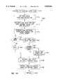
- FIG. 2is a block diagram of one embodiment of a chance-expectation-detector (CED) system 200 including a CED 700.
- CEDchance-expectation-detector
- FIG. 3is a table of a seventy-byte pseudo-random sequence 299 having low autocorrelation useful for selectively inverting bits in a F-REG 100 or CED 700.
- FIG. 4is a block diagram of the electronics of one embodiment of a field-random-event generator 100.
- FIG. 5Ais a block diagram of one embodiment of image-blender program 500 that takes input from F-REG 100 and generates an image display output 512 and analysis output 572.
- FIG. 5Bis a block diagram of one embodiment of image-blender program 500' that takes input from CED 700 and generates an image display output 512 and analysis output 572.
- FIG. 6Ais a block diagram of a toy 600 controlled by toy controller 660.
- FIG. 6Bis a block diagram of a toy 699 controlled by toy controller 660.
- FIG. 6Cis a block diagram of a toy controller 660.
- FIG. 7Ais a block diagram of one embodiment of chance-expectation-detector apparatus 700 for distinguishing noise or random events which collectively exceed chance expectations and thereby controlling an output.
- FIG. 7Bis a block diagram of another embodiment of chance-expectation-detector apparatus 700, this embodiment using a microprocessor 150 to perform one or more of the functions described in FIG. 7A.
- FIG. 7Cis a flow diagram of one embodiment of chance-expectation-detector apparatus 700.
- FIG. 8A and FIG. 8Bis a schematic of one embodiment of chance-expectation-detector apparatus 700.
- FIG. 9is a block diagram and flow diagram of one embodiment of toy-control software 900 that uses output 130 of field-random-event generator 100 and generates motor-driver control signal 952.
- FIG. 10is a flow diagram of one embodiment of software 1000 that runs in microcomputer 150.
- FIG. 11is a flow diagram of one embodiment of input-sampling process 1100 that runs in microcomputer 150.
- FIG. 12is a flow diagram of one embodiment of asynchronous-serial-output process 1200 that runs in microcomputer 150.
- FIG. 13is a flow diagram of one embodiment of offset-bias-calibration routine 1300 that runs in microcomputer 150.
- FIG. 14is a flow diagram of one embodiment of analysis-and-control process 1400 that runs in microcomputer 150.
- FIG. 15Ais a graph showing an accumulated output of F-REG 100 having a relatively small standard deviation.
- FIG. 15Bis a graph showing an accumulated output of F-REG 100 having a relatively large standard deviation.
- FIG. 15Cis a graph showing an accumulated output-of F-REG 100 having a relatively large standard deviation, also showing a parabola where the significance level is e.g., 0.05, with 2 excursions beyond this level.
- FIG. 16is a block diagram of a toy cat controlled by chance-expectation-detector 700.
- FIG. 17is a block diagram and flow diagram of one embodiment of software 300 that uses output 130 of field-random-event generator 100.
- FIG. 18is a data-structure diagram of one embodiment of an index file 410 used to hold data for software 300.
- FIG. 1is a diagram showing field-random-event generator (F-REG) 100 and computer 99.
- field-random-event generator 100is a portable stand-alone unit contained in a 5 ⁇ 7 ⁇ 2 inch aluminum box. In this embodiment, a printed circuit board and precision components are used to achieve a highly standardized device with reliable performance.
- a separate 12-volt DC supply 101is connected to F-REG 100.
- F-REG 100is powered by an internal battery.
- F-REG 100is powered from computer 99.
- F-REG 100is connected to computer 99 by wire through DB9 connector 153.
- an infra-red or other wireless transmitter and receiveris used to couple signals from F-REG 100 to computer 99.
- FIG. 2is a block diagram of one embodiment of a chance-expectation-detector (“CED") system 200 including a chance-expectation-detector 700 and various optional result controllers.
- a source of a series values having a stochastic or random componentwhich in the embodiment shown is a portable field random event generator (“F-REG") 100, is provided.
- the series of valuesis a serial sequence of random binary values ("bits").
- the series of bitsare gathered into bytes or data words by driver 124 (i.e., converted from a series of 1-bit words to a series of, e.g., 8-bit bytes) for parallel transmission to other components of CED system 200.
- F-REG 100includes a noise source 110 that provides a conditioned, amplified analog noise signal 115 that is representative of some physical process having a stochastic or random component, such as noise from a resistor.
- Noise source 110may also contain a bias caused by one or more external fields, temperatures, or other sources of bias such as human volitional or emotional state.
- analog noise signal 115is coupled to sampler 116 that generates a series of digital data values 117 representative analog noise signal 115 at a sequence of time points, e.g., once every millisecond or once every microsecond as determined by clock 113.
- sampler 116is a one-bit analog-to-digital convertor (“ADC”) that generates a series of random bits as determined by analog signal 115.
- sampler 116is an N-bit analog-to-digital convertor (“ADC”) that generates a series of random N-bit values as determined by analog signal 115.
- the series of digital data values 117is then coupled through selective invertor 118 that selectively inverts some of the series of digital data values 117 (as selected by selection pattern 217) to generate a selectively inverted series of digital data values 119.
- selective invertor 118includes a one-bit exclusive-OR circuit fed by a signal on selection pattern 217 having one-half the frequency of clock 113, thus inverting every other bit of the series of digital data values 117.
- selective invertor 118includes an exclusive-OR circuit fed by a series of pseudo-random bits, thus inverting bits of the series of digital data values 117 in a pseudo-random manner.
- the series of pseudo-random bitsis derived by selecting seventy different one-byte data values (each having 8-bits) that each have four ones and four zeros (in binary notation); these seventy bytes are then placed into 70-byte strings and each string is tested for overall autocorrelation (the proportion of bits that have the corresponding bits the same in successive bytes as determined by a sum-of-squares of lag-1 autocorrelation coefficients between corresponding bits in adjacent bytes). In one such embodiment, approximately 100,000 different reordered 70-byte sequences are tested, and the one sequence having the lowest autocorrelation value is selected. This selected 70-byte pseudo-random sequence mask 299 (as shown in FIG.
- driver 124is a UART or RS232 driver coupled to a wire.
- driver 124is an infra-red transmitter that transmits an infra-red beam encoding the selectively inverted series of digital data values 119 in much the way that commands are transmitted by a television remote-control device.
- Other embodimentsuse other coupling means.
- Signal 130is coupled to variance accumulator 210 and/or decision maker and controller 250.
- Variance accumulator 210performs one or more statistical analyses on the selectively inverted series of digital data values 119 transmitted in signal 130.
- a fixed number of the selectively inverted series of digital data values 119are added together (i.e., the number of "ONE" bits in each byte is added to an accumulator) to generate a SAMPLE -- RESULT 211.
- 1024 bits of the selectively inverted series of digital data values 119are processed, counting the number of "ONE" bits.
- the number of "ONE" bits in one byteis added to the accumulator, and the value "four” is subtracted (four being the expected mean of the number of one bits in eight random bits) for each of 128 bytes, in order to generate a SAMPLE -- RESULT 211 having a mean of zero and a value equal to the deviation the number of "ONE"s of that sample from the expected mean of 512.
- one or more values of SAMPLE -- RESULT 211are stored in storage 220 for later use.
- decision maker and controller 250is a circuit configured to make a logical decision based on one or more of: the selectively inverted series of digital data values 119 on signal 130, SAMPLE -- RESULT 211, or values stored in storage 220, and to generate one or more control signals 251 to control a result.
- the result controlledincludes controlling heating-ventilating-air-conditioning (HVAC) controller 243 that in turn controls HVAC equipment 244 to, e.g., control air temperature in a building, or a fan's speed.
- HVACheating-ventilating-air-conditioning
- Other such embodimentsallow control of a temperature of a gaseous, liquid (such as the water in a waterbed) or solid material (such as a heating pad).
- the result controlledincludes controlling light controller 233 that in turn controls lights 234 in order to control a light intensity or color (such as mood lighting dimming).
- the result controlledincludes controlling motor controller 533 that in turn controls motor 534 in order to control, for example, movement in a toy.
- the result controlledincludes controlling audio/video controller 525 that in turn controls speakers 524 in order to control the sound produced (i.e., program, station, device or channel selection), or its intensity.
- audio/video controller 525includes a remote-control receiver of a television, stereo, or other home-entertainment device, and the result controlled is, e.g., the channel selection for the television or the sound loudness, etc.
- decision maker and controller 250includes an infra-red transmitter and encoder compatible with the remote-control receiver of audio/video controller 525.
- the result controlledincludes controlling video-game program 550 that in turn controls video display 514 and/or speakers 524 in order to control the picture and/or sound produced (i.e., the control of game flow or operation or selection), or the sound loudness or timbre, or light intensity of the computer-generated image.
- controlling video-game program 550controls video display 514 and/or speakers 524 in order to control the picture and/or sound produced (i.e., the control of game flow or operation or selection), or the sound loudness or timbre, or light intensity of the computer-generated image.
- the result controlledincludes controlling a video display or printed output of a computer in order to display a computer-controlled indication of an emotional or volitional state of one or more persons. Otherwise anomalous results of experiments statistically indicate a strong correlation between the emotional or volitional state of one or more persons and the results displayed.
- One use for such an indicationis to provide a non-invasive sample of public opinion.
- Another use for such an indicationis to provide a computer-controlled indication of a mental or physiological state of one or more persons, particularly if that person is unwilling or unable to otherwise communicate (such as a mentally disturbed person).
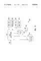
- FIG. 4is a block diagram of one embodiment of the electronics of field-random-event generator 100.
- the analog circuit section 110 of the boardcontains a noise source 102 (such as a resistor or diode producing "Johnson” noise) and a multi-stage amplification and clipping circuit 108 that includes one or more amplifier stages 104 through 106.
- the resulting analog signal 109has a white noise spectrum that is flat within approximately one dB over the frequency range from 500 to 30,000 Hz.
- Analog signal 109is compared with a DC reference level, V REF 111, yielding a digital output 115 that is 3.6 volts (a logical ONE) when the analog input exceeds the reference voltage and 0.4 volts (a logical ZERO) when it does not.
- This digital output signal 115passed to the digital circuit section 120 where it is periodically sampled by an edge-triggered flip-flop 114 that locks in (or holds) a sampled bit of 1 or 0 from an edge of clock 113 of until the next such edge, thus for one clocking period.
- sampling rate of clock 113is 1000 samples per second.
- this continuous sequence of bits 117is then passed through a "template" stage 118 to produce an "alternated" sequence, in order to preclude first-order bias of the mean due to short- or long-term drift in any analog component values.
- template stage 118exclusive-ORs the sequence of bits 117 with an alternating template series of ones and zeros (i.e., 0, 1, 0, 1, 0, 1, . . .
- template stage 118exclusive-ORs the sequence of bits 117 with a pseudo-random template series of ones and zeros (e.g., a predetermined stored sequence of numbers having known statistical parameters such as 50% zeros and 50% ones such as pseudo-random sequence mask 299 shown in FIG. 3) so that bits of bit sequence 117 are toggled according to the template series.
- the pseudo-random template seriesis stored as digital values in a table in computer memory.
- This "alternated" sequence of bits 119is then acquired by an 8-bit shift register 122, whose content is transferred at 18 millisecond intervals to a UART chip 124 for asynchronous transmission as a data byte in a sequence of data bytes.
- Serial-out signal 130provides these bytes which are transmitted to the serial port of the computer at 9600 baud in one embodiment, where they are read and converted to REG data by dedicated software running in computer 99.
- the digital circuit section 120 and analog circuit section 110 of field-random-event generator 100are isolated from each other spatially, and the geometry is fixed by using printed circuitry. No digital operations are performed during each time period of the analog sampling, in order to avoid any electrical cross-over.
- a separate, external power supply 101is used to minimize electromagnetic fields within the box of field-random-event generator 100.
- field-random-event generator 100is protected against most external sources of electromagnetic interference, it should not be installed immediately adjacent to the video display terminal of computer 99 where strong magnetic fields may be expected.
- field-random-event generator 100is provided with a four foot cable and a nine pin serial connector; adapters are available to connect such a 9-pin connector to a 25 pin serial port.
- settings of one or more internal dip-switches 142allow different sampling and byte generation rates and other adjustments, but these options are used only in testing and setup for initial calibration, and switch settings should not be changed without subsequent calibrations.
- a potentiometer 144is used to adjust the reference voltage, and its setting also should not be changed. Note that alteration of any settings of dip-switch 142 or potentiometer 144 will nullify calibrations previously performed and may affect nominal performance.
- field-random-event generator 100is designed for use with specific software 300 (see FIG. 17 description below), which assumes nominal calibrated settings.
- FIG. 5Ais a block diagram of one embodiment of image-blender program 500 that takes input from F-REG 100 and generates an image display output 512 and analysis output 572.
- the overall purpose of image-blender program 500is to "blend" two images, Image A and Image B, into a single Composite Image that is then displayed onto display 514 of computer 99.
- the blended imageis changed over time to include more of one or the other image, based on the values generated by F-REG 100. If a series of values from F-REG 100 overwhelmingly goes in one direction or the other, the resultant picture displayed will "saturate" with the corresponding image (either Image A or Image B, depending on whether the values indicated more zeroes or ones).
- a "game of chance”is thus produced, in which the user is given the impression (or perhaps the reality) that they control the game by conscious intention.
- a useris encouraged to attempt to control the numbers generated by F-REG 100, thus producing either the effect or the appearance of conscious control of the image displayed.
- two users"compete,” each trying to use conscious intention to force the values from F-REG 100 to go in their respective favor; and if one image saturates, the game stops with that image displayed, and the corresponding "player” is declared the winner.
- a series of such gamesis scored to comprise a match, with each player trying to win as many games within the match as possible and achieve the best score.
- FIG. 5Bis a block diagram of one embodiment of image-blender program 500' that takes input from CED 700 and generates an image display output 512 and analysis output 572.
- Image A 502 and Image B 504are selected from image file 503 (that has a plurality of various images such as photographs of mountains, beaches, buildings, planets, etc.) under control of image selection logic 505 and user input 501.
- User input 501also drives game mode 506 which specifies whether the game is to be "supportive” wherein players try to achieve a common goal (all trying to get the same image to saturate), or “competitive” wherein each player tries to achieve separate goals (each trying to get his or her own picture to saturate).
- User input 501also drives game choice 507 which controls whether the game in played in standard mode (manual user input starts each game, and the game runs until one image saturates and completely replaces the other image(s); continuous mode (a new game automatically starts after the previous game ends); or best of series (a new game automatically starts after the previous game ends until one player has won a predetermined number of games, e.g., four out of seven). In one embodiment, more than two images are mixed, representing the corresponding number of players.
- User input 501also drives game time 508 which determines the time each game will run, and/or the speed of change (i.e., the sensitivity to deviations) in each game.
- image pixel mixer 510selects pixels to be displayed from the corresponding pixel of Image A or Image B depending on deviation values provided by CED 700.
- image pixel mixer 510drives pixel saturation and image fixation block 515.
- the magnitude of deviation in one direction or the otherdetermines the number of pixels that will be switched, and the determination of which pixels to change is based on a random or pseudo-random criteria, in order that portions of the entire resultant image are evenly changed. After "enough" values from CED 700 have been received to achieve an overall net deviation meeting a certain predetermined threshold, the resultant image will "saturate" to be either Image A or Image B, with no pixels of the non-selected image being displayed.
- Pixel saturation and image fixation block 515also drives scorecard 516 (which keeps track of how many times each player has won), data analysis 517 (which tracks the statistical significance and other statistical attributes of the values from CED 700), and/or graphical/statistical analysis 518 (which provides a graphical or textual display of the results onto display 514 or printer 519).
- one or more usersattempt to influence the output of F-REG 100 or CED 700, with feedback provided by visual output (such as a graphical representation of the values being plotted versus time, or other visual indications of the direction and/or magnitude of the deviations, and, in some embodiments, a simultaneous display of the statistical significance of the deviations), audio output (sounds, music, spoken words or other sound effects, whose blending, pitch, volume, or other content is determined by the random values), or mechanical output (such as movement of a robot, car, stuffed animal, fountain, mobile, drum stick, chimes, or other mechanical device).
- visual outputsuch as a graphical representation of the values being plotted versus time, or other visual indications of the direction and/or magnitude of the deviations, and, in some embodiments, a simultaneous display of the statistical significance of the deviations
- audio outputsounds, music, spoken words or other sound effects, whose blending, pitch, volume, or other content is determined by the random values
- mechanical outputsuch as movement of a robot, car,
- computer 99is either a personal computer and display such as an IBM-compatible computer, or a video-game-computer and television set combination, such as a NintendoTM game, or a handheld game with an integrated LCD display such as a NintendoTM Gameboy ⁇ game or Hewlett-Packard palmtop computer.
- a personal computer and displaysuch as an IBM-compatible computer, or a video-game-computer and television set combination, such as a NintendoTM game, or a handheld game with an integrated LCD display such as a NintendoTM Gameboy ⁇ game or Hewlett-Packard palmtop computer.
- CED 700generates output signal 130 which contains a random number that is between 0 and 255.
- the numbers 0 through 255are equally probable; rather, there is a binomial distribution (which approaches a Gaussian distribution as the number of binary bits that are counted increases) having a mean value of approximately 128 and a standard deviation of approximately eight.
- 1024 bitsare counted and 512 is subtracted (and, in one embodiment, the result truncated if necessary, such that values smaller than -128 are replaced with -128, and values larger than +127 are replaced by +127) to generate an eight-bit two's complement number (i.e., a number between -128 and +127 inclusive) having a mean value of zero and a standard deviation of 16.
- the processinvolves counting eight bits, subtracting four from the result, and adding the result to the accumulated total, until 128 groups of eight bits are counted, with four subtracted from each group's result before adding that result to the total. Since overflow or underflow occurs at approximately eight standard deviations from the mean value, there is only a very small chance that the result will overflow or need to be capped or truncated to -128 or +127 as described above.
- Game speed and difficulty control section 560provides gain output 562 which is fed to game control program 550, and is used to provide a rate-of-change which reinforces the user into playing the game. (Too slow a rate of change or action, and the user gets bored and stops playing; too fast a rate of change or action, and the user gets frustrated because it doesn't appear that the conscious effort is proportional to the results obtained.)
- Game speed and difficulty section 560receives user input 561, by which a user can specify the speed or difficulty of the game he or she is playing. A higher gain provides more action in the game.
- gain control section 555also provides a standard deviation output 563 which is used to dynamically modify the gain setting of game speed and difficulty section 560, in order to provide or maintain an optimal level or reinforcing feedback to the user of the game.
- this feedbackmakes the game harder (a smaller gain means more deviation is needed to effect a given change), and as a user "gets worse” at controlling the random values, the gain is increased.
- Game control program 550provides a series of control output signals 553-554 which control the operation of image mixer 510.
- Image mixer 510takes data from Image A file 502 and Image B file 504 and combines the images based on control signals 553-554 to generate an output Composite Image signal 512.
- Output Composite Image signal 512controls display driver 513 which, in turn, produces an overall Composite Image on display 514 of computer system 99.
- picture elements from image A file 502 and image B file 506are selected on a picture element by picture element basis by image mixer 510 based on control signals 553-554.
- the image on display 514will be a mixture of individual picture elements from image A file 502 interspersed with image elements from image B file 504.
- each picture element on display 514is selected from the corresponding location of either image A file 502 or image B file 504 based on the number generated by F-REG 100 or CED 700 and gain control 555.
- the address of which picture element (pel) is changedis determined by a value from F-REG 100.
- individual picture elements on display 514are selected as a mixture of the corresponding near-by image elements from image A file 502 and image B file 504 in a hybrid mixture (e.g., if the random numbers from F-REG 100 are in the "A" direction, the pictures will more resemble Image A).
- a morph-type combination of Image A file 502 and Image B file 504is displayed.
- other combinations, morphs, or composites of the two imagesare generated with the "amount" of one image or the other controlled by the values from F-REG 100.
- control signals 553-554also control audio mixer 520 which mixes sounds from two sound files, sound A file 506 and sound B file 508.
- the output 522 of audio mixer 520is also provided as an input to audio driver 523 and thus drives speakers 524.
- the volume of sound A file 506is adjusted relative to the volume of sound B file 508 by audio mixer 520 based on control inputs 553-554.
- numbers generated by F-REG 100 and gain control 555control the dominance of one sound over another.
- Game control program 550also produces result output 552 which represents the time needed for a trial to run to saturation. Result output 552 is driven to analysis section 570 which produces the sum of results over many games. Analysis section 570 provides a trend analysis which shows the result of playing games over a period of time. Analysis output 572 from analysis block 570 is fed to display driver 513 for display on display 514. In one embodiment, analysis output 572 also drives motor driver 533 which, in turn, drives motor 534 to produce some mechanical output from a toy being driven by program 500. In another embodiment, analysis output 572 also drives audio driver 523 which produces sound, music or voice on speakers 524, in order to provide the user with feedback at how "well” he or she is doing.
- an "ARTREG" experimentuses a library of 20 video images prepared with software that renders scanned images into a 640 by 480 pixel matrix in a format readable by the image mixer 510 program. Two video images are selected by the user from the library and superimposed in the display, with 50% of the pixels assigned to each of the two pictures. Samples from the CED 700 are taken, and deviations from the expected mean are used to determine a number of pixels to reassign from one image to the other.
- the user or operatorselects two images to be used for the session. Each of the 20 pictures can be displayed with an option to either select that picture or make a different choice.
- the operatorchooses one as the target for a run of trials during which he or she intends that the target will accumulate 100% of the pixels and saturate or take over the screen. The run proceeds until this occurs, or until 250 trials have been taken without either picture saturating. The operator then chooses one of the two images as the target for the next run, and proceeds.
- the reassignment of pixels in each trialis proportional to the deviation of that trial from expectation
- the programdoes not require connection to a printer for hardcopy but the formal experiment does require a complete logbook record summarizing the outcome for each run.
- the logbook header for a sessionindicates the operator number, the session number, date and time, and the names of the two chosen target pictures.
- Each runends with a message on the screen to proceed by pressing any key. Summary information about the run is then displayed, and must be copied into the logbook by the operator. The information shown for each run includes the number of trials, the mean deviation, the standard deviation, and the file number.
- the logbook entry for the runshould also indicate the intended picture, and space should be left for the experimenter to note the randomly assigned high or low score direction for each run. All this information is registered automatically in the index file generated for the session, but the logbook records provide redundancy and allow cross checking during analysis.
- ARTREG experiment datacan be analyzed with regard to "intentional data”, the high and low deviations that are accumulated, using REGSTAT as detailed in the following section.
- four routinesare used: (1) the first scans index and data files. For each series, it creates a database-format file. These files are in the 4096 byte "series block” format used by PEARDBS, but they must be concatenated by a separate utility to use PEARDBS on them.
- the secondreads the named file, presuming it to be in series block format, and prints text to standard output giving index information (operator number, etc.), a run-by-run summary, and summaries of intentional data and categorical data. The output is only to the screen unless it is redirected to a file.
- the thirdreads the named file. It prints an overall summary of the combined results of all series summarized in the given file.
- the fourthinvokes the first to create *.SES files for every series (session) currently on record. It then invokes SUMMARY on every *.SES file that results, redirecting output to an intermediate text file named OPSTATUS.TEX.
- OPSUM on OPSTATUS.TEXIt finally invokes OPSUM on OPSTATUS.TEX to produce a full-database summary which is printed to the screen. Redirection may be used to write the summary to a file. The file OPSTATUS.TEX is left on the disk and can be viewed or printed for a more detailed summary. Typing OPSUM OPSTATUS.TEX can provide the overall summary again without rerunning the intermediate stages. In the most typical usage, ARTSUMRY is simply typed with no arguments to produce a summary of all operator data in the current directory.
- FIG. 6Ashows one embodiment of a toy 600 according to the present invention.
- toy 600is a race car-shaped toy that includes an on-board F-REG 100 controlling motor controller 630 which, in turn, controls motors 604 and 602.
- Motor 602controls rear transmission 610 which drives rear wheels 612.
- Motor 604controls steering mechanism 620 which, in turn, controls the direction of steering wheels 614 in the front of the car toy 600.
- FIG. 6Bshows another embodiment of a toy 699 according to the present invention.
- toy 699is a rounded toy that includes an on-board CED 700 which, in turn, controls motors 604 and 602.
- Motor 602controls transmission 610 which drives one of two drive wheels 692.
- Motor 604controls transmission 690 which drives the other one of two drive wheels 693.
- Steering and movementis controlled by the difference in speed, and the absolute speed and direction, respectively of toy 699 which, in turn, controls the direction of steering wheels 614 in the front of the car toy 600.
- pivoting wheel 691pivots about a vertical axis, and rotates about a horizontal axis, providing a passive balance point to accommodate steering and linear motion driven by wheels 692 and 693.
- parts from or similar to those in a MOVIT 961 (WAO II)- type motorized robot(available from OWI Inc., 1160 Mahalo Place, Compton, Calif. 90220, phone (310)638-4732) are used for the respective motors, transmissions, and wheels, as well as shell 698 of toy 699.
- a "cute" abstract figure(such as a stuffed toy frog 697 or other such cartoon-ish or abstract figure) is provided as a passenger riding toy 699.
- toy 697is also coupled to CED 700 in order to, for example, light its eyes, move, or make a "cute" croaking sound.
- toy controller 660is a combination of F-REG 100 (such as diagramed in FIG. 2) connected to on-board motor controller 630.
- chance-expectation-detector 700 as shown in FIG. 7Areplaces F-REG 100.
- chance-expectation-detector 700 as shown in FIG. 7Areplaces both F-REG 100 and toy controller 660.
- car toy 600includes one or more lights 607 which are controlled based on values generated by F-REG 100 or CED 700.
- car toy 600includes one or more speakers 608 which are controlled based on values generated by F-REG 100 or CED 100.
- a state machineis used within toy controller 660, and transitions between states are based on values provided by F-REG 100 and/or CED 700 and a state-ransition matrix that specifies a sequence of threshold values and a specified subsequent state corresponding to each threshold value.
- a set of discrete-state tasks 280each task 280 including a variance accumulator 210 a plurality of states 281, each state 281 having (i) a lifetime (determined by a having a set number of values to accumulate), (ii) a transition matrix that specifies a sequence of threshold values that trigger transitions to other states (e.g., a value having a deviation exceeding one standard deviation would cause a transition to one state, while if it exceeded two standard deviations, a different transition would be specified), and (iii) an output value 282.
- an F-REG 100continuously places random values into shared storage 220.
- One or more discrete-state tasks 280each read values from shared storage 220 into their variance accumulators (wherein each can accumulate from different values--e.g., one task 280 could read the first group of 1024 values and the next task 280 could read the next group of 1024 values, or each can accumulate overlapping values but different numbers of values--e.g., one task could accumulate 256 values at a time, while the next task 280 accumulates 1024 values at a time).
- each task 280can generate outputs based on various different statistics in the series of random values generated by F-REG 100.
- the outputs of the tasks 280are then combined by output integration controller 290 that generates control signals for, inter alia, motors 602 and 604.
- FIG. 7Ashows a high-level block diagram of one embodiment of chance-expectation-detector (“CED") 700 for distinguishing noise or random events which collectively exceed chance expectations and thereby controlling an output according to the present invention.
- CED 700includes value sequence source 710, variance accumulator 730, storage 740, and decision maker and controller 750, and optionally includes selective invertor 720.
- value sequence source 710includes an F-REG 100.
- value sequence source 710provides values indicative of a measured physical process (for example, wind speed, direction, and/or temperature).
- Value sequence source 710may also contain a bias caused by one or more external fields, temperatures, or other sources of bias such as human volitional or emotional state.
- value sequence signal 717provides a sequence of digital values.
- value sequence signal 717is an analog signal.
- value sequence 717is coupled through selective invertor 718 that selectively inverts some of the series of digital data values 717 (as selected by selection pattern 217) to generate a selectively inverted series of digital data values 719.
- selective invertor 720performs an analog inversion.
- selective invertor 718performs in the same way as selective invertor 118 described above for FIG. 2.
- Signals 717 and/or 719are then coupled to variance accumulator 730.
- Variance accumulator 730performs one or more statistical analyses on signals 717 and/or 719.
- variance accumulator 730performs in the same manner as variance accumulator 210 described above for FIG. 2. If these signals are analog signals, variance accumulator 730 performs a corresponding analog function, for example performing a time integration for a set period of time to determine the deviation of the analog signal from an expected mean value, in place of counting the number of ONE bits in a set-length string of bits. The results (i.e., SAMPLE -- RESULT 211 or values representing other statistical analysis) from variance accumulator 730 are optionally stored in storage 220.
- decision maker and controller 750is a circuit configured to make a logical decision based on one or more of: SAMPLE -- RESULT 211, or values stored in storage 740, and to generate one or more control signals 751 to control a result.
- FIG. 7Bshows a high-level block diagram of one embodiment of chance-expectation-detector 700 according to the present invention.
- This embodimentuses a microprocessor 150 to perform one or more of the functions described in FIG. 7A.
- chance-expectation-detector 700is a portable stand-alone unit constructed on a printed-circuit card approximately 1.75 ⁇ 3.5 inches and enclosed in an aluminum shielding enclosure 799.
- chance-expectation-detector 700is powered by a battery also housed in the aluminum enclosure.
- Chance-expectation-detector 700includes noise source 102 which drives the series of amplifiers 104, 106 and 156.
- Voltage reference V REF 145provides a voltage reference 111 which is also provided to amplifier string 104, 106 and 156, and to microcomputer 150.
- the output of amplifier 156is driven into microcomputer 150.
- Microcomputer 150drives resistor network 154 which provides an offset current which is added into the output of amplifier 106 at the input node of amplifier 156.
- microcomputer 150is used to calibrate the noise source and amplifier string in order to generate an offset current from resistor 154 which provides a desired mean for the noise source 102 and amplifier string 104, 106 and 156.
- the calibrationis done once in the manufacturing process, and saved into EEPROM 156.
- the value needed to drive resistor network 154 in order to generate the proper offset currentis stored in EEPROM 158, and read into microcomputer 150 each time the chance-expectation-detector 700 is started.
- One or more outputs(160, and 162 through 164) provide values representing counts of random binary values from F-REG 100, values based on the statistical significance of deviations of these counts from the expected mean, or values based on trends (such as time differential or time integral values) of these counts or deviations, and are used to provide feedback to a user and/or to control various visual, audio, or mechanical outputs.
- output 160provides values which are generated and analyzed by chance-expectation-detector 700 and driven through driver 152 (which in one embodiment, is an RS232 driver) to provide signal 130.
- signal 130is connected to a wire with a DB9 connector 153 at the end for connection to computer 99, as shown in FIG. 1.
- signal 160is coupled to an infra-red transmitter (in place of driver 152) and wirelessly coupled to an infra-red receiver coupled to, e.g., computer 99 (see FIG. 1) or toy 900 (see FIG. 9).
- power supply 159which provides power for the other components in chance-expectation-detector circuit 700.
- power supply 159is a battery.
- FIG. 7Cis a flow diagram of one embodiment of chance-expectation-detector apparatus 700.
- a series of stochastic values(values having a random component, such as the measured noise of physical process) is provided.
- some of the valuesare inverted, as described above in the description for FIG. 2 and 3.
- a predetermined number of valuesare accumulated into a SAMPLE -- RESULT, whereby an expected mean and expected deviation of the SAMPLE -- RESULT can be calculated or empirically determined and compared to the measured SAMPLE -- RESULT.
- a resultis controlled as a result of this comparison.
- FIG. 8A and FIG. 8B(which together form FIG. 8) show a circuit diagram for one embodiment of the chance-expectation-detector 700 shown in FIG. 7B.
- noise source 102includes noise resistor R2, a 620 K ohm resistor, coupled to transistor Q3, a JFET type 2N5457, load resistor R1, a 10K ohm resistor coupled to the drain of Q3.
- the output node of noise source 102is coupled through DC blocking capacitor Cl, a 0.1 microfarad capacitor and resistor R3, a 3.3 K ohm resistor, to amplifier U1B, one-half of an LM358 dual op amp.
- Resistor R4, a 1.2 megohm resistor, in combination with R3, a 3.3 K ohm resistor, and U1Bprovide a nominal gain of approximately 350 for amplifier 104 which in this embodiment includes C1, R3, R4 and U1B.
- a similar amplifier stage 106comprises C1, R5, R6 and U2A, also providing a nominal gain of approximately 350.
- Amplifier stage 156which comprises C3, R7, R9 and U2B provides a unity gain.
- Voltage reference 145includes resistor divider R11 and R10 which provide a nominal 2- volt voltage reference and unity gain amplifier U1A, which is one-half of an LM358 dual op amp. Voltage reference 145 provides a nominal 2 volt voltage reference 111 which is fed to three amplifier stages 104, 106 and 156, as well as to microprocessor 150.
- microprocessor 150is an analog/digital microprocessor (type Z86C08) having both analog and digital inputs and digital outputs, and integrated program storage.
- Microprocessor 150is driven by crystal CR1, in one embodiment 2 MHz crystal.
- a factory initialization modeis provided by R24, a 10 K ohm resistor, normally connected to Vcc, providing a high input on pin 9 of microprocessor 150.
- factory init switch S1is used to temporarily connect to pin 9 to ground indicating factory initialization mode.
- six of the digital outputs of microcomputer 150i.e., pins P22-P27 are used to drive resistor network 154 in order to generate an offset current which is fed back to the input node of amplifier 156.
- the offset current generated by resistor network 154is used to provide an offset current which balances the net offset current of the amplifier chain and of the noise source 102.
- resistor network 154is driven in a successive approximation mode in order to determine an optimal offset current to be used with chanceexpectation-detector 700.
- digital outputs P00, P01 and P02are used to output the control and data signals 160, 162 and 164.
- digital output 160provides a serial bit stream to RS232 driver 152.
- RS232 driver 152comprises resistor R20, a 10 K ohm resistor, driving transistor Q1, a NPN-type 2N4401 transistor, having a series load resistor comprising R22 and R21, each 10 K ohms.
- the voltage at the node between R22 and R21drives transistor Q2, a PNP-type 2N3906 transistor and load resistor R23, a 10 K ohm resistor, to generate output signal TxD 130 which is connected to DB9 connector 153.
- power supply 145drives a voltage V+ from diodes D1 and D2 capacitor C8.
- V+is used to drive voltage regulator U3 which provides V-analog at approximately 5 volts.
- V-analog dropped through diode D3provides Vcc at approximately 4.4 volts typically.
- EEPROM 158is provided by U5, a type X24C02 8-pin integrated circuit. EEPROM 158 is used to store parameters used by microprocessor 150 during operation, such as the value needed to generate the proper offset current for the noise source.
- chance-expectation-detector 700includes an F-REG 100 merged with microcomputer 150.
- the F-REG 100includes noise source 102, amplifier strings 104, 106 and 156 (each of which contains components which contribute more-or-less to the noise signal sampled by microcomputer 150), plus internal logic and program control running in microprocessor 150.
- game control program 550runs in microprocessor 150 as shown in FIG. 8.
- game analysis routine 570 and game speed/difficulty control 560as shown in FIG. 5, also run in microprocessor 150 as shown in FIG. 8.
- FIG. 9is a block diagram and flow diagram of one embodiment of toy 900 including toy control software 909. It uses output 130 of field random event generator 100 and generates motor driver control signal 952.
- F-REG 100 and toy control program 909are implemented in chance-expectation-detector 700 as shown in FIG. 8.
- toy speed/difficulty controller 960takes user input 961 as to the speed and/or difficulty game parameters and inputs these to toy-motor-control program 950.
- the gain 962is set at a value which provides a toy speed that maintains the interest of the user.
- the standard deviation 964 of the values generated by F-REG 100provides feedback to the toy speed/difficulty controller 960 and is used to adaptively adjust gain 962 to maintain the interest of the user. In other embodiments, other attributes, such as statistical-significance trends or histories of the values from F-REG 100, are used to adjust gain 962.
- the motor control 952 from toy motor control program 950is coupled to motor driver 603 which provides a control signal to motors 602 and 604. In one embodiment, the motors are used to control the forward and reverse direction, the speed and the left/right direction of a toy car 600, such as shown in FIG. 6.
- control signals 952-954 from toy motor control program 950are also coupled to light-and-sound driver 606 which provides control signals to lights 607 and speakers 608.
- the lights and soundsare controlled to indicate the magnitude of the statistical significance of the values generated by F-REG 100.
- the sounds generatedinclude engine noises and rumbling, horns, and traffics noise.
- motors 602 and 604are used to control the movement of a toy cat and controls the leg motion and head motion of the toy cat 1600.
- control signals 952-954 from toy motor control program 950are also coupled to light-and-sound driver 606 which provides control signals to lights 607 (used in the eyes of the cat) and speakers 608.
- the sounds generatedinclude cat meows, purring, and/or hissing.
- FIG. 10is a flow diagram of one embodiment of software 1000 that runs in microcomputer 150 of chance-expectation-detector 700.
- the softwarestarts at reset entry point 1010.
- the flowthen passes to test RAM-and-ROM block 1012 and then to initialize-ports-and-memory block 1014, which together initialize the microprocessor 150.
- the flowis then passed to decision block 1016 in which the factory initialization bit is tested. If factory initialization is to be performed, control passes to block 1300.
- Block 1300is a routine used to find the offset bias value by successive approximation and is further described below in FIG. 13. After block 1300 is executed, control passes to block 1019 in which the offset bias determined by block 1300 is saved to EEPROM 158.
- the offset bias determine from the saved offset-bias valueis presented to resistor network 154.
- watchdog blocks 1026 and 1028The function of watchdog blocks 1026 and 1028 is to determine whether or not code is properly running in microprocessor 150. If a watchdog timer expires due to code not properly running, control is then passed back to reset entry point 1010, by which control over the program is regained. As long as code is properly running in microprocessor 150, the watchdog timers are periodically reset (or set) by the normal code and the watchdog timers will not expire.
- FIG. 11is a flow diagram of one embodiment of input sampling process 1100 that runs in microcomputer 150.
- Input sampling process 1100is run on a timer-1 interrupt which, in one embodiment, is set to run this routine every one millisecond by the timer 1 interrupt.
- controlis passed to input sampling process entry point 1110.
- Controlpasses to block 1112 which enables interrupts.
- Controlpasses to block 1114 which sets watchdog flag number 1, (keeping it from expiring) thus showing the code is properly running through this routine.
- Controlpasses to template block 1115 which, in one embodiment, toggles every other bit input from amplifier 156 to microcomputer 150, thus producing an alternated bit stream wherein every other bit from the noise source is toggled (in order to prevent first-order drift from overly biasing the results).
- template block 1115exclusive-ORs the sequence of bits 117 with a pseudo-random template series of ones and zeros (e.g., a predetermined stored sequence of numbers having known statistical parameters such as 50% zeros and 50% ones such as pseudo-random sequence mask 299 shown in FIG. 3) so that bits of bit sequence 117 are toggled according to the template series.
- a pseudo-random template series of ones and zerose.g., a predetermined stored sequence of numbers having known statistical parameters such as 50% zeros and 50% ones such as pseudo-random sequence mask 299 shown in FIG.
- Controlpasses to decision block 1116 where the alternated bit stream, i.e., the bit from the comparator as alternated by the toggling process of block 1115, is tested. If the sampled bit is a one, control passes to block 1118 which increments the SAMPLE -- RESULT. Otherwise, control bypasses block 1118, thus not incrementing SAMPLE -- RESULT if a zero bit is detected.
- This accumulation of binary bits in SAMPLE -- RESULTis called “variance accumulation,” and SAMPLE -- RESULT is a "variance accumulator.”
- SAMPLE -- RESULTcontains a count of the number of one bits
- SAMPLE -- COUNTcontains a count of the total number of bits
- ratio of sample result to sample countshows the proportion of one bits to total bits.
- SAMPLE -- RESULThas a range between 0 and 255, a mean value of approximately 128 and a standard deviation of approximately eight.
- 1024 bitsare counted to generate a SAMPLE -- RESULT output number having an expected mean of 512 and standard deviation of 16.
- One such embodimentsubtracts 512 from such a count to generate a SAMPLE -- RESULT output number having an expected mean of zero and standard deviation of 16.
- the process 1100involves counting eight bits, subtracting four from the result, and adding the result to the accumulated total, until 128 groups of eight bits are counted, with four subtracted from each group's result before adding that result to the total (thus keeping the SAMPLE -- RESULT mean approximately zero during the accumulation). Since overflow or underflow occurs at approximately eight standard deviations from the mean value, there is only a very small chance that the result will need to be truncated to -128 or +127 as described above. Control then passes to block 1126 which zeros the SAMPLE -- RESULT variance accumulator. Control then passes to return block 1128.
- FIG. 12is a flow diagram of one embodiment of asynchronous-serial-output process 1200 that runs in microcomputer 150.
- the overall function of asynchronous-serial-output process 1200is to serially shift one bit at a time of the transmit buffer value into the output signal 130.
- Asynchronous-serial-output process 1200is initially launched by block 1022 in FIG. 10. This process is run on an interrupt driven by timer 0 interrupt which occurs approximately every 1/1200th of a second. This process is used to drive an RS232 signal at approximately 1200 baud.
- the entry point of asynchronous-serial-output process 1200is at block 1210. Control then passes to block 1212 which sets watchdog flag number 2, thus preventing a watchdog time out for this section of code.
- Controlthen passes to block 1224 which sets transmit -- output -- bit to one which is start bit and control passes to return 1226. If at decision block 1214 the bit count is not equal to zero, control passes to decision block 1230 which tests whether the bit count is equal to 9. If the bit count is equal to 9, control passes to block 1232 which sets the bit count back to zero. Control passes then to block 1234 which clears the transmit -- output -- bit which effectively sets the stop bit and control passes to return 1236. If at decision block 1230 the bit count is not equal to 9, control passes to block 1240 which increments the bit count and passes control to block 1242 which shifts the send buffer into the transmit output bit and control passes to return 1244.
- FIG. 13is a flow diagram of one embodiment of offset-bias-calibration routine 1300 that runs on microcomputer 150.
- Offset bias calibration routine 1300is called from FIG. 10 during factory initialization, in order to calibrate F-REG 100 to produce as close as possible to 50% ones and 50% zeros.
- controlpasses to block 1312 which sets the routine to start at the most-significant bit, and clears the BIAS -- VALUE.
- the current bit(the routine starts with the most significant bit) is added to the BIAS -- VALUE.
- a string of values from the F-REG 100 sectionis tested, looking for an ideal of 50% of the binary bits set to one, and the other 50% set to zero.
- Block 1318a test of greater than 50% is performed, and if yes, the CURRENT -- BIT is subtracted from BIAS -- VALUE. Control then passes to block 1322, where the CURRENT -- BIT is shifted right one (divided by two). Block 1324 tests whether all bits have been tested, and if not, control passes back to block 1314, and if yes, control passes to block 1326. Block 1326 loads the bias at BIAS -- VALUE -1, and block 1328 again determines the bias. Decision block 1330 tests for bias ⁇ 50%, and if not , passes control to block 1332 which decrements BIAS -- VALUE and branches to block 1326.
- Decision block 1338tests for bias >50%, and if so, the routine 1300 ends at return block 1340, and if not, BIAS -- VALUE is incremented and control returns to block 1326.
- FIG. 14is a flow diagram of one embodiment of analysis-and-control routine 1400 that runs on microcomputer 150.
- Offset bias calibration routine 1400is launched from block 1021 of FIG. 10. Entry point 1410 is called each time a test value (e.g., a random number between 0 and 255 inclusive) is generated by F-REG 100 (e.g., from block 1124 of FIG. 11). Control then passes to block 1412 which gets a TEST -- VALUE from ANALYSIS -- BUFFER. At block 1414, this new TEST -- VALUE is combined with previously obtained values to generate an updated MEAN and standard deviation (STD -- DEV). At block 1416, a statistical significance number and a trend number are generated representing how probable this number is and/or the series of numbers is.
- STD -- DEVMEAN and standard deviation
- a testis made to determine whether the device is in game mode. If not, the gain is kept at one (block 1420). If so, the gain is adjusted to keep the game "interesting.” Block 1422 gets user input (or preset "factory value") for the gain. If dynamic-adjustment mode is determined at block 1424, block 1426 adjusts the gain based on the current pattern of values from F-REG 100 (e.g., as determined by STD -- DEV). Control then passes to block 1428, which multiplies the input random number (TEST -- VALUE) by the gain, to generate the CONTROL -- VALUE used by chance-expectation-detector 700 to control the visual, audio, and/or mechanical outputs of the system at block 1430. The routine then returns at block 1432.
- TEST -- VALUEthe input random number
- FIG. 15Ais a graph showing an output of F-REG 100 having a relatively small standard deviation.
- FIG. 15Bis a graph showing an output of F-REG 100 having a relatively large standard deviation.
- the gain for a curve such as FIG. 15Awould be increased, and the gain for a curve such as FIG. 15B would be decreased, in order to provide optimal reinforcing effect from the visual, audio, or mechanical devices controlled by chance-expectation-detector 700.
- FIG. 15Cis a graph showing an output of F-REG 100 having a relatively large standard deviation, also showing a parabola where the significance level is e.g., 0.05, with 2 excursions beyond this level.
- software package 300runs on computer 99 and includes data acquisition 310 and statistical analysis 330 programs distributed on either a 5.25" or 3.5" high density floppy disk, formatted for 1.2 or 1.44 MB, respectively.
- Computer 99has an Intel 80286 or more recent processor (AT, 386, 486, or PentiumTM), and has an RS-232 serial communication port and a printer port.
- the processoris 100% Intel-compatible, and runs PC-DOS, MS-DOS or an equivalent operating system. At least 640 KB of memory should be available, as well as a hard disk for data storage. Section 5 provides detailed instructions for installation of the software.
- the software 300reads the first serial port (COM1) connected to serial-out signal 130, and assembles 25 sequential bytes (of 8 bytes each) into a 200-bit trial, which is recorded as a sum of bits with expectation 100, variance 50.
- the trialsare accumulated in runs of 50, 100, or 1000, and these sequences of trial values are written to DOS files 320.
- a continuous hardcopyis also printed on printer 322, that in one embodiment is an IBM Proprinter-compatible dotmatrix printer.
- a concurrent backupis made on a floppy disk 324.
- PORTREG 340Experiments are managed and recorded using the program named PORTREG 340, which allows several options for runlength, feedback, and other secondary parameters. It is described more fully in the program documentation, Section 6. A variant of the program called ARROWREG 350, designed for a specific experimental project, is documented in Section 8. Calibrations are accumulated using the PORTCAL 360 program, which automatically records and indexes a continuing sequence of one-thousand (1000)-trial runs of about 14 minutes duration, separated by an interval of about one minute. These programs all process and record data in much the same way, each producing a single index file 410 as shown in FIG. 18 that includes the time-stamped parameters associated with each data file as they accumulate in a given subdirectory.
- the index file 410includes an index line 420 for each separate run of data, and records the file number 422, operator identification 423, series number 424, and all parameter choices 425, in addition to the date and time 421 of the run.
- index line 420for each experimental series, either one, 10, or 20 index lines 420 per intention, corresponding to series using 1000-, 100-, and 50-trial runs, respectively.
- ARROWREG 350although the data are taken in 100-trial blocks, they are recorded in files as 1000-trial runs, and the index file accordingly contains only one index line 420 per intention. (See Section 8 for further detail.)
- PORTREG.EXE, ARROWREG.EXE and PORTCAL.EXEare the executable programs and should be installed in a convenient subdirectory on the DOS path.
- the NEWSTAT 370 programreads data files according to specifications set using a menu interface, and generates statistical analyses and graphic displays of the selected data subset.
- An auxiliary program named NEWSTAT.INFmust be installed in the root directory on the C: drive, while the C-language executable program NEWSTAT.EXE may be installed in a convenient subdirectory that is specified in the DOS path. More detailed description of this program is included in Section 9.
- each field-random-event generator 100is subjected to extensive qualification and calibration tests, including a full-scale calibration regime such as used for the original PEAR device.
- the overall performanceconforms generally to chance expectations for the theoretical binomial distribution, with mean, variance, skew, and kurtosis parameter estimates distributed according to chance expectations in repeated tests.
- the distribution meanwhich is the "target" in the standard REG experiment, is statistically indistinguishable from the theoretical expectation in repeated calibrations.
- a calibration set of 100,000 trialsis generated for each field-random-event generator F-REG 100, and the statistical summary of these trials is included as part of the device documentation.
- commands and filenamesare shown in quotes and capital letters for emphasis only. They may be typed in either uppercase or lowercase; the quotes should not be included.
- Experienced DOS usersmay prefer a different setup from that suggested; however, NEWSTAT.INF must be in the root directory, and for convenience, the use of a path reference to a single copy of the executable files is recommended.
- Setup for ARROWREG 350is similar, but requires an extra level of subdirectories.
- the program 300expects by default to write files to the hard disk and the A: floppy drive. However, a command line argument may be used to direct the files to the B: drive.
- the program 300also requires other files that allow special options. For details, see Section 8.
- This programduplicates most of the functions of the standard PEAR REG experiment, but accesses a field-random-event generator 100 connected to the serial port.
- the documentationincludes a full description of the formal protocol for both local and remote experiments, describes the optional experimental parameters, and provides complete operational instructions.
- PORTREG 340is designed to use high-resolution color graphics but can run on a machine with either EGA or VGA hardware.
- the non-graphic modesDigital or REG panel feedback displays) are compatible with any monitor, since both use text characters rather than true graphics.
- the program 300will create the index file it needs for bookkeeping (see section 6.4 for a fuller description.) It is at this time that the operator ID number and beginning series numbers are entered. Thereafter, it will read the existing index file and automatically determine the operator ID, the current series and file numbers, etc.
- the PORTREG experimentfollows the "THOU" protocol adopted for the original REG, in which a series consists of 1000 200-sample trials in each of the three intentions.
- Every operatormust be assigned a unique ID number, and a separate data directory.
- a dated logbookshould be maintained in which index information and statistical summaries for each series are recorded, together with notes by the experimenter or operator documenting any special circumstances.
- a complete hardcopy for every formal seriesis made using a printer with continuous, fanfold paper; it should contain no unexplained gaps, breaks, or repeat headers. If hardcopy is missing or damaged and there are no explanatory notes in the logbook, the series should be voided.
- the computer screenAfter setting the parameters or conditions using the menu and F-keys (as explained in Section 6.4.3) the computer screen will show the index line, which may be copied as the logbook entry identifying the current series.
- the index line on the computer screenlooks like this:
- This logbook entryidentifies: Operator 78, series 12, instructed mode (I), intention to be determined (0), local protocol (A), automatic control (A), graphic feedback display (G), 1000 trials per run, 200 samples per trial, May 25, 1989 at 4:27 pm. (Some items need not be transcribed to the logbook: the file number is entered with the results, the 0 in AAOG is unused with the F-REG 100, and the sampling rate is always 1000.)
- the logbookshould also contain a record of the results for each run generated in the series. This information should include the intention of the run, the file number under which the raw data were recorded, and the mean and standard deviation as displayed at the end of the run. Additional summary information for each series should also be calculated using the NEWSTAT program, and recorded: namely the z-score in each of the three intentions, the p-value of that z-score, and any unusual or significant parameter values. These do not need to be calculated immediately, but logbook space should be provided for this information, as well as notes and comments of the operator and experimenter.
- Remote experimentsfollow substantially the same protocol as above, except that an experimenter must perform the required on-site setup, since the operator is by definition not present.
- the mode for remote experimentsis necessarily "R”
- the protocolis "C” (for real-time or concurrent experiments) or "D” (for off-time experiments).
- the choice of the "R” experimental mode, in PORTREG's initial setup,constrains the intention to "X”, the feedback to "N”, the auto/manual control to "A”, and the number of trials per run to 1000.
- a local timemust be prearranged for the remote series to begin, after which the three runs that make up the series are started at twenty minute intervals.
- the experimenterrecords each run in the logbook with an intention of "X".
- the remote operatoreither calls, faxes, or writes the lab with the intentions for the three runs. These are recorded in the logbook and added to the hardcopy before any feedback is given the operator. Subsequently, the intentions are entered in the computer index file to allow statistical processing.
- the program 300starts by searching for a file named "INDEX" in the current directory. If it fails to find such a file, it prints a message to that effect and says that a new index file will be created. It then waits for an operator keypress before proceeding. Next, it requests the last previous filenumber, which defaults to 0 in the assumed instance of setting up a directory for a new operator. The program 300 then requests operator and series numbers, and after these are entered, it proceeds to step 2 (section 6.4.2.). For a new index, the series number defaults to "0" if no entry is made; normally "1" should be entered.
- the program 300will find the last series recorded. It checks to see whether that series is complete; if so, it records the operator number, increments the last series number and file number by 1, and proceeds to step 2. If the last series found is incomplete, a warning message is printed; the operator is given the choice of completing the incomplete series, starting a new series, or returning to DOS. If the operator chooses to start a new series, the series and file numbers are incremented and the program 300 proceeds to step 2. (In this case, the index lines and data files for the incomplete series will remain in the file system.) If the operator chooses to complete the current series, the program 300 proceeds to a modified form of step 2 and then continues with the interrupted series, exactly where it was left off.
- a program promptasks whether hardcopy output is desired. The default is “Yes”, so the choices presented are N and ⁇ CR>. Hardcopy must be generated for formal experimental series. If the choice is yes, then the program 300 immediately produces a five-line header at the printer. The text of the header reads "PORTREG HARD COPY".
- the program 300will exit to DOS at this point, with an error message. If no previous index was present, an empty index will be created, and must be removed before the program 300 is restarted.
- the program 300If it is resuming an interrupted series, the program 300 issues the same hardcopy prompt; however, a "yes" reply will produce a continuation header rather than the standard header, and instead of proceeding to step 3 (section 6.4.3.) the program 300 immediately resumes normal operation, presenting the standard message for selecting the next run in an ongoing series (see Section 6.4.4).
- the computerallows the operator to establish the parameters for the series using the assigned F-keys.
- the experimental setup displaycomes up in the format of a set of boxes drawn on the screen. The largest, in the upper left quadrant, is labeled "Control Panel” and summarizes the current settings for the experimental parameters. Below the Control Panel is a box labeled “Index Line” that displays the current index line; much of the information here is redundant with the Control Panel, but it shows the index information exactly as it will be entered into the permanent INDEX file. Below the Index Line is a box labeled "Message” which displays information, comments, and prompts to the operator.
- Four other boxes toward the right of the screenlabeled "Mean”, “Current”, “Count”, and “Tape", are used only when the program 300 is actively generating data in the Digital feedback mode.
- the bottom of the screenshows the mnemonics associated with the F-keys, which are assigned meanings according to the following definitions.
- F2QUIT--exit to DOS, without changing the index file or generating data. Exiting the program 300 by this route, if it has never run before in the current directory, will cause a size-0 INDEX file to be generated; this must be erased before PORTREG will run properly.
- F3VOL/IN (Mode of instruction)--This F-key selects the mode of instruction by toggling through the following list. The mode constrains some of the choices available for other parameters; Table 1, on page 17, shows the allowed combinations.
- V--VolitionalOperator chooses the intention for the next run; recorded as V/B, V/H, or V/L
- I--InstructedIntention for the next run is randomly assigned; recorded as I/0
- R--RemoteIntentions are chosen by remote operator and entered in index after series is completed; originally recorded as R/X
- F4INTENT--Toggles the intention through the range of values allowed under the current mode (see Table 1). Possible values include B, L, H, X, 0. The meaning of the codes is:
- 0will automatically be replaced with H, L, or B when the random assignment is generated by the REG.
- the program 300displays the intention to the operator and inserts the appropriate letter into the index line.
- F5PROTCL--Toggles the protocol through the range of allowed values under the current mode.
- the range of protocol lettersis A, B, C, D, V, and X, though not all of these are available under any given mode (see Table 1).
- the intended meaning of the protocol letter codesis:
- V--variance protocolintentions to increase (W), or decrease (N) variance
- F6A/M (Auto or Manual control)--Under automatic control (A), trials are generated at 0.75 second intervals until the run is complete. In manual control (M), the machine waits for an operator keypress for each trial.
- F7DISPLY--This governs the display (feedback) provided to the operator during the experiment:
- the default displaywhich simply preserves the basic control panel display already showing.
- the box labeled “Mean”displays a running mean of the data in the current run. (Specifically, for 200-sample trials, it is the theoretical mean of 100 plus 1/N times the current cumulative deviation in bits, where N is the number of trials per run.)
- the box labeled “Current”shows the current trial value; the "Count” box shows how many trials have been generated in the current run.
- the box labeled “Tape”maintains a scrolling display of the last 20 trials generated.
- R--(REG panel)Mimics the LED displays on the front panel of the benchmark PEAR REG by presenting large red block digits in black boxes on a white background. It shows the running mean, current trial outcome, and number of trials completed.
- G--(Graphic)Shows an evolving cumulative deviation trace with reference to upper and lower 5% significance envelopes appropriate in scale to the length of the run.
- Color codingis used to cue for direction of intent: the zero-line is in dark green, the upper envelope is in dark blue, the lower envelope is in dark red.
- the cumulative tracesare similarly coded, but use bright colors.
- an icon in the upper left corneris used to remind the operator of the direction of intent: a green horizontal line for baseline, an up-pointing blue arrow for high, a red down arrow for low.
- A--(Alternative Graphic)Reverses the color coding, with red indicating high and blue indicating low.
- L--(Late Envelope)Does not draw the significance envelope until after the run is complete, and uses no color coding.
- N--(None) No-feedback modeThis display is mandatory for B, C, and D protocols, and excluded otherwise in the current version of the software. While the run is in progress, the screen turns blue and a message saying "Non-Feedback Protocol" is displayed, together with a line giving the actual protocol (Calibration, B, C, or D) and a flashing line that says "Run In Progress”. This display is maintained until the run concludes, and then the screen automatically returns to the basic control panel so that the run statistics can be displayed.
- F8NTRIAL--This is the number of trials per run.
- the F-keytoggles the current value through the allowed values of 50, 100, 1000.
- the startup defaultis 50, while the B, C, and D protocols require 1000. (The unused E mode does not allow 1000.)
- F9SIZE--This is the sample size (bits per trial). The F-key toggles through the allowed values of 20, 200, 2000. The startup default is 200, and is the standard for formal experiments.
- F10INDEX--This allows the index line to be edited directly in situations where an exploratory protocol is employed or when index notation other than those produced by the F-keys is required. Text entered from the keyboard replaces index line text at the current location, indicated by a blinking green cursor in the line below.
- the F-keysare disabled; more precisely, the 6-character mnemonic associated with each F-key will be treated as text input from the keyboard.
- use ⁇ CR>When done modifying the index line, use ⁇ CR> to return to the F-key controlled display.
- the operatormay proceed by pressing the F1 key.
- the F-key display at the bottom of the screenis erased. If running a mode that requires replacement of "0" by a machine-generated intention, this is done now, following instructions given in the "Message” box.
- the index lineis written to the INDEX file and printed out to hardcopy. A prompt appears in the "Message” box, indicating the intention and reading "Press any key to start data generation”. If the control setting is Manual, another line alerts the operator that a key must be pressed for each trial. As soon as a key is pressed, the selected display mode appears on the screen. The appropriate amount of data are now generated either automatically or by the required number of manual keypresses.
- the program 300will wait, and begin normal operation when the box is switched on.
- the raw dataare recorded in a file on the hard disk and on the printer.
- the basic control panelIn the no-feedback display, the basic control panel immediately returns, showing the run statistics in the "Message" box for recording in the logbook.
- the special displayIn the R, G, A, and L displays, the special display is maintained until the operator presses a key indicating readiness to proceed; then the basic control panel returns to display the run statistics.
- the statistics displayis maintained until another keypress, after which the "Message" box displays a prompt indicating how many runs of each available category remain in the current series. (This is the point at which a continued series picks up after hardcopy output is determined.)
- the available categoriesdepend on the instruction mode: for example, in a V series this prompt shows how many H, L, and B runs remain; in an I series, where all three intentions are randomly assigned, the prompt shows how many runs remain. However, the operator is always given the option to quit at this time without generating further data.
- the letter code for the next runmust be followed by a ⁇ CR> so the operator may be sure of entering the correct letter rather than being "trapped" by an inadvertent keypress; no irreversible action takes place until ⁇ CR> is pressed. Invalid options simply cause the prompt to repeat. When a valid option is chosen, the program 300 returns to the beginning of Step 4, updating the file number and (if necessary) assigning an intention.
- the program 300notifies the operator that the series has been completed and returns control to DOS.
- the INDEX fileis maintained open, in "Append” mode, throughout the execution of program 300.
- the index lineis written to both the hardcopy and the INDEX file. This is a hedge against the fraudulent stratagem of halting the computer before data are recorded if the run is proceeding contrary to intent: such manipulation will be clearly evident in the permanent hardcopy, in the form of "orphan" index lines and interspersed headers.
- the program 300does not respond to "Break" commands from the keyboard.
- the dataare recorded in a disk file, and the raw data and summary statistics are printed on the hardcopy record.
- the PORTCAL programis essentially a clone of the PORTREG program, and uses much the same operator interface and record-keeping. It is intended to be used only in the "C" calibration mode, reached using the F3 key during the setup stage. In this mode, the program 300 is set to generate 1000-trial runs and automatically proceeds to the next run after the results of the current run have been displayed for about a minute. The accumulation of runs continues until interrupted using the Esc key, which causes graceful termination at the end of the current run.
- the INDEX fileis updated with a new line for each run, with automatically incremented file numbers; the program 300 labels all calibrations in one session with a single series number, which is incremented when a new session is started.
- the program 300can accumulate more than 100 runs within a given series; however the program 300 cannot be restarted if the INDEX file has more than 100 runs with the same series number.
- the filemay be edited, or a new INDEX may be used.
- the program 300makes only one copy of the data, in the hard- or floppy drive directory from which the program 300 is invoked. Hardcopy is typically not made, although the option remains.
- the format for recording the data in calibrationsis a single ASCII character representation, rather than the ASCII text format used by the PORTREG program. This precludes use of the PORTCAL program for 2000-sample data.
- PCAL2provides an option to specify a number of runs for the calibration session, all with the same series number. This allows the experimenter to generate calibration datasets of a size commensurate with experimental databases. PCAL2 defaults to a session length of 10 sets of 1000 trials, then increments the series number and proceeds until the Esc key is pressed. PCAL2 also bypasses the control panel options, automatically setting the calibration parameters.
- a customized version of the F-REG 100 softwarewas designed for an experimental collaboration involving a special operator population. Differences include control of trial initiation and assignment of instruction by the experimenter, and a special arrow display for feedback.
- the program 300never displays the control panel, since it uses only one set of parameters, namely: volitional choice of intention for 1000-trial blocks, local operator, automatic trial initiation, the arrow display, and 200-sample trials generated in 100-trial runs that are concatenated in single 1000-trial files.
- the ARROWREG 350 programis operationally similar to PORTREG, but for feedback uses a simple graphic display that combines the instruction with ongoing feedback. On a blue background, a large yellow arrow pointing to the right or left designates the instruction, and moves in steps whose size and direction show the accumulating deviations of trials from the expected value. (An optional form of the feedback, where the arrow moves only once every 10 trials, and displays the mean deviation of the most recent 10 trials, is used whenever a file named "NOT.ACC" is present in the current directory. This file need only exist, i.e., needs no particular content; if it does not exist, the program 300 will default to the cumulative display.)
- the arrow pointis at the expected mean, which is represented by a vertical white line in the center of the screen.
- a right-pointing arrowcorresponds to the "high” intention, and will move in the indicated direction when the trial value (or the mean of 10 trials) is larger than 100;
- a left-pointing arrowcorresponds to the "low” intention, and will move to the left for outcomes smaller than 100.
- Baseline instructionsare represented by a "lozenge” icon of similar size, that is centered on the expected mean when the run starts.
- the horizontal stepsare on a logarithmic scale with large steps near the center but decreasing step size for larger cumulative deviations, to ensure that the feedback will not move completely off screen during runs with extreme deviations.
- Two versions of the arroware available, depending on the content of a file called "ARSCALE.DAT" in the root directory of the disk from which ARROWREG 350 is invoked.
- the filemust be a text file containing two lines with a single number on each line, giving respectively, the arrowhead length and the arrow tail (and baseline lozenge side) length.
- An ARSCALE.DAT filethat looks like this:
- the softwareis shipped with ARSCALE.DAT containing the long arrow parameters.
- the default random sourceis a F-REG 100 connected to COM1.
- Optional argumentsmay be used to direct the program 300 to use COM2 or to run a 100 trial demo. It is also possible to invoke an algorithmic random source; see Section 8.2., points 4 and 5, below.
- the program 300is designed for 100-trial runs within 1000-trial series, and allows graceful interruption and resumption of series. Because the 1000 trials are written to a single file, the single corresponding line in the INDEX file will have the date and time for the last 100-trial data set only. The experimenter should record more detailed timing information for the separate runs or sessions in the logbook.
- the program 300provides for optional notes in the index line to document conditions for the 1000-trial datasets.
- ARROWREG 350maintains a floppy backup as well as the hard copy. It has two possible feedback modes and if both are used, separated databases are required.
- NNNidentification number
- NNNcreate two subdirectories for the two styles of feedback only if both will be used; suggested names are ACCUM and NOTACC. Create these subdirectories within NNN on the hard disk also. These will be the "appropriate" subdirectories for recording the actual data.
- a file named "NOT.ACC”must be created in each operator's NOTACC subdirectory to use the non-cumulative display, and this subdirectory must be the "current" directory from which the program 300 is run. This file need only exist, and need have no content; its presence in the current directory signals the program 300 to use the non-cumulative feedback. Note: If only the standard cumulative feedback is used, the data should be written in the NNN directory on both hard and floppy drives.
- the program 300will go to a debugging mode that uses an algorithmic pseudorandom source, producing runs with pseudo-randomly determined trial outcomes.
- the speed with which the trials are generatedis determined by the computer speed, and is typically faster than with the F-REG 100 source in its default mode.
- the 100-trial rantakes about 12 seconds, and on an 80486 machine, about one second.
- timing delays in the program 300ensure that a run takes about one and a half minutes.
- the algorithmic pseudo modeis designed only for debugging, and is not intended or recommended for formal experiments.
- the program 300has nearly complete functionality with this source and writes data files and index in the normal way to allow familiarization with the complete system. This mode does not require backup floppy or printer.
- a second argumentcan be used to override the default selection of the A: drive for the floppy diskette (using the second argument means that the first must also be specified rather than defaulting.)
- the first character of the second argumentis used as the drive label.
- this command linemay be placed in a batch file.
- the software packageincludes an example in the file ARROW.BAT, which may be altered to suit local requirements. Given this batch file, typing "ARROW” at the DOS prompt will automatically invoke ARROWREG 350, reading from COM1, and write the backup to drive A:.
- An additional line containing "copy index a:/v"will copy the file named INDEX from the current directory to A: (with a verification check) after the program 300 terminates.
- ARROWREG 350does not find a file named "INDEX" on the hard disk in the current directory it assumes you are setting up a new operator; it creates a new index file, asks you the operator number, and assumes you are starting with file 1, series 1. If it does find a file named "INDEX” it reads the file to find the operator, file, and series number, and whether the most recent dataset is complete (has 1000 trials).
- the program 300will crash, and must be restarted when the printer is available.
- the datawill be printed after each block of 100 trials, with a session header that includes the current index line, indicating operator, series, file number, and date, and the number of completed trials in the current intention.
- the headeris printed at the beginning of any new session, but not for each block of 100 trials. Printing is disabled in the demo mode and in the high-speed, pseudorandom debugging mode.
- the program 300will indicate the current intention and continue with the "press any key to begin” prompt.
- the computerwill now proceed with standard runs. At the start of each run it will show a static arrow feedback display that reminds the operator of the intention and waits for another keypress. When any key is pressed, the run will begin, and the program 300 will go to the moving-arrow display screen. Once the run is completed it will record the data, return to the text screen, and show the number of trials completed. If the number completed is less than 1000, you will be given an option to quit or continue. If you choose to continue you will return to the static arrow start-run prompt. If you choose to quit, or if 1000 trials have been completed in the current dataset, you will be returned to DOS. The program 300 will not allow a change of intention before completion of the 1000 trials.
- the current version of the program 300automatically backs up the data files to floppy diskette, but not the index file.
- We recommend copying the index filee.g. "copy index a: ⁇ NNN" to the diskette after each session. As described above, this can be automated using a batch file.
- the index parameter search in NEWSTATis limited to file, operator, and series numbers.
- a search specifying intentionis also possible, but the intention letter (R, L, or B) must be entered in the mode location, i. e., under M in the prototype line; this is the first location after series number.
- the "C” in the "Search” lineis in the location that must be used for the intention or instruction letter.
- ARROWREG 350writes data files in a compressed format that cannot be read by conventional statistics packages.
- NEWSTATcan read this format, but for other purposes the DECOMP program may used to convert data files written by ARROWREG 350 to normal ASCII text files. Typing "decomp datafile”, will display the contents of "datafile” on the screen. To create a new file with the ASCII version of the data, follow this example: "decomp 00072.dat>72.asc”. This will convert data file number 72 to a text file named 72.asc.
- the MAKETEXT utilityapplies the decomp process to all files with the ".DAT” extension.
- Type "MAKETEXT” in the subdirectoryfirst ensuring that there is sufficient disk space for the six-fold expansion.
- the utilitymakes new files with the same prefix or file number, but a ".TXT” extension, leaving the original files unchanged.
- the NEWSTAT programcan be used to accumulate and concatenate data of a specified intention or other indexed category, and to write this dataset to a named DOS file.
- the data format for this fileis integer rather than ASCII, and to convert it, the READFILE utility may be used.
- Type "readfile oldfile>newfile”to produce the expanded ASCII text version of the data.
- the statistical analysis program, NEWSTATis menu based and is largely self-explanatory. Proficiency in its use demands some practice, since there are many capabilities, accessed via function keys and a multi-layered menu. It is designed for the REG experiments, although it is possible to read in other data, given an appropriate format.
- the program 300provides for identification and concatenation of three separate datasets, maintaining each in a buffer (called a stream) that can be analyzed separately. For the graphic display of cumulative deviations, all three streams are used, if present.
- NEWSTATdoes not generate comparisons between streams (other than the cumulative graph) but provides the necessary statistics for such comparisons. For example, given equal N's, a Z-score for the difference between two conditions may be computed as the difference of the individual Z's, divided by SQRT 2.
- the program 300is invoked by typing NEWSTAT, in lower or uppercase, and a carriage return or enter ( ⁇ CR>). Introductory notes are first displayed, and further ⁇ CR>'s show requests for parameter selection to set the proportion of memory available for data, and the number of samples. For a dataset larger than 168,000 trials, one could increase the proportion for data; for an unusually large index, it might be necessary to decrease the proportion for data, but in most cases the default settings will be adequate. The default settings are selected by ⁇ CR>, after which the program 300 goes to the main menu.
- F-keys control optionsto select one of the three streams, read data to a stream, change drive/directory, clear a stream, show stream content, show current index, list available data files, do statistics on a stream, display cumulative deviation graphs or bin population graphs, or write a file to DOS.
- This DOS fileis a memory image, readable only with custom software.
- This screenincludes the main menu and a "program status" box that is used to report the content (in number of trials) of the three data streams, and the remaining available memory.
- the optionsmay be selected using the F-keys or by using cursor movement keys to highlight the desired function, then the carriage return or enter key. Most of the items in the main menu are guided by instructions in the message box.
- F1Using F1 to "Select stream” produces an instruction to use F1, F2, or F3 to specify the stream. Typing one of these is followed by an opportunity to supply an optional name that will be used in labels. A carriage return then selects the stream, making it the current stream, which is indicated by highlighting. (Alternatively, keys 1, 2, and 3 of the numeric keypad, not in numeric mode, can be used to specify the stream.)
- the F2 keyWhen a stream is selected (highlighted), the F2 key invokes a submenu for reading data to that stream.
- This screenalso includes the program 300 status box. It has five options, the first of which, F1 "Choose Read Stream", returns to the "Choose a Stream” function and labeling option; ⁇ CR> returns to the Reading menu.
- the F2 key"Input File Name", within the Reading menu requests an individual file name, typically of the form #####.DAT; ⁇ CR> reads the data to the selected stream and returns to the Reading menu.
- F3now allows a "list of #####.DAT" files to be given, where only the actual numbers, with no leading zeros or file extensions, can be typed, separated by spaces, in the box headed "Enter File Numbers Below".
- ⁇ CR>goes to a new line in the box, where more numbers may be typed; two consecutive ⁇ CR>'s will read the data to the stream. After reading, the cursor is in the message box, but control is in the Reading menu.
- the most often used Reading optionis F4, the "Index Param Search".
- the screen displayshows the "Format" for and a "Sample” of a parameter search entry.
- “Search” lineuse the space bar to move to the position(s) you wish to specify, and type the letter(s) or number(s) identifying the data subset you wish to read into the current stream.
- Backspacemay be used to correct errors.
- ⁇ CR>accepts the search parameters and reads the data, returning to the Reading menu.
- One or several parametersmay be used; where no parameter is specified, all data in the current index will be accepted.
- the file numbersare listed, with a query that must be answered with "y” to proceed. Answering "n” will cause no data to be read, and a return to the Reading menu.
- F5Having read data to one or more streams, F5 returns to the main menu where several options for displaying or processing the data are available.
- the F5 optionshows the stream contents, as a display of the trial counts with a label indicating the range (e.g., 1 to 136 of 1000) in the stream contents window.
- the cursor key padallows movement through the contents using a standard display scrolling routine, which exits to the main menu with ⁇ CR> or ⁇ ESC>. Control remains in the main menu if there are too few items to require scrolling.
- F6This shows the current index with a range label; pg-up and pg-down allow movement.
- the display scrolling routineis used as in F5.
- F7This shows the #####.DAT files or SERIES.### files in the current directory, with range indicated.
- the display scrolling routineis used as in F5.
- the F8 menu optionproduces a display of the descriptive statistics for the current dataset (stream).
- the resulting screenshows the number of trials indicated in the status box.
- At top leftis the "Mean ⁇ Th
- At top rightare the theoretical and empirical standard deviations.
- the third and fourth linesrepresent the higher moments of the distribution: variance (F-ratio), skew, and kurtosis coefficients, and their associated p-values. These are presented for completeness in characterizing the distribution, but are of value primarily for ensuring that the REG is performing nominally. They will show occasional significant deviations due to chance fluctuations, but any persistent tendency to very high or low values may indicate equipment problems.
- the next lineshows the smallest trial score (Minval), the number of trials lower than the expected mean, the number exactly at the mean, and the number higher than the mean, and finally, the largest score (Maxval).
- Minvalthe number of trials lower than the expected mean
- Maxvalthe largest score
- the last lineshows the computed ChiSquare for goodness-of-fit of the empirical bin population distribution to the theoretical expectation for bin populations, and the associated degrees of freedom and p-value for the Chisquare. (Bin populations are counts or frequencies of individual trial scores.)
- controlremains at the main menu; arrow keys move up and down in the menu, and ⁇ CR> invokes the highlighted item, or an F-key can be typed to invoke the desired menu item.
- the F9 menu optionproduces a graph of the cumulative deviation of the data stream(s).
- First the message boxasks "Do you want to label the graph (Y/CR)?" An explicit “y” allows you to type a label identifying the data currently present in the buffers, that will appear at the top of the graph.
- the computer displayuses three colors to distinguish the three data streams, which will be labeled with the stream number or the optional names given during the "Select stream” stage. (Only the first three characters are used.)
- a hard copy of the graphmay be printed using Shift-P, assuming the attached printer is, or emulates, an Epson printer or IBM Proprinter.
- F10This main menu item goes to a submenu for graphic displays of the data in a bin or count population form. The frequency of occurrence for each possible trial value is shown in various forms chosen by menu items. The submenu appears when F10 is invoked, together with the status report; the main box contains the bin populations of the current data stream. This screen gives the exact populations of 71 bins, or trial counts, from 65 to 135. If a value outside this range occurs, it will be added to the count in bin 65 or 135. Within the "Bin" menu, item F1 provides a graph of the full population compared with theoretical expectation; a solid line shows the expected binomial distribution. F2 now shows the same data as differences of the empirical populations from theory, with upper and lower 2.5% confidence envelopes.
- F4is a variant of the F2 display, with each bin population displayed as a 95% confidence bar (2.5% limits for high and low frequencies).
- F11 Shift-F1provides an option to write the contents of the selected stream to a DOS file as an integer memory image (not ASCII text).
- the message boxrequests a name for the file, and reports a successful write.
- the functionwill not use a filename already in use in the subdirectory.
- Custom softwarecan be used to read this file or convert it to ASCII.
- a PEAR utility named "READFILE"is available for this purpose.
- F12 Shift-F2quits the program 300, clearing all streams, but leaving all original datafiles and indices unchanged.
- the statistics table or any of the text screenscan be printed using the DOS Print Screen key, and the graphics displays can be printed on IBM or Epson compatible printers using shift-P.
- Epson LX compatiblesa second graphic print mode is available that prints a compact version of the graph using shift-X.
Landscapes
- Engineering & Computer Science (AREA)
- Multimedia (AREA)
- Physics & Mathematics (AREA)
- General Physics & Mathematics (AREA)
- Theoretical Computer Science (AREA)
- Computational Mathematics (AREA)
- Mathematical Analysis (AREA)
- Mathematical Optimization (AREA)
- Pure & Applied Mathematics (AREA)
- General Engineering & Computer Science (AREA)
- Toys (AREA)
Abstract
Description
00037 078 012 I/O A A 0G 1000/0200/01000 05/25/89 16/27
78 (12) 1/0A A G 1000/200 5/25/89 16/27
TABLE 1 ______________________________________ Allowed Combinations of Parameters Mode Intention Protocol* Auto/Man Display N-Trials ______________________________________ V B,L,H A,B,V,X A,M All but N All I 0 A,B,V,X A,M All but N All R X C,D A N 1000C 0B A N 1000 E B,0 A,V,X A,M All but N 50,100 ______________________________________ *Protocol B exceptions: Auto/Man = A, Display = N, NTrials = 1000
Claims (43)
Priority Applications (1)
| Application Number | Priority Date | Filing Date | Title |
|---|---|---|---|
| US08/683,878US5830064A (en) | 1996-06-21 | 1996-07-19 | Apparatus and method for distinguishing events which collectively exceed chance expectations and thereby controlling an output |
Applications Claiming Priority (2)
| Application Number | Priority Date | Filing Date | Title |
|---|---|---|---|
| US2027996P | 1996-06-21 | 1996-06-21 | |
| US08/683,878US5830064A (en) | 1996-06-21 | 1996-07-19 | Apparatus and method for distinguishing events which collectively exceed chance expectations and thereby controlling an output |
Publications (1)
| Publication Number | Publication Date |
|---|---|
| US5830064Atrue US5830064A (en) | 1998-11-03 |
Family
ID=26693251
Family Applications (1)
| Application Number | Title | Priority Date | Filing Date |
|---|---|---|---|
| US08/683,878Expired - LifetimeUS5830064A (en) | 1996-06-21 | 1996-07-19 | Apparatus and method for distinguishing events which collectively exceed chance expectations and thereby controlling an output |
Country Status (1)
| Country | Link |
|---|---|
| US (1) | US5830064A (en) |
Cited By (143)
| Publication number | Priority date | Publication date | Assignee | Title |
|---|---|---|---|---|
| US6034664A (en)* | 1997-06-25 | 2000-03-07 | Sun Microsystems, Inc. | Method and apparatus for pseudo-random noise generation based on variation of intensity and coloration |
| US6146276A (en)* | 1997-02-07 | 2000-11-14 | Okuniewicz; Douglas M. | Programmable electronic activity detector and command generator for electronic devices |
| US6369727B1 (en)* | 1999-12-17 | 2002-04-09 | Rng Research | Analog-to-digital conversion method of random number generation |
| EP1204049A1 (en)* | 2000-11-06 | 2002-05-08 | Nordwestdeutsche Klassenlotterie (NKL) | Data processing system |
| US6392557B1 (en)* | 2000-09-20 | 2002-05-21 | Kreuter Manufacturing Company, Inc. | Programmable logic controller override output board |
| US6414558B1 (en)* | 1999-05-12 | 2002-07-02 | Parthus Ireland Limited | Method and apparatus for random sequence generator |
| US20020091004A1 (en)* | 1999-07-26 | 2002-07-11 | Rackham Guy Jonathan James | Virtual staging apparatus and method |
| US20020184273A1 (en)* | 2000-10-24 | 2002-12-05 | Ikake Katsunori | Random number generator |
| US6517435B2 (en) | 1999-04-21 | 2003-02-11 | Mindplay Llc | Method and apparatus for monitoring casinos and gaming |
| WO2003012626A1 (en)* | 2001-08-02 | 2003-02-13 | Walter Von Lucadou | Method and device for random orientated influencing of edp-controlled processes and corresponding computer program product and corresponding computer-readable storage medium |
| US20030165242A1 (en)* | 2001-11-19 | 2003-09-04 | Adrian Walker | Confusion encryption |
| WO2003081419A1 (en)* | 2002-03-26 | 2003-10-02 | Koninklijke Philips Electronics N.V. | Monobit-run frequency on-line randomness test |
| US20030207243A1 (en)* | 2000-08-01 | 2003-11-06 | Hong Shen | Conducting remote instructor-controlled experimentation |
| US20040002369A1 (en)* | 2002-05-06 | 2004-01-01 | Walker Jay S. | Method and apparatus for modifying a game based on results of game plays |
| US20040156504A1 (en)* | 2002-12-16 | 2004-08-12 | Mo Shaomin Samuel | Method and apparatus reducing discrete components of repetitive ultra wideband signals |
| US20040230406A1 (en)* | 2001-07-18 | 2004-11-18 | Hiroyasu Yamamoto | Probability generating apparatus |
| US6840860B1 (en)* | 1997-02-07 | 2005-01-11 | Douglas M. Okuniewicz | Printing and dispensing bonusing system for gaming devices |
| US6857961B2 (en) | 2001-02-21 | 2005-02-22 | Bally Gaming International, Inc. | Method, apparatus and article for evaluating card games, such as blackjack |
| US20050164765A1 (en)* | 1997-02-07 | 2005-07-28 | Okuniewicz Douglas M. | Means for generating a supplement bonus for an electronic gaming device |
| US20050164779A1 (en)* | 1997-02-07 | 2005-07-28 | Okuniewicz Douglas M. | Printing and dispensing system for an electronic gaming device that provides an undisplayed outcome |
| US20050170877A1 (en)* | 1997-02-07 | 2005-08-04 | Okuniewicz Douglas M. | Supplemental bonusing system for an electronic gaming device |
| US20050250581A1 (en)* | 2004-05-07 | 2005-11-10 | Wms Gaming Inc. | Gaming machine with a feedback control loop to ensure random selections |
| US6964612B2 (en) | 2001-02-21 | 2005-11-15 | Bally Gaming International, Inc. | Method, apparatus and article for evaluating card games, such as blackjack |
| US6991544B2 (en) | 2001-06-21 | 2006-01-31 | Bally Gaming International, Inc. | Method, apparatus and article for hierarchical wagering |
| DE102005009190B3 (en)* | 2005-03-01 | 2006-05-18 | Matthias Braeunig | Data bit sequence generating method for e.g. controlling execution in computer, involves scanning digitized noise signal by trigger pulse such that degree of dependence of signal steps as statistic characteristics of outputted sequence |
| US7050868B1 (en)* | 2005-01-24 | 2006-05-23 | Microsoft Corporation | Bayesian scoring |
| US20060189346A1 (en)* | 2005-02-22 | 2006-08-24 | Simon Turner | Apparatus and method for improving paging performance while simultaneously operating in different types of communication networks |
| US20060209801A1 (en)* | 2005-02-22 | 2006-09-21 | Joshi Abhay A | Apparatus and method for allowing page monitoring of a communication system during traffic/broadcast channel operation without reducing traffic performance |
| US20060259338A1 (en)* | 2005-05-12 | 2006-11-16 | Time Wise Solutions, Llc | System and method to improve operational status indication and performance based outcomes |
| US7155014B1 (en)* | 2001-07-26 | 2006-12-26 | Sca Promotions, Inc. | System and method for playing a lottery-type game |
| WO2007014031A1 (en)* | 2005-07-22 | 2007-02-01 | Psigenics Corporation | Device and method for responding to influences of the mind |
| US7222852B2 (en) | 2002-02-06 | 2007-05-29 | Ball Gaming International, Inc. | Method, apparatus and article employing multiple machine-readable indicia on playing cards |
| US20070156596A1 (en)* | 2004-09-15 | 2007-07-05 | Fujitsu Limited | Information processing apparatus, setup method and computer-readable recording medium on which setup program is recorded |
| US20070265718A1 (en)* | 2005-01-24 | 2007-11-15 | Microsoft Corporation | Team matching |
| US7390256B2 (en) | 2001-06-08 | 2008-06-24 | Arl, Inc. | Method, apparatus and article for random sequence generation and playing card distribution |
| US7404765B2 (en) | 2002-02-05 | 2008-07-29 | Bally Gaming International, Inc. | Determining gaming information |
| US20080183314A1 (en)* | 2007-01-30 | 2008-07-31 | Klouzal Theodore J | Quantum interaction control system |
| US7448626B2 (en) | 2006-05-23 | 2008-11-11 | Bally Gaming, Inc. | Systems, methods and articles to facilitate playing card games |
| US20080285521A1 (en)* | 1997-07-15 | 2008-11-20 | Feng-Wen Sun | Method and apparatus for encoding data for transmission in a communication system |
| US20090013019A1 (en)* | 2006-02-22 | 2009-01-08 | Qinetiq Limited | Apparatus and Method for Generating Random Numbers |
| US20090036084A1 (en)* | 2007-07-12 | 2009-02-05 | Stmicroelectronics N.V. | Method for detecting the evetual presence of an interferer, for example a radar signal, adapted to interfere with a wireless device, for example a uwb device, and corresponding device |
| US7510186B2 (en) | 2006-05-23 | 2009-03-31 | Bally Gaming, Inc. | Systems, methods and articles to facilitate delivery of playing cards |
| US20090093287A1 (en)* | 2007-10-09 | 2009-04-09 | Microsoft Corporation | Determining Relative Player Skills and Draw Margins |
| US7523937B2 (en) | 2006-04-18 | 2009-04-28 | Bally Gaming, Inc. | Device for use in playing card handling system |
| US7537216B2 (en) | 2003-10-08 | 2009-05-26 | Arl, Inc. | Method, apparatus and article for computational sequence generation and playing card distribution |
| EP1923110A4 (en)* | 2005-09-05 | 2009-07-01 | Konami Digital Entertainment | Game system, server device, terminal device, and computer program product |
| US20090213904A1 (en)* | 1997-07-15 | 2009-08-27 | The Directv Group, Inc. | Method and apparatus for orthogonally overlaying variable chip rate spread spectrum signals |
| US20090217141A1 (en)* | 1998-01-23 | 2009-08-27 | The Directtv Group, Inc. | Sets of rate-compatible universal turbo codes nearly optimized over various rates and interleaver sizes |
| US20090227313A1 (en)* | 2006-02-10 | 2009-09-10 | Microsoft Corporation | Determining Relative Skills of Players |
| US20090243905A1 (en)* | 2008-03-31 | 2009-10-01 | Linear Technology Corporation | Method and system for bit polarization coding |
| US20090284372A1 (en)* | 2003-06-10 | 2009-11-19 | Abbott Diabetes Care Inc. | Glucose Measuring Device For Use In Personal Area Network |
| US20090298593A1 (en)* | 2005-09-05 | 2009-12-03 | Kenji Kobayashi | Server Apparatus And Game System |
| US7736236B2 (en) | 2003-11-07 | 2010-06-15 | Bally Gaming International, Inc. | Method, apparatus and article for evaluating card games, such as blackjack |
| US7753798B2 (en) | 2003-09-05 | 2010-07-13 | Bally Gaming International, Inc. | Systems, methods, and devices for monitoring card games, such as baccarat |
| US7922578B2 (en) | 2005-01-11 | 2011-04-12 | Okuniewicz Douglas M | Method for providing an undisplayed outcome of an electronic gaming device |
| US8038153B2 (en) | 2006-05-23 | 2011-10-18 | Bally Gaming, Inc. | Systems, methods and articles to facilitate playing card games |
| US8052519B2 (en) | 2006-06-08 | 2011-11-08 | Bally Gaming, Inc. | Systems, methods and articles to facilitate lockout of selectable odds/advantage in playing card games |
| US8100753B2 (en) | 2006-05-23 | 2012-01-24 | Bally Gaming, Inc. | Systems, methods and articles to facilitate playing card games with selectable odds |
| US8123686B2 (en) | 2007-03-01 | 2012-02-28 | Abbott Diabetes Care Inc. | Method and apparatus for providing rolling data in communication systems |
| US8149117B2 (en) | 2007-05-08 | 2012-04-03 | Abbott Diabetes Care Inc. | Analyte monitoring system and methods |
| US20120084242A1 (en)* | 2010-10-04 | 2012-04-05 | Mind Over Matter Ai, Llc. | Coupling of rational agents to quantum processes |
| US8175726B2 (en) | 2005-01-24 | 2012-05-08 | Microsoft Corporation | Seeding in a skill scoring framework |
| US8262090B2 (en) | 2001-12-13 | 2012-09-11 | The United States Playing Card Company | Method, apparatus and article for random sequence generation and playing card distribution |
| US8313369B2 (en) | 2009-10-14 | 2012-11-20 | Patent Investments & Licensing Company | Outcome determination method for gaming device |
| US8337309B2 (en) | 2005-01-11 | 2012-12-25 | Okuniewicz Douglas M | Data based awards for an electronic gaming device |
| US8342932B2 (en) | 2005-09-12 | 2013-01-01 | Bally Gaming, Inc. | Systems, methods and articles to facilitate playing card games with intermediary playing card receiver |
| US8342533B2 (en) | 2005-09-12 | 2013-01-01 | Bally Gaming, Inc. | Systems, methods and articles to facilitate playing card games with multi-compartment playing card receivers |
| US8362904B2 (en) | 2007-05-08 | 2013-01-29 | Abbott Diabetes Care Inc. | Analyte monitoring system and methods |
| US8366109B2 (en) | 2006-04-12 | 2013-02-05 | Bally Gaming, Inc. | System and method to handle playing cards, employing elevator mechanism |
| US20130110895A1 (en)* | 2007-11-09 | 2013-05-02 | Psyleron, Inc. | Systems and methods employing unique device for generating random signals and metering and addressing, e.g., unusual deviations in said random signals |
| US8437966B2 (en) | 2003-04-04 | 2013-05-07 | Abbott Diabetes Care Inc. | Method and system for transferring analyte test data |
| US8456301B2 (en) | 2007-05-08 | 2013-06-04 | Abbott Diabetes Care Inc. | Analyte monitoring system and methods |
| US8550464B2 (en) | 2005-09-12 | 2013-10-08 | Bally Gaming, Inc. | Systems, methods and articles to facilitate playing card games with selectable odds |
| US8585591B2 (en) | 2005-11-04 | 2013-11-19 | Abbott Diabetes Care Inc. | Method and system for providing basal profile modification in analyte monitoring and management systems |
| US8597575B2 (en) | 2006-03-31 | 2013-12-03 | Abbott Diabetes Care Inc. | Analyte monitoring devices and methods therefor |
| US8597188B2 (en) | 2007-06-21 | 2013-12-03 | Abbott Diabetes Care Inc. | Health management devices and methods |
| US8597107B2 (en) | 2007-12-28 | 2013-12-03 | Bally Gaming, Inc. | Systems, methods, and devices for providing purchases of instances of game play at a hybrid ticket/currency game machine |
| US8602866B2 (en) | 2008-03-21 | 2013-12-10 | Patent Investment & Licensing Company | Method and apparatus for generating a virtual win |
| US8617069B2 (en) | 2007-06-21 | 2013-12-31 | Abbott Diabetes Care Inc. | Health monitor |
| RU2506631C1 (en)* | 2012-07-26 | 2014-02-10 | Юрий Геннадьевич Чирков | Detection method and apparatus |
| US8657662B2 (en) | 2008-09-04 | 2014-02-25 | Patent Investment & Licensing Company | Gaming device having variable speed of play |
| US8665091B2 (en) | 2007-05-08 | 2014-03-04 | Abbott Diabetes Care Inc. | Method and device for determining elapsed sensor life |
| US8702490B2 (en) | 2009-07-24 | 2014-04-22 | Patent Investment & Licensing Company | Gaming device having multiple game play option |
| US20140127688A1 (en)* | 2012-11-07 | 2014-05-08 | Good Start Genetics, Inc. | Methods and systems for identifying contamination in samples |
| US8734245B2 (en) | 2007-11-02 | 2014-05-27 | Bally Gaming, Inc. | Game related systems, methods, and articles that combine virtual and physical elements |
| US8771183B2 (en)* | 2004-02-17 | 2014-07-08 | Abbott Diabetes Care Inc. | Method and system for providing data communication in continuous glucose monitoring and management system |
| US8812422B2 (en) | 2012-04-09 | 2014-08-19 | Good Start Genetics, Inc. | Variant database |
| US8933664B2 (en) | 2006-03-31 | 2015-01-13 | Abbott Diabetes Care Inc. | Method and system for powering an electronic device |
| US8993331B2 (en) | 2009-08-31 | 2015-03-31 | Abbott Diabetes Care Inc. | Analyte monitoring system and methods for managing power and noise |
| US8998692B2 (en) | 2006-06-21 | 2015-04-07 | Bally Gaming, Inc. | Systems, methods and articles to facilitate delivery of sets or packets of playing cards |
| US9005034B2 (en) | 2008-04-30 | 2015-04-14 | Bally Gaming, Inc. | Systems and methods for out-of-band gaming machine management |
| US9069536B2 (en) | 2011-10-31 | 2015-06-30 | Abbott Diabetes Care Inc. | Electronic devices having integrated reset systems and methods thereof |
| US9101820B2 (en) | 2006-11-09 | 2015-08-11 | Bally Gaming, Inc. | System, method and apparatus to produce decks for and operate games played with playing cards |
| US9115387B2 (en) | 2013-03-14 | 2015-08-25 | Good Start Genetics, Inc. | Methods for analyzing nucleic acids |
| US9165435B2 (en) | 2009-12-03 | 2015-10-20 | Patent Investment & Licensing Company | Gaming device having advance game information analyzer |
| US9163281B2 (en) | 2010-12-23 | 2015-10-20 | Good Start Genetics, Inc. | Methods for maintaining the integrity and identification of a nucleic acid template in a multiplex sequencing reaction |
| US9226701B2 (en) | 2009-04-28 | 2016-01-05 | Abbott Diabetes Care Inc. | Error detection in critical repeating data in a wireless sensor system |
| US9228233B2 (en) | 2011-10-17 | 2016-01-05 | Good Start Genetics, Inc. | Analysis methods |
| US20160021412A1 (en)* | 2013-03-06 | 2016-01-21 | Arthur J. Zito, Jr. | Multi-Media Presentation System |
| US9314195B2 (en) | 2009-08-31 | 2016-04-19 | Abbott Diabetes Care Inc. | Analyte signal processing device and methods |
| US9321454B2 (en)* | 2012-06-27 | 2016-04-26 | Robert Bosch Gmbh | Method for operating a vehicle |
| US20160202984A1 (en)* | 2013-03-14 | 2016-07-14 | International Business Machines Corporation | Instruction for performing a pseudorandom number generate operation |
| US9535920B2 (en) | 2013-06-03 | 2017-01-03 | Good Start Genetics, Inc. | Methods and systems for storing sequence read data |
| US9532737B2 (en) | 2011-02-28 | 2017-01-03 | Abbott Diabetes Care Inc. | Devices, systems, and methods associated with analyte monitoring devices and devices incorporating the same |
| US9600961B2 (en) | 2007-11-12 | 2017-03-21 | Patent Investment & Licensing Company | Player-based compensation |
| US9633528B2 (en) | 2008-11-17 | 2017-04-25 | Patent Investment & Licensing Company | Method for configuring casino operations |
| US9666015B2 (en) | 2008-04-16 | 2017-05-30 | Patent Investment & Licensing Company | Generating a score related to play on gaming devices |
| US9728043B2 (en) | 2010-12-29 | 2017-08-08 | Patent Investment & Licensing Company | Means for enhancing game play of gaming device |
| US9805558B2 (en) | 1997-02-07 | 2017-10-31 | Aim Management, Inc. | Method for generating alternative gaming device outputs |
| US9928682B2 (en) | 2009-11-16 | 2018-03-27 | Patent Investment & Licensing Company | Method for displaying gaming result |
| US9953490B2 (en) | 2009-12-03 | 2018-04-24 | Patent Investment & Licensing Company | Rapid play poker gaming device |
| US9962091B2 (en) | 2002-12-31 | 2018-05-08 | Abbott Diabetes Care Inc. | Continuous glucose monitoring system and methods of use |
| US9968306B2 (en) | 2012-09-17 | 2018-05-15 | Abbott Diabetes Care Inc. | Methods and apparatuses for providing adverse condition notification with enhanced wireless communication range in analyte monitoring systems |
| US9980669B2 (en) | 2011-11-07 | 2018-05-29 | Abbott Diabetes Care Inc. | Analyte monitoring device and methods |
| US9997007B2 (en) | 2009-10-01 | 2018-06-12 | Patent Investment & Licensing Company | Method and system for implementing mystery bonus in place of base game results on gaming machine |
| US10022499B2 (en) | 2007-02-15 | 2018-07-17 | Abbott Diabetes Care Inc. | Device and method for automatic data acquisition and/or detection |
| US10066259B2 (en) | 2015-01-06 | 2018-09-04 | Good Start Genetics, Inc. | Screening for structural variants |
| US10136816B2 (en) | 2009-08-31 | 2018-11-27 | Abbott Diabetes Care Inc. | Medical devices and methods |
| US10227635B2 (en) | 2012-04-16 | 2019-03-12 | Molecular Loop Biosolutions, Llc | Capture reactions |
| US10313109B2 (en) | 2013-03-14 | 2019-06-04 | International Business Machines Corporation | Instruction for performing a pseudorandom number seed operation |
| US10429399B2 (en) | 2014-09-24 | 2019-10-01 | Good Start Genetics, Inc. | Process control for increased robustness of genetic assays |
| US10440827B2 (en) | 2017-01-12 | 2019-10-08 | Kmc Controls, Inc. | Programmable logic controller override |
| US10540842B2 (en) | 2005-01-11 | 2020-01-21 | Aim Management, Inc. | Data storage system for an electronic gaming device |
| US10553072B2 (en) | 2009-11-10 | 2020-02-04 | Patent Investment & Licensing Company | System and method for measuring gaming player behavior |
| US10604799B2 (en) | 2012-04-04 | 2020-03-31 | Molecular Loop Biosolutions, Llc | Sequence assembly |
| US10783742B2 (en) | 2010-12-29 | 2020-09-22 | Acres Technology | Event-based gaming operations for gaming device |
| US10851414B2 (en) | 2013-10-18 | 2020-12-01 | Good Start Genetics, Inc. | Methods for determining carrier status |
| US11006870B2 (en) | 2009-02-03 | 2021-05-18 | Abbott Diabetes Care Inc. | Analyte sensor and apparatus for insertion of the sensor |
| US11017626B2 (en) | 2010-12-29 | 2021-05-25 | Acres Technology | Means for controlling payback percentage of gaming device |
| US11041203B2 (en) | 2013-10-18 | 2021-06-22 | Molecular Loop Biosolutions, Inc. | Methods for assessing a genomic region of a subject |
| US11053548B2 (en) | 2014-05-12 | 2021-07-06 | Good Start Genetics, Inc. | Methods for detecting aneuploidy |
| US11120819B2 (en)* | 2017-09-07 | 2021-09-14 | Yahoo Japan Corporation | Voice extraction device, voice extraction method, and non-transitory computer readable storage medium |
| US11181981B2 (en) | 2017-05-30 | 2021-11-23 | Interchange Laboratories, Inc. | Method and apparatus for entraining signals |
| US11408024B2 (en) | 2014-09-10 | 2022-08-09 | Molecular Loop Biosciences, Inc. | Methods for selectively suppressing non-target sequences |
| US11793936B2 (en) | 2009-05-29 | 2023-10-24 | Abbott Diabetes Care Inc. | Medical device antenna systems having external antenna configurations |
| US11840730B1 (en) | 2009-04-30 | 2023-12-12 | Molecular Loop Biosciences, Inc. | Methods and compositions for evaluating genetic markers |
| US12129514B2 (en) | 2009-04-30 | 2024-10-29 | Molecular Loop Biosolutions, Llc | Methods and compositions for evaluating genetic markers |
| US12140988B1 (en) | 2020-02-26 | 2024-11-12 | John C. Valentino | System using a photon-based power plane and signal transmission mechanism to electro-magnetically isolate and enhance the purity of output from quantum information measurement devices and transmit their data to a computing system |
| US12239463B2 (en) | 2020-08-31 | 2025-03-04 | Abbott Diabetes Care Inc. | Systems, devices, and methods for analyte sensor insertion |
| US12268496B2 (en) | 2017-01-23 | 2025-04-08 | Abbott Diabetes Care Inc. | Systems, devices and methods for analyte sensor insertion |
| US12274548B2 (en) | 2006-10-23 | 2025-04-15 | Abbott Diabetes Care Inc. | Sensor insertion devices and methods of use |
| US12386895B2 (en) | 2014-08-15 | 2025-08-12 | Laboratory Corporation Of America Holdings | Systems and methods for genetic analysis |
| US12405665B2 (en) | 2021-10-21 | 2025-09-02 | Robert J. Plotke | Method and apparatus for entraining signals |
- 1996
- 1996-07-19USUS08/683,878patent/US5830064A/ennot_activeExpired - Lifetime
Non-Patent Citations (36)
| Title |
|---|
| B. J. Dunne, "Co-Operator Experiments with an REG Device", Pear Technical Report 91005, Princeton Engineering Anomalies Research, 3 cover pages and 1-22, (Dec. 1991). |
| B. J. Dunne, "Gender Differences in Human/Machine Anomalies", Technical Report 95005, Princeton Engineering Anomalies Research, 3 cover pages and 2-91 and 16 drawing sheets, (Aug. 1995). |
| B. J. Dunne, Co Operator Experiments with an REG Device , Pear Technical Report 91005, Princeton Engineering Anomalies Research, 3 cover pages and 1 22, (Dec. 1991).* |
| B. J. Dunne, et al., "Consciousness and Anamolous Physical Phenomena", Pear Technical Report 95004, Princeton Engineering Anomalies Research, 3 cover pages and 2-24 and 9 drawing sheets, (May 1995). |
| B. J. Dunne, et al., "Experiments in Remote Human/Machine Interaction", Journal of Scientific Exploratio, vol. 6, No. 4, 311-322, (1992). |
| B. J. Dunne, et al., "Series Position Effects in Random Event Generator Experiments", Journal of Scientific Exploration, vol. 8, No. 2, 197-215, (1994). |
| B. J. Dunne, et al., Consciousness and Anamolous Physical Phenomena , Pear Technical Report 95004, Princeton Engineering Anomalies Research, 3 cover pages and 2 24 and 9 drawing sheets, (May 1995).* |
| B. J. Dunne, et al., Experiments in Remote Human/Machine Interaction , Journal of Scientific Exploratio, vol. 6, No. 4, 311 322, (1992).* |
| B. J. Dunne, et al., Series Position Effects in Random Event Generator Experiments , Journal of Scientific Exploration, vol. 8, No. 2, 197 215, (1994).* |
| B. J. Dunne, Gender Differences in Human/Machine Anomalies , Technical Report 95005, Princeton Engineering Anomalies Research, 3 cover pages and 2 91 and 16 drawing sheets, (Aug. 1995).* |
| R. D. Nelson, et al., "Analysis of Variance of REG Experiments: Operator Intention, Secondary Parameters, Database Structure", Pear Technical Report 91004, Princeton Engineering Anomalies Research, 6 cover pages and 1-103, (Dec. 1991). |
| R. D. Nelson, et al., "FieldREG Anomalies in Group Situations", Journal of Scientific Exploration, vol. 10, No. 1, 111-141, (1996). |
| R. D. Nelson, et al., "Random Event Generator Qualification, Calibration, and Analysis", Pear Technical Report 89001, Princeton Engineering Anomalies Research, 6 cover pages, 1-19, 18 drawing sheets and 7 programming sheets, (Apr. 1989). |
| R. D. Nelson, et al., Analysis of Variance of REG Experiments: Operator Intention, Secondary Parameters, Database Structure , Pear Technical Report 91004, Princeton Engineering Anomalies Research, 6 cover pages and 1 103, (Dec. 1991).* |
| R. D. Nelson, et al., FieldREG Anomalies in Group Situations , Journal of Scientific Exploration, vol. 10, No. 1, 111 141, (1996).* |
| R. D. Nelson, et al., Random Event Generator Qualification, Calibration, and Analysis , Pear Technical Report 89001, Princeton Engineering Anomalies Research, 6 cover pages, 1 19, 18 drawing sheets and 7 programming sheets, (Apr. 1989).* |
| R. G. Jahn et al., "Engineering Anomalies Research", J. Scientific Exploration, vol. 1, No. 1, Pergamon Journals, 21-50, (1987). |
| R. G. Jahn et al., Engineering Anomalies Research , J. Scientific Exploration, vol. 1, No. 1, Pergamon Journals, 21 50, (1987).* |
| R. G. Jahn, "Anomalies: Analysis and Aesthetics", J. Scientific Exploration, vol. 3, No. 1, Pergamon Press, 15-26, (1989). |
| R. G. Jahn, "Physical Aspects of Psychic Phenomena", Physics Bulletin, 39, 235-237, (1988). |
| R. G. Jahn, "The Complementarity of Consciousness", Pear Technical Report 91006, Princeton Engineering Anomalies Research, 3 cover pages and 1-13, (Dec. 1991). |
| R. G. Jahn, "The Persistent Paradox of Psychic Phenomena: An Engineering Perspective", Proceedings of the IEEE, vol. 70, No. 2, 136-170 (1982). |
| R. G. Jahn, Anomalies: Analysis and Aesthetics , J. Scientific Exploration, vol. 3, No. 1, Pergamon Press, 15 26, (1989).* |
| R. G. Jahn, et al., "Count Population Profiles in Engineering Anomalies Experiments", Journal of Scientific Exploration, vol. 5, No. 2, Pergamon Press, 205-232, (1991). |
| R. G. Jahn, et al., "Margins of Reality", Harcourt Brace & Company, First Harvest Edition, (1987). |
| R. G. Jahn, et al., "On the Quantum Mechanics of Consciousness, with Applications to Anomalous Phenomena", Foundations of Physics, vol. 16, No. 8, Plenum Publishing, 721-772, (Aug. 1986). |
| R. G. Jahn, et al., Count Population Profiles in Engineering Anomalies Experiments , Journal of Scientific Exploration, vol. 5, No. 2, Pergamon Press, 205 232, (1991).* |
| R. G. Jahn, et al., Margins of Reality , Harcourt Brace & Company, First Harvest Edition, (1987).* |
| R. G. Jahn, et al., On the Quantum Mechanics of Consciousness, with Applications to Anomalous Phenomena , Foundations of Physics, vol. 16, No. 8, Plenum Publishing, 721 772, (Aug. 1986).* |
| R. G. Jahn, Physical Aspects of Psychic Phenomena , Physics Bulletin, 39, 235 237, (1988).* |
| R. G. Jahn, The Complementarity of Consciousness , Pear Technical Report 91006, Princeton Engineering Anomalies Research, 3 cover pages and 1 13, (Dec. 1991).* |
| R. G. Jahn, The Persistent Paradox of Psychic Phenomena: An Engineering Perspective , Proceedings of the IEEE, vol. 70, No. 2, 136 170 (1982).* |
| Radin, Dean I et al., "Evidence for Consiousness-Related Anomalies in Random Physical Systems," Reprinted from Foundations of Physics, vol. 19, No. 12, pp. 1499-1514 (1989). |
| Radin, Dean I et al., Evidence for Consiousness Related Anomalies in Random Physical Systems, Reprinted from Foundations of Physics, vol. 19, No. 12, pp. 1499 1514 (1989).* |
| Y. H. Dobyns, "On the Bayesian Analysis of REG Data", Journal of Scientific Exploration, vol. 6, No. 1, 23-45, (1992). |
| Y. H. Dobyns, On the Bayesian Analysis of REG Data , Journal of Scientific Exploration, vol. 6, No. 1, 23 45, (1992).* |
Cited By (316)
| Publication number | Priority date | Publication date | Assignee | Title |
|---|---|---|---|---|
| US20050164765A1 (en)* | 1997-02-07 | 2005-07-28 | Okuniewicz Douglas M. | Means for generating a supplement bonus for an electronic gaming device |
| US6146276A (en)* | 1997-02-07 | 2000-11-14 | Okuniewicz; Douglas M. | Programmable electronic activity detector and command generator for electronic devices |
| US10109152B2 (en) | 1997-02-07 | 2018-10-23 | Aim Management, Inc. | Gaming device with a secure interface |
| US8986105B2 (en) | 1997-02-07 | 2015-03-24 | Douglas M. Okuniewicz | Supplemental bonusing system for an electronic gaming device |
| US9805558B2 (en) | 1997-02-07 | 2017-10-31 | Aim Management, Inc. | Method for generating alternative gaming device outputs |
| US9728040B2 (en) | 1997-02-07 | 2017-08-08 | Aim Management, Inc. | Printing and dispensing system for an electronic gaming device that provides an undisplayed outcome |
| US20050170877A1 (en)* | 1997-02-07 | 2005-08-04 | Okuniewicz Douglas M. | Supplemental bonusing system for an electronic gaming device |
| US20050164779A1 (en)* | 1997-02-07 | 2005-07-28 | Okuniewicz Douglas M. | Printing and dispensing system for an electronic gaming device that provides an undisplayed outcome |
| US7922577B2 (en) | 1997-02-07 | 2011-04-12 | Okuniewicz Douglas M | Gaming device and secure interface |
| US20050143167A1 (en)* | 1997-02-07 | 2005-06-30 | Okuniewicz Douglas M. | Printing and dispensing bonusing system for gaming devices |
| US6840860B1 (en)* | 1997-02-07 | 2005-01-11 | Douglas M. Okuniewicz | Printing and dispensing bonusing system for gaming devices |
| US7871325B2 (en) | 1997-02-07 | 2011-01-18 | Okuniewicz Douglas M | Means for generating a supplement bonus for an electronic gaming device |
| US6034664A (en)* | 1997-06-25 | 2000-03-07 | Sun Microsystems, Inc. | Method and apparatus for pseudo-random noise generation based on variation of intensity and coloration |
| US8179781B2 (en) | 1997-07-15 | 2012-05-15 | The Directv Group, Inc. | Method and apparatus for encoding data for transmission in a communication system |
| US20080285521A1 (en)* | 1997-07-15 | 2008-11-20 | Feng-Wen Sun | Method and apparatus for encoding data for transmission in a communication system |
| US9467200B2 (en)* | 1997-07-15 | 2016-10-11 | The Directv Group, Inc. | Method and apparatus for orthogonally overlaying variable chip rate spread spectrum signals |
| US20090213904A1 (en)* | 1997-07-15 | 2009-08-27 | The Directv Group, Inc. | Method and apparatus for orthogonally overlaying variable chip rate spread spectrum signals |
| US7925963B2 (en) | 1998-01-23 | 2011-04-12 | Dtvg Licensing, Inc. | Sets of rate-compatible universal turbo codes nearly optimized over various rates and interleaver sizes |
| US20090217141A1 (en)* | 1998-01-23 | 2009-08-27 | The Directtv Group, Inc. | Sets of rate-compatible universal turbo codes nearly optimized over various rates and interleaver sizes |
| US6530837B2 (en) | 1999-04-21 | 2003-03-11 | Mindplay Llc | Method and apparatus for monitoring casinos and gaming |
| US6533662B2 (en) | 1999-04-21 | 2003-03-18 | Mindplay Llc | Method and apparatus for monitoring casinos and gaming |
| US7316615B2 (en) | 1999-04-21 | 2008-01-08 | Bally Gaming International, Inc. | Method and apparatus for monitoring casinos and gaming |
| US6533276B2 (en) | 1999-04-21 | 2003-03-18 | Mindplay Llc | Method and apparatus for monitoring casinos and gaming |
| US6758751B2 (en) | 1999-04-21 | 2004-07-06 | Bally Gaming International, Inc. | Method and apparatus for monitoring casinos and gaming |
| US6517435B2 (en) | 1999-04-21 | 2003-02-11 | Mindplay Llc | Method and apparatus for monitoring casinos and gaming |
| US7011309B2 (en) | 1999-04-21 | 2006-03-14 | Bally Gaming International, Inc. | Method and apparatus for monitoring casinos and gaming |
| US6414558B1 (en)* | 1999-05-12 | 2002-07-02 | Parthus Ireland Limited | Method and apparatus for random sequence generator |
| US20020091004A1 (en)* | 1999-07-26 | 2002-07-11 | Rackham Guy Jonathan James | Virtual staging apparatus and method |
| US8456487B2 (en)* | 1999-07-26 | 2013-06-04 | Guy Jonathan James Rackham | Virtual staging apparatus and method |
| US6369727B1 (en)* | 1999-12-17 | 2002-04-09 | Rng Research | Analog-to-digital conversion method of random number generation |
| US6932611B2 (en)* | 2000-08-01 | 2005-08-23 | Rensselaer Polytechnic Institute | Conducting remote instructor-controlled experimentation |
| US20030207243A1 (en)* | 2000-08-01 | 2003-11-06 | Hong Shen | Conducting remote instructor-controlled experimentation |
| US6392557B1 (en)* | 2000-09-20 | 2002-05-21 | Kreuter Manufacturing Company, Inc. | Programmable logic controller override output board |
| US20020184273A1 (en)* | 2000-10-24 | 2002-12-05 | Ikake Katsunori | Random number generator |
| US7124157B2 (en)* | 2000-10-24 | 2006-10-17 | Hmi Co., Ltd. | Random number generator |
| US20040030920A1 (en)* | 2000-11-06 | 2004-02-12 | Rudiger Kroll | Data processing system |
| EP1204049A1 (en)* | 2000-11-06 | 2002-05-08 | Nordwestdeutsche Klassenlotterie (NKL) | Data processing system |
| WO2002037349A1 (en)* | 2000-11-06 | 2002-05-10 | Nkl Nordwestdeutsche Klassenlotterie | Data processing system |
| US7770893B2 (en) | 2001-02-21 | 2010-08-10 | Bally Gaming, Inc. | Method, apparatus and article for evaluating card games, such as blackjack |
| US6964612B2 (en) | 2001-02-21 | 2005-11-15 | Bally Gaming International, Inc. | Method, apparatus and article for evaluating card games, such as blackjack |
| US6857961B2 (en) | 2001-02-21 | 2005-02-22 | Bally Gaming International, Inc. | Method, apparatus and article for evaluating card games, such as blackjack |
| US7905784B2 (en) | 2001-02-21 | 2011-03-15 | Bally Gaming International, Inc. | Method, apparatus and article for evaluating card games, such as blackjack |
| US7686681B2 (en) | 2001-06-08 | 2010-03-30 | Igt | Systems, methods and articles to facilitate playing card games with selectable odds |
| US8016663B2 (en) | 2001-06-08 | 2011-09-13 | The United States Playing Card Company | Method, apparatus and article for random sequence generation and playing card distribution |
| US7390256B2 (en) | 2001-06-08 | 2008-06-24 | Arl, Inc. | Method, apparatus and article for random sequence generation and playing card distribution |
| US7427234B2 (en) | 2001-06-21 | 2008-09-23 | Bally Gaming, Inc. | Method, apparatus and article for hierarchical wagering |
| US6991544B2 (en) | 2001-06-21 | 2006-01-31 | Bally Gaming International, Inc. | Method, apparatus and article for hierarchical wagering |
| US20040230406A1 (en)* | 2001-07-18 | 2004-11-18 | Hiroyasu Yamamoto | Probability generating apparatus |
| US8032574B2 (en)* | 2001-07-18 | 2011-10-04 | Fdk Corporation | Probability generating apparatus |
| US7155014B1 (en)* | 2001-07-26 | 2006-12-26 | Sca Promotions, Inc. | System and method for playing a lottery-type game |
| WO2003012626A1 (en)* | 2001-08-02 | 2003-02-13 | Walter Von Lucadou | Method and device for random orientated influencing of edp-controlled processes and corresponding computer program product and corresponding computer-readable storage medium |
| US20030165242A1 (en)* | 2001-11-19 | 2003-09-04 | Adrian Walker | Confusion encryption |
| US8262090B2 (en) | 2001-12-13 | 2012-09-11 | The United States Playing Card Company | Method, apparatus and article for random sequence generation and playing card distribution |
| US7404765B2 (en) | 2002-02-05 | 2008-07-29 | Bally Gaming International, Inc. | Determining gaming information |
| US7222852B2 (en) | 2002-02-06 | 2007-05-29 | Ball Gaming International, Inc. | Method, apparatus and article employing multiple machine-readable indicia on playing cards |
| WO2003081419A1 (en)* | 2002-03-26 | 2003-10-02 | Koninklijke Philips Electronics N.V. | Monobit-run frequency on-line randomness test |
| US20040002369A1 (en)* | 2002-05-06 | 2004-01-01 | Walker Jay S. | Method and apparatus for modifying a game based on results of game plays |
| US20040156504A1 (en)* | 2002-12-16 | 2004-08-12 | Mo Shaomin Samuel | Method and apparatus reducing discrete components of repetitive ultra wideband signals |
| US9962091B2 (en) | 2002-12-31 | 2018-05-08 | Abbott Diabetes Care Inc. | Continuous glucose monitoring system and methods of use |
| US10750952B2 (en) | 2002-12-31 | 2020-08-25 | Abbott Diabetes Care Inc. | Continuous glucose monitoring system and methods of use |
| US10039881B2 (en) | 2002-12-31 | 2018-08-07 | Abbott Diabetes Care Inc. | Method and system for providing data communication in continuous glucose monitoring and management system |
| US8560250B2 (en) | 2003-04-04 | 2013-10-15 | Abbott Laboratories | Method and system for transferring analyte test data |
| US8437966B2 (en) | 2003-04-04 | 2013-05-07 | Abbott Diabetes Care Inc. | Method and system for transferring analyte test data |
| US8682598B2 (en) | 2003-04-04 | 2014-03-25 | Abbott Laboratories | Method and system for transferring analyte test data |
| US8483974B2 (en) | 2003-04-04 | 2013-07-09 | Abbott Diabetes Care Inc. | Method and system for transferring analyte test data |
| US20090284372A1 (en)* | 2003-06-10 | 2009-11-19 | Abbott Diabetes Care Inc. | Glucose Measuring Device For Use In Personal Area Network |
| US8512239B2 (en) | 2003-06-10 | 2013-08-20 | Abbott Diabetes Care Inc. | Glucose measuring device for use in personal area network |
| US9730584B2 (en) | 2003-06-10 | 2017-08-15 | Abbott Diabetes Care Inc. | Glucose measuring device for use in personal area network |
| US7753798B2 (en) | 2003-09-05 | 2010-07-13 | Bally Gaming International, Inc. | Systems, methods, and devices for monitoring card games, such as baccarat |
| US8485907B2 (en) | 2003-09-05 | 2013-07-16 | Bally Gaming, Inc. | Systems, methods, and devices for monitoring card games, such as Baccarat |
| US7537216B2 (en) | 2003-10-08 | 2009-05-26 | Arl, Inc. | Method, apparatus and article for computational sequence generation and playing card distribution |
| US7736236B2 (en) | 2003-11-07 | 2010-06-15 | Bally Gaming International, Inc. | Method, apparatus and article for evaluating card games, such as blackjack |
| US8771183B2 (en)* | 2004-02-17 | 2014-07-08 | Abbott Diabetes Care Inc. | Method and system for providing data communication in continuous glucose monitoring and management system |
| US20050250581A1 (en)* | 2004-05-07 | 2005-11-10 | Wms Gaming Inc. | Gaming machine with a feedback control loop to ensure random selections |
| US7891664B2 (en)* | 2004-05-07 | 2011-02-22 | Wms Gaming Inc. | Gaming machine with a feedback control loop to ensure random selections by using a countervailing bias |
| EP2958012A1 (en)* | 2004-09-15 | 2015-12-23 | Fujitsu Limited | Information processing apparatus, setup method, setup program, and computer-readable recording medium on which the setup program is recorded |
| US20070156596A1 (en)* | 2004-09-15 | 2007-07-05 | Fujitsu Limited | Information processing apparatus, setup method and computer-readable recording medium on which setup program is recorded |
| US8023650B2 (en)* | 2004-09-15 | 2011-09-20 | Fujitsu Limited | Information processing apparatus, setup method and non-transitory computer-readable recording medium on which setup program is recorded |
| EP1811372A4 (en)* | 2004-09-15 | 2011-08-03 | Fujitsu Ltd | INFORMATION PROCESSING DEVICE, CONFIGURATION METHOD, CONFIGURATION PROGRAM, AND COMPUTER-READABLE RECORDING MEDIUM HAVING THE SAME PROGRAM RECORDED THEREIN |
| US8337309B2 (en) | 2005-01-11 | 2012-12-25 | Okuniewicz Douglas M | Data based awards for an electronic gaming device |
| US10540842B2 (en) | 2005-01-11 | 2020-01-21 | Aim Management, Inc. | Data storage system for an electronic gaming device |
| US7922578B2 (en) | 2005-01-11 | 2011-04-12 | Okuniewicz Douglas M | Method for providing an undisplayed outcome of an electronic gaming device |
| US8175726B2 (en) | 2005-01-24 | 2012-05-08 | Microsoft Corporation | Seeding in a skill scoring framework |
| US7050868B1 (en)* | 2005-01-24 | 2006-05-23 | Microsoft Corporation | Bayesian scoring |
| US7846024B2 (en) | 2005-01-24 | 2010-12-07 | Micorsoft Corporation | Team matching |
| US8583266B2 (en) | 2005-01-24 | 2013-11-12 | Microsoft Corporation | Seeding in a skill scoring framework |
| US7376474B2 (en)* | 2005-01-24 | 2008-05-20 | Microsoft Corporation | Bayesian scoring |
| US20070265718A1 (en)* | 2005-01-24 | 2007-11-15 | Microsoft Corporation | Team matching |
| US7953424B2 (en)* | 2005-02-22 | 2011-05-31 | Qualcomm Incorporated | Apparatus and method for improving paging performance while simultaneously operating in different types of communication networks |
| US8767713B2 (en) | 2005-02-22 | 2014-07-01 | Qualcomm Incorporated | Apparatus and method for allowing page monitoring of a communication system during traffic/broadcast channel operation without reducing traffic performance |
| US20060189346A1 (en)* | 2005-02-22 | 2006-08-24 | Simon Turner | Apparatus and method for improving paging performance while simultaneously operating in different types of communication networks |
| US20060209801A1 (en)* | 2005-02-22 | 2006-09-21 | Joshi Abhay A | Apparatus and method for allowing page monitoring of a communication system during traffic/broadcast channel operation without reducing traffic performance |
| DE102005009190B3 (en)* | 2005-03-01 | 2006-05-18 | Matthias Braeunig | Data bit sequence generating method for e.g. controlling execution in computer, involves scanning digitized noise signal by trigger pulse such that degree of dependence of signal steps as statistic characteristics of outputted sequence |
| US20060259338A1 (en)* | 2005-05-12 | 2006-11-16 | Time Wise Solutions, Llc | System and method to improve operational status indication and performance based outcomes |
| US8073631B2 (en)* | 2005-07-22 | 2011-12-06 | Psigenics Corporation | Device and method for responding to influences of mind |
| USRE44097E1 (en)* | 2005-07-22 | 2013-03-19 | Psigenics Corporation | Device and method for responding to influences of mind |
| WO2007014031A1 (en)* | 2005-07-22 | 2007-02-01 | Psigenics Corporation | Device and method for responding to influences of the mind |
| US20090265112A1 (en)* | 2005-07-22 | 2009-10-22 | Psigenics Corporation | Device and method for responding to influences of mind |
| EP1923110A4 (en)* | 2005-09-05 | 2009-07-01 | Konami Digital Entertainment | Game system, server device, terminal device, and computer program product |
| US20090280894A1 (en)* | 2005-09-05 | 2009-11-12 | Kenji Kobayashi | Game System, Server Apparatus, Terminal, And Computer Program Product |
| US20090298593A1 (en)* | 2005-09-05 | 2009-12-03 | Kenji Kobayashi | Server Apparatus And Game System |
| US8409007B2 (en) | 2005-09-05 | 2013-04-02 | Konami Digital Entertainment Co., Ltd. | Server apparatus and game system |
| US8342932B2 (en) | 2005-09-12 | 2013-01-01 | Bally Gaming, Inc. | Systems, methods and articles to facilitate playing card games with intermediary playing card receiver |
| US8342533B2 (en) | 2005-09-12 | 2013-01-01 | Bally Gaming, Inc. | Systems, methods and articles to facilitate playing card games with multi-compartment playing card receivers |
| US8550464B2 (en) | 2005-09-12 | 2013-10-08 | Bally Gaming, Inc. | Systems, methods and articles to facilitate playing card games with selectable odds |
| US11538580B2 (en) | 2005-11-04 | 2022-12-27 | Abbott Diabetes Care Inc. | Method and system for providing basal profile modification in analyte monitoring and management systems |
| US8585591B2 (en) | 2005-11-04 | 2013-11-19 | Abbott Diabetes Care Inc. | Method and system for providing basal profile modification in analyte monitoring and management systems |
| US9669162B2 (en) | 2005-11-04 | 2017-06-06 | Abbott Diabetes Care Inc. | Method and system for providing basal profile modification in analyte monitoring and management systems |
| US9323898B2 (en) | 2005-11-04 | 2016-04-26 | Abbott Diabetes Care Inc. | Method and system for providing basal profile modification in analyte monitoring and management systems |
| US8538910B2 (en) | 2006-02-10 | 2013-09-17 | Microsoft Corporation | Determining relative skills of players |
| US20090227313A1 (en)* | 2006-02-10 | 2009-09-10 | Microsoft Corporation | Determining Relative Skills of Players |
| US20090013019A1 (en)* | 2006-02-22 | 2009-01-08 | Qinetiq Limited | Apparatus and Method for Generating Random Numbers |
| US8768992B2 (en) | 2006-02-22 | 2014-07-01 | Qinetiq Limited | Apparatus and method for generating random numbers |
| US9380971B2 (en) | 2006-03-31 | 2016-07-05 | Abbott Diabetes Care Inc. | Method and system for powering an electronic device |
| US9743863B2 (en) | 2006-03-31 | 2017-08-29 | Abbott Diabetes Care Inc. | Method and system for powering an electronic device |
| US9625413B2 (en) | 2006-03-31 | 2017-04-18 | Abbott Diabetes Care Inc. | Analyte monitoring devices and methods therefor |
| US8933664B2 (en) | 2006-03-31 | 2015-01-13 | Abbott Diabetes Care Inc. | Method and system for powering an electronic device |
| US8597575B2 (en) | 2006-03-31 | 2013-12-03 | Abbott Diabetes Care Inc. | Analyte monitoring devices and methods therefor |
| US9039975B2 (en) | 2006-03-31 | 2015-05-26 | Abbott Diabetes Care Inc. | Analyte monitoring devices and methods therefor |
| US8408551B2 (en) | 2006-04-12 | 2013-04-02 | Bally Gaming, Inc. | System and method to handle playing cards, employing elevator mechanism |
| US8366109B2 (en) | 2006-04-12 | 2013-02-05 | Bally Gaming, Inc. | System and method to handle playing cards, employing elevator mechanism |
| US7523937B2 (en) | 2006-04-18 | 2009-04-28 | Bally Gaming, Inc. | Device for use in playing card handling system |
| US8038153B2 (en) | 2006-05-23 | 2011-10-18 | Bally Gaming, Inc. | Systems, methods and articles to facilitate playing card games |
| US7448626B2 (en) | 2006-05-23 | 2008-11-11 | Bally Gaming, Inc. | Systems, methods and articles to facilitate playing card games |
| US8100753B2 (en) | 2006-05-23 | 2012-01-24 | Bally Gaming, Inc. | Systems, methods and articles to facilitate playing card games with selectable odds |
| US7510186B2 (en) | 2006-05-23 | 2009-03-31 | Bally Gaming, Inc. | Systems, methods and articles to facilitate delivery of playing cards |
| US8052519B2 (en) | 2006-06-08 | 2011-11-08 | Bally Gaming, Inc. | Systems, methods and articles to facilitate lockout of selectable odds/advantage in playing card games |
| US8998692B2 (en) | 2006-06-21 | 2015-04-07 | Bally Gaming, Inc. | Systems, methods and articles to facilitate delivery of sets or packets of playing cards |
| US12274548B2 (en) | 2006-10-23 | 2025-04-15 | Abbott Diabetes Care Inc. | Sensor insertion devices and methods of use |
| US9101820B2 (en) | 2006-11-09 | 2015-08-11 | Bally Gaming, Inc. | System, method and apparatus to produce decks for and operate games played with playing cards |
| US20080183314A1 (en)* | 2007-01-30 | 2008-07-31 | Klouzal Theodore J | Quantum interaction control system |
| US10617823B2 (en) | 2007-02-15 | 2020-04-14 | Abbott Diabetes Care Inc. | Device and method for automatic data acquisition and/or detection |
| US10022499B2 (en) | 2007-02-15 | 2018-07-17 | Abbott Diabetes Care Inc. | Device and method for automatic data acquisition and/or detection |
| US9095290B2 (en) | 2007-03-01 | 2015-08-04 | Abbott Diabetes Care Inc. | Method and apparatus for providing rolling data in communication systems |
| US8123686B2 (en) | 2007-03-01 | 2012-02-28 | Abbott Diabetes Care Inc. | Method and apparatus for providing rolling data in communication systems |
| US9801545B2 (en) | 2007-03-01 | 2017-10-31 | Abbott Diabetes Care Inc. | Method and apparatus for providing rolling data in communication systems |
| US9574914B2 (en) | 2007-05-08 | 2017-02-21 | Abbott Diabetes Care Inc. | Method and device for determining elapsed sensor life |
| US9649057B2 (en) | 2007-05-08 | 2017-05-16 | Abbott Diabetes Care Inc. | Analyte monitoring system and methods |
| US11696684B2 (en) | 2007-05-08 | 2023-07-11 | Abbott Diabetes Care Inc. | Analyte monitoring system and methods |
| US8149117B2 (en) | 2007-05-08 | 2012-04-03 | Abbott Diabetes Care Inc. | Analyte monitoring system and methods |
| US12396645B2 (en) | 2007-05-08 | 2025-08-26 | Abbott Diabetes Care Inc. | Analyte monitoring system and methods |
| US10178954B2 (en) | 2007-05-08 | 2019-01-15 | Abbott Diabetes Care Inc. | Analyte monitoring system and methods |
| US9000929B2 (en) | 2007-05-08 | 2015-04-07 | Abbott Diabetes Care Inc. | Analyte monitoring system and methods |
| US12357180B2 (en) | 2007-05-08 | 2025-07-15 | Abbott Diabetes Care Inc. | Analyte monitoring system and methods |
| US9035767B2 (en) | 2007-05-08 | 2015-05-19 | Abbott Diabetes Care Inc. | Analyte monitoring system and methods |
| US9949678B2 (en) | 2007-05-08 | 2018-04-24 | Abbott Diabetes Care Inc. | Method and device for determining elapsed sensor life |
| US8362904B2 (en) | 2007-05-08 | 2013-01-29 | Abbott Diabetes Care Inc. | Analyte monitoring system and methods |
| US8456301B2 (en) | 2007-05-08 | 2013-06-04 | Abbott Diabetes Care Inc. | Analyte monitoring system and methods |
| US8461985B2 (en) | 2007-05-08 | 2013-06-11 | Abbott Diabetes Care Inc. | Analyte monitoring system and methods |
| US10952611B2 (en) | 2007-05-08 | 2021-03-23 | Abbott Diabetes Care Inc. | Analyte monitoring system and methods |
| US9314198B2 (en) | 2007-05-08 | 2016-04-19 | Abbott Diabetes Care Inc. | Analyte monitoring system and methods |
| US8665091B2 (en) | 2007-05-08 | 2014-03-04 | Abbott Diabetes Care Inc. | Method and device for determining elapsed sensor life |
| US8593287B2 (en) | 2007-05-08 | 2013-11-26 | Abbott Diabetes Care Inc. | Analyte monitoring system and methods |
| US9177456B2 (en) | 2007-05-08 | 2015-11-03 | Abbott Diabetes Care Inc. | Analyte monitoring system and methods |
| US10653317B2 (en) | 2007-05-08 | 2020-05-19 | Abbott Diabetes Care Inc. | Analyte monitoring system and methods |
| US11276492B2 (en) | 2007-06-21 | 2022-03-15 | Abbott Diabetes Care Inc. | Health management devices and methods |
| US11264133B2 (en) | 2007-06-21 | 2022-03-01 | Abbott Diabetes Care Inc. | Health management devices and methods |
| US8617069B2 (en) | 2007-06-21 | 2013-12-31 | Abbott Diabetes Care Inc. | Health monitor |
| US8597188B2 (en) | 2007-06-21 | 2013-12-03 | Abbott Diabetes Care Inc. | Health management devices and methods |
| US8259879B2 (en)* | 2007-07-12 | 2012-09-04 | Stmicroelectronics N.V. | Method for detecting the eventual presence of an interferer, for example a radar signal, adapted to interfere with a wireless device, for example an UWB device, and corresponding device |
| US20090036084A1 (en)* | 2007-07-12 | 2009-02-05 | Stmicroelectronics N.V. | Method for detecting the evetual presence of an interferer, for example a radar signal, adapted to interfere with a wireless device, for example a uwb device, and corresponding device |
| US20090093287A1 (en)* | 2007-10-09 | 2009-04-09 | Microsoft Corporation | Determining Relative Player Skills and Draw Margins |
| US8734245B2 (en) | 2007-11-02 | 2014-05-27 | Bally Gaming, Inc. | Game related systems, methods, and articles that combine virtual and physical elements |
| US9613487B2 (en) | 2007-11-02 | 2017-04-04 | Bally Gaming, Inc. | Game related systems, methods, and articles that combine virtual and physical elements |
| US8920236B2 (en) | 2007-11-02 | 2014-12-30 | Bally Gaming, Inc. | Game related systems, methods, and articles that combine virtual and physical elements |
| US20130110895A1 (en)* | 2007-11-09 | 2013-05-02 | Psyleron, Inc. | Systems and methods employing unique device for generating random signals and metering and addressing, e.g., unusual deviations in said random signals |
| US11914974B2 (en) | 2007-11-09 | 2024-02-27 | Psyleron, Inc. | Systems and methods employing unique device for generating random signals and metering and addressing, e.g., unusual deviations in said random signals |
| US9152381B2 (en)* | 2007-11-09 | 2015-10-06 | Psyleron, Inc. | Systems and methods employing unique device for generating random signals and metering and addressing, e.g., unusual deviations in said random signals |
| US10896024B2 (en)* | 2007-11-09 | 2021-01-19 | Psyleron, Inc. | Systems and methods employing unique device for generating random signals and metering and addressing, e.g., unusual deviations in said random signals |
| US9858041B2 (en) | 2007-11-09 | 2018-01-02 | Psyleron, Inc. | Systems and methods employing unique device for generating random signals and metering and addressing, e.g., unusual deviations in said random signals |
| US9600961B2 (en) | 2007-11-12 | 2017-03-21 | Patent Investment & Licensing Company | Player-based compensation |
| US8597107B2 (en) | 2007-12-28 | 2013-12-03 | Bally Gaming, Inc. | Systems, methods, and devices for providing purchases of instances of game play at a hybrid ticket/currency game machine |
| US8602866B2 (en) | 2008-03-21 | 2013-12-10 | Patent Investment & Licensing Company | Method and apparatus for generating a virtual win |
| US10032341B2 (en) | 2008-03-21 | 2018-07-24 | Patent Investment & Licensing Company | Method and apparatus for generating a virtual win |
| US9501907B2 (en) | 2008-03-21 | 2016-11-22 | Patent Investment & Licensing Company | Method and apparatus for generating a virtual win |
| US11176783B2 (en) | 2008-03-21 | 2021-11-16 | Acres Technology | Apparatus for generating a virtual win regardless of the random process |
| US11995962B2 (en) | 2008-03-21 | 2024-05-28 | Acres Technology | Method for operating a gaming device that displays symbols |
| US7656337B2 (en) | 2008-03-31 | 2010-02-02 | Linear Technology Corporation | Method and system for bit polarization coding |
| EP2107745A1 (en) | 2008-03-31 | 2009-10-07 | Linear Technology Corporation | Method and system for bit polarization coding |
| US20090243905A1 (en)* | 2008-03-31 | 2009-10-01 | Linear Technology Corporation | Method and system for bit polarization coding |
| US9947175B2 (en) | 2008-04-16 | 2018-04-17 | Patent Investment & Licensing Company | Generating a score related to play on gaming devices |
| US9666015B2 (en) | 2008-04-16 | 2017-05-30 | Patent Investment & Licensing Company | Generating a score related to play on gaming devices |
| US10121313B2 (en) | 2008-04-16 | 2018-11-06 | Patent Investment & Licensing Company | Generating a score related to play on gaming devices |
| US11037399B2 (en) | 2008-04-16 | 2021-06-15 | Acres Technology | Generating a score related to play on gaming devices |
| US10657763B2 (en) | 2008-04-16 | 2020-05-19 | Acres Technology | Generating a score related to play on gaming devices |
| US9005034B2 (en) | 2008-04-30 | 2015-04-14 | Bally Gaming, Inc. | Systems and methods for out-of-band gaming machine management |
| US10846977B2 (en) | 2008-09-04 | 2020-11-24 | Acres Technology | Game device having variable speed of play |
| US8657662B2 (en) | 2008-09-04 | 2014-02-25 | Patent Investment & Licensing Company | Gaming device having variable speed of play |
| US9472064B2 (en) | 2008-09-04 | 2016-10-18 | Patent Investment & Licensing Company | Gaming device having variable speed of play |
| US10192392B2 (en) | 2008-11-17 | 2019-01-29 | Patent Investment & Licensing Company | Method for configuring casino operations |
| US10846982B2 (en) | 2008-11-17 | 2020-11-24 | Acres Technology | Method for configuring casino operations |
| US11423737B2 (en) | 2008-11-17 | 2022-08-23 | Acres Technology | Method for configuring casino operations |
| US9633528B2 (en) | 2008-11-17 | 2017-04-25 | Patent Investment & Licensing Company | Method for configuring casino operations |
| US11006871B2 (en) | 2009-02-03 | 2021-05-18 | Abbott Diabetes Care Inc. | Analyte sensor and apparatus for insertion of the sensor |
| US11006870B2 (en) | 2009-02-03 | 2021-05-18 | Abbott Diabetes Care Inc. | Analyte sensor and apparatus for insertion of the sensor |
| US11006872B2 (en) | 2009-02-03 | 2021-05-18 | Abbott Diabetes Care Inc. | Analyte sensor and apparatus for insertion of the sensor |
| US11213229B2 (en) | 2009-02-03 | 2022-01-04 | Abbott Diabetes Care Inc. | Analyte sensor and apparatus for insertion of the sensor |
| US11202591B2 (en) | 2009-02-03 | 2021-12-21 | Abbott Diabetes Care Inc. | Analyte sensor and apparatus for insertion of the sensor |
| US11166656B2 (en) | 2009-02-03 | 2021-11-09 | Abbott Diabetes Care Inc. | Analyte sensor and apparatus for insertion of the sensor |
| US9226701B2 (en) | 2009-04-28 | 2016-01-05 | Abbott Diabetes Care Inc. | Error detection in critical repeating data in a wireless sensor system |
| US12129514B2 (en) | 2009-04-30 | 2024-10-29 | Molecular Loop Biosolutions, Llc | Methods and compositions for evaluating genetic markers |
| US11840730B1 (en) | 2009-04-30 | 2023-12-12 | Molecular Loop Biosciences, Inc. | Methods and compositions for evaluating genetic markers |
| US12364815B2 (en) | 2009-05-29 | 2025-07-22 | Abbott Diabetes Care Inc. | Medical device antenna systems having external antenna configurations |
| US11872370B2 (en) | 2009-05-29 | 2024-01-16 | Abbott Diabetes Care Inc. | Medical device antenna systems having external antenna configurations |
| US11793936B2 (en) | 2009-05-29 | 2023-10-24 | Abbott Diabetes Care Inc. | Medical device antenna systems having external antenna configurations |
| US11024132B2 (en) | 2009-07-24 | 2021-06-01 | Acres Technology | Gaming device having multiple game play option |
| US10445988B2 (en) | 2009-07-24 | 2019-10-15 | Patent Investment & Licensing Company | Gaming device having multiple game play option |
| US9911288B2 (en) | 2009-07-24 | 2018-03-06 | Patent Investment & Licensing Company | Gaming device having multiple game play option |
| US12347281B2 (en) | 2009-07-24 | 2025-07-01 | Acres Technology | Gaming device having multiple game play option |
| US8702490B2 (en) | 2009-07-24 | 2014-04-22 | Patent Investment & Licensing Company | Gaming device having multiple game play option |
| US11735012B2 (en) | 2009-07-24 | 2023-08-22 | Acres Technology | Gaming device having multiple game play option |
| US9314195B2 (en) | 2009-08-31 | 2016-04-19 | Abbott Diabetes Care Inc. | Analyte signal processing device and methods |
| USD1010133S1 (en) | 2009-08-31 | 2024-01-02 | Abbott Diabetes Care Inc. | Analyte sensor assembly |
| US10492685B2 (en) | 2009-08-31 | 2019-12-03 | Abbott Diabetes Care Inc. | Medical devices and methods |
| US10136816B2 (en) | 2009-08-31 | 2018-11-27 | Abbott Diabetes Care Inc. | Medical devices and methods |
| US12315630B2 (en) | 2009-08-31 | 2025-05-27 | Abbott Diabetes Care Inc. | Medical devices and methods |
| US12279894B2 (en) | 2009-08-31 | 2025-04-22 | Abbott Diabetes Care Inc. | Analyte signal processing device and methods |
| US11045147B2 (en) | 2009-08-31 | 2021-06-29 | Abbott Diabetes Care Inc. | Analyte signal processing device and methods |
| US9968302B2 (en) | 2009-08-31 | 2018-05-15 | Abbott Diabetes Care Inc. | Analyte signal processing device and methods |
| US11635332B2 (en) | 2009-08-31 | 2023-04-25 | Abbott Diabetes Care Inc. | Analyte monitoring system and methods for managing power and noise |
| US10429250B2 (en) | 2009-08-31 | 2019-10-01 | Abbott Diabetes Care, Inc. | Analyte monitoring system and methods for managing power and noise |
| US8993331B2 (en) | 2009-08-31 | 2015-03-31 | Abbott Diabetes Care Inc. | Analyte monitoring system and methods for managing power and noise |
| US11150145B2 (en) | 2009-08-31 | 2021-10-19 | Abbott Diabetes Care Inc. | Analyte monitoring system and methods for managing power and noise |
| US9997007B2 (en) | 2009-10-01 | 2018-06-12 | Patent Investment & Licensing Company | Method and system for implementing mystery bonus in place of base game results on gaming machine |
| US12367734B2 (en) | 2009-10-01 | 2025-07-22 | Acres Technology | System for generating game outcomes on a gaming device |
| US10529189B2 (en) | 2009-10-14 | 2020-01-07 | Patent Investment & Licensing Company | Outcome determination method for gaming device |
| US10916100B2 (en) | 2009-10-14 | 2021-02-09 | Acres Technology | Outcome determination method for gaming device |
| US12243392B2 (en) | 2009-10-14 | 2025-03-04 | Acres Technology | Outcome determination method for gaming device |
| US9865133B2 (en) | 2009-10-14 | 2018-01-09 | Patent Investment & Licensing Company | Outcome determination method for gaming device |
| US11749064B2 (en) | 2009-10-14 | 2023-09-05 | Acres Technology | Outcome determination method for gaming device |
| US8313369B2 (en) | 2009-10-14 | 2012-11-20 | Patent Investments & Licensing Company | Outcome determination method for gaming device |
| US8956214B2 (en) | 2009-10-14 | 2015-02-17 | Patent Investment & Licensing Company | Outcome determination method for gaming device |
| US9619973B2 (en) | 2009-10-14 | 2017-04-11 | Patent Investment & Licensing Company | Outcome determination method for gaming device |
| US11847886B2 (en) | 2009-11-10 | 2023-12-19 | Acres Technology | System and method for measuring gaming player behavior |
| US10553072B2 (en) | 2009-11-10 | 2020-02-04 | Patent Investment & Licensing Company | System and method for measuring gaming player behavior |
| US11727748B2 (en) | 2009-11-16 | 2023-08-15 | Acres Technology | Gaming device |
| US10706670B2 (en) | 2009-11-16 | 2020-07-07 | Acres Technology | Gaming device |
| US9928682B2 (en) | 2009-11-16 | 2018-03-27 | Patent Investment & Licensing Company | Method for displaying gaming result |
| US12211345B2 (en) | 2009-11-16 | 2025-01-28 | Acres Technology | Gaming device |
| US10186112B2 (en) | 2009-11-16 | 2019-01-22 | Patent Investment & Licensing Company | Method for displaying gaming results |
| US10347079B2 (en) | 2009-12-03 | 2019-07-09 | Patent Investment & Licensing Company | Gaming device having advance game information analyzer |
| US9916722B2 (en) | 2009-12-03 | 2018-03-13 | Patent Investment & Licensing Company | Gaming device having advance game information analyzer |
| US9165435B2 (en) | 2009-12-03 | 2015-10-20 | Patent Investment & Licensing Company | Gaming device having advance game information analyzer |
| US9659429B2 (en) | 2009-12-03 | 2017-05-23 | Patent Investment & Licensing Company | Gaming device having advance game information analyzer |
| US10922929B2 (en) | 2009-12-03 | 2021-02-16 | Acres Technology | Rapid play poker gaming device |
| US10497219B2 (en) | 2009-12-03 | 2019-12-03 | Patent Investment & Licensing Company | Rapid play poker gaming device |
| US12277835B2 (en) | 2009-12-03 | 2025-04-15 | Acres Technology | Gaming device having advance game information analyzer |
| US11087589B2 (en) | 2009-12-03 | 2021-08-10 | Acres Technology | Gaming device having advance game information analyzer |
| US9953490B2 (en) | 2009-12-03 | 2018-04-24 | Patent Investment & Licensing Company | Rapid play poker gaming device |
| US9189744B2 (en)* | 2010-10-04 | 2015-11-17 | Mind Over Matter Ai, Llc. | Coupling of rational agents to quantum processes |
| US10733521B2 (en) | 2010-10-04 | 2020-08-04 | Mind Over Matter Ai, Llc | Coupling of rational agents to quantum processes |
| WO2012047857A3 (en)* | 2010-10-04 | 2012-06-28 | Mind Over Matter Ai, Llc. | Coupling of rational agents to quantum processes |
| US20120084242A1 (en)* | 2010-10-04 | 2012-04-05 | Mind Over Matter Ai, Llc. | Coupling of rational agents to quantum processes |
| US11768200B2 (en) | 2010-12-23 | 2023-09-26 | Molecular Loop Biosciences, Inc. | Methods for maintaining the integrity and identification of a nucleic acid template in a multiplex sequencing reaction |
| US9163281B2 (en) | 2010-12-23 | 2015-10-20 | Good Start Genetics, Inc. | Methods for maintaining the integrity and identification of a nucleic acid template in a multiplex sequencing reaction |
| US11041851B2 (en) | 2010-12-23 | 2021-06-22 | Molecular Loop Biosciences, Inc. | Methods for maintaining the integrity and identification of a nucleic acid template in a multiplex sequencing reaction |
| US11041852B2 (en) | 2010-12-23 | 2021-06-22 | Molecular Loop Biosciences, Inc. | Methods for maintaining the integrity and identification of a nucleic acid template in a multiplex sequencing reaction |
| US10783742B2 (en) | 2010-12-29 | 2020-09-22 | Acres Technology | Event-based gaming operations for gaming device |
| US11430290B2 (en) | 2010-12-29 | 2022-08-30 | Acres Technology | Event-based gaming operations for gaming device |
| US11017626B2 (en) | 2010-12-29 | 2021-05-25 | Acres Technology | Means for controlling payback percentage of gaming device |
| US11450177B2 (en) | 2010-12-29 | 2022-09-20 | Acres Technology | Means for enhancing game play of gaming device |
| US9728043B2 (en) | 2010-12-29 | 2017-08-08 | Patent Investment & Licensing Company | Means for enhancing game play of gaming device |
| US11488437B2 (en) | 2010-12-29 | 2022-11-01 | Acres Technology | Means for controlling payback percentage of gaming device |
| US12272206B2 (en) | 2010-12-29 | 2025-04-08 | Acres Technology | Event-based gaming operation for gaming device |
| US10964164B2 (en) | 2010-12-29 | 2021-03-30 | Acres Technology | Means for enhancing game play of gaming device |
| US9532737B2 (en) | 2011-02-28 | 2017-01-03 | Abbott Diabetes Care Inc. | Devices, systems, and methods associated with analyte monitoring devices and devices incorporating the same |
| US9822409B2 (en) | 2011-10-17 | 2017-11-21 | Good Start Genetics, Inc. | Analysis methods |
| US10370710B2 (en) | 2011-10-17 | 2019-08-06 | Good Start Genetics, Inc. | Analysis methods |
| US9228233B2 (en) | 2011-10-17 | 2016-01-05 | Good Start Genetics, Inc. | Analysis methods |
| US9069536B2 (en) | 2011-10-31 | 2015-06-30 | Abbott Diabetes Care Inc. | Electronic devices having integrated reset systems and methods thereof |
| US9465420B2 (en) | 2011-10-31 | 2016-10-11 | Abbott Diabetes Care Inc. | Electronic devices having integrated reset systems and methods thereof |
| US9980669B2 (en) | 2011-11-07 | 2018-05-29 | Abbott Diabetes Care Inc. | Analyte monitoring device and methods |
| US11149308B2 (en) | 2012-04-04 | 2021-10-19 | Invitae Corporation | Sequence assembly |
| US10604799B2 (en) | 2012-04-04 | 2020-03-31 | Molecular Loop Biosolutions, Llc | Sequence assembly |
| US11155863B2 (en) | 2012-04-04 | 2021-10-26 | Invitae Corporation | Sequence assembly |
| US11667965B2 (en) | 2012-04-04 | 2023-06-06 | Invitae Corporation | Sequence assembly |
| US8812422B2 (en) | 2012-04-09 | 2014-08-19 | Good Start Genetics, Inc. | Variant database |
| US9298804B2 (en) | 2012-04-09 | 2016-03-29 | Good Start Genetics, Inc. | Variant database |
| US12110537B2 (en) | 2012-04-16 | 2024-10-08 | Molecular Loop Biosciences, Inc. | Capture reactions |
| US10227635B2 (en) | 2012-04-16 | 2019-03-12 | Molecular Loop Biosolutions, Llc | Capture reactions |
| US9321454B2 (en)* | 2012-06-27 | 2016-04-26 | Robert Bosch Gmbh | Method for operating a vehicle |
| RU2506631C1 (en)* | 2012-07-26 | 2014-02-10 | Юрий Геннадьевич Чирков | Detection method and apparatus |
| US9968306B2 (en) | 2012-09-17 | 2018-05-15 | Abbott Diabetes Care Inc. | Methods and apparatuses for providing adverse condition notification with enhanced wireless communication range in analyte monitoring systems |
| US11612363B2 (en) | 2012-09-17 | 2023-03-28 | Abbott Diabetes Care Inc. | Methods and apparatuses for providing adverse condition notification with enhanced wireless communication range in analyte monitoring systems |
| US12419589B2 (en) | 2012-09-17 | 2025-09-23 | Abbott Diabetes Care Inc. | Methods and apparatuses for providing adverse condition notification with enhanced wireless communication range in analyte monitoring systems |
| US11950936B2 (en) | 2012-09-17 | 2024-04-09 | Abbott Diabetes Care Inc. | Methods and apparatuses for providing adverse condition notification with enhanced wireless communication range in analyte monitoring systems |
| US20140127688A1 (en)* | 2012-11-07 | 2014-05-08 | Good Start Genetics, Inc. | Methods and systems for identifying contamination in samples |
| US20160021412A1 (en)* | 2013-03-06 | 2016-01-21 | Arthur J. Zito, Jr. | Multi-Media Presentation System |
| US20230105041A1 (en)* | 2013-03-06 | 2023-04-06 | Arthur J. Zito, Jr. | Multi-media presentation system |
| US11553228B2 (en)* | 2013-03-06 | 2023-01-10 | Arthur J. Zito, Jr. | Multi-media presentation system |
| US10846090B2 (en) | 2013-03-14 | 2020-11-24 | International Business Machines Corporation | Instruction for performing a pseudorandom number generate operation |
| US10202637B2 (en) | 2013-03-14 | 2019-02-12 | Molecular Loop Biosolutions, Llc | Methods for analyzing nucleic acid |
| US9677124B2 (en) | 2013-03-14 | 2017-06-13 | Good Start Genetics, Inc. | Methods for analyzing nucleic acids |
| US20160202984A1 (en)* | 2013-03-14 | 2016-07-14 | International Business Machines Corporation | Instruction for performing a pseudorandom number generate operation |
| US10061585B2 (en)* | 2013-03-14 | 2018-08-28 | International Business Machines Corporation | Instruction for performing a pseudorandom number generate operation |
| US10313109B2 (en) | 2013-03-14 | 2019-06-04 | International Business Machines Corporation | Instruction for performing a pseudorandom number seed operation |
| US10133575B2 (en) | 2013-03-14 | 2018-11-20 | International Business Machines Corporation | Instruction for performing a pseudorandom number generate operation |
| US9115387B2 (en) | 2013-03-14 | 2015-08-25 | Good Start Genetics, Inc. | Methods for analyzing nucleic acids |
| US10706017B2 (en) | 2013-06-03 | 2020-07-07 | Good Start Genetics, Inc. | Methods and systems for storing sequence read data |
| US9535920B2 (en) | 2013-06-03 | 2017-01-03 | Good Start Genetics, Inc. | Methods and systems for storing sequence read data |
| US10851414B2 (en) | 2013-10-18 | 2020-12-01 | Good Start Genetics, Inc. | Methods for determining carrier status |
| US11041203B2 (en) | 2013-10-18 | 2021-06-22 | Molecular Loop Biosolutions, Inc. | Methods for assessing a genomic region of a subject |
| US12077822B2 (en) | 2013-10-18 | 2024-09-03 | Molecular Loop Biosciences, Inc. | Methods for determining carrier status |
| US11053548B2 (en) | 2014-05-12 | 2021-07-06 | Good Start Genetics, Inc. | Methods for detecting aneuploidy |
| US12386895B2 (en) | 2014-08-15 | 2025-08-12 | Laboratory Corporation Of America Holdings | Systems and methods for genetic analysis |
| US11408024B2 (en) | 2014-09-10 | 2022-08-09 | Molecular Loop Biosciences, Inc. | Methods for selectively suppressing non-target sequences |
| US10429399B2 (en) | 2014-09-24 | 2019-10-01 | Good Start Genetics, Inc. | Process control for increased robustness of genetic assays |
| US11680284B2 (en) | 2015-01-06 | 2023-06-20 | Moledular Loop Biosciences, Inc. | Screening for structural variants |
| US10066259B2 (en) | 2015-01-06 | 2018-09-04 | Good Start Genetics, Inc. | Screening for structural variants |
| US10440827B2 (en) | 2017-01-12 | 2019-10-08 | Kmc Controls, Inc. | Programmable logic controller override |
| US12268496B2 (en) | 2017-01-23 | 2025-04-08 | Abbott Diabetes Care Inc. | Systems, devices and methods for analyte sensor insertion |
| US11181981B2 (en) | 2017-05-30 | 2021-11-23 | Interchange Laboratories, Inc. | Method and apparatus for entraining signals |
| US11120819B2 (en)* | 2017-09-07 | 2021-09-14 | Yahoo Japan Corporation | Voice extraction device, voice extraction method, and non-transitory computer readable storage medium |
| US12140988B1 (en) | 2020-02-26 | 2024-11-12 | John C. Valentino | System using a photon-based power plane and signal transmission mechanism to electro-magnetically isolate and enhance the purity of output from quantum information measurement devices and transmit their data to a computing system |
| US12239463B2 (en) | 2020-08-31 | 2025-03-04 | Abbott Diabetes Care Inc. | Systems, devices, and methods for analyte sensor insertion |
| US12405665B2 (en) | 2021-10-21 | 2025-09-02 | Robert J. Plotke | Method and apparatus for entraining signals |
Similar Documents
| Publication | Publication Date | Title |
|---|---|---|
| US5830064A (en) | Apparatus and method for distinguishing events which collectively exceed chance expectations and thereby controlling an output | |
| US6024572A (en) | Means for adding educational enhancements to computer games | |
| US7966230B2 (en) | Method and apparatus for remote health monitoring and providing health related information | |
| CA2148708C (en) | Modular microprocessor-based health monitoring system | |
| US6071194A (en) | Reconfigurable video game controller | |
| US5960403A (en) | Health management process control system | |
| US20030129576A1 (en) | Interactive learning appliance and method | |
| JP2003527628A (en) | Interactive learning device | |
| US20070299321A1 (en) | Method and apparatus for remote health monitoring and providing health related information | |
| US20040140998A1 (en) | Controller and removable user interface (rui) for controlling media event | |
| Romero et al. | Using mobile and web‐based computerized tests to evaluate university students | |
| US20080255823A1 (en) | System of Automated Creation of a Software Interface | |
| US20100018381A1 (en) | Accessory device, electronic musical instrument and teaching apparatus | |
| Sande et al. | Hello world!: computer programming for kids and other beginners | |
| Pi | Camera module | |
| WO2004023427A2 (en) | System for providing computer-assisted development | |
| US7136080B1 (en) | Entertainment system, entertainment apparatus, recording medium, and program providing color coded display messages | |
| CN1795029B (en) | Game machine, game system, and game machine control method | |
| US9640083B1 (en) | Method and system for providing content for learning appliances over an electronic communication medium | |
| KR102639061B1 (en) | A game system using a piano and a piano practice method using the same | |
| McCue | Getting started with coding: get creative with code! | |
| KR200354482Y1 (en) | Image display device for child | |
| KR20020004393A (en) | Keyboard apparatus for game dedicated | |
| Heller et al. | Nonna's Feast: Using Game Design Practice for Knowledge Transmission in Small Teams | |
| US20040199873A1 (en) | Method and system of playing, editing and recording object-behaviors of digital content |
Legal Events
| Date | Code | Title | Description |
|---|---|---|---|
| AS | Assignment | Owner name:PEAR, INC., MINNESOTA Free format text:ASSIGNMENT OF ASSIGNORS INTEREST;ASSIGNORS:BRADISH, G. JOHNSTON;DOBYNS, YORK H.;DUNNE, BRENDA J.;AND OTHERS;REEL/FRAME:008782/0515;SIGNING DATES FROM 19971010 TO 19971021 | |
| STCF | Information on status: patent grant | Free format text:PATENTED CASE | |
| CC | Certificate of correction | ||
| FEPP | Fee payment procedure | Free format text:PAYOR NUMBER ASSIGNED (ORIGINAL EVENT CODE: ASPN); ENTITY STATUS OF PATENT OWNER: SMALL ENTITY | |
| REMI | Maintenance fee reminder mailed | ||
| FPAY | Fee payment | Year of fee payment:4 | |
| SULP | Surcharge for late payment | ||
| AS | Assignment | Owner name:STEVE HAMER, MINNESOTA Free format text:ASSIGNMENT OF ASSIGNORS INTEREST;ASSIGNOR:PEAR, INC.;REEL/FRAME:014920/0258 Effective date:20030416 | |
| FPAY | Fee payment | Year of fee payment:8 | |
| AS | Assignment | Owner name:NELSON, ROGER D., NEW JERSEY Free format text:ASSIGNMENT OF ASSIGNORS INTEREST;ASSIGNOR:PEAR, INC.;REEL/FRAME:019028/0729 Effective date:20070315 Owner name:JAHN, ROBERT G., NEW JERSEY Free format text:ASSIGNMENT OF ASSIGNORS INTEREST;ASSIGNOR:PEAR, INC.;REEL/FRAME:019028/0729 Effective date:20070315 Owner name:HAMER, STEVEN M., MINNESOTA Free format text:ASSIGNMENT OF ASSIGNORS INTEREST;ASSIGNOR:PEAR, INC.;REEL/FRAME:019028/0729 Effective date:20070315 Owner name:DUNNE, BRENDA J., NEW JERSEY Free format text:ASSIGNMENT OF ASSIGNORS INTEREST;ASSIGNOR:PEAR, INC.;REEL/FRAME:019028/0729 Effective date:20070315 Owner name:BRADISH, G. JOHNSTON, NEW JERSEY Free format text:ASSIGNMENT OF ASSIGNORS INTEREST;ASSIGNOR:PEAR, INC.;REEL/FRAME:019028/0729 Effective date:20070315 Owner name:HAALAND, JOHN E., MINNESOTA Free format text:ASSIGNMENT OF ASSIGNORS INTEREST;ASSIGNOR:PEAR, INC.;REEL/FRAME:019028/0729 Effective date:20070315 Owner name:DOBYNS, YORK H., NEW JERSEY Free format text:ASSIGNMENT OF ASSIGNORS INTEREST;ASSIGNOR:PEAR, INC.;REEL/FRAME:019028/0729 Effective date:20070315 | |
| AS | Assignment | Owner name:PEAR, INC., MINNESOTA Free format text:ASSIGNMENT OF ASSIGNORS INTEREST;ASSIGNORS:HAALAND, JOHN E.;HAMER, STEVEN M.;REEL/FRAME:019920/0593 Effective date:20070928 | |
| FPAY | Fee payment | Year of fee payment:12 |