US5829977A - Two-piece dental abutment - Google Patents
Two-piece dental abutmentDownload PDFInfo
- Publication number
- US5829977A US5829977AUS08/729,869US72986996AUS5829977AUS 5829977 AUS5829977 AUS 5829977AUS 72986996 AUS72986996 AUS 72986996AUS 5829977 AUS5829977 AUS 5829977A
- Authority
- US
- United States
- Prior art keywords
- post
- bore
- implant
- engaging
- abutment
- Prior art date
- Legal status (The legal status is an assumption and is not a legal conclusion. Google has not performed a legal analysis and makes no representation as to the accuracy of the status listed.)
- Expired - Lifetime
Links
- 239000007943implantSubstances0.000claimsabstractdescription69
- 239000004053dental implantSubstances0.000claimsabstractdescription15
- 230000013011matingEffects0.000claimsabstractdescription12
- 230000010485copingEffects0.000claimsdescription33
- 230000035876healingEffects0.000claimsdescription16
- 210000004872soft tissueAnatomy0.000claims4
- 230000003467diminishing effectEffects0.000claims3
- 230000004044responseEffects0.000claims3
- 239000000463materialSubstances0.000description11
- 230000000694effectsEffects0.000description3
- 210000004225permanent dentitionAnatomy0.000description3
- 230000036342permanent tooth eruptionEffects0.000description3
- 239000004568cementSubstances0.000description2
- 210000004513dentitionAnatomy0.000description2
- 210000004195gingivaAnatomy0.000description2
- 230000036346tooth eruptionEffects0.000description2
- NIXOWILDQLNWCW-UHFFFAOYSA-Nacrylic acid groupChemical groupC(C=C)(=O)ONIXOWILDQLNWCW-UHFFFAOYSA-N0.000description1
- PCHJSUWPFVWCPO-UHFFFAOYSA-NgoldChemical compound[Au]PCHJSUWPFVWCPO-UHFFFAOYSA-N0.000description1
- 239000010931goldSubstances0.000description1
- 229910052737goldInorganic materials0.000description1
- 238000003780insertionMethods0.000description1
- 230000037431insertionEffects0.000description1
- 238000000034methodMethods0.000description1
- 230000000717retained effectEffects0.000description1
- 210000004746tooth rootAnatomy0.000description1
Images


Classifications
- B—PERFORMING OPERATIONS; TRANSPORTING
- B21—MECHANICAL METAL-WORKING WITHOUT ESSENTIALLY REMOVING MATERIAL; PUNCHING METAL
- B21J—FORGING; HAMMERING; PRESSING METAL; RIVETING; FORGE FURNACES
- B21J5/00—Methods for forging, hammering, or pressing; Special equipment or accessories therefor
- B21J5/06—Methods for forging, hammering, or pressing; Special equipment or accessories therefor for performing particular operations
- B21J5/12—Forming profiles on internal or external surfaces
- A—HUMAN NECESSITIES
- A61—MEDICAL OR VETERINARY SCIENCE; HYGIENE
- A61C—DENTISTRY; APPARATUS OR METHODS FOR ORAL OR DENTAL HYGIENE
- A61C8/00—Means to be fixed to the jaw-bone for consolidating natural teeth or for fixing dental prostheses thereon; Dental implants; Implanting tools
- A61C8/0048—Connecting the upper structure to the implant, e.g. bridging bars
- A61C8/005—Connecting devices for joining an upper structure with an implant member, e.g. spacers
- A61C8/0066—Connecting devices for joining an upper structure with an implant member, e.g. spacers with positioning means
- A—HUMAN NECESSITIES
- A61—MEDICAL OR VETERINARY SCIENCE; HYGIENE
- A61C—DENTISTRY; APPARATUS OR METHODS FOR ORAL OR DENTAL HYGIENE
- A61C8/00—Means to be fixed to the jaw-bone for consolidating natural teeth or for fixing dental prostheses thereon; Dental implants; Implanting tools
- A61C8/0048—Connecting the upper structure to the implant, e.g. bridging bars
- A61C8/005—Connecting devices for joining an upper structure with an implant member, e.g. spacers
- A61C8/0069—Connecting devices for joining an upper structure with an implant member, e.g. spacers tapered or conical connection
- A—HUMAN NECESSITIES
- A61—MEDICAL OR VETERINARY SCIENCE; HYGIENE
- A61C—DENTISTRY; APPARATUS OR METHODS FOR ORAL OR DENTAL HYGIENE
- A61C8/00—Means to be fixed to the jaw-bone for consolidating natural teeth or for fixing dental prostheses thereon; Dental implants; Implanting tools
- A61C8/0048—Connecting the upper structure to the implant, e.g. bridging bars
- A61C8/005—Connecting devices for joining an upper structure with an implant member, e.g. spacers
- A61C8/0059—Connecting devices for joining an upper structure with an implant member, e.g. spacers with additional friction enhancing means
- A—HUMAN NECESSITIES
- A61—MEDICAL OR VETERINARY SCIENCE; HYGIENE
- A61C—DENTISTRY; APPARATUS OR METHODS FOR ORAL OR DENTAL HYGIENE
- A61C8/00—Means to be fixed to the jaw-bone for consolidating natural teeth or for fixing dental prostheses thereon; Dental implants; Implanting tools
- A61C8/0048—Connecting the upper structure to the implant, e.g. bridging bars
- A61C8/005—Connecting devices for joining an upper structure with an implant member, e.g. spacers
- A61C8/006—Connecting devices for joining an upper structure with an implant member, e.g. spacers with polygonal positional means, e.g. hexagonal or octagonal
- A—HUMAN NECESSITIES
- A61—MEDICAL OR VETERINARY SCIENCE; HYGIENE
- A61C—DENTISTRY; APPARATUS OR METHODS FOR ORAL OR DENTAL HYGIENE
- A61C8/00—Means to be fixed to the jaw-bone for consolidating natural teeth or for fixing dental prostheses thereon; Dental implants; Implanting tools
- A61C8/0048—Connecting the upper structure to the implant, e.g. bridging bars
- A61C8/005—Connecting devices for joining an upper structure with an implant member, e.g. spacers
- A61C8/0069—Connecting devices for joining an upper structure with an implant member, e.g. spacers tapered or conical connection
- A61C8/0071—Connecting devices for joining an upper structure with an implant member, e.g. spacers tapered or conical connection with a self-locking taper, e.g. morse taper
Definitions
- the illustrated abutmenthas a generally tubular first part which can be fitted through overlying gum tissue and attached non-rotationally to a dental implant.
- the first partprovides a through-passage to a receiving bore in the implant.
- a second part of the abutmenthas an attaching stem extending through the through-passage of the first part into the receiving bore and a post protruding supragingivally through the first part from the stem.
- the post of the second part and the first parthave respective male and female intermitting locking tapers which serve to frictionally lock the second part against turning in the first part when the stem is properly engaged in the receiving bore.
- the receiving boreis internally threaded and the stem is externally threaded so as to screw into the receiving bore.
- the first partis fitted onto the implant and the threaded stem of the second part is screwed into the receiving bore until the male locking taper of the second part engages tightly in the female locking taper of the first part. In this way, the two-piece abutment is effectively attached non-rotationally to the implant.
- the post of the second partmay be configured to serve other functions in the dental restoration process.
- the postmay have flat side that allows it to serve as an impression coping.
- the postmay have means for fastening other components thereon.
- a healing capthat encompasses the post may be attached to the post.
- an impression copingmay be attached thereon.
- the postmay serve as a structure for supporting both a temporary or permanent dentition.
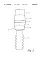
- FIG. 1shows a first part of the two-piece abutment in longitudinal cross-section
- FIG. 2is a side view of a second part of the two-piece abutment
- FIG. 3is a side view of an alternative second part having a longer post
- FIG. 4is a side view of an assembly of a second part having flutes along the post and the first part of FIG. 1;
- FIG. 5is an end view of FIG. 4;
- FIG. 6is a side view of an assembly having a longer second part with flutes and the first part of FIG. 1;
- FIGS. 7A-7Cillustrate an alternative first part which has a cylindrical outer surface
- FIGS. 8A-8Billustrate an alternative second part having a flattened side on its post
- FIGS. 9A-9Billustrate an alternative second part having a threaded bore in its post
- FIGS. 10A-10Cillustrate alternative first parts in which the exterior surface is non-round
- FIGS. 11A-11Billustrate the assembly of the first part of FIG. 7 and the second part of FIG. 9 mounted on an implant
- FIG. 12illustrates the assembly of FIG. 11 with an impression coping attached to the post
- FIG. 13illustrates the assembly of FIG. 11 with a healing cap attached to the post
- FIG. 14illustrates the assembly of FIG. 11 with a prosthetic tooth mounted on a gold cylinder that is attached to the post;
- FIG. 15illustrates a two-piece assembly with a prosthetic tooth directly attached to the post
- FIGS. 16a-16fillustrate the first part of the two-piece abutment having anti-rotational connecting structures in the socket region.
- the first part 10 shown in FIG. 1comprises a tubular body 11 having a socket 12 at its lower section 14.
- the socket 12extends upwardly into the body 11 from its lower wall 16 and has a regular polygonal (hexagonal) transverse shape for interfitting non-rotationally on a matching boss of a typical dental implant (illustrated in FIGS. 11-15).
- the lower section 14 of the body 11has an expanding transverse size as it proceeds away from the lower wall 16 and an upper section 18 of contracting transverse size as it proceeds further away from the lower wall 16. Where the lower and uppers sections 14 and 18 are joined the upper section 18 is smaller transversely than the lower section 14 which provides for a shoulder 20 facing away from the implant.
- the upper sectionhas a female locking taper 22 which opens into the socket 12.
- the female locking taper 22 and the socket 12form a part of a bore through the first part 10.
- the female locking taper 22diverges at an angle ⁇ which is generally in the range from about 5° to about 20°.
- the second part 30 shown in FIG. 2has a threaded stem 32 and a post 34 which is in three sections.
- a first section 36has a male locking taper 38 matching the female locking taper 22 of the first part 10.
- angle ⁇ in the first section 36is the same as angle ⁇ in the female locking taper 22 of the first part 10.
- An intermediate section 40is generally cylindrical.
- a third section 42has a contracting transverse section and tapers inwardly at an angle ⁇ which is typically in the range from about 5° to about 30°.
- the size of the post 34may vary based on the patient and the function for which the second part 30 is used.
- a second part 44 in FIG. 3has a post with a longer intermediate section 46.
- the postextends above the first part 10 by an amount at least as large as the height of the first part 10. In some cases, as is shown in FIG. 6, the post extends above the first part 10 by an amount roughly the same as the length of the second part below the upper edge of the first part 10.
- FIGS. 4-5illustrate a second part 30' which is similar in size and shape to the second part 30 of FIG.2.
- second part 30'includes a plurality of flutes 48 where a tool (not shown) can engage and rotate the second part 30' into the first part 10 as the threaded stem 32' is screwed into a threaded bore of an implant.
- the locking tapers 22 and 38'engage to frictionally lock the two parts 10 and 30' against relative rotation.
- the stem 32' screwed into an implant and the socket 12 non-rotationally engaged on the implantthe two-piece abutment of the invention is non-rotationally fixed to the implant.
- FIG. 6shows a longer second part 44' that is similar to the second part 44 which has a larger post and engages the first part 10 (FIG. 3).
- the male locking tapers of both second parts 44' and 30'(FIG. 4) are interchangeably the same such that both second parts 44' and 30' may be used with the same first part 10.
- first parts of different external configurationsmay be provided as is evident in FIGS. 7 and 10 below. It will be understood that the interchangeability of components in this invention lends itself to providing components in sets that may be adapted to various dental restoration tasks depending on the needs of a particular patient.
- the cliniciancan then prepare the post 34 such that it conforms to the precise height and angle of the adjacent teeth. The clinician performs this task by cutting into the surface of the post 34.
- the two-piece abutment systemcan be used in its manufactured configuration or adjusted to a unique configuration that is suited for a particular patient.
- FIGS. 7A-7Cillustrate an alternative first part 60 which has a body 61 with a substantially cylindrical outer surface 62.
- a bore 64extends through the body 61 and includes a socket region 66.
- the socket region 66is polygonal (hexagonal in this case) and includes an anti-rotational structure 68 in each of its six corners 70. These anti-rotational structures 68 arc discussed in detail below with reference to FIGS. 16a-16f.
- the bore 64also includes a locking taper region 72 and an intermediate region 74.
- the locking taper region 72engages a correspondingly shaped male taper on a post of a second part of the two-piece abutment like second parts shown in FIGS. 8-9.
- the angle of the taperis typically the same as the range given for angle ⁇ in FIG. 1.
- the style of the first part 10 in FIGS. 1-6 and the style of the first part 60 in FIGS. 7A-7Cmay be in the same dental kit such that the clinician chooses the style that is best suited for his or her patient.
- the internal taper angleis the same for the first parts 10 and 60 so that same type of second part can be utilized.
- a dental setmay include not only different styles, but it may include different sizes of each style.
- the first part 60includes a bottom surface 76 which is adjacent the socket region 66 and engages the implant. At the other end of the first part 60, a shoulder 78 resides which provides for a surface against which another component may abut. An externally tapered region 80 is at the extremity of the first part 60.
- FIGS. 8A and 8Billustrate a second part 90 that is compatible with the first part 60 in FIGS. 7A-7C.
- the second part 90includes a threaded shaft 92 which mates with an internally threaded bore of the implant.
- a male tapered portion 94is adjacent the threaded shaft 92 and matches the locking taper region 74 of the first part 60.
- An intermediate portion 95is adjacent the tapered portion 94 and is generally cylindrical.
- an upper portion 96 that reduces in cross sectionis located at the extremity of the second part 90.
- the upper portion 96has a flattened surface 98 which provides for a surface to grip when rotating the second part 90.
- the flattened surface 98also provides for the non-rotational mating with another component encompassing upper portion 96 assuming that component includes a flat interior surface that engages the flattened surface 98.
- FIGS. 9A-9Billustrate an alternative second part 100 which differs from the second part 90 in FIGS. 8A-8B only in that it contains a threaded bore 101 in its upper portion 106.
- the threaded bore 101is used to attach other components to the second part 100 as will be shown in FIGS. 12-15.
- the threaded shaft 102, the male tapered portion 104, the intermediate portion 105, and the flattened surface 108 on the upper portion 106are the same structures that are present on the second part 90 in FIGS. 8A-8B.
- FIGS. 10A-10Cillustrate yet other alternative first parts.
- FIGS. 10A and 10Billustrate a non-round shape to a first part 110.
- the body 111has an outer surface 112 that is non-round initially but then gradually changes to round in a tapered section 114 adjacent the socket 116.
- the bottom surface 118is round to mate with a cylindrical implant.
- FIG. 10Cillustrates a first part 120 which deviates from the first part 110 of FIGS. 10A-10B in two ways.
- an oval shapeis present on an exterior surface 122 of the first part 120. This oval shape also gradually changes to a round shape at the lower surface 124 so as to mate with a cylindrical implant.
- a socket 126is present that includes the shape of a twelve-pointed star that allows the first part 120 to be mounted on the hexagonal boss of an implant in twelve orientations.
- the internal structure of the first parts 110 and 120 of FIGS. 10A-10Cis the same as the previously described first parts so as to be interchangeable those devices. Expanding the dental kit to include non-round shapes offers more options to the clinician and allows him or her to select a first part that is best suited for the patient.
- FIGS. 11A-11Billustrate the first part 60 of FIG. 7 and the second part 100 of FIG. 9 mounted on an implant 130.
- the implant 130has an upper table 132 on which the lower surface 76 of the first part 60 mates.
- the socket 66 of the first part 60captures the correspondingly shaped boss 134 on the implant 130.
- the threaded shaft 102 of the second part 100is screwed into a threaded bore 136 in the implant 130, the locking tapered surfaces 104 and 72 engage and tighten.
- the torque required to complete the assembly of the first and second parts 60 and 100 on the implant 120is in the range from about 30 N ⁇ cm to about 40 N ⁇ cm.
- FIG. 12illustrates an impression coping 140 fixed on the second part 100.
- the impression coping 140has a bottom surface 142 which engages the shoulder 78 of the first part 60.
- the interior surface of the impression coping 140has a contour that matches the contour of the exterior surface of the second part 100. Thus, the interior surface has a flat region 143 to match the external flattened surface 108 of the second part 100 to resist rotation therearound.
- the impression coping 140also includes a wide-head screw 144 which threadly engages threaded bore 101 and holds the impression coping 140 on the second part 100.
- the impression coping 140includes an external flat side 146 which allows for the impression coping 140 to be properly realigned within the impression material after the impression is made.
- the coping 140can have several surfaces for non-rotationally engaging the impression material.
- the impression coping 140is a transfer coping in that after the impression is taken, the impression material is removed without the coping 140 be carried with it.
- the screw 144is removed and coping 140 is "transferred" back into the impression material with the flat surface 146 being aligned with the flat surface within the cavity of the impression material.
- the coping 140is then mounted on an analog of the implant 130 and the first and second parts 60 and 10 and a model of the region is made.
- the screw 144could be elongated with a head that extends above the impression material. After the impression material has been placed at the site, the elongated screw, which is exposed through the impression material, is unscrewed. The coping 140 would then be retained within, or "picked-up" by, the impression material when it is removed from the site. Thus, the impression coping 140 could also be used as a pick-up type impression coping.
- the second part 100 with its flat surface 108could itself be used as an impression coping. That is to say that the impression material can be placed directly over the second part 100. Then, after the impression material is removed, an angular registering mark is placed between the first part 60 and the second part 100 to ensure that they are realigned exactly on an implant analog when making the model to develop a permanent dentition. While the first and second parts 60 and 100 are removed, a temporary abutment could be placed on the implant. Alternatively, a second set of the first and second parts 60 and 100 having a healing cap (FIG. 13) or a temporary dentition (FIG. 15) could be placed on the implant until the original set is returned with a permanent dentition attached.
- a healing capFIG. 13
- a temporary dentitionFIG. 15
- FIG. 13illustrates a healing cap 150 that is placed over the second part 100.
- the healing cap 150is held on the second part 100 by a screw 152 that threadably engages the threaded hole 101.
- the screw 152is approximately flush with the upper surface of the healing cap 150.
- the healing cap 150has a lower surface 154 which engages the shoulder 78 of the first part 60.
- the interior surface of the healing cap 150includes a flat portion 156 that engages the flattened side 108 of the second part 100 to resist rotation of the healing cap 150 around the second part 100.
- FIG. 14illustrates a cylinder 160 on which a prosthetic tooth 162 is permanently mounted.
- the prosthetic tooth 162has a hole 164 at its upper end allowing a screw 166 to pass therethrough and connect the cylinder 160 to the second part 100 via the threaded bore 101.
- the cylinder 160has a lower surface 168 which abuts the shoulder 78 of the first part 60.
- the interior surface of the cylinder 160has a flat surface 170 that engages the flattened surface 108 of the second part 100. Thus, the cylinder 160 cannot rotate on the second part 100.
- the lower region of the cylinder 160 adjacent to the lower surface 168could have a series of flats that could mate with a series of flats on the externally tapered region 80 of the first part 60 for resisting rotation.
- FIG. 15illustrates the second part 90 of FIGS. 8A-8B mounted on the first part 60.
- the surface of the second part 90has been prepared to receive cement and connect the second part 90 to an artificial tooth 180.
- the artificial tooth 180may be made of an acrylic such that the clinician can modify it to fit precisely in the patient's mouth.
- the artificial tooth 180can be a permanent tooth, or it may be attached to the second part 90 via a temporary cement such that it is a temporary dentition.
- FIG. 16ais a detailed view of the first part 60 showing the corners 70 and the anti-rotational structures 68 placed thereon. Because of the tolerances in the boss of the implant and the socket, these two-pieces never fit tightly within each other. Therefore, there is always a slight rotation between the parts. Typically, when a screw holds down an abutment, the torque is used to produce tension in the screw as its threads engage the implant. In the present invention, the torque on the second part is resisted by the friction at the engaged locking tapers of the first and second parts and by the tension produced by the engaging threads. Thus, the tension in the second part is typically less (because of the friction at the locking tapers that the torque overcomes) which increases the likelihood that the first part may loosen on the implant. One option is to decrease the cross-sectional area of the second part at a neck which increases the stress and increases the strain to hold the pieces tightly together. The second part 30 in FIG. 2 has such a neck between the threaded stem 32 and the male locking taper 38.
- anti-rotational structures 68can be used that make contact with sidewalls of the hexagonal boss of the implant at its corners to prevent rotation of the implant in the socket 66.
- These anti-rotational structures 68are essentially shims located at the corners 70.
- the anti-rotational structures 68can be removed somewhat from the corners 70, as is shown in FIG. 16b. Thus, they do not have to be located directly in the corners 70.
- FIG. 16cillustrates the anti-rotational structures 68 being a corner block as opposed to being shims.
- the corner blockscome into firm contact with the hexagonal boss of the implant at the corners of the implants.
- the corner blocksare dimensioned so that opposite pairs of the blocks will squeeze the hexagonal boss between them to hold the first part 60 tightly on the implant.
- FIG. 16dshows anti-rotational structures 68 at the corners 70 which have the squeezing effect from the corner blocks as described above with reference to FIG. 16c. Additionally, the anti-rotational structures 68 have a shim-type structure which enhances the contact of anti-rotational structures 68 with the sides of the boss of the implant.
- FIG. 16eshows an anti-rotational structure 68 in still another embodiment.
- a corner blockis in the corner 70 and shims are positioned outside the corner.
- FIG. 16fshows a preferred embodiment of the invention which includes modified anti-rotational structures 68 to facilitate a smooth entrance of the hexagonal boss into the socket while still providing an anti-rotational effect.
- the improvementcan best be observed by comparing the anti-rotational structures shown in FIG. 16f to those shown in FIG. 16a.
- the corner anti-rotational structures 68have upper edges which are substantially parallel to and spaced below the upper edge of the socket. Upon initial insertion and until encountering the upper edge of the corner anti-rotational structures 68, the hexagonal boss fits within the socket with the same degree of rotational looseness as encountered in the prior art.
- each corner shim pairfacilitates entry of the boss into the socket by angling the upper edges of each corner shim pair relative to the upper edge of the socket. Specifically, the top edges of each shim pair are angled toward each other and toward the upper edge of the socket so that they meet at an apex near the upper end of a corner of the socket. As the boss is inserted into the socket, it initially encounters the same degree of rotational looseness as in the prior art, but quickly reaches the apexes of the angled shim pairs.
Landscapes
- Health & Medical Sciences (AREA)
- Oral & Maxillofacial Surgery (AREA)
- Orthopedic Medicine & Surgery (AREA)
- Dentistry (AREA)
- Epidemiology (AREA)
- Life Sciences & Earth Sciences (AREA)
- Animal Behavior & Ethology (AREA)
- General Health & Medical Sciences (AREA)
- Public Health (AREA)
- Veterinary Medicine (AREA)
- Engineering & Computer Science (AREA)
- Mechanical Engineering (AREA)
- Dental Prosthetics (AREA)
Abstract
Description
Claims (54)
Priority Applications (4)
| Application Number | Priority Date | Filing Date | Title |
|---|---|---|---|
| US08/729,869US5829977A (en) | 1995-05-25 | 1996-10-15 | Two-piece dental abutment |
| PCT/US1996/016550WO1997014372A1 (en) | 1995-10-17 | 1996-10-16 | Two-piece dental abutment |
| AU74453/96AAU7445396A (en) | 1995-10-17 | 1996-10-16 | Two-piece dental abutment |
| US09/179,493US5989026A (en) | 1995-05-25 | 1998-10-26 | Ceramic two-piece dental abutment |
Applications Claiming Priority (3)
| Application Number | Priority Date | Filing Date | Title |
|---|---|---|---|
| US08/451,083US5725375A (en) | 1995-05-25 | 1995-05-25 | Anti-rotational connecting mechanism |
| US570295P | 1995-10-17 | 1995-10-17 | |
| US08/729,869US5829977A (en) | 1995-05-25 | 1996-10-15 | Two-piece dental abutment |
Related Parent Applications (1)
| Application Number | Title | Priority Date | Filing Date |
|---|---|---|---|
| US08/451,083Continuation-In-PartUS5725375A (en) | 1995-05-25 | 1995-05-25 | Anti-rotational connecting mechanism |
Related Child Applications (1)
| Application Number | Title | Priority Date | Filing Date |
|---|---|---|---|
| US09/179,493Continuation-In-PartUS5989026A (en) | 1995-05-25 | 1998-10-26 | Ceramic two-piece dental abutment |
Publications (1)
| Publication Number | Publication Date |
|---|---|
| US5829977Atrue US5829977A (en) | 1998-11-03 |
Family
ID=26674670
Family Applications (1)
| Application Number | Title | Priority Date | Filing Date |
|---|---|---|---|
| US08/729,869Expired - LifetimeUS5829977A (en) | 1995-05-25 | 1996-10-15 | Two-piece dental abutment |
Country Status (3)
| Country | Link |
|---|---|
| US (1) | US5829977A (en) |
| AU (1) | AU7445396A (en) |
| WO (1) | WO1997014372A1 (en) |
Cited By (82)
| Publication number | Priority date | Publication date | Assignee | Title |
|---|---|---|---|---|
| US5989026A (en)* | 1995-05-25 | 1999-11-23 | Implant Innovations, Inc. | Ceramic two-piece dental abutment |
| US6068479A (en)* | 1995-02-21 | 2000-05-30 | Kwan; Norman Ho-Kwong | Dental implant system |
| US6168435B1 (en) | 1998-10-26 | 2001-01-02 | Implant Innovations, Inc. | Ceramic dental abutments with a metallic core |
| US6217331B1 (en) | 1997-10-03 | 2001-04-17 | Implant Innovations, Inc. | Single-stage implant system |
| US6447295B1 (en) | 1999-04-15 | 2002-09-10 | Nobel Biocare Ab | Diamond-like carbon coated dental retaining screws |
| USD477667S1 (en) | 2002-08-05 | 2003-07-22 | George M. Whitehead | Dental abutment |
| USD477878S1 (en) | 2002-08-05 | 2003-07-29 | George M. Whitehead | Dental abutment |
| USD477879S1 (en) | 2002-08-05 | 2003-07-29 | George M. Whitehead | Dental abutment |
| USD477876S1 (en) | 2002-08-05 | 2003-07-29 | George M. Whitehead | Dental abutment |
| USD477877S1 (en) | 2002-08-05 | 2003-07-29 | George M. Whitehead | Dental abutment |
| US20030190586A1 (en)* | 1998-02-26 | 2003-10-09 | Falk Theodore S. | Method and apparatus for isolating a work object |
| USD482450S1 (en) | 2002-08-05 | 2003-11-18 | George M. Whitehead | Dental abutment |
| USD486912S1 (en) | 2003-03-18 | 2004-02-17 | Cagenix, Inc. | Dental implant abutment |
| USD486914S1 (en) | 2003-03-18 | 2004-02-17 | Cagenix, Inc. | Dental implant abutment |
| USD487150S1 (en) | 2003-03-18 | 2004-02-24 | Cagenix, Inc. | Dental implant abutment |
| USD487153S1 (en) | 2003-03-18 | 2004-02-24 | Cagenix, Inc. | Dental implant abutment |
| USD489824S1 (en) | 2003-03-18 | 2004-05-11 | Cagenix, Inc. | Unitary dental implant |
| US20040101806A1 (en)* | 2002-09-12 | 2004-05-27 | Ajay Kumar | Dental impression coping with retention |
| US6758672B2 (en) | 2000-01-18 | 2004-07-06 | Implant Innovations, Inc. | Preparation coping for creating an accurate permanent post to support a final prosthesis and method for creating the same |
| USD493890S1 (en) | 2003-03-18 | 2004-08-03 | Cagenix, Inc. | Dental implant abutment |
| US20040185419A1 (en)* | 2003-03-18 | 2004-09-23 | Schulter Carl W. | Unitary dental implant |
| US20040185420A1 (en)* | 2003-03-18 | 2004-09-23 | Schulter Carl W. | Dental implant abutment |
| US20040185417A1 (en)* | 2003-03-18 | 2004-09-23 | Jeff Rassoli | Rotationally immobilized dental implant and abutment system |
| KR100540447B1 (en)* | 2004-02-20 | 2006-01-10 | (주) 코웰메디 | Crown type implant |
| USRE38945E1 (en) | 1995-01-30 | 2006-01-24 | Paula S. Fried | Dental implants and methods for extending service life |
| KR100545852B1 (en)* | 2002-10-17 | 2006-01-31 | (주) 코웰메디 | Abutments for Bridge Implants |
| KR100545853B1 (en)* | 2002-10-17 | 2006-01-31 | (주) 코웰메디 | Abutments for Crown Implants |
| WO2007093648A1 (en)* | 2006-02-16 | 2007-08-23 | Francisco Javier Garcia Saban | Dental implant assembly and device for taking a dental impression |
| USD556907S1 (en) | 2006-02-21 | 2007-12-04 | Jeff Rassoli | Dental prosthesis implant |
| USD562454S1 (en) | 2006-02-21 | 2008-02-19 | Jeff Rassoli | Prosthetic dental implant |
| USD562453S1 (en) | 2006-02-21 | 2008-02-19 | Jeff Rassoli | Prosthetic dental abutment |
| USD562455S1 (en) | 2006-02-21 | 2008-02-19 | Jeff Rassoli | Dental prosthesis abutment |
| US7338286B2 (en) | 2002-11-13 | 2008-03-04 | Biomet 3I, Inc. | Dental implant system |
| US20080233539A1 (en)* | 2005-08-22 | 2008-09-25 | Hans-Dieter Rossler | Abutment For a Tooth Implant |
| US20080241792A1 (en)* | 2005-08-22 | 2008-10-02 | Hans-Dieter Rossler | Tooth Implant |
| US20080293012A1 (en)* | 2005-11-23 | 2008-11-27 | Chaves Branca Fraga De Resende | Splint Abutment Over Osseointegrated Implant and Compensatory Slated Coping |
| FR2916341A1 (en)* | 2007-07-30 | 2008-11-28 | Gilbert Ouaknine | Cylindrical inlaycore's obturator for dental implantology field, has external screw thread and internal screw thread that are cooperated with external screw thread and internal screw thread of inlaycore, respectively |
| US20090029313A1 (en)* | 2007-07-25 | 2009-01-29 | Cheng Yih Trading Co., Ltd. | Simplified implant cap for tooth implant |
| US20090197218A1 (en)* | 2008-02-05 | 2009-08-06 | Joseph Wiener | Universal transitional abutment |
| US20090291412A1 (en)* | 2007-03-06 | 2009-11-26 | Kent Engstrom | Dental implant, abutment structure and method for implanting a dental implant |
| US7632095B2 (en) | 2007-08-13 | 2009-12-15 | Biomet 3I, Inc. | Method for forming a dental prosthesis |
| US20100081111A1 (en)* | 2008-09-29 | 2010-04-01 | Maxillent Ltd. | Sinus lift implant |
| US20100255446A1 (en)* | 2008-09-29 | 2010-10-07 | Hadar Better | Implants, tools, and methods for sinus lift and bone augmentation |
| US20100311013A1 (en)* | 2005-02-11 | 2010-12-09 | Niznick Gerald A | One-piece, screw-receiving, externally-threaded endosseous dental implants and related transfer components, comfort caps and abutments |
| US20110104637A1 (en)* | 2009-11-05 | 2011-05-05 | Dentatus, Usa, Ltd. | Variably mountable implant with stepped socket |
| US8029284B2 (en) | 2008-09-29 | 2011-10-04 | Maxillent Ltd. | Implants, tools, and methods for sinus lift and lateral ridge augmentation |
| US8033826B2 (en) | 2007-11-15 | 2011-10-11 | Biomet 3I, Llc | Two-piece dental abutment system |
| US20110287381A1 (en)* | 2009-02-04 | 2011-11-24 | Mid Corp. | System, method and apparatus for implementing dental implants |
| US20120077150A1 (en)* | 2010-09-23 | 2012-03-29 | Biomet 3I, Llc | Dental abutment system |
| US20140045145A1 (en)* | 2011-04-20 | 2014-02-13 | Redtenbacher Praezisionsteile Ges.M.B.H. | Dental prosthesis |
| US8662891B2 (en) | 2008-09-29 | 2014-03-04 | Maxillent Ltd. | Implants, tools, and methods for sinus lift and lateral ridge augmentation |
| US8668495B2 (en) | 2006-02-24 | 2014-03-11 | Zimmer, Inc. | Ceramic/metallic dental abutment |
| US8702423B2 (en) | 2011-12-08 | 2014-04-22 | Maxillent Ltd. | Cortical drilling |
| US8721334B2 (en) | 2009-06-16 | 2014-05-13 | Maxillent Ltd. | Dental implements having end mill cutter surfaces |
| US9283057B2 (en) | 2011-02-02 | 2016-03-15 | Mid Corp. | System, apparatus and method for implementing implants |
| US20160074141A1 (en)* | 2014-09-12 | 2016-03-17 | Italo Lozada | Dental Prosthesis |
| US20160193016A1 (en)* | 2015-01-07 | 2016-07-07 | Bicon, Llc | Integrated Dental Implant Abutments |
| US20160213451A1 (en)* | 2014-05-27 | 2016-07-28 | Ivoclar Vivadent Ag | Dental prosthesis production device and dental prosthesis |
| US9468506B2 (en) | 2011-12-30 | 2016-10-18 | Nobel Biocare Services Ag | Abutment position locator |
| US9662186B2 (en) | 2012-12-21 | 2017-05-30 | Nobel Biocare Services Ag | Dental component with metal adapter |
| WO2017090037A1 (en)* | 2015-11-26 | 2017-06-01 | Mis Implants Technologies Ltd | Abutment, coping and method of connecting thereof in a dental multi-unit system |
| US9668833B2 (en) | 2012-12-21 | 2017-06-06 | Nobel Biocare Services Ag | Abutment and method of attaching an abutment to a dental implant |
| US20170202649A1 (en)* | 2014-07-25 | 2017-07-20 | Nobel Biocare Services Ag | Provisional prosthetic systems and methods of using same |
| US9730774B2 (en) | 2015-04-22 | 2017-08-15 | Maxillent Ltd. | Bone graft injection device |
| US9795467B2 (en) | 2012-07-20 | 2017-10-24 | Pavel Krastev | Apparatus and method for sinus lift procedure |
| US20180049849A1 (en)* | 2016-08-20 | 2018-02-22 | Hybridge Dental Lab LLC | Digital full arch apparatus and method for immediate definitive dental prostheses |
| US9925024B2 (en) | 2011-06-28 | 2018-03-27 | Biomet 3I, Llc | Dental implant and abutment tools |
| US20180325631A1 (en)* | 2015-11-20 | 2018-11-15 | Nobel Biocare Services Ag | Healing cap with scannable features |
| WO2018220612A1 (en) | 2017-05-29 | 2018-12-06 | MIS Implants Technologies Ltd. | Dental connection system |
| US10149741B2 (en) | 2012-12-21 | 2018-12-11 | Nobel Biocare Services Ag | Method of attaching a dental component to a dental implant |
| USD840038S1 (en) | 2017-09-05 | 2019-02-05 | MIS Implants Technologies Ltd. | Dental connector |
| USD840037S1 (en) | 2017-09-05 | 2019-02-05 | MIS Implants Technologies Ltd. | Dental connector |
| USD840039S1 (en) | 2017-09-05 | 2019-02-05 | MIS Implants Technologies Ltd. | Dental connector |
| US20190142552A1 (en)* | 2017-11-11 | 2019-05-16 | Jiachang Zhang | Gingival cone collars for dental implants |
| US10441387B2 (en) | 2012-07-09 | 2019-10-15 | Nobel Biocare Services Ag | Abutment system and dental methods |
| WO2020079684A1 (en)* | 2018-10-14 | 2020-04-23 | Abracadabra Implants Ltd | Dental implant device and system |
| US10682210B1 (en) | 2016-08-20 | 2020-06-16 | Hybridge, Llc | Digital full arch method for immediate definitive dental prostheses |
| US11045286B2 (en) | 2014-04-22 | 2021-06-29 | Noga Medical Products Ltd. | Dental implants |
| US20210378798A1 (en)* | 2018-10-09 | 2021-12-09 | Ennio CALABRIA | Dental implant system |
| US11311354B2 (en) | 2018-10-09 | 2022-04-26 | Smart Denture Conversions, Llc | Screw-attached pick-up dental coping system and methods |
| US11766169B2 (en)* | 2019-11-04 | 2023-09-26 | Implant Solutions Pty Ltd | Apparatus for facilitating acquisition of a scan and intraoral scanning procedures |
| US11957538B2 (en) | 2021-12-23 | 2024-04-16 | Smart Denture Conversions, Llc | Screw-attached pick-up dental coping system, methods and accessories |
Families Citing this family (7)
| Publication number | Priority date | Publication date | Assignee | Title |
|---|---|---|---|---|
| SE9702981D0 (en)* | 1997-08-19 | 1997-08-19 | Astra Ab | Dental implant systems |
| EP1502558B1 (en) | 1997-10-03 | 2008-01-23 | Biomet 3I, Inc. | Single-stage implant system |
| FR2806903B1 (en) | 2000-03-31 | 2003-05-02 | Jean Claude Yeung | DENTAL PROSTHESIS |
| ES2204267B1 (en)* | 2002-01-17 | 2005-03-01 | Implant Microdent System, S.L. | DEVICE FOR THE SETTING OF DENTAL PROTESIS. |
| SE522501C2 (en) | 2002-06-27 | 2004-02-10 | Nobel Biocare Ab | Preferably completely spaced ceramic spacer with adapter |
| US8867800B2 (en)* | 2009-05-27 | 2014-10-21 | James R. Glidewell Dental Ceramics, Inc. | Method of designing and fabricating patient-specific restorations from intra-oral scanning of a digital impression |
| CN106510869A (en)* | 2015-09-09 | 2017-03-22 | 昱擎科技股份有限公司 | Dental implant |
Citations (42)
| Publication number | Priority date | Publication date | Assignee | Title |
|---|---|---|---|---|
| DE2114323A1 (en)* | 1970-03-25 | 1971-10-14 | Aga Ab | Implantable fasteners for prostheses and the like. |
| GB1291470A (en)* | 1968-12-09 | 1972-10-04 | Aga Ab | A device for mounting a prosthesis on skeletal tissue |
| US3958471A (en)* | 1972-02-08 | 1976-05-25 | Paul-Heinz Wagner Maschinenfabrikation | Method of and apparatus for manufacturing workpieces having polygonyl inner and outer contours |
| US4011602A (en)* | 1975-10-06 | 1977-03-15 | Battelle Memorial Institute | Porous expandable device for attachment to bone tissue |
| US4177562A (en)* | 1977-05-02 | 1979-12-11 | Miller Alvin L | Dental implant and method of inserting the same |
| WO1985002337A1 (en)* | 1983-11-25 | 1985-06-06 | Soederberg Per Olof | Implant for attachment of dental prostheses |
| US4547157A (en)* | 1983-04-20 | 1985-10-15 | Miter, Inc. | Submergible post-type dental implant system and method of using same |
| US4624673A (en)* | 1982-01-21 | 1986-11-25 | United States Medical Corporation | Device system for dental prosthesis fixation to bone |
| DE3531389A1 (en)* | 1985-09-03 | 1987-03-05 | Kirsch Axel | ENOSSAL IMPLANT |
| US4713004A (en)* | 1986-09-04 | 1987-12-15 | Vent Plant Corporation | Submergible screw-type dental implant and method of utilization |
| US4738623A (en)* | 1986-08-15 | 1988-04-19 | Quintron, Inc. | Dental implant and method |
| US4872839A (en)* | 1987-06-12 | 1989-10-10 | Nobelpharma Ab | Spacer for dental implants |
| US4988297A (en)* | 1988-03-01 | 1991-01-29 | Implant Innovations, Inc. | Alignment corrector for dental implants |
| US5035619A (en)* | 1989-10-20 | 1991-07-30 | Fereidoun Daftary | Anatomical restoration dental implant system with improved healing cap and abutment |
| US5071351A (en)* | 1986-07-02 | 1991-12-10 | Collagen Corporation | Dental implant system |
| US5073111A (en)* | 1989-10-20 | 1991-12-17 | Fereidoun Daftary | Anatomical restoration dental implant system |
| DE4028855A1 (en)* | 1989-05-31 | 1992-03-12 | Eberle Medizintech Elemente | Tooth implant protected against rotation - has post connected by screw union with base body, and distance socket with centering connection |
| US5100323A (en)* | 1990-09-05 | 1992-03-31 | Impla-Med Incorporated | Dental implant |
| US5104318A (en)* | 1990-09-20 | 1992-04-14 | 2848-4293 Quebec Inc. | Implant assembly for anchoring an artificial tooth |
| US5122059A (en)* | 1990-09-08 | 1992-06-16 | Eberle Medizintechnische Element Gmbh | Enossal implant for a firmly seated tooth replacement |
| US5125839A (en)* | 1990-09-28 | 1992-06-30 | Abraham Ingber | Dental implant system |
| US5135395A (en)* | 1990-07-05 | 1992-08-04 | Marlin Gerald M | Implant collar and post system |
| US5169308A (en)* | 1989-12-22 | 1992-12-08 | Ab John Sjoding | Device for tooth implantation |
| US5195892A (en)* | 1990-07-23 | 1993-03-23 | Odontit S.A. | Bone-integrated dental implant system |
| US5197881A (en)* | 1991-12-30 | 1993-03-30 | Wellesley Research Associates, Inc. | Dental implant system and apparatus |
| US5209659A (en)* | 1990-09-05 | 1993-05-11 | Impla-Med Incorporated | Method for installing a dental implant |
| US5286195A (en)* | 1989-12-07 | 1994-02-15 | Zl Microdent-Attachment Gmbh | Screw element for threadedly connecting a multi-part dental prosthesis |
| US5297963A (en)* | 1993-05-17 | 1994-03-29 | Fereidoun Dafatry | Anatomical restoration dental implant system with interlockable elliptical healing cap assembly and matching abutment member |
| US5334024A (en)* | 1990-03-21 | 1994-08-02 | Core-Vent Corporation | Transfer abutment |
| US5344457A (en)* | 1986-05-19 | 1994-09-06 | The University Of Toronto Innovations Foundation | Porous surfaced implant |
| US5350300A (en)* | 1989-11-08 | 1994-09-27 | Jacques Gallais | Dental implant |
| US5362235A (en)* | 1993-05-17 | 1994-11-08 | Fereidoun Daftary | Anatomical restoration dental implant system with interlockable angled abutment assembly |
| US5362234A (en)* | 1993-09-21 | 1994-11-08 | Alfred Salazar | Self-drilling endosteal hollow-basket implant system with shock-absorber |
| US5368483A (en)* | 1993-06-14 | 1994-11-29 | Institut Straumann Ag | Device-for fixing a dental prosthesis to a jaw bone |
| US5417570A (en)* | 1994-01-03 | 1995-05-23 | Zest Anchors, Inc. | Dental anchor assembly |
| US5431567A (en)* | 1993-05-17 | 1995-07-11 | Daftary; Fereidoun | Anatomical restoration dental implant system with interlockable various shaped healing cap assembly and matching abutment member |
| US5433606A (en)* | 1993-07-28 | 1995-07-18 | Core-Vent Corporation | Interlocking, multi-part endosseous dental implant systems |
| US5437551A (en)* | 1991-12-30 | 1995-08-01 | Wellesley Research Associates, Inc. | Dental implant post and prosthesis construction |
| US5533898A (en)* | 1993-11-18 | 1996-07-09 | Mena; Raul | Dental implant device |
| US5538426A (en)* | 1992-04-16 | 1996-07-23 | Stewart Peter Harding | Method of forming a dental prosthesis for mounting in an implant, a method of forming a dental model for use therein, a dental formation mounting arrangement |
| US5564924A (en)* | 1995-02-21 | 1996-10-15 | Kwan; Norman H. | Hexagonal abutment implant system |
| US5588838A (en)* | 1992-10-28 | 1996-12-31 | Astra Aktiebolag | Fixture for use in a dental implant system |
- 1996
- 1996-10-15USUS08/729,869patent/US5829977A/ennot_activeExpired - Lifetime
- 1996-10-16AUAU74453/96Apatent/AU7445396A/ennot_activeAbandoned
- 1996-10-16WOPCT/US1996/016550patent/WO1997014372A1/enactiveApplication Filing
Patent Citations (46)
| Publication number | Priority date | Publication date | Assignee | Title |
|---|---|---|---|---|
| GB1291470A (en)* | 1968-12-09 | 1972-10-04 | Aga Ab | A device for mounting a prosthesis on skeletal tissue |
| DE2114323A1 (en)* | 1970-03-25 | 1971-10-14 | Aga Ab | Implantable fasteners for prostheses and the like. |
| US3958471A (en)* | 1972-02-08 | 1976-05-25 | Paul-Heinz Wagner Maschinenfabrikation | Method of and apparatus for manufacturing workpieces having polygonyl inner and outer contours |
| US4011602A (en)* | 1975-10-06 | 1977-03-15 | Battelle Memorial Institute | Porous expandable device for attachment to bone tissue |
| US4177562A (en)* | 1977-05-02 | 1979-12-11 | Miller Alvin L | Dental implant and method of inserting the same |
| US4624673A (en)* | 1982-01-21 | 1986-11-25 | United States Medical Corporation | Device system for dental prosthesis fixation to bone |
| US4547157A (en)* | 1983-04-20 | 1985-10-15 | Miter, Inc. | Submergible post-type dental implant system and method of using same |
| US4772204A (en)* | 1983-11-25 | 1988-09-20 | Astra Meditec Aktiebolag | Implant for attachment of dental prostheses |
| WO1985002337A1 (en)* | 1983-11-25 | 1985-06-06 | Soederberg Per Olof | Implant for attachment of dental prostheses |
| DE3531389A1 (en)* | 1985-09-03 | 1987-03-05 | Kirsch Axel | ENOSSAL IMPLANT |
| US5344457A (en)* | 1986-05-19 | 1994-09-06 | The University Of Toronto Innovations Foundation | Porous surfaced implant |
| US5071351A (en)* | 1986-07-02 | 1991-12-10 | Collagen Corporation | Dental implant system |
| US4738623A (en)* | 1986-08-15 | 1988-04-19 | Quintron, Inc. | Dental implant and method |
| US4713004A (en)* | 1986-09-04 | 1987-12-15 | Vent Plant Corporation | Submergible screw-type dental implant and method of utilization |
| US4872839A (en)* | 1987-06-12 | 1989-10-10 | Nobelpharma Ab | Spacer for dental implants |
| US4988297A (en)* | 1988-03-01 | 1991-01-29 | Implant Innovations, Inc. | Alignment corrector for dental implants |
| DE4028855A1 (en)* | 1989-05-31 | 1992-03-12 | Eberle Medizintech Elemente | Tooth implant protected against rotation - has post connected by screw union with base body, and distance socket with centering connection |
| US5035619A (en)* | 1989-10-20 | 1991-07-30 | Fereidoun Daftary | Anatomical restoration dental implant system with improved healing cap and abutment |
| US5073111A (en)* | 1989-10-20 | 1991-12-17 | Fereidoun Daftary | Anatomical restoration dental implant system |
| US5145372A (en)* | 1989-10-20 | 1992-09-08 | Fereidoun Daftary | Anatomical restoration dental implant system with reinforced healing cap and abutment |
| US5350300A (en)* | 1989-11-08 | 1994-09-27 | Jacques Gallais | Dental implant |
| US5286195A (en)* | 1989-12-07 | 1994-02-15 | Zl Microdent-Attachment Gmbh | Screw element for threadedly connecting a multi-part dental prosthesis |
| US5169308A (en)* | 1989-12-22 | 1992-12-08 | Ab John Sjoding | Device for tooth implantation |
| US5334024A (en)* | 1990-03-21 | 1994-08-02 | Core-Vent Corporation | Transfer abutment |
| US5135395A (en)* | 1990-07-05 | 1992-08-04 | Marlin Gerald M | Implant collar and post system |
| US5195892A (en)* | 1990-07-23 | 1993-03-23 | Odontit S.A. | Bone-integrated dental implant system |
| US5209659A (en)* | 1990-09-05 | 1993-05-11 | Impla-Med Incorporated | Method for installing a dental implant |
| US5100323A (en)* | 1990-09-05 | 1992-03-31 | Impla-Med Incorporated | Dental implant |
| US5122059A (en)* | 1990-09-08 | 1992-06-16 | Eberle Medizintechnische Element Gmbh | Enossal implant for a firmly seated tooth replacement |
| US5104318A (en)* | 1990-09-20 | 1992-04-14 | 2848-4293 Quebec Inc. | Implant assembly for anchoring an artificial tooth |
| US5125839A (en)* | 1990-09-28 | 1992-06-30 | Abraham Ingber | Dental implant system |
| US5437551A (en)* | 1991-12-30 | 1995-08-01 | Wellesley Research Associates, Inc. | Dental implant post and prosthesis construction |
| US5197881A (en)* | 1991-12-30 | 1993-03-30 | Wellesley Research Associates, Inc. | Dental implant system and apparatus |
| US5538426A (en)* | 1992-04-16 | 1996-07-23 | Stewart Peter Harding | Method of forming a dental prosthesis for mounting in an implant, a method of forming a dental model for use therein, a dental formation mounting arrangement |
| US5588838A (en)* | 1992-10-28 | 1996-12-31 | Astra Aktiebolag | Fixture for use in a dental implant system |
| US5476382A (en)* | 1993-05-17 | 1995-12-19 | Daftary; Fereidoun | Anatomical restoration dental implant system with interlockable various shaped healing cap assembly and matching abutment member |
| US5431567A (en)* | 1993-05-17 | 1995-07-11 | Daftary; Fereidoun | Anatomical restoration dental implant system with interlockable various shaped healing cap assembly and matching abutment member |
| US5362235A (en)* | 1993-05-17 | 1994-11-08 | Fereidoun Daftary | Anatomical restoration dental implant system with interlockable angled abutment assembly |
| US5547377A (en)* | 1993-05-17 | 1996-08-20 | Daftary; Fereidoun | Anatomical restoration dental implant system with interlockable various shaped healing cap assembly and matching abutment member |
| US5297963A (en)* | 1993-05-17 | 1994-03-29 | Fereidoun Dafatry | Anatomical restoration dental implant system with interlockable elliptical healing cap assembly and matching abutment member |
| US5368483A (en)* | 1993-06-14 | 1994-11-29 | Institut Straumann Ag | Device-for fixing a dental prosthesis to a jaw bone |
| US5433606A (en)* | 1993-07-28 | 1995-07-18 | Core-Vent Corporation | Interlocking, multi-part endosseous dental implant systems |
| US5362234A (en)* | 1993-09-21 | 1994-11-08 | Alfred Salazar | Self-drilling endosteal hollow-basket implant system with shock-absorber |
| US5533898A (en)* | 1993-11-18 | 1996-07-09 | Mena; Raul | Dental implant device |
| US5417570A (en)* | 1994-01-03 | 1995-05-23 | Zest Anchors, Inc. | Dental anchor assembly |
| US5564924A (en)* | 1995-02-21 | 1996-10-15 | Kwan; Norman H. | Hexagonal abutment implant system |
Non-Patent Citations (8)
| Title |
|---|
| "1989 Core-Vent Implant Symposium," Core-Vent Corporation, Mar. 1988 (2 pages). |
| "EsthetiCone™ systeM Components," Undated (1 page). |
| 1989 Core Vent Implant Symposium, Core Vent Corporation, Mar. 1988 (2 pages).* |
| Adell et al., "A 15-year Study of Osseointegrated Implants in the Treatment of the Endentulous Jaw," Int. J. Oral Surg., 1981, pp. 387-416. |
| Adell et al., A 15 year Study of Osseointegrated Implants in the Treatment of the Endentulous Jaw, Int. J. Oral Surg. , 1981, pp. 387 416.* |
| EsthetiCone systeM Components, Undated (1 page).* |
| New Bio Esthetic Technique Manual, Abutment Selection and Modification Guide, Steri Oss Inc., 1995 (6 pages).* |
| New Bio-Esthetic™ Technique Manual, "Abutment Selection and Modification Guide," Steri-Oss Inc., 1995 (6 pages). |
Cited By (138)
| Publication number | Priority date | Publication date | Assignee | Title |
|---|---|---|---|---|
| USRE38945E1 (en) | 1995-01-30 | 2006-01-24 | Paula S. Fried | Dental implants and methods for extending service life |
| US6068479A (en)* | 1995-02-21 | 2000-05-30 | Kwan; Norman Ho-Kwong | Dental implant system |
| US5989026A (en)* | 1995-05-25 | 1999-11-23 | Implant Innovations, Inc. | Ceramic two-piece dental abutment |
| US6217331B1 (en) | 1997-10-03 | 2001-04-17 | Implant Innovations, Inc. | Single-stage implant system |
| US6394809B2 (en) | 1997-10-03 | 2002-05-28 | Implant Innovations, Inc. | Single-stage implant system |
| US20030190586A1 (en)* | 1998-02-26 | 2003-10-09 | Falk Theodore S. | Method and apparatus for isolating a work object |
| US7922488B2 (en)* | 1998-02-26 | 2011-04-12 | Institut Straumann Ag | Method and apparatus for isolating a work object |
| US6168435B1 (en) | 1998-10-26 | 2001-01-02 | Implant Innovations, Inc. | Ceramic dental abutments with a metallic core |
| US6343930B1 (en) | 1998-10-26 | 2002-02-05 | Implant Innovations, Inc. | Ceramic dental abutments with a metallic core |
| US6447295B1 (en) | 1999-04-15 | 2002-09-10 | Nobel Biocare Ab | Diamond-like carbon coated dental retaining screws |
| US6758672B2 (en) | 2000-01-18 | 2004-07-06 | Implant Innovations, Inc. | Preparation coping for creating an accurate permanent post to support a final prosthesis and method for creating the same |
| US8002547B2 (en) | 2000-01-18 | 2011-08-23 | Biomet 3I Llc | Preparation coping for creating an accurate permanent post to support a final prosthesis and method for creating the same |
| USD477667S1 (en) | 2002-08-05 | 2003-07-22 | George M. Whitehead | Dental abutment |
| USD477877S1 (en) | 2002-08-05 | 2003-07-29 | George M. Whitehead | Dental abutment |
| USD477876S1 (en) | 2002-08-05 | 2003-07-29 | George M. Whitehead | Dental abutment |
| USD482450S1 (en) | 2002-08-05 | 2003-11-18 | George M. Whitehead | Dental abutment |
| USD477879S1 (en) | 2002-08-05 | 2003-07-29 | George M. Whitehead | Dental abutment |
| USD477878S1 (en) | 2002-08-05 | 2003-07-29 | George M. Whitehead | Dental abutment |
| US7066736B2 (en) | 2002-09-12 | 2006-06-27 | Zimmer Dental, Inc. | Dental impression coping with retention |
| US20040101806A1 (en)* | 2002-09-12 | 2004-05-27 | Ajay Kumar | Dental impression coping with retention |
| KR100545852B1 (en)* | 2002-10-17 | 2006-01-31 | (주) 코웰메디 | Abutments for Bridge Implants |
| KR100545853B1 (en)* | 2002-10-17 | 2006-01-31 | (주) 코웰메디 | Abutments for Crown Implants |
| US8636511B2 (en) | 2002-11-13 | 2014-01-28 | Biomet 3I, Llc | Dental implant system |
| US7484959B2 (en) | 2002-11-13 | 2009-02-03 | Biomet 3I, Llc | Dental implant system |
| US7338286B2 (en) | 2002-11-13 | 2008-03-04 | Biomet 3I, Inc. | Dental implant system |
| US9931182B2 (en) | 2002-11-13 | 2018-04-03 | Biomet 3I, Llc | Dental implant system |
| US9883927B2 (en) | 2002-11-13 | 2018-02-06 | Biomet 3I, Llc | Dental implant system |
| US9549793B2 (en) | 2002-11-13 | 2017-01-24 | Biomet 3I, Llc | Dental implant system |
| USD486914S1 (en) | 2003-03-18 | 2004-02-17 | Cagenix, Inc. | Dental implant abutment |
| US20040185417A1 (en)* | 2003-03-18 | 2004-09-23 | Jeff Rassoli | Rotationally immobilized dental implant and abutment system |
| US7104797B2 (en) | 2003-03-18 | 2006-09-12 | Jeff Rassoli | Rotationally immobilized dental implant and abutment system |
| US7179088B2 (en) | 2003-03-18 | 2007-02-20 | Cagenix, Inc. | Lobed dental implant |
| USD493890S1 (en) | 2003-03-18 | 2004-08-03 | Cagenix, Inc. | Dental implant abutment |
| USD486912S1 (en) | 2003-03-18 | 2004-02-17 | Cagenix, Inc. | Dental implant abutment |
| US20040185420A1 (en)* | 2003-03-18 | 2004-09-23 | Schulter Carl W. | Dental implant abutment |
| USD487150S1 (en) | 2003-03-18 | 2004-02-24 | Cagenix, Inc. | Dental implant abutment |
| USD487153S1 (en) | 2003-03-18 | 2004-02-24 | Cagenix, Inc. | Dental implant abutment |
| US20040185419A1 (en)* | 2003-03-18 | 2004-09-23 | Schulter Carl W. | Unitary dental implant |
| USD489824S1 (en) | 2003-03-18 | 2004-05-11 | Cagenix, Inc. | Unitary dental implant |
| KR100540447B1 (en)* | 2004-02-20 | 2006-01-10 | (주) 코웰메디 | Crown type implant |
| US20100311013A1 (en)* | 2005-02-11 | 2010-12-09 | Niznick Gerald A | One-piece, screw-receiving, externally-threaded endosseous dental implants and related transfer components, comfort caps and abutments |
| US8118596B2 (en)* | 2005-02-11 | 2012-02-21 | Niznick Gerald A | One-piece, screw-receiving, externally-threaded endosseous dental implants and related transfer components, comfort caps and abutments |
| US20080241792A1 (en)* | 2005-08-22 | 2008-10-02 | Hans-Dieter Rossler | Tooth Implant |
| US20080233539A1 (en)* | 2005-08-22 | 2008-09-25 | Hans-Dieter Rossler | Abutment For a Tooth Implant |
| US8632336B2 (en) | 2005-08-22 | 2014-01-21 | Riemser Pharma Gmbh | Tooth implant |
| US9039416B2 (en)* | 2005-11-23 | 2015-05-26 | Itp—Instituto De Techologia E Pesquisa Ltda | Splint abutment over osseointegrated implant and compensatory slanted coping |
| US20080293012A1 (en)* | 2005-11-23 | 2008-11-27 | Chaves Branca Fraga De Resende | Splint Abutment Over Osseointegrated Implant and Compensatory Slated Coping |
| WO2007093648A1 (en)* | 2006-02-16 | 2007-08-23 | Francisco Javier Garcia Saban | Dental implant assembly and device for taking a dental impression |
| US20090035721A1 (en)* | 2006-02-16 | 2009-02-05 | Francisco Javier Garcia Saban | Dental implant and dental impression-taking device assembly |
| USD562453S1 (en) | 2006-02-21 | 2008-02-19 | Jeff Rassoli | Prosthetic dental abutment |
| USD556907S1 (en) | 2006-02-21 | 2007-12-04 | Jeff Rassoli | Dental prosthesis implant |
| USD562454S1 (en) | 2006-02-21 | 2008-02-19 | Jeff Rassoli | Prosthetic dental implant |
| USD562455S1 (en) | 2006-02-21 | 2008-02-19 | Jeff Rassoli | Dental prosthesis abutment |
| US8668495B2 (en) | 2006-02-24 | 2014-03-11 | Zimmer, Inc. | Ceramic/metallic dental abutment |
| US8057229B2 (en) | 2007-03-06 | 2011-11-15 | Astra Tech Ab | Dental implant, abutment structure and method for implanting a dental implant |
| EP2368519A1 (en)* | 2007-03-06 | 2011-09-28 | Astra Tech AB | Dental implant, abutment structure and method for implanting a dental implant |
| US20090291412A1 (en)* | 2007-03-06 | 2009-11-26 | Kent Engstrom | Dental implant, abutment structure and method for implanting a dental implant |
| US20090029313A1 (en)* | 2007-07-25 | 2009-01-29 | Cheng Yih Trading Co., Ltd. | Simplified implant cap for tooth implant |
| FR2916341A1 (en)* | 2007-07-30 | 2008-11-28 | Gilbert Ouaknine | Cylindrical inlaycore's obturator for dental implantology field, has external screw thread and internal screw thread that are cooperated with external screw thread and internal screw thread of inlaycore, respectively |
| US7632095B2 (en) | 2007-08-13 | 2009-12-15 | Biomet 3I, Inc. | Method for forming a dental prosthesis |
| US8425230B2 (en) | 2007-11-15 | 2013-04-23 | Biomet 3I, Llc | Two-piece dental abutment system |
| US8033826B2 (en) | 2007-11-15 | 2011-10-11 | Biomet 3I, Llc | Two-piece dental abutment system |
| US9044289B2 (en) | 2008-02-05 | 2015-06-02 | Joseph Wiener | Universal transitional abutment |
| WO2009100044A3 (en)* | 2008-02-05 | 2009-10-01 | Joseph Wiener | Universal transitional abutment |
| US20090197218A1 (en)* | 2008-02-05 | 2009-08-06 | Joseph Wiener | Universal transitional abutment |
| US8029284B2 (en) | 2008-09-29 | 2011-10-04 | Maxillent Ltd. | Implants, tools, and methods for sinus lift and lateral ridge augmentation |
| US8388343B2 (en) | 2008-09-29 | 2013-03-05 | Maxillent Ltd. | Implants, tools, and methods for sinus lift and bone augmentation |
| US20100255446A1 (en)* | 2008-09-29 | 2010-10-07 | Hadar Better | Implants, tools, and methods for sinus lift and bone augmentation |
| US8556627B2 (en) | 2008-09-29 | 2013-10-15 | Maxillent Ltd. | Dental implant having a recessed surface for sealing |
| US20110212415A1 (en)* | 2008-09-29 | 2011-09-01 | Maxillent Ltd. | Sinus lift implant |
| EP3150164A1 (en) | 2008-09-29 | 2017-04-05 | Maxillent Ltd. | Apparatus for sinus lift and lateral ridge augmentation |
| US20100081111A1 (en)* | 2008-09-29 | 2010-04-01 | Maxillent Ltd. | Sinus lift implant |
| US8662891B2 (en) | 2008-09-29 | 2014-03-04 | Maxillent Ltd. | Implants, tools, and methods for sinus lift and lateral ridge augmentation |
| US7934929B2 (en) | 2008-09-29 | 2011-05-03 | Maxillent Ltd. | Sinus lift implant |
| US8696354B2 (en) | 2008-09-29 | 2014-04-15 | Maxillent Ltd. | Dental implement having lumen and distal threading |
| US8356994B2 (en) | 2008-09-29 | 2013-01-22 | Maxillent Ltd. | Sinus lift implant |
| US8827704B2 (en)* | 2009-02-04 | 2014-09-09 | Mid Corp | System, method and apparatus for implementing dental implants |
| US20110287381A1 (en)* | 2009-02-04 | 2011-11-24 | Mid Corp. | System, method and apparatus for implementing dental implants |
| US8721334B2 (en) | 2009-06-16 | 2014-05-13 | Maxillent Ltd. | Dental implements having end mill cutter surfaces |
| US20110104637A1 (en)* | 2009-11-05 | 2011-05-05 | Dentatus, Usa, Ltd. | Variably mountable implant with stepped socket |
| WO2011056323A3 (en)* | 2009-11-05 | 2011-10-06 | Dentatus Usa Ltd. | Variably mountable implant with stepped socket |
| US8888486B2 (en)* | 2010-09-23 | 2014-11-18 | Biomet 3I, Llc | Dental abutment system |
| US9717571B2 (en) | 2010-09-23 | 2017-08-01 | Biomet 3I, Llc | Dental abutment system |
| US20120077150A1 (en)* | 2010-09-23 | 2012-03-29 | Biomet 3I, Llc | Dental abutment system |
| US9283057B2 (en) | 2011-02-02 | 2016-03-15 | Mid Corp. | System, apparatus and method for implementing implants |
| US8951042B2 (en)* | 2011-04-20 | 2015-02-10 | Redtenbacher Praezisionsteile Ges.M.B.H. | Dental prosthesis |
| US20140045145A1 (en)* | 2011-04-20 | 2014-02-13 | Redtenbacher Praezisionsteile Ges.M.B.H. | Dental prosthesis |
| US10952826B2 (en) | 2011-06-28 | 2021-03-23 | Biomet 3I, Llc | System and method of dental implant and interface to abutment for restoration |
| US9925024B2 (en) | 2011-06-28 | 2018-03-27 | Biomet 3I, Llc | Dental implant and abutment tools |
| US8702423B2 (en) | 2011-12-08 | 2014-04-22 | Maxillent Ltd. | Cortical drilling |
| US9468506B2 (en) | 2011-12-30 | 2016-10-18 | Nobel Biocare Services Ag | Abutment position locator |
| US10390911B2 (en) | 2011-12-30 | 2019-08-27 | Nobel Biocare Services Ag | Abutment position locator |
| US10441387B2 (en) | 2012-07-09 | 2019-10-15 | Nobel Biocare Services Ag | Abutment system and dental methods |
| US12390309B2 (en) | 2012-07-09 | 2025-08-19 | Nobel Biocare Services Ag | Abutment system and dental methods |
| US9795467B2 (en) | 2012-07-20 | 2017-10-24 | Pavel Krastev | Apparatus and method for sinus lift procedure |
| US10149741B2 (en) | 2012-12-21 | 2018-12-11 | Nobel Biocare Services Ag | Method of attaching a dental component to a dental implant |
| US11730572B2 (en) | 2012-12-21 | 2023-08-22 | Nobel Biocare Services Ag | Apparatus for attaching a dental component to a dental implant |
| US9668833B2 (en) | 2012-12-21 | 2017-06-06 | Nobel Biocare Services Ag | Abutment and method of attaching an abutment to a dental implant |
| US9662186B2 (en) | 2012-12-21 | 2017-05-30 | Nobel Biocare Services Ag | Dental component with metal adapter |
| US11045286B2 (en) | 2014-04-22 | 2021-06-29 | Noga Medical Products Ltd. | Dental implants |
| US11364099B2 (en) | 2014-05-27 | 2022-06-21 | Ivoclar Vivadent Ag | Dental prosthesis production device and dental prosthesis |
| US20160213451A1 (en)* | 2014-05-27 | 2016-07-28 | Ivoclar Vivadent Ag | Dental prosthesis production device and dental prosthesis |
| US20170202649A1 (en)* | 2014-07-25 | 2017-07-20 | Nobel Biocare Services Ag | Provisional prosthetic systems and methods of using same |
| AU2015293884B2 (en)* | 2014-07-25 | 2020-11-05 | Nobel Biocare Services Ag | Provisional prosthetic systems and methods of using same |
| US20160074141A1 (en)* | 2014-09-12 | 2016-03-17 | Italo Lozada | Dental Prosthesis |
| US10639132B2 (en)* | 2014-09-12 | 2020-05-05 | Italo Lozada | Dental prosthesis |
| WO2016112211A1 (en) | 2015-01-07 | 2016-07-14 | Bicon, Llc | Integrated dental implant abutments |
| EP3242626A4 (en)* | 2015-01-07 | 2018-08-29 | Bicon, LLC | Integrated dental implant abutments |
| US20190151052A1 (en)* | 2015-01-07 | 2019-05-23 | Bicon, Inc. | Integrated Dental Implant Abutments |
| US10098712B2 (en)* | 2015-01-07 | 2018-10-16 | Bicon, Llc | Integrated dental implant abutments |
| US20160193016A1 (en)* | 2015-01-07 | 2016-07-07 | Bicon, Llc | Integrated Dental Implant Abutments |
| EP3777754A1 (en)* | 2015-01-07 | 2021-02-17 | Bicon, LLC | Integrated dental implant abutments |
| US9730773B2 (en) | 2015-04-22 | 2017-08-15 | Maxillent Ltd. | Bone graft injection methods |
| US9730775B2 (en) | 2015-04-22 | 2017-08-15 | Maxillent Ltd. | Bone graft injection device |
| US9730774B2 (en) | 2015-04-22 | 2017-08-15 | Maxillent Ltd. | Bone graft injection device |
| US20180325631A1 (en)* | 2015-11-20 | 2018-11-15 | Nobel Biocare Services Ag | Healing cap with scannable features |
| US11219510B2 (en)* | 2015-11-20 | 2022-01-11 | Nobel Biocare Services Ag | Healing cap with scannable features |
| AU2016356065B2 (en)* | 2015-11-20 | 2021-11-11 | Nobel Biocare Services Ag | Healing cap with scannable features |
| WO2017090037A1 (en)* | 2015-11-26 | 2017-06-01 | Mis Implants Technologies Ltd | Abutment, coping and method of connecting thereof in a dental multi-unit system |
| US10610334B2 (en) | 2015-11-26 | 2020-04-07 | MIS Implants Technologies Ltd. | Abutment, coping and method of connecting thereof in a dental multi-unit system |
| US10682210B1 (en) | 2016-08-20 | 2020-06-16 | Hybridge, Llc | Digital full arch method for immediate definitive dental prostheses |
| US20180049849A1 (en)* | 2016-08-20 | 2018-02-22 | Hybridge Dental Lab LLC | Digital full arch apparatus and method for immediate definitive dental prostheses |
| WO2018039066A1 (en)* | 2016-08-20 | 2018-03-01 | Lamar Frank R | Digital full arch apparatus and method for immediate definitive dental prostheses |
| US10813723B2 (en) | 2017-05-29 | 2020-10-27 | MIS Implants Technologies Ltd. | Dental connection system |
| WO2018220612A1 (en) | 2017-05-29 | 2018-12-06 | MIS Implants Technologies Ltd. | Dental connection system |
| USD840039S1 (en) | 2017-09-05 | 2019-02-05 | MIS Implants Technologies Ltd. | Dental connector |
| USD840037S1 (en) | 2017-09-05 | 2019-02-05 | MIS Implants Technologies Ltd. | Dental connector |
| USD840038S1 (en) | 2017-09-05 | 2019-02-05 | MIS Implants Technologies Ltd. | Dental connector |
| US20190142552A1 (en)* | 2017-11-11 | 2019-05-16 | Jiachang Zhang | Gingival cone collars for dental implants |
| US20210378798A1 (en)* | 2018-10-09 | 2021-12-09 | Ennio CALABRIA | Dental implant system |
| US11311354B2 (en) | 2018-10-09 | 2022-04-26 | Smart Denture Conversions, Llc | Screw-attached pick-up dental coping system and methods |
| US11937992B1 (en) | 2018-10-09 | 2024-03-26 | Smart Denture Conversions, Llc | Screw-attached pick-up dental coping system and methods |
| US12156781B1 (en) | 2018-10-09 | 2024-12-03 | Smart Denture Conversions, Llc | Screw-attached pick-up dental coping system and methods |
| US12318266B1 (en) | 2018-10-09 | 2025-06-03 | Smart Denture Conversions, Llc | Screw-attached pick-up dental coping systems and methods |
| US12318265B2 (en) | 2018-10-09 | 2025-06-03 | Smart Denture Conversions, Llc | Screw-attached pick-up dental coping system and methods |
| WO2020079684A1 (en)* | 2018-10-14 | 2020-04-23 | Abracadabra Implants Ltd | Dental implant device and system |
| US11766169B2 (en)* | 2019-11-04 | 2023-09-26 | Implant Solutions Pty Ltd | Apparatus for facilitating acquisition of a scan and intraoral scanning procedures |
| US11957538B2 (en) | 2021-12-23 | 2024-04-16 | Smart Denture Conversions, Llc | Screw-attached pick-up dental coping system, methods and accessories |
Also Published As
| Publication number | Publication date |
|---|---|
| AU7445396A (en) | 1997-05-07 |
| WO1997014372A1 (en) | 1997-04-24 |
Similar Documents
| Publication | Publication Date | Title |
|---|---|---|
| US5829977A (en) | Two-piece dental abutment | |
| US5989026A (en) | Ceramic two-piece dental abutment | |
| US5989028A (en) | Non-submergible, one-part, root-form endosseous dental implants | |
| US6135773A (en) | Single tooth alignment system | |
| US5145371A (en) | Distance member | |
| US5213502A (en) | Interlockable two-piece impression coping for anatomical dental abutment restorative systems | |
| US4907969A (en) | Universal dental prosthesis retention system | |
| US6786725B2 (en) | Dental implant and tool and method for effecting a dental restoration using the same | |
| US6375465B1 (en) | Bone-anchoring element | |
| US4995810A (en) | Tool for a prosthetic part | |
| US6012923A (en) | Two-piece dental abutment with removable cuff | |
| US7014464B2 (en) | Multi-part abutment and transfer cap for use with an endosseous dental implant with non-circular, beveled implant/abutment interface | |
| US6083004A (en) | Abutment-mount system for dental implants | |
| US6227856B1 (en) | Abutment and coping system for use with dental implants | |
| EP0837658B1 (en) | Anti-rotational connecting mechanism | |
| US8540512B2 (en) | Dental implant system | |
| EP2934367B1 (en) | Abutment | |
| US9095397B2 (en) | Arrangement for insertion of implants | |
| US20070059666A1 (en) | Dental implant system | |
| JPH11500039A (en) | Hex abutment implant system | |
| KR102673153B1 (en) | Omnidirectional multi-unit abutment system for screw-mounted dental prostheses | |
| US20110097688A1 (en) | Implant for fixing dental prostheses | |
| JP2001258906A (en) | Preparation coping for creating accurate permanent post to support final prosthesis and method for creating the same | |
| KR20010030908A (en) | Single stage implant system | |
| US9603678B2 (en) | System of compensatory slanted copings, converters and extenders and abutments of universal coupling over osseointegrated implants |
Legal Events
| Date | Code | Title | Description |
|---|---|---|---|
| AS | Assignment | Owner name:IMPLANT INNOVATIONS, INC., FLORIDA Free format text:ASSIGNMENT OF ASSIGNORS INTEREST;ASSIGNORS:ROGERS, DAN PAUL;SULLIVAN, DANIEL Y.;REEL/FRAME:008471/0273 Effective date:19961010 | |
| STCF | Information on status: patent grant | Free format text:PATENTED CASE | |
| FPAY | Fee payment | Year of fee payment:4 | |
| FPAY | Fee payment | Year of fee payment:8 | |
| AS | Assignment | Owner name:BIOMET 3I, INC.,FLORIDA Free format text:CHANGE OF NAME;ASSIGNOR:IMPLANT INNOVATIONS, INC.;REEL/FRAME:019147/0751 Effective date:20070228 Owner name:BIOMET 3I, INC., FLORIDA Free format text:CHANGE OF NAME;ASSIGNOR:IMPLANT INNOVATIONS, INC.;REEL/FRAME:019147/0751 Effective date:20070228 | |
| AS | Assignment | Owner name:BANK OF AMERICA, N.A., AS ADMINISTRATIVE AGENT FOR Free format text:SECURITY AGREEMENT;ASSIGNORS:LVB ACQUISITION, INC.;BIOMET, INC.;REEL/FRAME:020362/0001 Effective date:20070925 | |
| AS | Assignment | Owner name:BIOMET 3I, LLC, FLORIDA Free format text:CHANGE OF NAME;ASSIGNOR:BIOMET 3I, INC.;REEL/FRAME:021354/0492 Effective date:20080227 Owner name:BIOMET 3I, LLC,FLORIDA Free format text:CHANGE OF NAME;ASSIGNOR:BIOMET 3I, INC.;REEL/FRAME:021354/0492 Effective date:20080227 | |
| AS | Assignment | Owner name:BIOMET 3I, LLC, FLORIDA Free format text:CHANGE OF NAME;ASSIGNOR:BIOMET 3I, INC.;REEL/FRAME:021380/0674 Effective date:20080227 Owner name:BIOMET 3I, LLC,FLORIDA Free format text:CHANGE OF NAME;ASSIGNOR:BIOMET 3I, INC.;REEL/FRAME:021380/0674 Effective date:20080227 | |
| FPAY | Fee payment | Year of fee payment:12 | |
| AS | Assignment | Owner name:LVB ACQUISITION, INC., INDIANA Free format text:RELEASE OF SECURITY INTEREST IN PATENTS RECORDED AT REEL 020362/ FRAME 0001;ASSIGNOR:BANK OF AMERICA, N.A., AS ADMINISTRATIVE AGENT;REEL/FRAME:037155/0133 Effective date:20150624 Owner name:BIOMET, INC., INDIANA Free format text:RELEASE OF SECURITY INTEREST IN PATENTS RECORDED AT REEL 020362/ FRAME 0001;ASSIGNOR:BANK OF AMERICA, N.A., AS ADMINISTRATIVE AGENT;REEL/FRAME:037155/0133 Effective date:20150624 |