US5829516A - Liquid cooled heat sink for cooling electronic components - Google Patents
Liquid cooled heat sink for cooling electronic componentsDownload PDFInfo
- Publication number
- US5829516A US5829516AUS08/547,196US54719695AUS5829516AUS 5829516 AUS5829516 AUS 5829516AUS 54719695 AUS54719695 AUS 54719695AUS 5829516 AUS5829516 AUS 5829516A
- Authority
- US
- United States
- Prior art keywords
- heat sink
- fluid conduit
- channel
- base member
- channels
- Prior art date
- Legal status (The legal status is an assumption and is not a legal conclusion. Google has not performed a legal analysis and makes no representation as to the accuracy of the status listed.)
- Expired - Lifetime
Links
Images


Classifications
- F—MECHANICAL ENGINEERING; LIGHTING; HEATING; WEAPONS; BLASTING
- F28—HEAT EXCHANGE IN GENERAL
- F28F—DETAILS OF HEAT-EXCHANGE AND HEAT-TRANSFER APPARATUS, OF GENERAL APPLICATION
- F28F3/00—Plate-like or laminated elements; Assemblies of plate-like or laminated elements
- F28F3/12—Elements constructed in the shape of a hollow panel, e.g. with channels
- H—ELECTRICITY
- H01—ELECTRIC ELEMENTS
- H01L—SEMICONDUCTOR DEVICES NOT COVERED BY CLASS H10
- H01L25/00—Assemblies consisting of a plurality of semiconductor or other solid state devices
- H01L25/03—Assemblies consisting of a plurality of semiconductor or other solid state devices all the devices being of a type provided for in a single subclass of subclasses H10B, H10D, H10F, H10H, H10K or H10N, e.g. assemblies of rectifier diodes
- H01L25/10—Assemblies consisting of a plurality of semiconductor or other solid state devices all the devices being of a type provided for in a single subclass of subclasses H10B, H10D, H10F, H10H, H10K or H10N, e.g. assemblies of rectifier diodes the devices having separate containers
- H01L25/11—Assemblies consisting of a plurality of semiconductor or other solid state devices all the devices being of a type provided for in a single subclass of subclasses H10B, H10D, H10F, H10H, H10K or H10N, e.g. assemblies of rectifier diodes the devices having separate containers the devices being of a type provided for in subclass H10D
- H01L25/117—Stacked arrangements of devices
- F—MECHANICAL ENGINEERING; LIGHTING; HEATING; WEAPONS; BLASTING
- F28—HEAT EXCHANGE IN GENERAL
- F28F—DETAILS OF HEAT-EXCHANGE AND HEAT-TRANSFER APPARATUS, OF GENERAL APPLICATION
- F28F1/00—Tubular elements; Assemblies of tubular elements
- F28F1/10—Tubular elements and assemblies thereof with means for increasing heat-transfer area, e.g. with fins, with projections, with recesses
- F28F1/12—Tubular elements and assemblies thereof with means for increasing heat-transfer area, e.g. with fins, with projections, with recesses the means being only outside the tubular element
- F28F1/14—Tubular elements and assemblies thereof with means for increasing heat-transfer area, e.g. with fins, with projections, with recesses the means being only outside the tubular element and extending longitudinally
- F28F1/22—Tubular elements and assemblies thereof with means for increasing heat-transfer area, e.g. with fins, with projections, with recesses the means being only outside the tubular element and extending longitudinally the means having portions engaging further tubular elements
- F—MECHANICAL ENGINEERING; LIGHTING; HEATING; WEAPONS; BLASTING
- F28—HEAT EXCHANGE IN GENERAL
- F28F—DETAILS OF HEAT-EXCHANGE AND HEAT-TRANSFER APPARATUS, OF GENERAL APPLICATION
- F28F7/00—Elements not covered by group F28F1/00, F28F3/00 or F28F5/00
- H—ELECTRICITY
- H01—ELECTRIC ELEMENTS
- H01L—SEMICONDUCTOR DEVICES NOT COVERED BY CLASS H10
- H01L23/00—Details of semiconductor or other solid state devices
- H01L23/34—Arrangements for cooling, heating, ventilating or temperature compensation ; Temperature sensing arrangements
- H01L23/46—Arrangements for cooling, heating, ventilating or temperature compensation ; Temperature sensing arrangements involving the transfer of heat by flowing fluids
- H01L23/473—Arrangements for cooling, heating, ventilating or temperature compensation ; Temperature sensing arrangements involving the transfer of heat by flowing fluids by flowing liquids
- F—MECHANICAL ENGINEERING; LIGHTING; HEATING; WEAPONS; BLASTING
- F28—HEAT EXCHANGE IN GENERAL
- F28F—DETAILS OF HEAT-EXCHANGE AND HEAT-TRANSFER APPARATUS, OF GENERAL APPLICATION
- F28F2275/00—Fastening; Joining
- F28F2275/02—Fastening; Joining by using bonding materials; by embedding elements in particular materials
- F28F2275/025—Fastening; Joining by using bonding materials; by embedding elements in particular materials by using adhesives
- H—ELECTRICITY
- H01—ELECTRIC ELEMENTS
- H01L—SEMICONDUCTOR DEVICES NOT COVERED BY CLASS H10
- H01L2924/00—Indexing scheme for arrangements or methods for connecting or disconnecting semiconductor or solid-state bodies as covered by H01L24/00
- H01L2924/0001—Technical content checked by a classifier
- H01L2924/0002—Not covered by any one of groups H01L24/00, H01L24/00 and H01L2224/00
- Y—GENERAL TAGGING OF NEW TECHNOLOGICAL DEVELOPMENTS; GENERAL TAGGING OF CROSS-SECTIONAL TECHNOLOGIES SPANNING OVER SEVERAL SECTIONS OF THE IPC; TECHNICAL SUBJECTS COVERED BY FORMER USPC CROSS-REFERENCE ART COLLECTIONS [XRACs] AND DIGESTS
- Y10—TECHNICAL SUBJECTS COVERED BY FORMER USPC
- Y10T—TECHNICAL SUBJECTS COVERED BY FORMER US CLASSIFICATION
- Y10T29/00—Metal working
- Y10T29/49—Method of mechanical manufacture
- Y10T29/4935—Heat exchanger or boiler making
- Y10T29/49364—Tube joined to flat sheet longitudinally, i.e., tube sheet
Definitions
- the present inventionrelates to improvements in heat sinks for cooling heat generating components and particularly for cooling electronic components.
- Heat energy(which is continuously generated by the operating component), once created, can only "flow” from a hot region to a relatively cold region.
- the rate (or ease) at which this energy can be transferredis primarily determined by three modes of heat transfer.
- the firstis conductive heat transfer. This mechanism is based on the ability of any solid material to conduct heat through itself. The key parameters are: available temperature difference ( ⁇ T), the material's conductivity (k), the length of the thermal path (l) and the cross-sectional area (A) through which the heat has to flow. This can be expressed in an equation as:
- the second mechanismis convective heat transfer. This is based on the ability of a replenishable fluid (typically air or water) to absorb heat energy through intimate contact against a hotter solid surface. Its key parameters are: available temperature difference ( ⁇ T), the fluid's absorptive characteristics (h) and the amount of surface contact area (A). This is expressed as:
- the final mechanismis radiative heat transfer. This is based on the emission of low level energy waves from a solid surface to distant cooler surfaces or fluid molecules; similar to heat radiated from a fireplace. It is dependent on: available temperature difference ( ⁇ T), the emissivity of a surface (E), the amount of exposed surface area to radiate (A). This can be expressed as:
- cooling fluidsavailable to the end user.
- airas a gas
- water or other liquid compoundsare used.
- Each fluidhas fixed physical parameters that must be considered and accommodated with respect to the flow of heat.
- dense fluidslike water
- a gaslike air
- the solid materials that comprise the requisite conductive path, from the heat source to the cooling fluidhave their own fixed physical parameters, such as thermal conductivity.
- a heat sink's relative performanceis characterized by the term "thermal resistance", ( ⁇ ), which essentially reflects these constraints.
- the formulais expressed: ##EQU1## where ⁇ T is the available temperature gradient and Q is the heat energy to be dissipated. When the amount of heat energy is relatively low, and a reasonable temperature gradient exists, air is usually the preferred cooling medium.
- Various types of heat sinkshave been designed for operation with this fluid. They range from simple stamped metal shapes to progressively larger, and more complex, extrusions and fabricated assemblies. At some point, however, the amount of heat energy to be transferred exceeds the ability of an air cooled heat sink. Large amounts of energy require large amounts of exposed surface area. Large surface area requires large conductive supporting structures to distribute the heat energy. Large conductive structures have long thermal paths. Eventually, the conductive path losses exceed the gains of more convective (and radiative) surface area.
- FIGS. 1 and 2illustrate a conventional liquid cooled heat sink 10 having a copper block 12 which is mounted on a mounting plate or base 14.
- the base 14typically includes mounting holes 16 as well as a centering hole 18 for locating the heat generating device.
- the liquid cooled heat sinkalso includes inlet and outlet pipes 20, 22.
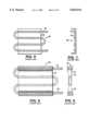
- FIGS. 3-5Another type of conventional liquid cooled heat sink is shown in FIGS. 3-5.
- This copper heat sink 40includes a set of machine drilled conduits 44, 46, 48 which act together to form the passageway for the liquid coolant.
- Conduit 46forms the connecting channel at one end of the heat sink and runs perpendicular or transverse to the conduits 44, 48.
- Conduit 46contains a plug 50 to prevent liquid from emptying out.
- copper adapter pipes 52are inserted and soldered, or brazed, in place.
- U-shaped connector pipes 54an also be used to connect adjacent conduits.
- the liquid cooled heat sink 40includes mounting holes 58 disposed in flange sections 56.
- FIGS. 6 and 7disclose another conventional liquid cooled heat sink 60.
- the aluminum block 62has been extruded and the copper tubing 64 is disposed on the back side of the heat sink.
- FIGS. 8 and 9illustrate yet another version of a liquid cooled heat sink 70.
- the copper tube 74is sandwiched between two aluminum blocks 72.
- the fluid passagesare made from a singular piece of copper tubing that has been bent into a multiple of parallel cooling passages.
- the aluminum body(for mounting of the heat generating devices) is extruded to minimize fabrication costs.
- FIGS. 6 and 7illustrate a cold plate 60 that is made from one piece of aluminum 62 with grooves to hold the tubing 64.
- FIGS. 8 and 9show a cold plate 70 that consists of two pieces of aluminum 72 with the tubing 74 "sandwiched" between them.
- a heat conducting compoundsuch as thermal grease or adhesive is used to eliminate the air gaps between the extruded body and the tubing. While these designs are less expensive to construct, they are also less effective in the removal of heat energy. They are made with aluminum, a less conductive material than copper and they introduce an additional interface to the flow of the heat. The thermal compound is necessary to fill the gap between the tube and the body.
- the present inventionrelates to a liquid cooled heat sink that efficiently transfers the heat energy from the heat generating components.
- the heat sinkincludes channels, or grooves, that are formed in at least one surface of the base member.
- the channelscontain the fluid conduits that have been constrained by the channels.
- the fluid filled conduitshave a planar surface which is substantially coplanar with the surface of the heat sink which is in contact with the heat generating component. It is this structure that substantially improves the heat sink's effectiveness in removing heat energy.
- the much larger thicknesses as well as the gap filling thermal compound of the prior arthave been eliminated in all sections where the conduit contacts the heat generating component.
- the elimination of these "losses", in the thermal paththus results in an improvement in the liquid cooled heat sink's performance.
- the gain in performanceis accomplished without incurring additional costs in manufacturing the preferred embodiment.
- a liquid cooled heat sink for cooling electronic componentscomprising a heat sink base member having channels formed in at least one surface thereof and a fluid conduit disposed in the channels.
- the fluid conduithas a flattened surface which is substantially coplanar with the surface of the heat sink base member having the channels therein.
- a method of manufacturing a liquid cooled heat sinkcomprising the steps of providing a heat sink base member having channels formed in at least one surface of the heat sink base member; providing a thermally conductive adhesive in the channels; inserting a fluid conduit into the channels; and pressing the fluid conduit into the channels so as to deform the fluid conduit into a shape where one surface of the fluid conduit is substantially coplanar with the surface of the heat sink base member which has the channels formed therein.
- FIG. 1is a top view showing a conventional liquid cooled heat sink and mounting structure.
- FIG. 2is a side view of the conventional liquid cooled heat sink of FIG. 1.
- FIG. 3is a top view of another conventional liquid cooled heat sink and mounting structure.
- FIG. 4is a side view of the liquid cooled heat sink of FIG. 3.
- FIG. 5is an end view of the liquid cooled heat sink according to FIG. 3.
- FIG. 6is a top view of yet another conventional liquid cooled heat sink.
- FIG. 7is an end view of the conventional liquid cooled heat sink of FIG. 6.
- FIG. 8is a top view of still another conventional liquid cooled heat sink.
- FIG. 9is an end view of the liquid cooled heat sink of FIG. 8.
- FIG. 10is a cross sectional view of a conventional liquid cooled heat sink having an electronic component mounted thereon.
- FIG. 11is a cross sectional view of a liquid cooled heat sink having an electronic component mounted thereon according to a first embodiment of the present invention.
- FIG. 11Ais an exploded, cross sectional view of one of the channels formed in the heat sink of FIG. 11 and a conduit adapted for insertion into the channel.
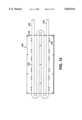
- FIG. 12is a top view of a liquid cooled heat sink according a second embodiment of the present invention.
- FIG. 13is a top view of a liquid cooled heat sink according to a third embodiment of the present invention.
- FIG. 14is a cross sectional view of the liquid cooled heat sink taken along line XIV--XIV in FIG. 13.
- FIG. 15is a side view of the liquid cooled heat sink according to the third embodiment of the present invention.
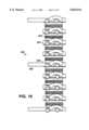
- FIG. 16is a side view of a series of electronic components which are disposed on either surface of liquid cooled heat sinks of FIG. 15, to form a stacked assembly according to the present invention.
- FIG. 17is a top view of a fluid conduit disposed in a channel which is locally deformed by a turbulating structure.
- FIG. 18is a cross sectional view taken along line XVIII--XVIII of FIG. 17 showing the fluid conduit deformation.
- FIG. 19is another embodiment of a fluid conduit which is locally deformed according to the present invention.
- FIG. 20is a cross sectional view taken along line XX--XX in FIG. 19.
- FIG. 21is a cross sectional view taken along line XXI--XXI of FIG. 19.
- FIG. 11illustrates a liquid cooled heat sink 100 according to a first embodiment of the invention.
- the liquid cooled heat sinkincludes an aluminum base member 102 which includes substantially U-shaped channels 104, 106 disposed in one side of the aluminum base member 102.
- the channels 104, 106have a substantially semi-circular bottom portion 103.
- the bottom portions 103are made up of two laterally spaced 90 degree arcs, each of radius R, as shown in FIG. 11A for channel 104.
- the channels 104, 106have upper side walls 105 which taper towards each other as they project toward the open end 107 of the channels 104, 106.
- the height, H, of the channels 104, 106is preferably about 80 percent of the outer diameter, D, of the copper tubes 114, 116.
- the bottom portion 103 of the channel 104may be entirely semi-circular and in such case the radius, R', of such bottom portion should be about 2.5 percent greater than the diameter, D; i.e., 2R' should be about 5 percent greater than D.
- Copper tubes 114, 116are disposed in the channels 104, 106. More particularly, the copper tubes 114, 116 are rolled and pressed into the channels 104, 106 so that they have upper surfaces which are flat and substantially coplanar with the upper surface of the aluminum base member 102, as shown in FIG. 11.
- the narrower sides at the upper end, 107 or mouth of the channel 104, 106will pinch the sides of the tubes 114, 116 to firmly grasp and retain the tubes 114, 116 within the channels 102, 104.
- the copper tubes 114, 116are attached to the aluminum base member 102 by an adhesive 108 which covers the curved surface of the tubes and provides good thermal conductivity between the base member 102 and the tubes 114, 116.
- the adhesive 108can be an epoxy, a thermally conductive silicone rubber or any other type of adhesive which will provide good thermal conductivity between the tubes 114, 116 and the aluminum base member 102.
- the adhesivebe supplied in a large enough quantity to completely cover the curved surface of the tube and remove any air gaps between the tubes 114, 116 and the base member 102. It is noted that the pinching action resulting from the narrower span across the mouth of the channel, together with the adhesive, provides the requisite forces necessary to retain the tubes within the channels in the presence of the heat transferred through the tubes and the base member 102.
- the tubes 114, 116include a flat surface 110 which is substantially coplanar with the upper surface 118 of the aluminum base member 102.
- the flat surface of the heat sink 100provides for good thermal conductivity between the electronic component 112 and the liquid cooled heat sink 100. With this structure, heat transfer is allowed to pass directly into the fluid conduits without passing through other components.
- FIG. 12illustrates a further embodiment of the present invention.
- a liquid cooled heat sink 120is shown.
- the heat sink 120includes an aluminum block member 122 having a copper tube 124 disposed in channels formed in a surface of the aluminum block 122.
- the copper tubeincludes an inlet and outlet 126, 128.
- Mounting holes 130are also provided for mounting electronic components across the four passes of the copper tube 124 disposed in the aluminum block 122.
- FIGS. 13-15illustrate a further embodiment of the present invention.
- a liquid cooled heat sink 150is provided.
- the heat sink 150comprises an aluminum block 152 having a copper tube disposed therein.
- the copper tubeincludes various straight sections 154, 156, 158 and 160 which are disposed in channels formed in a surface of the aluminum block 152. These sections are joined by connecting portions 162, 164 and 166.
- the aluminum block or base member 152includes channels which are formed in opposite sides of the heat sink. This allows for electronic components to be mounted on either side of the heat sink 150.
- the arrangement of the copper tubeis such that section 154 is disposed below the aluminum block 152 as seen in FIG. 13.
- the U-shaped bend section 162is then disposed at an angle so as to allow the next section of the tube 156 to be disposed in the upper surface of the heat sink 152.
- U-bend 164is also disposed at an angle so that it connects section 156 with tube section 158 which is disposed below the heat sink as seen in FIG. 13.
- U-bend section 166is also disposed at an angle to connect tube section 158 with tube section 160.
- Tube section 160is disposed below the heat sink block 152.
- FIG. 16illustrates a stacked arrangement of electronic components which are spaced apart by liquid cooled heat sinks such as that shown in FIGS. 13-15.
- the stacked arrangement 200includes heat sinks 202 that are disposed adjacent to the electronic component 204.
- Some heat sinks such as heat sink 206include extensions 208 for various electrical connections (not shown).
- the fluid's convective heat transfer rateis determined by its absorptive characteristics and the fluid passage geometry.
- a relatively smooth, unchanging uniform interior surfacesuch as a machined groove or tube will result in minimal disturbance of the fluid's flow.
- a very rough surface, changes in fluid direction or passage cross sectionwill induce disturbances in the fluid flow. Whenever a disturbance occurs, it will locally improve the fluid's heat transfer rate while slightly increasing the pressure losses. If there is no subsequent changes in the passage geometry, the disturbances will subside and the fluid's heat transfer rate will return to its prior value.
- FIGS. 17 and 18illustrate such an enhanced localized heat transfer mechanism according to the present invention.
- the thermal heat fluxis generally concentrated within a few locations along the thermal interface plane.
- additional performancehas been provided by machining additional cooling passages within the part.
- additional performancewas provided by using interior finned tubing or adding flow turbulence inserts into the fluid conduit in the heat sink. All of these methods for providing enhanced localized heat transfer incurred additional costs for the heat sink and also severely impacted the fluid pressure drop through the fluid conduits.
- FIGS. 17-18illustrate one embodiment for creating a localized cross sectional area change in the fluid conduit passage by selectively contouring the aluminum base member channel.
- an aluminum block section 240is provided with a tube 246.
- the normal width of the tubeis shown at the portion illustrated by reference numeral 242.
- the expanded width section, shown at 244,is what results after the fluid conduit has been inserted and pressed into the channel. It is noted that the width change at 244 has been exaggerated for purposes of illustration.
- the enlarged widthis caused when the round copper tube 246 is inserted into the channel and contacts a ridge 248 which extends transverse to the direction of the fluid conduit 246. This ridge 248 causes a local deformation of the tube 246 as shown in the region 250.
- the main feature of this designis that the enhanced performance is selectively located and consequently the liquid cooled heat sink's overall pressure drop is minimized.
- FIGS. 19 and 20illustrate another embodiment of the localized heat transfer improvement.
- FIG. 19illustrates an aluminum block 260 having a copper tube 262 disposed therein.
- the block member 260includes a bump or protrusion 264 in the surface of the channel. This causes a matching, localized bump 266 in the surface of tube 262.
- FIG. 21illustrates a cross section of FIG. 19 and shows the local deformation 266 caused by the protrusion 264.
- the method for forming the high contact heat sinkis as follows. First, an aluminum block is cast or extruded in the desired shape so that it includes grooves for receiving the copper tubes therein.
- An alternative to casting or extruding the aluminum blockwould be to use a solid aluminum block and machine the channels that would receive the copper tubes as well as possibly even machining the final block shape.
- the adhesive materialcan be an epoxy, a thermally conductive silicon rubber or any other type of adhesive which will provide a good thermal interface.
- a round cross section copper tubeis then inserted into the channels.
- a flat punch or pressis then used to flatten one side of the tube while simultaneously forcing the remaining portion of the copper tube into contact with the adhesive and the channel walls. The object during this procedure is to eliminate all air gaps between the copper tube and the aluminum block to thereby provide a good conduction path for heat transfer.
- the flat punch or pressis removed following the tube compression step, there may be some spring back of the flattened tube wall or other irregularities which have been formed in the tube wall surface, such as crinkling of the tube surface.
- a further processing stepmay be required.
- the surface of the aluminum block and the surface of the flattened tubemay be machined flat to provide a smooth coplanar surface. This surface will enhance thermal conductivity and thus improve the heat transfer from the heat generating component to the heat sink.
- the heat sinkcan be mounted in a known manner.
- One type of mountingincludes attaching the electronic component to the heat sink by screws.
- One such alternative embodimentincludes starting with a pre-shaped tube such as a D-shaped (in cross-section) tube and then casting the aluminum block around the D-shaped tube which has been preformed or bent into the desired channel shape. The cast block is then machined down to expose the flat surface of the tube so that it is coplanar with the surface of the aluminum block.
- a pre-shaped tubesuch as a D-shaped (in cross-section) tube
Landscapes
- Engineering & Computer Science (AREA)
- Physics & Mathematics (AREA)
- Power Engineering (AREA)
- Microelectronics & Electronic Packaging (AREA)
- General Physics & Mathematics (AREA)
- Computer Hardware Design (AREA)
- Condensed Matter Physics & Semiconductors (AREA)
- Thermal Sciences (AREA)
- Mechanical Engineering (AREA)
- General Engineering & Computer Science (AREA)
- Geometry (AREA)
- Cooling Or The Like Of Semiconductors Or Solid State Devices (AREA)
- Cooling Or The Like Of Electrical Apparatus (AREA)
- Fixed Capacitors And Capacitor Manufacturing Machines (AREA)
Abstract
Description
Q=kAΔT/l
Q=hAΔT
Q=EAΔT
Claims (9)
Priority Applications (12)
| Application Number | Priority Date | Filing Date | Title |
|---|---|---|---|
| US08/547,196US5829516A (en) | 1993-12-15 | 1995-10-24 | Liquid cooled heat sink for cooling electronic components |
| ES96936884TES2129382T1 (en) | 1995-10-24 | 1996-10-23 | THERMAL HEATSINK BY COOLED LIQUID TO REFRIGERATE ELECTRONIC PARTS. |
| DE69626662TDE69626662T2 (en) | 1995-10-24 | 1996-10-23 | LIQUID-COOLED HEAT SINK FOR COOLING ELECTRONIC COMPONENTS |
| AU74696/96AAU700624B2 (en) | 1995-10-24 | 1996-10-23 | Liquid cooled heat sink for cooling electronic components |
| JP51674497AJP3199384B2 (en) | 1995-10-24 | 1996-10-23 | Liquid-cooled heat sink for cooling electronic components and method of forming the same |
| AT96936884TATE234452T1 (en) | 1995-10-24 | 1996-10-23 | LIQUID-COOLED HEAT SINK FOR COOLING ELECTRONIC COMPONENTS |
| EP96936884AEP0858578B1 (en) | 1995-10-24 | 1996-10-23 | Liquid cooled heat sink for cooling electronic components |
| CA002235620ACA2235620A1 (en) | 1995-10-24 | 1996-10-23 | Liquid cooled heat sink for cooling electronic components |
| KR1019980702977AKR19990067040A (en) | 1995-10-24 | 1996-10-23 | Fluid Cooling Radiator for Electronic Device Cooling |
| PCT/US1996/016990WO1997015801A1 (en) | 1995-10-24 | 1996-10-23 | Liquid cooled heat sink for cooling electronic components |
| DE0858578TDE858578T1 (en) | 1995-10-24 | 1996-10-23 | LIQUID-COOLED HEAT SINK FOR COOLING ELECTRONIC COMPONENTS |
| NO981876ANO981876L (en) | 1995-10-24 | 1998-04-24 | Liquid cooling of electronic components |
Applications Claiming Priority (2)
| Application Number | Priority Date | Filing Date | Title |
|---|---|---|---|
| US16687193A | 1993-12-15 | 1993-12-15 | |
| US08/547,196US5829516A (en) | 1993-12-15 | 1995-10-24 | Liquid cooled heat sink for cooling electronic components |
Related Parent Applications (1)
| Application Number | Title | Priority Date | Filing Date |
|---|---|---|---|
| US16687193AContinuation-In-Part | 1993-12-15 | 1993-12-15 |
Publications (1)
| Publication Number | Publication Date |
|---|---|
| US5829516Atrue US5829516A (en) | 1998-11-03 |
Family
ID=24183713
Family Applications (1)
| Application Number | Title | Priority Date | Filing Date |
|---|---|---|---|
| US08/547,196Expired - LifetimeUS5829516A (en) | 1993-12-15 | 1995-10-24 | Liquid cooled heat sink for cooling electronic components |
Country Status (11)
| Country | Link |
|---|---|
| US (1) | US5829516A (en) |
| EP (1) | EP0858578B1 (en) |
| JP (1) | JP3199384B2 (en) |
| KR (1) | KR19990067040A (en) |
| AT (1) | ATE234452T1 (en) |
| AU (1) | AU700624B2 (en) |
| CA (1) | CA2235620A1 (en) |
| DE (2) | DE69626662T2 (en) |
| ES (1) | ES2129382T1 (en) |
| NO (1) | NO981876L (en) |
| WO (1) | WO1997015801A1 (en) |
Cited By (94)
| Publication number | Priority date | Publication date | Assignee | Title |
|---|---|---|---|---|
| US6053238A (en)* | 1998-10-30 | 2000-04-25 | International Business Machines Corporation | Center feed parallel flow cold plate for dual refrigeration systems |
| US6173759B1 (en)* | 1996-06-07 | 2001-01-16 | International Business Machines Corporation | Method of cooling electronic devices using a tube in plate heat sink |
| WO2001084068A1 (en)* | 2000-05-04 | 2001-11-08 | Aavid Thermalloy, Llc | Channel connection for pipe to block joints |
| US6344686B1 (en)* | 1998-11-27 | 2002-02-05 | Alstom Holdings | Power electronic component including cooling means |
| US6351381B1 (en) | 2001-06-20 | 2002-02-26 | Thermal Corp. | Heat management system |
| US6367543B1 (en) | 2000-12-11 | 2002-04-09 | Thermal Corp. | Liquid-cooled heat sink with thermal jacket |
| US6388882B1 (en) | 2001-07-19 | 2002-05-14 | Thermal Corp. | Integrated thermal architecture for thermal management of high power electronics |
| US20020124961A1 (en)* | 2001-02-28 | 2002-09-12 | Porter George K. | Manifolded fluid delivery system |
| US20020135961A1 (en)* | 2001-03-26 | 2002-09-26 | Chi Chang | Efficient cooler |
| US6503750B1 (en)* | 1998-11-25 | 2003-01-07 | The Regents Of The University Of California | PCR thermocycler |
| US20030010485A1 (en)* | 2001-07-13 | 2003-01-16 | Lytron, Inc. | Flattened tube cold plate for liquid cooling electrical components |
| US20030098588A1 (en)* | 2001-11-26 | 2003-05-29 | Kazuaki Yazawa | Method and apparatus for converting dissipated heat to work energy |
| US6578626B1 (en) | 2000-11-21 | 2003-06-17 | Thermal Corp. | Liquid cooled heat exchanger with enhanced flow |
| US6591898B1 (en)* | 2002-06-20 | 2003-07-15 | International Business Machines Corporation | Integrated heat sink system for a closed electronics container |
| US20030223173A1 (en)* | 2002-04-11 | 2003-12-04 | Lytron, Inc. | Tube-in-plate cooling or heating plate |
| US20030230399A1 (en)* | 2002-06-14 | 2003-12-18 | Hurlbert Kathryn M. | Apparatus and method for extracting heat from a device |
| US20040037045A1 (en)* | 2002-08-14 | 2004-02-26 | Phillips Alfred L. | Thermal bus for electronics systems |
| US6711017B2 (en)* | 2001-07-17 | 2004-03-23 | Hitachi Kokusai Electric Inc. | Cooling apparatus for electronic unit |
| US6725682B2 (en) | 2001-07-13 | 2004-04-27 | Coolit Systems Inc. | Computer cooling apparatus |
| US6729383B1 (en) | 1999-12-16 | 2004-05-04 | The United States Of America As Represented By The Secretary Of The Navy | Fluid-cooled heat sink with turbulence-enhancing support pins |
| US6773963B2 (en)* | 2002-01-16 | 2004-08-10 | Intel Corporation | Apparatus and method for containing excess thermal interface material |
| US20040184237A1 (en)* | 2003-03-05 | 2004-09-23 | Shyy-Woei Chang | Heat dissipation device with liquid coolant |
| WO2004085209A1 (en)* | 2003-03-26 | 2004-10-07 | Trw Limited | A vehicle electronic control unit |
| US20040208030A1 (en)* | 2002-01-24 | 2004-10-21 | Bhate Suresh K. | High power density inverter and components thereof |
| US6808013B2 (en)* | 2002-03-13 | 2004-10-26 | Hon Hai Precision Ind. Co., Ltd. | Heat dissipation device with working liquid received in circulatory route |
| US20050007730A1 (en)* | 2001-11-12 | 2005-01-13 | Shigeo Ohashi | Electronic apparatus |
| US20050024831A1 (en)* | 2003-07-28 | 2005-02-03 | Phillips Alfred L. | Flexible loop thermosyphon |
| US20050039880A1 (en)* | 2001-12-26 | 2005-02-24 | Scott Alexander Robin Walter | Computer cooling apparatus |
| US20050081532A1 (en)* | 2001-07-13 | 2005-04-21 | Scott Alexander R.W. | Computer cooling apparatus |
| US20050217823A1 (en)* | 2004-03-31 | 2005-10-06 | Dowa Mining Co., Ltd. | Aluminum bonding member and method for producing same |
| US20050224217A1 (en)* | 2004-04-09 | 2005-10-13 | Aavid Thermalloy, Llc | Multiple evaporator heat pipe assisted heat sink |
| US7017651B1 (en)* | 2000-09-13 | 2006-03-28 | Raytheon Company | Method and apparatus for temperature gradient control in an electronic system |
| US7017655B2 (en) | 2003-12-18 | 2006-03-28 | Modine Manufacturing Co. | Forced fluid heat sink |
| DE202005005452U1 (en)* | 2005-04-06 | 2006-08-17 | Getriebebau Nord Gmbh & Co. Kg | Gear cooler e.g. for cooling gear, has housing wall having exterior surface and inner surface with cooling agent line provided, being in connection with only exterior surface of housing wall |
| US20060198150A1 (en)* | 2005-03-01 | 2006-09-07 | Seiko Epson Corporation | Cooling unit manufacturing method, cooling unit, optical device and projector |
| US20060196050A1 (en)* | 2005-03-01 | 2006-09-07 | Seiko Epson Corporation | Manufacturing method for cooling unit, cooling unit, optical device, and projector |
| US20060243427A1 (en)* | 2005-04-28 | 2006-11-02 | Hitachi Cable, Ltd. | Heat pipe heat sink and method for fabricating the same |
| DE102005036299A1 (en)* | 2005-08-02 | 2007-02-15 | Siemens Ag | Cooling system for electronics housing |
| US20070261819A1 (en)* | 2005-12-09 | 2007-11-15 | Hon Hai Precision Industry Co., Ltd. | Heat dissipating device |
| US20080060791A1 (en)* | 2006-09-08 | 2008-03-13 | Kurt Richard Strobel | Cooling Apparatus for Electronics |
| US20080110607A1 (en)* | 2006-11-09 | 2008-05-15 | Chih-Hung Cheng | Combined assembly of fixing base and heat pipe |
| US20080174960A1 (en)* | 2007-01-22 | 2008-07-24 | Themis Computer | Clamshell enclosure for electronic circuit assemblies |
| US20080218970A1 (en)* | 2002-08-30 | 2008-09-11 | Themis Computer | Thermal Management for a Ruggedized Electronics Enclosure |
| US20090126192A1 (en)* | 2002-06-14 | 2009-05-21 | Todd John J | Heat pipe fin stack with extruded base |
| US20090154105A1 (en)* | 2007-12-18 | 2009-06-18 | Hon Hai Precision Industry Co., Ltd. | Heat dissipation device and a method for manufacturing the same |
| US20090188657A1 (en)* | 2007-07-25 | 2009-07-30 | Chi-Hun Cheng | Combined assembly of fixing base and heat pipe |
| DE102006033226B4 (en)* | 2005-10-25 | 2009-08-13 | Verigy (Singapore) Pte. Ltd. | Cooling arrangement for cooling an electrical and electronic circuit structure |
| US20090218076A1 (en)* | 2006-01-25 | 2009-09-03 | Thales | Method of manufacturing panels having integrated heat pipes and/or inserts maintained by tongues |
| US20090260782A1 (en)* | 2008-04-17 | 2009-10-22 | Aavid Thermalloy, Llc | Heat sink base plate with heat pipe |
| US20090277616A1 (en)* | 2008-05-06 | 2009-11-12 | International Business Machines Corporation | Method and apparatus of water cooling several parallel circuit cards each containing several chip packages |
| US20100025010A1 (en)* | 2008-08-04 | 2010-02-04 | International Business Machines Corporation | Apparatus and method of direct water cooling several parallel circuit cards each containing several chip packages |
| DE102008052145A1 (en)* | 2008-10-20 | 2010-04-22 | Sew-Eurodrive Gmbh & Co. Kg | Cooling arrangement for cooling agent and electric device, has heat producing component, particularly electrical or electronic construction unit or module that is cooled |
| US20100096111A1 (en)* | 2008-10-20 | 2010-04-22 | Kucherov Yan R | Heat dissipation system with boundary layer disruption |
| US20100129140A1 (en)* | 2008-11-26 | 2010-05-27 | Coolit Systems Inc. | Connector for a liquid cooling system in a computer |
| US20100188811A1 (en)* | 2007-07-05 | 2010-07-29 | Aeon Lighting Technology Inc. | Memory cooling device |
| US20100254089A1 (en)* | 2008-05-06 | 2010-10-07 | International Business Machines Corporation | Cooling System for Electronic Components |
| US20100319880A1 (en)* | 2009-06-23 | 2010-12-23 | Fu Zhun Precision Industry (Shen Zhen) Co., Ltd. | Heat dissipation device and manufacturing method thereof |
| US20100328892A1 (en)* | 2009-06-25 | 2010-12-30 | Sun Microsystems, Inc. | Molded heat sink and method of making same |
| US20110000645A1 (en)* | 2009-07-06 | 2011-01-06 | Ping Chen | Heat dissipating board structure and method of manufacturing the same |
| US7991515B2 (en) | 2007-01-15 | 2011-08-02 | Coolit Systems Inc. | Computer cooling system with preferential cooling device selection |
| US20110203773A1 (en)* | 2008-11-04 | 2011-08-25 | Daikin Industries, Ltd. | Cooling member, manufacturing method and apparatus thereof |
| US20110290450A1 (en)* | 2010-05-31 | 2011-12-01 | Asia Vital Components Co., Ltd. | Heat Dissipation Module |
| JP2012013263A (en)* | 2010-06-29 | 2012-01-19 | Kiko Kagi Kofun Yugenkoshi | Heat dissipation device and method of manufacturing the same |
| US20120043057A1 (en)* | 2010-08-19 | 2012-02-23 | Chun-Ming Wu | Heat-dissipating module |
| US20120138281A1 (en)* | 2010-12-06 | 2012-06-07 | Transistor Devices, Inc. D/B/A Tdi Power | Heat Exchanger for Electronic Assemblies |
| US20120205084A1 (en)* | 2011-02-11 | 2012-08-16 | Tsung-Hsien Huang | Heat sink module |
| US20120241132A1 (en)* | 2011-03-22 | 2012-09-27 | Tsung-Hsien Huang | Non-base block heat sink |
| US20120279686A1 (en)* | 2011-05-06 | 2012-11-08 | International Business Machines Corporation | Cooled electronic system with liquid-cooled cold plate and thermal spreader coupled to electronic component |
| US20120305221A1 (en)* | 2011-06-02 | 2012-12-06 | Tsung-Hsien Huang | Heat pipe-attached heat sink |
| US20140217870A1 (en)* | 2013-02-01 | 2014-08-07 | Emerson Network Power - Embedded Computing, Inc. | Method and device to provide uniform cooling in rugged environments |
| US20150104322A1 (en)* | 2013-10-15 | 2015-04-16 | General Electric Company | Thermal management article and method of forming the same, and method of thermal management of a substrate |
| US9132519B2 (en) | 2011-10-28 | 2015-09-15 | Interntional Business Machines Corporation | Directly connected heat exchanger tube section and coolant-cooled structure |
| WO2015166320A1 (en)* | 2014-04-30 | 2015-11-05 | Istituto Nazionale Di Fisica Nucleare | Method for producing a heat exchanger and relevant heat exchanger |
| US9185830B2 (en) | 2011-05-06 | 2015-11-10 | International Business Machines Corporation | Thermoelectric-enhanced, liquid-based cooling of a multi-component electronic system |
| USD749713S1 (en) | 2014-07-31 | 2016-02-16 | Innovative Medical Equipment, Llc | Heat exchanger |
| US9295185B2 (en) | 2013-03-13 | 2016-03-22 | Transistor Devices, Inc. | Sealed enclosure for power electronics incorporating a heat exchanger |
| US20160105998A1 (en)* | 2013-06-28 | 2016-04-14 | Trumpf Huettinger Gmbh + Co. Kg | Electronic Component Cooling |
| US20160115691A1 (en)* | 2013-05-29 | 2016-04-28 | Fujian Lopo Terracotta Panels Manufacturing Co., Ltd. | Recycling constant-temperature ceramic floor integrated system |
| US20160151178A1 (en)* | 2013-05-17 | 2016-06-02 | G. Rau Gmbh & Co. Kg | Method and device for remelting and/or remelt-alloying metallic materials, in particular nitinol |
| US9516794B2 (en) | 2014-10-31 | 2016-12-06 | Transistor Devices, Inc. | Modular scalable liquid cooled power system |
| RU2616699C2 (en)* | 2015-06-03 | 2017-04-18 | Государственное научное учреждение "Институт порошковой металлургии" | Method of heat pipe mounting to the heat receipt base |
| WO2017076442A1 (en) | 2015-11-04 | 2017-05-11 | Kongsberg Automotive Ab | An automotive power electronics assembly |
| US20180062347A1 (en)* | 2016-08-31 | 2018-03-01 | Nlight, Inc. | Laser cooling system |
| US20180058777A1 (en)* | 2016-08-26 | 2018-03-01 | Intel Corporation | Heat exchanger puck |
| US20180078997A1 (en)* | 2015-04-13 | 2018-03-22 | Hitachi Kokusai Electric Inc. | Liquid-cooling cold plate and method for manufacturing same |
| US20180168069A1 (en)* | 2016-12-09 | 2018-06-14 | Cooler Master Technology Inc. | Parallel heat-pipes type heat sink and manufacturing method thereof |
| US10168749B2 (en) | 2016-12-01 | 2019-01-01 | Intel Corporation | Cooling using adjustable thermal coupling |
| US10209003B2 (en) | 2012-02-21 | 2019-02-19 | Thermal Corp. | Electronics cabinet and rack cooling system and method |
| US10784645B2 (en) | 2018-03-12 | 2020-09-22 | Nlight, Inc. | Fiber laser having variably wound optical fiber |
| US20200373223A1 (en)* | 2019-05-23 | 2020-11-26 | Ovh | Water block assembly |
| US10962009B2 (en) | 2007-10-08 | 2021-03-30 | Emerson Climate Technologies, Inc. | Variable speed compressor protection system and method |
| US11206743B2 (en) | 2019-07-25 | 2021-12-21 | Emerson Climate Technolgies, Inc. | Electronics enclosure with heat-transfer element |
| US20220236012A1 (en)* | 2017-08-03 | 2022-07-28 | Mitsubishi Electric Corporation | Heat exchanger and refrigeration cycle apparatus |
| US20230292464A1 (en)* | 2021-11-02 | 2023-09-14 | Carrier Corporation | Mechanically expanded microfin tube liquid cooled heat sink |
Families Citing this family (19)
| Publication number | Priority date | Publication date | Assignee | Title |
|---|---|---|---|---|
| JP3082738B2 (en)* | 1998-03-13 | 2000-08-28 | 日本電気株式会社 | High efficiency liquid cooling device |
| DE10022972A1 (en)* | 2000-05-11 | 2001-11-22 | Bosch Gmbh Robert | Micro heat exchanger has a number of parallel metal hollow fiber tubes shrouded by a graphite matrix body for a high heat exchange in a simple unit |
| DE10296928T5 (en) | 2001-06-12 | 2004-10-07 | Liebert Corp | Single or double bus heat transfer system |
| JP4323116B2 (en)* | 2001-07-12 | 2009-09-02 | 株式会社明電舎 | heatsink |
| DE10319526A1 (en)* | 2003-04-30 | 2004-07-29 | OCé PRINTING SYSTEMS GMBH | Cooling device for character generator in electrophotographic printer or copier, has cooling tube plastically deformed to be in close thermal contact with heat collector. |
| DE102005016115B4 (en)* | 2005-04-08 | 2007-12-20 | Rittal Gmbh & Co. Kg | Arrangement for cooling an electronic device |
| DE102005032814A1 (en)* | 2005-07-12 | 2007-01-18 | Behr Gmbh & Co. Kg | Cooling device, in particular for an electronic control unit |
| DE102005048100B4 (en)* | 2005-09-30 | 2018-07-05 | Robert Bosch Gmbh | Electrical device, in particular electronic control device for motor vehicles |
| DE102005048492B4 (en)* | 2005-10-07 | 2009-06-04 | Curamik Electronics Gmbh | Electric module |
| ITBS20070013U1 (en)* | 2007-03-02 | 2008-09-03 | Federico Guastaroba | FORCED DUCTING LOCKING SYSTEM FOR THERMAL EXCHANGER |
| DE102007015859B4 (en)* | 2007-04-02 | 2009-02-19 | Reiner Dziadek | Heat exchanger, a cooling arrangement with the heat exchanger, as well as its use and cooling method |
| DE102008050065A1 (en) | 2008-10-01 | 2010-04-08 | Reiner Dziadek | Heat exchanger for cooling electrical component and modules or systems, particularly carrier plate or printed circuit board, is integrated in electrical printed circuit board |
| JP4766283B2 (en)* | 2008-11-11 | 2011-09-07 | ダイキン工業株式会社 | Cooling member and manufacturing method thereof |
| JP4470125B1 (en)* | 2008-11-17 | 2010-06-02 | ダイキン工業株式会社 | Cooling member, manufacturing method thereof, and manufacturing apparatus |
| JP5724709B2 (en)* | 2011-07-20 | 2015-05-27 | ダイキン工業株式会社 | Refrigerant cooling mechanism and cooling unit |
| JP6374739B2 (en)* | 2014-09-19 | 2018-08-15 | 株式会社沖データ | Exposure apparatus and image forming apparatus |
| JP2017228105A (en)* | 2016-06-23 | 2017-12-28 | 富士通株式会社 | Information processor |
| US10279610B2 (en)* | 2016-12-20 | 2019-05-07 | Xerox Corporation | Cooling insert |
| US10644474B2 (en)* | 2018-03-07 | 2020-05-05 | Coherent, Inc. | Conductively-cooled slab laser |
Citations (25)
| Publication number | Priority date | Publication date | Assignee | Title |
|---|---|---|---|---|
| US2522365A (en)* | 1949-01-07 | 1950-09-12 | Edward S Greene | Extrusion machine cylinder |
| GB758524A (en)* | 1952-08-27 | 1956-10-03 | Siemens Ag | Improvements in or relating to dry-rectifiers with liquid cooling arrangements |
| GB826625A (en)* | 1956-12-04 | 1960-01-13 | Porter & Co Salford Ltd T | Improvements relating to heat exchange apparatus |
| US3275921A (en)* | 1963-04-03 | 1966-09-27 | Westinghouse Electric Corp | Semiconductor rectifier assembly |
| US3643131A (en)* | 1969-05-10 | 1972-02-15 | Siemens Ag | Electrical device having liquid-cooled clamped disc cells |
| US4185369A (en)* | 1978-03-22 | 1980-01-29 | General Electric Company | Method of manufacture of cooled turbine or compressor buckets |
| US4187711A (en)* | 1977-04-25 | 1980-02-12 | Wakefield Engineering, Inc. | Method and apparatus for producing a high fin density extruded heat dissipator |
| JPS56137035A (en)* | 1980-03-28 | 1981-10-26 | Nippon Alum Mfg Co Ltd:The | Heat exchanger unit and manufacture thereof |
| GB2079655A (en)* | 1980-07-07 | 1982-01-27 | Connell John O | Heat exchanger panel |
| US4378626A (en)* | 1981-06-10 | 1983-04-05 | United Technologies Corporation | Cooled mirror construction by chemical vapor deposition |
| US4508163A (en)* | 1983-01-18 | 1985-04-02 | Aavid Engineering, Inc. | Heat sinks for integrated circuit modules |
| US4509839A (en)* | 1983-06-16 | 1985-04-09 | Imc Magnetics Corp. | Heat dissipator for semiconductor devices |
| US4544942A (en)* | 1982-02-22 | 1985-10-01 | Aavid Engineering, Inc. | Heat sinks with staked solderable studs |
| EP0157370A2 (en)* | 1984-04-03 | 1985-10-09 | Norsk Hydro A/S | Heat exchanger panel and method of maufacture |
| JPS6151861A (en)* | 1984-08-22 | 1986-03-14 | Hitachi Ltd | Package for semiconductor element |
| JPS63221655A (en)* | 1987-03-10 | 1988-09-14 | Fujitsu Ltd | Element cooling method |
| JPS63262861A (en)* | 1987-04-21 | 1988-10-31 | Toshiba Corp | Cooling body for semiconductor devices |
| JPH01286349A (en)* | 1988-05-12 | 1989-11-17 | Nec Corp | Cooling device of integrated circuit |
| JPH0240951A (en)* | 1988-07-31 | 1990-02-09 | Nec Corp | semiconductor memory device |
| US4933746A (en)* | 1988-09-12 | 1990-06-12 | Aavid Engineering, Inc. | Three-legged clip |
| CH677293A5 (en)* | 1989-01-16 | 1991-04-30 | Asea Brown Boveri | Power semiconductor heat sink - has meandering flow path containing insulating hose filled with cooling fluid |
| JPH03142026A (en)* | 1989-10-27 | 1991-06-17 | Nippon Alum Mfg Co Ltd | Pipe on sheet type heat exchanger and manufacture thereof |
| US5040096A (en)* | 1990-06-07 | 1991-08-13 | Aavid Engineering, Inc. | High force clip |
| US5154792A (en)* | 1990-12-28 | 1992-10-13 | Basf Corporation | Bonding method employing urethane adhesives having good heat transfer properties |
| US5454428A (en)* | 1993-11-22 | 1995-10-03 | Radiant Engineering, Inc. | Hydronic radiant heat distribution panel and system |
Family Cites Families (1)
| Publication number | Priority date | Publication date | Assignee | Title |
|---|---|---|---|---|
| WO1995017765A2 (en) | 1993-12-15 | 1995-06-29 | Aavid Engineering, Inc. | Liquid cooled heat sink for cooling electronic components |
- 1995
- 1995-10-24USUS08/547,196patent/US5829516A/ennot_activeExpired - Lifetime
- 1996
- 1996-10-23CACA002235620Apatent/CA2235620A1/ennot_activeAbandoned
- 1996-10-23ESES96936884Tpatent/ES2129382T1/enactivePending
- 1996-10-23JPJP51674497Apatent/JP3199384B2/ennot_activeExpired - Fee Related
- 1996-10-23EPEP96936884Apatent/EP0858578B1/ennot_activeExpired - Lifetime
- 1996-10-23ATAT96936884Tpatent/ATE234452T1/ennot_activeIP Right Cessation
- 1996-10-23WOPCT/US1996/016990patent/WO1997015801A1/enactiveIP Right Grant
- 1996-10-23KRKR1019980702977Apatent/KR19990067040A/ennot_activeAbandoned
- 1996-10-23DEDE69626662Tpatent/DE69626662T2/ennot_activeExpired - Lifetime
- 1996-10-23DEDE0858578Tpatent/DE858578T1/enactivePending
- 1996-10-23AUAU74696/96Apatent/AU700624B2/ennot_activeCeased
- 1998
- 1998-04-24NONO981876Apatent/NO981876L/ennot_activeApplication Discontinuation
Patent Citations (25)
| Publication number | Priority date | Publication date | Assignee | Title |
|---|---|---|---|---|
| US2522365A (en)* | 1949-01-07 | 1950-09-12 | Edward S Greene | Extrusion machine cylinder |
| GB758524A (en)* | 1952-08-27 | 1956-10-03 | Siemens Ag | Improvements in or relating to dry-rectifiers with liquid cooling arrangements |
| GB826625A (en)* | 1956-12-04 | 1960-01-13 | Porter & Co Salford Ltd T | Improvements relating to heat exchange apparatus |
| US3275921A (en)* | 1963-04-03 | 1966-09-27 | Westinghouse Electric Corp | Semiconductor rectifier assembly |
| US3643131A (en)* | 1969-05-10 | 1972-02-15 | Siemens Ag | Electrical device having liquid-cooled clamped disc cells |
| US4187711A (en)* | 1977-04-25 | 1980-02-12 | Wakefield Engineering, Inc. | Method and apparatus for producing a high fin density extruded heat dissipator |
| US4185369A (en)* | 1978-03-22 | 1980-01-29 | General Electric Company | Method of manufacture of cooled turbine or compressor buckets |
| JPS56137035A (en)* | 1980-03-28 | 1981-10-26 | Nippon Alum Mfg Co Ltd:The | Heat exchanger unit and manufacture thereof |
| GB2079655A (en)* | 1980-07-07 | 1982-01-27 | Connell John O | Heat exchanger panel |
| US4378626A (en)* | 1981-06-10 | 1983-04-05 | United Technologies Corporation | Cooled mirror construction by chemical vapor deposition |
| US4544942A (en)* | 1982-02-22 | 1985-10-01 | Aavid Engineering, Inc. | Heat sinks with staked solderable studs |
| US4508163A (en)* | 1983-01-18 | 1985-04-02 | Aavid Engineering, Inc. | Heat sinks for integrated circuit modules |
| US4509839A (en)* | 1983-06-16 | 1985-04-09 | Imc Magnetics Corp. | Heat dissipator for semiconductor devices |
| EP0157370A2 (en)* | 1984-04-03 | 1985-10-09 | Norsk Hydro A/S | Heat exchanger panel and method of maufacture |
| JPS6151861A (en)* | 1984-08-22 | 1986-03-14 | Hitachi Ltd | Package for semiconductor element |
| JPS63221655A (en)* | 1987-03-10 | 1988-09-14 | Fujitsu Ltd | Element cooling method |
| JPS63262861A (en)* | 1987-04-21 | 1988-10-31 | Toshiba Corp | Cooling body for semiconductor devices |
| JPH01286349A (en)* | 1988-05-12 | 1989-11-17 | Nec Corp | Cooling device of integrated circuit |
| JPH0240951A (en)* | 1988-07-31 | 1990-02-09 | Nec Corp | semiconductor memory device |
| US4933746A (en)* | 1988-09-12 | 1990-06-12 | Aavid Engineering, Inc. | Three-legged clip |
| CH677293A5 (en)* | 1989-01-16 | 1991-04-30 | Asea Brown Boveri | Power semiconductor heat sink - has meandering flow path containing insulating hose filled with cooling fluid |
| JPH03142026A (en)* | 1989-10-27 | 1991-06-17 | Nippon Alum Mfg Co Ltd | Pipe on sheet type heat exchanger and manufacture thereof |
| US5040096A (en)* | 1990-06-07 | 1991-08-13 | Aavid Engineering, Inc. | High force clip |
| US5154792A (en)* | 1990-12-28 | 1992-10-13 | Basf Corporation | Bonding method employing urethane adhesives having good heat transfer properties |
| US5454428A (en)* | 1993-11-22 | 1995-10-03 | Radiant Engineering, Inc. | Hydronic radiant heat distribution panel and system |
Cited By (164)
| Publication number | Priority date | Publication date | Assignee | Title |
|---|---|---|---|---|
| US6173759B1 (en)* | 1996-06-07 | 2001-01-16 | International Business Machines Corporation | Method of cooling electronic devices using a tube in plate heat sink |
| US6167621B1 (en) | 1998-10-30 | 2001-01-02 | International Business Machines Corporation | Center feed parallel flow cold plate dual refrigeration systems |
| US6053238A (en)* | 1998-10-30 | 2000-04-25 | International Business Machines Corporation | Center feed parallel flow cold plate for dual refrigeration systems |
| US6893863B2 (en)* | 1998-11-25 | 2005-05-17 | The Regents Of The University Of California | PCR thermocycler |
| US20030036189A1 (en)* | 1998-11-25 | 2003-02-20 | The Regents Of The University Of California | PCR thermocycler |
| US6503750B1 (en)* | 1998-11-25 | 2003-01-07 | The Regents Of The University Of California | PCR thermocycler |
| US6344686B1 (en)* | 1998-11-27 | 2002-02-05 | Alstom Holdings | Power electronic component including cooling means |
| US6729383B1 (en) | 1999-12-16 | 2004-05-04 | The United States Of America As Represented By The Secretary Of The Navy | Fluid-cooled heat sink with turbulence-enhancing support pins |
| WO2001084068A1 (en)* | 2000-05-04 | 2001-11-08 | Aavid Thermalloy, Llc | Channel connection for pipe to block joints |
| US7017651B1 (en)* | 2000-09-13 | 2006-03-28 | Raytheon Company | Method and apparatus for temperature gradient control in an electronic system |
| US6719039B2 (en) | 2000-11-21 | 2004-04-13 | Thermal Corp. | Liquid cooled heat exchanger with enhanced flow |
| US6578626B1 (en) | 2000-11-21 | 2003-06-17 | Thermal Corp. | Liquid cooled heat exchanger with enhanced flow |
| US6397932B1 (en) | 2000-12-11 | 2002-06-04 | Douglas P. Calaman | Liquid-cooled heat sink with thermal jacket |
| US6367543B1 (en) | 2000-12-11 | 2002-04-09 | Thermal Corp. | Liquid-cooled heat sink with thermal jacket |
| US20020148406A1 (en)* | 2001-02-28 | 2002-10-17 | Porter George K. | Atomizer |
| US6892762B2 (en) | 2001-02-28 | 2005-05-17 | Porter Instrument Company, Inc. | Manifolded fluid delivery system |
| US20020124961A1 (en)* | 2001-02-28 | 2002-09-12 | Porter George K. | Manifolded fluid delivery system |
| US6694809B2 (en) | 2001-02-28 | 2004-02-24 | Porter Instrument Company, Inc. | Flow controller |
| US6834848B2 (en) | 2001-02-28 | 2004-12-28 | Porter Instrument Company, Inc. | Atomizer |
| US20020135961A1 (en)* | 2001-03-26 | 2002-09-26 | Chi Chang | Efficient cooler |
| US6856510B2 (en)* | 2001-03-26 | 2005-02-15 | Chi Mei Chang | Efficient cooler |
| US6351381B1 (en) | 2001-06-20 | 2002-02-26 | Thermal Corp. | Heat management system |
| US6725682B2 (en) | 2001-07-13 | 2004-04-27 | Coolit Systems Inc. | Computer cooling apparatus |
| US7178586B2 (en) | 2001-07-13 | 2007-02-20 | Lytron, Inc. | Flattened tube cold plate for liquid cooling electrical components |
| US20080041566A1 (en)* | 2001-07-13 | 2008-02-21 | Coolit Systems Inc. | Computer Cooling Apparatus |
| US20030010485A1 (en)* | 2001-07-13 | 2003-01-16 | Lytron, Inc. | Flattened tube cold plate for liquid cooling electrical components |
| US7739883B2 (en) | 2001-07-13 | 2010-06-22 | Coolit Systems Inc. | Computer cooling apparatus |
| US20050081532A1 (en)* | 2001-07-13 | 2005-04-21 | Scott Alexander R.W. | Computer cooling apparatus |
| US7174738B2 (en) | 2001-07-13 | 2007-02-13 | Coolit Systems Inc. | Computer cooling apparatus |
| US6711017B2 (en)* | 2001-07-17 | 2004-03-23 | Hitachi Kokusai Electric Inc. | Cooling apparatus for electronic unit |
| US6388882B1 (en) | 2001-07-19 | 2002-05-14 | Thermal Corp. | Integrated thermal architecture for thermal management of high power electronics |
| US20050007730A1 (en)* | 2001-11-12 | 2005-01-13 | Shigeo Ohashi | Electronic apparatus |
| US6856037B2 (en)* | 2001-11-26 | 2005-02-15 | Sony Corporation | Method and apparatus for converting dissipated heat to work energy |
| US20030098588A1 (en)* | 2001-11-26 | 2003-05-29 | Kazuaki Yazawa | Method and apparatus for converting dissipated heat to work energy |
| US20050039880A1 (en)* | 2001-12-26 | 2005-02-24 | Scott Alexander Robin Walter | Computer cooling apparatus |
| US6773963B2 (en)* | 2002-01-16 | 2004-08-10 | Intel Corporation | Apparatus and method for containing excess thermal interface material |
| US6980450B2 (en) | 2002-01-24 | 2005-12-27 | Inverters Unlimited, Inc. | High power density inverter and components thereof |
| US20040208030A1 (en)* | 2002-01-24 | 2004-10-21 | Bhate Suresh K. | High power density inverter and components thereof |
| US6808013B2 (en)* | 2002-03-13 | 2004-10-26 | Hon Hai Precision Ind. Co., Ltd. | Heat dissipation device with working liquid received in circulatory route |
| US20030223173A1 (en)* | 2002-04-11 | 2003-12-04 | Lytron, Inc. | Tube-in-plate cooling or heating plate |
| US6853555B2 (en)* | 2002-04-11 | 2005-02-08 | Lytron, Inc. | Tube-in-plate cooling or heating plate |
| US20030230399A1 (en)* | 2002-06-14 | 2003-12-18 | Hurlbert Kathryn M. | Apparatus and method for extracting heat from a device |
| US20090126192A1 (en)* | 2002-06-14 | 2009-05-21 | Todd John J | Heat pipe fin stack with extruded base |
| US8584738B2 (en)* | 2002-06-14 | 2013-11-19 | Lockheed Martin Corporation | Apparatus and method for extracting heat from a device |
| US6591898B1 (en)* | 2002-06-20 | 2003-07-15 | International Business Machines Corporation | Integrated heat sink system for a closed electronics container |
| US20040037045A1 (en)* | 2002-08-14 | 2004-02-26 | Phillips Alfred L. | Thermal bus for electronics systems |
| US6804117B2 (en) | 2002-08-14 | 2004-10-12 | Thermal Corp. | Thermal bus for electronics systems |
| US20080218970A1 (en)* | 2002-08-30 | 2008-09-11 | Themis Computer | Thermal Management for a Ruggedized Electronics Enclosure |
| US6867973B2 (en)* | 2003-03-05 | 2005-03-15 | Shyy-Woei Chang | Heat dissipation device with liquid coolant |
| US20040184237A1 (en)* | 2003-03-05 | 2004-09-23 | Shyy-Woei Chang | Heat dissipation device with liquid coolant |
| WO2004085209A1 (en)* | 2003-03-26 | 2004-10-07 | Trw Limited | A vehicle electronic control unit |
| US7013955B2 (en) | 2003-07-28 | 2006-03-21 | Thermal Corp. | Flexible loop thermosyphon |
| US20060254753A1 (en)* | 2003-07-28 | 2006-11-16 | Phillips Alfred L | Flexible loop thermosyphon |
| US7096928B2 (en) | 2003-07-28 | 2006-08-29 | Thermal Corp. | Flexible loop thermosyphon |
| US20060000582A1 (en)* | 2003-07-28 | 2006-01-05 | Phillips Alfred L | Flexible loop thermosyphon |
| US20050024831A1 (en)* | 2003-07-28 | 2005-02-03 | Phillips Alfred L. | Flexible loop thermosyphon |
| US7017655B2 (en) | 2003-12-18 | 2006-03-28 | Modine Manufacturing Co. | Forced fluid heat sink |
| US20050217823A1 (en)* | 2004-03-31 | 2005-10-06 | Dowa Mining Co., Ltd. | Aluminum bonding member and method for producing same |
| EP1585173A3 (en)* | 2004-03-31 | 2006-10-11 | Dowa Mining Co., Ltd. | Aluminium bonding member and method for producing same |
| US8745841B2 (en)* | 2004-03-31 | 2014-06-10 | Dowa Metaltech Co., Ltd. | Aluminum bonding member and method for producing same |
| US20050224217A1 (en)* | 2004-04-09 | 2005-10-13 | Aavid Thermalloy, Llc | Multiple evaporator heat pipe assisted heat sink |
| US7059391B2 (en) | 2004-04-09 | 2006-06-13 | Aavid Thermalloy, Inc. | Multiple evaporator heat pipe assisted heat sink |
| US20060196050A1 (en)* | 2005-03-01 | 2006-09-07 | Seiko Epson Corporation | Manufacturing method for cooling unit, cooling unit, optical device, and projector |
| US7585076B2 (en)* | 2005-03-01 | 2009-09-08 | Seiko Epson Corporation | Cooling unit manufacturing method, cooling unit, optical device and projector |
| US7717568B2 (en) | 2005-03-01 | 2010-05-18 | Seiko Epson Corporation | Manufacturing method for cooling unit, cooling unit, optical device, and projector |
| US20060198150A1 (en)* | 2005-03-01 | 2006-09-07 | Seiko Epson Corporation | Cooling unit manufacturing method, cooling unit, optical device and projector |
| DE202005005452U1 (en)* | 2005-04-06 | 2006-08-17 | Getriebebau Nord Gmbh & Co. Kg | Gear cooler e.g. for cooling gear, has housing wall having exterior surface and inner surface with cooling agent line provided, being in connection with only exterior surface of housing wall |
| US20060243427A1 (en)* | 2005-04-28 | 2006-11-02 | Hitachi Cable, Ltd. | Heat pipe heat sink and method for fabricating the same |
| DE102005036299B4 (en)* | 2005-08-02 | 2008-01-24 | Siemens Ag | cooling arrangement |
| WO2007014801A3 (en)* | 2005-08-02 | 2007-07-26 | Siemens Ag | Cooling system for electronics housings |
| US20080212281A1 (en)* | 2005-08-02 | 2008-09-04 | Siemens Vdo Automotive Ag | Cooling System for Electronics Housing |
| DE102005036299A1 (en)* | 2005-08-02 | 2007-02-15 | Siemens Ag | Cooling system for electronics housing |
| US7684195B2 (en) | 2005-08-02 | 2010-03-23 | Siemens Vdo Automotive Ag | Cooling system for electronics housing |
| DE102006033226B4 (en)* | 2005-10-25 | 2009-08-13 | Verigy (Singapore) Pte. Ltd. | Cooling arrangement for cooling an electrical and electronic circuit structure |
| US20070261819A1 (en)* | 2005-12-09 | 2007-11-15 | Hon Hai Precision Industry Co., Ltd. | Heat dissipating device |
| US20090218076A1 (en)* | 2006-01-25 | 2009-09-03 | Thales | Method of manufacturing panels having integrated heat pipes and/or inserts maintained by tongues |
| US8407894B2 (en)* | 2006-01-25 | 2013-04-02 | Thales | Method of manufacturing panels having integrated heat pipes and/or inserts maintained by tongues |
| US7624791B2 (en) | 2006-09-08 | 2009-12-01 | Advanced Energy Industries, Inc. | Cooling apparatus for electronics |
| US20080060791A1 (en)* | 2006-09-08 | 2008-03-13 | Kurt Richard Strobel | Cooling Apparatus for Electronics |
| US20080110607A1 (en)* | 2006-11-09 | 2008-05-15 | Chih-Hung Cheng | Combined assembly of fixing base and heat pipe |
| US7991515B2 (en) | 2007-01-15 | 2011-08-02 | Coolit Systems Inc. | Computer cooling system with preferential cooling device selection |
| US20080174960A1 (en)* | 2007-01-22 | 2008-07-24 | Themis Computer | Clamshell enclosure for electronic circuit assemblies |
| US20100188811A1 (en)* | 2007-07-05 | 2010-07-29 | Aeon Lighting Technology Inc. | Memory cooling device |
| US20090188657A1 (en)* | 2007-07-25 | 2009-07-30 | Chi-Hun Cheng | Combined assembly of fixing base and heat pipe |
| US7950445B2 (en)* | 2007-07-25 | 2011-05-31 | Golden Sun News Techniques Co., Ltd. | Combined assembly of fixing base and heat pipe |
| US10962009B2 (en) | 2007-10-08 | 2021-03-30 | Emerson Climate Technologies, Inc. | Variable speed compressor protection system and method |
| US20090154105A1 (en)* | 2007-12-18 | 2009-06-18 | Hon Hai Precision Industry Co., Ltd. | Heat dissipation device and a method for manufacturing the same |
| US7643293B2 (en)* | 2007-12-18 | 2010-01-05 | Hon Hai Precision Industry Co., Ltd. | Heat dissipation device and a method for manufacturing the same |
| US8286693B2 (en) | 2008-04-17 | 2012-10-16 | Aavid Thermalloy, Llc | Heat sink base plate with heat pipe |
| US20090260782A1 (en)* | 2008-04-17 | 2009-10-22 | Aavid Thermalloy, Llc | Heat sink base plate with heat pipe |
| US20100254089A1 (en)* | 2008-05-06 | 2010-10-07 | International Business Machines Corporation | Cooling System for Electronic Components |
| US9213378B2 (en) | 2008-05-06 | 2015-12-15 | International Business Machines Corporation | Cooling system for electronic components |
| US9342121B2 (en) | 2008-05-06 | 2016-05-17 | International Business Machines Corporatoin | Cooling system for electronic components |
| US20090277616A1 (en)* | 2008-05-06 | 2009-11-12 | International Business Machines Corporation | Method and apparatus of water cooling several parallel circuit cards each containing several chip packages |
| US8004841B2 (en) | 2008-05-06 | 2011-08-23 | International Business Machines Corporation | Method and apparatus of water cooling several parallel circuit cards each containing several chip packages |
| US20100025010A1 (en)* | 2008-08-04 | 2010-02-04 | International Business Machines Corporation | Apparatus and method of direct water cooling several parallel circuit cards each containing several chip packages |
| US8081473B2 (en) | 2008-08-04 | 2011-12-20 | International Business Machines Corporation | Apparatus and method of direct water cooling several parallel circuit cards each containing several chip packages |
| DE102008052145A1 (en)* | 2008-10-20 | 2010-04-22 | Sew-Eurodrive Gmbh & Co. Kg | Cooling arrangement for cooling agent and electric device, has heat producing component, particularly electrical or electronic construction unit or module that is cooled |
| US20100096111A1 (en)* | 2008-10-20 | 2010-04-22 | Kucherov Yan R | Heat dissipation system with boundary layer disruption |
| US9080821B1 (en) | 2008-10-20 | 2015-07-14 | The United States Of America, As Represented By The Secretary Of The Navy | Heat dissipation system with surface located cavities for boundary layer disruption |
| US8997846B2 (en) | 2008-10-20 | 2015-04-07 | The Government Of The United States Of America, As Represented By The Secretary Of The Navy | Heat dissipation system with boundary layer disruption |
| DE102008052145B4 (en)* | 2008-10-20 | 2011-01-20 | Sew-Eurodrive Gmbh & Co. Kg | Arrangement for tempering an electrical component and electrical appliance with it |
| US20110203773A1 (en)* | 2008-11-04 | 2011-08-25 | Daikin Industries, Ltd. | Cooling member, manufacturing method and apparatus thereof |
| US9795056B2 (en) | 2008-11-04 | 2017-10-17 | Daikin Industries, Ltd. | Cooling member with pressed pipe |
| US20100129140A1 (en)* | 2008-11-26 | 2010-05-27 | Coolit Systems Inc. | Connector for a liquid cooling system in a computer |
| US20100319880A1 (en)* | 2009-06-23 | 2010-12-23 | Fu Zhun Precision Industry (Shen Zhen) Co., Ltd. | Heat dissipation device and manufacturing method thereof |
| US8422229B2 (en) | 2009-06-25 | 2013-04-16 | Oracle America, Inc. | Molded heat sink and method of making same |
| US20100328892A1 (en)* | 2009-06-25 | 2010-12-30 | Sun Microsystems, Inc. | Molded heat sink and method of making same |
| US20110000645A1 (en)* | 2009-07-06 | 2011-01-06 | Ping Chen | Heat dissipating board structure and method of manufacturing the same |
| US20110290450A1 (en)* | 2010-05-31 | 2011-12-01 | Asia Vital Components Co., Ltd. | Heat Dissipation Module |
| JP2012013263A (en)* | 2010-06-29 | 2012-01-19 | Kiko Kagi Kofun Yugenkoshi | Heat dissipation device and method of manufacturing the same |
| US20120043057A1 (en)* | 2010-08-19 | 2012-02-23 | Chun-Ming Wu | Heat-dissipating module |
| US20120138281A1 (en)* | 2010-12-06 | 2012-06-07 | Transistor Devices, Inc. D/B/A Tdi Power | Heat Exchanger for Electronic Assemblies |
| US20120205084A1 (en)* | 2011-02-11 | 2012-08-16 | Tsung-Hsien Huang | Heat sink module |
| US8746325B2 (en)* | 2011-03-22 | 2014-06-10 | Tsung-Hsien Huang | Non-base block heat sink |
| US20120241132A1 (en)* | 2011-03-22 | 2012-09-27 | Tsung-Hsien Huang | Non-base block heat sink |
| US20120279686A1 (en)* | 2011-05-06 | 2012-11-08 | International Business Machines Corporation | Cooled electronic system with liquid-cooled cold plate and thermal spreader coupled to electronic component |
| US9414523B2 (en) | 2011-05-06 | 2016-08-09 | International Business Machines Corporation | Cooled electronic system with liquid-cooled cold plate and thermal spreader coupled to electronic component |
| US9185830B2 (en) | 2011-05-06 | 2015-11-10 | International Business Machines Corporation | Thermoelectric-enhanced, liquid-based cooling of a multi-component electronic system |
| US9930806B2 (en) | 2011-05-06 | 2018-03-27 | International Business Machines Corporation | Cooled electronic system with liquid-cooled cold plate and thermal spreader coupled to electronic component |
| US9936607B2 (en)* | 2011-05-06 | 2018-04-03 | International Business Machines Corporation | Fabricating cooled electronic system with liquid-cooled cold plate and thermal spreader |
| US9307674B2 (en)* | 2011-05-06 | 2016-04-05 | International Business Machines Corporation | Cooled electronic system with liquid-cooled cold plate and thermal spreader coupled to electronic component |
| US10045463B2 (en)* | 2011-05-06 | 2018-08-07 | International Business Machines Corporation | Fabricating cooled electronic system with liquid-cooled cold plate and thermal spreader |
| US9930807B2 (en)* | 2011-05-06 | 2018-03-27 | International Business Machines Corporation | Fabricating cooled electronic system with liquid-cooled cold plate and thermal spreader |
| US20120305221A1 (en)* | 2011-06-02 | 2012-12-06 | Tsung-Hsien Huang | Heat pipe-attached heat sink |
| US9132519B2 (en) | 2011-10-28 | 2015-09-15 | Interntional Business Machines Corporation | Directly connected heat exchanger tube section and coolant-cooled structure |
| US10209003B2 (en) | 2012-02-21 | 2019-02-19 | Thermal Corp. | Electronics cabinet and rack cooling system and method |
| US20140217870A1 (en)* | 2013-02-01 | 2014-08-07 | Emerson Network Power - Embedded Computing, Inc. | Method and device to provide uniform cooling in rugged environments |
| US11006548B2 (en)* | 2013-02-01 | 2021-05-11 | Smart Embedded Computing, Inc. | Method and device to provide uniform cooling in rugged environments |
| US9295185B2 (en) | 2013-03-13 | 2016-03-22 | Transistor Devices, Inc. | Sealed enclosure for power electronics incorporating a heat exchanger |
| JP2016520722A (en)* | 2013-05-17 | 2016-07-14 | ゲー・ラウ・ゲー・エム・ベー・ハー・ウント・コー・カー・ゲーG. Rau Gmbh & Co. Kg | Method and apparatus for remelting and / or remelting metal materials, particularly nitinol |
| US20160151178A1 (en)* | 2013-05-17 | 2016-06-02 | G. Rau Gmbh & Co. Kg | Method and device for remelting and/or remelt-alloying metallic materials, in particular nitinol |
| US10422018B2 (en)* | 2013-05-17 | 2019-09-24 | G. Rau Gmbh & Co. Kg | Method and device for remelting and/or remelt-alloying metallic materials, in particular Nitinol |
| US20160115691A1 (en)* | 2013-05-29 | 2016-04-28 | Fujian Lopo Terracotta Panels Manufacturing Co., Ltd. | Recycling constant-temperature ceramic floor integrated system |
| US9896843B2 (en)* | 2013-05-29 | 2018-02-20 | Fujian Lopo Terracotta Panels Manufacturing | Recycling constant-temperature ceramic floor integrated system |
| US20190021187A1 (en)* | 2013-06-28 | 2019-01-17 | Trumpf Huettinger Gmbh + Co. Kg | Electronic component cooling |
| US10506741B2 (en)* | 2013-06-28 | 2019-12-10 | Trumpf Huettinger Gmbh + Co. Kg | Electronic component cooling |
| US20160105998A1 (en)* | 2013-06-28 | 2016-04-14 | Trumpf Huettinger Gmbh + Co. Kg | Electronic Component Cooling |
| US10076057B2 (en)* | 2013-06-28 | 2018-09-11 | Trumpf Huettinger Gmbh + Co. Kg | Electronic component cooling |
| US20150104322A1 (en)* | 2013-10-15 | 2015-04-16 | General Electric Company | Thermal management article and method of forming the same, and method of thermal management of a substrate |
| US9624779B2 (en)* | 2013-10-15 | 2017-04-18 | General Electric Company | Thermal management article and method of forming the same, and method of thermal management of a substrate |
| WO2015166320A1 (en)* | 2014-04-30 | 2015-11-05 | Istituto Nazionale Di Fisica Nucleare | Method for producing a heat exchanger and relevant heat exchanger |
| USD749713S1 (en) | 2014-07-31 | 2016-02-16 | Innovative Medical Equipment, Llc | Heat exchanger |
| US9516794B2 (en) | 2014-10-31 | 2016-12-06 | Transistor Devices, Inc. | Modular scalable liquid cooled power system |
| US10532401B2 (en)* | 2015-04-13 | 2020-01-14 | Hitachi Kokusai Electric Inc. | Liquid-cooling cold plate and method for manufacturing same |
| US20180078997A1 (en)* | 2015-04-13 | 2018-03-22 | Hitachi Kokusai Electric Inc. | Liquid-cooling cold plate and method for manufacturing same |
| RU2616699C2 (en)* | 2015-06-03 | 2017-04-18 | Государственное научное учреждение "Институт порошковой металлургии" | Method of heat pipe mounting to the heat receipt base |
| WO2017076442A1 (en) | 2015-11-04 | 2017-05-11 | Kongsberg Automotive Ab | An automotive power electronics assembly |
| US20180058777A1 (en)* | 2016-08-26 | 2018-03-01 | Intel Corporation | Heat exchanger puck |
| US20180062347A1 (en)* | 2016-08-31 | 2018-03-01 | Nlight, Inc. | Laser cooling system |
| CN109845052A (en)* | 2016-08-31 | 2019-06-04 | 恩耐公司 | Laser cooling system |
| CN109845052B (en)* | 2016-08-31 | 2022-01-11 | 恩耐公司 | Laser cooling system |
| US11025034B2 (en)* | 2016-08-31 | 2021-06-01 | Nlight, Inc. | Laser cooling system |
| US10168749B2 (en) | 2016-12-01 | 2019-01-01 | Intel Corporation | Cooling using adjustable thermal coupling |
| US20180168069A1 (en)* | 2016-12-09 | 2018-06-14 | Cooler Master Technology Inc. | Parallel heat-pipes type heat sink and manufacturing method thereof |
| US10772235B2 (en)* | 2016-12-09 | 2020-09-08 | Cooler Master Technology Inc. | Heat sink and manufacturing method thereof |
| US11713926B2 (en)* | 2017-08-03 | 2023-08-01 | Mitsubishi Electric Corporation | Heat exchanger and refrigeration cycle apparatus |
| US20220236012A1 (en)* | 2017-08-03 | 2022-07-28 | Mitsubishi Electric Corporation | Heat exchanger and refrigeration cycle apparatus |
| US10784645B2 (en) | 2018-03-12 | 2020-09-22 | Nlight, Inc. | Fiber laser having variably wound optical fiber |
| US20200373223A1 (en)* | 2019-05-23 | 2020-11-26 | Ovh | Water block assembly |
| US11664295B2 (en)* | 2019-05-23 | 2023-05-30 | Ovh | Water block assembly |
| US11706899B2 (en) | 2019-07-25 | 2023-07-18 | Emerson Climate Technologies, Inc. | Electronics enclosure with heat-transfer element |
| US11206743B2 (en) | 2019-07-25 | 2021-12-21 | Emerson Climate Technolgies, Inc. | Electronics enclosure with heat-transfer element |
| US20230292464A1 (en)* | 2021-11-02 | 2023-09-14 | Carrier Corporation | Mechanically expanded microfin tube liquid cooled heat sink |
Also Published As
| Publication number | Publication date |
|---|---|
| NO981876L (en) | 1998-06-12 |
| AU700624B2 (en) | 1999-01-07 |
| ATE234452T1 (en) | 2003-03-15 |
| DE858578T1 (en) | 1999-05-20 |
| EP0858578A4 (en) | 1999-05-19 |
| DE69626662D1 (en) | 2003-04-17 |
| DE69626662T2 (en) | 2004-04-22 |
| ES2129382T1 (en) | 1999-06-16 |
| JP3199384B2 (en) | 2001-08-20 |
| JPH11510962A (en) | 1999-09-21 |
| WO1997015801A1 (en) | 1997-05-01 |
| AU7469696A (en) | 1997-05-15 |
| CA2235620A1 (en) | 1997-05-01 |
| EP0858578A1 (en) | 1998-08-19 |
| NO981876D0 (en) | 1998-04-24 |
| KR19990067040A (en) | 1999-08-16 |
| EP0858578B1 (en) | 2003-03-12 |
Similar Documents
| Publication | Publication Date | Title |
|---|---|---|
| US5829516A (en) | Liquid cooled heat sink for cooling electronic components | |
| US6883594B2 (en) | Cooling system for electronics with improved thermal interface | |
| US5040596A (en) | Heat exchanger core | |
| US6032726A (en) | Low-cost liquid heat transfer plate and method of manufacturing therefor | |
| US20030159809A1 (en) | Capillary evaporator | |
| JPH0656868B2 (en) | Electronic component cooling device and method | |
| US20190373768A1 (en) | Electronics cold plate | |
| WO1995017765A2 (en) | Liquid cooled heat sink for cooling electronic components | |
| JP2001284513A (en) | Power semiconductor device | |
| US11566849B2 (en) | Reservoir and liquid-cooling radiator | |
| EP1779053A1 (en) | Micro heat pipe with wedge capillaries | |
| GB2167550A (en) | Cooling apparatus for semiconductor device | |
| CN1204394A (en) | Liquid cooled heat sink for cooling electronic components | |
| JP3511604B2 (en) | Thermosyphon type heat transfer body | |
| CN215864812U (en) | High-performance loop heat pipe radiator | |
| MXPA98003246A (en) | Heat dissipator cooled with liquid to cool components electroni | |
| EP4295394A1 (en) | A heat spreader for transferring heat from an electronic heat source to a heat sink | |
| TWI887773B (en) | Heatwing | |
| JPH0110935Y2 (en) | ||
| JPS5864488A (en) | Heat exchanger | |
| JPH0983164A (en) | Heat sink and its manufacture | |
| KR100464759B1 (en) | Cooling unit for computer central processing unit and method for manufacturing thereof | |
| JPS63719B2 (en) | ||
| JPH08317U (en) | Heat pipe cooler for semiconductors | |
| KR200276590Y1 (en) | Cooling unit for computer central processing unit |
Legal Events
| Date | Code | Title | Description |
|---|---|---|---|
| AS | Assignment | Owner name:AAVID ENGINEERING, INC., NEW HAMPSHIRE Free format text:ASSIGNMENT OF ASSIGNORS INTEREST;ASSIGNOR:LAVOCHKIN, RONALD B.;REEL/FRAME:007971/0136 Effective date:19960131 | |
| AS | Assignment | Owner name:AAVID THERMAL PRODUCTS, INC., NEW HAMPSHIRE Free format text:CHANGE OF NAME;ASSIGNOR:AAVID ENGINEERING, INC.;REEL/FRAME:009347/0018 Effective date:19971231 | |
| STCF | Information on status: patent grant | Free format text:PATENTED CASE | |
| RF | Reissue application filed | Effective date:20001103 | |
| FPAY | Fee payment | Year of fee payment:4 | |
| AS | Assignment | Owner name:LASALLE BUSINESS CREDIT, INC., AS AGENT, ILLINOIS Free format text:SECURITY INTEREST;ASSIGNOR:AAVID THERMAL PRODUCTS, INC.;REEL/FRAME:013203/0933 Effective date:20020731 | |
| FPAY | Fee payment | Year of fee payment:8 | |
| FPAY | Fee payment | Year of fee payment:12 | |
| AS | Assignment | Owner name:THE PRUDENTIAL INSURANCE COMPANY OF AMERICA, AS CO Free format text:ASSIGNMENT OF SECURITY INTEREST IN PATENTS;ASSIGNORS:AAVID ACQUISITION, INC.;AAVID THERMAL PRODUCTS, INC.;AAVID THERMALLOY, LLC;REEL/FRAME:025764/0187 Effective date:20101222 | |
| AS | Assignment | Owner name:THERMALLOY, INC., NEW HAMPSHIRE Free format text:RELEASE OF SECURITY INTEREST IN INTELLECTUAL PROPERTY COLLATERAL;ASSIGNOR:BANK OF AMERICA, N.A., SUCCESSOR BY MERGER TO LASALLE BUSINESS CREDIT, INC. AS AGENT;REEL/FRAME:026090/0074 Effective date:20101222 Owner name:AAVID THERMALLOY, LLC, NEW HAMPSHIRE Free format text:RELEASE OF SECURITY INTEREST IN INTELLECTUAL PROPERTY COLLATERAL;ASSIGNOR:BANK OF AMERICA, N.A., SUCCESSOR BY MERGER TO LASALLE BUSINESS CREDIT, INC. AS AGENT;REEL/FRAME:026090/0074 Effective date:20101222 Owner name:AAVID THERMAL PRODUCTS, INC., NEW HAMPSHIRE Free format text:RELEASE OF SECURITY INTEREST IN INTELLECTUAL PROPERTY COLLATERAL;ASSIGNOR:BANK OF AMERICA, N.A., SUCCESSOR BY MERGER TO LASALLE BUSINESS CREDIT, INC. AS AGENT;REEL/FRAME:026090/0074 Effective date:20101222 Owner name:AAVID LABORATORIES, INC., NEW HAMPSHIRE Free format text:RELEASE OF SECURITY INTEREST IN INTELLECTUAL PROPERTY COLLATERAL;ASSIGNOR:BANK OF AMERICA, N.A., SUCCESSOR BY MERGER TO LASALLE BUSINESS CREDIT, INC. AS AGENT;REEL/FRAME:026090/0074 Effective date:20101222 | |
| AS | Assignment | Owner name:GENERAL ELECTRIC CAPITAL CORPORATION, AS AGENT, CO Free format text:SECURITY AGREEMENT;ASSIGNOR:AAVID ACQUISITION, INC.;REEL/FRAME:029414/0913 Effective date:20121203 | |
| AS | Assignment | Owner name:AAVID THERMAL TECHNOLOGIES, INC., NEW HAMPSHIRE Free format text:TERMINATION AND RELEASE OF ASSIGNMENT OF SECURITY INTEREST IN PATENTS BY SECURED PARTY PREVIOUSLY RECORDED AT REEL 025764 FRAME 0187;ASSIGNOR:THE PRUDENTIAL INSURANCE COMPANY OF AMERICA;REEL/FRAME:029939/0907 Effective date:20121130 Owner name:AAVID CORPORATION (F/K/A AAVID THERMAL PRODUCTS, I Free format text:TERMINATION AND RELEASE OF ASSIGNMENT OF SECURITY INTEREST IN PATENTS BY SECURED PARTY PREVIOUSLY RECORDED AT REEL 025764 FRAME 0187;ASSIGNOR:THE PRUDENTIAL INSURANCE COMPANY OF AMERICA;REEL/FRAME:029939/0907 Effective date:20121130 Owner name:AAVID THERMALLOY, LLC, NEW HAMPSHIRE Free format text:TERMINATION AND RELEASE OF ASSIGNMENT OF SECURITY INTEREST IN PATENTS BY SECURED PARTY PREVIOUSLY RECORDED AT REEL 025764 FRAME 0187;ASSIGNOR:THE PRUDENTIAL INSURANCE COMPANY OF AMERICA;REEL/FRAME:029939/0907 Effective date:20121130 | |
| AS | Assignment | Owner name:ANTARES CAPITAL LP, AS SUCCESSOR AGENT, ILLINOIS Free format text:ASSIGNMENT OF INTELLECTUAL PROPERTY SECURITY AGREEMENT;ASSIGNOR:GENERAL ELECTRIC CAPITAL CORPORATION, AS RETIRING AGENT;REEL/FRAME:036810/0600 Effective date:20150821 | |
| AS | Assignment | Owner name:AAVID ACQUISITION, INC., NEW HAMPSHIRE Free format text:RELEASE OF SECURITY INTEREST RECORDED AT REEL/FRAME 29414/913;ASSIGNOR:ANTARES CAPITAL LP, AS SUCCESSOR TO GENERAL ELECTRIC CAPITAL CORPORATION, AS AGENT;REEL/FRAME:042534/0845 Effective date:20170516 |