US5829148A - Spatial measuring device - Google Patents
Spatial measuring deviceDownload PDFInfo
- Publication number
- US5829148A US5829148AUS08/636,590US63659096AUS5829148AUS 5829148 AUS5829148 AUS 5829148AUS 63659096 AUS63659096 AUS 63659096AUS 5829148 AUS5829148 AUS 5829148A
- Authority
- US
- United States
- Prior art keywords
- proximal
- sheath
- shaft
- joint
- distal
- Prior art date
- Legal status (The legal status is an assumption and is not a legal conclusion. Google has not performed a legal analysis and makes no representation as to the accuracy of the status listed.)
- Expired - Lifetime
Links
- 238000012546transferMethods0.000claimsabstractdescription28
- 239000000523sampleSubstances0.000claimsdescription23
- 230000033001locomotionEffects0.000claimsdescription20
- 238000000429assemblyMethods0.000claimsdescription17
- 230000000712assemblyEffects0.000claimsdescription12
- 230000003750conditioning effectEffects0.000claimsdescription7
- 238000010408sweepingMethods0.000claims3
- 239000004020conductorSubstances0.000abstractdescription6
- 238000013459approachMethods0.000abstractdescription4
- 230000015556catabolic processEffects0.000abstractdescription3
- 238000006731degradation reactionMethods0.000abstractdescription3
- NJPPVKZQTLUDBO-UHFFFAOYSA-NnovaluronChemical compoundC1=C(Cl)C(OC(F)(F)C(OC(F)(F)F)F)=CC=C1NC(=O)NC(=O)C1=C(F)C=CC=C1FNJPPVKZQTLUDBO-UHFFFAOYSA-N0.000description11
- 230000008878couplingEffects0.000description9
- 238000010168coupling processMethods0.000description9
- 238000005859coupling reactionMethods0.000description9
- 238000013461designMethods0.000description9
- 230000009977dual effectEffects0.000description7
- 239000000463materialSubstances0.000description7
- OKTJSMMVPCPJKN-UHFFFAOYSA-NCarbonChemical compound[C]OKTJSMMVPCPJKN-UHFFFAOYSA-N0.000description6
- 230000003287optical effectEffects0.000description6
- 150000003071polychlorinated biphenylsChemical class0.000description5
- 230000008439repair processEffects0.000description5
- 125000006850spacer groupChemical group0.000description5
- 238000005259measurementMethods0.000description4
- 238000000034methodMethods0.000description4
- 230000008901benefitEffects0.000description3
- 229910052799carbonInorganic materials0.000description3
- 229910002804graphiteInorganic materials0.000description3
- 239000010439graphiteSubstances0.000description3
- 230000007246mechanismEffects0.000description3
- 238000012986modificationMethods0.000description3
- 230000004048modificationEffects0.000description3
- 230000002829reductive effectEffects0.000description3
- 235000011960Brassica ruvoNutrition0.000description2
- 229910000906BronzeInorganic materials0.000description2
- RYGMFSIKBFXOCR-UHFFFAOYSA-NCopperChemical compound[Cu]RYGMFSIKBFXOCR-UHFFFAOYSA-N0.000description2
- 229910000831SteelInorganic materials0.000description2
- XAGFODPZIPBFFR-UHFFFAOYSA-NaluminiumChemical compound[Al]XAGFODPZIPBFFR-UHFFFAOYSA-N0.000description2
- 229910052782aluminiumInorganic materials0.000description2
- 230000005540biological transmissionEffects0.000description2
- 239000010974bronzeSubstances0.000description2
- 230000008859changeEffects0.000description2
- 238000004891communicationMethods0.000description2
- 229910052802copperInorganic materials0.000description2
- 239000010949copperSubstances0.000description2
- KUNSUQLRTQLHQQ-UHFFFAOYSA-Ncopper tinChemical compound[Cu].[Sn]KUNSUQLRTQLHQQ-UHFFFAOYSA-N0.000description2
- 238000010586diagramMethods0.000description2
- 239000003292glueSubstances0.000description2
- 238000012544monitoring processMethods0.000description2
- 238000000275quality assuranceMethods0.000description2
- 239000010959steelSubstances0.000description2
- DCPDZFRGNJDWPP-UHFFFAOYSA-N1,2,3,4,5-pentachloro-6-(2,4,5-trichlorophenyl)benzeneChemical compoundC1=C(Cl)C(Cl)=CC(Cl)=C1C1=C(Cl)C(Cl)=C(Cl)C(Cl)=C1ClDCPDZFRGNJDWPP-UHFFFAOYSA-N0.000description1
- JDZUWXRNKHXZFE-UHFFFAOYSA-N1,2,3,4,5-pentachloro-6-(2,4,6-trichlorophenyl)benzeneChemical compoundClC1=CC(Cl)=CC(Cl)=C1C1=C(Cl)C(Cl)=C(Cl)C(Cl)=C1ClJDZUWXRNKHXZFE-UHFFFAOYSA-N0.000description1
- VXXBCDUYUQKWCK-UHFFFAOYSA-N1,2,3,4,5-pentachloro-6-(3,4,5-trichlorophenyl)benzeneChemical compoundClC1=C(Cl)C(Cl)=CC(C=2C(=C(Cl)C(Cl)=C(Cl)C=2Cl)Cl)=C1VXXBCDUYUQKWCK-UHFFFAOYSA-N0.000description1
- JPOPEORRMSDUIP-UHFFFAOYSA-N1,2,4,5-tetrachloro-3-(2,3,5,6-tetrachlorophenyl)benzeneChemical compoundClC1=CC(Cl)=C(Cl)C(C=2C(=C(Cl)C=C(Cl)C=2Cl)Cl)=C1ClJPOPEORRMSDUIP-UHFFFAOYSA-N0.000description1
- CUGLICQCTXWQNF-UHFFFAOYSA-N1,2-dichloro-3-(2,6-dichlorophenyl)benzeneChemical groupClC1=CC=CC(C=2C(=CC=CC=2Cl)Cl)=C1ClCUGLICQCTXWQNF-UHFFFAOYSA-N0.000description1
- 239000004593EpoxySubstances0.000description1
- 230000002411adverseEffects0.000description1
- 238000010276constructionMethods0.000description1
- 238000005260corrosionMethods0.000description1
- 230000007797corrosionEffects0.000description1
- 238000005520cutting processMethods0.000description1
- 230000001934delayEffects0.000description1
- 230000001419dependent effectEffects0.000description1
- 239000000835fiberSubstances0.000description1
- 230000006870functionEffects0.000description1
- 238000011065in-situ storageMethods0.000description1
- 239000011810insulating materialSubstances0.000description1
- 230000003993interactionEffects0.000description1
- 238000003754machiningMethods0.000description1
- 238000004519manufacturing processMethods0.000description1
- 238000001465metallisationMethods0.000description1
- 230000036961partial effectEffects0.000description1
- 230000008569processEffects0.000description1
- 230000000135prohibitive effectEffects0.000description1
- 230000001681protective effectEffects0.000description1
- 230000009467reductionEffects0.000description1
- 230000008054signal transmissionEffects0.000description1
- 229910052709silverInorganic materials0.000description1
- 239000004332silverSubstances0.000description1
Images


Classifications
- H—ELECTRICITY
- H01—ELECTRIC ELEMENTS
- H01R—ELECTRICALLY-CONDUCTIVE CONNECTIONS; STRUCTURAL ASSOCIATIONS OF A PLURALITY OF MUTUALLY-INSULATED ELECTRICAL CONNECTING ELEMENTS; COUPLING DEVICES; CURRENT COLLECTORS
- H01R39/00—Rotary current collectors, distributors or interrupters
- H01R39/02—Details for dynamo electric machines
- H01R39/08—Slip-rings
- G—PHYSICS
- G01—MEASURING; TESTING
- G01B—MEASURING LENGTH, THICKNESS OR SIMILAR LINEAR DIMENSIONS; MEASURING ANGLES; MEASURING AREAS; MEASURING IRREGULARITIES OF SURFACES OR CONTOURS
- G01B5/00—Measuring arrangements characterised by the use of mechanical techniques
- G01B5/004—Measuring arrangements characterised by the use of mechanical techniques for measuring coordinates of points
- G01B5/008—Measuring arrangements characterised by the use of mechanical techniques for measuring coordinates of points using coordinate measuring machines
- H—ELECTRICITY
- H01—ELECTRIC ELEMENTS
- H01R—ELECTRICALLY-CONDUCTIVE CONNECTIONS; STRUCTURAL ASSOCIATIONS OF A PLURALITY OF MUTUALLY-INSULATED ELECTRICAL CONNECTING ELEMENTS; COUPLING DEVICES; CURRENT COLLECTORS
- H01R35/00—Flexible or turnable line connectors, i.e. the rotation angle being limited
- H01R35/02—Flexible line connectors without frictional contact members
Definitions
- This inventionrelates to measuring devices, and more particularly to articulated arm coordinate measuring machines for measuring three-dimensional objects.
- the probecan be manipulated to reach any point in space within substantially a sphere centered on the base of the arm. This is called the measurement sphere of the machine. Any article being measured must therefore lie within the measurement sphere.
- a critical step in the measurement processis determining the position of each of the joints at a given instant in time.
- the jointsare broken down into singular rotational degrees of freedom, each of which is measured using a dedicated rotational transducer.
- Each transduceroutputs an electrical signal which varies according to the movement of the joint in that degree of freedom.
- the signalis carried on wires through the arm to the recorder/analyzer.
- the transducersbe mechanically coupled to the joint as directly as possible. This usually requires that the transducers be incorporated into the joints of the arm.
- each encodermeasures the rotational position of its axle by coupling is movement to a pair of internal wheels having successive transparent and opaque bands. Light is shined through the wheels onto optical sensors which feed a pair of electrical outputs. As the axle sweeps through an arc, the output of the analog encoder is substantially two sinusoidal signals which are 90 degrees out of phase. Coarse positioning occurs through monitoring the change in polarity of the two signals. Fine positioning is determined by measuring the actual value of the two signals at the instant in question. Maximum accuracy is obtained by measuring the output precisely before it is corrupted by electronic noise.
- a problem with prior designsinvolves a loss in precision due to signal degradation as the signal is transmitted down wires to the recorder/analyzer. A machine which minimizes signal degradation is therefore preferable.
- the structures employed to restrict this motionare in the form of single or multiply "stacked" end-stops.
- Each "stack" of end-stopsideally allows up to 360 degrees of motion before stopping.
- it has been found that using more than one or two stacksincreases cost and/or reduces precision to the point of being prohibitive.
- the principal and secondary objects of this inventionare to provide an inexpensive, light-weight, high precision, sleek profile coordinate measuring arm which offers unrestricted probe motion from any given orientation.
- a multi-jointed armhaving: 1) swiveling joints which are unlimited by one or more end-stops; 2) signal conditioning means closely located to the joint position transducers; and 3) stable transfer members which comprise a freely rotating shaft mounted within an outer sheath, wherein both shaft and sheath extend substantially the length of the member.
- FIG. 1is a three-dimensional diagrammatic perspective stylized illustration of a coordinate measuring device showing the range of motion of the joints according to the invention.
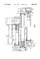
- FIG. 2is a cross-sectional view of the preferred arm according to the invention.
- FIG. 3is a three-dimensional illustrative view of the preferred structure of the transducers used in the invention.
- FIG. 4is close-up partial cross-sectional view of a transfer member and its adjacent joints.
- FIG. 4ais a diagrammatic cross-sectional end view of FIG. 4 taken along line 4a--4a
- FIG. 5is a three-dimensional illustrative view of a dual projection yoke for mechanically connecting adjacent joints.
- FIG. 6is a three-dimensional illustrative view of a pedestal for connecting a hinge joint to a transfer member.
- FIG. 7is a cross-sectional view of a hinge joint taken along a plane defined by the joint's rotational axis and the major axis of its adjacent transfer member.
- FIG. 8is a three-dimensional illustrative view of a portion of a slip-ring sub-assembly.
- FIG. 9is a cross-sectional view taken perpendicular to the axis of rotation of the slip-ring sub-assembly shown in FIG. 8.
- FIG. 10is a top plan view of a portion of a slip-ring sub-assembly according to the invention.
- FIG. 11is an end view of the slip-ring sub-assembly of FIG. 10 taken along line 11--11.
- FIG. 12is a diagrammatic cross-sectional side view taken parallel to the axis of rotation of a portion of a slip-ring sub-assembly.
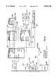
- FIG. 13is a diagrammatic functional block diagram of the electronic components of the invention.
- FIG. 14is an electronic block diagram of the major components of a member mounted printed circuit board of the invention.
- FIG. 1a three-dimensional diagrammatic view of the spatial coordinate measuring machine arm 1 according to the invention.
- the armcomprises a stationary support base 2, three rigid transfer members 3,4,5 and a probe 6 which are interconnected with a plurality of joints 7a,7 b,7c,7d,7e,7f.
- Each of the jointsis dedicated to a single degree of freedom and allows rotational movement about a dedicated axis 10a-10f which is fixed relative to that joint.
- the jointscan be divided into two categories, namely: 1) those joints 7a,7c,7e which allow the swiveling motion associated with a specific member (hereinafter, “swiveling joints”), and 2) those joints 7b,7d,7f which allow a change in the relative angle formed between two adjacent members or between the probe and its adjacent member (hereinafter, “hinge joints”).
- swiveling jointsthose joints 7a,7c,7e which allow the swiveling motion associated with a specific member
- joints 7b,7d,7fwhich allow a change in the relative angle formed between two adjacent members or between the probe and its adjacent member
- Each of two pairs of joints 7b,7c and 7d,7e,are connected via a yoke, 8 and 9 respectively.
- Each hinge joint 7b,7d,7fis connected to its adjacent transfer member 3,4,5 by means of a pedestal 11,12,13, respectively.
- the pedestalprecisely orients the rotational axis of its hinge joint orthogonally to the major axis of its adjacent transfer member.
- the swiveling joints 7a,7c,7eare unlimited in their range of motion. This capability is accomplished without using any "stack" type structures described earlier. This is in stark contrast to prior designs.
- the preferred hinge joints 7b,7d,7eare limited by interference between adjacent members. Although this interference is not required, as shown by Raab (U.S. Pat. No. 5,402,582), which utilizes offset or skewed adjacent members; it has been found that the preferred approach offers a symmetrical design without sacrificing rigidity, and a sleeker profile which more conveniently allows access through narrower passageways. Non-symmetrical designs must cope with greater momentary forces generated by the orthogonally arranged members.
- FIG. 2shows cross-sectional view of the preferred coordinate measuring arm.
- Six joints 7a-7fare connected by three transfer members 3-5, two yokes 8,9, and three pedestals 11-13.
- the inventionis able to achieve unlimited motion in the swiveling joints by eliminating the need for a continuous, flexible wire running between the joints straddling a swiveling joint.
- the preferred means for conducting power and signals through these jointsreplaces wires with a multi-conductor electrical slip-ring sub-assembly. Therefore, there is a slip-ring sub-assembly 14,15,16 operatively associated with each swiveling joint 7a,7c,7e.
- the slip-ring sub-assemblywill be described in detail later.
- Each hinge or swiveling jointhas its own dedicated motion transducer in the form of an optical encoder 17a-17f.
- Hinge joint encoders 17b, 17d and 17fare shown hidden in FIG. 2. Since each encoder forms an integral part of each joint by providing primary rotational bearings, it is important that the encoder be structurally rugged.
- a encoder 17ccomprises a generally cylindrical body 20 having an outer housing comprising a cup-shaped casing 21 and a circular face plate 22.
- a central axle 23is rotatively mounted to the body on internal bearings and extends through the face plate.
- An electrical cable 24carries power to the encoder and output signals from the encoder through an aperture 25 in the housing.
- the preferred encoderis a ROD 450.0000-5000 model analog optical encoder available from Heidenhain of Traunrent, Germany. These encoders offer structural ruggedness by having a large central axle and bearing. Ideally, this encoder is capable of resolutions of about 5000 cycles per revolution.
- Digital encodersare available and could be used in the invention; however, currently available designs are not preferred. Some "digital" encoders which use simple clipping circuits to generate a square, rather than sine wave output, suffer from inferior resolution. True digital encoders having onboard digitizing circuitry currently suffer from being too bulky. However, as circuit board sizes decrease, adequate encoders may become available. Current digital encoders are also more expensive and less versatile with respect to the type of systems they are capable of interfacing.
- the encoder housingforms part of the outer surface of the arm, slight modifications to the encoders may be required. Power and output wires should not be exposed and should therefore run through portions of the housing having contact with internal cavities of the arm. Means for mounting the encoders to the arm may require additional modifications, however, preferred mounting occurs primarily through screw attachment to the structurally rugged face plate.
- Each transfer member 4is in the form of a dual concentric tubular structure having an inner tubular shaft 30 rotatively mounted coaxially within an outer tubular sheath 31 by means of a first bearing 32 mounted proximately to a first end of the member 4 adjacent to a hinge joint 7d, and a second bearing comprising a slip-ring sub-assembly 15 in combination with the encoder 17c of an adjacent swiveling joint 7c located at an opposite end of the member.
- the shaft 30is mounted to the hinge joint 7d by fastening means such as nut and screws 33 connecting the shaft end flange 34 to base plate 35 of pedestal 12.
- the sheath 31is mounted to the swiveling joint 7c by fastening means such as nut and screws 36 connecting the sheath end flange 37 to the yoke 8.
- the amount of axis misalignment between encoder and the swiveling shaftare kept to a minimum, thereby increasing precision.
- the shaft 30comprises a rigid cylindrical tubular body 40 having opposite ends to which are bonded first and second end-caps 41,42.
- the end-capsare glued to the body in such a way that the resulting member is precisely and accurately balanced.
- the preferred method of assuring this balanceinvolves allowing the glue to cure while the assembled member is being revolved.
- the sheath 31comprises a rigid tubular body 43 having similarly attached first and second end-caps 44,45.
- first end-cap 42 of the shaft 30provides an outer surface for mounting the first bearing 32, and a flange 34 for attachment to the pedestal 12.
- first end-cap 45 of the sheath 31has female coupling flange 47 for engaging the outer surface of the first bearing 32.
- the second end-cap 41 of the shaft 30is integral with the central axle 50 of the slip-ring sub-assembly 15 dedicated to swiveling joint 7c.
- An access hole 51extends through a side wall of both the sheath 31 and the second end-cap 44 of the sheath to allow for the loosening of the split collar clamp 53 which firmly couples the central axle 50 of the slip-ring to the swiveling joint encoder axle 23. This allows for quick decoupling during repair or reconfiguration.
- the end-capsare preferably made from an easily machinable, inexpensive, light-weight, rigid material such as aluminum.
- cylindrical tubes for both sheath and shaftare preferred because they offer construction simplicity, rigidity, light weight, and space inside for the printed circuit board 46 feature of the invention. Also, as shown in FIG. 4a, they allow a concentric mounting of a shaft tubular body 40 having an outer diameter 48 approaching the inner diameter 49 of the sheath tubular body 43, thereby increasing rigidity while maintaining low weight and a sleek profile. Therefore, the shaft tubular body outer diameter is preferably at least 50%, and most preferably at least 75% of the inner diameter of the sheath tubular body.
- the closeness of these two diametersis limited by the interposition of the sheath's first end-cap 45 between the diameters.
- the end-capcould be designed to bond with the outer surface of the sheath body, thereby allowing the two diameters to be closer, it has been found that the preferred design is less expensive with respect to machining tolerances while maintaining adequate rigidity.
- the tubesare preferably made from a light-weight, rigid material such as epoxy bonded carbon graphite which inexpensively offers a strength to weight ratio in excess of that of steel.
- a light-weight, rigid materialsuch as epoxy bonded carbon graphite which inexpensively offers a strength to weight ratio in excess of that of steel.
- carbon graphiteAnother advantage of carbon graphite is that it has a low thermal expansion coefficient.
- the shaft and sheathmay be made from lighter, inexpensive, and easily machined material such as aluminum, or the preferred carbon graphite.
- a lighter overall armprovides less operator fatigue, reducing the need for complex counterbalances or springs which may reduce precision.
- the inventioncan be easily modified to incorporate counterbalance mechanisms. Also, the amount play or backlash inherent in a coupled system is significantly reduced by having direct coupling between the various components.
- Each of the dual projection yokes 8,9comprises a fork structure with a base 60 and dual support projections 61 and 62.
- the base 60is mounted to the face plate of the encoder 17e of a swiveling joint using fastening screws 69.
- Each support projectionmounts to the pivoting axle of an adjacent hinge joint by means of a releasable stock-type split clamp 63,64, each having a hole 65,66 sized to allow engagement with the axle. The tightness of the clamp is adjusted by end screws 67,68.
- Each pedestal 11,12,13comprises a circular base plate 35 which mounts to the first end-cap 42 of a member shaft using fastening means such as nuts and screws 33.
- the base plate 35is integral with two parallel, facing circular coupling plates 70,71 spaced apart to allow for the placement of an encoder between them.
- Each coupling platecomprises a stock-type split clamp 70a,71a for mounting bearings 75,76. The tightness of the clamp is adjusted by end screws which engage the lower portions of the plates through recesses 70b,71b.
- One coupling plate 71attaches directly to the encoder's face plate 22a using screw fastening means 73.
- the first bearing 76allows the encoder axle 23a to freely rotate with respect to the pedestal.
- the other coupling plate 70supports the encoder 17d from the back using an O-ring spacer 74 contacting the encoder and a bearing 75 mounted to the coupling plate.
- the second bearing 75allows a dummy axle 77 to freely rotate with respect to the pedestal.
- the dummy axle 77 and the encoder axle 23aform the pivoting axle for this hinge joint.
- Protective end-guards 78,79are attached to the axles using screw fastening means.
- the pedestal 12also provides a bracket 80 for mounting the printed circuit board 46 of the hinge joint's adjacent member.
- Wiring 83 soldered to the circuit board 46passes to the encoder 17d through an opening 81 in the base plate 35 and an O-ring type bushing 82 traversing the space between the encoder and pedestal.
- Wiring 58 between the printed circuit board (PCB) 46 and its adjacent slip-ring sub-assemblyconnects to the PCB using an electrical connector 59 common in the art.
- a similar yoke and pedestalconnects joints 7b and 7c.
- a yoke having encoder straddling dual projections, although not necessary,is preferred because it strengthens the joint making it less susceptible to moment forces acting on the joint.
- the joint 7f closest to the probe 6does not require a dual projection yoke due to the light loading of this joint.
- a larger probemay require a dual projection yoke.
- the half yoke 90 with a single support projection 91also provides the operator greater comfort and ease of use while grasping the probe.
- Each slip-ring sub-assemblycomprises a central cylindrical shaft or axle 50 along which has been mounted a plurality of cylindrical contact rings 102 each made of copper, bronze or other inexpensive electrically conductive material.
- the materialneed not be especially durable because of the light loading and low rate of revolution to which the sub-assembly will be subjected.
- Adjacent contact ringsare separated from each other by spacers 103 of insulating material.
- Each contact ringhas a central, V-shaped groove 104 embedded circumferentially around its outer surface.
- the grooveis sized to provide tracking and electrical contact for a portion of a contact wire 105b stretched transversely across the contact ring.
- the contact wireis made from an electrically conductive, ductile, corrosion resistant and somewhat strong material. The preferred material is silver because of its availability and positive wear characteristics when contacting copper or bronze.
- Each wireis in the form of a loop mounted on two prongs 106,107 of a support rack which straddles the contact ring and axle combination. Therefore, each wire has first and second portions 108,109 contacting the top and bottom of the contact ring 102.
- the wireis biased toward the ring by means of a spring 110 located on a section of the loop contacting one of the prongs 106 of the support rack.
- the spring portion 111 of the loopis located on the opposite prong 107 so that the spring forces acting on the slip ring are balanced.
- the wiresare kept in place by the V-shaped grooves and U-shaped channels 112 set into the surface 113 of the prong facing away from the axle 50.
- the slip-ring axle 50is rotatively mounted concentrically within a pair of circular support spacers 115,116 which are each connected to opposite ends of the prongs 106,107 of the wire loop support rack.
- the spacersare additionally braced by bracing members (removed in FIG. 10) attached by screw means 114.
- the outer cylindrical surface of each of the support spacersis sized to lodge the slip-ring sub-assembly concentrically within the second end-cap of the sheath.
- the slip-ring sub-assembly 16is mechanically coupled to a swiveling joint encoder axle by means of a slotted female coupling 117 and a removable split collar clamp 53. This allows for quick decoupling during repair or reconfiguration. Note that the fastening screws 118,119 of the split collar clamp engage from opposite directions so as to provide balanced axial symmetry, and to allow for screwdriver access from one orientation by simply revolving the axle 50 one-half turn (180 degrees).
- connection between the adjacent swiveling joint 7c and the contact wires 105a,105bis in the form of two groups of connecting wires, each associated with a mated pair of detachable electrical connectors 54a,54b,55a,55blocated on opposite sides of the slip-ring sub-assembly.
- each contact wire loop 105bthere is a connecting wire 56b(one for each loop) soldered to the loop at a point proximate to the supporting rack prong 107 which does not contact the spring 110. Therefore, under this arrangement, the connecting wires are divided into two groups. One group (containing 56b) leads from the loops to the upper connector 54b, and the other group (containing 56a) leads to the lower connector 55b.
- Electrical connection between the contact rings 102 and a more distal PCBcan be in the form of connecting wires 125a-125d (one for each contact ring) running through axial channels 126 in the slip-ring sub-assembly axle 50.
- the channelsare provided by a crenellated tube 127 concentrically mounted around the axle 50 beneath the contact rings 102. Electrical contact is made to a ring inserting the end 128a,128b of a connecting wire into a radial well 129 set into the inner surface of each contact ring.
- the connecting wires 125a-125dcongregate at the distal end 130 of the sub-assembly where they bundle into a multi-conductor cable 58 leading to a more distal PCB 46.
- Each preferred slip-ring sub-assemblyhas nine conductive contact rings 102.
- Analog signals emanating from the encodersare fed via wiring to signal reconditioning units 203,204,205 each mounted on a printed circuit board ("PCB") located in the adjacent transfer member more proximate to the base.
- PCBprinted circuit board
- signals from the probe 6 (if there are any) and encoder 17fflow on wiring to PCB 205.
- Signals from encoders 17e and 17dflow to PCB 204.
- signals from encoders 17c and 17bflow to PCB 203.
- Signals from encoder 17aflow to a PCB 202 located on the base 2.
- Each circuit boardcomprises microprocessor means for reconditioning the analog signals from the encoders into digital information to be sent to the recording and analysis system.
- the PCBstherefore, are capable of receiving and digitizing analog data from their dedicated encoders or probe, and communicating with the recorder/analyzer.
- Fine positioningoccurs only when the microprocessor receives a latching signal 301 from the recorder/analyzer.
- a latching signalmay be caused by any number of events such as the operator pushing a button on the probe or events generated by the recorder/analyzer software.
- a latching signal 301causes the microprocessor on each of the PCBs to initiate a fine positioning reading of all the encoders in sync at a specific instant in time.
- the precise voltage from each of the signals of each encoderis digitized and combined with the counter to derive a digitized fine position data word which is stored in the microprocessor until it can transmit its data to the recorder/analyzer.
- two linesare devoted to ground 302, and another 305 as a shield.
- Two lines 303supply power at+10 volts DC to the microprocessors, their attendant circuitry and the encoders. Double lines are used increase reliability and to divide power supply currents. This allows for the use of lighter gauge and hence lighter weight and more flexible wiring.
- Another line 304supplies +12 volts DC to power the probe 6 if needed.
- One sync line 301is devoted to carrying the latching signal.
- the two remaining linesare devoted to carrying multiplexed data 310 to and from each of the PCBs. Two lines are used to support the preferred RS-485 data communication standard.
- Analog data from the encoderscomprises an index line 321 which signals when the zero position of the encoder is reached, and the two sinusoidal lines A 322 and B323. Comparators 324 effectively transform these signals into square waves monitored by a programmable field programmable gate array (FPGA) logic module 330 thereby tracking the coarse positioning of the encoders.
- the FPGA modulealso interprets any latching signal arriving on the sync line 301 and directs a voltage hold circuit 325 to initiate a hold of the current voltage outputs of the encoders. The hold circuit maintains this voltage long enough for the programmable microprocessor 340 to digitally sample the held voltage value. Programming for the microprocessor is stored in a memory module 350. Command communication carried on data 326 and address lines 327 between the microprocessor 340, the FPGA 330 and the memory module 350 is routed by a programmable data and address line monitoring unit 360.
- FIG. 14The specific identification of the components in FIG. 14 is provided only for example. Those familiar with the art could substantially modify the components shown and their interactions without departing from the PCBs primary functions and hence, the invention.
- Another advantage of this approachis that it allows the use of fewer electrical connectors (three per member), thereby increasing reliability. Connectors are provided only at one end of the PCB and at the slip-ring sub-assemblies. If data was further multiplexed and/or modulated upon the power lines, fewer connectors may be necessary.
- Another advantage of the present inventionis that it allows for modular disassembly and replacement of component parts. For example to replace encoder 17c one would first loosen split collar clamp 53 through holes 51,52. Next one would remove screws 36 fastening the sheath 31 of member 4 to the yoke 8 of joint 7c. The member 4 would then separate from the joint 7c, and electrical connector pairs 54a, 54b and 55a,55b would disconnect. Encoder-to-yoke mounting screws 69 would then be exposed. Removing these screws would allow for removal of the encoder save for wiring leading to the circuit board in member 3. Completely removing the encoder 17c would then require cutting the wiring or accessing the circuit board in member 3.
- the slip-ringmay be reduced to as few as two conductors, one being the power/signal line, and the other being a ground.
- power and signal transmission meansother than a slip-ring may be used.
- electromagnetic transmission through the airmay be accomplished using radio waves, microwaves, light waves, or infrared waves.
- Fiber optic cables having swivel connectorsmay also be adapted for use in the arm.
Landscapes
- Physics & Mathematics (AREA)
- General Physics & Mathematics (AREA)
- Length Measuring Devices With Unspecified Measuring Means (AREA)
- Measuring Pulse, Heart Rate, Blood Pressure Or Blood Flow (AREA)
- Vehicle Body Suspensions (AREA)
- Transmission And Conversion Of Sensor Element Output (AREA)
Abstract
Description
Claims (17)
Priority Applications (6)
| Application Number | Priority Date | Filing Date | Title |
|---|---|---|---|
| US08/636,590US5829148A (en) | 1996-04-23 | 1996-04-23 | Spatial measuring device |
| EP10183916.5AEP2270419B1 (en) | 1996-04-23 | 1997-04-22 | Spatial measuring device |
| PCT/US1997/006893WO1997040336A1 (en) | 1996-04-23 | 1997-04-22 | Spatial measuring device |
| EP97922439AEP0895574B1 (en) | 1996-04-23 | 1997-04-22 | Spatial measuring device |
| AT97922439TATE557257T1 (en) | 1996-04-23 | 1997-04-22 | DEVICE FOR MEASURING SPATIAL COORDINATES |
| CA002252481ACA2252481C (en) | 1996-04-23 | 1997-04-22 | Spatial measuring device |
Applications Claiming Priority (1)
| Application Number | Priority Date | Filing Date | Title |
|---|---|---|---|
| US08/636,590US5829148A (en) | 1996-04-23 | 1996-04-23 | Spatial measuring device |
Publications (1)
| Publication Number | Publication Date |
|---|---|
| US5829148Atrue US5829148A (en) | 1998-11-03 |
Family
ID=24552534
Family Applications (1)
| Application Number | Title | Priority Date | Filing Date |
|---|---|---|---|
| US08/636,590Expired - LifetimeUS5829148A (en) | 1996-04-23 | 1996-04-23 | Spatial measuring device |
Country Status (4)
| Country | Link |
|---|---|
| US (1) | US5829148A (en) |
| EP (2) | EP0895574B1 (en) |
| AT (1) | ATE557257T1 (en) |
| WO (1) | WO1997040336A1 (en) |
Cited By (119)
| Publication number | Priority date | Publication date | Assignee | Title |
|---|---|---|---|---|
| USD423534S (en)* | 1999-02-19 | 2000-04-25 | Faro Technologies, Inc. | Articulated arm |
| US6151789A (en)* | 1998-07-01 | 2000-11-28 | Faro Technologies Inc. | Adjustable handgrip for a coordinate measurement machine |
| US6253458B1 (en)* | 1998-12-08 | 2001-07-03 | Faro Technologies, Inc. | Adjustable counterbalance mechanism for a coordinate measurement machine |
| US6298566B1 (en)* | 1998-01-09 | 2001-10-09 | Fujitsu Takamisawa Component Limited | Angular-displacement detecting device |
| US6468096B1 (en)* | 1999-01-21 | 2002-10-22 | Sony Corporation | Rotating bearing device, joint device, wiring device of joint mechanism, and robot |
| US6523427B1 (en)* | 2000-11-01 | 2003-02-25 | Dresser, Inc. | Temperature sensing probe assembly for fluid meter |
| ES2185431A1 (en)* | 1999-02-19 | 2003-04-16 | Univ Valladolid | Modular structure portable machine for measuring dimensions in objects and controlling the manufacturing process for surface generation |
| US6598306B2 (en)* | 2001-04-17 | 2003-07-29 | Homer L. Eaton | Self-loading spatial reference point array |
| US20030167647A1 (en)* | 2002-02-14 | 2003-09-11 | Simon Raab | Portable coordinate measurement machine |
| US6668466B1 (en) | 2000-10-19 | 2003-12-30 | Sandia Corporation | Highly accurate articulated coordinate measuring machine |
| EP1387144A1 (en)* | 2002-07-29 | 2004-02-04 | Idiada Automotive Technology, S.A. | Dynamic measurement of an object's relative position, in particular of a wheel of a vehicle |
| USD490831S1 (en) | 2002-02-14 | 2004-06-01 | Faro Technologies, Inc. | Portable coordinate measurement machine |
| US20040103547A1 (en)* | 2002-02-14 | 2004-06-03 | Simon Raab | Portable coordinate measurement machine |
| USD491210S1 (en) | 2003-02-13 | 2004-06-08 | Faro Technologies, Inc. | Probe for a portable coordinate measurement machine |
| US20040111908A1 (en)* | 2002-02-14 | 2004-06-17 | Simon Raab | Method for improving measurement accuracy of a protable coordinate measurement machine |
| US20040113813A1 (en)* | 2002-12-10 | 2004-06-17 | Henson John W. | Wireless transmitting pressure measurement device |
| US20040148791A1 (en)* | 2003-02-05 | 2004-08-05 | Eaton Homer L. | Articulation measuring arm having rotatable part-carrying platen |
| USD496595S1 (en) | 2002-02-14 | 2004-09-28 | Faro Technologies, Inc. | Portable coordinate measurement machine portion |
| US20040190593A1 (en)* | 2003-03-27 | 2004-09-30 | Ferguson Walter J. | Temperature measurement device |
| US20040210553A1 (en)* | 2003-04-15 | 2004-10-21 | Eaton Homer L. | Spatial coordinate-based method for identifying work pieces |
| USD497815S1 (en) | 2002-02-14 | 2004-11-02 | Faro Technologies, Inc. | Portable coordinate measurement machine portion |
| US20050016008A1 (en)* | 2002-02-14 | 2005-01-27 | Simon Raab | Method for providing sensory feedback to the operator of a portable measurement machine |
| US20050095877A1 (en)* | 2003-10-29 | 2005-05-05 | Romain Granger | Connection device associated with an arm of an articulated three-dimensional measuring appliance |
| USD505144S1 (en)* | 2002-02-14 | 2005-05-17 | Faro Technologies, Inc. | Laser scanner for a portable coordinate measurement machine |
| US6908310B1 (en)* | 2004-03-11 | 2005-06-21 | Deepsea Power & Light | Slip ring assembly with integral position encoder |
| US20050151963A1 (en)* | 2004-01-14 | 2005-07-14 | Sandeep Pulla | Transprojection of geometry data |
| US20050166413A1 (en)* | 2003-04-28 | 2005-08-04 | Crampton Stephen J. | CMM arm with exoskeleton |
| US20050190999A1 (en)* | 2000-08-05 | 2005-09-01 | Renishaw Plc | Bearing arrangement |
| US20060010701A1 (en)* | 2004-07-16 | 2006-01-19 | Tesa Sa | Orientable probe |
| US20060098712A1 (en)* | 2003-03-27 | 2006-05-11 | Dresser, Inc., A Delaware Corporation | Temperature measurement device |
| US20060101660A1 (en)* | 2004-11-18 | 2006-05-18 | Tokyo Seimitsu Co., Ltd. | Detector supporting mechanism |
| WO2006111630A1 (en)* | 2005-04-20 | 2006-10-26 | Romer | Three-dimensional measuring apparatus with articulated arms comprising a plurality of pivot pins |
| US7246030B2 (en) | 2002-02-14 | 2007-07-17 | Faro Technologies, Inc. | Portable coordinate measurement machine with integrated line laser scanner |
| US20070163137A1 (en)* | 2003-10-21 | 2007-07-19 | Renishaw Plc | Metrology instruments |
| US20070163134A1 (en)* | 2004-01-14 | 2007-07-19 | Homer Eaton | Automated robotic measuring system |
| US20070256311A1 (en)* | 2006-05-01 | 2007-11-08 | Paul Ferrari | Sealed battery for coordinate measurement machine |
| US20080127501A1 (en)* | 2006-11-20 | 2008-06-05 | Eaton Homer L | Coordinate measurement machine with improved joint |
| WO2008080142A1 (en)* | 2006-12-22 | 2008-07-03 | Romer, Inc. | Improved joint axis for coordinate measurement machine |
| EP2003419A1 (en) | 2005-04-06 | 2008-12-17 | Faro Technologies, Inc. | Improved portable coordinate measurement machine |
| US20090010740A1 (en)* | 2008-03-28 | 2009-01-08 | Paul Ferrari | Coordinate measuring machine with rotatable grip |
| US20090013547A1 (en)* | 2007-07-09 | 2009-01-15 | Paul Ferrari | Joint for coordinate measurement device |
| US20090083985A1 (en)* | 2007-09-28 | 2009-04-02 | Romer / Cimcore | Coordinate measurement machine |
| US7519493B2 (en) | 2002-02-14 | 2009-04-14 | Faro Technologies, Inc. | Portable coordinate measurement machine with integrated line laser scanner |
| US20090205088A1 (en)* | 2006-04-27 | 2009-08-13 | Metris N.V. | Optical Scanning Probe |
| US20090199421A1 (en)* | 2008-02-07 | 2009-08-13 | Eaton Homer L | Motorized coordinate measuring device |
| USD599226S1 (en) | 2008-04-11 | 2009-09-01 | Hexagon Metrology, Inc. | Portable coordinate measurement machine |
| US20090241360A1 (en)* | 2008-03-28 | 2009-10-01 | Hogar Tait | Systems and methods for improved coordination acquisition member comprising calibration information |
| US20090271996A1 (en)* | 2008-05-05 | 2009-11-05 | Paul Ferrari | Systems and methods for calibrating a portable coordinate measurement machine |
| US20090313844A1 (en)* | 2008-06-20 | 2009-12-24 | Swanson David W | Measuring device with extensible cord and method |
| US20100005673A1 (en)* | 2008-07-10 | 2010-01-14 | Raffaelo Tomelleri | Connection device for articulated arm measuring machines |
| FR2935043A1 (en)* | 2008-08-14 | 2010-02-19 | Hexagon Metrology Sas | Three-dimensional measurement apparatus for measuring rotational angles, has reinforcement elements respectively extending on lengths of arms while supporting elements respectively on arms to limit flexion during handling of apparatus |
| EP2177868A2 (en) | 2008-10-16 | 2010-04-21 | Hexagon Metrology, Inc | Articulating measuring arm with laser scanner |
| US7805854B2 (en) | 2006-05-15 | 2010-10-05 | Hexagon Metrology, Inc. | Systems and methods for positioning and measuring objects using a CMM |
| US20100325907A1 (en)* | 2009-06-30 | 2010-12-30 | Hexagon Metrology Ab | Coordinate measurement machine with vibration detection |
| USRE42082E1 (en) | 2002-02-14 | 2011-02-01 | Faro Technologies, Inc. | Method and apparatus for improving measurement accuracy of a portable coordinate measurement machine |
| US7881896B2 (en) | 2002-02-14 | 2011-02-01 | Faro Technologies, Inc. | Portable coordinate measurement machine with integrated line laser scanner |
| US20110107613A1 (en)* | 2009-11-06 | 2011-05-12 | Hexagon Metrology Ab | Cmm with modular functionality |
| US20110170534A1 (en)* | 2010-01-11 | 2011-07-14 | Faro Technologies, Inc. | Method and apparatus for synchronizing measurements taken by multiple metrology devices |
| US20110178758A1 (en)* | 2010-01-20 | 2011-07-21 | Faro Technologies, Inc. | Integrated part temperature measurement system |
| US20110178764A1 (en)* | 2010-01-20 | 2011-07-21 | Faro Technologies, Inc. | Portable Articulated Arm Coordinate Measuring Machine with Multi-Bus Arm Technology |
| US20110176148A1 (en)* | 2010-01-20 | 2011-07-21 | Faro Technologies, Inc. | Coordinate measuring machine having an illuminated probe end and method of operation |
| USD643319S1 (en) | 2010-03-29 | 2011-08-16 | Hexagon Metrology Ab | Portable coordinate measurement machine |
| US20110213247A1 (en)* | 2010-01-08 | 2011-09-01 | Hexagon Metrology, Inc. | Articulated arm with imaging device |
| EP2384851A1 (en)* | 2010-05-03 | 2011-11-09 | Tesa Sa | Coordinate Measuring System with rotatory adapter |
| CN102252639A (en)* | 2010-04-26 | 2011-11-23 | 特莎有限公司 | Measuring system |
| US8127458B1 (en) | 2010-08-31 | 2012-03-06 | Hexagon Metrology, Inc. | Mounting apparatus for articulated arm laser scanner |
| US8352212B2 (en) | 2009-11-18 | 2013-01-08 | Hexagon Metrology, Inc. | Manipulable aid for dimensional metrology |
| WO2013108129A1 (en) | 2012-01-20 | 2013-07-25 | Hexagon Technology Center Gmbh | Locking counterbalance for a cmm |
| WO2013144293A1 (en) | 2012-03-30 | 2013-10-03 | Nikon Metrology Nv | Improved optical scanning probe |
| WO2013182909A1 (en) | 2012-06-08 | 2013-12-12 | Hexagon Technology Center Gmbh | System and method for a wireless feature pack |
| US8615893B2 (en) | 2010-01-20 | 2013-12-31 | Faro Technologies, Inc. | Portable articulated arm coordinate measuring machine having integrated software controls |
| US8638446B2 (en) | 2010-01-20 | 2014-01-28 | Faro Technologies, Inc. | Laser scanner or laser tracker having a projector |
| US8677643B2 (en) | 2010-01-20 | 2014-03-25 | Faro Technologies, Inc. | Coordinate measurement machines with removable accessories |
| US20140157609A1 (en)* | 2012-12-07 | 2014-06-12 | Transtron Inc. | Displacement detecting device |
| US8832954B2 (en) | 2010-01-20 | 2014-09-16 | Faro Technologies, Inc. | Coordinate measurement machines with removable accessories |
| US20140303631A1 (en)* | 2013-04-05 | 2014-10-09 | Thornberry Technologies, LLC | Method and apparatus for determining the orientation and/or position of an object during a medical procedure |
| WO2014164159A1 (en) | 2013-03-12 | 2014-10-09 | Hexagon Metrology, Inc. | Cmm with flaw detection system |
| US8875409B2 (en) | 2010-01-20 | 2014-11-04 | Faro Technologies, Inc. | Coordinate measurement machines with removable accessories |
| US8898919B2 (en) | 2010-01-20 | 2014-12-02 | Faro Technologies, Inc. | Coordinate measurement machine with distance meter used to establish frame of reference |
| US20150093180A1 (en)* | 2013-09-27 | 2015-04-02 | Siemens Aktiengeselschaft | Coupling unit and method for determining an alignment of the coupling unit |
| US8997362B2 (en) | 2012-07-17 | 2015-04-07 | Faro Technologies, Inc. | Portable articulated arm coordinate measuring machine with optical communications bus |
| US20150176972A1 (en)* | 2013-12-18 | 2015-06-25 | Hexagon Metrology, Inc. | Ultra-portable coordinate measurement machine |
| WO2015095616A1 (en) | 2013-12-18 | 2015-06-25 | Hexagon Metrology, Inc. | Ultra-portable coordinate measurement machine comprising a tracktable device and a harness configured to mount on a human |
| US9074883B2 (en) | 2009-03-25 | 2015-07-07 | Faro Technologies, Inc. | Device for optically scanning and measuring an environment |
| US9113023B2 (en) | 2009-11-20 | 2015-08-18 | Faro Technologies, Inc. | Three-dimensional scanner with spectroscopic energy detector |
| US9163922B2 (en) | 2010-01-20 | 2015-10-20 | Faro Technologies, Inc. | Coordinate measurement machine with distance meter and camera to determine dimensions within camera images |
| WO2015157837A1 (en)* | 2014-04-15 | 2015-10-22 | Halliburton Energy Services, Inc. | Slip ring with a tensioned contact element |
| US9168654B2 (en) | 2010-11-16 | 2015-10-27 | Faro Technologies, Inc. | Coordinate measuring machines with dual layer arm |
| US9210288B2 (en) | 2009-11-20 | 2015-12-08 | Faro Technologies, Inc. | Three-dimensional scanner with dichroic beam splitters to capture a variety of signals |
| WO2015191774A1 (en) | 2014-06-11 | 2015-12-17 | Hexagon Metrology, Inc. | Articulating cmm probe |
| ITUB20159887A1 (en)* | 2015-12-21 | 2016-03-21 | Tomelleri Eng S R L | SYSTEM FOR READING AND CORRECTING THE CORNERS OF THE AXES IN PORTABLE MEASURING MACHINES WITH ARTICULATED ARMS |
| US20160102965A1 (en)* | 2014-10-08 | 2016-04-14 | Faro Technologies, Inc. | Coordinate measurement machine with redundant energy sources |
| US9329271B2 (en) | 2010-05-10 | 2016-05-03 | Faro Technologies, Inc. | Method for optically scanning and measuring an environment |
| US9372265B2 (en) | 2012-10-05 | 2016-06-21 | Faro Technologies, Inc. | Intermediate two-dimensional scanning with a three-dimensional scanner to speed registration |
| US9417056B2 (en) | 2012-01-25 | 2016-08-16 | Faro Technologies, Inc. | Device for optically scanning and measuring an environment |
| US9417316B2 (en) | 2009-11-20 | 2016-08-16 | Faro Technologies, Inc. | Device for optically scanning and measuring an environment |
| US9513107B2 (en) | 2012-10-05 | 2016-12-06 | Faro Technologies, Inc. | Registration calculation between three-dimensional (3D) scans based on two-dimensional (2D) scan data from a 3D scanner |
| US9529083B2 (en) | 2009-11-20 | 2016-12-27 | Faro Technologies, Inc. | Three-dimensional scanner with enhanced spectroscopic energy detector |
| US9551575B2 (en) | 2009-03-25 | 2017-01-24 | Faro Technologies, Inc. | Laser scanner having a multi-color light source and real-time color receiver |
| US9607239B2 (en) | 2010-01-20 | 2017-03-28 | Faro Technologies, Inc. | Articulated arm coordinate measurement machine having a 2D camera and method of obtaining 3D representations |
| US20170097221A1 (en)* | 2015-10-06 | 2017-04-06 | Mitutoyo Corporation | Measuring probe and measuring probe system |
| US9628775B2 (en) | 2010-01-20 | 2017-04-18 | Faro Technologies, Inc. | Articulated arm coordinate measurement machine having a 2D camera and method of obtaining 3D representations |
| US9803973B1 (en) | 2017-04-13 | 2017-10-31 | Sa08700334 | Ultra-light and ultra-accurate portable coordinate measurement machine |
| US10067231B2 (en) | 2012-10-05 | 2018-09-04 | Faro Technologies, Inc. | Registration calculation of three-dimensional scanner data performed between scans based on measurements by two-dimensional scanner |
| US20180299242A1 (en)* | 2017-04-13 | 2018-10-18 | Sa08700334 | Ultra-light and ultra-accurate portable coordinate measurement machine |
| US10175037B2 (en) | 2015-12-27 | 2019-01-08 | Faro Technologies, Inc. | 3-D measuring device with battery pack |
| WO2019067774A1 (en) | 2017-09-28 | 2019-04-04 | Hexagon Metrology, Inc. | Systems and methods for measuring various properties of an object |
| US10281259B2 (en) | 2010-01-20 | 2019-05-07 | Faro Technologies, Inc. | Articulated arm coordinate measurement machine that uses a 2D camera to determine 3D coordinates of smoothly continuous edge features |
| USD875573S1 (en) | 2018-09-26 | 2020-02-18 | Hexagon Metrology, Inc. | Scanning device |
| US10578424B2 (en)* | 2016-12-22 | 2020-03-03 | Carl Zeiss Industrielle Messtechnik Gmbh | Rotating/pivoting sensor system for a coordinate measuring apparatus |
| US10634478B2 (en) | 2017-04-13 | 2020-04-28 | Sa08700334 | Ultra-light and ultra-accurate portable coordinate measurement machine with serial bus capture |
| US11022434B2 (en) | 2017-11-13 | 2021-06-01 | Hexagon Metrology, Inc. | Thermal management of an optical scanning device |
| US11054237B2 (en) | 2019-04-04 | 2021-07-06 | Sa08700334 | Ultra-light and ultra-accurate portable coordinate measurement machine with unique base plate arrangement |
| US11092419B2 (en) | 2017-04-13 | 2021-08-17 | Sa08700334 | Ultra-light and ultra-accurate portable coordinate measurement machine with multi-piece joint engagement |
| WO2022140748A1 (en)* | 2020-12-24 | 2022-06-30 | Sa08700334 | Ultra-light and ultra-accurate portable coordinate measurement machine substantially immune to bearing assembly thermal effects |
| US11402205B2 (en)* | 2016-11-09 | 2022-08-02 | Salunda Limited | Sensor for a rotatable element |
| US11566880B2 (en) | 2017-04-13 | 2023-01-31 | Sa08700334 | Ultra-light and ultra-accurate portable coordinate measurement machine substantially immune to bearing assembly thermal effects |
| TWI813438B (en)* | 2022-09-07 | 2023-08-21 | 卡德爾股份有限公司 | Inspection method of metal processing parts |
| US11747126B1 (en) | 2022-05-20 | 2023-09-05 | Sa08700334 | Ultra-light and ultra-accurate portable coordinate measurement machine with reduced profile swivel joints |
Families Citing this family (4)
| Publication number | Priority date | Publication date | Assignee | Title |
|---|---|---|---|---|
| US6219928B1 (en)* | 1998-07-08 | 2001-04-24 | Faro Technologies Inc. | Serial network for coordinate measurement apparatus |
| GB2375026B (en)* | 1998-07-08 | 2002-12-18 | Faro Tech Inc | Serial network for coordinate measurement apparatus |
| US7006084B1 (en) | 2000-09-26 | 2006-02-28 | Faro Technologies, Inc. | Method and system for computer aided manufacturing measurement analysis |
| WO2025133850A1 (en)* | 2023-12-21 | 2025-06-26 | Car Bench - S.P.A. | System for the identification of structural damage in crashed motor vehicles |
Citations (13)
| Publication number | Priority date | Publication date | Assignee | Title |
|---|---|---|---|---|
| US3944798A (en)* | 1974-04-18 | 1976-03-16 | Eaton-Leonard Corporation | Method and apparatus for measuring direction |
| US4313263A (en)* | 1977-02-07 | 1982-02-02 | Rolls Royce Limited | Method and apparatus for use in co-ordinate measuring machines |
| US4388758A (en)* | 1980-03-05 | 1983-06-21 | Johannes Heidenhain Gmbh | Digital electrical angle-measuring device |
| US4593470A (en)* | 1982-07-14 | 1986-06-10 | Micro Control Systems, Inc. | Portable three dimensional graphics tablet |
| US4606696A (en)* | 1984-06-25 | 1986-08-19 | Slocum Alexander H | Mechanism to determine position and orientation in space |
| US4676002A (en)* | 1984-06-25 | 1987-06-30 | Slocum Alexander H | Mechanisms to determine position and orientation in space |
| US4703443A (en)* | 1984-02-16 | 1987-10-27 | Kabushiki Kaisha Toshiba | Device for measuring the shape of a three-dimensional object |
| US4888877A (en)* | 1987-11-26 | 1989-12-26 | Carl-Zeiss-Stiftung, Heidenhein/Brenz | Articulating head for a coordinate-measuring instrument |
| US5084981A (en)* | 1989-04-14 | 1992-02-04 | Renishaw Plc | Probe head |
| US5148377A (en)* | 1986-12-10 | 1992-09-15 | Mcdonald Gregory J | Coordinate measuring system |
| US5174039A (en)* | 1990-08-17 | 1992-12-29 | Kabushiki Kaisha Toshiba | Displacement-measuring apparatus, and static-pressure bearing device for use in the displacement-measuring apparatus |
| DE4140294A1 (en)* | 1991-06-26 | 1993-01-07 | Escher Wyss Gmbh | DEVICE FOR DETERMINING A SURFACE CONTOUR AND THE USE THEREOF |
| US5402582A (en)* | 1993-02-23 | 1995-04-04 | Faro Technologies Inc. | Three dimensional coordinate measuring apparatus |
Family Cites Families (7)
| Publication number | Priority date | Publication date | Assignee | Title |
|---|---|---|---|---|
| US4195250A (en)* | 1976-12-08 | 1980-03-25 | Ikegai Tekko Kabushiki Kaisha | Automatic measuring and tool position compensating system for a numerically controlled machine tool |
| EP0126195B1 (en)* | 1982-10-15 | 1987-07-15 | Renishaw plc | Position-sensing apparatus |
| US5155423A (en)* | 1986-02-18 | 1992-10-13 | Robotics Research Corporation | Industrial robot with servo |
| US4937759A (en)* | 1986-02-18 | 1990-06-26 | Robotics Research Corporation | Industrial robot with controller |
| JPH01234191A (en)* | 1988-03-10 | 1989-09-19 | Internatl Business Mach Corp <Ibm> | Manipulator-assembly |
| US5611147A (en) | 1993-02-23 | 1997-03-18 | Faro Technologies, Inc. | Three dimensional coordinate measuring apparatus |
| US5293107A (en)* | 1993-02-24 | 1994-03-08 | Fanuc Robotics North America, Inc. | Motorized rotary joint and method of constructing a modular robot utilizing same |
- 1996
- 1996-04-23USUS08/636,590patent/US5829148A/ennot_activeExpired - Lifetime
- 1997
- 1997-04-22WOPCT/US1997/006893patent/WO1997040336A1/enactiveApplication Filing
- 1997-04-22EPEP97922439Apatent/EP0895574B1/ennot_activeExpired - Lifetime
- 1997-04-22ATAT97922439Tpatent/ATE557257T1/enactive
- 1997-04-22EPEP10183916.5Apatent/EP2270419B1/ennot_activeExpired - Lifetime
Patent Citations (13)
| Publication number | Priority date | Publication date | Assignee | Title |
|---|---|---|---|---|
| US3944798A (en)* | 1974-04-18 | 1976-03-16 | Eaton-Leonard Corporation | Method and apparatus for measuring direction |
| US4313263A (en)* | 1977-02-07 | 1982-02-02 | Rolls Royce Limited | Method and apparatus for use in co-ordinate measuring machines |
| US4388758A (en)* | 1980-03-05 | 1983-06-21 | Johannes Heidenhain Gmbh | Digital electrical angle-measuring device |
| US4593470A (en)* | 1982-07-14 | 1986-06-10 | Micro Control Systems, Inc. | Portable three dimensional graphics tablet |
| US4703443A (en)* | 1984-02-16 | 1987-10-27 | Kabushiki Kaisha Toshiba | Device for measuring the shape of a three-dimensional object |
| US4676002A (en)* | 1984-06-25 | 1987-06-30 | Slocum Alexander H | Mechanisms to determine position and orientation in space |
| US4606696A (en)* | 1984-06-25 | 1986-08-19 | Slocum Alexander H | Mechanism to determine position and orientation in space |
| US5148377A (en)* | 1986-12-10 | 1992-09-15 | Mcdonald Gregory J | Coordinate measuring system |
| US4888877A (en)* | 1987-11-26 | 1989-12-26 | Carl-Zeiss-Stiftung, Heidenhein/Brenz | Articulating head for a coordinate-measuring instrument |
| US5084981A (en)* | 1989-04-14 | 1992-02-04 | Renishaw Plc | Probe head |
| US5174039A (en)* | 1990-08-17 | 1992-12-29 | Kabushiki Kaisha Toshiba | Displacement-measuring apparatus, and static-pressure bearing device for use in the displacement-measuring apparatus |
| DE4140294A1 (en)* | 1991-06-26 | 1993-01-07 | Escher Wyss Gmbh | DEVICE FOR DETERMINING A SURFACE CONTOUR AND THE USE THEREOF |
| US5402582A (en)* | 1993-02-23 | 1995-04-04 | Faro Technologies Inc. | Three dimensional coordinate measuring apparatus |
Cited By (328)
| Publication number | Priority date | Publication date | Assignee | Title |
|---|---|---|---|---|
| US6298566B1 (en)* | 1998-01-09 | 2001-10-09 | Fujitsu Takamisawa Component Limited | Angular-displacement detecting device |
| US6151789A (en)* | 1998-07-01 | 2000-11-28 | Faro Technologies Inc. | Adjustable handgrip for a coordinate measurement machine |
| US6253458B1 (en)* | 1998-12-08 | 2001-07-03 | Faro Technologies, Inc. | Adjustable counterbalance mechanism for a coordinate measurement machine |
| US6298569B1 (en)* | 1998-12-08 | 2001-10-09 | Faro Technologies, Inc. | Adjustable counterbalance mechanism for a coordinate measurement machine |
| US6468096B1 (en)* | 1999-01-21 | 2002-10-22 | Sony Corporation | Rotating bearing device, joint device, wiring device of joint mechanism, and robot |
| USD423534S (en)* | 1999-02-19 | 2000-04-25 | Faro Technologies, Inc. | Articulated arm |
| ES2185431B1 (en)* | 1999-02-19 | 2004-10-16 | Universidad De Valladolid | PORTABLE MODULAR STRUCTURE MACHINE TO MEASURE THE DIMENSIONS OF THE OBJECTS AND CONTROL THE MANUFACTURING PROCESS FOR THE GENERATION OF SURFACES. |
| ES2185431A1 (en)* | 1999-02-19 | 2003-04-16 | Univ Valladolid | Modular structure portable machine for measuring dimensions in objects and controlling the manufacturing process for surface generation |
| US7228641B2 (en)* | 2000-08-05 | 2007-06-12 | Renishaw Plc | Bearing arrangement |
| US20050190999A1 (en)* | 2000-08-05 | 2005-09-01 | Renishaw Plc | Bearing arrangement |
| US6668466B1 (en) | 2000-10-19 | 2003-12-30 | Sandia Corporation | Highly accurate articulated coordinate measuring machine |
| US6523427B1 (en)* | 2000-11-01 | 2003-02-25 | Dresser, Inc. | Temperature sensing probe assembly for fluid meter |
| CN1314939C (en)* | 2001-04-17 | 2007-05-09 | 黑克塞贡度量衡公司 | Self-loading spatial reference point array |
| US6598306B2 (en)* | 2001-04-17 | 2003-07-29 | Homer L. Eaton | Self-loading spatial reference point array |
| US6920697B2 (en) | 2002-02-14 | 2005-07-26 | Faro Technologies, Inc. | Portable coordinate measurement machine with integrated touch probe and improved handle assembly |
| US6957496B2 (en) | 2002-02-14 | 2005-10-25 | Faro Technologies, Inc. | Method for improving measurement accuracy of a portable coordinate measurement machine |
| US7519493B2 (en) | 2002-02-14 | 2009-04-14 | Faro Technologies, Inc. | Portable coordinate measurement machine with integrated line laser scanner |
| US20040040166A1 (en)* | 2002-02-14 | 2004-03-04 | Simon Raab | Portable coordinate measurement machine |
| USD490831S1 (en) | 2002-02-14 | 2004-06-01 | Faro Technologies, Inc. | Portable coordinate measurement machine |
| USD490830S1 (en) | 2002-02-14 | 2004-06-01 | Faro Technologies, Inc. | Probe for a portable coordinate measurement machine |
| US20040103547A1 (en)* | 2002-02-14 | 2004-06-03 | Simon Raab | Portable coordinate measurement machine |
| USRE42055E1 (en) | 2002-02-14 | 2011-01-25 | Faro Technologies, Inc. | Method for improving measurement accuracy of a portable coordinate measurement machine |
| USD491589S1 (en) | 2002-02-14 | 2004-06-15 | Faro Technologies, Inc. | Portable coordinate measurement machine |
| US20040111908A1 (en)* | 2002-02-14 | 2004-06-17 | Simon Raab | Method for improving measurement accuracy of a protable coordinate measurement machine |
| USRE42082E1 (en) | 2002-02-14 | 2011-02-01 | Faro Technologies, Inc. | Method and apparatus for improving measurement accuracy of a portable coordinate measurement machine |
| USD491965S1 (en) | 2002-02-14 | 2004-06-22 | Faro Technologies, Inc. | Portable coordinate measurement machine |
| US7269910B2 (en) | 2002-02-14 | 2007-09-18 | Faro Technologies, Inc. | Method for improving measurement accuracy of a portable coordinate measurement machine |
| USD493807S1 (en) | 2002-02-14 | 2004-08-03 | Faro Technologies Inc. | Laser scanner for a portable coordinate measurement machine |
| US7881896B2 (en) | 2002-02-14 | 2011-02-01 | Faro Technologies, Inc. | Portable coordinate measurement machine with integrated line laser scanner |
| USD496595S1 (en) | 2002-02-14 | 2004-09-28 | Faro Technologies, Inc. | Portable coordinate measurement machine portion |
| US10168134B2 (en) | 2002-02-14 | 2019-01-01 | Faro Technologies, Inc. | Portable coordinate measurement machine having a handle that includes electronics |
| US7246030B2 (en) | 2002-02-14 | 2007-07-17 | Faro Technologies, Inc. | Portable coordinate measurement machine with integrated line laser scanner |
| US20030221326A1 (en)* | 2002-02-14 | 2003-12-04 | Simon Raab | Portable coordinate measurement machine having on-board power supply |
| US20030167647A1 (en)* | 2002-02-14 | 2003-09-11 | Simon Raab | Portable coordinate measurement machine |
| USD497815S1 (en) | 2002-02-14 | 2004-11-02 | Faro Technologies, Inc. | Portable coordinate measurement machine portion |
| US20030172537A1 (en)* | 2002-02-14 | 2003-09-18 | Simon Raab | Portable coordinate measurement machine with improved surface features |
| US20050016008A1 (en)* | 2002-02-14 | 2005-01-27 | Simon Raab | Method for providing sensory feedback to the operator of a portable measurement machine |
| US9513100B2 (en) | 2002-02-14 | 2016-12-06 | Faro Technologies, Inc. | Portable coordinate measurement machine having a handle that includes electronics |
| US6892465B2 (en) | 2002-02-14 | 2005-05-17 | Faro Technologies, Inc. | Portable coordinate measurement machine with integrated magnetic mount |
| USD505144S1 (en)* | 2002-02-14 | 2005-05-17 | Faro Technologies, Inc. | Laser scanner for a portable coordinate measurement machine |
| US20050115092A1 (en)* | 2002-02-14 | 2005-06-02 | Simon Raab | Portable coordinate measurement machine with improved handle assembly |
| US6904691B2 (en) | 2002-02-14 | 2005-06-14 | Faro Technologies, Inc. | Portable coordinate measurement machine with improved counter balance |
| US20030208919A1 (en)* | 2002-02-14 | 2003-11-13 | Simon Raab | Portable coordinate measurement machine with integrated touch probe and improved handle assembly |
| US8572858B2 (en) | 2002-02-14 | 2013-11-05 | Faro Technologies, Inc. | Portable coordinate measurement machine having a removable external sensor |
| US7174651B2 (en) | 2002-02-14 | 2007-02-13 | Faro Technologies, Inc. | Portable coordinate measurement machine |
| US9410787B2 (en) | 2002-02-14 | 2016-08-09 | Faro Technologies, Inc. | Portable coordinate measurement machine having a bearing assembly with an optical encoder |
| US6925722B2 (en) | 2002-02-14 | 2005-08-09 | Faro Technologies, Inc. | Portable coordinate measurement machine with improved surface features |
| US8931182B2 (en) | 2002-02-14 | 2015-01-13 | Faro Technologies, Inc. | Portable coordinate measurement machine having a handle that includes electronics |
| US6935036B2 (en)* | 2002-02-14 | 2005-08-30 | Faro Technologies, Inc. | Portable coordinate measurement machine |
| US20030172536A1 (en)* | 2002-02-14 | 2003-09-18 | Simon Raab | Portable coordinate measurement machine with improved counter balance |
| US6952882B2 (en) | 2002-02-14 | 2005-10-11 | Faro Technologies, Inc. | Portable coordinate measurement machine |
| US7069664B2 (en) | 2002-02-14 | 2006-07-04 | Faro Technologies, Inc. | Portable coordinate measurement machine |
| US20040006882A1 (en)* | 2002-02-14 | 2004-01-15 | Simon Raab | Portable coordinate measurement machine with integrated magnetic mount |
| US6965843B2 (en) | 2002-02-14 | 2005-11-15 | Faro Technologies, Inc. | Portable coordinate measurement machine with integrated line laser scanner |
| US6973734B2 (en) | 2002-02-14 | 2005-12-13 | Faro Technologies, Inc. | Method for providing sensory feedback to the operator of a portable measurement machine |
| US7050930B2 (en) | 2002-02-14 | 2006-05-23 | Faro Technologies, Inc. | Portable coordinate measurement machine with integrated line laser scanner |
| US8595948B2 (en) | 2002-02-14 | 2013-12-03 | Faro Technologies, Inc. | Portable coordinate measurement machine with a rotatable handle |
| US6988322B2 (en) | 2002-02-14 | 2006-01-24 | Faro Technologies, Inc. | Apparatus for providing sensory feedback to the operator of a portable measurement machine |
| US6996912B2 (en) | 2002-02-14 | 2006-02-14 | Faro Technologies, Inc. | Method for improving measurement accuracy of a portable coordinate measurement machine |
| US8607467B2 (en) | 2002-02-14 | 2013-12-17 | Faro Technologies, Inc. | Portable coordinate measurement machine |
| US7017275B2 (en) | 2002-02-14 | 2006-03-28 | Faro Technologies, Inc. | Portable coordinate measurement machine with improved handle assembly |
| US7032321B2 (en) | 2002-02-14 | 2006-04-25 | Faro Technologies, Inc. | Portable coordinate measurement machine |
| US7043847B2 (en) | 2002-02-14 | 2006-05-16 | Faro Technologies, Inc. | Portable coordinate measurement machine having on-board power supply |
| EP1387144A1 (en)* | 2002-07-29 | 2004-02-04 | Idiada Automotive Technology, S.A. | Dynamic measurement of an object's relative position, in particular of a wheel of a vehicle |
| ES2212726B1 (en)* | 2002-07-29 | 2005-10-16 | Idiada Automotive Techonology,S.A | DYNAMIC MEASUREMENT DEVICE OF THE RELATIVE POSITION OF AN OBJECT. |
| ES2212726A1 (en)* | 2002-07-29 | 2004-07-16 | Idiada Automotive Techonology,S.A | Dynamic measurement of an object's relative position, in particular of a wheel of a vehicle |
| US20040113813A1 (en)* | 2002-12-10 | 2004-06-17 | Henson John W. | Wireless transmitting pressure measurement device |
| US7140257B2 (en) | 2002-12-10 | 2006-11-28 | Ashcroft Inc. | Wireless transmitting pressure measurement device |
| US6817108B2 (en)* | 2003-02-05 | 2004-11-16 | Homer L. Eaton | Articulation measuring arm having rotatable part-carrying platen |
| US20040148791A1 (en)* | 2003-02-05 | 2004-08-05 | Eaton Homer L. | Articulation measuring arm having rotatable part-carrying platen |
| USD491210S1 (en) | 2003-02-13 | 2004-06-08 | Faro Technologies, Inc. | Probe for a portable coordinate measurement machine |
| US20040187590A1 (en)* | 2003-03-27 | 2004-09-30 | Ferguson Walter James | Pressure gauge having dual function movement plate |
| US20060098712A1 (en)* | 2003-03-27 | 2006-05-11 | Dresser, Inc., A Delaware Corporation | Temperature measurement device |
| US20040190593A1 (en)* | 2003-03-27 | 2004-09-30 | Ferguson Walter J. | Temperature measurement device |
| US7165461B2 (en) | 2003-03-27 | 2007-01-23 | Ashcroft, Inc. | Pressure gauge having dual function movement plate |
| US7322744B2 (en) | 2003-03-27 | 2008-01-29 | Ashcroft, Inc. | Temperature measurement device |
| US6986602B2 (en) | 2003-03-27 | 2006-01-17 | Dresser, Inc. | Temperature measurement device |
| US20040210553A1 (en)* | 2003-04-15 | 2004-10-21 | Eaton Homer L. | Spatial coordinate-based method for identifying work pieces |
| US7003892B2 (en)* | 2003-04-15 | 2006-02-28 | Hexagon Metrology Ab | Spatial coordinate-based method for identifying work pieces |
| US7591078B2 (en) | 2003-04-28 | 2009-09-22 | 3D Scanners Ltd. | CMM arm with exoskeleton |
| US20080235970A1 (en)* | 2003-04-28 | 2008-10-02 | Stephen James Crampton | CMM Arm With Exoskeleton |
| US20050166413A1 (en)* | 2003-04-28 | 2005-08-04 | Crampton Stephen J. | CMM arm with exoskeleton |
| US7395606B2 (en) | 2003-04-28 | 2008-07-08 | 3D Scanners Limited | CMM arm with exoskeleton |
| US20070163137A1 (en)* | 2003-10-21 | 2007-07-19 | Renishaw Plc | Metrology instruments |
| US7506455B2 (en)* | 2003-10-21 | 2009-03-24 | Renishaw Plc | Metrology instruments |
| US6931745B2 (en) | 2003-10-29 | 2005-08-23 | Hexagon Metrology Ab | Connection device associated with an arm of an articulated three-dimensional measuring appliance |
| US20050095877A1 (en)* | 2003-10-29 | 2005-05-05 | Romain Granger | Connection device associated with an arm of an articulated three-dimensional measuring appliance |
| CN100419370C (en)* | 2003-10-29 | 2008-09-17 | 赫克萨根测量股份公司 | Connection device relative with arm of hinged 3-D measuring apparatus |
| US20070163134A1 (en)* | 2004-01-14 | 2007-07-19 | Homer Eaton | Automated robotic measuring system |
| US7578069B2 (en)* | 2004-01-14 | 2009-08-25 | Hexagon Metrology, Inc. | Automated robotic measuring system |
| US20070163136A1 (en)* | 2004-01-14 | 2007-07-19 | Homer Eaton | Automated robotic measuring system |
| US8229208B2 (en) | 2004-01-14 | 2012-07-24 | Hexagon Metrology, Inc. | Transprojection of geometry data |
| US7441341B2 (en)* | 2004-01-14 | 2008-10-28 | Romer, Inc. | Automated robotic measuring system |
| US9734609B2 (en) | 2004-01-14 | 2017-08-15 | Hexagon Metrology, Inc. | Transprojection of geometry data |
| US7693325B2 (en) | 2004-01-14 | 2010-04-06 | Hexagon Metrology, Inc. | Transprojection of geometry data |
| US8792709B2 (en) | 2004-01-14 | 2014-07-29 | Hexagon Metrology, Inc. | Transprojection of geometry data |
| US20050151963A1 (en)* | 2004-01-14 | 2005-07-14 | Sandeep Pulla | Transprojection of geometry data |
| US6908310B1 (en)* | 2004-03-11 | 2005-06-21 | Deepsea Power & Light | Slip ring assembly with integral position encoder |
| US7415775B2 (en)* | 2004-07-16 | 2008-08-26 | Tesa Sa | Orientable probe |
| US20060010701A1 (en)* | 2004-07-16 | 2006-01-19 | Tesa Sa | Orientable probe |
| US7197835B2 (en)* | 2004-11-18 | 2007-04-03 | Tokyo Seimitsu Co., Ltd. | Detector supporting mechanism |
| US20060101660A1 (en)* | 2004-11-18 | 2006-05-18 | Tokyo Seimitsu Co., Ltd. | Detector supporting mechanism |
| EP2003419A1 (en) | 2005-04-06 | 2008-12-17 | Faro Technologies, Inc. | Improved portable coordinate measurement machine |
| WO2006111630A1 (en)* | 2005-04-20 | 2006-10-26 | Romer | Three-dimensional measuring apparatus with articulated arms comprising a plurality of pivot pins |
| US20090139105A1 (en)* | 2005-04-20 | 2009-06-04 | Romer | Articulated-arm three-dimensional measurement apparatus having a plurality of articulated axes |
| FR2884910A1 (en)* | 2005-04-20 | 2006-10-27 | Romer Sa | THREE-DIMENSIONAL MEASURING APPARATUS WITH ARTICULATED ARMS COMPRISING A PLURALITY OF JOINT AXES |
| US7614157B2 (en) | 2005-04-20 | 2009-11-10 | Romer | Articulated-arm three-dimensional measurement apparatus having a plurality of articulated axes |
| US20090205088A1 (en)* | 2006-04-27 | 2009-08-13 | Metris N.V. | Optical Scanning Probe |
| EP2096403A1 (en) | 2006-04-27 | 2009-09-02 | 3D Scanners Ltd | Optical scanning probe with a variable aperture at the light projector |
| US8353059B2 (en) | 2006-04-27 | 2013-01-08 | Metris N.V. | Optical scanning probe |
| US8117668B2 (en) | 2006-04-27 | 2012-02-14 | Stephen James Crampton | Optical scanning probe |
| US20070256311A1 (en)* | 2006-05-01 | 2007-11-08 | Paul Ferrari | Sealed battery for coordinate measurement machine |
| US7568293B2 (en) | 2006-05-01 | 2009-08-04 | Paul Ferrari | Sealed battery for coordinate measurement machine |
| US7805854B2 (en) | 2006-05-15 | 2010-10-05 | Hexagon Metrology, Inc. | Systems and methods for positioning and measuring objects using a CMM |
| US20100257746A1 (en)* | 2006-11-20 | 2010-10-14 | Hexagon Metrology, Ab | Coordinate measurement machine with improved joint |
| AU2007323665B2 (en)* | 2006-11-20 | 2013-12-05 | Hexagon Technology Center Gmbh | Coordinate measurement machine with improved joint |
| US8336220B2 (en) | 2006-11-20 | 2012-12-25 | Hexagon Metrology Ab | Coordinate measurement machine with improved joint |
| US20080127501A1 (en)* | 2006-11-20 | 2008-06-05 | Eaton Homer L | Coordinate measurement machine with improved joint |
| US7743524B2 (en) | 2006-11-20 | 2010-06-29 | Hexagon Metrology Ab | Coordinate measurement machine with improved joint |
| US8015721B2 (en)* | 2006-11-20 | 2011-09-13 | Hexagon Metrology Ab | Coordinate measurement machine with improved joint |
| US7624510B2 (en) | 2006-12-22 | 2009-12-01 | Hexagon Metrology, Inc. | Joint axis for coordinate measurement machine |
| EP2095061A4 (en)* | 2006-12-22 | 2014-10-22 | Hexagon Metrology Inc | IMPROVED JOINT AXIS FOR COORDINATE MEASURING MACHINE |
| WO2008080142A1 (en)* | 2006-12-22 | 2008-07-03 | Romer, Inc. | Improved joint axis for coordinate measurement machine |
| US20090013548A1 (en)* | 2006-12-22 | 2009-01-15 | Paul Ferrari | Joint axis for coordinate measurement machine |
| US7546689B2 (en)* | 2007-07-09 | 2009-06-16 | Hexagon Metrology Ab | Joint for coordinate measurement device |
| US20090013547A1 (en)* | 2007-07-09 | 2009-01-15 | Paul Ferrari | Joint for coordinate measurement device |
| US7774949B2 (en) | 2007-09-28 | 2010-08-17 | Hexagon Metrology Ab | Coordinate measurement machine |
| US20090083985A1 (en)* | 2007-09-28 | 2009-04-02 | Romer / Cimcore | Coordinate measurement machine |
| US7587834B2 (en) | 2008-02-07 | 2009-09-15 | Eaton Homer L | Motorized coordinate measuring device |
| US20090199421A1 (en)* | 2008-02-07 | 2009-08-13 | Eaton Homer L | Motorized coordinate measuring device |
| US20120017454A1 (en)* | 2008-03-28 | 2012-01-26 | Hexagon Metrology, Inc. | Coordinate measuring machine with rotatable grip |
| US7779548B2 (en) | 2008-03-28 | 2010-08-24 | Hexagon Metrology, Inc. | Coordinate measuring machine with rotatable grip |
| US8122610B2 (en) | 2008-03-28 | 2012-02-28 | Hexagon Metrology, Inc. | Systems and methods for improved coordination acquisition member comprising calibration information |
| US7984558B2 (en) | 2008-03-28 | 2011-07-26 | Hexagon Metrology, Inc. | Coordinate measuring machine with rotatable grip |
| US8201341B2 (en)* | 2008-03-28 | 2012-06-19 | Hexagon Metrology, Inc. | Coordinate measuring machine with rotatable grip |
| US8453338B2 (en) | 2008-03-28 | 2013-06-04 | Hexagon Metrology, Inc. | Coordinate measuring machine with rotatable grip |
| US20090241360A1 (en)* | 2008-03-28 | 2009-10-01 | Hogar Tait | Systems and methods for improved coordination acquisition member comprising calibration information |
| US20090010740A1 (en)* | 2008-03-28 | 2009-01-08 | Paul Ferrari | Coordinate measuring machine with rotatable grip |
| US20100281706A1 (en)* | 2008-03-28 | 2010-11-11 | Hexagon Metrology, Inc. | Coordinate measuring machine with rotatable grip |
| USD599226S1 (en) | 2008-04-11 | 2009-09-01 | Hexagon Metrology, Inc. | Portable coordinate measurement machine |
| USD610926S1 (en) | 2008-04-11 | 2010-03-02 | Hexagon Metrology, Inc. | Portable coordinate measurement machine |
| US7640674B2 (en)* | 2008-05-05 | 2010-01-05 | Hexagon Metrology, Inc. | Systems and methods for calibrating a portable coordinate measurement machine |
| US20090271996A1 (en)* | 2008-05-05 | 2009-11-05 | Paul Ferrari | Systems and methods for calibrating a portable coordinate measurement machine |
| US20090313844A1 (en)* | 2008-06-20 | 2009-12-24 | Swanson David W | Measuring device with extensible cord and method |
| US7665223B2 (en)* | 2008-06-20 | 2010-02-23 | Delta Ii, I.P., Trust | Measuring device with extensible cord and method |
| US20100005673A1 (en)* | 2008-07-10 | 2010-01-14 | Raffaelo Tomelleri | Connection device for articulated arm measuring machines |
| US7765707B2 (en)* | 2008-07-10 | 2010-08-03 | Nikon Metrology Nv | Connection device for articulated arm measuring machines |
| FR2935043A1 (en)* | 2008-08-14 | 2010-02-19 | Hexagon Metrology Sas | Three-dimensional measurement apparatus for measuring rotational angles, has reinforcement elements respectively extending on lengths of arms while supporting elements respectively on arms to limit flexion during handling of apparatus |
| US8438747B2 (en) | 2008-10-16 | 2013-05-14 | Hexagon Metrology, Inc. | Articulating measuring arm with laser scanner |
| EP2623926A1 (en) | 2008-10-16 | 2013-08-07 | Hexagon Metrology, Inc | Articulating measuring arm with laser scanner |
| US8955229B2 (en) | 2008-10-16 | 2015-02-17 | Hexagon Metrology, Inc. | Articulating measuring arm with optical scanner |
| US9618330B2 (en) | 2008-10-16 | 2017-04-11 | Hexagon Metrology, Inc. | Articulating measuring arm with laser scanner |
| US8176646B2 (en) | 2008-10-16 | 2012-05-15 | Hexagon Metrology, Inc. | Articulating measuring arm with laser scanner |
| US10337853B2 (en) | 2008-10-16 | 2019-07-02 | Hexagon Metrology, Inc. | Articulating measuring arm with laser scanner |
| US7908757B2 (en) | 2008-10-16 | 2011-03-22 | Hexagon Metrology, Inc. | Articulating measuring arm with laser scanner |
| US11029142B2 (en) | 2008-10-16 | 2021-06-08 | Hexagon Metrology, Inc. | Articulating measuring arm with laser scanner |
| EP2177868A2 (en) | 2008-10-16 | 2010-04-21 | Hexagon Metrology, Inc | Articulating measuring arm with laser scanner |
| US9074883B2 (en) | 2009-03-25 | 2015-07-07 | Faro Technologies, Inc. | Device for optically scanning and measuring an environment |
| US9551575B2 (en) | 2009-03-25 | 2017-01-24 | Faro Technologies, Inc. | Laser scanner having a multi-color light source and real-time color receiver |
| US8104189B2 (en) | 2009-06-30 | 2012-01-31 | Hexagon Metrology Ab | Coordinate measurement machine with vibration detection |
| US20100325907A1 (en)* | 2009-06-30 | 2010-12-30 | Hexagon Metrology Ab | Coordinate measurement machine with vibration detection |
| US8220173B2 (en) | 2009-06-30 | 2012-07-17 | Hexagon Metrology Ab | Coordinate measurement machine with vibration detection |
| EP3620762A1 (en) | 2009-06-30 | 2020-03-11 | Hexagon Technology Center GmbH | Coordinate measurement machine with vibration detection |
| US8327555B2 (en) | 2009-11-06 | 2012-12-11 | Hexagon Metrology Ab | Enhanced position detection for a CMM |
| EP2610583A1 (en) | 2009-11-06 | 2013-07-03 | Hexagon Metrology AB | Improved articulated arm |
| US10591270B2 (en) | 2009-11-06 | 2020-03-17 | Hexagon Technology Center Gmbh | Systems and methods for control and calibration of a CMM |
| US8701299B2 (en) | 2009-11-06 | 2014-04-22 | Hexagon Metrology Ab | CMM with modular functionality |
| US8112896B2 (en) | 2009-11-06 | 2012-02-14 | Hexagon Metrology Ab | Articulated arm |
| US8707572B2 (en) | 2009-11-06 | 2014-04-29 | Hexagon Metrology Ab | Systems and methods for control and calibration of a CMM |
| US20110107613A1 (en)* | 2009-11-06 | 2011-05-12 | Hexagon Metrology Ab | Cmm with modular functionality |
| US20110112786A1 (en)* | 2009-11-06 | 2011-05-12 | Hexagon Metrology Ab | Cmm with improved sensors |
| US8151477B2 (en) | 2009-11-06 | 2012-04-10 | Hexagon Metrology Ab | CMM with modular functionality |
| US10126109B2 (en) | 2009-11-06 | 2018-11-13 | Hexagon Technology Center Gmbh | CMM with modular functionality |
| US9989348B2 (en) | 2009-11-06 | 2018-06-05 | Hexagon Technology Center Gmbh | Systems and methods for control and calibration of a CMM |
| US20110107611A1 (en)* | 2009-11-06 | 2011-05-12 | Hexagon Metrology Ab | Systems and methods for control and calibration of a cmm |
| US9696129B2 (en) | 2009-11-06 | 2017-07-04 | Hexagon Technology Center Gmbh | CMM with modular functionality |
| US11340056B2 (en) | 2009-11-06 | 2022-05-24 | Hexagon Technology Center Gmbh | CMM with improved sensors |
| US20110107612A1 (en)* | 2009-11-06 | 2011-05-12 | Hexagon Metrology Ab | Articulated arm |
| US9551558B2 (en) | 2009-11-06 | 2017-01-24 | Hexagon Technology Center Gmbh | Articulated arm |
| WO2011057130A2 (en) | 2009-11-06 | 2011-05-12 | Hexagon Metrology Ab | Improved articulated arm |
| EP2743633A1 (en) | 2009-11-06 | 2014-06-18 | Hexagon Metrology AB | Improved Articulated Arm |
| US8099877B2 (en) | 2009-11-06 | 2012-01-24 | Hexagon Metrology Ab | Enhanced position detection for a CMM |
| US8844151B2 (en) | 2009-11-06 | 2014-09-30 | Hexagon Metrology Ab | Articulated arm |
| US8082673B2 (en) | 2009-11-06 | 2011-12-27 | Hexagon Metrology Ab | Systems and methods for control and calibration of a CMM |
| US8402669B2 (en) | 2009-11-06 | 2013-03-26 | Hexagon Metrology Ab | Articulated arm |
| US8407907B2 (en) | 2009-11-06 | 2013-04-02 | Hexagon Metrology Ab | CMM with modular functionality |
| EP3002545A1 (en) | 2009-11-06 | 2016-04-06 | Hexagon Metrology AB | Improved articulated arm |
| US9360291B2 (en) | 2009-11-06 | 2016-06-07 | Hexagon Metrology Ab | Systems and methods for control and calibration of a CMM |
| US9360290B2 (en) | 2009-11-06 | 2016-06-07 | Hexagon Metrology Ab | CMM with modular functionality |
| EP2610580A1 (en) | 2009-11-06 | 2013-07-03 | Hexagon Metrology AB | Improved articulated arm |
| EP2610581A1 (en) | 2009-11-06 | 2013-07-03 | Hexagon Metrology AB | Improved articulated arm |
| EP2610582A1 (en) | 2009-11-06 | 2013-07-03 | Hexagon Metrology AB | Improved articulated arm |
| US8352212B2 (en) | 2009-11-18 | 2013-01-08 | Hexagon Metrology, Inc. | Manipulable aid for dimensional metrology |
| US9529083B2 (en) | 2009-11-20 | 2016-12-27 | Faro Technologies, Inc. | Three-dimensional scanner with enhanced spectroscopic energy detector |
| US9417316B2 (en) | 2009-11-20 | 2016-08-16 | Faro Technologies, Inc. | Device for optically scanning and measuring an environment |
| US9210288B2 (en) | 2009-11-20 | 2015-12-08 | Faro Technologies, Inc. | Three-dimensional scanner with dichroic beam splitters to capture a variety of signals |
| US9113023B2 (en) | 2009-11-20 | 2015-08-18 | Faro Technologies, Inc. | Three-dimensional scanner with spectroscopic energy detector |
| US20110213247A1 (en)* | 2010-01-08 | 2011-09-01 | Hexagon Metrology, Inc. | Articulated arm with imaging device |
| US8630314B2 (en) | 2010-01-11 | 2014-01-14 | Faro Technologies, Inc. | Method and apparatus for synchronizing measurements taken by multiple metrology devices |
| US20110170534A1 (en)* | 2010-01-11 | 2011-07-14 | Faro Technologies, Inc. | Method and apparatus for synchronizing measurements taken by multiple metrology devices |
| US20110178763A1 (en)* | 2010-01-20 | 2011-07-21 | Faro Technologies, Inc. | Use of inclinometers to improve relocation of a portable articulated arm coordinate measuring machine |
| US9009000B2 (en) | 2010-01-20 | 2015-04-14 | Faro Technologies, Inc. | Method for evaluating mounting stability of articulated arm coordinate measurement machine using inclinometers |
| US8001697B2 (en) | 2010-01-20 | 2011-08-23 | Faro Technologies, Inc. | Counter balance for coordinate measurement device |
| US8601702B2 (en) | 2010-01-20 | 2013-12-10 | Faro Technologies, Inc. | Display for coordinate measuring machine |
| US10060722B2 (en) | 2010-01-20 | 2018-08-28 | Faro Technologies, Inc. | Articulated arm coordinate measurement machine having a 2D camera and method of obtaining 3D representations |
| US20110178754A1 (en)* | 2010-01-20 | 2011-07-21 | Faro Technologies, Inc. | Portable Articulated Arm Coordinate Measuring Machine Having Integrated Software Controls |
| US8615893B2 (en) | 2010-01-20 | 2013-12-31 | Faro Technologies, Inc. | Portable articulated arm coordinate measuring machine having integrated software controls |
| US20110173828A1 (en)* | 2010-01-20 | 2011-07-21 | Faro Technologies, Inc. | Intelligent repeatable arm mounting system |
| US8638446B2 (en) | 2010-01-20 | 2014-01-28 | Faro Technologies, Inc. | Laser scanner or laser tracker having a projector |
| US8677643B2 (en) | 2010-01-20 | 2014-03-25 | Faro Technologies, Inc. | Coordinate measurement machines with removable accessories |
| US8683709B2 (en) | 2010-01-20 | 2014-04-01 | Faro Technologies, Inc. | Portable articulated arm coordinate measuring machine with multi-bus arm technology |
| US20110176148A1 (en)* | 2010-01-20 | 2011-07-21 | Faro Technologies, Inc. | Coordinate measuring machine having an illuminated probe end and method of operation |
| US8537374B2 (en) | 2010-01-20 | 2013-09-17 | Faro Technologies, Inc. | Coordinate measuring machine having an illuminated probe end and method of operation |
| US20110173827A1 (en)* | 2010-01-20 | 2011-07-21 | Faro Technologies, Inc. | Coordinate measurement machines with removable accessories |
| US8533967B2 (en) | 2010-01-20 | 2013-09-17 | Faro Technologies, Inc. | Coordinate measurement machines with removable accessories |
| US8171650B2 (en) | 2010-01-20 | 2012-05-08 | Faro Technologies, Inc. | Intelligent repeatable arm mounting system |
| US8763266B2 (en) | 2010-01-20 | 2014-07-01 | Faro Technologies, Inc. | Coordinate measurement device |
| US20110178753A1 (en)* | 2010-01-20 | 2011-07-21 | Faro Technologies, Inc. | Portable Articulated Arm Coordinate Measuring Machine and Integrated Environmental Recorder |
| US8832954B2 (en) | 2010-01-20 | 2014-09-16 | Faro Technologies, Inc. | Coordinate measurement machines with removable accessories |
| US20110178762A1 (en)* | 2010-01-20 | 2011-07-21 | Faro Technologies, Inc. | Portable Articulated Arm Coordinate Measuring Machine with Multiple Communication Channels |
| US9628775B2 (en) | 2010-01-20 | 2017-04-18 | Faro Technologies, Inc. | Articulated arm coordinate measurement machine having a 2D camera and method of obtaining 3D representations |
| US20110173823A1 (en)* | 2010-01-20 | 2011-07-21 | Faro Technologies, Inc. | Mounting device for a coordinate measuring machine |
| US20110178764A1 (en)* | 2010-01-20 | 2011-07-21 | Faro Technologies, Inc. | Portable Articulated Arm Coordinate Measuring Machine with Multi-Bus Arm Technology |
| US8875409B2 (en) | 2010-01-20 | 2014-11-04 | Faro Technologies, Inc. | Coordinate measurement machines with removable accessories |
| US8898919B2 (en) | 2010-01-20 | 2014-12-02 | Faro Technologies, Inc. | Coordinate measurement machine with distance meter used to establish frame of reference |
| US20110178755A1 (en)* | 2010-01-20 | 2011-07-21 | Faro Technologies, Inc. | Portable Articulated Arm Coordinate Measuring Machine and Integrated Electronic Data Processing System |
| US8942940B2 (en) | 2010-01-20 | 2015-01-27 | Faro Technologies, Inc. | Portable articulated arm coordinate measuring machine and integrated electronic data processing system |
| US20110173824A1 (en)* | 2010-01-20 | 2011-07-21 | Faro Technologies, Inc. | Coordinate measurement device |
| US9607239B2 (en) | 2010-01-20 | 2017-03-28 | Faro Technologies, Inc. | Articulated arm coordinate measurement machine having a 2D camera and method of obtaining 3D representations |
| US8276286B2 (en) | 2010-01-20 | 2012-10-02 | Faro Technologies, Inc. | Display for coordinate measuring machine |
| US8284407B2 (en) | 2010-01-20 | 2012-10-09 | Faro Technologies, Inc. | Coordinate measuring machine having an illuminated probe end and method of operation |
| US8028432B2 (en) | 2010-01-20 | 2011-10-04 | Faro Technologies, Inc. | Mounting device for a coordinate measuring machine |
| US20110178765A1 (en)* | 2010-01-20 | 2011-07-21 | Faro Technologies, Inc. | Multi-functional coordinate measurement machines |
| US20110178766A1 (en)* | 2010-01-20 | 2011-07-21 | Faro Technologies, Inc. | Method for evaluating mounting stability of articulated arm coordinate measurement machine using inclinometers |
| US20110173826A1 (en)* | 2010-01-20 | 2011-07-21 | Faro Technologies, Inc. | Display for coordinate measuring machine |
| US10281259B2 (en) | 2010-01-20 | 2019-05-07 | Faro Technologies, Inc. | Articulated arm coordinate measurement machine that uses a 2D camera to determine 3D coordinates of smoothly continuous edge features |
| US20110175745A1 (en)* | 2010-01-20 | 2011-07-21 | Faro Technologies, Inc. | Embedded arm strain sensors |
| US20110173825A1 (en)* | 2010-01-20 | 2011-07-21 | Faro Technologies, Inc. | Counter balance for coordinate measurement device |
| US20110178758A1 (en)* | 2010-01-20 | 2011-07-21 | Faro Technologies, Inc. | Integrated part temperature measurement system |
| US9163922B2 (en) | 2010-01-20 | 2015-10-20 | Faro Technologies, Inc. | Coordinate measurement machine with distance meter and camera to determine dimensions within camera images |
| USD659035S1 (en) | 2010-03-29 | 2012-05-08 | Hexagon Metrology Ab | Portable coordinate measurement machine |
| USD687322S1 (en) | 2010-03-29 | 2013-08-06 | Hexagon Metrology Ab | Coordinate acquistion member of a portable coordinate measurement machine |
| USD643319S1 (en) | 2010-03-29 | 2011-08-16 | Hexagon Metrology Ab | Portable coordinate measurement machine |
| CN102252639A (en)* | 2010-04-26 | 2011-11-23 | 特莎有限公司 | Measuring system |
| EP2384851A1 (en)* | 2010-05-03 | 2011-11-09 | Tesa Sa | Coordinate Measuring System with rotatory adapter |
| US8479403B2 (en) | 2010-05-03 | 2013-07-09 | Tesa Sa | Measuring system |
| CN102261900B (en)* | 2010-05-03 | 2015-03-18 | 特莎有限公司 | Measuring system |
| CN102261900A (en)* | 2010-05-03 | 2011-11-30 | 特莎有限公司 | Measuring system |
| US9329271B2 (en) | 2010-05-10 | 2016-05-03 | Faro Technologies, Inc. | Method for optically scanning and measuring an environment |
| US9684078B2 (en) | 2010-05-10 | 2017-06-20 | Faro Technologies, Inc. | Method for optically scanning and measuring an environment |
| US8127458B1 (en) | 2010-08-31 | 2012-03-06 | Hexagon Metrology, Inc. | Mounting apparatus for articulated arm laser scanner |
| WO2012030670A2 (en) | 2010-08-31 | 2012-03-08 | Hexagon Metrology, Inc. | Mounting apparatus for articulated arm laser scanner |
| US8429828B2 (en) | 2010-08-31 | 2013-04-30 | Hexagon Metrology, Inc. | Mounting apparatus for articulated arm laser scanner |
| US9168654B2 (en) | 2010-11-16 | 2015-10-27 | Faro Technologies, Inc. | Coordinate measuring machines with dual layer arm |
| WO2013108129A1 (en) | 2012-01-20 | 2013-07-25 | Hexagon Technology Center Gmbh | Locking counterbalance for a cmm |
| US8763267B2 (en) | 2012-01-20 | 2014-07-01 | Hexagon Technology Center Gmbh | Locking counterbalance for a CMM |
| US9417056B2 (en) | 2012-01-25 | 2016-08-16 | Faro Technologies, Inc. | Device for optically scanning and measuring an environment |
| WO2013144293A1 (en) | 2012-03-30 | 2013-10-03 | Nikon Metrology Nv | Improved optical scanning probe |
| US9069355B2 (en) | 2012-06-08 | 2015-06-30 | Hexagon Technology Center Gmbh | System and method for a wireless feature pack |
| WO2013182909A1 (en) | 2012-06-08 | 2013-12-12 | Hexagon Technology Center Gmbh | System and method for a wireless feature pack |
| US8997362B2 (en) | 2012-07-17 | 2015-04-07 | Faro Technologies, Inc. | Portable articulated arm coordinate measuring machine with optical communications bus |
| US11035955B2 (en) | 2012-10-05 | 2021-06-15 | Faro Technologies, Inc. | Registration calculation of three-dimensional scanner data performed between scans based on measurements by two-dimensional scanner |
| US9372265B2 (en) | 2012-10-05 | 2016-06-21 | Faro Technologies, Inc. | Intermediate two-dimensional scanning with a three-dimensional scanner to speed registration |
| US10203413B2 (en) | 2012-10-05 | 2019-02-12 | Faro Technologies, Inc. | Using a two-dimensional scanner to speed registration of three-dimensional scan data |
| US9513107B2 (en) | 2012-10-05 | 2016-12-06 | Faro Technologies, Inc. | Registration calculation between three-dimensional (3D) scans based on two-dimensional (2D) scan data from a 3D scanner |
| US11112501B2 (en) | 2012-10-05 | 2021-09-07 | Faro Technologies, Inc. | Using a two-dimensional scanner to speed registration of three-dimensional scan data |
| US10067231B2 (en) | 2012-10-05 | 2018-09-04 | Faro Technologies, Inc. | Registration calculation of three-dimensional scanner data performed between scans based on measurements by two-dimensional scanner |
| US11815600B2 (en) | 2012-10-05 | 2023-11-14 | Faro Technologies, Inc. | Using a two-dimensional scanner to speed registration of three-dimensional scan data |
| US9618620B2 (en) | 2012-10-05 | 2017-04-11 | Faro Technologies, Inc. | Using depth-camera images to speed registration of three-dimensional scans |
| US9746559B2 (en) | 2012-10-05 | 2017-08-29 | Faro Technologies, Inc. | Using two-dimensional camera images to speed registration of three-dimensional scans |
| US9739886B2 (en) | 2012-10-05 | 2017-08-22 | Faro Technologies, Inc. | Using a two-dimensional scanner to speed registration of three-dimensional scan data |
| US10739458B2 (en) | 2012-10-05 | 2020-08-11 | Faro Technologies, Inc. | Using two-dimensional camera images to speed registration of three-dimensional scans |
| US20140157609A1 (en)* | 2012-12-07 | 2014-06-12 | Transtron Inc. | Displacement detecting device |
| US9310196B2 (en)* | 2012-12-07 | 2016-04-12 | Transtron Inc. | Displacement detecting device |
| US9250214B2 (en) | 2013-03-12 | 2016-02-02 | Hexagon Metrology, Inc. | CMM with flaw detection system |
| WO2014164159A1 (en) | 2013-03-12 | 2014-10-09 | Hexagon Metrology, Inc. | Cmm with flaw detection system |
| US20140303631A1 (en)* | 2013-04-05 | 2014-10-09 | Thornberry Technologies, LLC | Method and apparatus for determining the orientation and/or position of an object during a medical procedure |
| CN104605871A (en)* | 2013-09-27 | 2015-05-13 | 西门子公司 | Coupling unit |
| US9468415B2 (en)* | 2013-09-27 | 2016-10-18 | Siemens Aktiengesellschaft | Coupling unit and method for determining an alignment of the coupling unit |
| CN104605871B (en)* | 2013-09-27 | 2018-09-11 | 西门子公司 | Coupling unit |
| US20150093180A1 (en)* | 2013-09-27 | 2015-04-02 | Siemens Aktiengeselschaft | Coupling unit and method for determining an alignment of the coupling unit |
| US9594250B2 (en)* | 2013-12-18 | 2017-03-14 | Hexagon Metrology, Inc. | Ultra-portable coordinate measurement machine |
| US9803967B2 (en) | 2013-12-18 | 2017-10-31 | Hexagon Metrology, Inc. | Ultra-portable articulated arm coordinate measurement machine |
| US10309764B2 (en) | 2013-12-18 | 2019-06-04 | Hexagon Metrology, Inc. | Ultra-portable coordinate measurement machine |
| US9163921B2 (en) | 2013-12-18 | 2015-10-20 | Hexagon Metrology, Inc. | Ultra-portable articulated arm coordinate measurement machine |
| WO2015095616A1 (en) | 2013-12-18 | 2015-06-25 | Hexagon Metrology, Inc. | Ultra-portable coordinate measurement machine comprising a tracktable device and a harness configured to mount on a human |
| US20150176972A1 (en)* | 2013-12-18 | 2015-06-25 | Hexagon Metrology, Inc. | Ultra-portable coordinate measurement machine |
| CN106063054A (en)* | 2014-04-15 | 2016-10-26 | 哈利伯顿能源服务公司 | Slip ring with a tensioned contact element |
| US10364617B2 (en) | 2014-04-15 | 2019-07-30 | Halliburton Energy Services, Inc. | Slip ring with a tensioned contact element |
| WO2015157837A1 (en)* | 2014-04-15 | 2015-10-22 | Halliburton Energy Services, Inc. | Slip ring with a tensioned contact element |
| EP3105828A4 (en)* | 2014-04-15 | 2017-08-30 | Halliburton Energy Services, Inc. | Slip ring with a tensioned contact element |
| CN106063054B (en)* | 2014-04-15 | 2019-03-29 | 哈利伯顿能源服务公司 | The slip ring of contact element with tensioning |
| US10317186B2 (en) | 2014-06-11 | 2019-06-11 | Hexagon Metrology, Inc. | Articulating CMM probe |
| WO2015191774A1 (en) | 2014-06-11 | 2015-12-17 | Hexagon Metrology, Inc. | Articulating cmm probe |
| US9759540B2 (en) | 2014-06-11 | 2017-09-12 | Hexagon Metrology, Inc. | Articulating CMM probe |
| US10378878B2 (en) | 2014-10-08 | 2019-08-13 | Faro Technologies, Inc. | Coordinate measurement machine with redundant energy sources |
| US20160102965A1 (en)* | 2014-10-08 | 2016-04-14 | Faro Technologies, Inc. | Coordinate measurement machine with redundant energy sources |
| US9909857B2 (en) | 2014-10-08 | 2018-03-06 | Faro Technologies, Inc. | Coordinate measurement machine with redundant energy sources |
| US9651361B2 (en)* | 2014-10-08 | 2017-05-16 | Faro Technologies, Inc. | Coordinate measurement machine with redundant energy sources |
| US10001358B2 (en)* | 2015-10-06 | 2018-06-19 | Mitutoyo Corporation | Measuring probe and measuring probe system |
| US20170097221A1 (en)* | 2015-10-06 | 2017-04-06 | Mitutoyo Corporation | Measuring probe and measuring probe system |
| ITUB20159887A1 (en)* | 2015-12-21 | 2016-03-21 | Tomelleri Eng S R L | SYSTEM FOR READING AND CORRECTING THE CORNERS OF THE AXES IN PORTABLE MEASURING MACHINES WITH ARTICULATED ARMS |
| US10175037B2 (en) | 2015-12-27 | 2019-01-08 | Faro Technologies, Inc. | 3-D measuring device with battery pack |
| US11402205B2 (en)* | 2016-11-09 | 2022-08-02 | Salunda Limited | Sensor for a rotatable element |
| US10578424B2 (en)* | 2016-12-22 | 2020-03-03 | Carl Zeiss Industrielle Messtechnik Gmbh | Rotating/pivoting sensor system for a coordinate measuring apparatus |
| CN110709668A (en)* | 2017-04-13 | 2020-01-17 | Sa08700334公司 | Ultra-light and ultra-accurate portable coordinate measuring machine |
| JP2023002741A (en)* | 2017-04-13 | 2023-01-10 | エスエー08700334 | Ultra-light and ultra-accurate portable coordinate measuring machine |
| US10634478B2 (en) | 2017-04-13 | 2020-04-28 | Sa08700334 | Ultra-light and ultra-accurate portable coordinate measurement machine with serial bus capture |
| US10641592B2 (en) | 2017-04-13 | 2020-05-05 | Sa08700334 | Ultra-light and ultra-accurate portable coordinate measurement machine with enhanced precision joints |
| JP2020516917A (en)* | 2017-04-13 | 2020-06-11 | エスエー08700334Sa08700334 | Ultra-lightweight and ultra-precision portable coordinate measuring machine |
| US9803973B1 (en) | 2017-04-13 | 2017-10-31 | Sa08700334 | Ultra-light and ultra-accurate portable coordinate measurement machine |
| JP2024081775A (en)* | 2017-04-13 | 2024-06-18 | エスエー08700334 | Ultra-lightweight and ultra-precise portable coordinate measuring machine |
| US10274298B2 (en) | 2017-04-13 | 2019-04-30 | Sa08700334 | Ultra-light and ultra-accurate portable coordinate measurement machine |
| US10267614B2 (en) | 2017-04-13 | 2019-04-23 | Sa08700334 | Ultra-light and ultra-accurate portable coordinate measurement machine |
| US20180299242A1 (en)* | 2017-04-13 | 2018-10-18 | Sa08700334 | Ultra-light and ultra-accurate portable coordinate measurement machine |
| CN110709668B (en)* | 2017-04-13 | 2021-08-03 | Sa08700334公司 | Ultra-light and ultra-accurate portable coordinate measuring machine |
| US11092419B2 (en) | 2017-04-13 | 2021-08-17 | Sa08700334 | Ultra-light and ultra-accurate portable coordinate measurement machine with multi-piece joint engagement |
| US11566880B2 (en) | 2017-04-13 | 2023-01-31 | Sa08700334 | Ultra-light and ultra-accurate portable coordinate measurement machine substantially immune to bearing assembly thermal effects |
| US10228228B2 (en) | 2017-04-13 | 2019-03-12 | Sa08700334 | Ultra-light and ultra-accurate portable coordinate measurement machine |
| US10215548B2 (en) | 2017-04-13 | 2019-02-26 | Sa08700334 | Ultra-light and ultra-accurate portable coordinate measurement machine |
| WO2019067774A1 (en) | 2017-09-28 | 2019-04-04 | Hexagon Metrology, Inc. | Systems and methods for measuring various properties of an object |
| US11022434B2 (en) | 2017-11-13 | 2021-06-01 | Hexagon Metrology, Inc. | Thermal management of an optical scanning device |
| USD875573S1 (en) | 2018-09-26 | 2020-02-18 | Hexagon Metrology, Inc. | Scanning device |
| US11054237B2 (en) | 2019-04-04 | 2021-07-06 | Sa08700334 | Ultra-light and ultra-accurate portable coordinate measurement machine with unique base plate arrangement |
| WO2022140748A1 (en)* | 2020-12-24 | 2022-06-30 | Sa08700334 | Ultra-light and ultra-accurate portable coordinate measurement machine substantially immune to bearing assembly thermal effects |
| US11747126B1 (en) | 2022-05-20 | 2023-09-05 | Sa08700334 | Ultra-light and ultra-accurate portable coordinate measurement machine with reduced profile swivel joints |
| US11927439B2 (en) | 2022-05-20 | 2024-03-12 | Sa08700334 | Portable coordinate measurement machine (CMM) with novel hinge joints |
| TWI813438B (en)* | 2022-09-07 | 2023-08-21 | 卡德爾股份有限公司 | Inspection method of metal processing parts |
Also Published As
| Publication number | Publication date |
|---|---|
| EP2270419A1 (en) | 2011-01-05 |
| EP2270419B1 (en) | 2016-11-02 |
| ATE557257T1 (en) | 2012-05-15 |
| EP0895574B1 (en) | 2012-05-09 |
| EP0895574A4 (en) | 2002-06-19 |
| EP0895574A1 (en) | 1999-02-10 |
| WO1997040336A1 (en) | 1997-10-30 |
Similar Documents
| Publication | Publication Date | Title |
|---|---|---|
| US5829148A (en) | Spatial measuring device | |
| US7546689B2 (en) | Joint for coordinate measurement device | |
| CN100526794C (en) | Three-dimensional measuring apparatus with articulated arms comprising a plurality of pivot pins | |
| WO2012030670A2 (en) | Mounting apparatus for articulated arm laser scanner | |
| WO2012051305A2 (en) | Multiple aperture probe internal apparatus and cable assemblies | |
| JPH09199240A (en) | Adapter for connecting coaxial connector and connecting structure for coaxial connector | |
| CA2281230A1 (en) | Flat web coupler for cmm's | |
| US5059904A (en) | Control circuit for variable characteristic rotating eddy current probe | |
| CN101640363B (en) | Integrated miniature rotary multi-path power transmission device | |
| WO1992002811A1 (en) | Variable characteristic rotating eddy current probe | |
| CA2252481C (en) | Spatial measuring device | |
| EP0226716A2 (en) | Capacitive position transducer system | |
| US11927439B2 (en) | Portable coordinate measurement machine (CMM) with novel hinge joints | |
| EP1322451B1 (en) | An angular position measuring equipment in robotics, where it determines the angle of the joints | |
| JP4751194B2 (en) | Angle measuring device | |
| US6236376B1 (en) | Suspension device | |
| EP1977230B1 (en) | Endosonic apparatus for the inspection of large size, hollow axis rotors | |
| CN222928568U (en) | Multichannel cable assembly with PCB balun | |
| CN218239151U (en) | Dynamic pressure sensor | |
| EP3449833B1 (en) | Splittable rotary joint module with contactless data link | |
| CA1095231A (en) | Shaft aligner | |
| CN113937584A (en) | Miniaturized and highly reliable rotating multi-channel signal and power transmission device | |
| CN120581936A (en) | Brush silk automatic molding device suitable for space column type conductive slip ring | |
| JP2538287Y2 (en) | Mechanical variable delay device | |
| CN113687108A (en) | Rotary connector test platform |
Legal Events
| Date | Code | Title | Description |
|---|---|---|---|
| FEPP | Fee payment procedure | Free format text:PAYOR NUMBER ASSIGNED (ORIGINAL EVENT CODE: ASPN); ENTITY STATUS OF PATENT OWNER: LARGE ENTITY | |
| STCF | Information on status: patent grant | Free format text:PATENTED CASE | |
| FPAY | Fee payment | Year of fee payment:4 | |
| RR | Request for reexamination filed | Effective date:20040729 | |
| AS | Assignment | Owner name:HEXAGON METROLOGY AB, SWEDEN Free format text:ASSIGNMENT OF ASSIGNORS INTEREST;ASSIGNOR:EATON, HOMER L;REEL/FRAME:015703/0706 Effective date:20040817 | |
| AS | Assignment | Owner name:HEXAGON METROLOGY AB, SWEDEN Free format text:CHANGE OF ADDRESS OF ASSIGNEE;ASSIGNOR:HEXAGON METROLOGY AB;REEL/FRAME:016418/0590 Effective date:20031114 | |
| FEPP | Fee payment procedure | Free format text:PAYER NUMBER DE-ASSIGNED (ORIGINAL EVENT CODE: RMPN); ENTITY STATUS OF PATENT OWNER: LARGE ENTITY Free format text:PAYOR NUMBER ASSIGNED (ORIGINAL EVENT CODE: ASPN); ENTITY STATUS OF PATENT OWNER: LARGE ENTITY Free format text:PAT HOLDER NO LONGER CLAIMS SMALL ENTITY STATUS, ENTITY STATUS SET TO UNDISCOUNTED (ORIGINAL EVENT CODE: STOL); ENTITY STATUS OF PATENT OWNER: LARGE ENTITY | |
| REFU | Refund | Free format text:REFUND - PAYMENT OF MAINTENANCE FEE, 8TH YR, SMALL ENTITY (ORIGINAL EVENT CODE: R2552); ENTITY STATUS OF PATENT OWNER: LARGE ENTITY | |
| RR | Request for reexamination filed | Effective date:20050915 | |
| FPAY | Fee payment | Year of fee payment:8 | |
| B1 | Reexamination certificate first reexamination | Free format text:THE PATENTABILITY OF CLAIMS 1-17 IS CONFIRMED. | |
| B2 | Reexamination certificate second reexamination | Free format text:THE PATENTABILITY OF CLAIMS 1-17 IS CONFIRMED. | |
| FPAY | Fee payment | Year of fee payment:12 |