US5829102A - Housing assembly with a detachable mounting clip and a selective call receiver therein - Google Patents
Housing assembly with a detachable mounting clip and a selective call receiver thereinDownload PDFInfo
- Publication number
- US5829102A US5829102AUS08/954,114US95411497AUS5829102AUS 5829102 AUS5829102 AUS 5829102AUS 95411497 AUS95411497 AUS 95411497AUS 5829102 AUS5829102 AUS 5829102A
- Authority
- US
- United States
- Prior art keywords
- housing
- mounting clip
- elongated mounting
- base plate
- raised ridge
- Prior art date
- Legal status (The legal status is an assumption and is not a legal conclusion. Google has not performed a legal analysis and makes no representation as to the accuracy of the status listed.)
- Expired - Lifetime
Links
- 230000007246mechanismEffects0.000claimsdescription11
- 238000003780insertionMethods0.000claimsdescription4
- 230000037431insertionEffects0.000claimsdescription4
- 238000004891communicationMethods0.000description5
- 230000006870functionEffects0.000description4
- 238000004519manufacturing processMethods0.000description3
- 238000000034methodMethods0.000description3
- 230000004075alterationEffects0.000description2
- 238000010586diagramMethods0.000description2
- 230000008569processEffects0.000description2
- 230000007547defectEffects0.000description1
- 230000000994depressogenic effectEffects0.000description1
- 239000004973liquid crystal related substanceSubstances0.000description1
Images


Classifications
- G—PHYSICS
- G08—SIGNALLING
- G08B—SIGNALLING OR CALLING SYSTEMS; ORDER TELEGRAPHS; ALARM SYSTEMS
- G08B3/00—Audible signalling systems; Audible personal calling systems
- G08B3/10—Audible signalling systems; Audible personal calling systems using electric transmission; using electromagnetic transmission
- G08B3/1008—Personal calling arrangements or devices, i.e. paging systems
- G08B3/1016—Personal calling arrangements or devices, i.e. paging systems using wireless transmission
- G08B3/1025—Paging receivers with audible signalling details
- G08B3/1058—Pager holders or housings
- H—ELECTRICITY
- H04—ELECTRIC COMMUNICATION TECHNIQUE
- H04M—TELEPHONIC COMMUNICATION
- H04M1/00—Substation equipment, e.g. for use by subscribers
- H04M1/02—Constructional features of telephone sets
- H04M1/04—Supports for telephone transmitters or receivers
- H—ELECTRICITY
- H04—ELECTRIC COMMUNICATION TECHNIQUE
- H04B—TRANSMISSION
- H04B1/00—Details of transmission systems, not covered by a single one of groups H04B3/00 - H04B13/00; Details of transmission systems not characterised by the medium used for transmission
- H04B1/38—Transceivers, i.e. devices in which transmitter and receiver form a structural unit and in which at least one part is used for functions of transmitting and receiving
- H04B1/3827—Portable transceivers
- H04B1/3888—Arrangements for carrying or protecting transceivers
- Y—GENERAL TAGGING OF NEW TECHNOLOGICAL DEVELOPMENTS; GENERAL TAGGING OF CROSS-SECTIONAL TECHNOLOGIES SPANNING OVER SEVERAL SECTIONS OF THE IPC; TECHNICAL SUBJECTS COVERED BY FORMER USPC CROSS-REFERENCE ART COLLECTIONS [XRACs] AND DIGESTS
- Y10—TECHNICAL SUBJECTS COVERED BY FORMER USPC
- Y10T—TECHNICAL SUBJECTS COVERED BY FORMER US CLASSIFICATION
- Y10T24/00—Buckles, buttons, clasps, etc.
- Y10T24/13—Article holder attachable to apparel or body
- Y10T24/1376—Holder contains pocket engager [e.g., antitheft device, wallet protector]
- Y—GENERAL TAGGING OF NEW TECHNOLOGICAL DEVELOPMENTS; GENERAL TAGGING OF CROSS-SECTIONAL TECHNOLOGIES SPANNING OVER SEVERAL SECTIONS OF THE IPC; TECHNICAL SUBJECTS COVERED BY FORMER USPC CROSS-REFERENCE ART COLLECTIONS [XRACs] AND DIGESTS
- Y10—TECHNICAL SUBJECTS COVERED BY FORMER USPC
- Y10T—TECHNICAL SUBJECTS COVERED BY FORMER US CLASSIFICATION
- Y10T24/00—Buckles, buttons, clasps, etc.
- Y10T24/13—Article holder attachable to apparel or body
- Y10T24/1391—Article held by clip with spring [e.g., leaf, coil] member
- Y—GENERAL TAGGING OF NEW TECHNOLOGICAL DEVELOPMENTS; GENERAL TAGGING OF CROSS-SECTIONAL TECHNOLOGIES SPANNING OVER SEVERAL SECTIONS OF THE IPC; TECHNICAL SUBJECTS COVERED BY FORMER USPC CROSS-REFERENCE ART COLLECTIONS [XRACs] AND DIGESTS
- Y10—TECHNICAL SUBJECTS COVERED BY FORMER USPC
- Y10T—TECHNICAL SUBJECTS COVERED BY FORMER US CLASSIFICATION
- Y10T24/00—Buckles, buttons, clasps, etc.
- Y10T24/13—Article holder attachable to apparel or body
- Y10T24/1394—Article held by clip
Definitions
- This inventionrelates in general to a housing assembly, and particularly, to a housing assembly with a detachable mounting clip and a selective call receiver therein.
- PCD'sportable communication devices
- a mounting clipas an accessory for allowing consumers to attach the PCD to his or her clothing attire (e.g., a belt).
- clothing attiree.g., a belt
- ease of manufacturability and serviceability of PCD'shave a direct correlation on cost.
- An important aspect of manufacturabilityis the ease of assembly of the mounting clip to the housing of a PCD. The more components needed for assembly of the mounting clip to the housing (e.g., screws, spring, etc.) the slower the manufacturing process and the more likely that manufacturing defects will occur.
- FIG. 1shows a perspective view of a housing assembly including a housing and an elongated mounting clip constructed according to the present invention
- FIGS. 2 and 3show a cross-sectional and perspective view, respectively, of the housing after it has been assembled according to the present invention
- FIG. 4shows an assembly of the elongated mounting clip and a base plate coupled to a pivoting mechanism according to the present invention
- FIG. 5shows a perspective view of the elongated mounting clip and the base plate after assembly with the pivoting mechanism
- FIG. 6shows assembly of the same with the housing according to the present invention
- FIG. 7shows an electrical block diagram of a selective call receiver included in the housing of FIG. 1 according to the present invention.
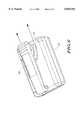
- FIG. 1shows a perspective view of a housing assembly 100 including a housing and an elongated mounting clip 120 constructed according to the present invention.
- the housingcomprises front and back covers 102, 104.
- the back cover 104includes a raised ridge 108 that is contiguous with the back cover 104, and that has under cut side walls 115, 117 forming a tapered recess 114 open at one end.
- the back cover 104includes a latch 106 coupled thereto.
- the latch 106is centered about the under cut side walls 115, 117 and has a detent 110 at an end opposite to the raised ridge 108 for interlocking the elongated mounting clip 120 to the back cover 104.
- the latch 106includes a recess 112 for depression of the latch 106 to assist in removing the elongated mounting clip 120 from the back cover 104.
- the elongated mounting clip 120is coupled to a base plate 118 that is contiguous therewith.
- the base plate 118is dimensioned for insertion within the under cut side walls 115, 117 of the raised ridge 108 for engagement with the detent 110 for latching the elongated mounting clip 120 to the back cover 104.
- the base plate 118includes beveled edges 116 for inserting within the under cut side walls 115, 117 and a guide channel 119 to guide the base plate 118 with the latch 106 during insertion.
- FIGS. 2 and 3show a cross-sectional and perspective view 103, respectively, of the housing after it has been assembled according to the present invention.
- the detent 110 of the latch 106interlocks the base plate 118 with the raised ridge 108 of the back cover 104.
- the recess 112is depressed while simultaneously pulling the elongated mounting clip 120 away from the raised ridge 108 (as indicated by the directional arrows).
- FIG. 4shows an alternative embodiment of the assembly of the elongated mounting clip 120 and the base plate 118 according to the present invention.
- the elongated mounting clip 120 and the base plate 118are coupled to a pivoting mechanism.
- the pivoting mechanismcomprises a plurality of upstanding projections 126 on the base plate 118 with a central opening 127 therein, a corresponding plurality of upstanding projections 124 on the elongated mounting clip 120 having similar openings 129 therein.
- the elongated mounting clip 120also includes an additional projection 124 and corresponding opening 129 at an edge opposite and parallel to the edge of the upstanding projection 124 shown.
- the locking mechanismincludes a lock pin 128 insertable in the openings 127, 129 of the projections 126, 124 of the base plate 118 and the elongated mounting clip 120, respectively. Additionally, a torsion spring 130 is mounted on the lock pin 128 to provide a set spring bias for the elongated mounting clip 120.
- the base plate 118is dimensioned for insertion within the under cut side walls 115, 117 of the raised ridge 108 for engagement with the detent 110 of the latch 106.
- FIG. 5shows a perspective view of the elongated mounting clip 120 and the base plate 118 after assembly with the pivoting mechanism, while FIG. 6 shows the same after assembly with the housing according to the present invention.
- the embodiments just describedare advantageous over the prior art.
- the raised ridge 108, and the latch 106are contiguous portions of the back cover 104.
- the base plate 118is contiguous with the elongated mounting clip 120. Consequently, only two assembly parts are necessary for assembly of the housing, thereby providing ease of manufacturability, which in turn reduces cost to the end consumer.
- removal of the elongated mounting clip 120 from the back cover 104is made easy, thereby improving serviceability of the housing assembly 100.
- the number of extra componentsis minimal.
- the interlocking strategy between the base plate 118 and the raised ridge 108 of the back cover 104is essentially the same, thereby maintaining the benefits of the first embodiment.
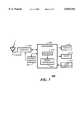
- FIG. 7shows an electrical block diagram of a SCR (selective call receiver) 200 included in the housing of FIG. 1 according to the present invention.
- the SCR 200comprises an antenna 202 for intercepting RF signals from, for example, a radio communication system (not shown).
- the antenna 202is coupled to a receiver 204 employing conventional demodulation techniques for receiving the communication signals transmitted by the radio communication system.
- Radio signals received by the receiver 204produce demodulated information, which is coupled to a processor 208 for processing received messages.
- a conventional power switch 206coupled to the processor 208, is used to control the supply of power to the receiver 204, thereby providing a battery saving function.
- the processor 208includes a microprocessor 212, and a memory 210 including a random access memory (RAM), a read-only memory (ROM), and an electrically erasable programmable read-only memory (EEPROM).
- RAMrandom access memory
- ROMread-only memory
- EEPROMelectrically erasable programmable read-only memory
- the processor 208is similar to the M68HC08 micro-controller manufactured by Motorola, Inc. It will be appreciated that other similar processors can be utilized for the processor 208, and that additional processors of the same or alternative type can be added as required to handle the processing requirements of the processor 208.
- the processor 208is programmed by way of the ROM to process incoming messages transmitted by the radio communication system.
- the processor 208decodes an address in the demodulated data of the received message, compares the decoded address with one or more addresses stored in the EEPROM, and when a match is detected, proceeds to process the remaining portion of the message.
- the processor 208stores the message in the RAM, and a call alerting signal is generated to alert a user that a message has been received.
- the call alerting signalis directed to a conventional audible or tactile alerting device 216 for generating an audible or tactile call alerting signal.
- the messagecan be accessed by the user through user controls 214, which provide functions such as lock, unlock, delete, read, etc. More specifically, by the use of appropriate functions provided by the user controls 214, the message is recovered from the RAM, and conveyed to the user by way of a display 218, e.g., a conventional liquid crystal display (LCD). It will be appreciated that, alternatively, the display 218 can be accompanied by an audio circuit (not shown) for conveying voice messages.
- LCDliquid crystal display
- the display 218can be accompanied by an audio circuit (not shown) for conveying voice messages.
Landscapes
- Engineering & Computer Science (AREA)
- Physics & Mathematics (AREA)
- Signal Processing (AREA)
- Computer Networks & Wireless Communication (AREA)
- Electromagnetism (AREA)
- General Physics & Mathematics (AREA)
- Mobile Radio Communication Systems (AREA)
Abstract
Description
This invention relates in general to a housing assembly, and particularly, to a housing assembly with a detachable mounting clip and a selective call receiver therein.
Numerous PCD's (portable communication devices) use a mounting clip as an accessory for allowing consumers to attach the PCD to his or her clothing attire (e.g., a belt). As with many consumer products, ease of manufacturability and serviceability of PCD's have a direct correlation on cost. An important aspect of manufacturability is the ease of assembly of the mounting clip to the housing of a PCD. The more components needed for assembly of the mounting clip to the housing (e.g., screws, spring, etc.) the slower the manufacturing process and the more likely that manufacturing defects will occur.
Although mounting clips are well known, they have not been entirely satisfactory. In some cases, mounting clips have been objectionably large requiring a number of parts resulting in excess manufacturing costs and complexity in assembly. Accordingly, what is needed is a housing assembly of a PCD that overcomes the foregoing disadvantages described in the prior art.
The present invention is pointed out with particularity in the appended claims. However, other features of the invention will become more apparent and best understood by referring to the following detailed description in conjunction with the accompanying drawings in which:
FIG. 1 shows a perspective view of a housing assembly including a housing and an elongated mounting clip constructed according to the present invention;
FIGS. 2 and 3 show a cross-sectional and perspective view, respectively, of the housing after it has been assembled according to the present invention;
FIG. 4 shows an assembly of the elongated mounting clip and a base plate coupled to a pivoting mechanism according to the present invention;
FIG. 5 shows a perspective view of the elongated mounting clip and the base plate after assembly with the pivoting mechanism, while FIG. 6 shows assembly of the same with the housing according to the present invention; and
FIG. 7 shows an electrical block diagram of a selective call receiver included in the housing of FIG. 1 according to the present invention.
FIG. 1 shows a perspective view of ahousing assembly 100 including a housing and anelongated mounting clip 120 constructed according to the present invention. The housing comprises front andback covers back cover 104 includes a raisedridge 108 that is contiguous with theback cover 104, and that has undercut side walls tapered recess 114 open at one end. Additionally, theback cover 104 includes alatch 106 coupled thereto. Thelatch 106 is centered about the under cutside walls ridge 108 for interlocking theelongated mounting clip 120 to theback cover 104. At an edge of the detent 110, thelatch 106 includes arecess 112 for depression of thelatch 106 to assist in removing theelongated mounting clip 120 from theback cover 104.
In a first embodiment, theelongated mounting clip 120 is coupled to abase plate 118 that is contiguous therewith. Thebase plate 118 is dimensioned for insertion within the undercut side walls ridge 108 for engagement with the detent 110 for latching theelongated mounting clip 120 to theback cover 104. Additionally, thebase plate 118 includesbeveled edges 116 for inserting within the undercut side walls guide channel 119 to guide thebase plate 118 with thelatch 106 during insertion. FIGS. 2 and 3 show a cross-sectional andperspective view 103, respectively, of the housing after it has been assembled according to the present invention. As should be evident from thecross-sectional view 103, once thelatch 106 has engaged with thebase plate 118, the detent 110 of thelatch 106 interlocks thebase plate 118 with the raisedridge 108 of theback cover 104. To remove theelongated mounting clip 120 from theback cover 104, therecess 112 is depressed while simultaneously pulling theelongated mounting clip 120 away from the raised ridge 108 (as indicated by the directional arrows).
FIG. 4 shows an alternative embodiment of the assembly of theelongated mounting clip 120 and thebase plate 118 according to the present invention. Under this embodiment, theelongated mounting clip 120 and thebase plate 118 are coupled to a pivoting mechanism. The pivoting mechanism comprises a plurality ofupstanding projections 126 on thebase plate 118 with acentral opening 127 therein, a corresponding plurality ofupstanding projections 124 on theelongated mounting clip 120 havingsimilar openings 129 therein. Although not shown, theelongated mounting clip 120 also includes anadditional projection 124 andcorresponding opening 129 at an edge opposite and parallel to the edge of theupstanding projection 124 shown. The locking mechanism includes alock pin 128 insertable in theopenings projections base plate 118 and theelongated mounting clip 120, respectively. Additionally, atorsion spring 130 is mounted on thelock pin 128 to provide a set spring bias for theelongated mounting clip 120.
As in the first embodiment, thebase plate 118 is dimensioned for insertion within the undercut side walls ridge 108 for engagement with the detent 110 of thelatch 106. FIG. 5 shows a perspective view of theelongated mounting clip 120 and thebase plate 118 after assembly with the pivoting mechanism, while FIG. 6 shows the same after assembly with the housing according to the present invention.
In many respects the embodiments just described are advantageous over the prior art. For example, in the first embodiment theraised ridge 108, and thelatch 106 are contiguous portions of theback cover 104. Similarly, thebase plate 118 is contiguous with theelongated mounting clip 120. Consequently, only two assembly parts are necessary for assembly of the housing, thereby providing ease of manufacturability, which in turn reduces cost to the end consumer. Additionally, with the addition of therecess 112 to thelatch 106, removal of theelongated mounting clip 120 from theback cover 104 is made easy, thereby improving serviceability of thehousing assembly 100. Although more parts are necessary in the second embodiment of theelongated mounting clip 120 and thebase plate 118, the number of extra components is minimal. More importantly, the interlocking strategy between thebase plate 118 and theraised ridge 108 of theback cover 104 is essentially the same, thereby maintaining the benefits of the first embodiment.
FIG. 7 shows an electrical block diagram of a SCR (selective call receiver) 200 included in the housing of FIG. 1 according to the present invention. TheSCR 200 comprises anantenna 202 for intercepting RF signals from, for example, a radio communication system (not shown). Theantenna 202 is coupled to areceiver 204 employing conventional demodulation techniques for receiving the communication signals transmitted by the radio communication system. Radio signals received by thereceiver 204 produce demodulated information, which is coupled to aprocessor 208 for processing received messages. Aconventional power switch 206, coupled to theprocessor 208, is used to control the supply of power to thereceiver 204, thereby providing a battery saving function.
To perform the necessary functions of theSCR 200, theprocessor 208 includes amicroprocessor 212, and amemory 210 including a random access memory (RAM), a read-only memory (ROM), and an electrically erasable programmable read-only memory (EEPROM). Preferably, theprocessor 208 is similar to the M68HC08 micro-controller manufactured by Motorola, Inc. It will be appreciated that other similar processors can be utilized for theprocessor 208, and that additional processors of the same or alternative type can be added as required to handle the processing requirements of theprocessor 208.
Theprocessor 208 is programmed by way of the ROM to process incoming messages transmitted by the radio communication system. Theprocessor 208 decodes an address in the demodulated data of the received message, compares the decoded address with one or more addresses stored in the EEPROM, and when a match is detected, proceeds to process the remaining portion of the message. Once theprocessor 208 has processed the message, it stores the message in the RAM, and a call alerting signal is generated to alert a user that a message has been received. The call alerting signal is directed to a conventional audible or tactilealerting device 216 for generating an audible or tactile call alerting signal.
The message can be accessed by the user throughuser controls 214, which provide functions such as lock, unlock, delete, read, etc. More specifically, by the use of appropriate functions provided by theuser controls 214, the message is recovered from the RAM, and conveyed to the user by way of adisplay 218, e.g., a conventional liquid crystal display (LCD). It will be appreciated that, alternatively, thedisplay 218 can be accompanied by an audio circuit (not shown) for conveying voice messages.
Although the invention has been described in terms of a preferred embodiment it will be obvious to those skilled in the art that many alterations and variations may be made without departing from the invention. Accordingly, it is intended that all such alterations and variations be considered as within the spirit and scope of the invention as defined by the appended claims.
Claims (8)
1. A housing assembly, comprising:
a housing;
a raised ridge contiguous with the housing, the raised ridge having under cut side walls forming a tapered recess open at one end;
a latch contiguous with the housing, the latch centered about the under cut side walls and having a detent at an end opposite to the raised ridge;
an elongated mounting clip; and
a base plate contiguous with the elongated mounting clip,
wherein the base plate further comprises beveled edges for inserting within the under cut side walls, and a guide channel to guide the base plate with the latch during insertion, and
wherein the base plate is dimensioned to insert within the under cut side walls of the raised ridge and to engage with the detent for latching the elongated mounting clip to the housing.
2. The housing assembly as recited in claim 1, wherein the latch further includes a recess at an edge of the detent for depression of the latch to assist in removing the elongated mounting clip from the housing.
3. The housing assembly as recited in claim 1, wherein the elongated mounting clip and the base plate are coupled to a pivoting mechanism.
4. The housing assembly as recited in claim 3, wherein the pivoting mechanism comprises:
a plurality of upstanding projections on the base plate with a central opening therein;
a corresponding plurality of upstanding projections on the elongated mounting clip having similar openings therein; and
a lock pin insertable in the opening of the projections of the base plate and the elongated mounting clip.
5. The housing assembly as recited in claim 4, wherein the pivoting mechanism further comprises a torsion spring mounted on the lock pin to provide a set spring bias for the elongated mounting clip.
6. The housing assembly as recited in claim 1, wherein the housing comprises a selective call receiver.
7. A housing assembly, comprising:
a housing;
a raised ridge coupled to the housing, the raised ridge having under cut side walls forming a tapered recess open at one end;
a latch coupled to the housing, the latch centered about the under cut side walls and having a detent at an end opposite to the raised ridge;
an elongated mounting clip;
a base plate coupled to the elongated mounting clip, the base plate dimensioned to insert within the under cut side walls of the raised ridge and to engage with the detent for latching the elongated mounting clip to the housing; and
a pivoting mechanism coupled to the base plate and the elongated mounting clip, wherein the pivoting mechanism comprises:
a plurality of upstanding projections on the base plate with a central opening therein,
a corresponding plurality of upstanding projections on the elongated mounting clip having similar openings therein,
a lock pin insertable in the opening of the projections of the base plate and the elongated mounting clip, and
a torsion spring mounted on the lock pin to provide a set spring bias for the elongated mounting clip.
8. The housing assembly as recited in claim 7, wherein the housing comprises a selective call receiver.
Priority Applications (1)
| Application Number | Priority Date | Filing Date | Title |
|---|---|---|---|
| US08/954,114US5829102A (en) | 1997-10-20 | 1997-10-20 | Housing assembly with a detachable mounting clip and a selective call receiver therein |
Applications Claiming Priority (1)
| Application Number | Priority Date | Filing Date | Title |
|---|---|---|---|
| US08/954,114US5829102A (en) | 1997-10-20 | 1997-10-20 | Housing assembly with a detachable mounting clip and a selective call receiver therein |
Publications (1)
| Publication Number | Publication Date |
|---|---|
| US5829102Atrue US5829102A (en) | 1998-11-03 |
Family
ID=25494946
Family Applications (1)
| Application Number | Title | Priority Date | Filing Date |
|---|---|---|---|
| US08/954,114Expired - LifetimeUS5829102A (en) | 1997-10-20 | 1997-10-20 | Housing assembly with a detachable mounting clip and a selective call receiver therein |
Country Status (1)
| Country | Link |
|---|---|
| US (1) | US5829102A (en) |
Cited By (29)
| Publication number | Priority date | Publication date | Assignee | Title |
|---|---|---|---|---|
| US6073318A (en)* | 1999-05-04 | 2000-06-13 | Research In Motion Limited | Retaining clip assembly |
| US6149043A (en)* | 1997-08-27 | 2000-11-21 | Nec Corporation | Holder for electronic device |
| WO2001043576A1 (en)* | 1999-12-14 | 2001-06-21 | Ilife Systems, Inc. | Belt clip with improved flange |
| US6252555B1 (en) | 1999-12-23 | 2001-06-26 | John E. Burton | Antenna clip for electronic components |
| US6253420B1 (en)* | 1997-08-20 | 2001-07-03 | Ericsson Radio Systems B.V. | Clamping assembly |
| US6311881B1 (en)* | 1998-07-07 | 2001-11-06 | Nec Corporation | Holder for a portable apparatus |
| US6405910B1 (en)* | 2000-11-06 | 2002-06-18 | Research In Motion Limited | Removable retaining clip assembly |
| US6550655B2 (en)* | 1999-03-31 | 2003-04-22 | Shirley Warner | Securing device for personal pagers |
| EP1306645A1 (en)* | 2001-10-24 | 2003-05-02 | Tajima Tool Corporation | Holder assembly for hand-held device |
| US6607327B1 (en)* | 2002-02-06 | 2003-08-19 | Kuo-Ping Ho | Fastening device for the backseat of a bicycle |
| WO2003051178A3 (en)* | 2001-12-14 | 2004-04-22 | Medtronic Minimed Inc | Low-profile mounting clip for personal device |
| US20040134945A1 (en)* | 2002-11-06 | 2004-07-15 | Robert Kincaid | Throat height adjustment in a belt loop or belt clip |
| US20040149797A1 (en)* | 2003-01-24 | 2004-08-05 | Hotronic International Ltd | Battery pack retention system |
| US20040192419A1 (en)* | 2002-06-03 | 2004-09-30 | Accton Technology | Multi-function clip structure for a wireless adapter |
| US20050271231A1 (en)* | 2004-06-07 | 2005-12-08 | Caploon Konstantin A | Audio recordation and reproduction spring clips |
| US20060283898A1 (en)* | 2005-06-20 | 2006-12-21 | A.G. Findings & Mfg. Co., Inc | All plastic belt or strap clip for cell phones and personal electronic devices |
| US20070241149A1 (en)* | 2004-01-09 | 2007-10-18 | Dilip Bhavnani | Handheld device cradle with a substantially semicircular clip assembly and an advertising method |
| US20070267250A1 (en)* | 2006-05-19 | 2007-11-22 | Wolff Richard J | Electric human lift |
| US20080066358A1 (en)* | 2004-01-09 | 2008-03-20 | Dilip Bhavnani | handheld electronic device with a substantially semicircular spring clip assembly and an advertising method |
| US20090026242A1 (en)* | 2007-07-27 | 2009-01-29 | Pagecomm International Inc. | Personal communications device case connector system |
| US20090144943A1 (en)* | 2007-12-11 | 2009-06-11 | Manuel Arranz Del Rosal | Interchangeable electronic device clip |
| US20100154269A1 (en)* | 2009-04-07 | 2010-06-24 | Escalante Iii Manuel | Gun magazine with clip |
| US20100229348A1 (en)* | 2009-03-16 | 2010-09-16 | Meredith Pike | Ring Cling |
| US8180410B2 (en) | 2008-06-06 | 2012-05-15 | Sandisk Technologies Inc. | Housing and clip assembly for portable electronics device |
| EP2490412A1 (en)* | 2011-02-18 | 2012-08-22 | Gigaset Communications GmbH | Clip fixing to prevent loss |
| US10820683B1 (en)* | 2019-07-30 | 2020-11-03 | Motorola Solutions, Inc. | Holster with attachment interface |
| USD934206S1 (en)* | 2020-12-08 | 2021-10-26 | Baoping Liu | Wireless microphone |
| USD953304S1 (en)* | 2020-08-12 | 2022-05-31 | Shenzhen Lynca Photographic Equipment Co., Ltd | Wireless microphone |
| US20240207746A1 (en)* | 2022-11-25 | 2024-06-27 | Mi Hiepa Scout Limited | Apparatus for mounting a controller to a user |
Citations (5)
| Publication number | Priority date | Publication date | Assignee | Title |
|---|---|---|---|---|
| US4083481A (en)* | 1977-03-10 | 1978-04-11 | Motorola, Inc. | Detachable mounting clip arrangement for miniature portable apparatus or the like |
| US4741074A (en)* | 1987-01-07 | 1988-05-03 | Motorola, Inc. | Detachable belt clip suitable for automated assembly |
| US4956895A (en)* | 1986-12-25 | 1990-09-18 | Nec Corporation | Removable clip for portable equipment |
| US5488759A (en)* | 1994-07-28 | 1996-02-06 | Motorola, Inc. | Detachable clip for a portable electronic device |
| US5664292A (en)* | 1996-08-22 | 1997-09-09 | E Lead Electronic Co., Ltd. | Separable clip assembly |
- 1997
- 1997-10-20USUS08/954,114patent/US5829102A/ennot_activeExpired - Lifetime
Patent Citations (5)
| Publication number | Priority date | Publication date | Assignee | Title |
|---|---|---|---|---|
| US4083481A (en)* | 1977-03-10 | 1978-04-11 | Motorola, Inc. | Detachable mounting clip arrangement for miniature portable apparatus or the like |
| US4956895A (en)* | 1986-12-25 | 1990-09-18 | Nec Corporation | Removable clip for portable equipment |
| US4741074A (en)* | 1987-01-07 | 1988-05-03 | Motorola, Inc. | Detachable belt clip suitable for automated assembly |
| US5488759A (en)* | 1994-07-28 | 1996-02-06 | Motorola, Inc. | Detachable clip for a portable electronic device |
| US5664292A (en)* | 1996-08-22 | 1997-09-09 | E Lead Electronic Co., Ltd. | Separable clip assembly |
Cited By (37)
| Publication number | Priority date | Publication date | Assignee | Title |
|---|---|---|---|---|
| US6253420B1 (en)* | 1997-08-20 | 2001-07-03 | Ericsson Radio Systems B.V. | Clamping assembly |
| US6149043A (en)* | 1997-08-27 | 2000-11-21 | Nec Corporation | Holder for electronic device |
| US6311881B1 (en)* | 1998-07-07 | 2001-11-06 | Nec Corporation | Holder for a portable apparatus |
| US6443343B2 (en)* | 1998-07-07 | 2002-09-03 | Nec Corporation | Holder for a portable apparatus |
| US6550655B2 (en)* | 1999-03-31 | 2003-04-22 | Shirley Warner | Securing device for personal pagers |
| US6073318A (en)* | 1999-05-04 | 2000-06-13 | Research In Motion Limited | Retaining clip assembly |
| WO2001043576A1 (en)* | 1999-12-14 | 2001-06-21 | Ilife Systems, Inc. | Belt clip with improved flange |
| US6321418B1 (en)* | 1999-12-14 | 2001-11-27 | Ilife Ssytems, Inc. | Belt clip with improved flange |
| US6252555B1 (en) | 1999-12-23 | 2001-06-26 | John E. Burton | Antenna clip for electronic components |
| US6405910B1 (en)* | 2000-11-06 | 2002-06-18 | Research In Motion Limited | Removable retaining clip assembly |
| EP1306645A1 (en)* | 2001-10-24 | 2003-05-02 | Tajima Tool Corporation | Holder assembly for hand-held device |
| US6824028B2 (en) | 2001-10-24 | 2004-11-30 | Tajima Tool Corporation | Holder assembly for hand-held device |
| WO2003051178A3 (en)* | 2001-12-14 | 2004-04-22 | Medtronic Minimed Inc | Low-profile mounting clip for personal device |
| US6607327B1 (en)* | 2002-02-06 | 2003-08-19 | Kuo-Ping Ho | Fastening device for the backseat of a bicycle |
| US20040192419A1 (en)* | 2002-06-03 | 2004-09-30 | Accton Technology | Multi-function clip structure for a wireless adapter |
| US6902431B2 (en)* | 2002-06-03 | 2005-06-07 | Accton Technology Corporation | Multi-function clip structure for a wireless adapter |
| US20040134945A1 (en)* | 2002-11-06 | 2004-07-15 | Robert Kincaid | Throat height adjustment in a belt loop or belt clip |
| US20040149797A1 (en)* | 2003-01-24 | 2004-08-05 | Hotronic International Ltd | Battery pack retention system |
| US20070241149A1 (en)* | 2004-01-09 | 2007-10-18 | Dilip Bhavnani | Handheld device cradle with a substantially semicircular clip assembly and an advertising method |
| US20080066358A1 (en)* | 2004-01-09 | 2008-03-20 | Dilip Bhavnani | handheld electronic device with a substantially semicircular spring clip assembly and an advertising method |
| US20050271231A1 (en)* | 2004-06-07 | 2005-12-08 | Caploon Konstantin A | Audio recordation and reproduction spring clips |
| US8050429B2 (en) | 2004-06-07 | 2011-11-01 | Caploon Konstantin A | Audio recordation and reproduction spring clips |
| US7577264B2 (en)* | 2004-06-07 | 2009-08-18 | Konstantin A. Caploon | Audio recordation and reproduction spring clips |
| US20060283898A1 (en)* | 2005-06-20 | 2006-12-21 | A.G. Findings & Mfg. Co., Inc | All plastic belt or strap clip for cell phones and personal electronic devices |
| US7980435B2 (en)* | 2005-06-20 | 2011-07-19 | A.G. Findings & Manufacturing Company, Inc. | All plastic belt or strap clip for cell phones and personal electronic devices |
| US20070267250A1 (en)* | 2006-05-19 | 2007-11-22 | Wolff Richard J | Electric human lift |
| US20090026242A1 (en)* | 2007-07-27 | 2009-01-29 | Pagecomm International Inc. | Personal communications device case connector system |
| US20090144943A1 (en)* | 2007-12-11 | 2009-06-11 | Manuel Arranz Del Rosal | Interchangeable electronic device clip |
| US8180410B2 (en) | 2008-06-06 | 2012-05-15 | Sandisk Technologies Inc. | Housing and clip assembly for portable electronics device |
| US8353086B2 (en)* | 2009-03-16 | 2013-01-15 | Meredith Pike | Ring cling |
| US20100229348A1 (en)* | 2009-03-16 | 2010-09-16 | Meredith Pike | Ring Cling |
| US20100154269A1 (en)* | 2009-04-07 | 2010-06-24 | Escalante Iii Manuel | Gun magazine with clip |
| EP2490412A1 (en)* | 2011-02-18 | 2012-08-22 | Gigaset Communications GmbH | Clip fixing to prevent loss |
| US10820683B1 (en)* | 2019-07-30 | 2020-11-03 | Motorola Solutions, Inc. | Holster with attachment interface |
| USD953304S1 (en)* | 2020-08-12 | 2022-05-31 | Shenzhen Lynca Photographic Equipment Co., Ltd | Wireless microphone |
| USD934206S1 (en)* | 2020-12-08 | 2021-10-26 | Baoping Liu | Wireless microphone |
| US20240207746A1 (en)* | 2022-11-25 | 2024-06-27 | Mi Hiepa Scout Limited | Apparatus for mounting a controller to a user |
Similar Documents
| Publication | Publication Date | Title |
|---|---|---|
| US5829102A (en) | Housing assembly with a detachable mounting clip and a selective call receiver therein | |
| US5931513A (en) | Housing assembly including a latch mechanism and a selective call receiver | |
| US5361061A (en) | Computer card data receiver having a foldable antenna | |
| US6176401B1 (en) | Holster for a portable communication device | |
| US5832388A (en) | Portable radiotelephone device adapted to receive a variety of other portable devices | |
| US6115616A (en) | Hand held telephone set with separable keyboard | |
| US5818701A (en) | Portable telephone having a reversible and sliding card casing | |
| US6600662B1 (en) | Light guide for a foldable electronic device | |
| US6006074A (en) | Apparatus having different shielding covers | |
| US6049725A (en) | Charging cradle | |
| JP3056080B2 (en) | Mobile phone | |
| JPH11317610A (en) | Dual mode antenna for foldable mobile telephone set | |
| MY112834A (en) | Sim card connector | |
| US5883786A (en) | SIM card containment assembly for an electronic apparatus | |
| US6212366B1 (en) | Housing assembly for a selective call receiver | |
| US5346784A (en) | Electronic device having an integral battery door/belt clip element | |
| GB2307579A (en) | Radio selection call receiver | |
| US6527189B2 (en) | Card reader connector with removable extension bracket | |
| WO1990013951A1 (en) | Thin articulated pager | |
| JP2701691B2 (en) | Wireless receiver | |
| US6166621A (en) | Method and apparatus for displaying a message which has been received | |
| KR920017390A (en) | Wireless pager | |
| JP2701750B2 (en) | Foldable electronic device with display function | |
| EP0643361B2 (en) | Electric terminal with memory card reader | |
| JP3280859B2 (en) | Portable equipment |
Legal Events
| Date | Code | Title | Description |
|---|---|---|---|
| AS | Assignment | Owner name:MOTOROLA, INC., ILLINOIS Free format text:ASSIGNMENT OF ASSIGNORS INTEREST;ASSIGNOR:CONTI, BRIAN V.;REEL/FRAME:008787/0315 Effective date:19971016 | |
| STCF | Information on status: patent grant | Free format text:PATENTED CASE | |
| FEPP | Fee payment procedure | Free format text:PAYOR NUMBER ASSIGNED (ORIGINAL EVENT CODE: ASPN); ENTITY STATUS OF PATENT OWNER: LARGE ENTITY | |
| FPAY | Fee payment | Year of fee payment:4 | |
| FPAY | Fee payment | Year of fee payment:8 | |
| FPAY | Fee payment | Year of fee payment:12 | |
| AS | Assignment | Owner name:MOTOROLA SOLUTIONS, INC., ILLINOIS Free format text:CHANGE OF NAME;ASSIGNOR:MOTOROLA, INC;REEL/FRAME:026081/0001 Effective date:20110104 |