US5828984A - Data processing method for an electronic compass system - Google Patents
Data processing method for an electronic compass systemDownload PDFInfo
- Publication number
- US5828984A US5828984AUS08/131,014US13101493AUS5828984AUS 5828984 AUS5828984 AUS 5828984AUS 13101493 AUS13101493 AUS 13101493AUS 5828984 AUS5828984 AUS 5828984A
- Authority
- US
- United States
- Prior art keywords
- heading data
- distorted
- transformed
- calibration
- processor
- Prior art date
- Legal status (The legal status is an assumption and is not a legal conclusion. Google has not performed a legal analysis and makes no representation as to the accuracy of the status listed.)
- Expired - Lifetime
Links
Images


Classifications
- G—PHYSICS
- G01—MEASURING; TESTING
- G01C—MEASURING DISTANCES, LEVELS OR BEARINGS; SURVEYING; NAVIGATION; GYROSCOPIC INSTRUMENTS; PHOTOGRAMMETRY OR VIDEOGRAMMETRY
- G01C17/00—Compasses; Devices for ascertaining true or magnetic north for navigation or surveying purposes
- G01C17/38—Testing, calibrating, or compensating of compasses
Definitions
- the present inventionrelates to electronic compasses and more specifically a method of processing data in an electronic compass system using linear transforms.
- Ferrous metalsact as conduits for magnetic fields, focusing them in some places and directions, and rarefying them in others.
- Magnetic distortionsare of two types, rotations and elliptifications. Rotations are evidenced by an angular deviation between actual magnetic north and the magnetic north sensed by the flux gate sensor. Elliptifications result when magnetic fields are amplified or attenuated along different axes, thereby increasing the field strength sensed by one coil of the flux-gate sensor and decreasing the field strength sensed by the other coil.
- An object of the present inventionis to use linear transforms to offset rotation and elliptification in electronic compass readings and to produce a circle in the transformed coordinates, called the earth's field circle, whose orientation is referenced to actual magnetic north.
- a method for processing data in an electronic compass system using linear transformsis provided.
- a linear transform for converting distorted compass data values into undistorted data valuesis formulated.
- the linear transformis programmed into the read only memory of the microcomputer of the electronic compass system.
- the microcomputeruses the linear transform to transform distorted compass data readings into corrected data readings and then uses the corrected data readings to compute headings.
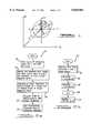
- FIG. 1contains an ellipse and a circle referenced to a Cartesian coordinate system.
- the ellipseis generated by a vector E, which represents the magnitude and direction of the earth's magnetic field as sensed by the flux gate sensor.
- the circleis generated by a vector R which represents the actual magnitude and direction of the earth's magnetic field;
- FIG. 1aillustrates a normal circle
- FIG. 1billustrates an example of rotational distortion
- FIG. 1c and 1dillustrate examples of elliptification distortion
- FIGS. 2a and 2bare flowcharts which help illustrate the method of the present invention.
- FIG. 3is a block diagram of the electronic compass system of the '843 patent to Hormel.
- FIG. 1there is shown a Cartesian coordinate system referenced to a frame of reference of a vehicle in which an electronic compass system is installed.
- the vector Vis the vehicle's magnetic field vector. This vector remains constant in magnitude and direction.
- the earth's magnetic field circle 6is the locus of points described by the earth's magnetic field vector R as the vehicle changes heading.
- an ellipse 8representing a distorted earth's field circle 6. Distortion is produced by ferrous metals within the vehicle.
- a non-distorted representation of the earth's magnetic field circle 6is shown in FIG. 1a.
- Rotationis also shown in FIG. 1b.
- Rotationis the angular deviation between the actual direction of the earth's magnetic field and the direction of the earth's magnetic field as sensed by the flux gate sensor. This angular deviation is represented by the angle ⁇ .
- Rotationoccurs when the earth's magnetic field lines change direction in order to flow through the vehicle.
- the ferrous metals within the vehiclepresent a low-resistance path to magnetic field lines when the vehicle is not saturated.
- Elliptificationis the deviation in magnitude between the actual strength of the earth's magnetic field and the strength of the earth's magnetic field as sensed by the flux gate sensor. Elliptification is illustrated by the vector E. Elliptification is also shown in FIGS. 1c and 1d.
- the magnitude of the vector Eis greater than the magnitude of vector R, the earth's magnetic field is being amplified by the vehicle.
- the magnitude of vector Eis less than the magnitude of the vector R, then the earth's magnetic field is being attenuated by the vehicle. Amplification and attenuation depend upon the orientation of the earth's magnetic field with respect to the vehicle.
- the present inventionemploys linear transforms to offset the effects of rotation and elliptification upon the heading solution generated by a microcomputer of an electronic compass system.
- Linear transformsare appropriate because the earth's magnetic field is incapable of saturating the flux path through the vehicle. After a linear transform has been used to convert an ellipse into the earth's field circle, the center of the circle can be calculated in the transformed coordinates in a consistent and reliable manner, such as the method disclosed in the '462 patent to Al-Attar.
- the earth's magnetic fieldis distorted by the vehicle by the time it reaches the flux gate sensor. If the corrected field has two components, X and Y, referenced to the x-y coordinate system, then the distorted field has the components F(X) and F(Y) where vector F is a distortion operator. Since the metal of the vehicle is not saturated by the earth's magnetic field, the distortion effects are linear. Therefore,
- Gis the operator which will convert the distorted readings sensed by the flux gate sensor into a properly oriented circle.
- x, y, f i (X+Y), f j (X+Y)equal the magnitudes of X, Y, F i (X+Y), and F j (X+Y), respectively, and 1 and j are unit vectors. Therefore, once a, b, c and d are determined, x and y can be determined by only four multiplications and two additions using the following equations: ##EQU1## The microcomputer then uses the x and y data values to determine headings.
- ris the radius of the earth's field circle.
- a value for rcan be obtained by approximation and averaging over previously obtained values.
- One way to estimate ris to average the semi-major and semi-minor axes, A and B, of the ellipse in accordance with the formula:
- the radius of the circle output from the transformis somewhat arbitrary; the constants in the transform can be multiplied by most any value and the output will still be a circle.
- the multiplieris chosen to make the calculations simpler without adverse effects on the calibration procedure (which is sensitive to the circle radius).
- the digital data values making up the ellipsemust be converted to values in the i-j coordinate system.
- This translation of data values from one coordinate system to anotheris achieved by moving the center of the ellipse (X de , Y de ), which forms the origin 0 of the i-j coordinate system, to the origin 0 d of the digital or x d -y d coordinate system.
- the translation formulasbecome:
- the i-j coordinate systemcould have been oriented such that the j axis would be aligned with the vector E; however, this orientation would have required both a rotation and a translation to convert the values of the x d -y d coordinate system to values in the i-j coordinate system.
- FIGS. 2(a) and 2(b)summarize the method 10 above.
- compass datais collected for a full 360° and plotted. This data is referenced to the x d -y d coordinate system.
- block 30measurements of the semi-major and semi-minor axes, a and b shown in FIG. 1, and the data points (x cd'N , y dN ), (x dE' , y dE ), and (x de , y de ) are obtained.
- these measurementsare used to formulate a linear transform, which in block 50 is programmed into the ROM of the microcomputer.
- the microcomputertransforms the distorted data values in the x d -y d coordinate system to values in the x-y coordinate system before computing vehicle headings.
- the method of block 60is shown in more detail in FIG. 2(b).
- the microcomputermeasures and stores distorted data values in block 70.
- the microcomputercalculates the x coordinate which represents an undistorted and calibrated value.
- the microcomputerperforms a similar transformation in the distorted y coordinate in block 90. Heading calculations are performed in blocks 100 and 110 by dividing the calibrated and undistorted y value by the calibrated and undistorted x value and the arctangent of the quotient is taken using work-up-tables or a piece-wise-linear-function-of-x routine.
- FIG. 3there is shown a block diagram of an electronic compass system 200 capable of using the method of the present invention, the '843 patent to Hormel.
- the heart of the systemis the microcomputer 212 which employs an 8-bit analog-to-digital converter 214.
- the microcomputer 212controls operation of the electronic compass system 210, beginning with a flux-gate driver 216.
- the flux-gate driver 216adds enough drive to the signal to saturate the flux-gate 218.
- the operation of the flux-gate driver 216 and flux-gate 218are explained in the documents incorporated by reference, namely "A Magnetic Heading Reference for the Electro/Fluidic Autopilot” and “Magnetic Field Sensor and its Application to Automobiles, (SAE Paper No. 800123)".
- the flux-gateemploys two sense coils oriented perpendicularly to one another. Voltages are induced across the sensor coils by the presence of the magnetic fields of the vehicle and the earth.
- the voltages from the sense coils of the flux-gate 218are processed by the multiplexer 220.
- the multiplexer 220is in communication with the microcomputer 212, which generates a signal for controlling a network for switching use of the four-pole bandpass filter 222, the synchronous detector 224 and the integrator 226 periodically from one sense coil to the other.
- the multiplexer 220is in communication with the four-pole bandpass filter 222, which filters out all but the second harmonic signals, whose amplitude is proportional to the earth's magnetic field.
- Second harmonic signalsare presented to the synchronous detector 224.
- the function of the synchronous detector 224is to select the portion of the filtered signals to be integrated by the integrator 226.
- the output of the synchronous detector 224is a half-wave rectified signal which is fed into the integrator 226.
- the output of the integrator 226periodically switches back and forth between two DC levels corresponding to the two sense coils of the flux-gate 218. Integrator output is stabilized by feeding back a current through resistor R f to the sense coils of the flux-gate 218. The feedback current eventually becomes an equal and opposite signal versus that produced by the magnetic field sensed by the flux-gate 218. Heading information is determined from the output of the integrator 226.
- the microcomputer 212is coupled to the integrator output through the 8-bit analog-to-digital converter 214.
- the 8-bit analog-to-digital converter 214converts the DC levels to digital coordinates referenced to a Cartesian coordinate system.
- the microcomputer 212divides the y-coordinate, corresponding to the DC level from one coil, by the x-coordinate, corresponding to the other coil, and takes the arctangent of the quotient using a piece-wise-linear-function-of-x routine to yield the vehicle's heading.
Landscapes
- Engineering & Computer Science (AREA)
- Radar, Positioning & Navigation (AREA)
- Remote Sensing (AREA)
- Physics & Mathematics (AREA)
- General Physics & Mathematics (AREA)
- Measuring Magnetic Variables (AREA)
Abstract
Description
F(X+Y)-F(X)+F(Y) (1).
G(F(X))=X (2),
G(F(Y))=Y (3).
F.sub.i (X+Y)=F.sub.i (X)+F.sub.i (Y) (4),
F.sub.j (X+Y)=F.sub.j (X)+F.sub.j (Y) (5).
F.sub.i (X+Y)=f.sub.i (X+Y)1=ax1+by1 (6),
F.sub.j (X+Y)=f.sub.j (X+Y)j=cxj+dyj (7).
f.sub.i (X+Y).sub.1 =ax.sub.1 +by.sub.1 (10),
f.sub.j (X+Y).sub.1 =cx.sub.1 +dy.sub.1 (11),
f.sub.i (X+Y).sub.2 =ax.sub.2 +by.sub.2 (12),
f.sub.j (X+Y).sub.2 =cx.sub.2 +dy.sub.2 (13).
a=f.sub.i (X+Y)E'/r (14),
b=f.sub.i (X+Y)N'/r (15),
c=f.sub.j (X+Y)E'/r (16),
d=f.sub.j (X+Y)N'/r (17).
r=0.5 (A+B) (18).
f.sub.i (X+Y)=x.sub.d -x.sub.de (19),
f.sub.i (X+Y)=y.sub.d -y.sub.de (20).
Claims (5)
Priority Applications (1)
| Application Number | Priority Date | Filing Date | Title |
|---|---|---|---|
| US08/131,014US5828984A (en) | 1991-12-27 | 1993-10-01 | Data processing method for an electronic compass system |
Applications Claiming Priority (2)
| Application Number | Priority Date | Filing Date | Title |
|---|---|---|---|
| US81526691A | 1991-12-27 | 1991-12-27 | |
| US08/131,014US5828984A (en) | 1991-12-27 | 1993-10-01 | Data processing method for an electronic compass system |
Related Parent Applications (1)
| Application Number | Title | Priority Date | Filing Date |
|---|---|---|---|
| US81526691AContinuation | 1991-12-27 | 1991-12-27 |
Publications (1)
| Publication Number | Publication Date |
|---|---|
| US5828984Atrue US5828984A (en) | 1998-10-27 |
Family
ID=25217331
Family Applications (1)
| Application Number | Title | Priority Date | Filing Date |
|---|---|---|---|
| US08/131,014Expired - LifetimeUS5828984A (en) | 1991-12-27 | 1993-10-01 | Data processing method for an electronic compass system |
Country Status (1)
| Country | Link |
|---|---|
| US (1) | US5828984A (en) |
Cited By (8)
| Publication number | Priority date | Publication date | Assignee | Title |
|---|---|---|---|---|
| US6301794B1 (en)* | 1999-05-27 | 2001-10-16 | Johnson Controls, Inc. | Vehicle compass system with continuous automatic calibration |
| US6539639B2 (en) | 2000-12-06 | 2003-04-01 | Honeywell International Inc. | Monitoring accuracy of an electronic compass |
| US6543146B2 (en) | 2000-12-06 | 2003-04-08 | Honeywell International, Inc. | Electronic compass and compensation of large magnetic errors for operation over all orientations |
| US20040111907A1 (en)* | 2002-12-11 | 2004-06-17 | Mitsubishi Denki Kabushiki Kaisha | Direction indicating device |
| US20050223573A1 (en)* | 2004-04-07 | 2005-10-13 | Siemens Vdo Automotive Corporation | Compass heading noise immunity |
| US20080071492A1 (en)* | 2006-09-20 | 2008-03-20 | Samsung Electronics Co., Ltd. | Method, apparatus, and medium for calibrating compass sensor in consideration of magnetic environment and method, apparatus, and medium for measuring azimuth using the compass sensor calibration method, apparatus, and medium |
| US20090254294A1 (en)* | 2008-03-06 | 2009-10-08 | Texas Instruments Incorporated | Processes for more accurately calibrating and operating e-compass for tilt error, circuits, and systems |
| JPWO2021214956A1 (en)* | 2020-04-23 | 2021-10-28 |
Citations (19)
| Publication number | Priority date | Publication date | Assignee | Title |
|---|---|---|---|---|
| US3899834A (en)* | 1972-10-02 | 1975-08-19 | Westinghouse Electric Corp | Electronic compass system |
| US3991361A (en)* | 1975-03-27 | 1976-11-09 | Westinghouse Electric Corporation | Semi-automatic compass calibrator apparatus for a vehicle mounted flux gate compass system to cancel out effect of local magnetic disturbances |
| GB2056686A (en)* | 1979-08-10 | 1981-03-18 | Sperry Corp | Flux valve compass system |
| US4414753A (en)* | 1980-06-05 | 1983-11-15 | Crouzet | Process for compensating the magnetic disturbances in the determination of a magnetic heading, and devices for carrying out this process |
| US4424631A (en)* | 1982-03-02 | 1984-01-10 | Prince Corporation | Electrical compass |
| US4425717A (en)* | 1982-06-24 | 1984-01-17 | Prince Corporation | Vehicle magnetic sensor |
| EP0120691A2 (en)* | 1983-03-24 | 1984-10-03 | Prince Corporation | Electrical compass |
| US4505054A (en)* | 1983-05-25 | 1985-03-19 | Prince Corporation | Magnetic sensor mounting system |
| JPS60135814A (en)* | 1983-12-26 | 1985-07-19 | Nec Corp | Azimuth detecting apparatus |
| US4622646A (en)* | 1982-09-08 | 1986-11-11 | The Commonwealth Of Australia Of C/-Department Of Defence Support | Arrangements for correcting compasses |
| US4660161A (en)* | 1983-06-17 | 1987-04-21 | Honda Giken Kogyo Kabushiki Kaisha | Correction method for vehicle-mounted geomagnetic field sensors |
| US4672565A (en)* | 1981-03-10 | 1987-06-09 | Nippon Soken, Inc. | Direction detecting system for vehicles |
| US4677381A (en)* | 1984-10-19 | 1987-06-30 | Prince Corporation | Flux-gate sensor electrical drive method and circuit |
| US4698912A (en)* | 1985-12-11 | 1987-10-13 | The Laitram Corporation | Magnetic compass calibration |
| US4797841A (en)* | 1983-11-28 | 1989-01-10 | Magnavox Government And Industrial Electronics Company | Method and apparatus for automatic calibration of magnetic compass |
| US4807462A (en)* | 1987-04-03 | 1989-02-28 | Chrysler Motors Corporation | Method for performing automatic calibrations in an electronic compass |
| US4831563A (en)* | 1986-07-01 | 1989-05-16 | Pioneer Electronic Corporation | Method of processing output data from geomagnetic sensor |
| US5046031A (en)* | 1989-02-06 | 1991-09-03 | Magnavox Government And Industrial Electronics Company | Method and apparatus for automatic flux-gate compass calibration |
| US5161311A (en)* | 1990-08-29 | 1992-11-10 | Alps Electric Inc. | Calibration and compensation of an electronic compass system |
- 1993
- 1993-10-01USUS08/131,014patent/US5828984A/ennot_activeExpired - Lifetime
Patent Citations (20)
| Publication number | Priority date | Publication date | Assignee | Title |
|---|---|---|---|---|
| US3899834A (en)* | 1972-10-02 | 1975-08-19 | Westinghouse Electric Corp | Electronic compass system |
| US3991361A (en)* | 1975-03-27 | 1976-11-09 | Westinghouse Electric Corporation | Semi-automatic compass calibrator apparatus for a vehicle mounted flux gate compass system to cancel out effect of local magnetic disturbances |
| GB2056686A (en)* | 1979-08-10 | 1981-03-18 | Sperry Corp | Flux valve compass system |
| US4414753A (en)* | 1980-06-05 | 1983-11-15 | Crouzet | Process for compensating the magnetic disturbances in the determination of a magnetic heading, and devices for carrying out this process |
| US4672565A (en)* | 1981-03-10 | 1987-06-09 | Nippon Soken, Inc. | Direction detecting system for vehicles |
| US4424631A (en)* | 1982-03-02 | 1984-01-10 | Prince Corporation | Electrical compass |
| US4425717A (en)* | 1982-06-24 | 1984-01-17 | Prince Corporation | Vehicle magnetic sensor |
| US4622646A (en)* | 1982-09-08 | 1986-11-11 | The Commonwealth Of Australia Of C/-Department Of Defence Support | Arrangements for correcting compasses |
| US4546551A (en)* | 1983-03-24 | 1985-10-15 | Prince Corporation | Electrical control system |
| EP0120691A2 (en)* | 1983-03-24 | 1984-10-03 | Prince Corporation | Electrical compass |
| US4505054A (en)* | 1983-05-25 | 1985-03-19 | Prince Corporation | Magnetic sensor mounting system |
| US4660161A (en)* | 1983-06-17 | 1987-04-21 | Honda Giken Kogyo Kabushiki Kaisha | Correction method for vehicle-mounted geomagnetic field sensors |
| US4797841A (en)* | 1983-11-28 | 1989-01-10 | Magnavox Government And Industrial Electronics Company | Method and apparatus for automatic calibration of magnetic compass |
| JPS60135814A (en)* | 1983-12-26 | 1985-07-19 | Nec Corp | Azimuth detecting apparatus |
| US4677381A (en)* | 1984-10-19 | 1987-06-30 | Prince Corporation | Flux-gate sensor electrical drive method and circuit |
| US4698912A (en)* | 1985-12-11 | 1987-10-13 | The Laitram Corporation | Magnetic compass calibration |
| US4831563A (en)* | 1986-07-01 | 1989-05-16 | Pioneer Electronic Corporation | Method of processing output data from geomagnetic sensor |
| US4807462A (en)* | 1987-04-03 | 1989-02-28 | Chrysler Motors Corporation | Method for performing automatic calibrations in an electronic compass |
| US5046031A (en)* | 1989-02-06 | 1991-09-03 | Magnavox Government And Industrial Electronics Company | Method and apparatus for automatic flux-gate compass calibration |
| US5161311A (en)* | 1990-08-29 | 1992-11-10 | Alps Electric Inc. | Calibration and compensation of an electronic compass system |
Cited By (22)
| Publication number | Priority date | Publication date | Assignee | Title |
|---|---|---|---|---|
| US7127823B2 (en) | 1999-05-27 | 2006-10-31 | Johnson Controls Technology Company | Vehicle compass system with continuous automatic calibration |
| US7191533B2 (en) | 1999-05-27 | 2007-03-20 | Johnson Controls Technology Company | Vehicle compass system with continuous automatic calibration |
| US7458166B2 (en) | 1999-05-27 | 2008-12-02 | Johnson Controls Technology Company | Vehicle compass system with continuous automatic calibration |
| US6643941B2 (en) | 1999-05-27 | 2003-11-11 | Johnson Controls Technology Company | Vehicle compass system with continuous automatic calibration |
| US7353614B2 (en)* | 1999-05-27 | 2008-04-08 | Johnson Controls Technology Company | Vehicle compass system with continuous automatic calibration |
| US20040123475A1 (en)* | 1999-05-27 | 2004-07-01 | Johnson Controls Technology Company | Vehicle compass system with continuous automatic calibration |
| US6857194B2 (en)* | 1999-05-27 | 2005-02-22 | Johnson Controls Technology Company | Vehicle compass system with continuous automatic calibration |
| US6301794B1 (en)* | 1999-05-27 | 2001-10-16 | Johnson Controls, Inc. | Vehicle compass system with continuous automatic calibration |
| US6964108B2 (en) | 1999-05-27 | 2005-11-15 | Johnson Controls Technology Company | Vehicle compass system with continuous automatic calibration |
| US6539639B2 (en) | 2000-12-06 | 2003-04-01 | Honeywell International Inc. | Monitoring accuracy of an electronic compass |
| US6543146B2 (en) | 2000-12-06 | 2003-04-08 | Honeywell International, Inc. | Electronic compass and compensation of large magnetic errors for operation over all orientations |
| US20040111907A1 (en)* | 2002-12-11 | 2004-06-17 | Mitsubishi Denki Kabushiki Kaisha | Direction indicating device |
| US7093371B2 (en)* | 2002-12-11 | 2006-08-22 | Mitsubishi Denki Kabushiki Kaisha | Direction indicating device |
| US20050223573A1 (en)* | 2004-04-07 | 2005-10-13 | Siemens Vdo Automotive Corporation | Compass heading noise immunity |
| US7523559B2 (en)* | 2004-04-07 | 2009-04-28 | Continental Automotive Systems Us, Inc. | Compass heading noise immunity |
| US7613581B2 (en) | 2006-09-20 | 2009-11-03 | Samsung Electronics Co., Ltd. | Method, apparatus, and medium for calibrating compass sensor in consideration of magnetic environment and method, apparatus, and medium for measuring azimuth using the compass sensor calibration method, apparatus, and medium |
| US20080071492A1 (en)* | 2006-09-20 | 2008-03-20 | Samsung Electronics Co., Ltd. | Method, apparatus, and medium for calibrating compass sensor in consideration of magnetic environment and method, apparatus, and medium for measuring azimuth using the compass sensor calibration method, apparatus, and medium |
| JP2008076397A (en)* | 2006-09-20 | 2008-04-03 | Samsung Electronics Co Ltd | Compass sensor calibration method, apparatus and medium in consideration of magnetic environment, and azimuth measuring method, apparatus and medium using the same |
| US20090254294A1 (en)* | 2008-03-06 | 2009-10-08 | Texas Instruments Incorporated | Processes for more accurately calibrating and operating e-compass for tilt error, circuits, and systems |
| US9062971B2 (en)* | 2008-03-06 | 2015-06-23 | Texas Instruments Incorporated | E-compass, tilt sensor, memory and processor with coarse detilting procedure |
| JPWO2021214956A1 (en)* | 2020-04-23 | 2021-10-28 | ||
| JP7094472B2 (en) | 2020-04-23 | 2022-07-01 | 三菱電機株式会社 | Magnetic sensor device, magnetic sensing method and program |
Similar Documents
| Publication | Publication Date | Title |
|---|---|---|
| US3991361A (en) | Semi-automatic compass calibrator apparatus for a vehicle mounted flux gate compass system to cancel out effect of local magnetic disturbances | |
| US5297063A (en) | Method for selecting calibration data for an auto-calibrating compass | |
| US5349529A (en) | Method of correcting magnetization vector | |
| EP0640207B1 (en) | Calibration method for a relative heading sensor | |
| US4416067A (en) | Correction method and device for a magnetic field probe | |
| US6943544B2 (en) | Adjustment of a magneto-resistive angle sensor | |
| US7168177B2 (en) | Method and apparatus for determining a geomagnetic field by using a compass and method and apparatus for determining an azimuth angle of a moving object using the same | |
| US6534969B1 (en) | Offset-compensated angle measuring system | |
| JPH08512125A (en) | Method and apparatus for measuring the position and orientation of an object in the presence of interfering metals | |
| US4751783A (en) | Azimuth determination apparatus | |
| US5828984A (en) | Data processing method for an electronic compass system | |
| US5297065A (en) | Magnetic transient detection and calibration technique for an auto-calibrating compass | |
| JPS60135814A (en) | Azimuth detecting apparatus | |
| US6356851B1 (en) | Accelerated calibration for electronic compass module | |
| EP0321123A1 (en) | Navigation compass calibration | |
| JPS6244207B2 (en) | ||
| US5351204A (en) | Scaling system and method for an electronic compass | |
| JPH0319928B2 (en) | ||
| JPS6230569B2 (en) | ||
| JPH10160746A (en) | Measuring apparatus for tidal flow | |
| US3882731A (en) | Torquer scale factor temperature correction means | |
| JP2003503696A (en) | Torque sensor with hole bar | |
| JPH09126780A (en) | Magnetic direction sensor | |
| JPH05196711A (en) | Magnetic measuring device | |
| JP3388477B2 (en) | Drift cancellation device for detector output |
Legal Events
| Date | Code | Title | Description |
|---|---|---|---|
| STCF | Information on status: patent grant | Free format text:PATENTED CASE | |
| FPAY | Fee payment | Year of fee payment:4 | |
| AS | Assignment | Owner name:SIEMENS VDO AUTOMOTIVE ELECTRONICS CORPORATION, AL Free format text:ASSIGNMENT OF ASSIGNORS INTEREST;ASSIGNOR:DAIMLERCHRYSLER CORPORATION;REEL/FRAME:016059/0722 Effective date:20040401 | |
| AS | Assignment | Owner name:SIEMENS VDO AUTOMOTIVE ELECTRONICS CORPORATION, AL Free format text:ASSIGNMENT OF ASSIGNORS INTEREST;ASSIGNOR:DAIMLERCHRYSLER CORPORATION;REEL/FRAME:016216/0035 Effective date:20040401 | |
| FPAY | Fee payment | Year of fee payment:8 | |
| AS | Assignment | Owner name:WILMINGTON TRUST COMPANY, DELAWARE Free format text:GRANT OF SECURITY INTEREST IN PATENT RIGHTS - FIRST PRIORITY;ASSIGNOR:CHRYSLER LLC;REEL/FRAME:019773/0001 Effective date:20070803 Owner name:WILMINGTON TRUST COMPANY,DELAWARE Free format text:GRANT OF SECURITY INTEREST IN PATENT RIGHTS - FIRST PRIORITY;ASSIGNOR:CHRYSLER LLC;REEL/FRAME:019773/0001 Effective date:20070803 | |
| AS | Assignment | Owner name:WILMINGTON TRUST COMPANY, DELAWARE Free format text:GRANT OF SECURITY INTEREST IN PATENT RIGHTS - SECOND PRIORITY;ASSIGNOR:CHRYSLER LLC;REEL/FRAME:019767/0810 Effective date:20070803 Owner name:WILMINGTON TRUST COMPANY,DELAWARE Free format text:GRANT OF SECURITY INTEREST IN PATENT RIGHTS - SECOND PRIORITY;ASSIGNOR:CHRYSLER LLC;REEL/FRAME:019767/0810 Effective date:20070803 | |
| AS | Assignment | Owner name:US DEPARTMENT OF THE TREASURY, DISTRICT OF COLUMBI Free format text:GRANT OF SECURITY INTEREST IN PATENT RIGHTS - THIR;ASSIGNOR:CHRYSLER LLC;REEL/FRAME:022259/0188 Effective date:20090102 Owner name:US DEPARTMENT OF THE TREASURY,DISTRICT OF COLUMBIA Free format text:GRANT OF SECURITY INTEREST IN PATENT RIGHTS - THIR;ASSIGNOR:CHRYSLER LLC;REEL/FRAME:022259/0188 Effective date:20090102 | |
| AS | Assignment | Owner name:CHRYSLER LLC, MICHIGAN Free format text:RELEASE BY SECURED PARTY;ASSIGNOR:US DEPARTMENT OF THE TREASURY;REEL/FRAME:022910/0273 Effective date:20090608 | |
| AS | Assignment | Owner name:CHRYSLER LLC, MICHIGAN Free format text:RELEASE OF SECURITY INTEREST IN PATENT RIGHTS - FIRST PRIORITY;ASSIGNOR:WILMINGTON TRUST COMPANY;REEL/FRAME:022910/0498 Effective date:20090604 Owner name:CHRYSLER LLC, MICHIGAN Free format text:RELEASE OF SECURITY INTEREST IN PATENT RIGHTS - SECOND PRIORITY;ASSIGNOR:WILMINGTON TRUST COMPANY;REEL/FRAME:022910/0740 Effective date:20090604 Owner name:NEW CARCO ACQUISITION LLC, MICHIGAN Free format text:ASSIGNMENT OF ASSIGNORS INTEREST;ASSIGNOR:CHRYSLER LLC;REEL/FRAME:022915/0001 Effective date:20090610 Owner name:THE UNITED STATES DEPARTMENT OF THE TREASURY, DIST Free format text:SECURITY AGREEMENT;ASSIGNOR:NEW CARCO ACQUISITION LLC;REEL/FRAME:022915/0489 Effective date:20090610 Owner name:CHRYSLER LLC,MICHIGAN Free format text:RELEASE OF SECURITY INTEREST IN PATENT RIGHTS - FIRST PRIORITY;ASSIGNOR:WILMINGTON TRUST COMPANY;REEL/FRAME:022910/0498 Effective date:20090604 Owner name:CHRYSLER LLC,MICHIGAN Free format text:RELEASE OF SECURITY INTEREST IN PATENT RIGHTS - SECOND PRIORITY;ASSIGNOR:WILMINGTON TRUST COMPANY;REEL/FRAME:022910/0740 Effective date:20090604 Owner name:NEW CARCO ACQUISITION LLC,MICHIGAN Free format text:ASSIGNMENT OF ASSIGNORS INTEREST;ASSIGNOR:CHRYSLER LLC;REEL/FRAME:022915/0001 Effective date:20090610 Owner name:THE UNITED STATES DEPARTMENT OF THE TREASURY,DISTR Free format text:SECURITY AGREEMENT;ASSIGNOR:NEW CARCO ACQUISITION LLC;REEL/FRAME:022915/0489 Effective date:20090610 | |
| AS | Assignment | Owner name:CHRYSLER GROUP LLC, MICHIGAN Free format text:CHANGE OF NAME;ASSIGNOR:NEW CARCO ACQUISITION LLC;REEL/FRAME:022919/0126 Effective date:20090610 Owner name:CHRYSLER GROUP LLC,MICHIGAN Free format text:CHANGE OF NAME;ASSIGNOR:NEW CARCO ACQUISITION LLC;REEL/FRAME:022919/0126 Effective date:20090610 | |
| FPAY | Fee payment | Year of fee payment:12 | |
| AS | Assignment | Owner name:CHRYSLER GROUP GLOBAL ELECTRIC MOTORCARS LLC, NORT Free format text:RELEASE BY SECURED PARTY;ASSIGNOR:THE UNITED STATES DEPARTMENT OF THE TREASURY;REEL/FRAME:026343/0298 Effective date:20110524 Owner name:CHRYSLER GROUP LLC, MICHIGAN Free format text:RELEASE BY SECURED PARTY;ASSIGNOR:THE UNITED STATES DEPARTMENT OF THE TREASURY;REEL/FRAME:026343/0298 Effective date:20110524 | |
| AS | Assignment | Owner name:CITIBANK, N.A., NEW YORK Free format text:SECURITY AGREEMENT;ASSIGNOR:CHRYSLER GROUP LLC;REEL/FRAME:026404/0123 Effective date:20110524 | |
| AS | Assignment | Owner name:CITIBANK, N.A., NEW YORK Free format text:SECURITY AGREEMENT;ASSIGNOR:CHRYSLER GROUP LLC;REEL/FRAME:026435/0652 Effective date:20110524 | |
| AS | Assignment | Owner name:JPMORGAN CHASE BANK, N.A., ILLINOIS Free format text:SECURITY AGREEMENT;ASSIGNOR:CHRYSLER GROUP LLC;REEL/FRAME:032384/0640 Effective date:20140207 | |
| AS | Assignment | Owner name:FCA US LLC, FORMERLY KNOWN AS CHRYSLER GROUP LLC, Free format text:RELEASE OF SECURITY INTEREST RELEASING SECOND-LIEN SECURITY INTEREST PREVIOUSLY RECORDED AT REEL 026426 AND FRAME 0644, REEL 026435 AND FRAME 0652, AND REEL 032384 AND FRAME 0591;ASSIGNOR:CITIBANK, N.A.;REEL/FRAME:037784/0001 Effective date:20151221 | |
| AS | Assignment | Owner name:FCA US LLC (FORMERLY KNOWN AS CHRYSLER GROUP LLC), Free format text:RELEASE BY SECURED PARTY;ASSIGNOR:CITIBANK, N.A.;REEL/FRAME:042885/0255 Effective date:20170224 | |
| AS | Assignment | Owner name:FCA US LLC (FORMERLY KNOWN AS CHRYSLER GROUP LLC), Free format text:RELEASE BY SECURED PARTY;ASSIGNOR:JPMORGAN CHASE BANK, N.A.;REEL/FRAME:048177/0356 Effective date:20181113 |