US5828660A - Multiple user communication system, device and method with overlapping uplink carrier spectra - Google Patents
Multiple user communication system, device and method with overlapping uplink carrier spectraDownload PDFInfo
- Publication number
- US5828660A US5828660AUS08/639,370US63937096AUS5828660AUS 5828660 AUS5828660 AUS 5828660AUS 63937096 AUS63937096 AUS 63937096AUS 5828660 AUS5828660 AUS 5828660A
- Authority
- US
- United States
- Prior art keywords
- signal
- reverse link
- unit
- link signal
- overlap
- Prior art date
- Legal status (The legal status is an assumption and is not a legal conclusion. Google has not performed a legal analysis and makes no representation as to the accuracy of the status listed.)
- Expired - Lifetime
Links
- 238000004891communicationMethods0.000titleclaimsabstractdescription62
- 238000001228spectrumMethods0.000titleclaimsabstractdescription31
- 238000000034methodMethods0.000titleclaimsabstractdescription27
- 239000002131composite materialSubstances0.000claimsabstractdescription13
- 125000004122cyclic groupChemical group0.000claimsdescription23
- 238000009795derivationMethods0.000claimsdescription22
- 239000000969carrierSubstances0.000claimsdescription20
- 238000005259measurementMethods0.000claimsdescription4
- 230000005540biological transmissionEffects0.000description16
- 238000001514detection methodMethods0.000description9
- 238000013459approachMethods0.000description7
- 230000003247decreasing effectEffects0.000description2
- 230000001934delayEffects0.000description2
- 238000012545processingMethods0.000description2
- 238000011084recoveryMethods0.000description2
- 238000007430reference methodMethods0.000description2
- 230000006735deficitEffects0.000description1
- 230000001419dependent effectEffects0.000description1
- 230000000737periodic effectEffects0.000description1
- 230000010363phase shiftEffects0.000description1
Images

Classifications
- H—ELECTRICITY
- H04—ELECTRIC COMMUNICATION TECHNIQUE
- H04B—TRANSMISSION
- H04B1/00—Details of transmission systems, not covered by a single one of groups H04B3/00 - H04B13/00; Details of transmission systems not characterised by the medium used for transmission
- H04B1/69—Spread spectrum techniques
- H04B1/707—Spread spectrum techniques using direct sequence modulation
- H04B1/7097—Interference-related aspects
- H04B1/7103—Interference-related aspects the interference being multiple access interference
- H—ELECTRICITY
- H04—ELECTRIC COMMUNICATION TECHNIQUE
- H04W—WIRELESS COMMUNICATION NETWORKS
- H04W52/00—Power management, e.g. Transmission Power Control [TPC] or power classes
- H04W52/04—Transmission power control [TPC]
- H04W52/06—TPC algorithms
- H04W52/14—Separate analysis of uplink or downlink
- H04W52/146—Uplink power control
- H—ELECTRICITY
- H04—ELECTRIC COMMUNICATION TECHNIQUE
- H04B—TRANSMISSION
- H04B7/00—Radio transmission systems, i.e. using radiation field
- H04B7/24—Radio transmission systems, i.e. using radiation field for communication between two or more posts
- H04B7/26—Radio transmission systems, i.e. using radiation field for communication between two or more posts at least one of which is mobile
- H—ELECTRICITY
- H04—ELECTRIC COMMUNICATION TECHNIQUE
- H04L—TRANSMISSION OF DIGITAL INFORMATION, e.g. TELEGRAPHIC COMMUNICATION
- H04L5/00—Arrangements affording multiple use of the transmission path
- H04L5/02—Channels characterised by the type of signal
- H04L5/023—Multiplexing of multicarrier modulation signals, e.g. multi-user orthogonal frequency division multiple access [OFDMA]
- H—ELECTRICITY
- H04—ELECTRIC COMMUNICATION TECHNIQUE
- H04L—TRANSMISSION OF DIGITAL INFORMATION, e.g. TELEGRAPHIC COMMUNICATION
- H04L5/00—Arrangements affording multiple use of the transmission path
- H04L5/14—Two-way operation using the same type of signal, i.e. duplex
- H04L5/143—Two-way operation using the same type of signal, i.e. duplex for modulated signals
- H—ELECTRICITY
- H04—ELECTRIC COMMUNICATION TECHNIQUE
- H04B—TRANSMISSION
- H04B1/00—Details of transmission systems, not covered by a single one of groups H04B3/00 - H04B13/00; Details of transmission systems not characterised by the medium used for transmission
- H04B1/06—Receivers
- H04B1/10—Means associated with receiver for limiting or suppressing noise or interference
- H04B1/1027—Means associated with receiver for limiting or suppressing noise or interference assessing signal quality or detecting noise/interference for the received signal
Definitions
- the present inventionrelates generally to communication systems and, in particular, to bandwidth efficient, multiple user two-way communication systems.
- Communication systemsare known to comprise a plurality of subscriber units that communicate with one or more base or headend units via signals communicated over the air or over a wireline network.
- One such communication systemis a two-way wireless communication system.
- a service access pointis provided by a base unit which commonly includes a transmitter and receiver, or transceiver.
- the base unitmay provide connectivity to another network such as the Public Switched Telephone Network, commonly referred to as the PSTN.
- Remote service connectionis provided by a device referred to as a subscriber unit, since service access is often subscription-based.
- subscriber unitsmay be mobile transceivers often consisting of handheld "telephone-like" devices which communicate with the base units via the RF spectrum.
- Each subscriber unitconveys information to the base unit by transmitting a signal to the base unit.
- the signal transmitted by a subscriber unit to the base unitmay be referred to as a reverse link signal, or uplink signal.
- the base unitconveys information to each subscriber unit by transmitting a signal which may be referred to as a forward link signal, or downlink signal.
- Orthogonal Frequency Division Multiplexingis a method known in the art which allows a high rate digital data stream to be divided into a set of lower rate digital data streams, each of which are modulated onto a separate data carrier signal.
- the modulated data carrier signalshave distinct carrier frequencies, but the carrier frequencies are closely spaced such that the spectra of adjacent modulated data carrier signals have significant overlap, as is known in the art.
- OFDMis currently utilized in broadcast and wireline applications, including but not limited to Digital Audio Broadcasting (DAB) and wireline modems.
- DABDigital Audio Broadcasting
- OFDMis usable for the forward link of multiple user two-way communication systems.
- the relationship between the multiple modulated data carrier signalscan be controlled easily (using the Discrete Fourier Transform, for example) since they are all generated within a single transmitter unit.
- the modulated data carrier signalsare generated within a single transmit source, summed, and broadcasted simultaneously.
- the modulated data carrier signalsare generated within a single base unit, summed, and transmitted simultaneously.
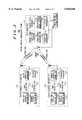
- FIG. 1is a schematic representation of a preferred embodiment of a symbol pulse shape function, g v (t) utilized by the present invention.
- FIG. 2is a schematic representation illustrating two modulated data carrier signals, with each modulated data carrier signal having a distinct carrier frequency, but with overlapping signal spectra, wherein the modulated data carrier signals are from two separate overlap bandwidth subscriber units, each of which simultaneously transmits a reverse link signal in accordance with the present invention.
- FIG. 3is a schematic illustrating a multiple-user two-way wireless communication system in accordance with the present invention.
- FIG. 4is a schematic illustrating an overlap bandwidth subscriber unit containing a digital signal processor/application specific integrated circuit in accordance with the present invention.
- the present inventionprovides a two-way communication system which enables the use of bandwidth efficient spectrally overlapping transmissions on the reverse link, where multiple reverse link transmissions occur simultaneously from a plurality of subscriber units, hereafter referred to as overlap bandwidth subscriber units because their reverse link signal frequency spectra may overlap. Simultaneous reverse link transmissions may occur, for example, in a system using a Frequency Division Multiple Access (FDMA) method, or a combined FDMA/TDMA method when multiple subscriber units are transmitting within the same time slot interval.
- FDMAFrequency Division Multiple Access
- the present inventionenables the reverse link of the two-way communication system to obtain bandwidth efficiency similar to that of the forward link of the two-way communication system assuming OFDM is used in the forward link of the two-way communication system.
- the reverse link signalis a digitally modulated signal that includes one or more modulated data carrier signals.
- a modulated data carrier signalis a carrier which is modulated by a digital information source in the transmitting unit, where the modulation method may comprise M-ary Quadrature Phase Shift Keying (M-PSK), M-ary Quadrature Amplitude Modulation (QAM), or any other digital modulation method which may be known in the art.
- M-PSKM-ary Quadrature Phase Shift Keying
- QAMM-ary Quadrature Amplitude Modulation
- each of the carriersis commonly referred to as a subcarrier or a tone.
- a modulated data carrier signalhas an associated carrier frequency, symbol time reference, and symbol pulse-shape function.
- the symbol time referencedetermines the symbol timing when a reverse link transmission occurs.
- the pulse-shape function for the modulating symbols on a modulated data carrier signalis selected from any of the known OFDM compatible pulse-shapes.
- pulse-shape functionshave a constant value over the pulse-shape function duration. If the pulse-shape function holds a constant value over the entire pulse-shape duration, the function is commonly referred to as a rectangular pulse-shape function.
- a preferred embodiment of a pulse shape function, g v (t),is defined in the following equation and is shown in FIG. 1, numeral 100. ##EQU1##
- the portion of the pulse shape from 0 to t sis hereafter referred to the useful symbol portion, and t s is hereafter referred to as the useful symbol duration.
- the portion of the pulse shape from t s to T sis a symbol extension portion commonly referred to as a cyclic extension, periodic extension, or guard interval.
- the cyclic extension portionmay be placed before the useful symbol portion instead of after the useful symbol portion, in which case it may also be referred to as a cyclic prefix.
- a cyclic extensionis sometimes used in OFDM to improve performance in the presence of a multipath channel.
- this signalmay transmitted on a forward link by a single base unit to a plurality of overlap bandwidth subscriber units.
- the following equationshows an OFDM signal, x(t), based on the defined pulse shape function, g v (t).
- the number of subcarriers used for transmissionis given by N.
- Transmitted symbolsare given by X km and channel attenuation and phase rotation are given by A(t)e j ⁇ (t). ##EQU2##
- any overlap bandwidth subscriber unitis able to detect the data on any of the modulated data carriers without interference from the other modulated data carriers. This detection is performed by integrating the received OFDM signal over a constant time window of length t s .
- the equation belowshows the detection of the n th symbol in time by the p th overlap bandwidth subscriber unit given the reception of the OFDM signal, x(t). ##EQU3##
- the modulated data carrier signalsare from two separate overlap bandwidth subscriber units, each of which simultaneously transmits a reverse link signal that has a modulated data carrier signal, with each modulated data carrier signal having a distinct carrier frequency, but with overlapping signal spectra as shown in FIG. 2, numeral 200.
- the overlap bandwidth subscriber unitssince they are physically separated, they contain separate local frequency, time, and phase references. These local references are commonly based on a local oscillator contained within each overlap bandwidth subscriber unit.
- the attenuation and phase rotation of the second overlap bandwidth subscriber unit reverse link signalmay differ from the first due to propagation path differences.
- a composite signal received at the base unit that includes the sum of the reverse link signals from the two overlap bandwidth subscriber unitsmay be written as shown in the following equation.
- the interference term in the above equationdisappears as the mismatch in symbol timing approaches zero.
- the timing referencesmay differ by an amount as large as the cyclic extension duration. In other words, assuming that the two reverse link signals arrive at the base unit spaced exactly in frequency by 1/t s , the requirement on the symbol timing of the second reverse link signal is - ⁇ t s ⁇ 1 ⁇ 0 for it not to interfere with the first reverse link signal.
- the local frequency reference and symbol time reference of each overlap bandwidth subscriber unitmust be controlled in a predetermined manner by the communication system.
- the frequency reference requirementis that the modulated data carrier frequencies be spaced by integer multiples of 1/t s .
- the time reference requirementis that all reverse link signals arrive at the base unit with the same symbol timing, which means that the beginning of a received symbol is at the same timing phase relative to a base unit symbol clock regardless of which subscriber unit transmitted the symbol. Note that as the previous equations show, differences in the amplitudes and phase rotations of the reverse link signals arriving at the base unit do not cause interference if the frequency and symbol timing parameters are properly controlled.
- a bandwidth-efficient multiple user reverse linkmay be implemented by utilizing a frequency spacing of as little as 1/t s between the modulated data carriers from separate overlap bandwidth subscriber unit reverse link signals, and that mutual interference can be avoided even though the spectra of the reverse link signals overlap as shown in FIG. 2.
- each overlap bandwidth subscriber unitmust derive a symbol timing reference from the forward link signal.
- the symbol timing referencemay be derived in an open-loop fashion or a closed-loop fashion.
- an overlap bandwidth subscriber unitderives a symbol timing reference from the received forward link signal.
- the overlap bandwidth subscriber unitderives a reverse link symbol timing reference from the symbol timing of the forward link signal.
- the overlap bandwidth subscriber unitdetermines the symbol timing of the received forward link signal using one of the symbol timing recovery methods known in the art.
- the symbol timing reference derived from the symbol timing of the received forward link signalis then used as a symbol timing reference for the transmission of a reverse link signal by the overlap bandwidth subscriber unit.
- a subscriber unitcontains a local oscillator, as is known in the art, which is used to provide an initial local symbol clock, and that the derived symbol timing reference from the forward link signal may be used to modify the local symbol clock.
- the overlap bandwidth subscriber unitmay optionally advance the symbol timing reference of the reverse link by an amount equal to the signal delay introduced by analog and digital processing chains in the overlap bandwidth subscriber unit transmitter and receiver.
- Open-loop symbol time reference methodsare typically appropriate for geographically small two-way communication systems where propagation delays within the system coverage area are negligible. In order to be considered negligible, the propagation delay must be much smaller than t s , for example less than 1% of t s .
- closed-loop timing advancean overlap bandwidth subscriber unit transmits a reverse link signal to the base unit.
- the base unitmeasures a symbol time offset in the received reverse link signal.
- the symbol time offsetis the difference in time between the symbol timing of the received reverse link signal and a base unit reference expected received signal symbol timing.
- the base unitcalculates a time advance value which needs to be introduced in the overlap bandwidth subscriber unit symbol time reference to eliminate the symbol time offset.
- the time advance valueis typically equal to the measured symbol time offset.
- the base unitthen transmits the time advance value to the overlap bandwidth subscriber unit on the forward link.
- the overlap bandwidth subscriber unitreceives the time advance value and adjusts its transmit symbol time reference by the received time advance value.
- the adjusted transmit symbol time referenceis used to determine the symbol timing of subsequent reverse link transmissions.
- each overlap bandwidth subscriber unitmust derive a frequency reference from the forward link signal transmitted by the base unit.
- the forward link signalcontains known data portions which are periodically transmitted.
- the overlap bandwidth subscriber unitreceives the forward link signal and uses the known data portions to derive an accurate frequency reference which is effectively locked to the base unit frequency reference. Suitable methods for deriving the frequency reference in a overlap bandwidth subscriber unit, such as automatic frequency control are known in the art.
- FIG. 3illustrates a multiple-user two-way wireless communication system 300 in accordance with the present invention.
- a service access pointis provided by base unit 310.
- Base unit 310provides simultaneous service to a plurality of overlap bandwidth subscriber units, including, but not limited to, overlap bandwidth subscriber units 320 and 330.
- base unit 310also provides connectivity to another network such as the PSTN 340.
- the communication link from base unit 310 to an overlap bandwidth subscriber unitwill hereafter be referred to as a forward link.
- the communication link from a overlap bandwidth subscriber unit to base unit 310will hereafter be referred to as a reverse link.
- the forward link signal transmitted by base unit 310includes an OFDM signal.
- a data streamis fed into base unit 310 from the PSTN 340.
- the data streamis separated into a number of parallel lower data rate streams, each of which modulates a separate data carrier signal using OFDM.
- this modulationis done digitally using an Inverse Fast Fourier Transform, hereafter referred to as an IFFT.
- IFFTInverse Fast Fourier Transform
- this modulationmay be done in an analog fashion.
- Base unit 310receives a composite signal comprising a plurality of reverse link signals from overlap bandwidth subscriber units and detects the reverse link signal of each overlap bandwidth subscriber unit.
- the demodulation/detection of the reverse link signalsmay be implemented with an OFDM demodulator/detector.
- a plurality of overlap bandwidth subscriber unitsincludes the two overlap bandwidth subscriber units 320 and 330.
- the inventionis fully applicable to systems containing a larger number of overlap bandwidth subscriber units.
- a plurality of overlap bandwidth subscriber unitsreceive the forward link signal, and each derives a frequency reference from the forward link signal.
- Each overlap bandwidth subscriber unitpreferably derives the frequency reference from the forward link signal using an automatic frequency control, as is known in the art.
- Each overlap bandwidth subscriber unitalso derives a symbol timing reference from the forward link signal, as described earlier.
- a plurality of overlap bandwidth subscriber unitstransmit reverse link signals to the base unit simultaneously with a symbol timing based on the symbol timing reference derived from the forward link signal, and with the spectra of the plurality of reverse link signals overlapping.
- Each reverse link signalincludes one or more modulated data carrier signals.
- the carrier frequencies for the reverse link modulated data carriersare selected from a set of allowable reverse link carrier frequencies.
- the set of allowable carrier frequenciesis affected by factors including the system frequency band allocation and the bandwidth available in the system for reverse link transmissions.
- the set of allowable reverse link carrier frequenciesare spaced by integer multiples of 1/t s , where t s is the reverse link useful symbol duration.
- the set of spaced carrier frequenciesform a carrier frequency "grid".
- the values of the grid of carrier frequenciesare preferably predetermined and are stored and labeled in the base unit and overlap bandwidth subscriber unit.
- the accuracy of the carrier frequencies of the reverse link modulated data carrier signalsis dependent on the accuracy of the frequency reference of the overlap bandwidth subscriber unit.
- the accuracy of the overlap bandwidth subscriber unit frequency referencegenerally depends on the accuracy of a local oscillator in the overlap bandwidth subscriber unit. Inaccuracies in the local oscillator are preferably eliminated by deriving a frequency reference from the forward link signal using automatic frequency control, as described earlier. Since a frequency reference is derived from the forward link signal, the carrier frequencies of the modulated data carriers generated by the overlap bandwidth subscriber unit will coincide with elements of the carrier frequency grid in the base unit.
- the specific carrier frequencies used by a particular overlap bandwidth subscriber unit for its reverse link modulated data carriersmay be determined in a number of ways.
- the base unitincludes in the transmitted forward link signal, a list of reverse link carrier frequencies from the set of allowable reverse link carrier frequencies which are available (i.e., carrier frequencies which are not currently being used by an overlap bandwidth subscriber unit).
- the overlap bandwidth subscriber unitselects reverse link carrier frequencies from the list for its reverse link modulated data carriers.
- the carrier frequencies used by separate overlap bandwidth subscriber units for reverse link transmissionsare distinct to avoid directly coincident signal spectra from separate overlap bandwidth subscriber units.
- the overlap bandwidth subscriber unit reverse link signalincludes a plurality of modulated data carriers
- the plurality of modulated data carriersis at least in part preferably generated digitally using an Inverse Discrete Fourier Transform (IDFT), as is known in the art.
- IDFTmay be efficiently implemented using the Inverse Fast Fourier Transform, as is known in the art.
- the overlap bandwidth subscriber unitsfurther include a cyclic extension portion in the pulse shape function of the modulated data carrier signals.
- a cyclic extension portion duration of ⁇ t seliminates mutual interference in reverse link signals when the symbol timing of the received reverse link signals at the base unit is different up to a maximum value of ⁇ t s .
- a cyclic extensionenables mutual interference to be avoided even when there are moderate inaccuracies in the symbol time references of the overlap bandwidth subscriber units.
- Another preferred embodiment of the present inventionincludes the use of reverse link power control.
- reverse link power controlAs described earlier, if the symbol time reference and frequency reference of each overlap bandwidth subscriber unit are controlled appropriately, then mutual interference among the overlap bandwidth subscriber units transmitting reverse link may be avoided. If, however, the time and frequency references of the overlap bandwidth subscriber units are not controlled properly, then mutual interference will occur. In this case, as the previous equations indicate, the amount of interference is responsive to the relative amplitudes of the reverse link signals. The amount of interference will increase significantly if some overlap bandwidth subscriber unit reverse link signals arrive at the base unit with substantially larger amplitude than other overlap bandwidth subscriber unit reverse link signals. Therefore, reverse link power control is useful to limit the interference level in the case of parameter mismatches. Reverse link power control methods are known in the art.
- the overlap bandwidth subscriber unitadjusts the reverse link transmit power in accordance with a predetermined reference reverse link expected received power of the base unit.
- the base unitcompares a received reverse link signal power to a desired reverse link signal power. If the received power is not substantially close to the desired power, the base unit determines whether the overlap bandwidth subscriber unit transmit power needs to be increased or decreased to bring the received power closer to the desired power. Using the forward link, the base unit sends a power increase or power decrease message to the overlap bandwidth subscriber unit according to whether the received power was less than or greater than the desired power, respectively.
- overlap bandwidth subscriber unit 320includes a receiver 326, an overlap bandwidth transmitter 325, a frequency reference derivation unit 322, and a symbol time reference derivation unit 321.
- Receiver 326 and overlap bandwidth transmitter 325are operably coupled to an antenna for wireless communication.
- the overlap bandwidth transmitter and receiverare operably coupled to the communication system wiring infrastructure.
- Receiver 326is used for receiving a forward link signal which has been transmitted by base unit 310.
- Receiver 326preferably filters, amplifies, and downconverts the received signal.
- Receiver 326also preferably converts the received signal to digital form and detects the information contained in the received signal.
- the forward link signalpreferably includes an OFDM signal, and the detection is preferably based on a Discrete Fourier Transform (DFT), which may be efficiently implemented with a Fast Fourier Transform (FFT), as is known in the art.
- DFTDiscrete Fourier Transform
- FFTFast Fourier Transform
- Overlap bandwidth transmitter 325is used for transmitting a reverse link signal to base unit 310.
- the transmitted reverse link signalincludes one or more modulated data carrier signals having distinct carrier frequencies. Preferred methods for determining the carrier frequencies for the modulated data carrier signals were described earlier. If the overlap bandwidth subscriber unit reverse link signal includes a plurality of modulated data carriers, the plurality of modulated data carriers is at least in part preferably generated digitally using an Inverse Discrete Fourier Transform (IDFT), as is known in the art. The IDFT can be efficiently implemented using the Inverse Fast Fourier Transform, as is known in the art.
- Overlap bandwidth transmitter 325preferably converts the digital form of the sum of the modulated data carriers to an analog signal, filters, upconverts, and amplifies the signal for transmission.
- the spectrum of the reverse link signalextends into regions of the frequency band which may be used by other overlap bandwidth subscriber units such as overlap bandwidth subscriber unit 330, in a similar fashion to what was illustrated in FIG. 1. Even though the spectrum of the reverse link signal extends into regions of the frequency band which may be used by other overlap bandwidth subscriber units, overlap bandwidth subscriber unit 320 does not interfere with other reverse link communications, as the previous equations indicate.
- Frequency reference derivation unit 322derives a frequency reference from the received forward link signal, and determines a carrier frequency for one or more modulated data carrier signals for the reverse link signal based in part on the derived frequency reference.
- the forward link signalcontains known data portions which are periodically transmitted.
- the overlap bandwidth subscriber unitreceives the forward link signal and uses the known data portions to derive an accurate frequency reference which is effectively locked to the base unit frequency reference. Suitable methods for deriving the frequency reference in a overlap bandwidth subscriber unit, such as automatic frequency control are known in the art.
- a preferred method for determining the carrier frequencies for the reverse link signal by selecting carrier frequencies from a set of allowable reverse link carrier frequencieswas described earlier.
- base unit 310measures a frequency offset in the reverse link signal and sends a frequency adjust message to the subscriber unit on the forward link.
- Symbol time reference derivation unit 321derives a symbol timing reference from the forward link signal, and adjusts the symbol timing of the reverse link transmitted signal responsive to the derived symbol timing reference.
- the symbol timing referencecan be derived with an open-loop or a closed-loop method.
- the overlap bandwidth subscriber unitderives a reverse link symbol timing reference from the symbol timing of the received forward link signal.
- the overlap bandwidth subscriber unitdetermines the symbol timing of the received forward link signal using one of the symbol timing recovery methods known in the art.
- the symbol timing reference derived from the symbol timing of the received forward link signalis then used as a symbol timing reference for the transmission of a reverse link signal by the overlap bandwidth subscriber unit.
- the overlap bandwidth subscriber unitmay optionally advance the symbol timing reference of the reverse link by an amount equal to the signal delay introduced by analog and digital processing chains in the overlap bandwidth subscriber unit transmitter and receiver.
- Open-loop symbol time reference methodsare typically appropriate for geographically small two-way communication systems where propagation delays within the system coverage area are negligible. In order to be considered negligible, the propagation delay must be much smaller than t s , for example less than 1% of t s .
- a preferred embodiment of a closed-loop time reference derivation methodis timing advance, hereinafter referred to as closed-loop timing advance to emphasize the closed-loop aspect.
- closed-loop timing advancea overlap bandwidth subscriber unit transmits a reverse link signal to the base unit.
- the base unitmeasures a symbol time offset in the received reverse link signal.
- the symbol time offsetis the difference in time between the symbol timing of the received reverse link signal and a base unit reference expected received signal symbol timing.
- the base unitcalculates a time advance value which needs to be introduced in the overlap bandwidth subscriber unit symbol timing to eliminate the symbol time offset.
- the time advance valueis typically equal to the measured symbol time offset.
- the base unittransmits the time advance value to the overlap bandwidth subscriber unit on the forward link.
- the overlap bandwidth subscriber unitreceives the time advance value and the symbol time reference derivation unit 321 adjusts the symbol timing of subsequent reverse link transmitted signals by the received time advance value.
- subscriber unit 320additionally includes a cyclic extension unit 324.
- Cyclic extension unit 324is used for extending the duration of the data symbols which modulate the modulated data carriers for the reverse link signal.
- the extended symbolincludes a useful symbol portion and a symbol extension portion, as defined earlier.
- the overlap bandwidth subscriber unit reverse link signalincludes a plurality of modulated data carriers, with the plurality of modulated data carriers preferably generated digitally using an Inverse Discrete Fourier Transform (IDFT), which can be efficiently implemented using the Inverse Fast Fourier Transform, as is known in the art.
- IDFTInverse Discrete Fourier Transform
- a preferred embodiment of cyclic extension unit 324generates the symbol extension portion for the group of modulated data carriers by first duplicating a portion of the IDFT output vector and then appending the duplicated vector portion to the original IDFT output vector, as is known in the art.
- a cyclic extension portion duration of ⁇ t seliminates mutual interference in reverse link signals when the symbol timing of the received reverse link signals at the base unit is different up to a maximum value of ⁇ t s .
- a cyclic extensionenables mutual interference to be avoided even when there are moderate inaccuracies in the symbol time references of the overlap bandwidth subscriber units.
- a cyclic extensionreduces the system bandwidth efficiency in proportion to the duration of the cyclic extension, so the cyclic extension portion should be made only as large as necessary.
- subscriber unit 320additionally includes a power control unit 323 for adjusting a transmit power of the reverse link signal in accordance with a predetermined reference reverse link expected received power of the base unit.
- the base unitcompares a received reverse link signal power to a desired reverse link signal power. If the received power is not close to the desired power, the base unit determines whether the overlap bandwidth subscriber unit transmit power needs to be increased or decreased to bring the received power closer to the desired power. Using the forward link, the base unit sends a power increase or power decrease message to the overlap bandwidth subscriber unit according to whether the received power was less than or greater than the desired power, respectively.
- the power control unitthen adjusts the reverse link transmit power on subsequent reverse link transmissions in response to the power adjust message.
- symbol time reference derivation unit 321, frequency reference derivation unit 322, power control unit 323, and cyclic extension unit 324may be implemented within hardware, or within a combination of software and hardware, as indicated in FIG. 4, numeral 400.
- a hardware implementationpreferably includes an Application Specific Integrated Circuit (ASIC).
- a combined software/hardware implementationpreferably includes a Digital Signal Processor (DSP) executing a stored program.
- DSPDigital Signal Processor
- the base unit 310includes a transmitter 315 for transmitting a forward link signal, a receiver 316 for receiving a composite signal for a plurality of reverse link signals from overlap bandwidth subscriber units including, but not limited to overlap bandwidth subscriber units 320 and 330, and an overlapped signal spectra detector 314, for detecting a transmit signal from each of a plurality of overlap bandwidth subscriber units, to facilitate communication using overlapped transmit signal spectra of at least two overlap bandwidth subscriber units.
- Receiver 316preferably filters, amplifies, and downconverts the composite received signal. Receiver 316 also preferably converts the received signal to digital form with an analog to digital converter and passes the digital form signal to overlapped signal spectra detector 314. Overlapped signal spectra detector 314 detects and separates the individual reverse link signals from the composite received signal comprising a plurality of reverse link signals prior to passing the detected reverse link signals to the public switched telephone network 340. Detection of the individual reverse link signals from the composite received signal is preferably based on a discrete Fourier Transform (DFT), which may be efficiently implemented using a Fast Fourier Transform (FFT), as is known in the art.
- DFTdiscrete Fourier Transform
- FFTFast Fourier Transform
- base/headend unit 310includes a received symbol timing offset calculator 311 for measuring a symbol timing offset of a received reverse link signal transmitted by an overlap bandwidth subscriber unit, and for generating a symbol timing reference adjustment value to be transmitted to the subscriber unit on the forward link.
- a received symbol timing offset calculator 311for measuring a symbol timing offset of a received reverse link signal transmitted by an overlap bandwidth subscriber unit, and for generating a symbol timing reference adjustment value to be transmitted to the subscriber unit on the forward link.
- base unit 310includes a power measurement control unit 313 for measuring a signal power of a received reverse link signal transmitted by an overlap bandwidth subscriber unit, for comparing the signal power to an expected signal power, and for generating a reverse link transmit power adjustment value to be transmitted to the subscriber unit on the forward link.
- base unit 310includes a frequency offset measurement unit 312 for measuring a frequency offset of a received reverse link signal transmitted by an overlap bandwidth subscriber unit, and for generating a reverse link frequency reference adjustment value to be transmitted to the subscriber unit on the forward link.
Landscapes
- Engineering & Computer Science (AREA)
- Signal Processing (AREA)
- Computer Networks & Wireless Communication (AREA)
- Mobile Radio Communication Systems (AREA)
Abstract
Description
Claims (31)
Priority Applications (8)
| Application Number | Priority Date | Filing Date | Title |
|---|---|---|---|
| US08/639,370US5828660A (en) | 1996-04-26 | 1996-04-26 | Multiple user communication system, device and method with overlapping uplink carrier spectra |
| PCT/US1997/006081WO1997041645A1 (en) | 1996-04-26 | 1997-04-11 | Multiple user communication system, device and method with overlapping uplink carrier spectra |
| EP10009538AEP2259436B1 (en) | 1996-04-26 | 1997-04-11 | Multiple user communication system, device and method with overlapping uplink carrier spectra |
| EP97921159AEP0861529B1 (en) | 1996-04-26 | 1997-04-11 | Multiple user communication system, device and method with overlapping uplink carrier spectra |
| CA002223982ACA2223982C (en) | 1996-04-26 | 1997-04-11 | Multiple user communication system, device and method with overlapping uplink carrier spectra |
| KR1019970709751AKR100260863B1 (en) | 1996-04-26 | 1997-04-11 | Multi-user communication system, apparatus and method having overlapping uplink carrier spectrum |
| AU27278/97AAU692737B2 (en) | 1996-04-26 | 1997-04-11 | Multiple user communication system, device and method with overlapping uplink carrier spectra |
| DE69740009TDE69740009D1 (en) | 1996-04-26 | 1997-04-11 | MULTIPLE USER COMMUNICATION SYSTEM AND METHOD AND DEVICE HAVING OVERCLUDING UPWARD PERFORMANCE |
Applications Claiming Priority (1)
| Application Number | Priority Date | Filing Date | Title |
|---|---|---|---|
| US08/639,370US5828660A (en) | 1996-04-26 | 1996-04-26 | Multiple user communication system, device and method with overlapping uplink carrier spectra |
Publications (1)
| Publication Number | Publication Date |
|---|---|
| US5828660Atrue US5828660A (en) | 1998-10-27 |
Family
ID=24563819
Family Applications (1)
| Application Number | Title | Priority Date | Filing Date |
|---|---|---|---|
| US08/639,370Expired - LifetimeUS5828660A (en) | 1996-04-26 | 1996-04-26 | Multiple user communication system, device and method with overlapping uplink carrier spectra |
Country Status (7)
| Country | Link |
|---|---|
| US (1) | US5828660A (en) |
| EP (2) | EP2259436B1 (en) |
| KR (1) | KR100260863B1 (en) |
| AU (1) | AU692737B2 (en) |
| CA (1) | CA2223982C (en) |
| DE (1) | DE69740009D1 (en) |
| WO (1) | WO1997041645A1 (en) |
Cited By (34)
| Publication number | Priority date | Publication date | Assignee | Title |
|---|---|---|---|---|
| KR20000061550A (en)* | 1999-03-27 | 2000-10-25 | 이원근 | Data Transmission and Reception Device for channel capacity increase(Trubitsin's scheme for channel capacity increase) |
| US6160791A (en)* | 1997-08-29 | 2000-12-12 | Sony International (Europe) Gmbh | Transmission system for the transmission of power control information in an OFDM system |
| WO2001030003A1 (en)* | 1999-10-22 | 2001-04-26 | Nextnet Wireless Inc. | Fixed ofdm wireless man utilizing cpe having internal antenna |
| US6292651B1 (en) | 1995-02-06 | 2001-09-18 | Adc Telecommunications, Inc. | Communication system with multicarrier transport distribution network between a head end terminal and remote units |
| WO2001048969A3 (en)* | 1999-12-29 | 2002-01-10 | Atheros Comm Inc | Multiuser ofdm or dmt communications system for users transmitting at different data rates |
| US20020015382A1 (en)* | 2000-06-14 | 2002-02-07 | Kunio Fukuda | Radio communication system, radio base-station apparatus, mobile radio-station apparatus, radio-zone assignment method, and radio communication method |
| US20020061031A1 (en)* | 2000-10-06 | 2002-05-23 | Sugar Gary L. | Systems and methods for interference mitigation among multiple WLAN protocols |
| US20020147978A1 (en)* | 2001-04-04 | 2002-10-10 | Alex Dolgonos | Hybrid cable/wireless communications system |
| US20040042576A1 (en)* | 2002-08-27 | 2004-03-04 | Anderson Joh J. | Synchronizing timing between multiple air link standard signals operating within a communications terminal |
| US6842435B1 (en)* | 1999-09-15 | 2005-01-11 | General Instrument Corporation | Congestion monitoring and power control for a communication system |
| US6970416B1 (en) | 2000-07-07 | 2005-11-29 | Telecommunications Research Laboratories | OFDM system with simple terminals |
| US20060029029A1 (en)* | 2004-08-09 | 2006-02-09 | Jacobsen Eric A | Apparatus and method capable of wireless communication using channel management |
| US7002934B2 (en) | 2001-01-22 | 2006-02-21 | Unique Broadband Systems, Inc. | OFDM multiple upstream receiver network |
| US20060067446A1 (en)* | 2004-09-30 | 2006-03-30 | Ntt Docomo, Inc. | Signal detector used in wireless communication system |
| US20060087972A1 (en)* | 2001-11-21 | 2006-04-27 | Ahmad Jalali | Rate selection for an OFDM system |
| WO2006045097A2 (en) | 2004-10-20 | 2006-04-27 | Qualcomm Incorporated | Multiple frequency band operation in wireless networks |
| US20060117361A1 (en)* | 2004-11-05 | 2006-06-01 | Alex Dolgonos | Data communications system using CATV network with wireless return path |
| US20060159003A1 (en)* | 2004-10-20 | 2006-07-20 | Qualcomm Incorporated | Multiple frequency band operation in wireless networks |
| US20060270433A1 (en)* | 2005-05-31 | 2006-11-30 | Kelton James R | Adjusting transmit power of a wireless communication device |
| US20070058742A1 (en)* | 2005-09-09 | 2007-03-15 | Demarco Anthony | Distributed antenna system using signal precursors |
| US20070171995A1 (en)* | 2006-01-25 | 2007-07-26 | Tarik Muharemovic | Method and Apparatus for Increasing the Number of Orthogonal Signals Using Block Spreading |
| US20070183386A1 (en)* | 2005-08-03 | 2007-08-09 | Texas Instruments Incorporated | Reference Signal Sequences and Multi-User Reference Signal Sequence Allocation |
| US20090170448A1 (en)* | 2003-09-19 | 2009-07-02 | Interdigital Patent Holdings, Inc. | Master-slave local oscillator porting between radio integrated circuits |
| US20090201951A1 (en)* | 2008-01-11 | 2009-08-13 | Lg Electronics Inc. | Method and adjusting transmission timing and transmitting continuous packets and mobile station thereof |
| US7577165B1 (en)* | 2003-02-05 | 2009-08-18 | Barrett Terence W | Method and system of orthogonal signal spectrum overlay (OSSO) for communications |
| USRE41771E1 (en) | 1995-02-06 | 2010-09-28 | Adc Telecommunications, Inc. | System for multiple use subchannels |
| US20110007701A1 (en)* | 2008-03-05 | 2011-01-13 | Shimpei To | Communication system, communication device and communication method |
| USRE42236E1 (en) | 1995-02-06 | 2011-03-22 | Adc Telecommunications, Inc. | Multiuse subcarriers in multipoint-to-point communication using orthogonal frequency division multiplexing |
| US20120106751A1 (en)* | 2010-08-25 | 2012-05-03 | Qualcomm Incorporated | Methods and apparatus for wireless microphone synchronization |
| US8363757B1 (en) | 1999-10-12 | 2013-01-29 | Qualcomm Incorporated | Method and apparatus for eliminating the effects of frequency offsets in a digital communication system |
| US20140185594A1 (en)* | 2007-08-13 | 2014-07-03 | Sharp Kabushiki Kaisha | Radio communication system, radio communication method, radio communication device, reception device, and program |
| CN104615101A (en)* | 2014-12-16 | 2015-05-13 | 浙江大丰实业股份有限公司 | Stage multi-dimensional system synchronous control method |
| EP3512242A4 (en)* | 2016-09-30 | 2019-11-13 | Huawei Technologies Co., Ltd. | Method and device for controlling signal transmission |
| EP3873141A4 (en)* | 2018-10-25 | 2022-01-26 | ZTE Corporation | METHOD AND DEVICE FOR DETERMINING THE REFERENCE TIME, AS WELL AS STORAGE MEDIUM AND ELECTRONIC DEVICE |
Families Citing this family (2)
| Publication number | Priority date | Publication date | Assignee | Title |
|---|---|---|---|---|
| US5867478A (en)* | 1997-06-20 | 1999-02-02 | Motorola, Inc. | Synchronous coherent orthogonal frequency division multiplexing system, method, software and device |
| WO1999044316A1 (en)* | 1998-02-26 | 1999-09-02 | Sony Corporation | Communication system, base station apparatus, communication terminal apparatus and communication method |
Citations (6)
| Publication number | Priority date | Publication date | Assignee | Title |
|---|---|---|---|---|
| US5012490A (en)* | 1989-12-26 | 1991-04-30 | At&T Bell Laboratories | Varying bandwidth digital signal detector |
| US5140697A (en)* | 1989-01-24 | 1992-08-18 | Fujitsu Limited | Subscriber station of subscriber radio system which do not interfere with each other |
| US5257404A (en)* | 1991-10-04 | 1993-10-26 | Motorola, Inc. | Simulcast synchronization and equalization system and method therefor |
| US5261118A (en)* | 1991-10-04 | 1993-11-09 | Motorola, Inc. | Simulcast synchronization and equalization system and method therefor |
| US5459760A (en)* | 1993-11-05 | 1995-10-17 | Matsushita Electric Industrial Co., Ltd. | Transmitting and receiving apparatus |
| US5551066A (en)* | 1993-06-07 | 1996-08-27 | Radio Local Area Networks, Inc. | Network link controller for dynamic designation of master nodes |
- 1996
- 1996-04-26USUS08/639,370patent/US5828660A/ennot_activeExpired - Lifetime
- 1997
- 1997-04-11WOPCT/US1997/006081patent/WO1997041645A1/enactiveIP Right Grant
- 1997-04-11DEDE69740009Tpatent/DE69740009D1/ennot_activeExpired - Lifetime
- 1997-04-11EPEP10009538Apatent/EP2259436B1/ennot_activeExpired - Lifetime
- 1997-04-11KRKR1019970709751Apatent/KR100260863B1/ennot_activeExpired - Lifetime
- 1997-04-11AUAU27278/97Apatent/AU692737B2/ennot_activeExpired
- 1997-04-11CACA002223982Apatent/CA2223982C/ennot_activeExpired - Lifetime
- 1997-04-11EPEP97921159Apatent/EP0861529B1/ennot_activeExpired - Lifetime
Patent Citations (6)
| Publication number | Priority date | Publication date | Assignee | Title |
|---|---|---|---|---|
| US5140697A (en)* | 1989-01-24 | 1992-08-18 | Fujitsu Limited | Subscriber station of subscriber radio system which do not interfere with each other |
| US5012490A (en)* | 1989-12-26 | 1991-04-30 | At&T Bell Laboratories | Varying bandwidth digital signal detector |
| US5257404A (en)* | 1991-10-04 | 1993-10-26 | Motorola, Inc. | Simulcast synchronization and equalization system and method therefor |
| US5261118A (en)* | 1991-10-04 | 1993-11-09 | Motorola, Inc. | Simulcast synchronization and equalization system and method therefor |
| US5551066A (en)* | 1993-06-07 | 1996-08-27 | Radio Local Area Networks, Inc. | Network link controller for dynamic designation of master nodes |
| US5459760A (en)* | 1993-11-05 | 1995-10-17 | Matsushita Electric Industrial Co., Ltd. | Transmitting and receiving apparatus |
Non-Patent Citations (4)
| Title |
|---|
| "Analysis and Simulation of a Digital Mobile Channel Using Orthoganal Frequency Division Multiplexing", Leonard J. Cimini, Jr IEEE Transactions on communications, vol. Com-33, No. 7, Jul. 1985, pp. 665-675. |
| "Frequency Synchronization Algorithms for OFDM Systems suitable for Communication over Frequency Selective Fading Channels", Ferdinand Classen, Heinrich Meyer, 1994 IEEE, pp. 1655-1659. |
| Analysis and Simulation of a Digital Mobile Channel Using Orthoganal Frequency Division Multiplexing , Leonard J. Cimini, Jr IEEE Transactions on communications, vol. Com 33, No. 7, Jul. 1985, pp. 665 675.* |
| Frequency Synchronization Algorithms for OFDM Systems suitable for Communication over Frequency Selective Fading Channels , Ferdinand Classen, Heinrich Meyer, 1994 IEEE, pp. 1655 1659.* |
Cited By (129)
| Publication number | Priority date | Publication date | Assignee | Title |
|---|---|---|---|---|
| US9094842B2 (en)* | 1994-09-26 | 2015-07-28 | Htc Corporation | Systems and method for orthogonal frequency divisional multiplexing |
| US20130121131A1 (en)* | 1994-09-26 | 2013-05-16 | Htc Corporation | Systems and method for orthogonal frequency divisional multiplexing |
| USRE44460E1 (en) | 1994-09-26 | 2013-08-27 | Htc Corporation | Systems for synchronous multipoint-to-point orthogonal frequency division multiplexing communication |
| US8547824B2 (en) | 1994-09-26 | 2013-10-01 | Htc Corporation | Systems and methods for orthogonal frequency divisional multiplexing |
| US8638655B2 (en)* | 1994-09-26 | 2014-01-28 | Htc Corporation | Systems and method for orthogonal frequency divisional multiplexing |
| US20140105263A1 (en)* | 1994-09-26 | 2014-04-17 | Htc Corporation | Systems and method for orthogonal frequency divisional multiplexing |
| US7706349B2 (en) | 1995-02-06 | 2010-04-27 | Adc Telecommunications, Inc. | Methods and systems for selecting modulation in an orthogonal frequency division multiplexing system |
| US8351321B2 (en) | 1995-02-06 | 2013-01-08 | Htc Corporation | Systems and method for orthogonal frequency divisional multiplexing |
| US20110255621A1 (en)* | 1995-02-06 | 2011-10-20 | Htc Corporation | Synchronized multipoint-to-point communication using orthogonal frequency division |
| US7535822B2 (en) | 1995-02-06 | 2009-05-19 | Adc Telecommunications, Inc. | Synchronization of remote units for a communication network |
| US6594322B2 (en)* | 1995-02-06 | 2003-07-15 | Adc Telecommunications, Inc. | Method of distributed loop control for a multicarrier telephony transport |
| USRE41771E1 (en) | 1995-02-06 | 2010-09-28 | Adc Telecommunications, Inc. | System for multiple use subchannels |
| US7995454B2 (en) | 1995-02-06 | 2011-08-09 | Htc Corporation | Systems and method for orthogonal frequency divisional multiplexing |
| US8213398B2 (en) | 1995-02-06 | 2012-07-03 | Htc Corporation | Method for multiple use subchannels |
| US7983141B2 (en)* | 1995-02-06 | 2011-07-19 | Geile Michael J | Synchronized multipoint-to-point communication using orthogonal frequency division |
| US6292651B1 (en) | 1995-02-06 | 2001-09-18 | Adc Telecommunications, Inc. | Communication system with multicarrier transport distribution network between a head end terminal and remote units |
| US8199632B2 (en) | 1995-02-06 | 2012-06-12 | Htc Corporation | Systems and method for orthogonal frequency divisional multiplexing |
| US7697453B2 (en) | 1995-02-06 | 2010-04-13 | Adc Telecommunications, Inc. | Synchronization techniques in multipoint-to-point communication using orthogonal frequency division multiplexing |
| US7675843B2 (en) | 1995-02-06 | 2010-03-09 | Adc Telecommunications, Inc. | Multipoint-to-point communication using orthogonal frequency division multiplexing |
| US7672219B2 (en) | 1995-02-06 | 2010-03-02 | Adc Telecommunications, Inc. | Multipoint-to-point communication using orthogonal frequency division multiplexing |
| US8213399B2 (en) | 1995-02-06 | 2012-07-03 | Htc Corporation | System for multiple use subchannels |
| US8315150B2 (en)* | 1995-02-06 | 2012-11-20 | Htc Corporation | Synchronized multipoint-to-point communication using orthogonal frequency division |
| US8089853B2 (en) | 1995-02-06 | 2012-01-03 | Htc Corporation | Systems and method for orthogonal frequency divisional multiplexing |
| US7957265B2 (en) | 1995-02-06 | 2011-06-07 | Adc Telecommunications, Inc. | Systems and method for orthogonal frequency divisional multiplexing |
| US7936662B2 (en) | 1995-02-06 | 2011-05-03 | Adc Telecommunications, Inc. | Ranging and round trip delay timing adjustment in a multi-point to point bidirectional communication system |
| US8576693B2 (en)* | 1995-02-06 | 2013-11-05 | Htc Corporation | Systems and method for orthogonal frequency division multiplexing |
| US7912138B2 (en) | 1995-02-06 | 2011-03-22 | Adc Telecommunications, Inc. | Timing and symbol alignment in multipoint-to-point communication using orthogonal frequency division multiplexing |
| USRE42236E1 (en) | 1995-02-06 | 2011-03-22 | Adc Telecommunications, Inc. | Multiuse subcarriers in multipoint-to-point communication using orthogonal frequency division multiplexing |
| US7881181B2 (en) | 1995-02-06 | 2011-02-01 | Adc Telecommunications, Inc. | Systems and method for orthogonal frequency divisional multiplexing |
| US7881180B2 (en) | 1995-02-06 | 2011-02-01 | Adc Telecommunications, Inc. | Systems and method for orthogonal frequency divisional multiplexing |
| US6366585B1 (en) | 1995-02-06 | 2002-04-02 | Adc Telecommunications, Inc. | Distributed control in a communication system |
| US7872985B2 (en) | 1995-02-06 | 2011-01-18 | Adc Dsl Systems, Inc. | System for multi-frame alignment |
| US7773537B2 (en) | 1995-02-06 | 2010-08-10 | Adc Telecommunications, Inc. | Ranging and round trip delay timing adjustment in a multi-point to point bidirectional communication system |
| US20120076183A1 (en)* | 1995-02-06 | 2012-03-29 | Htc Corporation | Systems and method for orthogonal frequency division multiplexing |
| US8174956B2 (en) | 1995-02-06 | 2012-05-08 | Htc Corporation | Systems and method for orthogonal frequency divisional multiplexing |
| US7756060B2 (en) | 1995-02-06 | 2010-07-13 | Adc Telecommunications, Inc. | Tone allocation in multipoint-to-point communication using orthogonal frequency division multiplexing |
| US8406115B2 (en) | 1995-02-06 | 2013-03-26 | Htc Corporation | Systems and methods for orthogonal frequency division multiplexing |
| US7310522B2 (en) | 1996-05-20 | 2007-12-18 | Adc Telecommunications, Inc. | Systems for synchronous multipoint-to-point orthogonal frequency division multiplexing communication |
| US7002898B1 (en)* | 1996-05-20 | 2006-02-21 | Adc Telecommunications, Inc. | Asymmetrical transport of data |
| US6608835B2 (en) | 1996-05-20 | 2003-08-19 | Adc Telecommunications, Inc. | Communication system with multicarrier telephony transport |
| US6467092B1 (en) | 1996-05-20 | 2002-10-15 | Adc Telecommunications Inc. | Method for adjusting power in a communication system with multicarrier telephony transport |
| US6160791A (en)* | 1997-08-29 | 2000-12-12 | Sony International (Europe) Gmbh | Transmission system for the transmission of power control information in an OFDM system |
| KR20000061550A (en)* | 1999-03-27 | 2000-10-25 | 이원근 | Data Transmission and Reception Device for channel capacity increase(Trubitsin's scheme for channel capacity increase) |
| US6842435B1 (en)* | 1999-09-15 | 2005-01-11 | General Instrument Corporation | Congestion monitoring and power control for a communication system |
| US8363757B1 (en) | 1999-10-12 | 2013-01-29 | Qualcomm Incorporated | Method and apparatus for eliminating the effects of frequency offsets in a digital communication system |
| US8767893B2 (en) | 1999-10-12 | 2014-07-01 | Qualcomm Incorporated | Method and apparatus for eliminating the effects of frequency offsets in a digital communication system |
| US20050176379A1 (en)* | 1999-10-22 | 2005-08-11 | Nextnet Wireless, Inc. | Fixed OFDM wireless MAN utilizing CPE having internal antenna |
| US7633893B2 (en) | 1999-10-22 | 2009-12-15 | Nextnet Wireless, Inc. | Fixed OFDM wireless man utilizing CPE having internal antenna |
| KR100769096B1 (en) | 1999-10-22 | 2007-10-23 | 넥스트넷 와이어리스 인크. | Fixed ofdm wireless man utilizing cpe having internal antenna |
| AU779339B2 (en)* | 1999-10-22 | 2005-01-20 | Google Technology Holdings LLC | Fixed OFDM wireless man utilizing CPE having internal antenna |
| WO2001030003A1 (en)* | 1999-10-22 | 2001-04-26 | Nextnet Wireless Inc. | Fixed ofdm wireless man utilizing cpe having internal antenna |
| AU2004200502B8 (en)* | 1999-10-22 | 2007-01-25 | Google Technology Holdings LLC | System and method for timing and frequency synchronisation in an OFDM communication system |
| AU2004200504B8 (en)* | 1999-10-22 | 2007-01-25 | Google Technology Holdings LLC | System and Method for Data Packet Delivery with a Framed Downlink and an Unframed Uplink |
| AU2004200504B2 (en)* | 1999-10-22 | 2006-11-02 | Google Technology Holdings LLC | System and Method for Data Packet Delivery with a Framed Downlink and an Unframed Uplink |
| US7626920B2 (en) | 1999-10-22 | 2009-12-01 | Nextnet Wireless, Inc. | Fixed OFDM wireless MAN utilizing CPE having internal antenna |
| KR100823420B1 (en) | 1999-10-22 | 2008-04-18 | 넥스트넷 와이어리스 인크. | Communication method between customer premises equipment unit and a plurality of base station units and fixed wireless system formation method |
| AU2004200502B2 (en)* | 1999-10-22 | 2006-11-02 | Google Technology Holdings LLC | System and method for timing and frequency synchronisation in an OFDM communication system |
| RU2255427C2 (en)* | 1999-10-22 | 2005-06-27 | Некстнет Уайрлесс Инк. | Orthogonal frequency division modulated stationary wireless regional network employing user's room equipment provided with indoor antenna |
| KR100769095B1 (en) | 1999-10-22 | 2007-10-23 | 넥스트넷 와이어리스 인크. | Fixed ofdm wireless man utilizing cpe having internal antenna |
| US20050186956A1 (en)* | 1999-10-22 | 2005-08-25 | Nextnet Wireless, Inc. | Fixed OFDM wireless man utilizing CPE having internal antenna |
| US20050176378A1 (en)* | 1999-10-22 | 2005-08-11 | Nextnet Wireless, Inc. | Fixed OFDM wireless man utilizing CPE having internal antenna |
| US20050171995A1 (en)* | 1999-10-22 | 2005-08-04 | Nextnet Wireless, Inc. | Fixed OFDM wireless MAN utilizing CPE having internal antenna |
| US7120166B2 (en) | 1999-12-29 | 2006-10-10 | Atheros Communications, Inc. | Scalable communication system using overlaid signals and multi-carrier frequency communication |
| WO2001048969A3 (en)* | 1999-12-29 | 2002-01-10 | Atheros Comm Inc | Multiuser ofdm or dmt communications system for users transmitting at different data rates |
| US20040090933A1 (en)* | 1999-12-29 | 2004-05-13 | Mcfarland William | Scalable communication system using overlaid signals and multi-carrier frequency communication |
| US20020015382A1 (en)* | 2000-06-14 | 2002-02-07 | Kunio Fukuda | Radio communication system, radio base-station apparatus, mobile radio-station apparatus, radio-zone assignment method, and radio communication method |
| US6956813B2 (en)* | 2000-06-14 | 2005-10-18 | Sony Corporation | Radio communication system, radio base-station apparatus, mobile radio-station apparatus, radio zone assignment method, and radio communication method |
| US6970416B1 (en) | 2000-07-07 | 2005-11-29 | Telecommunications Research Laboratories | OFDM system with simple terminals |
| US7050452B2 (en)* | 2000-10-06 | 2006-05-23 | Cognio, Inc. | Systems and methods for interference mitigation among multiple WLAN protocols |
| US20020061031A1 (en)* | 2000-10-06 | 2002-05-23 | Sugar Gary L. | Systems and methods for interference mitigation among multiple WLAN protocols |
| AU2002211436B2 (en)* | 2000-10-06 | 2006-03-16 | Cognio, Inc. | Systems and methods for interference mitigation among multiple WLAN protocols |
| US7002934B2 (en) | 2001-01-22 | 2006-02-21 | Unique Broadband Systems, Inc. | OFDM multiple upstream receiver network |
| US20020147978A1 (en)* | 2001-04-04 | 2002-10-10 | Alex Dolgonos | Hybrid cable/wireless communications system |
| US20060087972A1 (en)* | 2001-11-21 | 2006-04-27 | Ahmad Jalali | Rate selection for an OFDM system |
| US8644170B2 (en) | 2001-11-21 | 2014-02-04 | Qualcomm Incorporated | Rate selection for an OFDM system |
| US6836506B2 (en)* | 2002-08-27 | 2004-12-28 | Qualcomm Incorporated | Synchronizing timing between multiple air link standard signals operating within a communications terminal |
| US20040042576A1 (en)* | 2002-08-27 | 2004-03-04 | Anderson Joh J. | Synchronizing timing between multiple air link standard signals operating within a communications terminal |
| US7577165B1 (en)* | 2003-02-05 | 2009-08-18 | Barrett Terence W | Method and system of orthogonal signal spectrum overlay (OSSO) for communications |
| US8023913B2 (en)* | 2003-09-19 | 2011-09-20 | Ipr Licensing, Inc. | Master-slave local oscillator porting between radio integrated circuits |
| US7869778B2 (en)* | 2003-09-19 | 2011-01-11 | Ipr Licensing, Inc. | Master-slave local oscillator porting between radio integrated circuits |
| US20110105054A1 (en)* | 2003-09-19 | 2011-05-05 | Ipr Licensing, Inc. | Master-slave local oscillator porting between radio integrated circuits |
| US20090170448A1 (en)* | 2003-09-19 | 2009-07-02 | Interdigital Patent Holdings, Inc. | Master-slave local oscillator porting between radio integrated circuits |
| US20060029029A1 (en)* | 2004-08-09 | 2006-02-09 | Jacobsen Eric A | Apparatus and method capable of wireless communication using channel management |
| US20060067446A1 (en)* | 2004-09-30 | 2006-03-30 | Ntt Docomo, Inc. | Signal detector used in wireless communication system |
| US7636407B2 (en)* | 2004-09-30 | 2009-12-22 | Ntt Docomo, Inc. | Signal detector used in wireless communication system |
| US20060159003A1 (en)* | 2004-10-20 | 2006-07-20 | Qualcomm Incorporated | Multiple frequency band operation in wireless networks |
| CN100591026C (en)* | 2004-10-20 | 2010-02-17 | 高通股份有限公司 | Multi-band operation in wireless networks |
| US7983298B2 (en) | 2004-10-20 | 2011-07-19 | Qualcomm Incorporated | Multiple frequency band operation in wireless networks |
| KR101115129B1 (en) | 2004-10-20 | 2012-03-13 | 콸콤 인코포레이티드 | A method of mult-frequency band operation in a wireless network |
| US9883486B2 (en) | 2004-10-20 | 2018-01-30 | Qualcomm, Incorporated | Multiple frequency band operation in wireless networks |
| US8462709B2 (en) | 2004-10-20 | 2013-06-11 | Qualcomm Incorporated | Multiple frequency band operation in wireless networks |
| RU2371867C2 (en)* | 2004-10-20 | 2009-10-27 | Квэлкомм Инкорпорейтед | Operation in many frequency ranges of wireless networks |
| WO2006045097A2 (en) | 2004-10-20 | 2006-04-27 | Qualcomm Incorporated | Multiple frequency band operation in wireless networks |
| WO2006045097A3 (en)* | 2004-10-20 | 2006-08-03 | Qualcomm Inc | Multiple frequency band operation in wireless networks |
| US20090285116A1 (en)* | 2004-10-20 | 2009-11-19 | Qualcomm Incorporated | Multiple frequency band operation in wireless networks |
| US20060117361A1 (en)* | 2004-11-05 | 2006-06-01 | Alex Dolgonos | Data communications system using CATV network with wireless return path |
| US7634290B2 (en)* | 2005-05-31 | 2009-12-15 | Vixs Systems, Inc. | Adjusting transmit power of a wireless communication device |
| US20060270433A1 (en)* | 2005-05-31 | 2006-11-30 | Kelton James R | Adjusting transmit power of a wireless communication device |
| US20070183386A1 (en)* | 2005-08-03 | 2007-08-09 | Texas Instruments Incorporated | Reference Signal Sequences and Multi-User Reference Signal Sequence Allocation |
| US20070058742A1 (en)* | 2005-09-09 | 2007-03-15 | Demarco Anthony | Distributed antenna system using signal precursors |
| EP1929804A4 (en)* | 2005-09-09 | 2013-12-11 | Powerwave Technologies Inc | Distributed antenna system using signal precursors |
| US20100226413A1 (en)* | 2006-01-25 | 2010-09-09 | Tarik Muharemovic | Method and apparatus for increasing the number of orthogonal signals using block spreading |
| US8005153B2 (en)* | 2006-01-25 | 2011-08-23 | Texas Instruments Incorporated | Method and apparatus for increasing the number of orthogonal signals using block spreading |
| US20070171995A1 (en)* | 2006-01-25 | 2007-07-26 | Tarik Muharemovic | Method and Apparatus for Increasing the Number of Orthogonal Signals Using Block Spreading |
| US9301298B2 (en)* | 2007-08-13 | 2016-03-29 | Sharp Kabushiki Kaisha | Radio communication system, radio communication method, radio communication device, reception device, and program |
| US20140185594A1 (en)* | 2007-08-13 | 2014-07-03 | Sharp Kabushiki Kaisha | Radio communication system, radio communication method, radio communication device, reception device, and program |
| US10477548B2 (en) | 2007-08-13 | 2019-11-12 | Sharp Kabushiki Kaisha | Radio communication system, method, device and computer readable medium including first and second receiving signals respectively allocated to first and second overlapping subcarriers |
| US9629154B2 (en) | 2007-08-13 | 2017-04-18 | Sharp Kabushiki Kaisha | Radio communication system, method, device and computer readable medium including first and second receiving signals respectively allocated to first and second overlapping subcarriers |
| US9432993B2 (en) | 2008-01-11 | 2016-08-30 | Lg Electronics Inc. | Method of resolving overlaps in data transmission and user equipment therefor |
| US8467373B2 (en) | 2008-01-11 | 2013-06-18 | Lg Electronics Inc. | Method of resolving overlaps in data transmission and user equipment therefor |
| US8767706B2 (en) | 2008-01-11 | 2014-07-01 | Lg Electronics Inc. | Method of resolving overlaps in data transmission and user equipment therefor |
| US20100128594A1 (en)* | 2008-01-11 | 2010-05-27 | Joon Kui Ahn | Method of resolving overlaps in data transmission and user equipment therefor |
| US7672339B2 (en)* | 2008-01-11 | 2010-03-02 | Lg Electronics Inc. | Method of resolving overlaps in data transmission and user equipment therefor |
| US11647487B2 (en)* | 2008-01-11 | 2023-05-09 | Lg Electronics Inc. | Method of resolving overlaps in data transmission and user equipment therefor |
| US20100118818A1 (en)* | 2008-01-11 | 2010-05-13 | Joon Kui Ahn | Method of resolving overlaps in data transmission and user equipment therefor |
| US20100128693A1 (en)* | 2008-01-11 | 2010-05-27 | Joon Kui Ahn | Method of resolving overlaps in data transmission and user equipment therefor |
| US10070436B2 (en) | 2008-01-11 | 2018-09-04 | Lg Electronics Inc. | Method of resolving overlaps in data transmission and user equipment therefor |
| US20090201951A1 (en)* | 2008-01-11 | 2009-08-13 | Lg Electronics Inc. | Method and adjusting transmission timing and transmitting continuous packets and mobile station thereof |
| US8339936B2 (en) | 2008-01-11 | 2012-12-25 | Lg Electronics Inc. | Method of resolving overlaps in data transmission and user equipment therefor |
| US9680676B2 (en) | 2008-03-05 | 2017-06-13 | Sharp Kabushiki Kaisha | Communication system, communication device and communication method that can improve frequency use efficiency |
| US20110007701A1 (en)* | 2008-03-05 | 2011-01-13 | Shimpei To | Communication system, communication device and communication method |
| US10374851B2 (en) | 2008-03-05 | 2019-08-06 | Sharp Kabushiki Kaisha | Communication system, communication device and communication method that can improve frequency use efficiency |
| US8780825B2 (en)* | 2008-03-05 | 2014-07-15 | Sharp Kabushiki Kaisha | Communication system, communication device and communication method that can improve frequency use efficiency |
| US20120106751A1 (en)* | 2010-08-25 | 2012-05-03 | Qualcomm Incorporated | Methods and apparatus for wireless microphone synchronization |
| CN104615101B (en)* | 2014-12-16 | 2017-02-22 | 浙江大丰实业股份有限公司 | Stage multi-dimensional system synchronous control method |
| CN104615101A (en)* | 2014-12-16 | 2015-05-13 | 浙江大丰实业股份有限公司 | Stage multi-dimensional system synchronous control method |
| EP3512242A4 (en)* | 2016-09-30 | 2019-11-13 | Huawei Technologies Co., Ltd. | Method and device for controlling signal transmission |
| EP3873141A4 (en)* | 2018-10-25 | 2022-01-26 | ZTE Corporation | METHOD AND DEVICE FOR DETERMINING THE REFERENCE TIME, AS WELL AS STORAGE MEDIUM AND ELECTRONIC DEVICE |
| US12143954B2 (en) | 2018-10-25 | 2024-11-12 | Zte Corporation | Method and device for determining reference timing, storage medium, and electronic apparatus |
Also Published As
| Publication number | Publication date |
|---|---|
| KR100260863B1 (en) | 2000-07-01 |
| CA2223982C (en) | 2002-08-06 |
| EP2259436B1 (en) | 2012-02-01 |
| EP2259436A1 (en) | 2010-12-08 |
| EP0861529A4 (en) | 2000-03-08 |
| EP0861529A1 (en) | 1998-09-02 |
| CA2223982A1 (en) | 1997-11-06 |
| AU692737B2 (en) | 1998-06-11 |
| KR19990028435A (en) | 1999-04-15 |
| WO1997041645A1 (en) | 1997-11-06 |
| EP0861529B1 (en) | 2010-09-29 |
| AU2727897A (en) | 1997-11-19 |
| DE69740009D1 (en) | 2010-11-11 |
Similar Documents
| Publication | Publication Date | Title |
|---|---|---|
| US5828660A (en) | Multiple user communication system, device and method with overlapping uplink carrier spectra | |
| AU689588B2 (en) | Multicarrier reverse link timing synchronization system, device and method | |
| US7133352B1 (en) | Bi-directional communication channel | |
| US7224666B2 (en) | Estimating frequency offsets using pilot tones in an OFDM system | |
| US6501810B1 (en) | Fast frame synchronization | |
| US7706458B2 (en) | Time and frequency synchronization in Multi-Input, Multi-Output (MIMO) systems | |
| EP0706273B1 (en) | Method of and apparatus for demodulating a signal conveyed by multiple carriers | |
| US8094553B2 (en) | Base station, radio terminal and radio communication method | |
| US7088782B2 (en) | Time and frequency synchronization in multi-input, multi-output (MIMO) systems | |
| US8982985B2 (en) | Pilot allocation in multi-carrier systems with frequency notching | |
| US7912137B2 (en) | OFDMA device and method of correcting frequency offset in OFDMA signals | |
| US10530300B2 (en) | Method for the frequency correction of an oscillator of a sensor node of a wireless sensor network | |
| AU2398799A (en) | A frequency and timing synchronization circuit making use of a chirp signal | |
| US6961393B1 (en) | In-band-on-channel (IBOC) system and methods of operation using orthogonal frequency division multiplexing (OFDM) with timing and frequency offset correction | |
| WO2000079752A1 (en) | Apparatus and method for synchronization in a multicarrier communication system by observing a phase-frequency relationship of a plurality of pilot signals | |
| US7457230B2 (en) | Sending radio station, receiving radio station, radio communication system, and radio communication method | |
| US6807147B1 (en) | Methods and apparatus for use in obtaining frame synchronization in an OFDM communication system | |
| US7170884B1 (en) | Method for synchronization | |
| US7158475B1 (en) | Transmitting apparatus and method and provision medium | |
| GB2365283A (en) | Multi-carrier signal and transmission and reception thereof | |
| US6940933B1 (en) | Apparatus and method for synchronization in a multiple-carrier communications system by observing a phase-frequency relationship of a plurality of pilot signals | |
| CN1189939A (en) | Multiple user communication system, device and method with overlapping uplink carrier spectra | |
| CN101594334A (en) | Improved Pilot Allocation in Multicarrier Systems with Frequency Notching | |
| CN1189946A (en) | Multicarrier reverse link timing synchronization sytem, device and method |
Legal Events
| Date | Code | Title | Description |
|---|---|---|---|
| AS | Assignment | Owner name:MOTOROLA, INC., ILLINOIS Free format text:ASSIGNMENT OF ASSIGNORS INTEREST;ASSIGNORS:BAUM, KEVIN L.;NADGAUDA, NIKHIL S.;PETERSON, ROGER L.;AND OTHERS;REEL/FRAME:007974/0191 Effective date:19960425 | |
| STCF | Information on status: patent grant | Free format text:PATENTED CASE | |
| FPAY | Fee payment | Year of fee payment:4 | |
| FPAY | Fee payment | Year of fee payment:8 | |
| FPAY | Fee payment | Year of fee payment:12 | |
| AS | Assignment | Owner name:MOTOROLA MOBILITY, INC, ILLINOIS Free format text:ASSIGNMENT OF ASSIGNORS INTEREST;ASSIGNOR:MOTOROLA, INC;REEL/FRAME:025673/0558 Effective date:20100731 | |
| AS | Assignment | Owner name:MOTOROLA MOBILITY LLC, ILLINOIS Free format text:CHANGE OF NAME;ASSIGNOR:MOTOROLA MOBILITY, INC.;REEL/FRAME:029216/0282 Effective date:20120622 | |
| AS | Assignment | Owner name:GOOGLE TECHNOLOGY HOLDINGS LLC, CALIFORNIA Free format text:ASSIGNMENT OF ASSIGNORS INTEREST;ASSIGNOR:MOTOROLA MOBILITY LLC;REEL/FRAME:034422/0001 Effective date:20141028 |