US5828554A - Integrated chassis, enclosure and cage - Google Patents
Integrated chassis, enclosure and cageDownload PDFInfo
- Publication number
- US5828554A US5828554AUS08/641,926US64192696AUS5828554AUS 5828554 AUS5828554 AUS 5828554AUS 64192696 AUS64192696 AUS 64192696AUS 5828554 AUS5828554 AUS 5828554A
- Authority
- US
- United States
- Prior art keywords
- power
- bus
- heat exchanger
- unit
- power unit
- Prior art date
- Legal status (The legal status is an assumption and is not a legal conclusion. Google has not performed a legal analysis and makes no representation as to the accuracy of the status listed.)
- Expired - Lifetime
Links
Images


Classifications
- B—PERFORMING OPERATIONS; TRANSPORTING
- B60—VEHICLES IN GENERAL
- B60K—ARRANGEMENT OR MOUNTING OF PROPULSION UNITS OR OF TRANSMISSIONS IN VEHICLES; ARRANGEMENT OR MOUNTING OF PLURAL DIVERSE PRIME-MOVERS IN VEHICLES; AUXILIARY DRIVES FOR VEHICLES; INSTRUMENTATION OR DASHBOARDS FOR VEHICLES; ARRANGEMENTS IN CONNECTION WITH COOLING, AIR INTAKE, GAS EXHAUST OR FUEL SUPPLY OF PROPULSION UNITS IN VEHICLES
- B60K6/00—Arrangement or mounting of plural diverse prime-movers for mutual or common propulsion, e.g. hybrid propulsion systems comprising electric motors and internal combustion engines
- B60K6/20—Arrangement or mounting of plural diverse prime-movers for mutual or common propulsion, e.g. hybrid propulsion systems comprising electric motors and internal combustion engines the prime-movers consisting of electric motors and internal combustion engines, e.g. HEVs
- B60K6/22—Arrangement or mounting of plural diverse prime-movers for mutual or common propulsion, e.g. hybrid propulsion systems comprising electric motors and internal combustion engines the prime-movers consisting of electric motors and internal combustion engines, e.g. HEVs characterised by apparatus, components or means specially adapted for HEVs
- B60K6/28—Arrangement or mounting of plural diverse prime-movers for mutual or common propulsion, e.g. hybrid propulsion systems comprising electric motors and internal combustion engines the prime-movers consisting of electric motors and internal combustion engines, e.g. HEVs characterised by apparatus, components or means specially adapted for HEVs characterised by the electric energy storing means, e.g. batteries or capacitors
- B—PERFORMING OPERATIONS; TRANSPORTING
- B60—VEHICLES IN GENERAL
- B60K—ARRANGEMENT OR MOUNTING OF PROPULSION UNITS OR OF TRANSMISSIONS IN VEHICLES; ARRANGEMENT OR MOUNTING OF PLURAL DIVERSE PRIME-MOVERS IN VEHICLES; AUXILIARY DRIVES FOR VEHICLES; INSTRUMENTATION OR DASHBOARDS FOR VEHICLES; ARRANGEMENTS IN CONNECTION WITH COOLING, AIR INTAKE, GAS EXHAUST OR FUEL SUPPLY OF PROPULSION UNITS IN VEHICLES
- B60K6/00—Arrangement or mounting of plural diverse prime-movers for mutual or common propulsion, e.g. hybrid propulsion systems comprising electric motors and internal combustion engines
- B60K6/20—Arrangement or mounting of plural diverse prime-movers for mutual or common propulsion, e.g. hybrid propulsion systems comprising electric motors and internal combustion engines the prime-movers consisting of electric motors and internal combustion engines, e.g. HEVs
- B60K6/22—Arrangement or mounting of plural diverse prime-movers for mutual or common propulsion, e.g. hybrid propulsion systems comprising electric motors and internal combustion engines the prime-movers consisting of electric motors and internal combustion engines, e.g. HEVs characterised by apparatus, components or means specially adapted for HEVs
- B60K6/30—Arrangement or mounting of plural diverse prime-movers for mutual or common propulsion, e.g. hybrid propulsion systems comprising electric motors and internal combustion engines the prime-movers consisting of electric motors and internal combustion engines, e.g. HEVs characterised by apparatus, components or means specially adapted for HEVs characterised by chargeable mechanical accumulators, e.g. flywheels
- B—PERFORMING OPERATIONS; TRANSPORTING
- B60—VEHICLES IN GENERAL
- B60K—ARRANGEMENT OR MOUNTING OF PROPULSION UNITS OR OF TRANSMISSIONS IN VEHICLES; ARRANGEMENT OR MOUNTING OF PLURAL DIVERSE PRIME-MOVERS IN VEHICLES; AUXILIARY DRIVES FOR VEHICLES; INSTRUMENTATION OR DASHBOARDS FOR VEHICLES; ARRANGEMENTS IN CONNECTION WITH COOLING, AIR INTAKE, GAS EXHAUST OR FUEL SUPPLY OF PROPULSION UNITS IN VEHICLES
- B60K6/00—Arrangement or mounting of plural diverse prime-movers for mutual or common propulsion, e.g. hybrid propulsion systems comprising electric motors and internal combustion engines
- B60K6/20—Arrangement or mounting of plural diverse prime-movers for mutual or common propulsion, e.g. hybrid propulsion systems comprising electric motors and internal combustion engines the prime-movers consisting of electric motors and internal combustion engines, e.g. HEVs
- B60K6/42—Arrangement or mounting of plural diverse prime-movers for mutual or common propulsion, e.g. hybrid propulsion systems comprising electric motors and internal combustion engines the prime-movers consisting of electric motors and internal combustion engines, e.g. HEVs characterised by the architecture of the hybrid electric vehicle
- B60K6/46—Series type
- B—PERFORMING OPERATIONS; TRANSPORTING
- B60—VEHICLES IN GENERAL
- B60L—PROPULSION OF ELECTRICALLY-PROPELLED VEHICLES; SUPPLYING ELECTRIC POWER FOR AUXILIARY EQUIPMENT OF ELECTRICALLY-PROPELLED VEHICLES; ELECTRODYNAMIC BRAKE SYSTEMS FOR VEHICLES IN GENERAL; MAGNETIC SUSPENSION OR LEVITATION FOR VEHICLES; MONITORING OPERATING VARIABLES OF ELECTRICALLY-PROPELLED VEHICLES; ELECTRIC SAFETY DEVICES FOR ELECTRICALLY-PROPELLED VEHICLES
- B60L50/00—Electric propulsion with power supplied within the vehicle
- B60L50/10—Electric propulsion with power supplied within the vehicle using propulsion power supplied by engine-driven generators, e.g. generators driven by combustion engines
- B60L50/13—Electric propulsion with power supplied within the vehicle using propulsion power supplied by engine-driven generators, e.g. generators driven by combustion engines using AC generators and AC motors
- B—PERFORMING OPERATIONS; TRANSPORTING
- B60—VEHICLES IN GENERAL
- B60L—PROPULSION OF ELECTRICALLY-PROPELLED VEHICLES; SUPPLYING ELECTRIC POWER FOR AUXILIARY EQUIPMENT OF ELECTRICALLY-PROPELLED VEHICLES; ELECTRODYNAMIC BRAKE SYSTEMS FOR VEHICLES IN GENERAL; MAGNETIC SUSPENSION OR LEVITATION FOR VEHICLES; MONITORING OPERATING VARIABLES OF ELECTRICALLY-PROPELLED VEHICLES; ELECTRIC SAFETY DEVICES FOR ELECTRICALLY-PROPELLED VEHICLES
- B60L50/00—Electric propulsion with power supplied within the vehicle
- B60L50/10—Electric propulsion with power supplied within the vehicle using propulsion power supplied by engine-driven generators, e.g. generators driven by combustion engines
- B60L50/15—Electric propulsion with power supplied within the vehicle using propulsion power supplied by engine-driven generators, e.g. generators driven by combustion engines with additional electric power supply
- B—PERFORMING OPERATIONS; TRANSPORTING
- B60—VEHICLES IN GENERAL
- B60L—PROPULSION OF ELECTRICALLY-PROPELLED VEHICLES; SUPPLYING ELECTRIC POWER FOR AUXILIARY EQUIPMENT OF ELECTRICALLY-PROPELLED VEHICLES; ELECTRODYNAMIC BRAKE SYSTEMS FOR VEHICLES IN GENERAL; MAGNETIC SUSPENSION OR LEVITATION FOR VEHICLES; MONITORING OPERATING VARIABLES OF ELECTRICALLY-PROPELLED VEHICLES; ELECTRIC SAFETY DEVICES FOR ELECTRICALLY-PROPELLED VEHICLES
- B60L50/00—Electric propulsion with power supplied within the vehicle
- B60L50/30—Electric propulsion with power supplied within the vehicle using propulsion power stored mechanically, e.g. in fly-wheels
- B—PERFORMING OPERATIONS; TRANSPORTING
- B60—VEHICLES IN GENERAL
- B60W—CONJOINT CONTROL OF VEHICLE SUB-UNITS OF DIFFERENT TYPE OR DIFFERENT FUNCTION; CONTROL SYSTEMS SPECIALLY ADAPTED FOR HYBRID VEHICLES; ROAD VEHICLE DRIVE CONTROL SYSTEMS FOR PURPOSES NOT RELATED TO THE CONTROL OF A PARTICULAR SUB-UNIT
- B60W10/00—Conjoint control of vehicle sub-units of different type or different function
- B60W10/24—Conjoint control of vehicle sub-units of different type or different function including control of energy storage means
- B60W10/26—Conjoint control of vehicle sub-units of different type or different function including control of energy storage means for electrical energy, e.g. batteries or capacitors
- H—ELECTRICITY
- H01—ELECTRIC ELEMENTS
- H01G—CAPACITORS; CAPACITORS, RECTIFIERS, DETECTORS, SWITCHING DEVICES, LIGHT-SENSITIVE OR TEMPERATURE-SENSITIVE DEVICES OF THE ELECTROLYTIC TYPE
- H01G9/00—Electrolytic capacitors, rectifiers, detectors, switching devices, light-sensitive or temperature-sensitive devices; Processes of their manufacture
- H01G9/26—Structural combinations of electrolytic capacitors, rectifiers, detectors, switching devices, light-sensitive or temperature-sensitive devices with each other
- B—PERFORMING OPERATIONS; TRANSPORTING
- B60—VEHICLES IN GENERAL
- B60K—ARRANGEMENT OR MOUNTING OF PROPULSION UNITS OR OF TRANSMISSIONS IN VEHICLES; ARRANGEMENT OR MOUNTING OF PLURAL DIVERSE PRIME-MOVERS IN VEHICLES; AUXILIARY DRIVES FOR VEHICLES; INSTRUMENTATION OR DASHBOARDS FOR VEHICLES; ARRANGEMENTS IN CONNECTION WITH COOLING, AIR INTAKE, GAS EXHAUST OR FUEL SUPPLY OF PROPULSION UNITS IN VEHICLES
- B60K1/00—Arrangement or mounting of electrical propulsion units
- B60K1/04—Arrangement or mounting of electrical propulsion units of the electric storage means for propulsion
- B—PERFORMING OPERATIONS; TRANSPORTING
- B60—VEHICLES IN GENERAL
- B60K—ARRANGEMENT OR MOUNTING OF PROPULSION UNITS OR OF TRANSMISSIONS IN VEHICLES; ARRANGEMENT OR MOUNTING OF PLURAL DIVERSE PRIME-MOVERS IN VEHICLES; AUXILIARY DRIVES FOR VEHICLES; INSTRUMENTATION OR DASHBOARDS FOR VEHICLES; ARRANGEMENTS IN CONNECTION WITH COOLING, AIR INTAKE, GAS EXHAUST OR FUEL SUPPLY OF PROPULSION UNITS IN VEHICLES
- B60K3/00—Arrangement or mounting of steam or gaseous-pressure propulsion units
- B60K3/04—Arrangement or mounting of steam or gaseous-pressure propulsion units of turbine type
- B—PERFORMING OPERATIONS; TRANSPORTING
- B60—VEHICLES IN GENERAL
- B60Y—INDEXING SCHEME RELATING TO ASPECTS CROSS-CUTTING VEHICLE TECHNOLOGY
- B60Y2200/00—Type of vehicle
- B60Y2200/10—Road Vehicles
- B60Y2200/11—Passenger cars; Automobiles
- B60Y2200/114—Racing vehicles, e.g. Formula one, Karts
- Y—GENERAL TAGGING OF NEW TECHNOLOGICAL DEVELOPMENTS; GENERAL TAGGING OF CROSS-SECTIONAL TECHNOLOGIES SPANNING OVER SEVERAL SECTIONS OF THE IPC; TECHNICAL SUBJECTS COVERED BY FORMER USPC CROSS-REFERENCE ART COLLECTIONS [XRACs] AND DIGESTS
- Y02—TECHNOLOGIES OR APPLICATIONS FOR MITIGATION OR ADAPTATION AGAINST CLIMATE CHANGE
- Y02T—CLIMATE CHANGE MITIGATION TECHNOLOGIES RELATED TO TRANSPORTATION
- Y02T10/00—Road transport of goods or passengers
- Y02T10/60—Other road transportation technologies with climate change mitigation effect
- Y02T10/62—Hybrid vehicles
- Y—GENERAL TAGGING OF NEW TECHNOLOGICAL DEVELOPMENTS; GENERAL TAGGING OF CROSS-SECTIONAL TECHNOLOGIES SPANNING OVER SEVERAL SECTIONS OF THE IPC; TECHNICAL SUBJECTS COVERED BY FORMER USPC CROSS-REFERENCE ART COLLECTIONS [XRACs] AND DIGESTS
- Y02—TECHNOLOGIES OR APPLICATIONS FOR MITIGATION OR ADAPTATION AGAINST CLIMATE CHANGE
- Y02T—CLIMATE CHANGE MITIGATION TECHNOLOGIES RELATED TO TRANSPORTATION
- Y02T10/00—Road transport of goods or passengers
- Y02T10/60—Other road transportation technologies with climate change mitigation effect
- Y02T10/70—Energy storage systems for electromobility, e.g. batteries
- Y—GENERAL TAGGING OF NEW TECHNOLOGICAL DEVELOPMENTS; GENERAL TAGGING OF CROSS-SECTIONAL TECHNOLOGIES SPANNING OVER SEVERAL SECTIONS OF THE IPC; TECHNICAL SUBJECTS COVERED BY FORMER USPC CROSS-REFERENCE ART COLLECTIONS [XRACs] AND DIGESTS
- Y02—TECHNOLOGIES OR APPLICATIONS FOR MITIGATION OR ADAPTATION AGAINST CLIMATE CHANGE
- Y02T—CLIMATE CHANGE MITIGATION TECHNOLOGIES RELATED TO TRANSPORTATION
- Y02T10/00—Road transport of goods or passengers
- Y02T10/60—Other road transportation technologies with climate change mitigation effect
- Y02T10/7072—Electromobility specific charging systems or methods for batteries, ultracapacitors, supercapacitors or double-layer capacitors
- Y—GENERAL TAGGING OF NEW TECHNOLOGICAL DEVELOPMENTS; GENERAL TAGGING OF CROSS-SECTIONAL TECHNOLOGIES SPANNING OVER SEVERAL SECTIONS OF THE IPC; TECHNICAL SUBJECTS COVERED BY FORMER USPC CROSS-REFERENCE ART COLLECTIONS [XRACs] AND DIGESTS
- Y02—TECHNOLOGIES OR APPLICATIONS FOR MITIGATION OR ADAPTATION AGAINST CLIMATE CHANGE
- Y02T—CLIMATE CHANGE MITIGATION TECHNOLOGIES RELATED TO TRANSPORTATION
- Y02T90/00—Enabling technologies or technologies with a potential or indirect contribution to GHG emissions mitigation
- Y02T90/10—Technologies relating to charging of electric vehicles
- Y02T90/16—Information or communication technologies improving the operation of electric vehicles
- Y—GENERAL TAGGING OF NEW TECHNOLOGICAL DEVELOPMENTS; GENERAL TAGGING OF CROSS-SECTIONAL TECHNOLOGIES SPANNING OVER SEVERAL SECTIONS OF THE IPC; TECHNICAL SUBJECTS COVERED BY FORMER USPC CROSS-REFERENCE ART COLLECTIONS [XRACs] AND DIGESTS
- Y10—TECHNICAL SUBJECTS COVERED BY FORMER USPC
- Y10S—TECHNICAL SUBJECTS COVERED BY FORMER USPC CROSS-REFERENCE ART COLLECTIONS [XRACs] AND DIGESTS
- Y10S903/00—Hybrid electric vehicles, HEVS
- Y10S903/902—Prime movers comprising electrical and internal combustion motors
- Y10S903/903—Prime movers comprising electrical and internal combustion motors having energy storing means, e.g. battery, capacitor
- Y10S903/904—Component specially adapted for hev
- Y10S903/907—Electricity storage, e.g. battery, capacitor
- Y—GENERAL TAGGING OF NEW TECHNOLOGICAL DEVELOPMENTS; GENERAL TAGGING OF CROSS-SECTIONAL TECHNOLOGIES SPANNING OVER SEVERAL SECTIONS OF THE IPC; TECHNICAL SUBJECTS COVERED BY FORMER USPC CROSS-REFERENCE ART COLLECTIONS [XRACs] AND DIGESTS
- Y10—TECHNICAL SUBJECTS COVERED BY FORMER USPC
- Y10S—TECHNICAL SUBJECTS COVERED BY FORMER USPC CROSS-REFERENCE ART COLLECTIONS [XRACs] AND DIGESTS
- Y10S903/00—Hybrid electric vehicles, HEVS
- Y10S903/902—Prime movers comprising electrical and internal combustion motors
- Y10S903/903—Prime movers comprising electrical and internal combustion motors having energy storing means, e.g. battery, capacitor
- Y10S903/96—Prime movers comprising electrical and internal combustion motors having energy storing means, e.g. battery, capacitor having chargeable mechanical accumulator
Definitions
- the present inventionrelates generally to powertrain systems in vehicles, and, more particularly, to a hybrid powertrain system in an automotive vehicle.
- alternative fuel powered vehiclesmay be powered by methanol, ethanol, natural gas, electricity or a combination of fuels.
- a dedicated electric powered vehicleoffers several advantages: electricity is readily available; an electric power distribution system is already in place; and an electric powered vehicle produces virtually zero emissions.
- a powertrainto provide an electric motor for an automotive vehicle which is capable of performing as dynamically as an internal combustion engine.
- An object of the inventionis that the entire power unit with heat exchanger, power transistors, buses and capacitor banks can be first assembled and then secured to the housing to form an integral unit.
- the housingis comprised of composite sheets sprayed with conductive coating for electromagnetic compatibility.
- the inventionis a power assembly for an electrical vehicle.
- the assemblycomprises a housing including at least one wall forming an enclosed perimeter.
- the wallincludes a plurality of fastener members extending therethrough.
- a power unitcomprising a DC storage unit and DC bus and power switches connected with a heat exchanger provides signals to an AC bus, each connected to each other to form a structural unit.
- the fastener membersare connected through the wall and to the power unit for installation as a single unit in a vehicle.
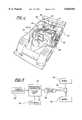
- FIG. 1is a perspective view of a hybrid vehicle.
- FIG. 2is a block diagram of a power train for the hybrid vehicle.
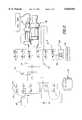
- FIG. 3is a schematic view of the power unit in the vehicle.
- FIG. 4is a perspective view of the power unit.
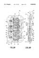
- FIG. 5ais a plan view of a transistor module.
- FIG. 5bis a side view of a transistor module.
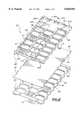
- FIG. 6is an exploded view of the heat exchanger and AC bus.
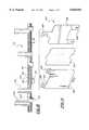
- FIG. 7is an exploded view of the DC bus.
- FIG. 8is a cross sectional view of the assembled DC bus.
- FIG. 9is an exploded view of the DC cross strap.
- FIG. 10is a perspective view of the cross ties.
- FIG. 11is a perspective view of the traction motor AC bus.
- FIG. 12is a perspective of the flywheel AC bus.
- FIG. 13is a perspective of the turbine alternator AC bus.
- a hybrid powertrain systemis illustrated for an automotive vehicle 20.
- the vehicle 20is partially shown in a cut away view illustrating a hybrid powertrain system 22 disposed within the chassis 24.
- the hybrid powertrain system 22includes a gas powered turbine engine 26, which in this example is fueled by liquefied natural gas.
- the turbine engine 26spins an alternator unit 28 to generate electric power.
- alternator unit 28it should be appreciated that in this example there are two alternators in the alternator unit 28 that run at different speeds, such as 60,000 rpm and 100,000 rpm, to produce electricity equivalent to 500 horsepower.
- a flywheel 40is provided for energy storage.
- a traction motor 32receives power to move the vehicle 20.
- a power management controller 30controls power between the alternator unit 28, turbine engine 26, traction motor 32 and flywheel 40.
- the management controller 30is in communication with the turbine engine 26 and alternator unit 28, and manages the distribution of power from the alternator 28 to the traction or induction motor 32 and through a drive train, utilizing a three phase variable frequency alternating current (VFAC).
- VFACvariable frequency alternating current
- the traction motor 32is an AC induction motor.
- the traction motor 32transfers its energy to the drive train 40 to drive the automotive vehicle 20.
- the management controller 30directs the alternator 28 and if necessary a flywheel 40, to supply power to the traction motor 32 which in turn drives the wheels 42. If the power need of the traction motor 32 is low, the management controller 30 directs the excess power capacity into the flywheel 40 for storage.
- the hybrid powertrain system 22also includes various critically placed sensors which are conventional and well known in the art. The outputs of these sensors communicate with the control system 30. It should also be appreciated that the automotive vehicle 20 includes other hardware not shown, but conventional in the art to cooperate with the hybrid powertrain system 20.
- the peripheral machinescomprising the turbine alternator unit 28 and traction motor 32 are all induction machines.
- the flywheel 40is a permanent magnet machine. Power in the form of alternating current must be supplied to each electric machine 28,32,40 and may be generated or provided by each electric machine 28,32,40.
- the management controller 30manipulates the power to form the necessary signals for each electric machine 28,32,40 (i.e., frequency and magnitude) and provides the necessary magnitude changes.
- the system 22also includes a power unit 112 for converting and storing power and transferring same between the electric machines 28,32,40 based on control signals from the management controller 30.
- the power unit 112can transfer power directly between all of the major electric machines 28,32,40 bidirectionaly with the 800 VDC bus as the medium of exchange.
- the 800 V DC busis held constant primarily by absorbing and generating power from and to the flywheel.
- the DC capacitor bankis used to absorb and generate power for the amount of time needed for the flywheel controller to respond and control the DC bus which is approximately 5 milliseconds. For transients longer than 5 milliseconds a combination of the flywheel and the dump resistor circuit is used.
- the bidirectional power to the turbo alternators 28is power that is sent into the alternator 28 from the DC bus through the power transistors to excite the magnetic field required to generate EMF.
- the resultant power flowis out of the generator and is rectified from AC to DC by the diodes 122 in the transistor modules 120 and coupled back 800 VDC bus.
- the bidirectional power flow to the permanent magnet flywheel motoris the power unit 112 acts as a buck regulator (or a step-down regulator) in the motoring mode and a boost regulator (or a step up regulator) in the generator mode since the back EMF of the flywheel motor is fixed proportionally to the flywheel speed.
- the combination of the flywheel motor system and DC capacitor bankform an electromechanical battery or energy accumulator.
- a low power external 800 VDCis connected to the power management system and is used to slow charge the electomechanical battery by storing energy in the flywheel by slowly increasing the flywheel speed.
- the gas turbine engineis started by transferring energy from the flywheel to through the power unit to the alternators which are now used as a inductive drive motor machine to start the turbines.
- the management controller 30manipulates and controls the power unit 112 to selectively transfer the power based on various operating conditions of the vehicle, and to synthesize a sinusoidal current waveform to operate the electric machines 28,32,40 at the desired levels. Alternating current waveforms are constructed from DC stored signals.
- the power unit 112stores DC voltage at a nominal 800V.
- the turbine alternator unit 28requires ac power signals at 1500-2 kHz
- the flywheelrequires AC power signals up to 10 kHz
- the traction motor 32requires AC power signals at 600-700 Hz.
- FIG. 3A schematic diagram of the power unit 112 is generally illustrated in FIG. 3.
- the power unit 112includes a plurality of power switches in the form of power transistors 114 connected between the electric machines 28,32,40 and a DC energy storage assembly in the form of a capacitor bank 116.
- the power transistors 114switch power to each of the electric machines 28,32,40 from the capacitor bank 116, and also switch power from these machines to the capacitor bank 116.
- the capacitor bank 116stores pulsating DC voltage levels at a nominal 800 volts (+ ⁇ -50V.).
- Connected between the capacitor bank 116 and the power transistors 114is a DC bus 118 which communicates the DC power stored in the capacitor banks 116 to and from the power transistors 114.
- the gates of the power transistors 114are controlled such that synthesized AC power signals are sent to each of the electric machines 28,32,40 through pulse width modulation.
- AC power which is produced by the alternator unit 28is rectified by the diodes mounted with power transistors 114 and is supplied to the capacitor bank 116 via the DC bus 118.
- the power transistors 114are comprised of a plurality of insulated gate bipolar transistors (IGBT) which, as commonly known in the art, are a hybrid between a bipolar transistor and a MOSFET wherein an insulated gate receives a voltage controlled signal which controls a large output current flowing through the transistor 114.
- IGBTinsulated gate bipolar transistors
- the transistors 114are part of a transistor module 120 illustrated in FIG. 5a.
- Each transistor module 120is comprised of six separate transistors 114 and twelve diodes 122 connected on a common board forming the module 120.
- the numerous transistors 114 and diodes 122are utilized to share the high current flowing through the power unit 112.
- the transistors 114are each connected to a free wheeling diode 122 across their collector/emitter.
- a dampening resistor 123is connected to the gate 126.
- the transistors 114are connected in an H-bridge configuration to allow the production of three-phase AC signals.
- the H-bridgeis comprised of six transistor modules 120 connected as illustrated in FIG. 3.
- pairs of transistor modules 120 forming one phasehave a common emitter and collector providing or receiving the AC signal at their common collector/emitter point, whereas the other of the emitter and collector of the pair are connected to opposite polarities of the DC bus 118. Therefore, there are three pairs of transistor modules 120 producing the three-phase output signal.
- the gates 126 of the transistors 114are connected to a gate drive assemblies 128, as subsequently discussed.
- the gate drive assemblies 128pulse width modulate the transistors 114 to synthesize the AC waveform by switching the pairs on and off.
- the traction motor 32utilizes eighteen (18) transistor modules 120
- the flywheel 40utilizes twelve (12) transistor modules 120
- the alternator unit 28utilizes twelve (12) transistor modules 120 (six for each alternator).
- the transistor modules 120are connected to a fluid cooled cold-plate, which will be referred to as the heat exchanger assembly 130.
- the direct connection between the transistor modules 120 and the heat exchanger assembly 130provide optimal cooling of the transistors 114 due to the switching and current considerations of the transistor modules 120.
- the transistor modules 120include a support plate 132 which is in direct contact with the cooling fluid of the heat exchanger assembly 130.
- the plate 132is generally rectangular in shape and includes a plurality of cooling fins 134 extending from an outward surface thereof.
- the fins 134extend longitudinally across the surface in the direction of coolant flow across the module 120 i.e., same direction of power flow through the module 120.
- the fins 134provide turbulent flow through the exchanger 130 of the fluid with modest pressure drop but high thermal transfer characteristics.
- An opposing supporting surface 135supports the transistors 114 in thermal contact therewith.
- the support plate 132is preferably made of silicon carbide to enhance cooling conduction and to obtain a thermal coefficient of expansion similar to silicon (that of the transistors 114).
- the silicon carbide plate 132is machined or alternatively cast to form the fins 134 and is over plated with gold.
- An electrical insulation layer 136is connected by solder to the support plate 132.
- the insulation layer 136comprises DBC (direct bond copper) which is formed by a layer of copper, aluminum nitride, and copper heated to melt and fuse the copper to the ceramic substrate.
- the thermal conductivityis high in this layer 136 (similar to aluminum), and the layer 136 can be soldered at the two outer copper surfaces.
- six separate areasare formed by the insulation layer 36 (two for the transistors 114 and four for the contact pads 146).
- the integrated circuit chip (silicon) forming the transistors 114is soldered to the copper surface of the electrical insulation layer 136. Each chip or die 114 represents one transistor operating at 75 Amperes.
- the module 114includes raised contact pad 146 connected to the collectors and emitters of the transistors 114 by suitable wire lead connections 147.
- the contact pads 146are formed of ductile copper strips 148 to allow some bending and flexibility thereof for connection. This will provide suitable connection when the connection surfaces are not coplanar within small tolerances with all of the contact pads 146.
- the strips 148include a resilient bond 150 therein to allow for the extension and retraction of the contact pads 146 to ensure the required electrical contact.
- the strips 148include ends 149 which are soldered to the module 120 on the electrical insulation layer 136.
- the support plate 132includes a plurality of fastening apertures 154 extending therethrough for mounting, as subsequently described.
- each transistor module 120either the collectors or emitters are connected to the DC bus 118 at the contact pads 146 on one side of the module 120.
- the strips 148are connected by the wire leads 147 to the electrically conducting DBC layer 136, and the transistor chip 114 contacts the DC signal on its bottom die surface.
- the heat exchanger assembly 130provides cooling of the transistor modules 120, along with other components of the power unit 112.
- the heat exchanger assembly 130includes a first frame member 160 having a plurality or matrix of open windows 162 therein.
- the windows 162receive the transistor modules 120 in sealed connection therewith.
- a sealing O-ring 164is placed between the support plate 132 of the transistor modules 120 and the window 162.
- Frame walls 163surround the windows 162 and provide a flange to support the O-ring seal 164.
- the heat exchanger assembly 130also includes a base plate 166 connected to the first frame member 160 and spaced therefrom establishing a first cavity to allow water to flow between the base plate 166 and the frame member 160.
- the fluid flowing in the cavitythereby flows through the fins 134 of the transistors modules 114 to aid in cooling thereof.
- the first frame member 160also includes fins 161 extending into the cavity which align with the fins 134 of the transistor modules 120.
- the heat exchanger 130also includes a second frame member 170 opposing the first frame member 160 about the base plate 166 and operatively secured with the base plate 166 and the first frame member 160.
- the second frame member 170is spaced from the base plate 166 to establish a second cavity therebetween for allowing fluid to flow therethrough.
- finsare provided on the interior surface of the frame.
- a fluid inlet 172is connected to either of the first or second frame members 160,170, and a fluid outlet 173 is secured to the other of the first or second frame members 160,170.
- the inlet 172is connected to the first frame member 160
- the outlet 173is connected to the second frame member 170.
- the flowis parallel through the heat exchanger 130.
- the end of the base plate 166 opposite the inlet 172 and outlet 173 endis provided with are fluid openings 171 to allow fluid to flow from the first cavity to the second cavity.
- the frame members 160,170 and base plate 166are generally rectangular in shape.
- the perimeter of the frame members 160,170 and base plate 166include a plurality of fastening apertures 174 therethrough for receiving suitable fasteners 175 for connecting the frame members 160,170 and base plate 166 to one another.
- each of the first and second frame members 160,170include a plurality of support posts 178 extending outwardly from the cross points of the frame walls 163 between the corners of adjacent windows 162.
- the support posts 178are for mounting in the DC bus 118, as discussed subsequently.
- mounting apertures 179extending into the outer edge of the perimeter wall of the base plate 166 for mounting the heat exchanger 130 to a chassis housing 300, as subsequently discussed.
- the windows 162are formed in a matrix pattern within each of the frame members 160,170.
- the matrixis formed by 3 ⁇ 8 windows.
- the first frame member 160includes a mounting plate 176 connected in place of five (5) of the windows 162 to allow for mounting and cooling of additional components other than the transistor modules 114.
- the windows 162are formed in the remainder of the first frame member 160. All of the matrix is comprised of windows 162 in the second frame member 170.
- the transistor modules 120are mounted to each of the frame members 160 with the contact pads 146 extending outwardly from the heat exchanger assembly 130. Therefore, the transistor modules 120 are loaded from the cavity side of the frame members 160,170 with the O-ring seals 164 therebetween. Fasteners connect the transistor modules 114 to the frame members 160,170.
- the second frame member 170holds twenty-four (24) transistor modules 120
- the first frame member 160holds eighteen (18) transistors modules 120.
- a remainder of the windows 162 not filled by a transistor module 120is utilized for a dump resistor 182, which is used for dumping power over a predetermined limit from the DC bus 118.
- the DC bus 118comprises two DC buses 118a,118b identically formed and each including a positive and negative half. Therefore, the general structure of the DC bus 118 will be described, it being understood that it is applied to both separate buses 118a,118b.
- the DC bus 118includes a first conducting plate 190 and a second conducting plate 191.
- An insulation layer 192is sandwiched between the two plates 190,191.
- the plates 190,191 and the insulation layer 192are laminated to one another forming a thin conducting plane.
- the first conducting plate 190forms the positive DC signal and the second conducting plate 91 forms the negative or reference DC signal.
- Each of the first and second conducting plates 190,191include fluid passages 194 extending within the plates 190,191 allowing fluid to circulate therein for cooling purposes.
- Each of the plates 190,191include a fluid inlet 195 and a fluid outlet 196 extending longitudinally outwardly from opposite ends of the plates 190,191 and along a common side thereof.
- the bus fluid inlets 195 for both plates 190,191are both on one end of the buss 118 and the bus fluid outlets 196 are on an opposing end of the bus 118 for allowing coolant or water to be pumped therethrough.
- the inlet/outlet pair 195,196 on the first plate 190is on an opposing side from the pair 195,196 of the second plate 191 (see FIG. 7).
- Each of the plates 190,191is formed by first and second conducting sheets 198,199 with a corrugated material 200 therebetween.
- the sheets 198,199 and corrugated sheet material 200are brazed sealed to one another forming an enclosed cavity to allow the fluid to pass therethrough.
- An aluminum materialis utilized for each of the sheets 198,199 and corrugated sheet 200.
- the flow through the plates 190,191is in a serpentine manner with longitudinal openings 202 in each plate 190,191 separating each channel and change in direction of flow.
- the corners 204 in serpentine flow patternare provided by 45° straight channels as illustrated in FIG. 7.
- the bus inlets 195,196are connected to the heat exchanger 130 to receive fluid flow.
- the heat exchanger 130includes a pair of elongated fluid openings 206 near the outer corners of the first frame 160 and at the same end as the exchanger inlet 172 to pump coolant to the inlets 195 of the bus plates 190,191 of the upper DC bus 118a.
- the heat exchanger 130includes a second pair of elongated openings 208 near the outer corners of the first frame 160 at the end opposite the exchanger inlet 172 to receives the return flow of fluid from the upper DC bus 118a.
- the second frame 170 of the heat exchangerincludes pairs of elongated openings 210 for supplying and circulating fluid through the lower DC bus 118b. Therefore, a single fluid inlet and outlet to the heat exchanger 130 provides circulating cooling fluid for both the heat exchanger 130 and the DC bus 118.
- the first and second conducting plates 190,191include a plurality of longitudinal openings 202 extending between the serpentine fluid flow paths. There are provided parallel rows of the openings 202.
- the DC bus 118is provided to allow direct contact to the transistor modules 120 on a first side thereof and direct contact to the capacitor banks 116 on the second side thereof. In both cases, both positive and negative side contacts 212,214 must be provided to each of the surfaces, i.e. to each of the capacitors 116 and to each of the transistor modules 120.
- the openingsallow for contacts from one plate to extend through the other plate, and vise versa.
- Each of the conducting plates 190,191include a plurality of contact posts 212,214 extending on both first and second sides of the plates 190,191 and perpendicular therewith.
- the contacts 214 extending on the side of the plates 190,191 adjacent the insulation layer 192are positioned in the openings 202 of the other of the plates 190,191. Therefore, when viewing a first side of the first conducting plate 190 (See FIG. 7), the plate 190 includes contacts 212 extending outwardly from the surface, and within the openings provided in the plate 190 are extended opposite polarity contact posts 214 through the insulation layer 192 from the second conducting plate 191.
- the outer surface of the second conducting plate 191is also similarly oriented with the positive and negative conducting posts 212,214 both extending on one side.
- the positioning of the contact posts 212,214depends on the positioning of the transistor modules 120 and the brackets for holding the capacitor banks 116. It can be appreciated that both the positive and negative DC signals are required off both outward surfaces of the DC buses 118a,118b. Both DC buses 118a,118b are similarly formed, with the geometry or positioning of the contact posts 212,214 varying depending on necessary connections.
- the plates 190,191include a plurality of holes 216 formed therein and extending through the buses 118a,118b to be aligned with the connection posts 178 of the cross points on the heat exchanger 130.
- the heat exchanger 130 and the DC buses 118a,118bare mounted to one another for structural ridgity at these holes by suitable fasteners.
- the longitudinal side edges of the DC bus 118i.e. each of the plates 190,191, include contact pads 218,220 formed therein.
- the perpendicular contact pads 218,220are perpendicular to the plane of the DC bus. These contact pads 218,220 allow for interconnection between the two buses 118a,118b, as subsequently discussed.
- the first and second bus members 118a,118bare spaced from one another about the heat exchanger 130.
- a plurality of conducting strap members 222interconnect the first and second buses 118a,118b.
- the conducting strap members 222include first and second strap plates 223,224 electrically insulated from one another and secured to one another.
- a first of the strap plates 223is connected to the positive bus plates 190 and a second of the strap plates 224 is connected to the negative bus plates 191.
- the strap plates 223,224are comprised of generally planar, wide thin sheets sandwiched against one another.
- An insulation sheet 225 of materialis provided and laminated between the strap plates 223,224 to isolate the opposite polarity signal on the plates 223,224.
- the strap plates 223,224include first and second ends.
- the first and second endsinclude planar contact pads 226,228 extending outwardly from each end.
- the contact pads 226 of the first plate 223include a shoulder 227 formed therein off set from the plate so that the contact pads 226 of the first and second plates 223,224 are coplanar when assembled.
- the contact pads 226,228are fixedly connected to the perpendicular contact pads 218,220 extending from the two bus members 118a,118b. This allows current to flow through the strap members 222 to each of the bus members 118.
- the strap members 222are comprised of sheet aluminum material coated on their outer surface by a gold layer to increase conductivity.
- the strap members 222are symmetrical.
- the bus members 118 and straps 222are laminated to keep the inductance of the bus system at a minimum. This keeps the voltage spikes during switching low. It also allows a reduction of capacitance required to stabilize the bus 118.
- the power unit 112includes cross ties 230 as illustrated in FIG. 10.
- the cross tiesare comprised of an aluminum sheet of material cut out to have four (4) symmetrical arms 232 extending therefrom with outer ends of the each arm 232 including a mounting aperture 233 and the center point of the cross tie includes a mounting aperture 234.
- there are two (2) transistor modules 120which form one third of the H-bridge which drive the induction machines in three phase. As illustrated in FIG. 3, each pair of transistors have a common emitter and collector connected to one another.
- the cross ties 230form this interconnection as illustrated.
- Each of the modules 120forms 1/6 of the H-bridge and is connected to its pair.
- all of the collectors of transistor module 120aare connected to all of the emitters of transistor module 120b by the cross tie 230 to provide a single out put at center aperture 234 of one phase of the ac signal.
- the cross ties 230are constructed of an aluminum material with gold plating as with the DC strap plates 222.
- the turbine alternatorrequires a single pair of transistor modules 120 for each phase as is illustrated in the drawings, i.e., six transistor modules 120.
- the flywheelrequires two (2) layers of the H-bridge transistors modules 120 for each transistor illustrated in the FIG. 3. Therefore, four (4) transistor modules 120 are used to drive one phase.
- the traction motorthere are three (3) transistor modules 120 for each transistor illustrated in FIG. 3.
- six (6) transistor modules 120drive one phase of the traction motor.
- the amount of transistor modules 120 usedis due to current requirements of the machines.
- the ac bus barsinclude a bus bar assembly for each electric machine 28,32,40.
- the bus bar assembliescontact the respective cross ties 230 and communicate the ac signals to the respective electric machines 28,32,40.
- Each bus bar assemblyincludes one bus bar for each phase of the three phase signal.
- the traction motor bus bar assembly 240contacts three (3) cross ties in order to produce one phase of the ac signal to the traction motor 32. This is accomplished by using a pair of connecting plates 242,243.
- a first plate 242includes three apertures 244 for connection with three cross ties 230.
- the first plate 242includes a pair of center intermediate apertures 246 equally spaced between the three 244.
- a second plate 243is electrically insulated from the first plate by an insulation layer 248, except at the intermediate apertures 246 which conduct the signal from the first plate 242 to the second plate 243.
- the second plate 243includes a center connecting output aperture 250 to provide the single phase ac signal.
- a transmitting bus bar 252connects at the center point 250 of the second plate 243 to connect the signal directly to the traction motor 32.
- the cross strapping shown in FIG. 11is to equalize the length of the individual phases.
- flywheelthere are two (2) layers of the transistors 120 for each illustrated in the general FIG. 3. Therefore, there are two (2) cross ties 230 which are interconnected by a first layer AC bus bar 254 to provide one phase of the ac signal driving the flywheel 40.
- a transmitting bus bar 256connects the first layer bus bar to the flywheel 40.
- the ac bus bar 260contacts a single cross tie 230 to provide a single phase of AC power.
- a single bus bar 261 for each phaseis used and connected only to a single cross tie 230. Therefore, three bus bars 261 are utilized to drive one of the turbine alternators 28 for a three phase signal.
- the intermediate bus barsare comprised of a single bar with geometry to evenly pull signals from each cross tie 230 contact.
- Each of the transmitting bus bars 252,256,260are comprised of multi layer sheets of bars stacked on each other (See FIG. 11) and laminated and having the same geometry and distance for each layer to insure symmetry of the signal.
- five (5) barsare utilized to provide the AC transmitting bus for a single signal for the flywheel 36 and traction motor 32. This allows 700 Amps to be transmitted.
- Each of the frequencies at which the AC signal is operatedskin effect occurs whereby the signal is carried on the outside surface of the conductor. Therefore, by using a plurality of sheets of bars, higher signal levels and signal response may be obtained.
- Each of the bars comprising a busis laminated together to provide a single unit.
- the turbine alternator 28uses single layer of bar.
- the geometry of the AC bus barsis dependent upon space requirements within the power unit. In general, it is preferred to optimize width of the bars and shortness in distance to the driver machine.
- the capacitor banks 116are connected on the outer sides of the both of the DC buses 118a,118b, i.e., there are two (2) capacitor banks 116a,116b.
- Each capacitor 270is a metalized poly propylene film capacitor with low dissipation factor; each can carry 30 Amps and are 23 mF.
- the capacitor banks 116are comprised of a plurality of cylindrically shaped capacitors 270 mounted to a plurality of mounting bracket 270 connected to the DC buses 118a,118b.
- the positive and negative contact posts 212,214 extending from the DC bus 118a,118bare connected to the L-shaped brackets 272.
- the base 273 of the L-shaped bracketis connected to the respective of the DC bus control posts 212,214 wherein the perpendicular extending side includes apertures 274 therein to receive ends of the capacitors 270.
- a pair of brackets 272is laminated to each other with an insulation layer 276 therebetween.
- One of the brackets 272bconnects to the negative DC bus plate 191 and the other of the brackets 272 connects to the positive DC bus plate 190.
- Each capacitor 270is connected between positive and negative brackets 272.
- a pair of brackets 272is connected between rows of capacitors 270 wherein one of the brackets 272a is positive and one of the brackets 272b is negative.
- capacitors 270On the upper side of the power unit 112 there are connected forty-eight (48) capacitors 270 between multiple pairs of the capacitor brackets 272. On the lower capacitor bank 116b there are connected twenty-four (24) capacitors 270 in a staggered arrangement. In design, the capacitance is made to be maximized with consideration of the space available. Therefore, more capacitors 270 could be used if more space was available.
- the gate drivers 128Connected to the outer sides of the capacitor banks 116a,116b are the gate drivers 128. There is one gate driver 128 for each transistor module 120.
- the gate driver 128is comprised of a circuit board 280 with appropriate conductors and circuitry thereon.
- the gate drivers 128receive a control signal from the management controller 30 to drive the transistors 114 at the established pulse width modulation to output the ac signals.
- the gate drivers 128are positioned in three rows on the outside and a center row within the upper capacitor bank 116a, and on the bottom of the lower capacitor bank 116b. Positioning is merely for compact space requirements and to situate the drivers as close to its respective transistor module 120 as possible.
- Each of the leads from the gate drivers 128is approximately three (3) to four (4) inches long and connected to its respective transistor module 120. It is important that the conduction length be equivalent for each gate driver to ensure proper firing of the respective transistor module 120.
- the power unit 112includes a housing 282 for supporting each of the internal components.
- the housing 282is provided as an integrated unit when assembled with the power unit 112 and management controller 30 which may be simply placed as a whole unit in the vehicle 20 and removed therefrom.
- the housing 282includes two opposing longitudinal side walls 283,284 having fastening openings 285 extending along the center thereof along the longitudinal length.
- the fastening openings 285receives fasteners which are connected to the mounting apertures 179 on the heat exchanger 130.
- the housing 282also includes an integrally connected end wall 286 providing outputs connections at a first end.
- a second end wall 287 opposing the first end wallprovides additional output and input connections.
- a divider wall 288is secured and positioned within the housing 282 to section off a part of the internal housing for the management controller 30 for EMI/RFI protection of the controller 30.
Landscapes
- Engineering & Computer Science (AREA)
- Transportation (AREA)
- Mechanical Engineering (AREA)
- Power Engineering (AREA)
- Chemical & Material Sciences (AREA)
- Combustion & Propulsion (AREA)
- Microelectronics & Electronic Packaging (AREA)
- Electric Propulsion And Braking For Vehicles (AREA)
Abstract
Description
Claims (6)
Priority Applications (1)
| Application Number | Priority Date | Filing Date | Title |
|---|---|---|---|
| US08/641,926US5828554A (en) | 1996-05-02 | 1996-05-02 | Integrated chassis, enclosure and cage |
Applications Claiming Priority (1)
| Application Number | Priority Date | Filing Date | Title |
|---|---|---|---|
| US08/641,926US5828554A (en) | 1996-05-02 | 1996-05-02 | Integrated chassis, enclosure and cage |
Publications (1)
| Publication Number | Publication Date |
|---|---|
| US5828554Atrue US5828554A (en) | 1998-10-27 |
Family
ID=24574441
Family Applications (1)
| Application Number | Title | Priority Date | Filing Date |
|---|---|---|---|
| US08/641,926Expired - LifetimeUS5828554A (en) | 1996-05-02 | 1996-05-02 | Integrated chassis, enclosure and cage |
Country Status (1)
| Country | Link |
|---|---|
| US (1) | US5828554A (en) |
Cited By (47)
| Publication number | Priority date | Publication date | Assignee | Title |
|---|---|---|---|---|
| US5920463A (en)* | 1997-10-17 | 1999-07-06 | Robert Bosch Gmbh | Component mounting device for an electrical controller |
| US20020171138A1 (en)* | 2001-05-21 | 2002-11-21 | Yasuo Osone | Multilayer wiring board and semiconductor device |
| US20040062005A1 (en)* | 2002-09-27 | 2004-04-01 | Pfeifer David W. | Compact liquid converter assembly |
| US20040062006A1 (en)* | 2002-09-27 | 2004-04-01 | Pfeifer David W. | Laminated bus bar for use with a power conversion configuration |
| US20040060689A1 (en)* | 2002-09-27 | 2004-04-01 | Pfeifer David W. | Compact liquid cooled heat sink |
| US20040062004A1 (en)* | 2002-09-27 | 2004-04-01 | Pfeifer David W. | Bus bar assembly for use with a compact power conversion assembly |
| US6757597B2 (en) | 2001-01-31 | 2004-06-29 | Oshkosh Truck | A/C bus assembly for electronic traction vehicle |
| US20040222757A1 (en)* | 2003-03-13 | 2004-11-11 | Tsutomu Inui | Hybrid type working machine |
| US6885920B2 (en) | 1999-07-30 | 2005-04-26 | Oshkosh Truck Corporation | Control system and method for electric vehicle |
| US20050161275A1 (en)* | 2004-01-23 | 2005-07-28 | Philippe Serrano | Structure and method for mounting equipment inside vehicles |
| US20060002054A1 (en)* | 2004-07-02 | 2006-01-05 | Visteon Global Technologies, Inc. | Electric machine with integrated electronics in a circular/closed-loop arrangement |
| US20060007720A1 (en)* | 2002-09-27 | 2006-01-12 | Pfeifer David W | Compact liquid converter assembly |
| US20060010844A1 (en)* | 2004-06-30 | 2006-01-19 | Self Guided Systems, L.L.C. | Unmanned utility vehicle |
| US20060059880A1 (en)* | 2004-09-13 | 2006-03-23 | Angott Paul G | Unmanned utility vehicle |
| US20060125238A1 (en)* | 2004-11-03 | 2006-06-15 | Santosh Sinha | Automatic power connector system machine |
| US7254468B2 (en) | 2001-12-21 | 2007-08-07 | Oshkosh Truck Corporation | Multi-network control system for a vehicle |
| US7302320B2 (en) | 2001-12-21 | 2007-11-27 | Oshkosh Truck Corporation | Failure mode operation for an electric vehicle |
| US7332881B2 (en) | 2004-10-28 | 2008-02-19 | Textron Inc. | AC drive system for electrically operated vehicle |
| US7379797B2 (en) | 2001-01-31 | 2008-05-27 | Oshkosh Truck Corporation | System and method for braking in an electric vehicle |
| US7439711B2 (en) | 2004-09-27 | 2008-10-21 | Oshkosh Corporation | Energy storage device including a status indicator |
| US7520354B2 (en) | 2002-05-02 | 2009-04-21 | Oshkosh Truck Corporation | Hybrid vehicle with combustion engine/electric motor drive |
| US7711460B2 (en) | 2001-01-31 | 2010-05-04 | Oshkosh Corporation | Control system and method for electric vehicle |
| US20100128437A1 (en)* | 2008-10-24 | 2010-05-27 | C.R.F. Societa Consortile Per Azioni | Automotive inverter assembly |
| US20100165575A1 (en)* | 2008-12-31 | 2010-07-01 | Caterpillar Inc. | Electronics component packaging for power converter |
| US20100232111A1 (en)* | 2009-03-11 | 2010-09-16 | Caterpillar Inc. | Power Converter |
| US20100285702A1 (en)* | 2007-12-28 | 2010-11-11 | Clean Current Power Systems Incorporated | Hybrid electric power system with distributed segmented generator/motor |
| US7835838B2 (en) | 1999-07-30 | 2010-11-16 | Oshkosh Corporation | Concrete placement vehicle control system and method |
| US20110012422A1 (en)* | 2009-07-14 | 2011-01-20 | Wabtec Holding Corp. | Power Generation and Distribution System Configured to Provide Power to a Motor |
| US7926889B2 (en) | 2007-10-29 | 2011-04-19 | Textron Innovations Inc. | Hill hold for an electric vehicle |
| US8139109B2 (en) | 2006-06-19 | 2012-03-20 | Oshkosh Corporation | Vision system for an autonomous vehicle |
| US8235732B2 (en) | 2008-05-15 | 2012-08-07 | Johnson Controls—SAFT Advanced Power Solutions LLC | Battery system |
| ITBO20110274A1 (en)* | 2011-05-16 | 2012-11-17 | Giben Int Spa | CUTTING MACHINE |
| US8337352B2 (en) | 2010-06-22 | 2012-12-25 | Oshkosh Corporation | Electromechanical variable transmission |
| US8947531B2 (en) | 2006-06-19 | 2015-02-03 | Oshkosh Corporation | Vehicle diagnostics based on information communicated between vehicles |
| US9114804B1 (en) | 2013-03-14 | 2015-08-25 | Oshkosh Defense, Llc | Vehicle drive and method with electromechanical variable transmission |
| US20150292304A1 (en)* | 2011-10-06 | 2015-10-15 | Siemens Aktiengesellschaft | Power Cell for Deepwater Application |
| US9651120B2 (en) | 2015-02-17 | 2017-05-16 | Oshkosh Corporation | Multi-mode electromechanical variable transmission |
| US9650032B2 (en) | 2015-02-17 | 2017-05-16 | Oshkosh Corporation | Multi-mode electromechanical variable transmission |
| US9656659B2 (en) | 2015-02-17 | 2017-05-23 | Oshkosh Corporation | Multi-mode electromechanical variable transmission |
| US10421350B2 (en) | 2015-10-20 | 2019-09-24 | Oshkosh Corporation | Inline electromechanical variable transmission system |
| US10536038B1 (en)* | 2018-07-30 | 2020-01-14 | Honda Motor Co., Ltd. | System for harvesting energy for a vehicle |
| US10578195B2 (en) | 2015-02-17 | 2020-03-03 | Oshkosh Corporation | Inline electromechanical variable transmission system |
| US10584775B2 (en) | 2015-02-17 | 2020-03-10 | Oshkosh Corporation | Inline electromechanical variable transmission system |
| US10982736B2 (en) | 2015-02-17 | 2021-04-20 | Oshkosh Corporation | Multi-mode electromechanical variable transmission |
| US11701959B2 (en) | 2015-02-17 | 2023-07-18 | Oshkosh Corporation | Inline electromechanical variable transmission system |
| US20240190236A1 (en)* | 2021-04-12 | 2024-06-13 | Morand Cars Sa | Architecture for a hybrid vehicle |
| US12078231B2 (en) | 2015-02-17 | 2024-09-03 | Oshkosh Corporation | Inline electromechanical variable transmission system |
Citations (20)
| Publication number | Priority date | Publication date | Assignee | Title |
|---|---|---|---|---|
| US4444285A (en)* | 1981-07-30 | 1984-04-24 | Stewart Charles F | Electro-mechanical propulsion system |
| US4495451A (en)* | 1981-01-06 | 1985-01-22 | Barnard Maxwell K | Inertial energy interchange system with energy makeup by combustion engine on demand |
| US4533011A (en)* | 1979-10-27 | 1985-08-06 | Volkswagenwerk Aktiengesellschaft | Hybrid drive for a vehicle, in particular an automobile |
| US4631456A (en)* | 1982-03-22 | 1986-12-23 | The Charles Stark Draper Laboratory, Inc. | Inertial energy storage device and synchronous rotary electrical machine for use therein |
| US4900962A (en)* | 1989-01-18 | 1990-02-13 | Satcon Technology Corporation | Magnetic translator bearings |
| US4961352A (en)* | 1988-02-24 | 1990-10-09 | Satcon Technology Corporation | Magnetic bearing and suspension system |
| US5060112A (en)* | 1990-04-02 | 1991-10-22 | Cocconi Alan G | Electrical component assembly with heat sink |
| US5172784A (en)* | 1991-04-19 | 1992-12-22 | Varela Jr Arthur A | Hybrid electric propulsion system |
| US5255733A (en)* | 1992-08-10 | 1993-10-26 | Ford Motor Company | Hybird vehicle cooling system |
| US5291975A (en)* | 1992-10-27 | 1994-03-08 | Satcon Technology Corporation | System and method for damping narrow band axial vibrations of a rotating device |
| US5319273A (en)* | 1992-10-26 | 1994-06-07 | Satcon Technology Corporation | Fixed gain electromagnetic actuator and electromagnetic bearing incorporating same |
| US5318142A (en)* | 1992-11-05 | 1994-06-07 | Ford Motor Company | Hybrid drive system |
| US5327987A (en)* | 1992-04-02 | 1994-07-12 | Abdelmalek Fawzy T | High efficiency hybrid car with gasoline engine, and electric battery powered motor |
| US5345761A (en)* | 1993-12-02 | 1994-09-13 | Ford Motor Company | Energy management system for hybrid vehicle |
| US5353656A (en)* | 1992-08-18 | 1994-10-11 | Satcon Technology Corporation | Electrostatically controlled micromechanical gyroscope |
| US5396140A (en)* | 1993-05-28 | 1995-03-07 | Satcon Technology, Corp. | Parallel air gap serial flux A.C. electrical machine |
| US5442288A (en)* | 1993-04-22 | 1995-08-15 | Satcon Technology Corporation | Magnetoelastic magnetometer |
| US5465015A (en)* | 1993-09-24 | 1995-11-07 | Satcon Technology Corporation | Transverse field activated magnetostrictive motor |
| US5504378A (en)* | 1994-06-10 | 1996-04-02 | Westinghouse Electric Corp. | Direct cooled switching module for electric vehicle propulsion system |
| US5504655A (en)* | 1994-06-10 | 1996-04-02 | Westinghouse Electric Corp. | Electric vehicle power distribution module |
- 1996
- 1996-05-02USUS08/641,926patent/US5828554A/ennot_activeExpired - Lifetime
Patent Citations (20)
| Publication number | Priority date | Publication date | Assignee | Title |
|---|---|---|---|---|
| US4533011A (en)* | 1979-10-27 | 1985-08-06 | Volkswagenwerk Aktiengesellschaft | Hybrid drive for a vehicle, in particular an automobile |
| US4495451A (en)* | 1981-01-06 | 1985-01-22 | Barnard Maxwell K | Inertial energy interchange system with energy makeup by combustion engine on demand |
| US4444285A (en)* | 1981-07-30 | 1984-04-24 | Stewart Charles F | Electro-mechanical propulsion system |
| US4631456A (en)* | 1982-03-22 | 1986-12-23 | The Charles Stark Draper Laboratory, Inc. | Inertial energy storage device and synchronous rotary electrical machine for use therein |
| US4961352A (en)* | 1988-02-24 | 1990-10-09 | Satcon Technology Corporation | Magnetic bearing and suspension system |
| US4900962A (en)* | 1989-01-18 | 1990-02-13 | Satcon Technology Corporation | Magnetic translator bearings |
| US5060112A (en)* | 1990-04-02 | 1991-10-22 | Cocconi Alan G | Electrical component assembly with heat sink |
| US5172784A (en)* | 1991-04-19 | 1992-12-22 | Varela Jr Arthur A | Hybrid electric propulsion system |
| US5327987A (en)* | 1992-04-02 | 1994-07-12 | Abdelmalek Fawzy T | High efficiency hybrid car with gasoline engine, and electric battery powered motor |
| US5255733A (en)* | 1992-08-10 | 1993-10-26 | Ford Motor Company | Hybird vehicle cooling system |
| US5353656A (en)* | 1992-08-18 | 1994-10-11 | Satcon Technology Corporation | Electrostatically controlled micromechanical gyroscope |
| US5319273A (en)* | 1992-10-26 | 1994-06-07 | Satcon Technology Corporation | Fixed gain electromagnetic actuator and electromagnetic bearing incorporating same |
| US5291975A (en)* | 1992-10-27 | 1994-03-08 | Satcon Technology Corporation | System and method for damping narrow band axial vibrations of a rotating device |
| US5318142A (en)* | 1992-11-05 | 1994-06-07 | Ford Motor Company | Hybrid drive system |
| US5442288A (en)* | 1993-04-22 | 1995-08-15 | Satcon Technology Corporation | Magnetoelastic magnetometer |
| US5396140A (en)* | 1993-05-28 | 1995-03-07 | Satcon Technology, Corp. | Parallel air gap serial flux A.C. electrical machine |
| US5465015A (en)* | 1993-09-24 | 1995-11-07 | Satcon Technology Corporation | Transverse field activated magnetostrictive motor |
| US5345761A (en)* | 1993-12-02 | 1994-09-13 | Ford Motor Company | Energy management system for hybrid vehicle |
| US5504378A (en)* | 1994-06-10 | 1996-04-02 | Westinghouse Electric Corp. | Direct cooled switching module for electric vehicle propulsion system |
| US5504655A (en)* | 1994-06-10 | 1996-04-02 | Westinghouse Electric Corp. | Electric vehicle power distribution module |
Non-Patent Citations (2)
| Title |
|---|
| NASA Tech Briefs, The Digest of New Technology, Jun. 1995, vol. 19, No. 6, pp. 12 and 13.* |
| Popular Science Magazine, Emerging Technologies for the Supercar, Jun. 1994.* |
Cited By (95)
| Publication number | Priority date | Publication date | Assignee | Title |
|---|---|---|---|---|
| US5920463A (en)* | 1997-10-17 | 1999-07-06 | Robert Bosch Gmbh | Component mounting device for an electrical controller |
| US6885920B2 (en) | 1999-07-30 | 2005-04-26 | Oshkosh Truck Corporation | Control system and method for electric vehicle |
| US7835838B2 (en) | 1999-07-30 | 2010-11-16 | Oshkosh Corporation | Concrete placement vehicle control system and method |
| US7848857B2 (en) | 2001-01-31 | 2010-12-07 | Oshkosh Corporation | System and method for braking in an electric vehicle |
| US7711460B2 (en) | 2001-01-31 | 2010-05-04 | Oshkosh Corporation | Control system and method for electric vehicle |
| US6757597B2 (en) | 2001-01-31 | 2004-06-29 | Oshkosh Truck | A/C bus assembly for electronic traction vehicle |
| US7379797B2 (en) | 2001-01-31 | 2008-05-27 | Oshkosh Truck Corporation | System and method for braking in an electric vehicle |
| US7164977B2 (en) | 2001-01-31 | 2007-01-16 | Oshkosh Truck Corporation | A/C bus assembly for electronic traction vehicle |
| US20020171138A1 (en)* | 2001-05-21 | 2002-11-21 | Yasuo Osone | Multilayer wiring board and semiconductor device |
| US8000850B2 (en) | 2001-12-21 | 2011-08-16 | Oshkosh Truck Corporation | Failure mode operation for an electric vehicle |
| US7302320B2 (en) | 2001-12-21 | 2007-11-27 | Oshkosh Truck Corporation | Failure mode operation for an electric vehicle |
| US7254468B2 (en) | 2001-12-21 | 2007-08-07 | Oshkosh Truck Corporation | Multi-network control system for a vehicle |
| US7520354B2 (en) | 2002-05-02 | 2009-04-21 | Oshkosh Truck Corporation | Hybrid vehicle with combustion engine/electric motor drive |
| US6885553B2 (en) | 2002-09-27 | 2005-04-26 | Rockwell Automation Technologies, Inc. | Bus bar assembly for use with a compact power conversion assembly |
| US20040062004A1 (en)* | 2002-09-27 | 2004-04-01 | Pfeifer David W. | Bus bar assembly for use with a compact power conversion assembly |
| US20060007720A1 (en)* | 2002-09-27 | 2006-01-12 | Pfeifer David W | Compact liquid converter assembly |
| US20040062005A1 (en)* | 2002-09-27 | 2004-04-01 | Pfeifer David W. | Compact liquid converter assembly |
| US20040062006A1 (en)* | 2002-09-27 | 2004-04-01 | Pfeifer David W. | Laminated bus bar for use with a power conversion configuration |
| US20040060689A1 (en)* | 2002-09-27 | 2004-04-01 | Pfeifer David W. | Compact liquid cooled heat sink |
| US7068507B2 (en) | 2002-09-27 | 2006-06-27 | Rockwell Automation Technologies, Inc. | Compact liquid converter assembly |
| US6956742B2 (en) | 2002-09-27 | 2005-10-18 | Rockwell Automation Technologies, Inc. | Compact liquid converter assembly |
| US6822850B2 (en)* | 2002-09-27 | 2004-11-23 | Rockwell Automation Technologies, Inc. | Laminated bus bar for use with a power conversion configuration |
| US20040222757A1 (en)* | 2003-03-13 | 2004-11-11 | Tsutomu Inui | Hybrid type working machine |
| US6949898B2 (en)* | 2003-03-13 | 2005-09-27 | Honda Motor Co., Ltd | Hybrid type working machine |
| US20050161275A1 (en)* | 2004-01-23 | 2005-07-28 | Philippe Serrano | Structure and method for mounting equipment inside vehicles |
| US20060010844A1 (en)* | 2004-06-30 | 2006-01-19 | Self Guided Systems, L.L.C. | Unmanned utility vehicle |
| US7180212B2 (en) | 2004-07-02 | 2007-02-20 | Visteon Global Technologies, Inc. | Electric machine with integrated electronics in a circular/closed-loop arrangement |
| US20060002054A1 (en)* | 2004-07-02 | 2006-01-05 | Visteon Global Technologies, Inc. | Electric machine with integrated electronics in a circular/closed-loop arrangement |
| US20060059880A1 (en)* | 2004-09-13 | 2006-03-23 | Angott Paul G | Unmanned utility vehicle |
| US7439711B2 (en) | 2004-09-27 | 2008-10-21 | Oshkosh Corporation | Energy storage device including a status indicator |
| US7560882B2 (en) | 2004-10-28 | 2009-07-14 | Textron Inc. | AC drive system for electrically operated vehicle |
| US8120291B2 (en) | 2004-10-28 | 2012-02-21 | Textron Innovations Inc. | Drive system for electrically operated vehicle |
| US7825616B2 (en) | 2004-10-28 | 2010-11-02 | Textron Innovations Inc. | AC drive system for electrically operated vehicle |
| US20110106357A1 (en)* | 2004-10-28 | 2011-05-05 | Textron Inc. | Drive System For Electrically Operated Vehicle |
| US7332881B2 (en) | 2004-10-28 | 2008-02-19 | Textron Inc. | AC drive system for electrically operated vehicle |
| US20060125238A1 (en)* | 2004-11-03 | 2006-06-15 | Santosh Sinha | Automatic power connector system machine |
| US8139109B2 (en) | 2006-06-19 | 2012-03-20 | Oshkosh Corporation | Vision system for an autonomous vehicle |
| US9420203B2 (en) | 2006-06-19 | 2016-08-16 | Oshkosh Defense, Llc | Vision system for a vehicle |
| US8947531B2 (en) | 2006-06-19 | 2015-02-03 | Oshkosh Corporation | Vehicle diagnostics based on information communicated between vehicles |
| US8201897B2 (en) | 2007-10-29 | 2012-06-19 | Textron Inc. | Hill hold for an electric vehicle |
| US7926889B2 (en) | 2007-10-29 | 2011-04-19 | Textron Innovations Inc. | Hill hold for an electric vehicle |
| US20110172869A1 (en)* | 2007-10-29 | 2011-07-14 | Textron Inc. | Hill Hold For An Electric Vehicle |
| US20100285702A1 (en)* | 2007-12-28 | 2010-11-11 | Clean Current Power Systems Incorporated | Hybrid electric power system with distributed segmented generator/motor |
| US8358046B2 (en) | 2007-12-28 | 2013-01-22 | Platon Mihai C | Hybrid electric power system with distributed segmented generator/motor |
| US8235732B2 (en) | 2008-05-15 | 2012-08-07 | Johnson Controls—SAFT Advanced Power Solutions LLC | Battery system |
| US20100128437A1 (en)* | 2008-10-24 | 2010-05-27 | C.R.F. Societa Consortile Per Azioni | Automotive inverter assembly |
| US8072758B2 (en)* | 2008-10-24 | 2011-12-06 | C.R.F. Societa Consortile Per Azioni | Automotive inverter assembly |
| US7869208B2 (en) | 2008-12-31 | 2011-01-11 | Caterpillar Inc | Electronics component packaging for power converter |
| US20100165575A1 (en)* | 2008-12-31 | 2010-07-01 | Caterpillar Inc. | Electronics component packaging for power converter |
| US20100232111A1 (en)* | 2009-03-11 | 2010-09-16 | Caterpillar Inc. | Power Converter |
| US8441827B2 (en)* | 2009-03-11 | 2013-05-14 | Caterpillar Inc. | Power converter assembly having a housing |
| US8102077B2 (en)* | 2009-07-14 | 2012-01-24 | Wabtec Holding Corp. | Power generation and distribution system configured to provide power to a motor |
| US20110012422A1 (en)* | 2009-07-14 | 2011-01-20 | Wabtec Holding Corp. | Power Generation and Distribution System Configured to Provide Power to a Motor |
| US9428042B2 (en) | 2010-06-22 | 2016-08-30 | Oshkosh Defense, Llc | Electromechanical variable transmission |
| US8337352B2 (en) | 2010-06-22 | 2012-12-25 | Oshkosh Corporation | Electromechanical variable transmission |
| US8864613B2 (en) | 2010-06-22 | 2014-10-21 | Oshkosh Corporation | Electromechanical variable transmission |
| US10843549B2 (en) | 2010-06-22 | 2020-11-24 | Oshkosh Defense, Llc | Electromechanical variable transmission |
| US10457134B2 (en) | 2010-06-22 | 2019-10-29 | Oshkosh Defense, Llc | Electromechanical variable transmission |
| US10029556B2 (en) | 2010-06-22 | 2018-07-24 | Oshkosh Defense, Llc | Electromechanical variable transmission |
| EP2524757A1 (en)* | 2011-05-16 | 2012-11-21 | GIBEN INTERNATIONAL S.p.A. | A panel saw machine |
| ITBO20110274A1 (en)* | 2011-05-16 | 2012-11-17 | Giben Int Spa | CUTTING MACHINE |
| US9260946B2 (en)* | 2011-10-06 | 2016-02-16 | Siemens Aktiengesellschaft | Power cell for deepwater application |
| US20150292304A1 (en)* | 2011-10-06 | 2015-10-15 | Siemens Aktiengesellschaft | Power Cell for Deepwater Application |
| US9376102B1 (en) | 2013-03-14 | 2016-06-28 | Oshkosh Defense, Llc | Vehicle drive and method with electromechanical variable transmission |
| US12214770B2 (en) | 2013-03-14 | 2025-02-04 | Oshkosh Defense, Llc | Drive train for a vehicle |
| US9452750B2 (en) | 2013-03-14 | 2016-09-27 | Oshkosh Defense, Llc | Methods, systems, and vehicles with electromechanical variable transmission |
| US11827207B2 (en) | 2013-03-14 | 2023-11-28 | Oshkosh Defense, Llc | Drive train for a vehicle |
| US9821789B2 (en) | 2013-03-14 | 2017-11-21 | Oshkosh Defense, Llc | Vehicle drive and method with electromechanical variable transmission |
| US11440527B2 (en) | 2013-03-14 | 2022-09-13 | Oshkosh Defense, Llc | Methods and systems for vehicle drive |
| US9132736B1 (en) | 2013-03-14 | 2015-09-15 | Oshkosh Defense, Llc | Methods, systems, and vehicles with electromechanical variable transmission |
| US11299139B2 (en) | 2013-03-14 | 2022-04-12 | Oshkosh Defense, Llc | Drive train for a vehicle |
| US10315643B2 (en) | 2013-03-14 | 2019-06-11 | Oshkosh Defense, Llc | Methods, systems, and vehicles with electromechanical variable transmission |
| US10392000B2 (en) | 2013-03-14 | 2019-08-27 | Oshkosh Defense, Llc | Vehicle drive and method with electromechanical variable transmission |
| US11052899B2 (en) | 2013-03-14 | 2021-07-06 | Oshkosh Defense, Llc | Vehicle drive and method with electromechanical variable transmission |
| US9114804B1 (en) | 2013-03-14 | 2015-08-25 | Oshkosh Defense, Llc | Vehicle drive and method with electromechanical variable transmission |
| US9650032B2 (en) | 2015-02-17 | 2017-05-16 | Oshkosh Corporation | Multi-mode electromechanical variable transmission |
| US11009104B2 (en) | 2015-02-17 | 2021-05-18 | Oshkosh Corporation | Inline electromechanical variable transmission system |
| US10584775B2 (en) | 2015-02-17 | 2020-03-10 | Oshkosh Corporation | Inline electromechanical variable transmission system |
| US12228195B2 (en) | 2015-02-17 | 2025-02-18 | Oshkosh Corporation | Driveline for electrified vehicle |
| US10935112B2 (en) | 2015-02-17 | 2021-03-02 | Oshkosh Corporation | Inline electromechanical variable transmission system |
| US10967728B2 (en) | 2015-02-17 | 2021-04-06 | Oshkosh Corporation | Multi-mode electromechanical variable transmission |
| US10974713B2 (en) | 2015-02-17 | 2021-04-13 | Oshkosh Corporation | Multi-mode electromechanical variable transmission |
| US10982736B2 (en) | 2015-02-17 | 2021-04-20 | Oshkosh Corporation | Multi-mode electromechanical variable transmission |
| US10989279B2 (en) | 2015-02-17 | 2021-04-27 | Oshkosh Corporation | Multi-mode electromechanical variable transmission |
| US10578195B2 (en) | 2015-02-17 | 2020-03-03 | Oshkosh Corporation | Inline electromechanical variable transmission system |
| US9651120B2 (en) | 2015-02-17 | 2017-05-16 | Oshkosh Corporation | Multi-mode electromechanical variable transmission |
| US12078231B2 (en) | 2015-02-17 | 2024-09-03 | Oshkosh Corporation | Inline electromechanical variable transmission system |
| US10160438B2 (en) | 2015-02-17 | 2018-12-25 | Oshkosh Corporation | Multi-mode electromechanical variable transmission |
| US9908520B2 (en) | 2015-02-17 | 2018-03-06 | Oshkosh Corporation | Multi-mode electromechanical variable transmission |
| US11701959B2 (en) | 2015-02-17 | 2023-07-18 | Oshkosh Corporation | Inline electromechanical variable transmission system |
| US9656659B2 (en) | 2015-02-17 | 2017-05-23 | Oshkosh Corporation | Multi-mode electromechanical variable transmission |
| US10421350B2 (en) | 2015-10-20 | 2019-09-24 | Oshkosh Corporation | Inline electromechanical variable transmission system |
| US11007860B2 (en) | 2015-10-20 | 2021-05-18 | Oshkosh Corporation | Inline electromechanical variable transmission system |
| US10536038B1 (en)* | 2018-07-30 | 2020-01-14 | Honda Motor Co., Ltd. | System for harvesting energy for a vehicle |
| US20240190236A1 (en)* | 2021-04-12 | 2024-06-13 | Morand Cars Sa | Architecture for a hybrid vehicle |
Similar Documents
| Publication | Publication Date | Title |
|---|---|---|
| US5828554A (en) | Integrated chassis, enclosure and cage | |
| US5740015A (en) | Heat exchanger | |
| US5672920A (en) | Current sharing AC Bus Bar | |
| US5804761A (en) | Water cooled DC bus structure | |
| US5923085A (en) | IGBT module construction | |
| CN101409515B (en) | power conversion device | |
| US10321585B2 (en) | Power conversion apparatus and electric vehicle | |
| EP1788596B1 (en) | Capacitor module, power converter and vehicle-mounted electrical-mechanical system | |
| EP2315347B1 (en) | Semiconductor device and power converter using the semiconductor device | |
| EP1921739B1 (en) | Power converter unit | |
| US5694301A (en) | Power structure construction (DC bus cross straps) | |
| CN101946395B (en) | Power module, power conversion device, and electric vehicle | |
| KR101022000B1 (en) | Semiconductor module and driving device of hybrid vehicle having same | |
| JP4644275B2 (en) | Power converter and electric vehicle | |
| US5757151A (en) | DC pump drive module | |
| US20150022974A1 (en) | Power Conversion Apparatus and Electric Vehicle | |
| WO2010050428A1 (en) | Power conversion device | |
| US5708579A (en) | Gate driver supply | |
| US5761028A (en) | Transistor connection assembly having IGBT (X) cross ties | |
| US8354816B2 (en) | Power module layout for automotive power converters | |
| US5936422A (en) | Method for testing and matching electrical components |
Legal Events
| Date | Code | Title | Description |
|---|---|---|---|
| AS | Assignment | Owner name:CHRYSLER CORPORATION, MICHIGAN Free format text:ASSIGNMENT OF ASSIGNORS INTEREST;ASSIGNORS:DONEGAN, KEVIN J.;HARTZELL, DENNIS E.;MILLAS, GARY P.;REEL/FRAME:007975/0088;SIGNING DATES FROM 19960410 TO 19960502 | |
| STCF | Information on status: patent grant | Free format text:PATENTED CASE | |
| FPAY | Fee payment | Year of fee payment:4 | |
| FPAY | Fee payment | Year of fee payment:8 | |
| AS | Assignment | Owner name:WILMINGTON TRUST COMPANY, DELAWARE Free format text:GRANT OF SECURITY INTEREST IN PATENT RIGHTS - FIRST PRIORITY;ASSIGNOR:CHRYSLER LLC;REEL/FRAME:019773/0001 Effective date:20070803 Owner name:WILMINGTON TRUST COMPANY,DELAWARE Free format text:GRANT OF SECURITY INTEREST IN PATENT RIGHTS - FIRST PRIORITY;ASSIGNOR:CHRYSLER LLC;REEL/FRAME:019773/0001 Effective date:20070803 | |
| AS | Assignment | Owner name:WILMINGTON TRUST COMPANY, DELAWARE Free format text:GRANT OF SECURITY INTEREST IN PATENT RIGHTS - SECOND PRIORITY;ASSIGNOR:CHRYSLER LLC;REEL/FRAME:019767/0810 Effective date:20070803 Owner name:WILMINGTON TRUST COMPANY,DELAWARE Free format text:GRANT OF SECURITY INTEREST IN PATENT RIGHTS - SECOND PRIORITY;ASSIGNOR:CHRYSLER LLC;REEL/FRAME:019767/0810 Effective date:20070803 | |
| AS | Assignment | Owner name:DAIMLERCHRYSLER CORPORATION, MICHIGAN Free format text:CHANGE OF NAME;ASSIGNOR:CHRYSLER CORPORATION;REEL/FRAME:021826/0034 Effective date:19981116 | |
| AS | Assignment | Owner name:DAIMLERCHRYSLER COMPANY LLC, MICHIGAN Free format text:CHANGE OF NAME;ASSIGNOR:DAIMLERCHRYSLER CORPORATION;REEL/FRAME:021832/0256 Effective date:20070329 Owner name:CHRYSLER LLC, MICHIGAN Free format text:CHANGE OF NAME;ASSIGNOR:DAIMLERCHRYSLER COMPANY LLC;REEL/FRAME:021832/0233 Effective date:20070727 | |
| AS | Assignment | Owner name:US DEPARTMENT OF THE TREASURY, DISTRICT OF COLUMBI Free format text:GRANT OF SECURITY INTEREST IN PATENT RIGHTS - THIR;ASSIGNOR:CHRYSLER LLC;REEL/FRAME:022259/0188 Effective date:20090102 Owner name:US DEPARTMENT OF THE TREASURY,DISTRICT OF COLUMBIA Free format text:GRANT OF SECURITY INTEREST IN PATENT RIGHTS - THIR;ASSIGNOR:CHRYSLER LLC;REEL/FRAME:022259/0188 Effective date:20090102 | |
| AS | Assignment | Owner name:CHRYSLER LLC, MICHIGAN Free format text:RELEASE BY SECURED PARTY;ASSIGNOR:US DEPARTMENT OF THE TREASURY;REEL/FRAME:022910/0273 Effective date:20090608 | |
| AS | Assignment | Owner name:CHRYSLER LLC, MICHIGAN Free format text:RELEASE OF SECURITY INTEREST IN PATENT RIGHTS - FIRST PRIORITY;ASSIGNOR:WILMINGTON TRUST COMPANY;REEL/FRAME:022910/0498 Effective date:20090604 Owner name:CHRYSLER LLC, MICHIGAN Free format text:RELEASE OF SECURITY INTEREST IN PATENT RIGHTS - SECOND PRIORITY;ASSIGNOR:WILMINGTON TRUST COMPANY;REEL/FRAME:022910/0740 Effective date:20090604 Owner name:NEW CARCO ACQUISITION LLC, MICHIGAN Free format text:ASSIGNMENT OF ASSIGNORS INTEREST;ASSIGNOR:CHRYSLER LLC;REEL/FRAME:022915/0001 Effective date:20090610 Owner name:THE UNITED STATES DEPARTMENT OF THE TREASURY, DIST Free format text:SECURITY AGREEMENT;ASSIGNOR:NEW CARCO ACQUISITION LLC;REEL/FRAME:022915/0489 Effective date:20090610 Owner name:CHRYSLER LLC,MICHIGAN Free format text:RELEASE OF SECURITY INTEREST IN PATENT RIGHTS - FIRST PRIORITY;ASSIGNOR:WILMINGTON TRUST COMPANY;REEL/FRAME:022910/0498 Effective date:20090604 Owner name:CHRYSLER LLC,MICHIGAN Free format text:RELEASE OF SECURITY INTEREST IN PATENT RIGHTS - SECOND PRIORITY;ASSIGNOR:WILMINGTON TRUST COMPANY;REEL/FRAME:022910/0740 Effective date:20090604 Owner name:NEW CARCO ACQUISITION LLC,MICHIGAN Free format text:ASSIGNMENT OF ASSIGNORS INTEREST;ASSIGNOR:CHRYSLER LLC;REEL/FRAME:022915/0001 Effective date:20090610 Owner name:THE UNITED STATES DEPARTMENT OF THE TREASURY,DISTR Free format text:SECURITY AGREEMENT;ASSIGNOR:NEW CARCO ACQUISITION LLC;REEL/FRAME:022915/0489 Effective date:20090610 | |
| AS | Assignment | Owner name:CHRYSLER GROUP LLC, MICHIGAN Free format text:CHANGE OF NAME;ASSIGNOR:NEW CARCO ACQUISITION LLC;REEL/FRAME:022919/0126 Effective date:20090610 Owner name:CHRYSLER GROUP LLC,MICHIGAN Free format text:CHANGE OF NAME;ASSIGNOR:NEW CARCO ACQUISITION LLC;REEL/FRAME:022919/0126 Effective date:20090610 | |
| FPAY | Fee payment | Year of fee payment:12 | |
| AS | Assignment | Owner name:CHRYSLER GROUP GLOBAL ELECTRIC MOTORCARS LLC, NORT Free format text:RELEASE BY SECURED PARTY;ASSIGNOR:THE UNITED STATES DEPARTMENT OF THE TREASURY;REEL/FRAME:026343/0298 Effective date:20110524 Owner name:CHRYSLER GROUP LLC, MICHIGAN Free format text:RELEASE BY SECURED PARTY;ASSIGNOR:THE UNITED STATES DEPARTMENT OF THE TREASURY;REEL/FRAME:026343/0298 Effective date:20110524 | |
| AS | Assignment | Owner name:CITIBANK, N.A., NEW YORK Free format text:SECURITY AGREEMENT;ASSIGNOR:CHRYSLER GROUP LLC;REEL/FRAME:026404/0123 Effective date:20110524 | |
| AS | Assignment | Owner name:CITIBANK, N.A., NEW YORK Free format text:SECURITY AGREEMENT;ASSIGNOR:CHRYSLER GROUP LLC;REEL/FRAME:026435/0652 Effective date:20110524 | |
| AS | Assignment | Owner name:JPMORGAN CHASE BANK, N.A., ILLINOIS Free format text:SECURITY AGREEMENT;ASSIGNOR:CHRYSLER GROUP LLC;REEL/FRAME:032384/0640 Effective date:20140207 | |
| AS | Assignment | Owner name:FCA US LLC, MICHIGAN Free format text:CHANGE OF NAME;ASSIGNOR:CHRYSLER GROUP LLC;REEL/FRAME:035553/0356 Effective date:20141203 | |
| AS | Assignment | Owner name:FCA US LLC, FORMERLY KNOWN AS CHRYSLER GROUP LLC, Free format text:RELEASE OF SECURITY INTEREST RELEASING SECOND-LIEN SECURITY INTEREST PREVIOUSLY RECORDED AT REEL 026426 AND FRAME 0644, REEL 026435 AND FRAME 0652, AND REEL 032384 AND FRAME 0591;ASSIGNOR:CITIBANK, N.A.;REEL/FRAME:037784/0001 Effective date:20151221 | |
| AS | Assignment | Owner name:FCA US LLC (FORMERLY KNOWN AS CHRYSLER GROUP LLC), Free format text:RELEASE BY SECURED PARTY;ASSIGNOR:CITIBANK, N.A.;REEL/FRAME:042885/0255 Effective date:20170224 | |
| AS | Assignment | Owner name:FCA US LLC (FORMERLY KNOWN AS CHRYSLER GROUP LLC), Free format text:RELEASE BY SECURED PARTY;ASSIGNOR:JPMORGAN CHASE BANK, N.A.;REEL/FRAME:048177/0356 Effective date:20181113 |