US5828340A - Wideband sub-wavelength antenna - Google Patents
Wideband sub-wavelength antennaDownload PDFInfo
- Publication number
- US5828340A US5828340AUS08/736,781US73678196AUS5828340AUS 5828340 AUS5828340 AUS 5828340AUS 73678196 AUS73678196 AUS 73678196AUS 5828340 AUS5828340 AUS 5828340A
- Authority
- US
- United States
- Prior art keywords
- ground plane
- tab
- transmission line
- conductive tab
- bottom end
- Prior art date
- Legal status (The legal status is an assumption and is not a legal conclusion. Google has not performed a legal analysis and makes no representation as to the accuracy of the status listed.)
- Expired - Fee Related
Links
Images


Classifications
- H—ELECTRICITY
- H01—ELECTRIC ELEMENTS
- H01Q—ANTENNAS, i.e. RADIO AERIALS
- H01Q9/00—Electrically-short antennas having dimensions not more than twice the operating wavelength and consisting of conductive active radiating elements
- H01Q9/04—Resonant antennas
- H01Q9/30—Resonant antennas with feed to end of elongated active element, e.g. unipole
- H—ELECTRICITY
- H01—ELECTRIC ELEMENTS
- H01Q—ANTENNAS, i.e. RADIO AERIALS
- H01Q1/00—Details of, or arrangements associated with, antennas
- H01Q1/36—Structural form of radiating elements, e.g. cone, spiral, umbrella; Particular materials used therewith
- H01Q1/38—Structural form of radiating elements, e.g. cone, spiral, umbrella; Particular materials used therewith formed by a conductive layer on an insulating support
- H—ELECTRICITY
- H01—ELECTRIC ELEMENTS
- H01Q—ANTENNAS, i.e. RADIO AERIALS
- H01Q9/00—Electrically-short antennas having dimensions not more than twice the operating wavelength and consisting of conductive active radiating elements
- H01Q9/04—Resonant antennas
- H01Q9/30—Resonant antennas with feed to end of elongated active element, e.g. unipole
- H01Q9/32—Vertical arrangement of element
- H01Q9/36—Vertical arrangement of element with top loading
Definitions
- the present inventionrelates to wideband, planar antennas.
- the present inventionis a novel, sub-wavelength, planar monopole antenna that features wideband operation and that can be manufactured using printed circuit methods.
- wire monopoleis probably the most widely used antenna on existing mobile telecommunication applications with the normal mode helix coming in a close second.
- the reason for the widespread use of wire monopoles and helices in mobile terminal applicationis that these antenna are simple and relatively inexpensive to manufacture.
- Wire monopoles and helicesare not, however, particularly easy to integrate into handset or mobile terminal cases.
- wire monopoles and helicesare manufactured independently of the terminal case, as separate items, that must then be connected to the case and the internal terminal electronics during assembly. The monopoles and helices also protrude from the terminal case subjecting them to damage during use.
- Planar antennasparticularly those that can be manufactured using standard printed circuit methods, offer attractive alternatives to the wire monopole and helices for wireless terminal applications.
- Sub-wavelength, planar antennas known in the artinclude 1/4 wavelength and 1/2 wavelength patch antennas and the planar inverted F (PIFA) antenna.
- the 1/2 wavelength patch antennais approximately 1/2 wavelength in length and width while the 1/4 wavelength patch is 1/4 in length and slightly greater than 1/2 wavelength in width.
- the PIFAis also sub-wavelength in size usually about 0.2 wavelength in length and 0.1 wavelength wide. All of these patch antennas are readily manufactured using printed circuit methods and feature good, linear polarized radiation patterns suitable for many mobile terminal applications.
- sub-wavelength antennasare narrow band.
- Wire monopoles and heliceshave operational bandwidths typically on the order of 5-15%.
- the patch antennas, both 1/4 and 1/2 wavelength,have operational bandwidths typically less than %10 in most cases.
- PIFA antennasare also narrow band having bandwidths up to approximately 15%.
- the band width of an antennais the ratio of the difference between the upper and lower frequency limits of operation to the center frequency.
- the operational frequenciesare those frequencies for which the antenna provides a return loss of below -10 dB.
- planar antennathat is sub-wavelength in size with significantly wider band operation than existing planar antennas known in the art, and that can be manufactured using standard printed circuit methods.
- Such an antennawould overcome a long standing problem in the area of antenna technology.
- a new sub-wavelength antennais provided that by virtue of its unique shape exhibits significantly wider bandwidth operation than existing antennas known in the art.
- the wideband antenna of the present inventioncalled a tab monopole, is planar in form enabling it to be readily manufactured using standard printed circuit board methods and facilitating its integration with packages and radio frequency circuitry used to feed the antenna.
- the tab monopole antenna of the present inventioncomprises a thin, planar, conductive tab having a top edge and a bottom end, the top edge being wider than the bottom end, and a tapered region connecting the top edge and bottom end.
- the tabis located above a ground plane that may or may not be co-planar with the tab.
- the ground planehas an upper edge that is aligned with the bottom end of the tab.
- the tabis fed by a suitable transmission line connected to the bottom end of the tab at the ground plane upper edge.
- the tab monopoleis readily manufactured using standard printed circuit board methods, such that the tab and ground plane can be attached to and supported by a dielectric material.
- the tab monopole of the present inventioncan be fabricated without supporting dielectric using other fabrication techniques.
- the tab monopole of the present inventionhas a tab top edge width of nominally 0.2 wavelengths and a height above the ground plane upper edge of nominally 0.1 wavelengths.
- the preferred embodiment of the tab monopole of the present inventionhas a tab tapered region of nominally 25 degrees.
- the tab monopole antenna of the present inventionproduces a relatively omni-directional azimuth antenna pattern for vertical polarization.
- the operational bandwidth in terms of a -10 dB input return lossis unexpectedly and advantageously in excess of 40% with measured values of greater than 50% being typical.
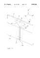
- FIG. 1illustrates a perspective view of one embodiment of the tab monopole of the present invention along with a Cartesian (x-y-z) axis for later reference.
- FIG. 2illustrates a front or plan view of the embodiment of the tab monopole in FIG. 1.
- FIG. 3illustrates a side view of the embodiment of the tab monopole in FIG. 2 further illustrating a backside ground plane.
- FIG. 4illustrates a perspective view of another embodiment of the tab monopole without a supporting dielectric substrate.
- FIG. 5illustrates details of the tab portion of the tab monopole antenna.
- FIG. 6illustrates by way of comparison the measured return loss performance for a prototype tab monopole of the present invention and that of a traditional wire monopole antenna.
- FIGS. 1-3illustrate a preferred embodiment of the tab monopole 2.
- the tab monopole 2is comprised of a sub-wavelength, tapered, radiating element or tab 10, fed by a suitable transmission line 12 and situated above a planar conductive ground plane 14 when the antenna 2 is oriented as illustrated in FIG. 1.
- the tab 10is a thin, flat, planar conductive element having a top edge 16 and a bottom end 18, wherein the top edge 16 is wider than bottom end 18.
- a tapered transition region 20 of the tab 10is located between the top edge 16 and the bottom end 18.
- the tabis connected to the feeding transmission line 12 at the bottom end 18 of the tab 10.
- the tab 10 surfaceis parallel with the ground plane 14 surface.
- the tab 10 and the ground plane 14are constructed from a suitable low loss conductive material or metal, such as but not limited to, copper, gold, silver, brass, or aluminum.
- the tab 10is nominally 0.1 ⁇ high as indicated by H in FIG. 5 measured from the upper edge of ground plane 14 to the top edge 16 of the tab 10.
- the top edge 16 of the tab 10is nominally 0.2 ⁇ wide W. Heights H of between 0.02 ⁇ and 0.5 ⁇ and widths W of between 0.05 ⁇ and 0.9 ⁇ can be used for tab 10.
- the wavelength ⁇herein refers to the free space wavelength.
- the tab 10has a taper angle ⁇ of between twenty and forty degrees (nominally 25 degrees) that begins B wavelengths below the top edge 16 of the tab 10 where B is nominally 0.04 wavelengths and depends on the taper angle ⁇ .
- Tab 10 dimension Bcan range between 0.01 ⁇ and 0.1 ⁇ .
- Exact height, width and taper of the tab 10can be readily chosen by the skilled artisan without undue experimentation to achieve the best match for a given feeding configuration (i.e. impedance and type of feeding transmission line) and ground plane style (e.g. front side and/or back side).
- a given feeding configurationi.e. impedance and type of feeding transmission line
- ground plane stylee.g. front side and/or back side
- the tab monopole 2may be constructed using standard printed circuit board etching processes wherein conventional photo-lithographic methods are used to define a metal pattern on a metalized dielectric substrate.
- Several transmission lines typesare well suited for printed circuit board application including microstrip, stripline, coplanar waveguide and grounded coplanar waveguide.
- a coplanar waveguideis illustrated as the feeding transmission line 12 in FIG. 1.
- a grounded coplanar waveguideis illustrated in FIGS. 2 and 3 as the feeding transmission line 12.
- the tab 10 and the ground plane 14are coplanar.
- the ground plane 14is coplanar with the tab 10 and a second conductive ground plane 15 on the back side of the substrate is used as illustrated in FIG. 3.
- the back side ground plane 15is used without including the ground plane 14 so that the tab 10 and ground plane 15 are not coplanar but are simply parallel.
- the ground plane 15 upper edgeis aligned with the bottom end 18 of the tab 10 as was the case for the ground plane 14.
- the width of the bottom end 18 of tab 10is chosen to be the same as the width of the center conductor 12a of the feeding transmission line 12 to minimize parasitic interactions at the transmission line 12-to-tab 10 boundary.
- the transmission line 12Details of the construction of the transmission line 12 are not provided here since one skilled in the art would be acquainted with these details and since they have no significant impact on the particulars of the tab monopole of the present invention.
- the extent or width of the ground plane 14is likewise of little practical concern and can range from a wavelength to many wavelength. Additionally, a ground plane in the x-y plane, perpendicular to the z-oriented tab 10 can be used instead of the horizontal y-z plane-oriented ground plane depicted in the FIGS. 1-4.
- FIG. 4illustrates a tab monopole 31 having a tab 30 that is unsupported by a dielectric substrate.
- This embodimentcan utilize a coax cable as the feeding transmission line 32.
- the center conductor 32a of the coax transmission line 32can form the bottom end 38 of the tab monopole 31 with a metal sheet forming the tab 30.
- bottom end 38 of tab monopole 31is the point were the center conductor 32a of the coax cable departs from the outer conductor of the coax transmission line 32.
- the ground plane 34can be constructed from a conductive sheet attached to the outer conductor of the coax transmission line 32.
- the tab monopolehas a broad relatively omni directional, radiation pattern in azimuth.
- the azimuth planein this case is the x-y plane for a z-oriented tab as illustrated in FIGS. 1 and 2.
- the tab monopoleis nominally linearly polarized.
- the tab monopoleis found to advantageously and unexpectedly exhibit a wide bandwidth of operation.
- Tab monopole antennas of the present inventionhave operation bandwidths typically greater than 40%. This is in sharp contrast to other sub-wavelength antennas known in the art which typically have bandwidths less than 15%.
- a prototype tab monopole 2was fabricated and tested. The prototype was fabricated using standard double sided printed circuit methods. A 0.0625 inch thick Duroid RT5880 dielectric substrate manufactured by Rogers Corporation of Chandler, Ariz. was used. The substrate material, RT5880, has a dielectric constant of 2.2 and is low loss. The substrate was clad on both sides with 1 ounce copper. The tab 10 and grounded coplanar waveguide transmission line 12 was etched on the front and back side of a 2.75 inch by 5.0 inch substrate. The grounded coplanar waveguide was designed for 50 ohm operation. The tab 10 had a height H of 0.11 ⁇ and a top edge width W of 0.22 ⁇ .
- the tab bottom end 18 widthwas chosen to match that of the coplanar waveguide transmission line 12 center conductor 12a which was 0.1592 inches.
- the design center frequency of the prototypewas 2.6 GHz yielding a tab 10 top edge 16 width W of 1.00 inch and tab height H of 0.57 inches.
- a plurality of viaswere used to provide electrical connection between the ground plane 14 and back ground plane 15 to suppress undesirable propagation modes known to exist in the grounded coplanar waveguide transmission line structure.
- FIG. 6illustrates the measured magnitude return loss, or S 11 magnitude, for the 2.6 GHz prototype tab monopole 2 of FIGS. 2 and 3.
- the measured S 11 magnitude of a conventional wire monopoleis also provided in FIG. 6 for comparison purposes.
- the S 11 measurements presented in FIG. 6were made utilizing an HP 8510B network analyzer with the tab monopole 2 mounted in an anechoic chamber to minimize errors in the measured values.
- the measured input return loss of the tab monopole 2 of the present inventionis less than -10 dB over approximately 1.5 GHz and unexpectedly resulted in an operational bandwidth of greater than 50%.
- the best S11 return losswas better (or less) than -25 dB.
- This wideband operation feature of the inventionovercomes the problem described above for the related art, and consequently, is advantageous for many potential applications of the tab monopole 2.
Landscapes
- Details Of Aerials (AREA)
Abstract
Description
1. Field of the Invention
The present invention relates to wideband, planar antennas. In particular, the present invention is a novel, sub-wavelength, planar monopole antenna that features wideband operation and that can be manufactured using printed circuit methods.
2. Description of the Related Art
The recent, unprecedented growth in the demand for and usage of wireless mobile telephones and the subsequent explosive proliferation of related wireless mobile telecommunication systems has necessarily created a strong interest in compact, sub-wavelength antennas that are easily manufactured and readily integrated into these systems. In parallel with and, in part, resulting from the growth in applications, is a movement from narrow band to wideband systems. A variety of recent advances have begun to focus mobile terminal systems on broadband, spread spectrum and/or multiple frequency, operation leading to the need for much wider bandwidth components for these systems. This, in turn, leads to the need for compact, sub-wavelength mobile terminal antennas which feature wider bandwidth performance than is currently available. Beyond the wireless, mobile terminal application, there is also a need for broad band, readily mass produced, compact antennas for antenna array applications.
The standard, wire monopole is probably the most widely used antenna on existing mobile telecommunication applications with the normal mode helix coming in a close second. The reason for the widespread use of wire monopoles and helices in mobile terminal application is that these antenna are simple and relatively inexpensive to manufacture. Wire monopoles and helices are not, however, particularly easy to integrate into handset or mobile terminal cases. Generally, wire monopoles and helices are manufactured independently of the terminal case, as separate items, that must then be connected to the case and the internal terminal electronics during assembly. The monopoles and helices also protrude from the terminal case subjecting them to damage during use.
Planar antennas, particularly those that can be manufactured using standard printed circuit methods, offer attractive alternatives to the wire monopole and helices for wireless terminal applications. Sub-wavelength, planar antennas known in the art include 1/4 wavelength and 1/2 wavelength patch antennas and the planar inverted F (PIFA) antenna. The 1/2 wavelength patch antenna is approximately 1/2 wavelength in length and width while the 1/4 wavelength patch is 1/4 in length and slightly greater than 1/2 wavelength in width. The PIFA is also sub-wavelength in size usually about 0.2 wavelength in length and 0.1 wavelength wide. All of these patch antennas are readily manufactured using printed circuit methods and feature good, linear polarized radiation patterns suitable for many mobile terminal applications.
In general, sub-wavelength antennas are narrow band. Wire monopoles and helices have operational bandwidths typically on the order of 5-15%. The patch antennas, both 1/4 and 1/2 wavelength, have operational bandwidths typically less than %10 in most cases. PIFA antennas are also narrow band having bandwidths up to approximately 15%.
As used herein, the band width of an antenna is the ratio of the difference between the upper and lower frequency limits of operation to the center frequency. The operational frequencies are those frequencies for which the antenna provides a return loss of below -10 dB.
Therefore, it would be desirable to have a planar antenna that is sub-wavelength in size with significantly wider band operation than existing planar antennas known in the art, and that can be manufactured using standard printed circuit methods. Such an antenna would overcome a long standing problem in the area of antenna technology.
In accordance with the present invention, a new sub-wavelength antenna is provided that by virtue of its unique shape exhibits significantly wider bandwidth operation than existing antennas known in the art. The wideband antenna of the present invention, called a tab monopole, is planar in form enabling it to be readily manufactured using standard printed circuit board methods and facilitating its integration with packages and radio frequency circuitry used to feed the antenna.
The tab monopole antenna of the present invention comprises a thin, planar, conductive tab having a top edge and a bottom end, the top edge being wider than the bottom end, and a tapered region connecting the top edge and bottom end. The tab is located above a ground plane that may or may not be co-planar with the tab. The ground plane has an upper edge that is aligned with the bottom end of the tab. The tab is fed by a suitable transmission line connected to the bottom end of the tab at the ground plane upper edge.
In a preferred embodiment of the present invention, the tab monopole is readily manufactured using standard printed circuit board methods, such that the tab and ground plane can be attached to and supported by a dielectric material.
Alternatively, the tab monopole of the present invention can be fabricated without supporting dielectric using other fabrication techniques.
The tab monopole of the present invention has a tab top edge width of nominally 0.2 wavelengths and a height above the ground plane upper edge of nominally 0.1 wavelengths. The preferred embodiment of the tab monopole of the present invention has a tab tapered region of nominally 25 degrees. The tab monopole antenna of the present invention produces a relatively omni-directional azimuth antenna pattern for vertical polarization. The operational bandwidth in terms of a -10 dB input return loss is unexpectedly and advantageously in excess of 40% with measured values of greater than 50% being typical.
Further details are explained below with the help of the examples illustrated in the attached drawings in which:
FIG. 1 illustrates a perspective view of one embodiment of the tab monopole of the present invention along with a Cartesian (x-y-z) axis for later reference.
FIG. 2 illustrates a front or plan view of the embodiment of the tab monopole in FIG. 1.
FIG. 3 illustrates a side view of the embodiment of the tab monopole in FIG. 2 further illustrating a backside ground plane.
FIG. 4 illustrates a perspective view of another embodiment of the tab monopole without a supporting dielectric substrate.
FIG. 5 illustrates details of the tab portion of the tab monopole antenna.
FIG. 6 illustrates by way of comparison the measured return loss performance for a prototype tab monopole of the present invention and that of a traditional wire monopole antenna.
The tab monopole antenna of the present invention is illustrated in FIG. 1-4. FIGS. 1-3 illustrate a preferred embodiment of thetab monopole 2. Thetab monopole 2 is comprised of a sub-wavelength, tapered, radiating element ortab 10, fed by asuitable transmission line 12 and situated above a planarconductive ground plane 14 when theantenna 2 is oriented as illustrated in FIG. 1. Thetab 10 is a thin, flat, planar conductive element having atop edge 16 and abottom end 18, wherein thetop edge 16 is wider thanbottom end 18. Atapered transition region 20 of thetab 10 is located between thetop edge 16 and thebottom end 18. The tab is connected to thefeeding transmission line 12 at thebottom end 18 of thetab 10. Thetab 10 surface is parallel with theground plane 14 surface. Thetab 10 and theground plane 14 are constructed from a suitable low loss conductive material or metal, such as but not limited to, copper, gold, silver, brass, or aluminum.
Thetab 10 is nominally 0.1 λ high as indicated by H in FIG. 5 measured from the upper edge ofground plane 14 to thetop edge 16 of thetab 10. Thetop edge 16 of thetab 10 is nominally 0.2 λ wide W. Heights H of between 0.02 λ and 0.5λ and widths W of between 0.05λ and 0.9λ can be used fortab 10. The wavelength λ herein refers to the free space wavelength. Thetab 10 has a taper angle Θ of between twenty and forty degrees (nominally 25 degrees) that begins B wavelengths below thetop edge 16 of thetab 10 where B is nominally 0.04 wavelengths and depends on the taper angle Θ.Tab 10 dimension B can range between 0.01λ and 0.1λ. Exact height, width and taper of thetab 10 can be readily chosen by the skilled artisan without undue experimentation to achieve the best match for a given feeding configuration (i.e. impedance and type of feeding transmission line) and ground plane style (e.g. front side and/or back side).
In the preferred embodiment, thetab monopole 2 may be constructed using standard printed circuit board etching processes wherein conventional photo-lithographic methods are used to define a metal pattern on a metalized dielectric substrate. Several transmission lines types are well suited for printed circuit board application including microstrip, stripline, coplanar waveguide and grounded coplanar waveguide. A coplanar waveguide is illustrated as the feedingtransmission line 12 in FIG. 1. A grounded coplanar waveguide is illustrated in FIGS. 2 and 3 as the feedingtransmission line 12. When constructed using printed circuit methods and using a coplanar waveguide, thetab 10 and theground plane 14 are coplanar. In the case of grounded coplanar waveguide, theground plane 14 is coplanar with thetab 10 and a secondconductive ground plane 15 on the back side of the substrate is used as illustrated in FIG. 3. In the case of microstrip, the backside ground plane 15 is used without including theground plane 14 so that thetab 10 andground plane 15 are not coplanar but are simply parallel. When a backside ground plane 15 is used, theground plane 15 upper edge is aligned with thebottom end 18 of thetab 10 as was the case for theground plane 14. In general, the width of thebottom end 18 oftab 10 is chosen to be the same as the width of thecenter conductor 12a of thefeeding transmission line 12 to minimize parasitic interactions at the transmission line 12-to-tab 10 boundary.
Details of the construction of thetransmission line 12 are not provided here since one skilled in the art would be acquainted with these details and since they have no significant impact on the particulars of the tab monopole of the present invention. The extent or width of theground plane 14 is likewise of little practical concern and can range from a wavelength to many wavelength. Additionally, a ground plane in the x-y plane, perpendicular to the z-orientedtab 10 can be used instead of the horizontal y-z plane-oriented ground plane depicted in the FIGS. 1-4.
The tab monopole of the present invention can be manufactured by other than printed circuit methods. FIG. 4 illustrates atab monopole 31 having atab 30 that is unsupported by a dielectric substrate. This embodiment can utilize a coax cable as the feedingtransmission line 32. Thecenter conductor 32a of thecoax transmission line 32 can form thebottom end 38 of thetab monopole 31 with a metal sheet forming thetab 30. In such an embodiment,bottom end 38 oftab monopole 31 is the point were thecenter conductor 32a of the coax cable departs from the outer conductor of thecoax transmission line 32. In addition, as illustrated in FIG. 4, theground plane 34 can be constructed from a conductive sheet attached to the outer conductor of thecoax transmission line 32.
The tab monopole has a broad relatively omni directional, radiation pattern in azimuth. The azimuth plane in this case is the x-y plane for a z-oriented tab as illustrated in FIGS. 1 and 2. The tab monopole is nominally linearly polarized. The tab monopole is found to advantageously and unexpectedly exhibit a wide bandwidth of operation. Tab monopole antennas of the present invention have operation bandwidths typically greater than 40%. This is in sharp contrast to other sub-wavelength antennas known in the art which typically have bandwidths less than 15%.
Aprototype tab monopole 2 was fabricated and tested. The prototype was fabricated using standard double sided printed circuit methods. A 0.0625 inch thick Duroid RT5880 dielectric substrate manufactured by Rogers Corporation of Chandler, Ariz. was used. The substrate material, RT5880, has a dielectric constant of 2.2 and is low loss. The substrate was clad on both sides with 1 ounce copper. Thetab 10 and grounded coplanarwaveguide transmission line 12 was etched on the front and back side of a 2.75 inch by 5.0 inch substrate. The grounded coplanar waveguide was designed for 50 ohm operation. Thetab 10 had a height H of 0.11 λ and a top edge width W of 0.22 λ. The tabbottom end 18 width was chosen to match that of the coplanarwaveguide transmission line 12center conductor 12a which was 0.1592 inches. The design center frequency of the prototype was 2.6 GHz yielding atab 10top edge 16 width W of 1.00 inch and tab height H of 0.57 inches. Thetab 10 taper Θ was 25 degrees and the taper began at B=0.037 wavelengths or 0.17 inches from thetab 10top edge 16. A plurality of vias were used to provide electrical connection between theground plane 14 and background plane 15 to suppress undesirable propagation modes known to exist in the grounded coplanar waveguide transmission line structure.
FIG. 6 illustrates the measured magnitude return loss, or S11 magnitude, for the 2.6 GHzprototype tab monopole 2 of FIGS. 2 and 3. The measured S11 magnitude of a conventional wire monopole is also provided in FIG. 6 for comparison purposes. The S11 measurements presented in FIG. 6 were made utilizing an HP 8510B network analyzer with thetab monopole 2 mounted in an anechoic chamber to minimize errors in the measured values. The measured input return loss of thetab monopole 2 of the present invention is less than -10 dB over approximately 1.5 GHz and unexpectedly resulted in an operational bandwidth of greater than 50%. The best S11 return loss was better (or less) than -25 dB. This wideband operation feature of the invention overcomes the problem described above for the related art, and consequently, is advantageous for many potential applications of thetab monopole 2.
Thus there has been disclosed a new, sub-wavelength, planar antenna called a tab monopole that unexpectedly and advantageously features significantly wider bandwidth operation than planar sub-wavelength antennas known in the art and can be manufactured using standard printed circuit methods. Changes and modifications may be made to the invention which may be readily apparent to those skilled in the art without going beyond the intended scope of the invention, as defined by the appended claims.
Claims (10)
1. A wideband antenna comprising:
a planar conductive tab having a top edge, a tapered region and a bottom end wherein said top edge is wider than said bottom end and said tapered region lies between said top edge and said bottom end;
a planar conductive ground plane that is parallel with said conductive tab and located below said bottom end of said conductive tab, said ground plane having an upper edge that is aligned with said bottom end of said conductive tab; and
a transmission line connected to said bottom end of the planar conductive tab,
wherein said top edge of said conductive tab is nominally 0.2 wavelengths wide and is located nominally 0.1 wavelengths from said upper edge of said ground plane, and
wherein wavelength is a free space wavelength at a center frequency of operation.
2. The wideband antenna as in claim 1, wherein said tapered region has a taper angle of nominally 25 degrees measured from said top edge of said ground plane, and wherein said tapered region begins nominally 0.04 wavelengths below the top edge of the conductive tab.
3. The wideband antenna as in claim 1, wherein said conductive tab, said ground plane and said center conductor of said transmission line are supported by and located on one side of a dielectric substrate.
4. The wideband antenna as in claim 3, wherein said conductive tab, said ground plane and said transmission line are formed on said dielectric substrate by standard printed circuit board fabrication techniques.
5. The wideband antenna of claim 3, further comprising a backside ground plane located on an opposite side of said dielectric substrate, said backside ground plane having an upper edge in alignment with the upper edge of the planar ground plane.
6. The wideband antenna of claim 5, wherein said transmission line is a grounded coplanar waveguide.
7. The wideband antenna of claim 1, wherein said transmission line is a coaxial cable and said bottom end of said conductive tab comprises a center conductor of said coax cable above said upper edge of said ground plane.
8. The wideband antenna of claim 1, wherein said transmission line is a coplanar waveguide.
9. The wideband antenna of claim 1, wherein said conductive tab and said center conductor of said transmission line are supported by and located on one side of a dielectric substrate and said ground plane is located on an opposite side of said dielectric substrate.
10. The wideband antenna of claim 5, wherein said transmission line is a microstrip transmission line.
Priority Applications (1)
| Application Number | Priority Date | Filing Date | Title |
|---|---|---|---|
| US08/736,781US5828340A (en) | 1996-10-25 | 1996-10-25 | Wideband sub-wavelength antenna |
Applications Claiming Priority (1)
| Application Number | Priority Date | Filing Date | Title |
|---|---|---|---|
| US08/736,781US5828340A (en) | 1996-10-25 | 1996-10-25 | Wideband sub-wavelength antenna |
Publications (1)
| Publication Number | Publication Date |
|---|---|
| US5828340Atrue US5828340A (en) | 1998-10-27 |
Family
ID=24961280
Family Applications (1)
| Application Number | Title | Priority Date | Filing Date |
|---|---|---|---|
| US08/736,781Expired - Fee RelatedUS5828340A (en) | 1996-10-25 | 1996-10-25 | Wideband sub-wavelength antenna |
Country Status (1)
| Country | Link |
|---|---|
| US (1) | US5828340A (en) |
Cited By (83)
| Publication number | Priority date | Publication date | Assignee | Title |
|---|---|---|---|---|
| US6008774A (en)* | 1997-03-21 | 1999-12-28 | Celestica International Inc. | Printed antenna structure for wireless data communications |
| US6046703A (en)* | 1998-11-10 | 2000-04-04 | Nutex Communication Corp. | Compact wireless transceiver board with directional printed circuit antenna |
| WO2000046875A1 (en)* | 1999-02-05 | 2000-08-10 | Xertex Technologies, Inc. | Flat panel antenna |
| US6218991B1 (en) | 1999-08-27 | 2001-04-17 | Mohamed Sanad | Compact planar inverted F antenna |
| WO2001037372A1 (en)* | 1999-11-03 | 2001-05-25 | Co-Jot Oy | Plate antenna |
| US6275192B1 (en)* | 2000-05-31 | 2001-08-14 | Samsung Electronics Co., Ltd. | Planar antenna |
| WO2002054536A1 (en)* | 2000-12-29 | 2002-07-11 | Allgon Ab | Antenna with a non-radiating coupling portion |
| JP2003023317A (en)* | 2001-07-11 | 2003-01-24 | Toyo Commun Equip Co Ltd | Printed array antenna |
| US20030076264A1 (en)* | 2001-10-24 | 2003-04-24 | Alps Electric Co., Ltd. | Monopole antenna that can easily be reduced in height dimension |
| US6573866B2 (en)* | 2001-08-29 | 2003-06-03 | Auden Techno Corp. | Multi-frequency hidden antenna for mobile phones |
| EP1324423A1 (en)* | 2001-12-27 | 2003-07-02 | Sony International (Europe) GmbH | Low-cost printed omni-directional monopole antenna for ultra-wideband in mobile applications |
| EP1361624A1 (en)* | 2002-05-10 | 2003-11-12 | Hirschmann Electronics GmbH & Co. KG | Antenna of polygonal shape |
| KR100416883B1 (en)* | 2001-07-27 | 2004-02-05 | (주)신아정보통신 | A wideband monopole antenna |
| EP1337004A3 (en)* | 2002-02-19 | 2004-06-30 | Harada Industry Co., Ltd. | Integrated vehicular antenna system with selectable feedline positioning |
| US20040125020A1 (en)* | 2002-06-04 | 2004-07-01 | Hendler Jason M. | Wideband printed monopole antenna |
| US6784369B2 (en)* | 2001-09-01 | 2004-08-31 | Samsung Electronics Co., Ltd. | Connection structure of coaxial cable |
| US20040178957A1 (en)* | 2003-03-14 | 2004-09-16 | Kuang-Yuan Chang | Multi-band printed monopole antenna |
| US20040196189A1 (en)* | 2003-04-01 | 2004-10-07 | D-Link Corporation | Planar L-shaped antenna of dual frequency |
| US20050001770A1 (en)* | 2003-06-24 | 2005-01-06 | Kyocera Corporation | Antenna, antenna module and radio communication apparatus provided with the same |
| GB2406220A (en)* | 2003-09-22 | 2005-03-23 | Thales Uk Plc | Ultra wide band antenna for pulse transmission and reception |
| US20050062662A1 (en)* | 2003-09-18 | 2005-03-24 | Mitsumi Electric Co. Ltd | Antenna unit having a wide band |
| WO2004077604A3 (en)* | 2003-02-28 | 2005-04-21 | Hk Applied Science & Tech Res | Wideband shorted tapered strip antenna |
| US20050099339A1 (en)* | 2003-11-11 | 2005-05-12 | Mitsumi Electric Co. Ltd. | Gap feeding type antenna unit |
| EP1542315A1 (en)* | 2003-12-08 | 2005-06-15 | Samsung Electronics Co., Ltd. | Ultra-wide band antenna having isotropic radiation pattern |
| US20050156787A1 (en)* | 2004-01-05 | 2005-07-21 | Samsung Electronics Co., Ltd. | Miniaturized ultra-wideband microstrip antenna |
| US20050156783A1 (en)* | 2004-01-20 | 2005-07-21 | Yihua Lu | Dual-band antenna |
| US20050179600A1 (en)* | 2001-06-01 | 2005-08-18 | Agere Systems Inc. | Low-loss printed circuit board antenna structure and method of manufacture thereof |
| US20050233786A1 (en)* | 2004-04-14 | 2005-10-20 | Hatch Robert J | Tapered multiband antenna |
| US20050243009A1 (en)* | 2004-04-29 | 2005-11-03 | Industrial Technology Research Institute | Omnidirectional broadband monopole antenna |
| EP1493204A4 (en)* | 2002-04-05 | 2005-11-16 | Centurion Wireless Tech Inc | Multi-band planar antenna |
| US20050280580A1 (en)* | 2004-06-21 | 2005-12-22 | Ding-Fu Lin | Ultra wide band planar monopole trapezoidal antenna |
| WO2006028212A1 (en)* | 2004-09-10 | 2006-03-16 | Murata Manufacturing Co., Ltd. | Surface implementation type antenna and wireless communication apparatus having the same |
| US20060055612A1 (en)* | 2003-12-31 | 2006-03-16 | Samsung Electronics Co., Ltd. | Ultra-wideband planar antenna having frequency notch function |
| US20060066487A1 (en)* | 2004-09-30 | 2006-03-30 | Jong-Kweon Park | Trapezoid ultra wide band patch antenna |
| US20060071871A1 (en)* | 2004-10-05 | 2006-04-06 | Industrial Technology Research Institute | Omnidirectional ultra-wideband monopole antenna |
| US7042414B1 (en) | 2004-10-26 | 2006-05-09 | Samsung Electro-Mechanics Co., Ltd. | Ultra wideband internal antenna |
| EP1580842A3 (en)* | 2002-10-23 | 2006-05-10 | Sony Corporation | Unbalanced antenna |
| US20060103577A1 (en)* | 2004-11-15 | 2006-05-18 | Samsung Electro-Mechanics Co., Ltd. | Ultra wideband internal antenna |
| US20060176233A1 (en)* | 2005-02-04 | 2006-08-10 | Chia-Lun Tang | Planar monopole antenna |
| US20060208954A1 (en)* | 2005-03-02 | 2006-09-21 | Samsung Electronics Co., Ltd. | Ultra wideband antenna for filtering predetermined frequency band signal and system for receiving ultra wideband signal using the same |
| US20060238420A1 (en)* | 2001-03-01 | 2006-10-26 | Nokia Corporation | Multilayer pcb antenna |
| US20060290571A1 (en)* | 2005-06-22 | 2006-12-28 | Universal Scientific Industrial Co., Ltd. | Ultra wide bandwidth planar antenna |
| US20070069955A1 (en)* | 2005-09-29 | 2007-03-29 | Freescale Semiconductor, Inc. | Frequency-notching antenna |
| US20070103369A1 (en)* | 2005-11-09 | 2007-05-10 | Sony Deutschland Gmbh | Planar antenna apparatus for ultra wide band applications |
| US20070164919A1 (en)* | 2006-01-16 | 2007-07-19 | Samsung Electro-Mechanics Co., Ltd. | Wideband chip antenna |
| US20070194990A1 (en)* | 2005-09-02 | 2007-08-23 | Ching-Wei Ling | Monopole antenna for ultrawideband applications |
| US20070229361A1 (en)* | 2006-03-29 | 2007-10-04 | Fujitsu Component Limited | Antenna apparatus |
| JP2007274099A (en)* | 2006-03-30 | 2007-10-18 | Fujitsu Component Ltd | Antenna unit |
| GB2439110A (en)* | 2006-06-13 | 2007-12-19 | Thales Holdings Uk Plc | Printed ultra-wideband antenna with reduced aperture clutter |
| US20080001826A1 (en)* | 2006-07-03 | 2008-01-03 | Hon Hai Precision Ind. Co., Ltd. | Multi-band antenna |
| US20080012769A1 (en)* | 2006-07-13 | 2008-01-17 | Arcadyan Technology Corporation | Dual band flat antenna |
| US20080024366A1 (en)* | 2006-07-25 | 2008-01-31 | Arcadyan Technology Corporation | Dual band flat antenna |
| CN100369323C (en)* | 2005-03-10 | 2008-02-13 | 上海大学 | Ultra Wideband Trapezoidal Floor Printed Monopole Antenna |
| US20080079635A1 (en)* | 2006-09-28 | 2008-04-03 | Hong Kong Applied Science And Technology Research Institute Co., Ltd. | Antenna systems with ground plane extensions and method for use thereof |
| US20090096677A1 (en)* | 2007-10-11 | 2009-04-16 | Tatung Company | Dual band antenna |
| US20090115667A1 (en)* | 2007-11-07 | 2009-05-07 | Alpha Networks Inc. | Wireless electronic product with step-shaped wideband antenna |
| US20090174608A1 (en)* | 2007-11-29 | 2009-07-09 | Electronics And Telecommunications Research Institute | Non-dispersive uwb antenna apparatus using multi-resonance, and method for manufacturing the same |
| EP2079130A1 (en)* | 2008-01-14 | 2009-07-15 | ASUSTeK Computer Inc. | Antenna module |
| US20090243937A1 (en)* | 2008-03-31 | 2009-10-01 | Tdk Corporation | Two-tier wide band antenna |
| US20090243940A1 (en)* | 2008-03-31 | 2009-10-01 | Tdk Corporation | Feed-point tuned wide band antenna |
| US20090303136A1 (en)* | 2006-02-08 | 2009-12-10 | Akio Kuramoto | Antenna device and communication device using the same |
| ES2337009A1 (en)* | 2009-12-30 | 2010-04-19 | Tecatel, S.A. | "compact antenna with intermediate plate of ceramic material for the reception of digital terrestrial television" (Machine-translation by Google Translate, not legally binding) |
| US20100315303A1 (en)* | 2009-06-10 | 2010-12-16 | Tdk Corporation | Folded slotted monopole antenna |
| JP2011501519A (en)* | 2007-10-08 | 2011-01-06 | センサーマティック・エレクトロニクス・エルエルシー | RFID patch antenna with coplanar reference ground and floating ground |
| US7940218B2 (en) | 2001-03-02 | 2011-05-10 | Nokia Corporation | Multilayer PCB antenna |
| US20110128200A1 (en)* | 2009-11-27 | 2011-06-02 | Fujitsu Limited | Antenna and radio communication apparatus |
| US20110134011A1 (en)* | 2009-12-04 | 2011-06-09 | Fujitsu Limited | Antenna apparatus and wireless communication apparatus |
| US20110298681A1 (en)* | 2010-06-07 | 2011-12-08 | Hon Hai Precision Industry Co., Ltd. | Slot antenna |
| CN102306861A (en)* | 2011-05-19 | 2012-01-04 | 南京邮电大学 | Broadband conversion adapter for coplanar waveguide with shielding backboard and double-sided parallel wire |
| US20120223863A1 (en)* | 2011-03-03 | 2012-09-06 | Nxp B.V. | Multiband Antenna |
| US20130009824A1 (en)* | 2011-07-05 | 2013-01-10 | Arcadyan Technology Corporation | Inverted-f antenna |
| US20130021207A1 (en)* | 2011-07-18 | 2013-01-24 | Lee Youn M | Coplanar-waveguide fed monopole antenna |
| CN101436706B (en)* | 2007-11-13 | 2013-03-27 | 明泰科技股份有限公司 | Wireless Electronics with Ladder-Type Broadband Antennas |
| US20130234895A1 (en)* | 2012-03-06 | 2013-09-12 | Chia-Mei Peng | Multi-band broadband anntenna with mal-position feed structure |
| US20140043197A1 (en)* | 2011-07-18 | 2014-02-13 | U.S. Army Research Labaratory ATTN: RDRL-L-LOC-I | Ultra-wide-band (uwb) antenna assembly with at least one director and electromagnetic reflective subassembly and method |
| WO2015039108A2 (en) | 2013-09-16 | 2015-03-19 | The Board Of Trustees Of The Leland Stanford Junior University | Multi-element coupler for generation of electromagnetic energy |
| WO2016109833A1 (en)* | 2014-12-31 | 2016-07-07 | Chad David Andresen | Patch antenna assembly |
| US20180219295A1 (en)* | 2017-01-30 | 2018-08-02 | Michael Benjamin Griesi | Wideband A-frame Waveguide Probe Antenna |
| US11050167B2 (en)* | 2018-04-19 | 2021-06-29 | Samsung Electronics Co., Ltd. | Antenna array and operation method of antenna array |
| US11338148B2 (en) | 2015-05-15 | 2022-05-24 | NeuSpera Medical Inc. | External power devices and systems |
| US20240097342A1 (en)* | 2021-02-24 | 2024-03-21 | Kyocera Corporation | Antenna, antenna module, and electronic device |
| US12040559B2 (en)* | 2019-06-25 | 2024-07-16 | Viavi Solutions Inc. | Ultra-wideband mobile mount antenna apparatus having a capacitive ground structure-based matching structure |
| US12176725B2 (en) | 2014-05-18 | 2024-12-24 | NeuSpera Medical Inc. | External power devices and systems |
Citations (2)
| Publication number | Priority date | Publication date | Assignee | Title |
|---|---|---|---|---|
| US4063246A (en)* | 1976-06-01 | 1977-12-13 | Transco Products, Inc. | Coplanar stripline antenna |
| US4719470A (en)* | 1985-05-13 | 1988-01-12 | Ball Corporation | Broadband printed circuit antenna with direct feed |
- 1996
- 1996-10-25USUS08/736,781patent/US5828340A/ennot_activeExpired - Fee Related
Patent Citations (2)
| Publication number | Priority date | Publication date | Assignee | Title |
|---|---|---|---|---|
| US4063246A (en)* | 1976-06-01 | 1977-12-13 | Transco Products, Inc. | Coplanar stripline antenna |
| US4719470A (en)* | 1985-05-13 | 1988-01-12 | Ball Corporation | Broadband printed circuit antenna with direct feed |
Cited By (154)
| Publication number | Priority date | Publication date | Assignee | Title |
|---|---|---|---|---|
| US6008774A (en)* | 1997-03-21 | 1999-12-28 | Celestica International Inc. | Printed antenna structure for wireless data communications |
| US6046703A (en)* | 1998-11-10 | 2000-04-04 | Nutex Communication Corp. | Compact wireless transceiver board with directional printed circuit antenna |
| US6249254B1 (en)* | 1999-02-05 | 2001-06-19 | Centurion Wireless Technologies, Inc. | Flat panel antenna |
| WO2000046875A1 (en)* | 1999-02-05 | 2000-08-10 | Xertex Technologies, Inc. | Flat panel antenna |
| US6157344A (en)* | 1999-02-05 | 2000-12-05 | Xertex Technologies, Inc. | Flat panel antenna |
| EP1155471A4 (en)* | 1999-02-05 | 2002-04-17 | Xertex Technologies Inc | Flat panel antenna |
| US6218991B1 (en) | 1999-08-27 | 2001-04-17 | Mohamed Sanad | Compact planar inverted F antenna |
| WO2001037372A1 (en)* | 1999-11-03 | 2001-05-25 | Co-Jot Oy | Plate antenna |
| US6275192B1 (en)* | 2000-05-31 | 2001-08-14 | Samsung Electronics Co., Ltd. | Planar antenna |
| WO2002054536A1 (en)* | 2000-12-29 | 2002-07-11 | Allgon Ab | Antenna with a non-radiating coupling portion |
| US20060238420A1 (en)* | 2001-03-01 | 2006-10-26 | Nokia Corporation | Multilayer pcb antenna |
| US7439919B2 (en) | 2001-03-02 | 2008-10-21 | Nokia Corporation | Multilayer PCB antenna |
| US7940218B2 (en) | 2001-03-02 | 2011-05-10 | Nokia Corporation | Multilayer PCB antenna |
| US7345633B2 (en) | 2001-06-01 | 2008-03-18 | Agere Systems, Inc. | Low-loss substrate antenna structure and method of manufacture thereof |
| US20050179600A1 (en)* | 2001-06-01 | 2005-08-18 | Agere Systems Inc. | Low-loss printed circuit board antenna structure and method of manufacture thereof |
| US20060238421A1 (en)* | 2001-06-01 | 2006-10-26 | Agere Systems Inc. | Low-loss substrate antenna structure and method of manufacture thereof |
| US7113132B2 (en)* | 2001-06-01 | 2006-09-26 | Agere Systems Inc. | Low-loss printed circuit board antenna structure and method of manufacture thereof |
| JP2003023317A (en)* | 2001-07-11 | 2003-01-24 | Toyo Commun Equip Co Ltd | Printed array antenna |
| KR100416883B1 (en)* | 2001-07-27 | 2004-02-05 | (주)신아정보통신 | A wideband monopole antenna |
| US6573866B2 (en)* | 2001-08-29 | 2003-06-03 | Auden Techno Corp. | Multi-frequency hidden antenna for mobile phones |
| US6784369B2 (en)* | 2001-09-01 | 2004-08-31 | Samsung Electronics Co., Ltd. | Connection structure of coaxial cable |
| US6809687B2 (en)* | 2001-10-24 | 2004-10-26 | Alps Electric Co., Ltd. | Monopole antenna that can easily be reduced in height dimension |
| EP1306924A3 (en)* | 2001-10-24 | 2004-10-27 | Alps Electric Co., Ltd. | Monopole antenna that can easily be reduced in height dimension |
| US20030076264A1 (en)* | 2001-10-24 | 2003-04-24 | Alps Electric Co., Ltd. | Monopole antenna that can easily be reduced in height dimension |
| EP1324423A1 (en)* | 2001-12-27 | 2003-07-02 | Sony International (Europe) GmbH | Low-cost printed omni-directional monopole antenna for ultra-wideband in mobile applications |
| EP1337004A3 (en)* | 2002-02-19 | 2004-06-30 | Harada Industry Co., Ltd. | Integrated vehicular antenna system with selectable feedline positioning |
| CN100466377C (en)* | 2002-04-05 | 2009-03-04 | 圣韵无线技术公司 | Multiband Planar Antenna |
| EP1493204A4 (en)* | 2002-04-05 | 2005-11-16 | Centurion Wireless Tech Inc | Multi-band planar antenna |
| EP1361624A1 (en)* | 2002-05-10 | 2003-11-12 | Hirschmann Electronics GmbH & Co. KG | Antenna of polygonal shape |
| US20040125020A1 (en)* | 2002-06-04 | 2004-07-01 | Hendler Jason M. | Wideband printed monopole antenna |
| US6937193B2 (en) | 2002-06-04 | 2005-08-30 | Skycross, Inc. | Wideband printed monopole antenna |
| US7180466B2 (en) | 2002-10-23 | 2007-02-20 | Sony Corporation | Unbalanced antenna |
| US20070176828A1 (en)* | 2002-10-23 | 2007-08-02 | Sony Corporation | Unbalanced antenna |
| EP1580842A3 (en)* | 2002-10-23 | 2006-05-10 | Sony Corporation | Unbalanced antenna |
| US7515114B2 (en) | 2002-10-23 | 2009-04-07 | Sony Corporation | Unbalanced antenna |
| US20060214869A1 (en)* | 2002-10-23 | 2006-09-28 | Sony Corporation | Unbalanced antenna |
| WO2004077604A3 (en)* | 2003-02-28 | 2005-04-21 | Hk Applied Science & Tech Res | Wideband shorted tapered strip antenna |
| US20040178957A1 (en)* | 2003-03-14 | 2004-09-16 | Kuang-Yuan Chang | Multi-band printed monopole antenna |
| US6801169B1 (en)* | 2003-03-14 | 2004-10-05 | Hon Hai Precision Ind. Co., Ltd. | Multi-band printed monopole antenna |
| US6850192B2 (en)* | 2003-04-01 | 2005-02-01 | D-Link Corporation | Planar L-shaped antenna of dual frequency |
| US20040196189A1 (en)* | 2003-04-01 | 2004-10-07 | D-Link Corporation | Planar L-shaped antenna of dual frequency |
| US20050001770A1 (en)* | 2003-06-24 | 2005-01-06 | Kyocera Corporation | Antenna, antenna module and radio communication apparatus provided with the same |
| US7098852B2 (en) | 2003-06-24 | 2006-08-29 | Kyocera Corporation | Antenna, antenna module and radio communication apparatus provided with the same |
| JP2005094437A (en)* | 2003-09-18 | 2005-04-07 | Mitsumi Electric Co Ltd | Antenna for uwb |
| US7081859B2 (en)* | 2003-09-18 | 2006-07-25 | Mitsumi Electric Co., Ltd. | Antenna unit having a wide band |
| US20050062662A1 (en)* | 2003-09-18 | 2005-03-24 | Mitsumi Electric Co. Ltd | Antenna unit having a wide band |
| GB2406220B (en)* | 2003-09-22 | 2006-10-18 | Thales Uk Plc | An antenna |
| GB2406220A (en)* | 2003-09-22 | 2005-03-23 | Thales Uk Plc | Ultra wide band antenna for pulse transmission and reception |
| US7239283B2 (en) | 2003-09-22 | 2007-07-03 | Thales Plc | Antenna |
| US20050078042A1 (en)* | 2003-09-22 | 2005-04-14 | Thales Plc | Antenna |
| JP2005150804A (en)* | 2003-11-11 | 2005-06-09 | Mitsumi Electric Co Ltd | Antenna apparatus |
| US7019698B2 (en) | 2003-11-11 | 2006-03-28 | Mitsumi Electric Co., Ltd. | Gap feeding type antenna unit |
| EP1531516A1 (en)* | 2003-11-11 | 2005-05-18 | Mitsumi Electric Co., Ltd. | Capacitively fed ultra wide band monopole antenna |
| US20050099339A1 (en)* | 2003-11-11 | 2005-05-12 | Mitsumi Electric Co. Ltd. | Gap feeding type antenna unit |
| US20050146471A1 (en)* | 2003-12-08 | 2005-07-07 | Samsung Electronics Co., Ltd. | Ultra-wideband antenna having an isotropic radiation pattern |
| KR100846487B1 (en)* | 2003-12-08 | 2008-07-17 | 삼성전자주식회사 | Ultra-wideband antenna with isotropic radiation pattern |
| EP1542315A1 (en)* | 2003-12-08 | 2005-06-15 | Samsung Electronics Co., Ltd. | Ultra-wide band antenna having isotropic radiation pattern |
| US7050013B2 (en) | 2003-12-31 | 2006-05-23 | Samsung Electronics Co., Ltd. | Ultra-wideband planar antenna having frequency notch function |
| US20060055612A1 (en)* | 2003-12-31 | 2006-03-16 | Samsung Electronics Co., Ltd. | Ultra-wideband planar antenna having frequency notch function |
| US7324049B2 (en)* | 2004-01-05 | 2008-01-29 | Samsung Electronics Co., Ltd. | Miniaturized ultra-wideband microstrip antenna |
| US20050156787A1 (en)* | 2004-01-05 | 2005-07-21 | Samsung Electronics Co., Ltd. | Miniaturized ultra-wideband microstrip antenna |
| US6992631B2 (en)* | 2004-01-20 | 2006-01-31 | Micro-Star Int'l Co., Ltd. | Dual-band antenna |
| US20050156783A1 (en)* | 2004-01-20 | 2005-07-21 | Yihua Lu | Dual-band antenna |
| US7202819B2 (en)* | 2004-04-14 | 2007-04-10 | Qualcomm Incorporated | Tapered multiband antenna |
| US20050233786A1 (en)* | 2004-04-14 | 2005-10-20 | Hatch Robert J | Tapered multiband antenna |
| US20050243009A1 (en)* | 2004-04-29 | 2005-11-03 | Industrial Technology Research Institute | Omnidirectional broadband monopole antenna |
| US7327327B2 (en) | 2004-04-29 | 2008-02-05 | Industrial Technology Research Institute | Omnidirectional broadband monopole antenna |
| US20050280580A1 (en)* | 2004-06-21 | 2005-12-22 | Ding-Fu Lin | Ultra wide band planar monopole trapezoidal antenna |
| WO2006028212A1 (en)* | 2004-09-10 | 2006-03-16 | Murata Manufacturing Co., Ltd. | Surface implementation type antenna and wireless communication apparatus having the same |
| US20080018538A1 (en)* | 2004-09-10 | 2008-01-24 | Murata Manufacturing Co., Ltd. | Surface-Mount Antenna and Radio Communication Apparatus Including the Same |
| US20060066487A1 (en)* | 2004-09-30 | 2006-03-30 | Jong-Kweon Park | Trapezoid ultra wide band patch antenna |
| US7042401B2 (en) | 2004-09-30 | 2006-05-09 | Electronics And Telecommunications Research Institute | Trapezoid ultra wide band patch antenna |
| US7495616B2 (en) | 2004-10-05 | 2009-02-24 | Industrial Technology Research Institute | Omnidirectional ultra-wideband monopole antenna |
| US20060071871A1 (en)* | 2004-10-05 | 2006-04-06 | Industrial Technology Research Institute | Omnidirectional ultra-wideband monopole antenna |
| US20060097925A1 (en)* | 2004-10-26 | 2006-05-11 | Samsung Electro-Mechanics Co., Ltd. | Ultra wideband internal antenna |
| US7042414B1 (en) | 2004-10-26 | 2006-05-09 | Samsung Electro-Mechanics Co., Ltd. | Ultra wideband internal antenna |
| US20060103577A1 (en)* | 2004-11-15 | 2006-05-18 | Samsung Electro-Mechanics Co., Ltd. | Ultra wideband internal antenna |
| US7116276B2 (en) | 2004-11-15 | 2006-10-03 | Samsung Electro-Mechanics Co., Ltd. | Ultra wideband internal antenna |
| US7126543B2 (en) | 2005-02-04 | 2006-10-24 | Industrial Technology Research Institute | Planar monopole antenna |
| US20060176233A1 (en)* | 2005-02-04 | 2006-08-10 | Chia-Lun Tang | Planar monopole antenna |
| US7557755B2 (en)* | 2005-03-02 | 2009-07-07 | Samsung Electronics Co., Ltd. | Ultra wideband antenna for filtering predetermined frequency band signal and system for receiving ultra wideband signal using the same |
| US20060208954A1 (en)* | 2005-03-02 | 2006-09-21 | Samsung Electronics Co., Ltd. | Ultra wideband antenna for filtering predetermined frequency band signal and system for receiving ultra wideband signal using the same |
| CN100369323C (en)* | 2005-03-10 | 2008-02-13 | 上海大学 | Ultra Wideband Trapezoidal Floor Printed Monopole Antenna |
| US20060290571A1 (en)* | 2005-06-22 | 2006-12-28 | Universal Scientific Industrial Co., Ltd. | Ultra wide bandwidth planar antenna |
| US20070194990A1 (en)* | 2005-09-02 | 2007-08-23 | Ching-Wei Ling | Monopole antenna for ultrawideband applications |
| US20070069955A1 (en)* | 2005-09-29 | 2007-03-29 | Freescale Semiconductor, Inc. | Frequency-notching antenna |
| US7352333B2 (en)* | 2005-09-29 | 2008-04-01 | Freescale Semiconductor, Inc. | Frequency-notching antenna |
| US7545339B2 (en) | 2005-11-09 | 2009-06-09 | Sony Deutschland Gmbh | Planar antenna apparatus for ultra wide band applications |
| US20070103369A1 (en)* | 2005-11-09 | 2007-05-10 | Sony Deutschland Gmbh | Planar antenna apparatus for ultra wide band applications |
| EP1786064A1 (en)* | 2005-11-09 | 2007-05-16 | Sony Deutschland GmbH | Planar antenna apparatus for ultra wide band applications |
| US20070164919A1 (en)* | 2006-01-16 | 2007-07-19 | Samsung Electro-Mechanics Co., Ltd. | Wideband chip antenna |
| TWI413302B (en)* | 2006-02-08 | 2013-10-21 | Nec Corp | Monopole antenna device and communication device using the same |
| US20090303136A1 (en)* | 2006-02-08 | 2009-12-10 | Akio Kuramoto | Antenna device and communication device using the same |
| US20070229361A1 (en)* | 2006-03-29 | 2007-10-04 | Fujitsu Component Limited | Antenna apparatus |
| JP2007274099A (en)* | 2006-03-30 | 2007-10-18 | Fujitsu Component Ltd | Antenna unit |
| GB2439110B (en)* | 2006-06-13 | 2009-08-19 | Thales Holdings Uk Plc | An ultra wideband antenna |
| GB2439110A (en)* | 2006-06-13 | 2007-12-19 | Thales Holdings Uk Plc | Printed ultra-wideband antenna with reduced aperture clutter |
| US7737901B2 (en) | 2006-07-03 | 2010-06-15 | Hon Hai Precision Ind. Co., Ltd | Multi-band antenna |
| US20080001826A1 (en)* | 2006-07-03 | 2008-01-03 | Hon Hai Precision Ind. Co., Ltd. | Multi-band antenna |
| US20080012769A1 (en)* | 2006-07-13 | 2008-01-17 | Arcadyan Technology Corporation | Dual band flat antenna |
| US20080024366A1 (en)* | 2006-07-25 | 2008-01-31 | Arcadyan Technology Corporation | Dual band flat antenna |
| US7535431B2 (en)* | 2006-09-28 | 2009-05-19 | Hong Kong Applied Science And Technology Research Institute Co., Ltd. | Antenna systems with ground plane extensions and method for use thereof |
| US20080079635A1 (en)* | 2006-09-28 | 2008-04-03 | Hong Kong Applied Science And Technology Research Institute Co., Ltd. | Antenna systems with ground plane extensions and method for use thereof |
| JP2011501519A (en)* | 2007-10-08 | 2011-01-06 | センサーマティック・エレクトロニクス・エルエルシー | RFID patch antenna with coplanar reference ground and floating ground |
| US20090096677A1 (en)* | 2007-10-11 | 2009-04-16 | Tatung Company | Dual band antenna |
| US7639186B2 (en)* | 2007-10-11 | 2009-12-29 | Tatung Company | Dual band antenna |
| US20090115667A1 (en)* | 2007-11-07 | 2009-05-07 | Alpha Networks Inc. | Wireless electronic product with step-shaped wideband antenna |
| US7589677B2 (en)* | 2007-11-07 | 2009-09-15 | Alpha Networks, Inc. | Wireless electronic product with step-shaped wideband antenna |
| CN101436706B (en)* | 2007-11-13 | 2013-03-27 | 明泰科技股份有限公司 | Wireless Electronics with Ladder-Type Broadband Antennas |
| US20090174608A1 (en)* | 2007-11-29 | 2009-07-09 | Electronics And Telecommunications Research Institute | Non-dispersive uwb antenna apparatus using multi-resonance, and method for manufacturing the same |
| US20090179804A1 (en)* | 2008-01-14 | 2009-07-16 | Asustek Computer Inc. | Antenna module |
| EP2079130A1 (en)* | 2008-01-14 | 2009-07-15 | ASUSTeK Computer Inc. | Antenna module |
| EP2107635A1 (en) | 2008-03-31 | 2009-10-07 | TDK Corporation | Two-tier wide band antenna |
| US7742001B2 (en) | 2008-03-31 | 2010-06-22 | Tdk Corporation | Two-tier wide band antenna |
| US7800543B2 (en) | 2008-03-31 | 2010-09-21 | Tdk Corporation | Feed-point tuned wide band antenna |
| US20090243940A1 (en)* | 2008-03-31 | 2009-10-01 | Tdk Corporation | Feed-point tuned wide band antenna |
| US20090243937A1 (en)* | 2008-03-31 | 2009-10-01 | Tdk Corporation | Two-tier wide band antenna |
| US20100315303A1 (en)* | 2009-06-10 | 2010-12-16 | Tdk Corporation | Folded slotted monopole antenna |
| US8081122B2 (en) | 2009-06-10 | 2011-12-20 | Tdk Corporation | Folded slotted monopole antenna |
| US8552916B2 (en)* | 2009-11-27 | 2013-10-08 | Fujitsu Limited | Antenna and radio communication apparatus |
| US20110128200A1 (en)* | 2009-11-27 | 2011-06-02 | Fujitsu Limited | Antenna and radio communication apparatus |
| US20110134011A1 (en)* | 2009-12-04 | 2011-06-09 | Fujitsu Limited | Antenna apparatus and wireless communication apparatus |
| ES2337009B2 (en)* | 2009-12-30 | 2011-02-07 | Tecatel, S.A. | "COMPACT ANTENNA WITH INTERMEDIATE CERAMIC PLATE FOR RECEPTION OF DIGITAL TERRESTRIAL TELEVISION". |
| ES2337009A1 (en)* | 2009-12-30 | 2010-04-19 | Tecatel, S.A. | "compact antenna with intermediate plate of ceramic material for the reception of digital terrestrial television" (Machine-translation by Google Translate, not legally binding) |
| US8274442B2 (en)* | 2010-06-07 | 2012-09-25 | Hon Hai Precision Industry Co., Ltd. | Slot antenna |
| US20110298681A1 (en)* | 2010-06-07 | 2011-12-08 | Hon Hai Precision Industry Co., Ltd. | Slot antenna |
| US20120223863A1 (en)* | 2011-03-03 | 2012-09-06 | Nxp B.V. | Multiband Antenna |
| US9379430B2 (en)* | 2011-03-03 | 2016-06-28 | Nxp B.V. | Multiband antenna |
| CN102306861A (en)* | 2011-05-19 | 2012-01-04 | 南京邮电大学 | Broadband conversion adapter for coplanar waveguide with shielding backboard and double-sided parallel wire |
| US20130009824A1 (en)* | 2011-07-05 | 2013-01-10 | Arcadyan Technology Corporation | Inverted-f antenna |
| US9130261B2 (en)* | 2011-07-05 | 2015-09-08 | Arcadyan Technology Corporation | Inverted-F antenna |
| US20140043197A1 (en)* | 2011-07-18 | 2014-02-13 | U.S. Army Research Labaratory ATTN: RDRL-L-LOC-I | Ultra-wide-band (uwb) antenna assembly with at least one director and electromagnetic reflective subassembly and method |
| US9444147B2 (en)* | 2011-07-18 | 2016-09-13 | The United States Of America As Represented By The Secretary Of The Army | Ultra-wide-band (UWB) antenna assembly with at least one director and electromagnetic reflective subassembly and method |
| US20130021207A1 (en)* | 2011-07-18 | 2013-01-24 | Lee Youn M | Coplanar-waveguide fed monopole antenna |
| US8836599B2 (en)* | 2012-03-06 | 2014-09-16 | I-Fong Chen | Multi-band broadband antenna with mal-position feed structure |
| US20130234895A1 (en)* | 2012-03-06 | 2013-09-12 | Chia-Mei Peng | Multi-band broadband anntenna with mal-position feed structure |
| EP3046621A4 (en)* | 2013-09-16 | 2017-03-29 | The Board of Trustees of The Leland Stanford Junior University | Multi-element coupler for generation of electromagnetic energy |
| AU2014318413B2 (en)* | 2013-09-16 | 2019-07-11 | The Board Of Trustees Of The Leland Stanford Junior University | Multi-element coupler for generation of electromagnetic energy |
| WO2015039108A2 (en) | 2013-09-16 | 2015-03-19 | The Board Of Trustees Of The Leland Stanford Junior University | Multi-element coupler for generation of electromagnetic energy |
| US9662507B2 (en) | 2013-09-16 | 2017-05-30 | The Board Of Trustees Of The Leland Stanford Junior University | Multi-element coupler for generation of electromagnetic energy |
| US9687664B2 (en) | 2013-09-16 | 2017-06-27 | The Board Of Trustees Of The Leland Stanford Junior University | Multi-element coupler for generation of electromagnetic energy |
| US9744369B2 (en) | 2013-09-16 | 2017-08-29 | The Board Of Trustees Of The Leland Stanford Junior University | Multi-element coupler for generation of electromagnetic energy |
| EP3903876A1 (en)* | 2013-09-16 | 2021-11-03 | The Board of Trustees of the Leland Stanford Junior University | Multi-element coupler for generation of electromagnetic energy |
| US10039924B2 (en) | 2013-09-16 | 2018-08-07 | The Board Of Trustees Of The Leland Stanford Junior University | Wireless midfield systems and methods |
| AU2019246841B2 (en)* | 2013-09-16 | 2019-11-28 | The Board Of Trustees Of The Leland Stanford Junior University | Multi-element coupler for generation of electromagnetic energy |
| US12176725B2 (en) | 2014-05-18 | 2024-12-24 | NeuSpera Medical Inc. | External power devices and systems |
| WO2016109833A1 (en)* | 2014-12-31 | 2016-07-07 | Chad David Andresen | Patch antenna assembly |
| US10056688B2 (en) | 2014-12-31 | 2018-08-21 | Micron Devices Llc | Patch antenna assembly |
| US11128049B2 (en) | 2014-12-31 | 2021-09-21 | Stimwave Technologies Incorporated | Patch antenna assembly |
| US11338148B2 (en) | 2015-05-15 | 2022-05-24 | NeuSpera Medical Inc. | External power devices and systems |
| US20180219295A1 (en)* | 2017-01-30 | 2018-08-02 | Michael Benjamin Griesi | Wideband A-frame Waveguide Probe Antenna |
| US11050167B2 (en)* | 2018-04-19 | 2021-06-29 | Samsung Electronics Co., Ltd. | Antenna array and operation method of antenna array |
| US12040559B2 (en)* | 2019-06-25 | 2024-07-16 | Viavi Solutions Inc. | Ultra-wideband mobile mount antenna apparatus having a capacitive ground structure-based matching structure |
| US20240097342A1 (en)* | 2021-02-24 | 2024-03-21 | Kyocera Corporation | Antenna, antenna module, and electronic device |
Similar Documents
| Publication | Publication Date | Title |
|---|---|---|
| US5828340A (en) | Wideband sub-wavelength antenna | |
| US6043785A (en) | Broadband fixed-radius slot antenna arrangement | |
| US6842158B2 (en) | Wideband low profile spiral-shaped transmission line antenna | |
| US7333067B2 (en) | Multi-band antenna with wide bandwidth | |
| US6429819B1 (en) | Dual band patch bowtie slot antenna structure | |
| US6509882B2 (en) | Low SAR broadband antenna assembly | |
| US6137445A (en) | Antenna apparatus for mobile terminal | |
| US6281843B1 (en) | Planar broadband dipole antenna for linearly polarized waves | |
| US5400041A (en) | Radiating element incorporating impedance transformation capabilities | |
| US6515629B1 (en) | Dual-band inverted-F antenna | |
| EP0637094B1 (en) | Antenna for mobile communication | |
| US6404394B1 (en) | Dual polarization slot antenna assembly | |
| US6606067B2 (en) | Apparatus for wideband directional antenna | |
| US20030063031A1 (en) | Broadband circularly polarized patch antenna | |
| JP2004201281A (en) | Wireless lan antenna and wireless lan card provided with the same | |
| US20010045908A1 (en) | Dual frequency wideband radiator | |
| US7230573B2 (en) | Dual-band antenna with an impedance transformer | |
| US6091366A (en) | Microstrip type antenna device | |
| US6646619B2 (en) | Broadband antenna assembly of matching circuitry and ground plane conductive radiating element | |
| US6977613B2 (en) | High performance dual-patch antenna with fast impedance matching holes | |
| US20050237244A1 (en) | Compact RF antenna | |
| US20020163471A1 (en) | Multiple band antenna having isolated feeds | |
| WO1991005374A1 (en) | Monopole antenna | |
| US7855686B2 (en) | Compact antennas for ultra-wideband applications | |
| KR20090016358A (en) | Circuit Board Integrated Antenna |
Legal Events
| Date | Code | Title | Description |
|---|---|---|---|
| REMI | Maintenance fee reminder mailed | ||
| LAPS | Lapse for failure to pay maintenance fees | ||
| STCH | Information on status: patent discontinuation | Free format text:PATENT EXPIRED DUE TO NONPAYMENT OF MAINTENANCE FEES UNDER 37 CFR 1.362 | |
| FP | Lapsed due to failure to pay maintenance fee | Effective date:20021027 |