US5828293A - Data transmission over a power line communications system - Google Patents
Data transmission over a power line communications systemDownload PDFInfo
- Publication number
- US5828293A US5828293AUS08/871,930US87193097AUS5828293AUS 5828293 AUS5828293 AUS 5828293AUS 87193097 AUS87193097 AUS 87193097AUS 5828293 AUS5828293 AUS 5828293A
- Authority
- US
- United States
- Prior art keywords
- line
- phase
- quiet
- power line
- noise
- Prior art date
- Legal status (The legal status is an assumption and is not a legal conclusion. Google has not performed a legal analysis and makes no representation as to the accuracy of the status listed.)
- Expired - Lifetime
Links
- 238000004891communicationMethods0.000titleclaimsabstractdescription20
- 230000005540biological transmissionEffects0.000titledescription27
- 238000000034methodMethods0.000claimsdescription38
- 238000011144upstream manufacturingMethods0.000claimsdescription13
- 238000012544monitoring processMethods0.000claimsdescription12
- 230000000737periodic effectEffects0.000claimsdescription10
- 238000012360testing methodMethods0.000claimsdescription8
- 125000004122cyclic groupChemical group0.000claimsdescription2
- 230000005611electricityEffects0.000description7
- 230000008901benefitEffects0.000description4
- 230000008878couplingEffects0.000description4
- 238000010168coupling processMethods0.000description4
- 238000005859coupling reactionMethods0.000description4
- 230000000694effectsEffects0.000description3
- 238000005259measurementMethods0.000description3
- 230000007935neutral effectEffects0.000description3
- 230000000903blocking effectEffects0.000description2
- 238000012937correctionMethods0.000description2
- 230000001419dependent effectEffects0.000description2
- 238000001514detection methodMethods0.000description2
- 238000009434installationMethods0.000description2
- 238000010079rubber tappingMethods0.000description2
- 238000012546transferMethods0.000description2
- 230000032258transportEffects0.000description2
- 238000004458analytical methodMethods0.000description1
- 238000004883computer applicationMethods0.000description1
- 230000007423decreaseEffects0.000description1
- 238000010586diagramMethods0.000description1
- 238000007689inspectionMethods0.000description1
- 230000002045lasting effectEffects0.000description1
- 238000012986modificationMethods0.000description1
- 230000004048modificationEffects0.000description1
- 238000012545processingMethods0.000description1
- 230000009467reductionEffects0.000description1
- 230000004044responseEffects0.000description1
- 238000005070samplingMethods0.000description1
- 230000011664signalingEffects0.000description1
Images


Classifications
- H—ELECTRICITY
- H04—ELECTRIC COMMUNICATION TECHNIQUE
- H04B—TRANSMISSION
- H04B3/00—Line transmission systems
- H04B3/54—Systems for transmission via power distribution lines
- H04B3/542—Systems for transmission via power distribution lines the information being in digital form
- H—ELECTRICITY
- H04—ELECTRIC COMMUNICATION TECHNIQUE
- H04B—TRANSMISSION
- H04B2203/00—Indexing scheme relating to line transmission systems
- H04B2203/54—Aspects of powerline communications not already covered by H04B3/54 and its subgroups
- H04B2203/5404—Methods of transmitting or receiving signals via power distribution lines
- H04B2203/542—Methods of transmitting or receiving signals via power distribution lines using zero crossing information
- H—ELECTRICITY
- H04—ELECTRIC COMMUNICATION TECHNIQUE
- H04B—TRANSMISSION
- H04B2203/00—Indexing scheme relating to line transmission systems
- H04B2203/54—Aspects of powerline communications not already covered by H04B3/54 and its subgroups
- H04B2203/5404—Methods of transmitting or receiving signals via power distribution lines
- H04B2203/5425—Methods of transmitting or receiving signals via power distribution lines improving S/N by matching impedance, noise reduction, gain control
- H—ELECTRICITY
- H04—ELECTRIC COMMUNICATION TECHNIQUE
- H04B—TRANSMISSION
- H04B2203/00—Indexing scheme relating to line transmission systems
- H04B2203/54—Aspects of powerline communications not already covered by H04B3/54 and its subgroups
- H04B2203/5429—Applications for powerline communications
- H04B2203/5445—Local network
- H—ELECTRICITY
- H04—ELECTRIC COMMUNICATION TECHNIQUE
- H04B—TRANSMISSION
- H04B2203/00—Indexing scheme relating to line transmission systems
- H04B2203/54—Aspects of powerline communications not already covered by H04B3/54 and its subgroups
- H04B2203/5429—Applications for powerline communications
- H04B2203/5458—Monitor sensor; Alarm systems
- H—ELECTRICITY
- H04—ELECTRIC COMMUNICATION TECHNIQUE
- H04B—TRANSMISSION
- H04B2203/00—Indexing scheme relating to line transmission systems
- H04B2203/54—Aspects of powerline communications not already covered by H04B3/54 and its subgroups
- H04B2203/5462—Systems for power line communications
- H04B2203/5466—Systems for power line communications using three phases conductors
- H—ELECTRICITY
- H04—ELECTRIC COMMUNICATION TECHNIQUE
- H04B—TRANSMISSION
- H04B2203/00—Indexing scheme relating to line transmission systems
- H04B2203/54—Aspects of powerline communications not already covered by H04B3/54 and its subgroups
- H04B2203/5462—Systems for power line communications
- H04B2203/5483—Systems for power line communications using coupling circuits
- H—ELECTRICITY
- H04—ELECTRIC COMMUNICATION TECHNIQUE
- H04B—TRANSMISSION
- H04B2203/00—Indexing scheme relating to line transmission systems
- H04B2203/54—Aspects of powerline communications not already covered by H04B3/54 and its subgroups
- H04B2203/5462—Systems for power line communications
- H04B2203/5495—Systems for power line communications having measurements and testing channel
Definitions
- This inventionrelates to transmission of data over a power line.
- a first methoduses the power signal itself, modifying the shape of the power signal at certain known points in response to the data which is to be carried. An example of this is shown in UK Patent GB 1,600,056.
- a second methoduses a carrier signal having a different frequency from that of the power signal, the carrier signal being modulated by the data.
- Power linesare subject to significant levels of noise and interference.
- a first type of noiseis due to cables picking up radio signals such as broadcast AM radio signals and amateur radio band transmissions. Overhead cables are particularly prone to this type of noise.
- a second type of electrical noiseis due to electrical equipment coupled to the power lines. Electric motors, thermostats and gas discharge lighting are particularly prone to generating noise. Noise propagates along the power lines and combines with communications signals. The level of noise is frequently high enough, and persists for long enough, to corrupt communications signals.
- Noiseimposes several constraints when using the power line to carry data. Firstly, data which is corrupted by the noise requires re-transmission. Secondly, each transmission must include a high error detection and correction overhead to ensure that corrupted data is detected and, if possible, corrected at the receiving unit. Both of these factors reduce throughput over the transmission medium, which results in a subscriber experiencing longer transmission times and a higher probability of blocking when they attempt to access the communications medium.
- a known protocol called ⁇ X-10 ⁇transmits short bursts of a 120 kHz tone at regular points in an AC power signal.
- the X-10 protocolis intended for in-house signalling to control lighting and electrical equipment and has a slow rate of data transfer.
- a binary ⁇ 1 ⁇is represented by a short burst of 120 kHz tone and a binary ⁇ 0 ⁇ is represented by absence of the 120 kHz tone, the tones being transmitted shortly after the zero-crossing points of the power line signal.
- a single bit of datais transmitted after each zero-crossing point.
- JP-07-226778describes a transmission system in which data is continuously transmitted over an electrical power distribution line at a low data rate and sampling of the data signal is performed near a zero-crossing point of the power supply voltage.
- the present inventionseeks to provide an improved data transmission scheme.
- a method of transmitting data over a power line upon which noise level varies with timecomprising:
- Transmitting during a quiet periodhas the advantages of reducing the amount of data requiring retransmission and allowing a lower error detection and correction overhead in each packet which improves throughput of data over the power line and reduces blocking of other users. Transmitting a self-contained data packet during a quiet period rather than a single bit of data that is part of a longer message also provides increased data throughput and allows better use to be made of the quiet periods occurring on the line. Each quiet period that occurs on the line can be used to transmit data to a particular subscriber independently of the use made of other quiet periods.
- the methodis particularly efficient at increasing throughput where the power line comprises a plurality of phase lines, and the step of transmitting comprises transmitting a data packet to a subscriber station on a particular phase line only during a quiet period occurring on that phase line. It has been found that quiet periods tend to occur independently of one another such that one phase line will experience a quiet period while the other phase lines are experiencing a high level of noise.
- the methodcomprises sequentially transmitting to subscribers that are coupled to different phase lines, one at a time, in a cyclic fashion. Transmitting to a particular subscriber only during a quiet period on their line, rather than repeating a transmission several times to coincide with quiet periods on each line, further increases data throughput.
- the step of transmittingcan comprise transmitting over a particular phase line within the quietest duration T/n on that line.
- This quietest duration T/nmay be divided among two or more quiet windows depending on the frequency of the noise envelope.
- the power linecarries a periodic power signal, the quiet periods being located about a characteristic point of the power signal, and wherein the step of determining a quiet period comprises determining the quiet period based on the timing of the characteristic point.
- the power signalis an alternating power signal which has a plurality of zero-crossing points, the quiet periods extending each side of the zero-crossing points, and the step of transmitting comprises transmitting the data packet such that it extends in time each side of the zero-crossing point. This has the advantage of making best use of the quiet period.
- the data packetcan be transmitted such that it extends unequally each side of the zero-crossing point, such as where a particular part of the packet contains important data, such as a token.
- the step of determining quiet periodscomprises predicting future quiet periods based on the periodic nature of the power signal.
- Noise level on the linecan also be monitored and the quiet period can be determined based on the timing of the characteristic point and the monitored noise.
- a base stationcan determine the phase line to which a subscriber station is coupled by:
- the quiet periodscan be determined by monitoring a first phase line and determining quiet periods on other phase according to the monitoring of the first phase line and the predetermined phase relationship. This avoids the need for one monitor for each phase line.
- the packetcan be transmitted such that the token is transmitted during the quietest portion of the determined quiet period.
- a downstream packetcan be transmitted from a first station to a second station and an upstream packet can be transmitted from the second station to the first station during the determined quiet period. This allows the majority of the equipment required for the method to be located at the first station.
- a quiet periodcan be determined by monitoring noise level on the power line.
- the methodcan identify, from the monitored noise, a periodic noise pattern and predict future quiet periods based on the identified pattern.
- Another aspect of the inventionprovides a method of operating a transmitting station in a power line communications system comprising a power line upon which noise level varies with time, the method comprising:
- a further aspect of the inventionprovides a transmitting station apparatus for use in a power line communications system which performs the above method.
- a still further aspect of the inventionprovides a power line communications system comprising:
- ⁇ noise ⁇is intended to cover a wide range of unwanted signals, including sparking noise, impulsive noise, noise transients and interference signals.
- the data that is carried in this systemcan be used for computer applications such as home working, file transfer, internet access and a wide range of other applications.
- FIG. 1shows a power line communications system
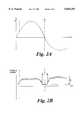
- FIGS. 2A and 2Brespectively show mains signal voltage and one example of noise power on one phase line of the system of FIG. 1 over a time period;
- FIGS. 3A and 3Brespectively show mains signal voltage and another example of noise power on one phase line of the system of FIG. 1 over a time period;
- FIG. 4shows an example of asymmetrically transmitting a data packet about a zero-crossing point
- FIG. 5shows an example of calculating the timing of quiet periods, based on zero-crossing points
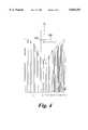
- FIG. 6Ashows three mains phase signals and FIGS. 6B, 6C, 6D show noise powers on each of the phase lines over a time period;
- FIG. 7Ashows an example of a data packet and FIG. 7B shows an example of transmitting a downstream packet and an upstream packet together during a quiet period;
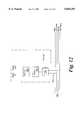
- FIG. 8shows the base station of FIG. 1 in more detail
- FIG. 9shows an alternative form of the base station of FIG. 8
- FIG. 10shows a method of operating the power line communications system using the base station of FIG. 9;
- FIG. 11shows one example of a scheme for allocating subscribers access to the distribution cable
- FIG. 12shows a typical subscriber station equipment in more detail.
- FIG. 1shows an electricity distribution network which is adapted to carry telecommunications signals.
- Mains electricityenters the network from an 11 kV or 6.6 kV transmission line 105 and is transformed by substation 100 into a 400V supply which is delivered over distribution cable 120 to subscriber stations S1 to S6.
- the subscriber stationsare typically located at houses or businesses.
- Distribution cable 120comprises blue, red and yellow phase lines and a neutral line.
- a full systemwill usually include more than the six subscriber stations shown here and will typically include a more elaborate tree-and-branch distribution network.
- Subscriber premisesmay receive a single phase electricity supply (230V) or a three-phase electricity supply (400V).
- domestic subscriber premisesusually receive a single phase supply and neighbouring subscriber premises are usually coupled to different phase lines.
- subscriber S1is shown coupled to the red phase line
- subscriber S2is coupled to the yellow phase line. This helps to distribute the load of the network evenly across the three phases.
- a base station BScouples data signals onto distribution cable 120.
- the communications signalspropagate over the cable to transceiver units at subscriber premises S1 to S6. Subscribers couple to a phase line of distribution cable 120 by a branch line 150.
- communications signalsare transmitted from the subscriber transceiver units towards the base station.
- Communications signalsare preferably transmitted between a phase line and neutral or earth.
- Datacan be transmitted using a variety of line coding or modulation techniques. Applicant uses Frequency Shift Keying (FSK) modulation about a centre-frequency of 2.9 MHz. Other frequency bands in the range of, for example, 2-30 MHz can be used although it is preferred to use the lower frequencies because attenuation over the distribution cables is lower.
- the upstream and downstream transmissionscan be time-division multiplexed, with the upstream and downstream transmissions sharing a common frequency band, or frequency-division multiplexed where the upstream and downstream transmissions occupy different frequency bands.
- FIG. 2Ais a plot of a typical mains waveform carried on one of the phase lines, showing voltage against time.
- FIG. 2Bis a plot of one example of noise power against time occurring during the corresponding time interval.
- Noise poweris not constant, but varies with time. It has been found that the noise power on the line varies according to the voltage of the mains signal. There are periods ⁇ when noise power is significantly reduced on the line, and at such times the reduction in noise power P D can be of the order of 20 dB. It has been found that much of the noise is caused by sparking across contacts. Sparking is an effect which is dependent upon voltage, and which is significantly reduced below certain voltages. Thermostats, switches and electric motors are examples of equipment which generate this form of noise.
- noise power envelopecan vary depending on the equipment coupled to the network at a particular time.
- the noise power envelopehas a frequency of 100 Hz, i.e. twice the mains frequency. Under other conditions, such as when the noise is dependent upon the polarity of the mains signal, the noise power envelope can have a frequency equal to the mains frequency. Under other conditions the noise envelope can have some other frequency.
- Data packetshave a duration which is equal to, or slightly shorter than, the quiet period and are transmitted so as to fit within the quiet period.
- the quiet perioddoes not have sharply-defined boundaries at which the noise level abruptly changes, but instead the noise level progressively increases each side of the mains zero-crossing point as shown by envelope 200 in FIG. 3B.
- This graphis an actual plot of noise generated by a faulty thermostat.
- a data packetcan be transmitted such that it is symmetrical about the zero-crossing point of the mains signal, or it can be transmitted such that it is asymmetrical about the zero-crossing point.
- Asymmetrical transmissionhas a particular use where access to the network is controlled by a token-passing protocol.
- a token-passing protocolit is particularly important that the token that is carried by data packets is not corrupted or lost.
- the tokenusually comprises a special bit pattern carried in an access burst and an address of the subscriber station to which the packet is destined.
- the packetcan be timed such that the majority of the packet is transmitted after the zero-crossing point such that the token is transmitted during the time at which noise is close to its minimum level.
- FIG. 4shows an example of transmitting a data packet 220 asymmetrically about the zero crossing-point t o , such that token 230 is transmitted at a time at which the noise power is at its minimum level.
- quiet periodsare known to be located about a characteristic feature of the power signal, such as the zero-crossing points
- Zero crossing pointscan be detected by using a voltage comparator which continually compares the line voltage with a reference value of zero volts.
- the quiet periodextends each side of the zero-crossing point and it is desired to make full use of the quiet period, it is necessary to predict when future zero-crossings will occur, and from that predicted time and the knowledge of the quiet window duration, to predict the time when the future quiet window will start. This is described with reference to FIG. 5.
- a 50 Hz mains signalhas zero-crossings t o occurring every 10 ms.
- a quiet windowlasts for 3 ms, divided equally about the zero-crossing point, it can be seen that a quiet window begins 1.5 ms before each zero-crossing point, or 8.5 ms after a zero-crossing point. Therefore, by detecting a zero-crossing point t o and waiting for 8.5 ms, a data packet can be transmitted at the beginning of the next quiet period.
- noise level on the lineIt is possible to measure actual noise level on the line and to use this measurement to vary the length of the quiet window.
- the measurements of noise powercan be analysed by techniques such as looking for excursions above particular threshold levels of noise power.
- FIG. 6Ais a plot of voltage against time for the power signals carried on the three phase lines Red, Yellow, Blue.
- the power signal on each phase lineis spaced apart by 120°.
- FIGS. 6B, 6C, 6Drespectively depict a plot of typical noise power against time for the Red, Yellow and Blue phase lines for the corresponding time interval.
- Quiet periods on the different phase linesare offset from one another in time by 120°, corresponding to the occurrence of the zero-crossing points on the lines. It can be seen that quiet periods successively occur on each phase line; in the example shown in FIGS. 6B-6D the sequence of quiet periods is blue, yellow, red, blue, yellow, red.
- Advantagecan be taken of the quiet periods by successively transmitting over each of the phase lines in synchronism with the quiet periods.
- FIG. 7Ashows one example of the structure of a data packet.
- the duration of the packetis shown as 3.3 ms, to correspond to a quiet period duration of 3.3 ms as discussed above, but it can have a different duration.
- the packetcomprises an alert burst (ALERT) which includes a special bit pattern, known by subscriber stations, an address of a subscriber station to which the packet is detined (DEST. ID), a data payload (DATA) and an end-of-transmission flag (EOT).
- ALERTalert burst
- DEST. IDan address of a subscriber station to which the packet is detined
- DATAdata payload
- EOTend-of-transmission flag
- FIG. 7Bshows a way in which a downstream packet from a base station to a particular subscriber station and an upstream packet from that subscriber station to the base station can be sent one after the other within a quiet period.
- the downstream packetis sent at the beginning of the quiet period and includes an alert burst (ALERT), address of the subscriber station (DEST.
- ALERTalert burst
- an upstream transmissioncomprising comprises an alert burst (ALERT), address of the base station (DEST. ID), a data payload (DATA) and an end-of-transmission flag (EOT).
- ALTRalert burst
- DEST. IDaddress of the base station
- DATAdata payload
- EOTend-of-transmission flag
- FIG. 8shows the base station BS of FIG. 1 in more detail.
- a branchis taken from each of the phase lines (Red, Yellow, Blue) and the neutral line.
- Each phase lineis coupled to a medium adapter unit MAU which comprises a high-pass filter to pass signals in the band used for communications and to block the flow of mains electricity at 50 Hz or 60 Hz.
- MAUalso includes amplifiers for individually adjusting the level of an upstream signal received from cable 120 and a downstream signal prior to transmission over cable 120.
- a combiner 301combines a received signal from each MAU for applying to LAN Hub transceiver, and a splitter 302 splits a signal output by the LAN hub transceiver three ways to apply a portion to each MAU for transmission over each phase line.
- LAN hub transceiverroutes data packets to the telecommunications network.
- the transceivercouples to external transmission network 320 and transports telecommunications signals to and from network 320.
- Blocks 340 and 350comprise the main equipment which is required for implementing transmission during quiet periods.
- a convenient way of monitoring a single phase lineis by incorporating a zero crossing detector 340 into the base station power supply unit PSU, which derives a single phase supply from the distribution cable.
- An output from detector 340is fed to controller 351.
- the controllercalculates the time when future quiet periods will occur on each of the phase lines, based on the known periodic nature of the a.c. signal and the known relationship between the phase lines. Updates from detector 340 on times when zero crossings actually occur allows the controller to maintain accurate predictions.
- a noise detector 345can be provided to monitor actual noise on the line and provide information to controller 351 for use in changing timing of quiet periods. Noise detector 345 in combination with controller 351 can be arranged to analyse the monitored noise on the line to detect a periodic noise pattern and to predict future quiet periods based on the identified pattern.
- Polling sequencer 352co-ordinates the order in which data subscribers on the network are polled, with reference to subscriber look-up table 353.
- the look-up tableis a memory with a list of each data subscriber and the phase line to which they are coupled.
- step 500the base station transmits a signal requesting that a particular subscriber station transmits a test signal.
- the subscriber stationresponds, at step 501, by transmitting a test signal.
- a bank of power detectors 400, one detector per phase line,are coupled to the outputs of the MAUs at the base station.
- a comparator 401compares the outputs of the detectors during reception of a test signal from a new subscriber.
- the base stationdetermines, from the detector outputs, which phase line provides the strongest signal and hence to which phase line the subscriber is coupled. This is entered, under the control of controller 351, into look-up table 353.
- a measurement other than signal strengthcan be used in determining the best phase line that a subscriber is coupled to; e.g. quantities such as bit error rate (BER) can be used.
- BERbit error rate
- the test signalshould be at the lower end of the frequency range used for transmission. This is because coupling between the phase lines generally decreases with transmission frequency.
- the polling sequenceradapts the manner in which data subscribers are polled according to demand from the users. Some scenarios will now be considered.
- FIG. 11illustrates how six subscribers S1-S6, coupled in the manner shown in FIG. 1, are polled. Subscribers S1 and S4 are coupled to the red phase line. During the quiet periods on red 601, 602, 603 subscribers S1 and S4 are polled, by transmitting data packets which are addressed to these subscribers. Quiet periods are shared among the subscribers on that phase. In this example alternate quiet periods on the red line are allocated to a particular subscriber, e.g. subscriber S1 is allocated slots 601 and 603.
- sequencerallocates timeslots preferentially to subscribers during quiet periods on the phase line to which they are connected, as in case (1).
- sequencerpreferentially allocates timeslots to correspond with quiet periods on the phase line to which subscribers are connected, but also allocates non-optimum slots.
- An examplewill illustrate this technique. Consider demand from two data subscribers: S1 on red phase, S2 on yellow phase and no demand from subscribers on blue.
- a possible polling sequenceis:
- Subscribers S1 (Red) and S2 (Yellow)are allocated quiet periods on the phase line to which they are connected and, in addition, the non-optimum periods on the blue phase line are alternately allocated to S1 and S2.
- FIG. 12shows a typical installation at a residence which subscribes to the data service.
- Branch cable 150represents a conventional mains branch cable which couples to one of the three phase lines in distribution cable 120.
- Coupling unit 700couples communications signals to and from cable 150, allowing the mains supply to pass.
- Medium adapter unit 710may include one or more amplifiers to adjust the level of signals in the upstream (transmit) and downstream (receive) directions.
- Transceiver 720receives data packets and converts them into an output data stream for coupling to equipment in the subscriber's home such as a personal computer which is accessing the Internet or a home-banking service. The transceiver also converts an incoming data stream into data packets which are transmitted to the base station.
- a variety of conventional local area network protocolscan be used on the network.
- a preferred protocolis token-passing bus, such as IEEE 802.4, ANSI 878.1 or Universal Serial Bus (USB).
- IEEE 802.4, ANSI 878.1 or Universal Serial Bus (USB)This is a disciplined access technique in which a token controls the right of access to the transmission medium. The token is passed from one subscriber to another in rotation. When a subscriber receives the token, in a packet which carries an address corresponding to the subscriber's own address, the subscriber identifies that it has the token and replies to the base station.
- the typical peak data rate of the systemis in the region of 1 Mbit/s.
Landscapes
- Engineering & Computer Science (AREA)
- Power Engineering (AREA)
- Computer Networks & Wireless Communication (AREA)
- Signal Processing (AREA)
- Cable Transmission Systems, Equalization Of Radio And Reduction Of Echo (AREA)
- Small-Scale Networks (AREA)
- Financial Or Insurance-Related Operations Such As Payment And Settlement (AREA)
- Management, Administration, Business Operations System, And Electronic Commerce (AREA)
- Radio Relay Systems (AREA)
Abstract
Description
______________________________________ Window on: R Y B R Y B . . . Subscriber: S1 S2 S1 S1 S2 S2 . . . ______________________________________
Claims (18)
Priority Applications (13)
| Application Number | Priority Date | Filing Date | Title |
|---|---|---|---|
| US08/871,930US5828293A (en) | 1997-06-10 | 1997-06-10 | Data transmission over a power line communications system |
| GBGB9805765.6AGB9805765D0 (en) | 1997-06-10 | 1998-03-17 | Data transmission over a power line communications system |
| PCT/GB1998/001666WO1998057439A1 (en) | 1997-06-10 | 1998-06-08 | Data transmission over a power line communications system |
| AT98925858TATE226770T1 (en) | 1997-06-10 | 1998-06-08 | DATA TRANSMISSION VIA MAINS LINE TRANSMISSION SYSTEM |
| DE69808958TDE69808958T2 (en) | 1997-06-10 | 1998-06-08 | DATA TRANSFER VIA NETWORK LINE TRANSMISSION SYSTEM |
| AU77827/98AAU7782798A (en) | 1997-06-10 | 1998-06-08 | Data transmission over a power line communications system |
| AT98925857TATE246416T1 (en) | 1997-06-10 | 1998-06-08 | DATA TRANSMISSION VIA A NETWORK MESSAGE TRANSMISSION SYSTEM |
| PCT/GB1998/001667WO1998057440A2 (en) | 1997-06-10 | 1998-06-08 | Data transmission over a power line communications system |
| DE69816819TDE69816819T2 (en) | 1997-06-10 | 1998-06-08 | DATA TRANSFER VIA A NETWORK MESSAGE TRANSMISSION SYSTEM |
| AU77828/98AAU7782898A (en) | 1997-06-10 | 1998-06-08 | Data transmission over a power line communications system |
| CA2290353ACA2290353C (en) | 1997-06-10 | 1998-06-08 | Data transmission over a power line communications system |
| EP98925858AEP1021866B1 (en) | 1997-06-10 | 1998-06-08 | Data transmission over a power line communications system |
| EP98925857AEP0988712B1 (en) | 1997-06-10 | 1998-06-08 | Data transmission over a power line communications system |
Applications Claiming Priority (1)
| Application Number | Priority Date | Filing Date | Title |
|---|---|---|---|
| US08/871,930US5828293A (en) | 1997-06-10 | 1997-06-10 | Data transmission over a power line communications system |
Publications (1)
| Publication Number | Publication Date |
|---|---|
| US5828293Atrue US5828293A (en) | 1998-10-27 |
Family
ID=25358471
Family Applications (1)
| Application Number | Title | Priority Date | Filing Date |
|---|---|---|---|
| US08/871,930Expired - LifetimeUS5828293A (en) | 1997-06-10 | 1997-06-10 | Data transmission over a power line communications system |
Country Status (7)
| Country | Link |
|---|---|
| US (1) | US5828293A (en) |
| EP (1) | EP0988712B1 (en) |
| AT (1) | ATE246416T1 (en) |
| AU (1) | AU7782798A (en) |
| CA (1) | CA2290353C (en) |
| DE (1) | DE69816819T2 (en) |
| WO (1) | WO1998057439A1 (en) |
Cited By (98)
| Publication number | Priority date | Publication date | Assignee | Title |
|---|---|---|---|---|
| US5977650A (en)* | 1998-03-17 | 1999-11-02 | Northern Telecom Limited | Transmitting communications signals over a power line network |
| US6006071A (en)* | 1998-01-12 | 1999-12-21 | Intersil Corporation | RF communications system operable in the presence of a repetitive interference source and related methods |
| GB2348787A (en)* | 1999-04-10 | 2000-10-11 | Roke Manor Research | Data transmission |
| US6256478B1 (en)* | 1999-02-18 | 2001-07-03 | Eastman Kodak Company | Dynamic packet sizing in an RF communications system |
| US6317031B1 (en)* | 1996-08-06 | 2001-11-13 | Nortel Networks Limited | Power line communications |
| US6377163B1 (en) | 2000-09-21 | 2002-04-23 | Home Touch Lighting Systems Llc | Power line communication circuit |
| US6473608B1 (en) | 1999-01-12 | 2002-10-29 | Powerdsine Ltd. | Structure cabling system |
| US6522626B1 (en)* | 1998-12-15 | 2003-02-18 | Nortel Networks Limited | Power line communications system and method of operation thereof |
| ES2186531A2 (en)* | 2001-04-19 | 2003-05-01 | Diseno Sistemas Silicio Sa | Method for multiple access and transmission in a point-to-multipoint system on an electrical network |
| US20030099076A1 (en)* | 1999-08-02 | 2003-05-29 | Shimon Elkayam | Integral board and module for power over LAN |
| US20030189495A1 (en)* | 2002-04-03 | 2003-10-09 | Pettler Peter R. | Method and system for controlling a selected electrical load in a building |
| RU2214052C2 (en)* | 2001-10-19 | 2003-10-10 | Гутин Клавдий Иосифович | Method for transmitting and receiving signals using three-phase power line |
| US20030217364A1 (en)* | 2002-05-17 | 2003-11-20 | Polanek Edward L. | System handling video, control signals and power |
| US20040037300A1 (en)* | 1999-01-12 | 2004-02-26 | Amir Lehr | Structure cabling system |
| US20040049321A1 (en)* | 1999-01-12 | 2004-03-11 | Amir Lehr | System for power delivery over data communication cabling infrastructure |
| KR100423869B1 (en)* | 2001-12-04 | 2004-03-22 | 주식회사 플레넷 | Overcoming noise method using adaptive twin carrier applying on power line communication |
| US20040067745A1 (en)* | 2002-10-02 | 2004-04-08 | Amperion, Inc. | Method and system for signal repeating in powerline communications |
| US20040109499A1 (en)* | 2002-11-06 | 2004-06-10 | Ambient Corporation | Controlling power output of a modem for power line communications |
| US6804496B1 (en)* | 1999-02-05 | 2004-10-12 | Appairent Technologies, Inc. | Communicating in the presence of periodic microwave noise |
| US20040227623A1 (en)* | 2003-05-07 | 2004-11-18 | Telkonet, Inc. | Network topology and packet routing method using low voltage power wiring |
| US20040233928A1 (en)* | 2003-05-07 | 2004-11-25 | Telkonet, Inc. | Network topology and packet routing method using low voltage power wiring |
| US20050046550A1 (en)* | 2001-10-02 | 2005-03-03 | Crenshaw Ralph E. | Method and apparatus for attaching power line communications to customer premises |
| US6933835B2 (en) | 2001-02-14 | 2005-08-23 | Current Technologies, Llc | Data communication over a power line |
| US6950567B2 (en) | 2001-02-14 | 2005-09-27 | Current Technologies, Llc | Method and apparatus for providing inductive coupling and decoupling of high-frequency, high-bandwidth data signals directly on and off of a high voltage power line |
| US6958680B2 (en) | 2000-04-14 | 2005-10-25 | Current Technologies, Llc | Power line communication system and method of using the same |
| US6965303B2 (en) | 2002-12-10 | 2005-11-15 | Current Technologies, Llc | Power line communication system and method |
| US6965302B2 (en) | 2000-04-14 | 2005-11-15 | Current Technologies, Llc | Power line communication system and method of using the same |
| US20050253690A1 (en)* | 2001-10-02 | 2005-11-17 | Telkonet Communications, Inc. | Method and apparatus for attaching power line communications to customer premises |
| US6977578B2 (en) | 2000-01-20 | 2005-12-20 | Current Technologies, Llc | Method of isolating data in a power line communications network |
| US6980090B2 (en) | 2002-12-10 | 2005-12-27 | Current Technologies, Llc | Device and method for coupling with electrical distribution network infrastructure to provide communications |
| US6980089B1 (en) | 2000-08-09 | 2005-12-27 | Current Technologies, Llc | Non-intrusive coupling to shielded power cable |
| US6980091B2 (en) | 2002-12-10 | 2005-12-27 | Current Technologies, Llc | Power line communication system and method of operating the same |
| US6982611B2 (en) | 2002-06-24 | 2006-01-03 | Current Technologies, Llc | Power line coupling device and method of using the same |
| US6998962B2 (en) | 2000-04-14 | 2006-02-14 | Current Technologies, Llc | Power line communication apparatus and method of using the same |
| WO2006022424A1 (en)* | 2004-08-27 | 2006-03-02 | Matsushita Electric Industrial Co., Ltd. | Transmission schedule constructing apparatus |
| US7046124B2 (en) | 2003-01-21 | 2006-05-16 | Current Technologies, Llc | Power line coupling device and method of using the same |
| US7053756B2 (en) | 2001-12-21 | 2006-05-30 | Current Technologies, Llc | Facilitating communication of data signals on electric power systems |
| US7064654B2 (en) | 2002-12-10 | 2006-06-20 | Current Technologies, Llc | Power line communication system and method of operating the same |
| US7075414B2 (en) | 2003-05-13 | 2006-07-11 | Current Technologies, Llc | Device and method for communicating data signals through multiple power line conductors |
| US7076378B1 (en)* | 2002-11-13 | 2006-07-11 | Current Technologies, Llc | Device and method for providing power line characteristics and diagnostics |
| US20060193313A1 (en)* | 2005-02-25 | 2006-08-31 | Telkonet, Inc. | Local area network above telephony infrastructure |
| US20060193336A1 (en)* | 2005-02-25 | 2006-08-31 | Telkonet, Inc. | Local area network above cable television methods and devices |
| US20060193310A1 (en)* | 2005-02-25 | 2006-08-31 | Telkonet, Inc. | Local area network above telephony methods and devices |
| US7102478B2 (en) | 2002-06-21 | 2006-09-05 | Current Technologies, Llc | Power line coupling device and method of using the same |
| US7113134B1 (en) | 2004-03-12 | 2006-09-26 | Current Technologies, Llc | Transformer antenna device and method of using the same |
| RU2285336C2 (en)* | 2004-05-05 | 2006-10-10 | Юрий Геннадьевич Чирков | Method for transmitting and receiving instructions over communication channel |
| US20060226958A1 (en)* | 2005-03-16 | 2006-10-12 | Domosys Corporation | System and method for power line communication |
| US7132819B1 (en) | 2002-11-12 | 2006-11-07 | Current Technologies, Llc | Floating power supply and method of using the same |
| WO2007004742A1 (en)* | 2005-07-05 | 2007-01-11 | Matsushita Electric Industrial Co., Ltd. | Communications device and communications method |
| US7199699B1 (en) | 2002-02-19 | 2007-04-03 | Current Technologies, Llc | Facilitating communication with power line communication devices |
| US20070189242A1 (en)* | 2004-04-05 | 2007-08-16 | Shuya Hosokawa | Wireless communication device and wireless communication method |
| US7308103B2 (en) | 2003-05-08 | 2007-12-11 | Current Technologies, Llc | Power line communication device and method of using the same |
| US7308233B2 (en) | 2002-10-10 | 2007-12-11 | Aster Wireless | System employing wideband wireless communication with super cycle detection |
| US20080114998A1 (en)* | 2006-11-12 | 2008-05-15 | Microsemi Corp. - Analog Mixed Signal Group Ltd. | Reduced Guard Band for Power Over Ethernet |
| US20080130673A1 (en)* | 2004-12-15 | 2008-06-05 | Smartlabs, Inc. | Network of intelligent devices communicating via powerline and radio frequency |
| USRE40492E1 (en) | 2000-02-10 | 2008-09-09 | Telkonet Communications, Inc. | Power line telephony exchange |
| US7447144B2 (en) | 2000-09-21 | 2008-11-04 | Serconet, Ltd. | Telephone communication system and method over local area network wiring |
| US7460467B1 (en) | 2003-07-23 | 2008-12-02 | Current Technologies, Llc | Voice-over-IP network test device and method |
| US20080301253A1 (en)* | 2007-06-01 | 2008-12-04 | Matsushita Electric Industrial Co., Ltd. | Communication method, communication apparatus, integrated circuit and circuit module |
| US20080304577A1 (en)* | 2007-05-30 | 2008-12-11 | Matsushita Electric Industrial Co., Ltd. | Power-line communication method, power-line communication device, and power-line communication system |
| US7522615B2 (en) | 2002-11-13 | 2009-04-21 | Serconet, Ltd. | Addressable outlet, and a network using same |
| US20090261651A1 (en)* | 2005-09-15 | 2009-10-22 | Rolf Godecke | Power Supply and Communications System for a Passenger Aircarft |
| US7609784B1 (en)* | 2004-04-26 | 2009-10-27 | Dgi Creations, Llc | Signal decoding method and apparatus with dynamic noise threshold |
| US20100030392A1 (en)* | 2008-07-31 | 2010-02-04 | Microsemi Corp. - Analog Mixed Signal Group Ltd. | Time Integrated Guard Band |
| US20100115299A1 (en)* | 2008-11-04 | 2010-05-06 | Microsemi Corp. - Analog Mixed Signal Group, Ltd. | Compensation for high powered midspan power sourcing equipment |
| US7715425B2 (en)* | 2004-02-26 | 2010-05-11 | Atheros Communications, Inc. | Channel adaptation synchronized to periodically varying channel |
| US7715534B2 (en) | 2000-03-20 | 2010-05-11 | Mosaid Technologies Incorporated | Telephone outlet for implementing a local area network over telephone lines and a local area network using such outlets |
| US7830858B2 (en) | 1998-07-28 | 2010-11-09 | Mosaid Technologies Incorporated | Local area network of serial intelligent cells |
| US7835386B2 (en) | 1999-07-07 | 2010-11-16 | Mosaid Technologies Incorporated | Local area network for distributing data communication, sensing and control signals |
| EP2270998A1 (en)* | 2009-07-02 | 2011-01-05 | Dora S.p.A. | Method and apparatus for communcating data over the power line |
| US7873058B2 (en) | 2004-11-08 | 2011-01-18 | Mosaid Technologies Incorporated | Outlet with analog signal adapter, a method for use thereof and a network using said outlet |
| US7876767B2 (en) | 2000-04-19 | 2011-01-25 | Mosaid Technologies Incorporated | Network combining wired and non-wired segments |
| US7881462B2 (en) | 2004-02-16 | 2011-02-01 | Mosaid Technologies Incorporated | Outlet add-on module |
| US20110246793A1 (en)* | 2010-04-01 | 2011-10-06 | Xyratex Technology Limited | Method of providing out of band monitoring and control of a data storage subsystem |
| US20110280261A1 (en)* | 2010-05-11 | 2011-11-17 | Texas Instruments Incorporated | Interleaver Design and Header Structure For ITU G.hnem |
| US8155012B2 (en) | 1998-04-10 | 2012-04-10 | Chrimar Systems, Inc. | System and method for adapting a piece of terminal equipment |
| CN102611481A (en)* | 2012-03-16 | 2012-07-25 | 北京福星晓程电子科技股份有限公司 | Power line carrier communication method and power line carrier communication system |
| US20130019036A1 (en)* | 2010-03-31 | 2013-01-17 | The Boeing Company | Expanded Electronic Bus Communication Capacity |
| US20130051268A1 (en)* | 2011-08-29 | 2013-02-28 | Texas Instruments Incorporated | Carrier Sense Multiple Access (CSMA) and Collision Detection for Power Line Communications (PLC) Using a Noise Model |
| US8410630B2 (en) | 2010-07-16 | 2013-04-02 | Lumenpulse Lighting Inc. | Powerline communication control of light emitting diode (LED) lighting fixtures |
| US8565292B2 (en) | 2007-10-12 | 2013-10-22 | Panasonic Corporation | Communication apparatus, integrated circuit, and communication method |
| US8761276B2 (en) | 2010-12-29 | 2014-06-24 | Hong Kong Applied Science and Technology Research Institute Company Limited | OFDM symbol structure for power line communication |
| US20140219369A1 (en)* | 2013-02-07 | 2014-08-07 | Flextronics Ap, Llc | Power line communications signal aggregation and switch |
| US8891605B2 (en) | 2013-03-13 | 2014-11-18 | Qualcomm Incorporated | Variable line cycle adaptation for powerline communications |
| US9094913B2 (en) | 2012-11-20 | 2015-07-28 | Georgia Tech Research Corporation | Wideband data and power transmission using pulse delay modulation |
| US9223009B1 (en)* | 2011-12-19 | 2015-12-29 | Lockheed Martin Corporation | Method and system for electromagnetic interference (EMI) mitigation using an auxiliary receiver |
| US20160091907A1 (en)* | 2014-09-29 | 2016-03-31 | Nxp B.V. | Power supply interface |
| US20160187962A1 (en)* | 2014-12-31 | 2016-06-30 | Echelon Corporation | Systems, Methods, and Apparatuses for Powerline Communication |
| US9667318B2 (en) | 2010-05-11 | 2017-05-30 | Texas Instruments Corporation | Device and frame structure for powerline communications |
| US20180032457A1 (en)* | 2016-07-26 | 2018-02-01 | Qualcomm Incorporated | Slave initiated interrupts for a communication bus |
| US10277229B2 (en) | 2014-04-25 | 2019-04-30 | Kohler Co. | Communication over generator bus |
| EP3448015A4 (en)* | 2016-04-22 | 2019-11-27 | Kowa Company, Ltd. | MULTIPLEXER AND IMAGE CAPTURE DEVICE PROVIDED WITH SAID MULTIPLEXER |
| US20200351389A1 (en)* | 2014-11-04 | 2020-11-05 | Texas Instruments Incorporated | Automatic Selection of MAC Protocol to Support Multiple Prime PLC Standards |
| US10886971B1 (en) | 2020-03-30 | 2021-01-05 | Red Rock Telecommunications, LLC | System and method for access broadband over power lines (BPL) using double alternating carrier and channel frequencies |
| US11032353B2 (en) | 2004-01-13 | 2021-06-08 | May Patents Ltd. | Information device |
| US11245437B2 (en) | 2018-01-12 | 2022-02-08 | University Of Illinois Chicago | Systems and methods for co-transmission of discrete power and data |
| US11473418B1 (en) | 2020-01-22 | 2022-10-18 | Vermeer Manufacturing Company | Horizontal directional drilling system and method |
| US11778715B2 (en) | 2020-12-23 | 2023-10-03 | Lmpg Inc. | Apparatus and method for powerline communication control of electrical devices |
Families Citing this family (5)
| Publication number | Priority date | Publication date | Assignee | Title |
|---|---|---|---|---|
| US8090857B2 (en) | 2003-11-24 | 2012-01-03 | Qualcomm Atheros, Inc. | Medium access control layer that encapsulates data from a plurality of received data units into a plurality of independently transmittable blocks |
| US7729372B2 (en) | 2005-07-27 | 2010-06-01 | Sharp Corporation | Communicating in a network that includes a medium having varying transmission characteristics |
| US8175190B2 (en) | 2005-07-27 | 2012-05-08 | Qualcomm Atheros, Inc. | Managing spectra of modulated signals in a communication network |
| US8112358B2 (en) | 2007-06-04 | 2012-02-07 | Qualcomm Atheros, Inc. | Authorizing customer premise equipment on a sub-network |
| RU2725756C1 (en)* | 2019-12-30 | 2020-07-06 | Федеральное государственное бюджетное образовательное учреждение высшего образования "Комсомольский-на-Амуре государственный университет" (ФГБОУ ВО "КнАГУ") | Method of transmitting information over ac power supply lines |
Citations (8)
| Publication number | Priority date | Publication date | Assignee | Title |
|---|---|---|---|---|
| US3895369A (en)* | 1972-12-27 | 1975-07-15 | Toshiharu Ono | Supervisory system for abnormal conditions |
| US4097692A (en)* | 1975-09-25 | 1978-06-27 | Zellweger, Ltd. | Method and apparatus for the two-way transmission of pulses |
| GB1600056A (en)* | 1978-03-14 | 1981-10-14 | Texas Instruments Ltd | Communication via an electricity supply main |
| US4528667A (en)* | 1982-04-22 | 1985-07-09 | Siemens Aktiengesellschaft | System for the transmission of information messages |
| US4755792A (en)* | 1985-06-13 | 1988-07-05 | Black & Decker Inc. | Security control system |
| JPH07226778A (en)* | 1994-02-16 | 1995-08-22 | Mitsubishi Electric Corp | Data reception method |
| US5491463A (en)* | 1993-06-28 | 1996-02-13 | Advanced Control Technologies, Inc. | Power line communication system |
| US5521491A (en)* | 1993-08-23 | 1996-05-28 | Echelon Corporation | Phase detecting device for determining phase angle between two electrical signals |
Family Cites Families (3)
| Publication number | Priority date | Publication date | Assignee | Title |
|---|---|---|---|---|
| JPS5866541A (en)* | 1981-10-15 | 1983-04-20 | 松下電工株式会社 | 3-phase power line carriage controller |
| JPH082038B2 (en)* | 1988-10-18 | 1996-01-10 | 大崎電気工業株式会社 | Carrier signal transmission / reception method |
| US5278862A (en)* | 1992-04-03 | 1994-01-11 | Intellon Corporation | Timing for spread-spectrum communication across noisy media |
- 1997
- 1997-06-10USUS08/871,930patent/US5828293A/ennot_activeExpired - Lifetime
- 1998
- 1998-06-08EPEP98925857Apatent/EP0988712B1/ennot_activeExpired - Lifetime
- 1998-06-08WOPCT/GB1998/001666patent/WO1998057439A1/enactiveIP Right Grant
- 1998-06-08DEDE69816819Tpatent/DE69816819T2/ennot_activeExpired - Lifetime
- 1998-06-08CACA2290353Apatent/CA2290353C/ennot_activeExpired - Fee Related
- 1998-06-08ATAT98925857Tpatent/ATE246416T1/ennot_activeIP Right Cessation
- 1998-06-08AUAU77827/98Apatent/AU7782798A/ennot_activeAbandoned
Patent Citations (8)
| Publication number | Priority date | Publication date | Assignee | Title |
|---|---|---|---|---|
| US3895369A (en)* | 1972-12-27 | 1975-07-15 | Toshiharu Ono | Supervisory system for abnormal conditions |
| US4097692A (en)* | 1975-09-25 | 1978-06-27 | Zellweger, Ltd. | Method and apparatus for the two-way transmission of pulses |
| GB1600056A (en)* | 1978-03-14 | 1981-10-14 | Texas Instruments Ltd | Communication via an electricity supply main |
| US4528667A (en)* | 1982-04-22 | 1985-07-09 | Siemens Aktiengesellschaft | System for the transmission of information messages |
| US4755792A (en)* | 1985-06-13 | 1988-07-05 | Black & Decker Inc. | Security control system |
| US5491463A (en)* | 1993-06-28 | 1996-02-13 | Advanced Control Technologies, Inc. | Power line communication system |
| US5521491A (en)* | 1993-08-23 | 1996-05-28 | Echelon Corporation | Phase detecting device for determining phase angle between two electrical signals |
| JPH07226778A (en)* | 1994-02-16 | 1995-08-22 | Mitsubishi Electric Corp | Data reception method |
Cited By (219)
| Publication number | Priority date | Publication date | Assignee | Title |
|---|---|---|---|---|
| US6317031B1 (en)* | 1996-08-06 | 2001-11-13 | Nortel Networks Limited | Power line communications |
| US6006071A (en)* | 1998-01-12 | 1999-12-21 | Intersil Corporation | RF communications system operable in the presence of a repetitive interference source and related methods |
| US5977650A (en)* | 1998-03-17 | 1999-11-02 | Northern Telecom Limited | Transmitting communications signals over a power line network |
| US9812825B2 (en) | 1998-04-10 | 2017-11-07 | Chrimar Systems, Inc. | Ethernet device |
| US8155012B2 (en) | 1998-04-10 | 2012-04-10 | Chrimar Systems, Inc. | System and method for adapting a piece of terminal equipment |
| US8902760B2 (en) | 1998-04-10 | 2014-12-02 | Chrimar Systems, Inc. | Network system and optional tethers |
| US8942107B2 (en) | 1998-04-10 | 2015-01-27 | Chrimar Systems, Inc. | Piece of ethernet terminal equipment |
| US9019838B2 (en) | 1998-04-10 | 2015-04-28 | Chrimar Systems, Inc. | Central piece of network equipment |
| US9049019B2 (en) | 1998-04-10 | 2015-06-02 | Chrimar Systems, Inc. | Network equipment and optional tether |
| US7852874B2 (en) | 1998-07-28 | 2010-12-14 | Mosaid Technologies Incorporated | Local area network of serial intelligent cells |
| US8908673B2 (en) | 1998-07-28 | 2014-12-09 | Conversant Intellectual Property Management Incorporated | Local area network of serial intelligent cells |
| US7978726B2 (en) | 1998-07-28 | 2011-07-12 | Mosaid Technologies Incorporated | Local area network of serial intelligent cells |
| US7986708B2 (en) | 1998-07-28 | 2011-07-26 | Mosaid Technologies Incorporated | Local area network of serial intelligent cells |
| US8325636B2 (en) | 1998-07-28 | 2012-12-04 | Mosaid Technologies Incorporated | Local area network of serial intelligent cells |
| US7830858B2 (en) | 1998-07-28 | 2010-11-09 | Mosaid Technologies Incorporated | Local area network of serial intelligent cells |
| US8867523B2 (en) | 1998-07-28 | 2014-10-21 | Conversant Intellectual Property Management Incorporated | Local area network of serial intelligent cells |
| US8885659B2 (en) | 1998-07-28 | 2014-11-11 | Conversant Intellectual Property Management Incorporated | Local area network of serial intelligent cells |
| US8885660B2 (en) | 1998-07-28 | 2014-11-11 | Conversant Intellectual Property Management Incorporated | Local area network of serial intelligent cells |
| US7969917B2 (en) | 1998-07-28 | 2011-06-28 | Mosaid Technologies Incorporated | Local area network of serial intelligent cells |
| US6522626B1 (en)* | 1998-12-15 | 2003-02-18 | Nortel Networks Limited | Power line communications system and method of operation thereof |
| US20040095917A1 (en)* | 1999-01-12 | 2004-05-20 | Amir Lehr | Structure cabling system |
| US7327743B2 (en) | 1999-01-12 | 2008-02-05 | Microsemi Corp—Analog Mixed Signal Group, Ltd. | Structure cabling system |
| US9823732B2 (en) | 1999-01-12 | 2017-11-21 | Cisco Technology Inc. | Power control subsystem with a plurality of current limit values |
| US7254734B2 (en) | 1999-01-12 | 2007-08-07 | Powerdsine, Ltd. - Microsemi Corporation | Structure cabling system |
| US20040049321A1 (en)* | 1999-01-12 | 2004-03-11 | Amir Lehr | System for power delivery over data communication cabling infrastructure |
| US20040037300A1 (en)* | 1999-01-12 | 2004-02-26 | Amir Lehr | Structure cabling system |
| US20040266492A1 (en)* | 1999-01-12 | 2004-12-30 | Amir Lehr | Power supply subsystem for powering a node over communication cabling |
| US20050003795A1 (en)* | 1999-01-12 | 2005-01-06 | Amir Lehr | Power supply subsystem for powering a node over communication cabling |
| US7305573B2 (en) | 1999-01-12 | 2007-12-04 | Microsemi Corp. - Analog Mixed Signal Group Ltd. | Determining whether characteristics of a local area network node allow it to receive power over communication cabling |
| US20050041800A1 (en)* | 1999-01-12 | 2005-02-24 | Amir Lehr | Method and apparatus for supplying power in a local area network |
| US7325150B2 (en) | 1999-01-12 | 2008-01-29 | Microsemi Corp.—Analog Mixed Signal Group, Ltd. | Combiner for power delivery over data communication cabling infrastructure |
| US20050049758A1 (en)* | 1999-01-12 | 2005-03-03 | Amir Lehr | Method and apparatus for power management in a local area network |
| US7257724B2 (en) | 1999-01-12 | 2007-08-14 | Powerdsine Ltd. - Microsemi Corporation | Method and apparatus for power management in a local area network |
| US20060091865A1 (en)* | 1999-01-12 | 2006-05-04 | Amir Lehr | Power control subsystem for powering a node over communication cabling |
| US6909943B2 (en) | 1999-01-12 | 2005-06-21 | Power Dsine, Ltd. | System for power delivery over data communication cabling infrastructure |
| US20050169297A1 (en)* | 1999-01-12 | 2005-08-04 | Amir Lehr | System for powering a switch over data communication cabling infrastructure |
| US20050169243A1 (en)* | 1999-01-12 | 2005-08-04 | Amir Lehr | Combiner for power delivery over data communication cabling infrastructure |
| US6473608B1 (en) | 1999-01-12 | 2002-10-29 | Powerdsine Ltd. | Structure cabling system |
| US7346785B2 (en) | 1999-01-12 | 2008-03-18 | Microsemi Corp. - Analog Mixed Signal Group Ltd. | Structure cabling system |
| US7421290B2 (en) | 1999-01-12 | 2008-09-02 | Microsemi Corp.—Analog Mixed Signal Group Ltd. | Power supply subsystem for powering a node over communication cabling |
| US7437217B2 (en) | 1999-01-12 | 2008-10-14 | Microsemi Corp. - Analog Mixed Signal Group Ltd. | Method and apparatus for supplying power in a local area network |
| US7466819B2 (en) | 1999-01-12 | 2008-12-16 | Microsemi Corp. | System for powering a switch over data communication cabling infrastructure |
| US8559996B2 (en) | 1999-01-12 | 2013-10-15 | Cisco Technology Inc. | Power control subsystem with a plurality of current limit values |
| US9606596B2 (en) | 1999-01-12 | 2017-03-28 | Cisco Technology Inc. | Power control subsystem with a plurality of current limit values |
| US7813752B2 (en) | 1999-01-12 | 2010-10-12 | Microsemi Corp. - Analog Mixed Signal Group Ltd. | Power control subsystem for powering a node over communication cabling |
| US20020191553A1 (en)* | 1999-01-12 | 2002-12-19 | Amir Lehr | Structure cabling system |
| US7006815B2 (en) | 1999-01-12 | 2006-02-28 | Powerdsine, Ltd. | Power supply subsystem for powering a node over communication cabling |
| US20070135155A1 (en)* | 1999-01-12 | 2007-06-14 | Amir Lehr | Power Control Subsystem with a Plurality of Current Limit Values |
| US6985713B2 (en) | 1999-01-12 | 2006-01-10 | Powerdsine, Ltd. | Data communication network providing power over network connections with node identification functionality |
| US20030036819A1 (en)* | 1999-01-12 | 2003-02-20 | Amir Lehr | Data communication network |
| US20050124298A1 (en)* | 1999-02-05 | 2005-06-09 | Appairent Technologies, Inc. | Communicating in the presence of periodic noise |
| US6804496B1 (en)* | 1999-02-05 | 2004-10-12 | Appairent Technologies, Inc. | Communicating in the presence of periodic microwave noise |
| US6256478B1 (en)* | 1999-02-18 | 2001-07-03 | Eastman Kodak Company | Dynamic packet sizing in an RF communications system |
| GB2348787B (en)* | 1999-04-10 | 2003-10-29 | Roke Manor Research | Improvements in or relating to data transmission |
| GB2348787A (en)* | 1999-04-10 | 2000-10-11 | Roke Manor Research | Data transmission |
| US7835386B2 (en) | 1999-07-07 | 2010-11-16 | Mosaid Technologies Incorporated | Local area network for distributing data communication, sensing and control signals |
| US8121132B2 (en) | 1999-07-07 | 2012-02-21 | Mosaid Technologies Incorporated | Local area network for distributing data communication, sensing and control signals |
| US8582598B2 (en) | 1999-07-07 | 2013-11-12 | Mosaid Technologies Incorporated | Local area network for distributing data communication, sensing and control signals |
| US20030099076A1 (en)* | 1999-08-02 | 2003-05-29 | Shimon Elkayam | Integral board and module for power over LAN |
| US7046983B2 (en) | 1999-08-02 | 2006-05-16 | Powerdsine, Ltd. | Integral board and module for power over LAN |
| US6977578B2 (en) | 2000-01-20 | 2005-12-20 | Current Technologies, Llc | Method of isolating data in a power line communications network |
| USRE40492E1 (en) | 2000-02-10 | 2008-09-09 | Telkonet Communications, Inc. | Power line telephony exchange |
| US8363797B2 (en) | 2000-03-20 | 2013-01-29 | Mosaid Technologies Incorporated | Telephone outlet for implementing a local area network over telephone lines and a local area network using such outlets |
| US7715534B2 (en) | 2000-03-20 | 2010-05-11 | Mosaid Technologies Incorporated | Telephone outlet for implementing a local area network over telephone lines and a local area network using such outlets |
| US8855277B2 (en) | 2000-03-20 | 2014-10-07 | Conversant Intellectual Property Managment Incorporated | Telephone outlet for implementing a local area network over telephone lines and a local area network using such outlets |
| US6998962B2 (en) | 2000-04-14 | 2006-02-14 | Current Technologies, Llc | Power line communication apparatus and method of using the same |
| US6958680B2 (en) | 2000-04-14 | 2005-10-25 | Current Technologies, Llc | Power line communication system and method of using the same |
| US6965302B2 (en) | 2000-04-14 | 2005-11-15 | Current Technologies, Llc | Power line communication system and method of using the same |
| US7307511B2 (en) | 2000-04-14 | 2007-12-11 | Current Technologies, Llc | Power line communication system and method |
| US7245212B2 (en) | 2000-04-14 | 2007-07-17 | Current Technologies, Llc | Power line communication apparatus and method of using the same |
| US8848725B2 (en) | 2000-04-19 | 2014-09-30 | Conversant Intellectual Property Management Incorporated | Network combining wired and non-wired segments |
| US8867506B2 (en) | 2000-04-19 | 2014-10-21 | Conversant Intellectual Property Management Incorporated | Network combining wired and non-wired segments |
| US8873586B2 (en) | 2000-04-19 | 2014-10-28 | Conversant Intellectual Property Management Incorporated | Network combining wired and non-wired segments |
| US8982904B2 (en) | 2000-04-19 | 2015-03-17 | Conversant Intellectual Property Management Inc. | Network combining wired and non-wired segments |
| US7876767B2 (en) | 2000-04-19 | 2011-01-25 | Mosaid Technologies Incorporated | Network combining wired and non-wired segments |
| US6980089B1 (en) | 2000-08-09 | 2005-12-27 | Current Technologies, Llc | Non-intrusive coupling to shielded power cable |
| US7480233B2 (en) | 2000-09-21 | 2009-01-20 | Serconet Ltd. | Telephone communication system and method over local area network wiring |
| US7489709B2 (en) | 2000-09-21 | 2009-02-10 | Serconet Ltd. | Telephone communication system and method over local area network wiring |
| US7447144B2 (en) | 2000-09-21 | 2008-11-04 | Serconet, Ltd. | Telephone communication system and method over local area network wiring |
| US7843799B2 (en) | 2000-09-21 | 2010-11-30 | Mosaid Technologies Incorporated | Telephone communication system and method over local area network wiring |
| US8817779B2 (en) | 2000-09-21 | 2014-08-26 | Conversant Intellectual Property Management Incorporated | Telephone communication system and method over local area network wiring |
| US6377163B1 (en) | 2000-09-21 | 2002-04-23 | Home Touch Lighting Systems Llc | Power line communication circuit |
| US8619538B2 (en) | 2000-09-21 | 2013-12-31 | Mosaid Technologies Incorporated | Communication system and method over local area network wiring |
| US7453352B2 (en) | 2001-02-14 | 2008-11-18 | Current Technologies, Llc | Data communication over a power line |
| US6933835B2 (en) | 2001-02-14 | 2005-08-23 | Current Technologies, Llc | Data communication over a power line |
| US7414518B2 (en) | 2001-02-14 | 2008-08-19 | Current Technologies, Llc | Power line communication device and method |
| US7103240B2 (en) | 2001-02-14 | 2006-09-05 | Current Technologies, Llc | Method and apparatus for providing inductive coupling and decoupling of high-frequency, high-bandwidth data signals directly on and off of a high voltage power line |
| US7218219B2 (en) | 2001-02-14 | 2007-05-15 | Current Technologies, Llc | Data communication over a power line |
| US7042351B2 (en) | 2001-02-14 | 2006-05-09 | Current Technologies, Llc | Data communication over a power line |
| US6950567B2 (en) | 2001-02-14 | 2005-09-27 | Current Technologies, Llc | Method and apparatus for providing inductive coupling and decoupling of high-frequency, high-bandwidth data signals directly on and off of a high voltage power line |
| ES2186531A2 (en)* | 2001-04-19 | 2003-05-01 | Diseno Sistemas Silicio Sa | Method for multiple access and transmission in a point-to-multipoint system on an electrical network |
| CN1309180C (en)* | 2001-04-19 | 2007-04-04 | 硅系统设计公司 | Method for multiple access and transmission in point-to-multipoint system on electrical network |
| EA005473B1 (en)* | 2001-04-19 | 2005-02-24 | Дисеньо Де Системас Эн Силисио, С.А. | Method for multiple access and transmission in a point-to-multipoint system over an electrical network |
| WO2002087104A3 (en)* | 2001-04-19 | 2003-10-30 | Diseno Sistemas Silicio Sa | Method for multiple access and transmission in a point-to-multipoint system over an electrical network |
| ES2186531B1 (en)* | 2001-04-19 | 2005-03-16 | Diseño De Sistemas En Silicio, S.A. | PROCEDURE FOR MULTIPLE AND MULTIPLE DATA TRANSMISSION FOR A MULTI-USER DIGITAL DATA TRANSMISSION SYSTEM POINT TO MULTIPOINT ON ELECTRICAL NETWORK. |
| US20050046550A1 (en)* | 2001-10-02 | 2005-03-03 | Crenshaw Ralph E. | Method and apparatus for attaching power line communications to customer premises |
| US20050253690A1 (en)* | 2001-10-02 | 2005-11-17 | Telkonet Communications, Inc. | Method and apparatus for attaching power line communications to customer premises |
| US7091831B2 (en) | 2001-10-02 | 2006-08-15 | Telkonet Communications, Inc. | Method and apparatus for attaching power line communications to customer premises |
| RU2214052C2 (en)* | 2001-10-19 | 2003-10-10 | Гутин Клавдий Иосифович | Method for transmitting and receiving signals using three-phase power line |
| KR100423869B1 (en)* | 2001-12-04 | 2004-03-22 | 주식회사 플레넷 | Overcoming noise method using adaptive twin carrier applying on power line communication |
| US7053756B2 (en) | 2001-12-21 | 2006-05-30 | Current Technologies, Llc | Facilitating communication of data signals on electric power systems |
| US7199699B1 (en) | 2002-02-19 | 2007-04-03 | Current Technologies, Llc | Facilitating communication with power line communication devices |
| US20030189495A1 (en)* | 2002-04-03 | 2003-10-09 | Pettler Peter R. | Method and system for controlling a selected electrical load in a building |
| US20030217364A1 (en)* | 2002-05-17 | 2003-11-20 | Polanek Edward L. | System handling video, control signals and power |
| US7339111B2 (en) | 2002-05-17 | 2008-03-04 | Nitek International, Llc | System handling video, control signals and power |
| US7193149B2 (en)* | 2002-05-17 | 2007-03-20 | Northern Information Technology, Inc. | System handling video, control signals and power |
| US20070163796A1 (en)* | 2002-05-17 | 2007-07-19 | Polanek Edward L | System handling video, control signals and power |
| US7102478B2 (en) | 2002-06-21 | 2006-09-05 | Current Technologies, Llc | Power line coupling device and method of using the same |
| US6982611B2 (en) | 2002-06-24 | 2006-01-03 | Current Technologies, Llc | Power line coupling device and method of using the same |
| US7224243B2 (en) | 2002-06-24 | 2007-05-29 | Current Technologies, Llc | Power line coupling device and method of using the same |
| US20040067745A1 (en)* | 2002-10-02 | 2004-04-08 | Amperion, Inc. | Method and system for signal repeating in powerline communications |
| US6993317B2 (en)* | 2002-10-02 | 2006-01-31 | Amperion, Inc. | Method and system for signal repeating in powerline communications |
| US7308233B2 (en) | 2002-10-10 | 2007-12-11 | Aster Wireless | System employing wideband wireless communication with super cycle detection |
| US20080057870A1 (en)* | 2002-10-10 | 2008-03-06 | Aster Wireless | System employing wideband wireless communication with super cycle detection |
| US7378944B2 (en)* | 2002-11-06 | 2008-05-27 | Ambient Corporation | Controlling power output of a modem for power line communications |
| US20040109499A1 (en)* | 2002-11-06 | 2004-06-10 | Ambient Corporation | Controlling power output of a modem for power line communications |
| US7132819B1 (en) | 2002-11-12 | 2006-11-07 | Current Technologies, Llc | Floating power supply and method of using the same |
| US7911992B2 (en) | 2002-11-13 | 2011-03-22 | Mosaid Technologies Incorporated | Addressable outlet, and a network using the same |
| US7522615B2 (en) | 2002-11-13 | 2009-04-21 | Serconet, Ltd. | Addressable outlet, and a network using same |
| US7990908B2 (en) | 2002-11-13 | 2011-08-02 | Mosaid Technologies Incorporated | Addressable outlet, and a network using the same |
| US8295185B2 (en) | 2002-11-13 | 2012-10-23 | Mosaid Technologies Inc. | Addressable outlet for use in wired local area network |
| US7076378B1 (en)* | 2002-11-13 | 2006-07-11 | Current Technologies, Llc | Device and method for providing power line characteristics and diagnostics |
| US6965303B2 (en) | 2002-12-10 | 2005-11-15 | Current Technologies, Llc | Power line communication system and method |
| US6980090B2 (en) | 2002-12-10 | 2005-12-27 | Current Technologies, Llc | Device and method for coupling with electrical distribution network infrastructure to provide communications |
| US7064654B2 (en) | 2002-12-10 | 2006-06-20 | Current Technologies, Llc | Power line communication system and method of operating the same |
| US7701325B2 (en) | 2002-12-10 | 2010-04-20 | Current Technologies, Llc | Power line communication apparatus and method of using the same |
| US7250848B2 (en) | 2002-12-10 | 2007-07-31 | Current Technologies, Llc | Power line communication apparatus and method of using the same |
| US7301440B2 (en) | 2002-12-10 | 2007-11-27 | Current Technologies, Llc | Power line communication system and method |
| US6980091B2 (en) | 2002-12-10 | 2005-12-27 | Current Technologies, Llc | Power line communication system and method of operating the same |
| US7046124B2 (en) | 2003-01-21 | 2006-05-16 | Current Technologies, Llc | Power line coupling device and method of using the same |
| US20040227623A1 (en)* | 2003-05-07 | 2004-11-18 | Telkonet, Inc. | Network topology and packet routing method using low voltage power wiring |
| US20040233928A1 (en)* | 2003-05-07 | 2004-11-25 | Telkonet, Inc. | Network topology and packet routing method using low voltage power wiring |
| US7308103B2 (en) | 2003-05-08 | 2007-12-11 | Current Technologies, Llc | Power line communication device and method of using the same |
| US7075414B2 (en) | 2003-05-13 | 2006-07-11 | Current Technologies, Llc | Device and method for communicating data signals through multiple power line conductors |
| US7460467B1 (en) | 2003-07-23 | 2008-12-02 | Current Technologies, Llc | Voice-over-IP network test device and method |
| US11032353B2 (en) | 2004-01-13 | 2021-06-08 | May Patents Ltd. | Information device |
| US7881462B2 (en) | 2004-02-16 | 2011-02-01 | Mosaid Technologies Incorporated | Outlet add-on module |
| US7715425B2 (en)* | 2004-02-26 | 2010-05-11 | Atheros Communications, Inc. | Channel adaptation synchronized to periodically varying channel |
| US7113134B1 (en) | 2004-03-12 | 2006-09-26 | Current Technologies, Llc | Transformer antenna device and method of using the same |
| US20070189242A1 (en)* | 2004-04-05 | 2007-08-16 | Shuya Hosokawa | Wireless communication device and wireless communication method |
| US7609784B1 (en)* | 2004-04-26 | 2009-10-27 | Dgi Creations, Llc | Signal decoding method and apparatus with dynamic noise threshold |
| RU2285336C2 (en)* | 2004-05-05 | 2006-10-10 | Юрий Геннадьевич Чирков | Method for transmitting and receiving instructions over communication channel |
| CN101010886B (en)* | 2004-08-27 | 2011-04-20 | 松下电器产业株式会社 | Transmission schedule constructing apparatus |
| US7920506B2 (en)* | 2004-08-27 | 2011-04-05 | Panasonic Corporation | Transmission schedule constructing apparatus |
| US20080095123A1 (en)* | 2004-08-27 | 2008-04-24 | Go Kuroda | Transmission Schedule Constructing Apparatus |
| WO2006022424A1 (en)* | 2004-08-27 | 2006-03-02 | Matsushita Electric Industrial Co., Ltd. | Transmission schedule constructing apparatus |
| US7873058B2 (en) | 2004-11-08 | 2011-01-18 | Mosaid Technologies Incorporated | Outlet with analog signal adapter, a method for use thereof and a network using said outlet |
| US8081649B2 (en)* | 2004-12-15 | 2011-12-20 | Daniel Cregg | Network of intelligent devices communicating via powerline and radio frequency |
| US20080130673A1 (en)* | 2004-12-15 | 2008-06-05 | Smartlabs, Inc. | Network of intelligent devices communicating via powerline and radio frequency |
| US20060193336A1 (en)* | 2005-02-25 | 2006-08-31 | Telkonet, Inc. | Local area network above cable television methods and devices |
| US20060193313A1 (en)* | 2005-02-25 | 2006-08-31 | Telkonet, Inc. | Local area network above telephony infrastructure |
| US20060193310A1 (en)* | 2005-02-25 | 2006-08-31 | Telkonet, Inc. | Local area network above telephony methods and devices |
| US8223880B2 (en)* | 2005-03-16 | 2012-07-17 | Analog Devices, B.V. | System and method for power line communication |
| US20060226958A1 (en)* | 2005-03-16 | 2006-10-12 | Domosys Corporation | System and method for power line communication |
| US8295390B2 (en) | 2005-07-05 | 2012-10-23 | Panasonic Corporation | Communications device and communications method |
| WO2007004742A1 (en)* | 2005-07-05 | 2007-01-11 | Matsushita Electric Industrial Co., Ltd. | Communications device and communications method |
| US7660365B2 (en) | 2005-07-05 | 2010-02-09 | Panasonic Corporation | Communications device and communications method |
| US20070160172A1 (en)* | 2005-07-05 | 2007-07-12 | Matsushita Electric Industrial Co., Ltd. | Communications device and communications method |
| CN101218756B (en)* | 2005-07-05 | 2012-02-01 | 松下电器产业株式会社 | Communication device and communication method |
| US8174145B2 (en)* | 2005-09-15 | 2012-05-08 | Airbus Operations Gmbh | Power supply and communications system for a passenger aircarft |
| US20090261651A1 (en)* | 2005-09-15 | 2009-10-22 | Rolf Godecke | Power Supply and Communications System for a Passenger Aircarft |
| US7895456B2 (en) | 2006-11-12 | 2011-02-22 | Microsemi Corp. - Analog Mixed Signal Group Ltd | Reduced guard band for power over Ethernet |
| US20080114998A1 (en)* | 2006-11-12 | 2008-05-15 | Microsemi Corp. - Analog Mixed Signal Group Ltd. | Reduced Guard Band for Power Over Ethernet |
| US20080304577A1 (en)* | 2007-05-30 | 2008-12-11 | Matsushita Electric Industrial Co., Ltd. | Power-line communication method, power-line communication device, and power-line communication system |
| US8121202B2 (en) | 2007-05-30 | 2012-02-21 | Panasonic Corporation | Power-line communication method, power-line communication device, and power-line communication system |
| US20080301253A1 (en)* | 2007-06-01 | 2008-12-04 | Matsushita Electric Industrial Co., Ltd. | Communication method, communication apparatus, integrated circuit and circuit module |
| US8971422B2 (en) | 2007-10-12 | 2015-03-03 | Panasonic Corporation | Communication apparatus, integrated circuit, and communication method |
| US8565292B2 (en) | 2007-10-12 | 2013-10-22 | Panasonic Corporation | Communication apparatus, integrated circuit, and communication method |
| US8711911B2 (en) | 2007-10-12 | 2014-04-29 | Panasonic Corporation | Communication apparatus, integrated circuit, and communication method |
| US20100030392A1 (en)* | 2008-07-31 | 2010-02-04 | Microsemi Corp. - Analog Mixed Signal Group Ltd. | Time Integrated Guard Band |
| US8160753B2 (en) | 2008-07-31 | 2012-04-17 | Microsemi Corp.—Analog Mixed Signal Group Ltd. | Time integrated guard band |
| US8195965B2 (en) | 2008-11-04 | 2012-06-05 | Microsemi Corp. - Analog Mixed Signal Group Ltd. | Compensation for high powered midspan power sourcing equipment |
| US20100115299A1 (en)* | 2008-11-04 | 2010-05-06 | Microsemi Corp. - Analog Mixed Signal Group, Ltd. | Compensation for high powered midspan power sourcing equipment |
| CN101944938A (en)* | 2009-07-02 | 2011-01-12 | 多拉股份公司 | In the method that is subjected to transmission digital data packet on the polyphase electric power line of impulse noise effect |
| EP2270998A1 (en)* | 2009-07-02 | 2011-01-05 | Dora S.p.A. | Method and apparatus for communcating data over the power line |
| US20110002400A1 (en)* | 2009-07-02 | 2011-01-06 | Dora S.P.A | Method of transmitting a packet of digital data over a poly-phase power line affected by impulsive noise |
| US8542754B2 (en)* | 2009-07-02 | 2013-09-24 | Dora S.P.A. | Method of transmitting a packet of digital data over a poly-phase power line affected by impulsive noise |
| US8812763B2 (en)* | 2010-03-31 | 2014-08-19 | The Boeing Company | Expanded electronic bus communication capacity |
| US20130019036A1 (en)* | 2010-03-31 | 2013-01-17 | The Boeing Company | Expanded Electronic Bus Communication Capacity |
| US20110246793A1 (en)* | 2010-04-01 | 2011-10-06 | Xyratex Technology Limited | Method of providing out of band monitoring and control of a data storage subsystem |
| US9667318B2 (en) | 2010-05-11 | 2017-05-30 | Texas Instruments Corporation | Device and frame structure for powerline communications |
| US20110280261A1 (en)* | 2010-05-11 | 2011-11-17 | Texas Instruments Incorporated | Interleaver Design and Header Structure For ITU G.hnem |
| US10141978B2 (en) | 2010-05-11 | 2018-11-27 | Texas Instruments Incorporated | Data encoder for power line communications |
| US11005530B2 (en) | 2010-05-11 | 2021-05-11 | Texas Instruments Incorporated | Data encoder for power line communications |
| US10541727B2 (en) | 2010-05-11 | 2020-01-21 | Texas Instruments Incorporated | Data encoder for power line communications |
| US9819392B2 (en) | 2010-05-11 | 2017-11-14 | Texas Instruments Incorporated | Data encoder for power line communications |
| US9112753B2 (en)* | 2010-05-11 | 2015-08-18 | Texas Instruments Incorporated | Interleaver design and header structure for ITU G.hnem |
| US11791862B2 (en) | 2010-05-11 | 2023-10-17 | Texas Instruments Incorporated | Data encoder for power line communications |
| US8759999B2 (en) | 2010-07-16 | 2014-06-24 | Lumenpulse Lighting, Inc. | Powerline communication control of light emitting diode (LED) lighting fixtures |
| US9307619B2 (en) | 2010-07-16 | 2016-04-05 | Lumenopulse Lighting Inc. | Powerline communication control of light emitting diode (LED) lighting fixtures |
| US10462879B2 (en) | 2010-07-16 | 2019-10-29 | Lumenpulse Group Inc. | Powerline communication control of light emitting diode (LED) lighting fixtures |
| US8410630B2 (en) | 2010-07-16 | 2013-04-02 | Lumenpulse Lighting Inc. | Powerline communication control of light emitting diode (LED) lighting fixtures |
| US9024464B2 (en) | 2010-07-16 | 2015-05-05 | Lumenpulse Lighting Inc. | Powerline communication control of light emitting diode (LED) lighting fixtures |
| US9622329B2 (en) | 2010-07-16 | 2017-04-11 | Lumenpulse Lighting Inc. | Powerline communication control of light emitting diode (LED) lighting fixtures |
| US8761276B2 (en) | 2010-12-29 | 2014-06-24 | Hong Kong Applied Science and Technology Research Institute Company Limited | OFDM symbol structure for power line communication |
| US20130051268A1 (en)* | 2011-08-29 | 2013-02-28 | Texas Instruments Incorporated | Carrier Sense Multiple Access (CSMA) and Collision Detection for Power Line Communications (PLC) Using a Noise Model |
| US9223009B1 (en)* | 2011-12-19 | 2015-12-29 | Lockheed Martin Corporation | Method and system for electromagnetic interference (EMI) mitigation using an auxiliary receiver |
| CN102611481A (en)* | 2012-03-16 | 2012-07-25 | 北京福星晓程电子科技股份有限公司 | Power line carrier communication method and power line carrier communication system |
| CN102611481B (en)* | 2012-03-16 | 2016-04-27 | 北京晓程科技股份有限公司 | A kind of power-line carrier communication method and system thereof |
| US9094913B2 (en) | 2012-11-20 | 2015-07-28 | Georgia Tech Research Corporation | Wideband data and power transmission using pulse delay modulation |
| US20140219369A1 (en)* | 2013-02-07 | 2014-08-07 | Flextronics Ap, Llc | Power line communications signal aggregation and switch |
| US8891605B2 (en) | 2013-03-13 | 2014-11-18 | Qualcomm Incorporated | Variable line cycle adaptation for powerline communications |
| US10277229B2 (en) | 2014-04-25 | 2019-04-30 | Kohler Co. | Communication over generator bus |
| US9568926B2 (en)* | 2014-09-29 | 2017-02-14 | Nxp B.V. | Power supply interface having multiple voltage sources |
| US20160091907A1 (en)* | 2014-09-29 | 2016-03-31 | Nxp B.V. | Power supply interface |
| US20200351389A1 (en)* | 2014-11-04 | 2020-11-05 | Texas Instruments Incorporated | Automatic Selection of MAC Protocol to Support Multiple Prime PLC Standards |
| US11985215B2 (en)* | 2014-11-04 | 2024-05-14 | Texas Instruments Incorporated | Automatic selection of MAC protocol to support multiple prime PLC standards |
| US10474223B2 (en)* | 2014-12-31 | 2019-11-12 | Echelon Corporation | Systems, methods, and apparatuses for powerline communication |
| US20160187962A1 (en)* | 2014-12-31 | 2016-06-30 | Echelon Corporation | Systems, Methods, and Apparatuses for Powerline Communication |
| US11353947B2 (en)* | 2014-12-31 | 2022-06-07 | Echelon Corporation | Systems, methods, and apparatuses for powerline communication |
| EP3448015A4 (en)* | 2016-04-22 | 2019-11-27 | Kowa Company, Ltd. | MULTIPLEXER AND IMAGE CAPTURE DEVICE PROVIDED WITH SAID MULTIPLEXER |
| US20180032457A1 (en)* | 2016-07-26 | 2018-02-01 | Qualcomm Incorporated | Slave initiated interrupts for a communication bus |
| US11245437B2 (en) | 2018-01-12 | 2022-02-08 | University Of Illinois Chicago | Systems and methods for co-transmission of discrete power and data |
| US12348281B2 (en) | 2018-01-12 | 2025-07-01 | The Board Of Trustees Of The University Of Illinois | Systems and methods for co-transmission of discrete power and data |
| US12352152B2 (en) | 2020-01-22 | 2025-07-08 | Vermeer Manufacturing Company | Horizontal directional drilling system and method |
| US11473418B1 (en) | 2020-01-22 | 2022-10-18 | Vermeer Manufacturing Company | Horizontal directional drilling system and method |
| US11927090B2 (en) | 2020-01-22 | 2024-03-12 | Vermeer Manufacturing Company | Horizontal directional drilling system and method |
| US10886971B1 (en) | 2020-03-30 | 2021-01-05 | Red Rock Telecommunications, LLC | System and method for access broadband over power lines (BPL) using double alternating carrier and channel frequencies |
| US11778715B2 (en) | 2020-12-23 | 2023-10-03 | Lmpg Inc. | Apparatus and method for powerline communication control of electrical devices |
Also Published As
| Publication number | Publication date |
|---|---|
| ATE246416T1 (en) | 2003-08-15 |
| CA2290353C (en) | 2010-05-04 |
| EP0988712A1 (en) | 2000-03-29 |
| WO1998057439A1 (en) | 1998-12-17 |
| AU7782798A (en) | 1998-12-30 |
| DE69816819T2 (en) | 2004-03-04 |
| EP0988712B1 (en) | 2003-07-30 |
| CA2290353A1 (en) | 1998-12-17 |
| DE69816819D1 (en) | 2003-09-04 |
Similar Documents
| Publication | Publication Date | Title |
|---|---|---|
| US5828293A (en) | Data transmission over a power line communications system | |
| EP1021866B1 (en) | Data transmission over a power line communications system | |
| US11431381B2 (en) | Optimized PHY frame structure for OFDM based narrowband PLC | |
| CN1758560B (en) | Power line communication methods | |
| EP2294721B1 (en) | Managing coexistence among signaling protocols on a shared medium | |
| US8258649B2 (en) | Communicating over power distribution media | |
| US7804763B2 (en) | Power line communication device and method | |
| US8879644B2 (en) | Power line communications method and apparatus | |
| US6522626B1 (en) | Power line communications system and method of operation thereof | |
| US8306090B2 (en) | Power line communication using frequency hopping | |
| US7158013B2 (en) | Detection of broadcast signals for defining useable frequency bands for powerline communication | |
| EP1014640A2 (en) | Multicarrier transmission on power lines | |
| US10218545B2 (en) | Power line communication device and method | |
| Dodds et al. | Power line communication using timed transmission |
Legal Events
| Date | Code | Title | Description |
|---|---|---|---|
| AS | Assignment | Owner name:NORTHERN TELECOM LIMITED WORLD TRADE CENTER OF MON Free format text:ASSIGNMENT OF ASSIGNORS INTEREST;ASSIGNOR:RICKARD, ROBIN PAUL;REEL/FRAME:008594/0703 Effective date:19970605 | |
| STCF | Information on status: patent grant | Free format text:PATENTED CASE | |
| AS | Assignment | Owner name:NORTEL NETWORKS CORPORATION, CANADA Free format text:CHANGE OF NAME;ASSIGNOR:NORTHERN TELECOM LIMITED;REEL/FRAME:010567/0001 Effective date:19990429 | |
| AS | Assignment | Owner name:NORTEL NETWORKS LIMITED, CANADA Free format text:CHANGE OF NAME;ASSIGNOR:NORTEL NETWORKS CORPORATION;REEL/FRAME:011195/0706 Effective date:20000830 Owner name:NORTEL NETWORKS LIMITED,CANADA Free format text:CHANGE OF NAME;ASSIGNOR:NORTEL NETWORKS CORPORATION;REEL/FRAME:011195/0706 Effective date:20000830 | |
| FPAY | Fee payment | Year of fee payment:4 | |
| FPAY | Fee payment | Year of fee payment:8 | |
| FPAY | Fee payment | Year of fee payment:12 | |
| AS | Assignment | Owner name:NORTHERN TELECOM LIMITED, CANADA Free format text:CORRECTIVE ASSIGNMENT TO CORRECT THE NAME OF THE RECEIVING PARTY TO REMOVE THE ADDRESS FROM THE NAME PREVIOUSLY RECORDED ON REEL 008594 FRAME 0703. ASSIGNOR(S) HEREBY CONFIRMS THE NAME OF THE RECEIVING PARTY IS NORTHERN TELECOM LIMITED;ASSIGNOR:RICKARD, ROBIN PAUL;REEL/FRAME:026131/0438 Effective date:19970605 | |
| AS | Assignment | Owner name:ROCKSTAR BIDCO, LP, NEW YORK Free format text:ASSIGNMENT OF ASSIGNORS INTEREST;ASSIGNOR:NORTEL NETWORKS LIMITED;REEL/FRAME:027164/0356 Effective date:20110729 | |
| AS | Assignment | Owner name:ROCKSTAR CONSORTIUM US LP, TEXAS Free format text:ASSIGNMENT OF ASSIGNORS INTEREST;ASSIGNOR:ROCKSTAR BIDCO, LP;REEL/FRAME:032389/0800 Effective date:20120509 | |
| AS | Assignment | Owner name:RPX CLEARINGHOUSE LLC, CALIFORNIA Free format text:ASSIGNMENT OF ASSIGNORS INTEREST;ASSIGNORS:ROCKSTAR CONSORTIUM US LP;ROCKSTAR CONSORTIUM LLC;BOCKSTAR TECHNOLOGIES LLC;AND OTHERS;REEL/FRAME:034924/0779 Effective date:20150128 | |
| AS | Assignment | Owner name:JPMORGAN CHASE BANK, N.A., AS COLLATERAL AGENT, IL Free format text:SECURITY AGREEMENT;ASSIGNORS:RPX CORPORATION;RPX CLEARINGHOUSE LLC;REEL/FRAME:038041/0001 Effective date:20160226 | |
| AS | Assignment | Owner name:RPX CLEARINGHOUSE LLC, CALIFORNIA Free format text:RELEASE (REEL 038041 / FRAME 0001);ASSIGNOR:JPMORGAN CHASE BANK, N.A.;REEL/FRAME:044970/0030 Effective date:20171222 Owner name:RPX CORPORATION, CALIFORNIA Free format text:RELEASE (REEL 038041 / FRAME 0001);ASSIGNOR:JPMORGAN CHASE BANK, N.A.;REEL/FRAME:044970/0030 Effective date:20171222 |