US5827478A - Incubation chamber - Google Patents
Incubation chamberDownload PDFInfo
- Publication number
- US5827478A US5827478AUS08/742,230US74223096AUS5827478AUS 5827478 AUS5827478 AUS 5827478AUS 74223096 AUS74223096 AUS 74223096AUS 5827478 AUS5827478 AUS 5827478A
- Authority
- US
- United States
- Prior art keywords
- cuvette
- ring
- magnet
- cuvettes
- sample
- Prior art date
- Legal status (The legal status is an assumption and is not a legal conclusion. Google has not performed a legal analysis and makes no representation as to the accuracy of the status listed.)
- Expired - Lifetime
Links
Images


Classifications
- B—PERFORMING OPERATIONS; TRANSPORTING
- B01—PHYSICAL OR CHEMICAL PROCESSES OR APPARATUS IN GENERAL
- B01L—CHEMICAL OR PHYSICAL LABORATORY APPARATUS FOR GENERAL USE
- B01L3/00—Containers or dishes for laboratory use, e.g. laboratory glassware; Droppers
- B01L3/50—Containers for the purpose of retaining a material to be analysed, e.g. test tubes
- B01L3/508—Containers for the purpose of retaining a material to be analysed, e.g. test tubes rigid containers not provided for above
- B01L3/5085—Containers for the purpose of retaining a material to be analysed, e.g. test tubes rigid containers not provided for above for multiple samples, e.g. microtitration plates
- B01L3/50853—Containers for the purpose of retaining a material to be analysed, e.g. test tubes rigid containers not provided for above for multiple samples, e.g. microtitration plates with covers or lids
- G—PHYSICS
- G01—MEASURING; TESTING
- G01N—INVESTIGATING OR ANALYSING MATERIALS BY DETERMINING THEIR CHEMICAL OR PHYSICAL PROPERTIES
- G01N33/00—Investigating or analysing materials by specific methods not covered by groups G01N1/00 - G01N31/00
- G01N33/48—Biological material, e.g. blood, urine; Haemocytometers
- G01N33/50—Chemical analysis of biological material, e.g. blood, urine; Testing involving biospecific ligand binding methods; Immunological testing
- G01N33/53—Immunoassay; Biospecific binding assay; Materials therefor
- G—PHYSICS
- G01—MEASURING; TESTING
- G01N—INVESTIGATING OR ANALYSING MATERIALS BY DETERMINING THEIR CHEMICAL OR PHYSICAL PROPERTIES
- G01N35/00—Automatic analysis not limited to methods or materials provided for in any single one of groups G01N1/00 - G01N33/00; Handling materials therefor
- G01N35/00584—Control arrangements for automatic analysers
- G01N35/0092—Scheduling
- G—PHYSICS
- G01—MEASURING; TESTING
- G01N—INVESTIGATING OR ANALYSING MATERIALS BY DETERMINING THEIR CHEMICAL OR PHYSICAL PROPERTIES
- G01N35/00—Automatic analysis not limited to methods or materials provided for in any single one of groups G01N1/00 - G01N33/00; Handling materials therefor
- G01N35/0098—Automatic analysis not limited to methods or materials provided for in any single one of groups G01N1/00 - G01N33/00; Handling materials therefor involving analyte bound to insoluble magnetic carrier, e.g. using magnetic separation
- G—PHYSICS
- G01—MEASURING; TESTING
- G01N—INVESTIGATING OR ANALYSING MATERIALS BY DETERMINING THEIR CHEMICAL OR PHYSICAL PROPERTIES
- G01N35/00—Automatic analysis not limited to methods or materials provided for in any single one of groups G01N1/00 - G01N33/00; Handling materials therefor
- G01N35/02—Automatic analysis not limited to methods or materials provided for in any single one of groups G01N1/00 - G01N33/00; Handling materials therefor using a plurality of sample containers moved by a conveyor system past one or more treatment or analysis stations
- G01N35/025—Automatic analysis not limited to methods or materials provided for in any single one of groups G01N1/00 - G01N33/00; Handling materials therefor using a plurality of sample containers moved by a conveyor system past one or more treatment or analysis stations having a carousel or turntable for reaction cells or cuvettes
- G—PHYSICS
- G01—MEASURING; TESTING
- G01N—INVESTIGATING OR ANALYSING MATERIALS BY DETERMINING THEIR CHEMICAL OR PHYSICAL PROPERTIES
- G01N35/00—Automatic analysis not limited to methods or materials provided for in any single one of groups G01N1/00 - G01N33/00; Handling materials therefor
- G01N35/02—Automatic analysis not limited to methods or materials provided for in any single one of groups G01N1/00 - G01N33/00; Handling materials therefor using a plurality of sample containers moved by a conveyor system past one or more treatment or analysis stations
- G01N35/04—Details of the conveyor system
- G01N2035/0439—Rotary sample carriers, i.e. carousels
- G01N2035/0453—Multiple carousels working in parallel
- G01N2035/0455—Coaxial carousels
- Y—GENERAL TAGGING OF NEW TECHNOLOGICAL DEVELOPMENTS; GENERAL TAGGING OF CROSS-SECTIONAL TECHNOLOGIES SPANNING OVER SEVERAL SECTIONS OF THE IPC; TECHNICAL SUBJECTS COVERED BY FORMER USPC CROSS-REFERENCE ART COLLECTIONS [XRACs] AND DIGESTS
- Y10—TECHNICAL SUBJECTS COVERED BY FORMER USPC
- Y10T—TECHNICAL SUBJECTS COVERED BY FORMER US CLASSIFICATION
- Y10T436/00—Chemistry: analytical and immunological testing
- Y10T436/11—Automated chemical analysis
- Y10T436/113332—Automated chemical analysis with conveyance of sample along a test line in a container or rack
- Y10T436/114998—Automated chemical analysis with conveyance of sample along a test line in a container or rack with treatment or replacement of aspirator element [e.g., cleaning, etc.]
- Y—GENERAL TAGGING OF NEW TECHNOLOGICAL DEVELOPMENTS; GENERAL TAGGING OF CROSS-SECTIONAL TECHNOLOGIES SPANNING OVER SEVERAL SECTIONS OF THE IPC; TECHNICAL SUBJECTS COVERED BY FORMER USPC CROSS-REFERENCE ART COLLECTIONS [XRACs] AND DIGESTS
- Y10—TECHNICAL SUBJECTS COVERED BY FORMER USPC
- Y10T—TECHNICAL SUBJECTS COVERED BY FORMER US CLASSIFICATION
- Y10T436/00—Chemistry: analytical and immunological testing
- Y10T436/11—Automated chemical analysis
- Y10T436/115831—Condition or time responsive
- Y—GENERAL TAGGING OF NEW TECHNOLOGICAL DEVELOPMENTS; GENERAL TAGGING OF CROSS-SECTIONAL TECHNOLOGIES SPANNING OVER SEVERAL SECTIONS OF THE IPC; TECHNICAL SUBJECTS COVERED BY FORMER USPC CROSS-REFERENCE ART COLLECTIONS [XRACs] AND DIGESTS
- Y10—TECHNICAL SUBJECTS COVERED BY FORMER USPC
- Y10T—TECHNICAL SUBJECTS COVERED BY FORMER US CLASSIFICATION
- Y10T436/00—Chemistry: analytical and immunological testing
- Y10T436/11—Automated chemical analysis
- Y10T436/119163—Automated chemical analysis with aspirator of claimed structure
- Y—GENERAL TAGGING OF NEW TECHNOLOGICAL DEVELOPMENTS; GENERAL TAGGING OF CROSS-SECTIONAL TECHNOLOGIES SPANNING OVER SEVERAL SECTIONS OF THE IPC; TECHNICAL SUBJECTS COVERED BY FORMER USPC CROSS-REFERENCE ART COLLECTIONS [XRACs] AND DIGESTS
- Y10—TECHNICAL SUBJECTS COVERED BY FORMER USPC
- Y10T—TECHNICAL SUBJECTS COVERED BY FORMER US CLASSIFICATION
- Y10T436/00—Chemistry: analytical and immunological testing
- Y10T436/25—Chemistry: analytical and immunological testing including sample preparation
- Y10T436/25125—Digestion or removing interfering materials
- Y—GENERAL TAGGING OF NEW TECHNOLOGICAL DEVELOPMENTS; GENERAL TAGGING OF CROSS-SECTIONAL TECHNOLOGIES SPANNING OVER SEVERAL SECTIONS OF THE IPC; TECHNICAL SUBJECTS COVERED BY FORMER USPC CROSS-REFERENCE ART COLLECTIONS [XRACs] AND DIGESTS
- Y10—TECHNICAL SUBJECTS COVERED BY FORMER USPC
- Y10T—TECHNICAL SUBJECTS COVERED BY FORMER US CLASSIFICATION
- Y10T436/00—Chemistry: analytical and immunological testing
- Y10T436/25—Chemistry: analytical and immunological testing including sample preparation
- Y10T436/2575—Volumetric liquid transfer
Definitions
- This inventionrelates to automated immunoassay analyzer systems and more particularly to incubation chambers used in such systems.
- the samplesare typically placed in a container such as a sample cup or a primary tube for example, which is then placed in the analyzer system.
- a containersuch as a sample cup or a primary tube for example
- One or more appropriate chemical reagents needed to perform the assaysare also placed in the analyzer system.
- the reagentsare typically mixed with the samples in the analyzer system via a fluid moving system generally provided as a pipette controlled by a robotic arm.
- the pipetteis adapted to aspirate portions of the reagents and/or samples and dispense them into appropriate ones of the cuvettes where a reaction can take place.
- an automated immunoassay analyzer instrumentincludes a continuous closed loop incubation chamber and a plurality of processing centers disposed about the incubation chamber with each of the plurality of processing centers for aspiration and dispensing of at least one of specimen samples, reagents, and wash fluids.
- the incubation chamberincludes a continuous closed loop cuvette track for moving cuvettes in first and second opposite directions around the incubation chamber such that particular ones of plural cuvette slot positions in the cuvette track are positioned proximate particular ones of the plurality of processing centers at predetermined periods of time during a predefined cycle time.
- an automated random access immunoassay analyzer instrumentcapable of performing a plurality of different assays each of such assays having different protocols.
- the incubation chamberas a continuous loop, different incubation times may be accommodated by allowing an assay in a cuvette to complete multiple revolutions around the incubation chamber.
- the motion sequence of the cuvette trackcan be adjusted to accommodate different assay requirements. For example, specimen samples and reagents may be added to cuvettes at times selected to adjust the incubation time of the cuvette.
- the automated immunoassay analyzer instrumentfurther includes a continuous closed loop magnet track to which the cuvette track is movably coupled to thus provide the incubation chamber as an incubation and particle separation chamber in which paramagnetic particle separation may be performed in each of the cuvettes.
- the cuvette track and magnet trackare each provided having circular or ring shapes to thus provide the incubation and particle separation chamber as a rotary incubation and particle separation chamber.
- the assaysmay be processed by a scheduler in the analyzer instrument on a first-in-first-out (FIFO) basis or alternatively the process scheduler may be used to determine a particular order in which particular tests should be performed to thus maximize throughput of the analyzer system. In this manner the system is capable of processing a large number of assays in a predetermined period of time. For example, in one embodiment, the system can process about two-hundred and forty assays per hour.
- an automated immunoassay analyzer instrumentincludes a magnet ring having a magnet assembly coupled thereto, a cuvette ring movably coupled to the magnet ring and a drive system coupled to the magnet ring for moving the magnet ring in first and second opposite directions.
- an automated immunoassay analyzer instrumentfor performing multiple protocol assays including paramagnetic particle separation assays is provided.
- cuvettes containing assaysare moved past the magnet assembly. Paramagnetic particles in the cuvette are attracted to one region of the cuvette by a magnetic force provided from the magnet assembly to thus perform paramagnetic particle separation.
- the drive systemincludes a servo motor coupled to the magnet ring by a belt.
- the servo motorturns the belt to drive the magnet ring at high speeds.
- the servo motormay precisely position each of the cuvettes in the cuvette ring at predetermined points around the incubation chamber.
- the steel drive beltcan be pinned to the magnet ring to thus minimize slippage between the drive belt and magnet ring and thus allow the magnet ring to be driven at high speeds while still maintaining the ability to accurately position the magnet ring at predetermined locations around the incubation chamber.
- the steel beltcan be coupled to the magnet ring via friction.
- the cuvette ringcan be coupled to the magnet ring via a detent pin which locks the cuvette ring to the magnet ring.
- the analyzer instrumentfurther includes an index mechanism for disengaging the detent pin to thus allow the cuvette ring to move relative the magnet ring.
- the detent pinUpon completion of a movement of the cuvette ring relative the magnet ring, the detent pin re-engages the detent pin to re-lock the cuvette ring to the magnet ring.
- each cuvette in the cuvette ringcan be advanced past the magnet assembly coupled to the magnet ring to thus facilitate paramagnetic particle separation in each of the cuvettes.
- the magnet assemblymay be provided from one or more magnets.
- the magnet assemblyincludes two pairs of magnets spaced by a predetermined distance. With this arrangement a particle re-suspend operation can be performed in a cuvette which is positioned in the space between the two pairs of magnets.
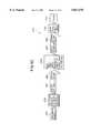
- FIG. 1is a diagrammatical top view of an automated immunoassay analyzer system
- FIG. 1Ais a diagrammatical top view of a portion of an automated immunoassay analyzer system
- FIG. 1Bis a cross sectional view of a portion of an automated immunoassay analyzer system taking along lines 1B--1B of FIG. 1A;
- FIG. 2is an exploded view of an incubation chamber
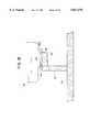
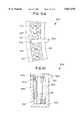
- FIG. 3is a cross sectional view of a preheat chamber region of an incubation chamber
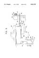
- FIG. 4is a cross sectional view of an incubation chamber
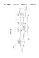
- FIG. 5is a side view of a split magnet assembly
- FIGS. 6 and 6Aare cross sectional views of an index mechanism
- FIG. 7is a cross sectional view of an elevator mechanism used in an incubation chamber
- FIGS. 8-8Bare a series of diagrams illustrating cycle timings in an incubation chamber
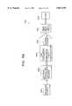
- FIGS. 9-9Care a series of flow diagrams illustrating exemplary protocols which may be run in the incubation chamber of the present invention.
- FIGS. 10 and 10Ashow an alternate embodiment of an incubation chamber having separately movable cuvette and magnet rings
- FIG. 11shows another alternate embodiment of an incubation chamber having separately movable cuvette and magnet rings
- FIG. 12shows yet another alternate embodiment of an incubation chamber having separately movable cuvette and magnet rings
- FIG. 13shows yet another alternate embodiment of an incubation chamber having separately movable cuvette and magnet rings.
- an automated immunoassay analyzer instrument 10includes an incubation chamber 12 having coupled thereto a luminometer 14 and photomultiplier tube 15, an index mechanism 16, a drive assembly 18, a cuvette feeder 20, a preheat chamber 22 and a plurality of probe stations 24a-24m generally denoted 24.
- a microprocessor based control system 25is coupled to and controls the operation of the automated analyzer instrument 10.
- the analyzer instrumentprocesses assays which are contained within the analyzer instrument in separate containers referred to as cuvettes.
- the microprocessor based control system 25includes a scheduler which determines a particular order in which to process assays. For example, the assays may be performed on a first-in-first-out (FIFO) basis. Alternatively, the scheduler may determine a particular order in which assays should be performed by using a Greedy algorithm, for example, to thus maximize throughput of the analyzer instrument 10.
- the analyzer instrument 10is thus provided as a random access immunoassay analyzer instrument capable of processing a plurality of different protocols and assays.
- the incubation chamber 12is provided from an insulative housing 26 portions of which have here been removed to reveal a chamber housing 28 over which the insulative housing 26 is disposed.
- the chamber housing 28includes temperature control means 40 FIG. (1A) to which is coupled a temperature control circuit 29 which sends control signals to the temperature control means 40 to thus control the temperature of the chamber housing 28.
- the incubation chamber 12also includes a magnet ring 30 and a cuvette ring 32 over which the chamber housing 28 is disposed.
- the cuvette ring 32is provided having a plurality of slots formed therein each of such slots adapted to accept a cuvette.
- the cuvette ring 32has 115 cuvette slots and can thus hold 115 cuvettes each of which may have an assay disposed therein.
- the system 10could alternatively be provided having cuvette and magnet rings sized such that the cuvette ring has greater or fewer than 115 cuvette slots.
- each of the 115 cuvette slots in the cuvette ring 32have been labeled with a numerical reference designation from 1 to 115. It should be noted that the numerical reference designation of the cuvette slots have been arbitrary assigned and are included here only to assist in explaining and understanding the operation of the incubation chamber 12.
- the cuvette ring 32is movably coupled to the magnet ring 30 such that the cuvette ring 32 can move relative to the magnet ring 30.
- the magnet ring 30has a magnet assembly 34 coupled thereto.
- the magnet assembly 34in this particular embodiment includes a pair of magnets 34a, 34b spaced by a predetermined distance here corresponding to a single cuvette slot.
- the cuvette feeder 20 and preheat chamber 22will be described in detail in conjunction with FIG. 3 below. Suffice it here to say, however, that cuvettes placed into the cuvette feeder 20 are fed into the preheat chamber 22 which leads to a cuvette entrance chute of the incubation chamber 12. Cuvettes are fed through the cuvette entrance chute and are disposed into the slots of the cuvette ring 32. The cuvette ring 32 thus holds the cuvettes as the cuvettes move around the incubation chamber 12.
- the assays in each of the cuvettesmay have different protocols. That is the assays may have different incubation times, different reagent addition times, different wash cycles, etc.
- a single pass assay cyclegenerally describes an assay having an incubation time period typically of about eight minutes and which passes by the magnets 34 and wash stations 24f, 24h, 24i only once.
- the incubation timecorresponds to the time between when a reagent is added to a cuvette until the time the cuvette reaches a first one of the magnets 34a, 34b in the magnet assembly 34.
- an eight minute incubation timeis achieved by adding a reagent to a cuvette which is positioned in the cuvette ring 32 such that the cuvette will not reach the magnet assembly 34 for about eight minutes.
- assaysmay require longer incubation times. For example some assays may require an incubation period typical of about eighteen minutes. Thus, as will also be described in conjunction with FIG. 9 below, to achieve an eighteen minute incubation period, a reagent is added to a cuvette positioned in the cuvette ring 32 which will not reach the magnet assembly 34 for a time period of about eighteen minutes.
- cuvettesmay make multiple revolutions around the incubation chamber 12 and thus pass by the magnets 34a, 34b and wash stations 24f, 24h, 24i two or more times.
- providing the incubation chamber 12 as a continuous track or loopavoids the necessity of having a plurality of different magnet assemblies, probe stations and wash stations thus reducing the need for extra parts and thereby reducing cost and increasing the reliability of the analyzer system 10. That is, by providing the incubation chamber 12 as a continuous track, cuvettes can be moved past processing stations multiple times thereby minimizing the number of protocol specific components included in the analyzer system 10.
- the incubation chamber 12is here shown having a circular or ring shape, in other embodiments it may be desirable for the incubation chamber 12 to be provided having a rectangular shape, a triangular shape, an oval shape or any other shape which allows the incubation chamber 12 to be provided as a continuous track.
- the particular shape of the incubation chamber 12may be selected in accordance with a variety of factors including but not limited to size, cost and space requirements of the incubation chamber 12 and analyzer system 10.
- cuvettesare placed in the hopper feeder 20 and are fed down a chute to the preheat chamber 22 where the cuvettes are heated to a temperature typically of about 37 degrees centigrade (° C).
- the preheat chamber 22is coupled to the temperature control circuit 29 which controls the temperature of the preheat chamber 22 independently of the temperature of the incubation chamber 12.
- the preheat chamber 22can be heated or cooled to any temperature independent of the temperature of the incubation chamber 12.
- the cuvettesare then moved through the preheat chamber 22 and fall through a cuvette entrance chute into one of the plurality of cuvette slots in the cuvette ring 32.
- the drive assembly 18is coupled to the magnet ring 30 of the incubation chamber 12 via a metal belt 35 having openings formed therein to accept corresponding studs or teeth projecting from an outer first surface of a drive pulley coupled to the drive assembly 18.
- the drive assembly 18can be provided as a bi-directional servo motor having the metal belt 35 coupled between the magnet ring 30 and the drive pulley of the bi-directional motor 18.
- the servo motorcould alternatively be provided as a stepper motor and the belt could be provided from a non-stretch material which is not metal.
- the belt 35is provided from steel to thus minimize belt stretching which would result in less accurate positioning of the magnet ring 30, and thus cuvettes, with respect to the probe stations 24.
- a first end of the belt 35can be fixed to the magnet ring 30.
- a friction couplingmay be provided between the belt 35 and the magnet ring 30.
- the cuvette or magnet ringmay be driven by a chain coupled between one of the rings and the motor 18. Suffice it to say that there are a plurality of means which can be used to couple the motor 18 to the rings 30, 32.
- the plurality of probe stations 24are disposed around the circumference of the incubation 12 at predetermined locations and are arranged to aspirate and/or dispense fluids from/to cuvettes at fixed positions around the circumference of the incubation chamber 12.
- the cuvette ring 32must rotate the cuvettes around the circumference of the incubation chamber 12 to position cuvettes at particular cuvette positions such that particular probe stations 24 can access the cuvettes to thereby allow particular operations to be accomplished at predetermined periods of time.
- a sample probe 24ais aligned at position 111 of the cuvette ring 32. Fluid samples which have been aspirated by the sample probe are dispensed into which ever cuvette is aligned with position number 111 of the cuvette ring 32.
- the cuvettein order to dispense a sample into a particular cuvette, the cuvette must be aligned under position number 111 of the cuvette ring 32.
- an ancillary probe 24bis aligned to dispense ancillary reagents into a cuvette which is aligned at position 115 of cuvette ring 32.
- a cuvette which requires an ancillary reagentmust be aligned at position 115 of the cuvette ring 32.
- a re-suspend probe 24cis aligned with position 4 of the cuvette ring 32 and thus a cuvette which requires a re-suspend fluid must be aligned at position 6 of the cuvette ring 32.
- an acid probe 24dis aligned to dispense acid into a cuvette which is aligned with position 6 of the cuvette ring 32 and thus a cuvette which requires an acid dispense must be aligned at position 6 of the cuvette ring 32.
- an aspirate probe 24eis arranged to aspirate fluid from a cuvette which is aligned with position 8 of the cuvette ring 32.
- a aspirate/wash probe station 24fis aligned to access cuvettes at position 9 of the cuvette ring 32.
- a re-suspend dispense probe 24gis arranged to dispense a fluid into a cuvette positioned between the magnets 34a, 34b at position number 9 of the cuvette ring 32 to thus re-suspend particles in the cuvette.
- a pair of wash and aspirate probes 24h, 24iare arranged to process cuvettes which aligned with positions 15 and 16 respectively of the cuvette ring 32.
- a plurality of reagent probe access stations 24j-24mare aligned to dispense reagents into cuvettes which are respectively aligned with positions 29, 31, 42, and 53 of the cuvette ring 32.
- the insulative and chamber housings 26, 28are provided having holes or spaces therein to allow the probes to access the cuvettes through the housings 26, 28. It should be noted that some of the probes 24i-24l may use the same holes in the housings 26, 28. However, such use cannot be simultaneous. It should also be noted that it may be possible in some embodiments to have a single probe perform more than one function. For example, a single probe may dispense reagents at either position 29 or position 31 of the cuvette ring 32.
- the magnet index assembly 16is aligned at position 23 of the cuvette ring 32. As will be described in detail in conjunction with FIG. 6 below, magnet index assembly 16 allows the cuvette ring 32 to move relative the magnet ring 30 and thus the magnets 34a, 34b.
- magnets 34a, 34bare here spaced by a single cuvette slot, in other embodiments it may be desirable to space the magnets 34a, 34b by a plurality of positions or alternatively to juxtapose the magnets 34a, 34b such that there is no gap between the magnets 34a, 34b.
- the spacing between the magnets 34a, 34bmay thus be selected in accordance with a variety of factors including but not limited to the particular type of assays being performed in the analyzer system 10.
- a plurality of temperature control means 40are coupled to the incubation chamber 12 to maintain the incubation chamber 12 at a predetermined temperature.
- four temperature control means 40are coupled to the incubation chamber 12. It should be noted, however, that fewer or more than four temperature control means 40 can be used.
- temperature control means 40should be selected such that the temperature of the incubation chamber 12 can be regulated and evenly maintained at a predetermined temperature. It should also be noted that each of the individual temperature control means 40 are coupled to the temperature control circuit 29 and that in some applications, it may be advantageous to set each of the means 40 at a different temperature.
- each of the temperature control means 40includes a mounting member 42 having a thermal electric device 44 (TED) mounted on opposite ends thereof.
- TEDthermal electric device 44
- FIG. 1BThe particular manner in which the TEDs 44 are mounted to the member 42 and coupled to the incubation chamber 12 will be described below in conjunction with FIG. 1B. Suffice it here to say that the TEDs 44 are coupled to the incubation chamber 12 and can either heat or cool the incubation chamber 12 to thus maintain the temperature of the incubation chamber 12 within a predetermined range of temperatures.
- the temperature control means 40is provided from eight TEDs 44 mounted in pairs on four TED mounting blocks 42 each of which are coupled to the mounting plate 52 by thermally conductive support member 50.
- the base ring 46 of the incubation chamber 12includes a step region 46a on which a thermal electric device (TED) 44 is disposed.
- An insulating member 48is disposed about the TED 44 to position the TED 44 with respect to the base ring step 46a and to thermally isolate the base ring 46 from the TED mounting member 42 and a support member 50.
- the TED mounting member 42 and the support member 50are each provided from a thermally conductive material such as aluminum, for example to thus provide a thermally conductive path between the TED 44 and a mounting plate 52.
- the insulating member 48is provided having an aperture therein with the shape of the aperture selected to substantially match the shape of the TED 44. For example, if the TED 44 is provided having a rectangular shape, then the insulating member 48 is provided having a rectangular shaped aperture provided therein. Thus, a first surface of the TED 44 contacts a bottom surface of the base ring 46 and a second surface of the TED 44 contacts the mounting member 50. The TED 44 is thereby coupled to the thermal path provided by the mounting member 50 and support member 50.
- the mounting plate 52supports the incubation chamber 12.
- the mounting plate 52is also provided from a thermally conductive material to thus absorb any thermal energy transmitted from the TEDs 44 through the TED mounting block 42 and through the thermally conductive support member 50.
- the incubation chamber 12includes a cover 60 here provided from a plurality of sub-cover sections 60a -60g which are disposed over a cuvette ring 62.
- the incubation chamber 12further includes a plurality of cuvette ring bearings 64a-64f generally denoted 64, a magnet ring 66, a magnet ring bearing 68 and a base ring 70.
- the cuvette ring 62is provided as a circular aluminum ring having 115 slots provided therein with each of the slots sized to accommodate a cuvette.
- the cuvette ring 62is movably coupled to the magnet ring 66 via the cuvette ring bearings 64a-64f.
- each of the cuvette ring bearings 64are provided having a substantially L shaped cross section.
- the bearings 64can be provided from plastic or any other material well known to those of ordinary skill in the art having sufficient strength to support the cuvette ring 62 while also allowing the cuvette ring 62 to rotate freely with respect to the magnet ring 66.
- a first or bottom surface of each of the cuvette ring bearings 64are disposed on a top surface of the magnet ring 66.
- the cuvette ring 62is disposed over the cuvette ring bearings 64 and a bottom surface of the cuvette ring 62 contacts a second or top surface of each of the cuvette ring bearings 64.
- the cuvette ring bearings 64act as friction type bearings which provide a region on which the cuvette ring 62 seats.
- the cuvette ring 62 and magnet ring 66are provided having an inside diameter typically of about 20 inches. It is thus relatively difficult to maintain tight tolerances during fabrication of the cuvette and magnet rings 62, 66.
- the cuvette ring bearings 64therefore are preferably positioned about the magnet ring 66 to accommodate for the inaccuracies, machining tolerances and other imperfections resultant from fabricating the cuvette and magnet rings 62, 66 to thus ensure that the cuvette ring 62 properly seats on the magnet ring 66. Also, and as will be described below, the cuvette ring bearings 64 insure the cuvette ring 62 moves freely relative the magnet ring 66.
- Each of the cuvette ring bearings 64are coupled to the magnet ring 66 via a pair of screws 65 and a set screw 124 which mate with threaded holes 67 and 71 respectively in the magnet ring 66.
- the set screws 65can be tightened to secure the cuvette ring bearings 64 in the axial direction.
- the set screwsprovide a means for adjusting the position of the cuvette ring bearings 64 while the cuvette ring bearings 64 provide a means for preventing the cuvette ring 62 from moving out of round and/or wobbling with respect to the magnet ring 66.
- the cuvette ring bearings 64thus allow the cuvette ring 62 to slide freely about the magnet ring 66 while still insuring that the cuvette ring 62 is firmly secured to the magnet ring 66.
- the cuvette ring 62is movably coupled to the magnet ring 66 via the cuvette ring bearings 64, it is recognized that any means for movably coupling the cuvette ring 62 to the magnet ring 66 may also be used. It should be appreciated that the cuvette ring 62 and magnet ring 66 in fact need not be physically coupled together as long as the two rings can be accurately moved and positioned relative to each other.
- the magnet ring bearing 68is first disposed over the base ring 70 and located in a particular position with respect to the base ring 70 via an alternating sequence of locating pins 72 and screw holes 74 which here are equally spaced around the perimeter of the base ring 70.
- the ring bearing 68is provided having corresponding through holes 76 disposed to accept the locking pins 72 and allow the ring bearing 68 to be fastened to the base ring 70 via screws or other fastening means (not shown).
- the magnet ring 66is then press fit onto the ring bearing 68. To insure an accurate press fit, the magnet ring 66 and ring bearing 68 are manufactured having a filed interference fit. It should be noted that in alternate embodiments, the magnet ring 66 and ring bearing 68 could, of course, be provided as a single piece in which case the magnet ring 66 would form the outer race of the assembly.
- the cuvette ring 62 and the cuvette ring bearing 64are then coupled to the assembly formed by the magnet ring 66, magnet ring bearing 68 and base ring 70.
- the chamber covers 60are then disposed over the entire ring assembly 90 to form the incubation chamber 12.
- the cover 60is provided from a plurality of sub-covers 60a-60g.
- Sub-cover 60acorresponds to a back area cover
- sub-cover 60bcorresponds to a servo area cover
- sub-cover 60ccorresponds to a sample area cover
- sub-cover 60dcorresponds to a wash area cover
- sub-cover 60ecorresponds to an index area cover
- sub-cover 60fcorresponds to a reagent probe area cover
- sub-cover 60gcorresponds to a luminometer area cover.
- each of the chamber covers 60a-60gare selected to be equal to thus reduce the manufacturing costs and complexity of the chamber covers 60.
- the sample area cover 60cis provided having a pair of slots 61a, 61b in a bottom surface thereof.
- the slots 61a, 61ballow the belt 35 (FIG. 1) and sensors (not shown) to be disposed in the incubation chamber.
- the sample area cover 60calso has a hole 61c provided in a top surface thereof.
- the hole 61callows a sample probe to access a cuvette in the cuvette ring 62.
- each of the sub-coversmay be provided having slots and holes therein to thus accommodate probes, sensors or any other devices which require access to the inside of the incubation chamber.
- the wash separation cover 60dincludes a pair of windows 82 through which a user operator can view the paramagnetic particle separation step of any particular assay cycle.
- each of the covers 60a-60gare preferably provided from a thermally conductive material such as aluminum to thus provide good thermal transfer characteristics with the base ring 70.
- the covers 60a-60gcould be provided from plastic.
- One problem with the plastic cover approachis that the incubation chamber 12 may have resultant warm regions and cold regions due to the poor thermal conduction characteristics of plastic. It is not desirable when processing the assays to subject the assays to arbitrarily varying temperature zones within the incubation chamber 12. Thus in the event it was desirable to provide the sub-covers 60a-60g from a material which is a poor thermal conductor, such as plastic for example, a thermally conductive finish could be disposed over the material to thus provide the incubation chamber 12 having relatively even thermal characteristics.
- an insulation cover(FIG. 6) is disposed over the entire assembly.
- the insulation covermay be provided, for example, as a one piece-vacuum form cover to thus reduce cost and facilitate assembly.
- the preheat chamber 22includes a preheat chamber entrance chute 82 through which cuvettes 84 are disposed into an entrance position of a first channel region 88 of the preheat chamber 22.
- Cuvettes 84are disposed in the entrance chute 82 and rest upon a first surface of a pusher block 90 here shown in a fully extended position.
- the pusher block 90is coupled through a follower block 92 and lead screw 94 to a drive system 96 which may be provided from a stepper motor for example.
- the first end of the lead screw 94has a lead screw pulley 98 coupled thereto.
- the drive system 96includes a shaft 100 having a drive-shaft pulley 102 coupled thereto.
- a belt 104is coupled between the lead screw pulley 98 and the drive-shaft pulley 102.
- the drive system 96turns the lead screw 94 in first and second opposite directions to thereby move the follower block 92 in first and second opposite directions along the length of the lead screw 94 and thus move the pusher block 90 in first and second opposite directions along the length of the preheat channel.
- the follower block 92has a pair of tabs 105 extending from a bottom surface thereof.
- the tabs 105interact with a pair of optical sensors 106a, 106b which sense the position of the pusher block 90 and feed positioned information to the control system 25 (FIG. 1).
- a cuvette 84falls through the opening and into the channel 28 of the preheat chamber 22.
- the pusher block 90pushes the cuvette 84 from the entrance position directly under the entrance chute 82 along the channel region 88 until the cuvette reaches an incubation chamber 12 entrance chute 114.
- the incubation chamber 12is here shown to include the cover 50, the base ring 70 and the magnet ring bearing 68 which are coupled to form a closed channel in which the cuvette 84 is disposed.
- the cuvette ring 62 (FIG. 2) and magnet ring 66 (FIG. 2)have been omitted for clarity.
- Disposed around the cover base ring and magnet ring bearing 68 of the incubation chamber 12are a pair of insulating members 108, 110.
- the insulating members 108, 110are here provided from a closed cell foam material having a thickness typically of about 0.25 inches. Other materials having similar insulation characteristics may of course also be used.
- the incubation chamber cover 28 and base ring 70are provided from aluminum.
- An end cap 112forms the cuvette entrance chute 114 from the preheat chamber channel region 28 into the incubation chamber 12.
- the cuvette 84travels through the cuvette entrance chute 114 through an aperture 117 of the incubation chamber 12 and seats in a slot of the cuvette ring 62 (FIG. 2).
- the cuvette slotsshould be provided having a shape selected to accommodate the shape of the cuvette 84 such that the cuvette 84 can easily be accepted therein without having any surfaces that tend to bind or catch on a surface of the cuvette 84.
- the cuvette slotshould be provided having a shape which positions the cuvette 84 and holds the cuvette 84 relatively securely in the cuvette ring 62.
- the shape of the cuvette slotshould also be selected such that cuvettes 84 can fall freely from the entrance chute 114 into the cuvette slot in a self guiding manner.
- the cuvette slotshould be provided having a shape that could be manufactured relatively inexpensively.
- the preheat channel 88has disposed thereover an acrylic cover 116 having a thickness typically about 0.25 inches which provides the preheat chamber 22 as a closed channel and also serves to insulate the preheat chamber 22 from other surfaces contacting the top portion of the preheat chamber 22.
- the entrance from, the preheat chamber 22 to the incubation chamber 12is spaced a relatively short distance from the luminometer 14 and in particular from the luminometer entrance chute 114.
- the cuvette entrance from the preheat chamber 22 to the incubation chamber 12could be disposed at any region of the incubation chamber 12.
- the luminometer 14provides a means for removing cuvettes 84 from the incubation chamber 12 and from the analyzer system 10. That is, a cuvette 84 can be moved from the cuvette ring 62 into the luminometer 14. The luminometer 14 measures the amount of light emitted from a chemiluminescent reaction which takes place in the cuvette 84. Upon completion of the measurement, the luminometer 14 expels the cuvette 84 in which the reaction took place from the analyzer system 10 (FIG. 1).
- the magnet ring and cuvette ringcan move in both clockwise and counter clockwise directions there is a great deal of flexibility with respect to the particular placement of devices such as the probes 24, the luminometer 14, the index mechanism 16 and the cuvette entrance chute 22 about the incubation chamber.
- the devicesmust be placed to allow certain processes to take place at predetermined periods of time and thus must be selected in accordance with the motions of the cuvette and magnet rings. Exemplary motions of the cuvette and magnet rings will be described in conjunction with FIGS. 8-8b below.
- the incubation chamber 12includes the cover 60 and base 70 here coupled together via screws 120a, 120b. It should be noted, however, that any type of fastening technique well known to those of ordinary skill in the art may also be used to secure together the cover 60 and base ring 70 portions of the incubation chamber 12.
- a cuvette 84is shown disposed in a cuvette slot 122 of the cuvette ring 62.
- the cuvette 84is provided having a top flange 84a, which rests on shoulder region 62b of the cuvette ring 62 and a side flange 84b which engages side wall regions of the cuvette ring 62 which form the cuvette slot 122.
- a first surface of a cuvette ring 62is disposed against a first surface of a cuvette ring bearing 64.
- a second surface of the cuvette ring bearing 64is disposed against a first surface of the magnet ring 66.
- the cuvette ring bearing 64is held in place by a pair of screws and an adjustable set screw 124. The cuvette ring bearing 64 thus secures the cuvette ring 62 in a predetermined axial position relative the magnet ring 66.
- the magnet ring 66is coupled via a press fit to an outer race of the magnet ring bearing 68.
- the magnet ring bearing 68also includes an inner race spaced from and movably coupled to the inner race by a ball bearing 69.
- the ball bearing 69allows the outer race to move relative the inner race as is generally known.
- a screw 126 and washeralso secures a first end of the metal drive belt 35 to the magnet ring 66.
- a second end of the drive belt 35is similarly fixed to the magnet ring 66.
- first and second ends of the drive belt 35are pinned to the magnet ring 66 at predetermined locations.
- a member 128projects from the magnet ring 66 in the region where the belt 35 terminates with respect to the ring 66.
- the member 128has projecting therefrom a fin 128a having a radial shape which interrupts a sensor such as an optical sensor when the magnet ring 66 has moved as far as possible in one direction.
- the servo motor 18drives the magnet ring 66 slowly in one direction until the fin 128a interrupts the optical sensor thus indicating that the belt cannot allow the magnet ring to turn any further in that direction.
- This techniqueis used to initialize an encoder coupled to the servo motor 18 and allows the encoder to determine start and end positions of the magnet ring 66.
- the sensor flag and optical sensor arrangementcan act as a fail safe mechanism. If the servo motor attempts to drive the magnet ring past a predetermined point in a single direction, the sensor sends a signal to initiate shut down of the servo motor and thus prevents the magnet ring or the drive belt from being broken. Furthermore, a physical stop may be disposed to engage the member 128 and prevent the magnet ring from advancing too far in one direction in the event that both the encoder and optical sensor fail to operate properly.
- the magnet ring 66thus turns in response to movements of the drive belt 35. Since the drive belt 35 is pinned to the magnet ring 66, it is not possible for the magnet ring 66 to rotate in a single direction for a distance greater than 360 mechanical degrees. That is, in this particular embodiment, the magnet ring 66 cannot continuously spin in any one direction.
- the metal drive belt 35is pinned to the magnet ring 66.
- the magnet ringcould be provided having teeth similar to the drive pulley which engages holes in the metal belt.
- the drive unit 18is provided as a servo motor capable of very accurately turning the drive belt 35 and thus the magnet ring 66.
- the incubation chamber 12further includes a magnet pair 130 provided from magnets 130a, 130b coupled to the magnet ring 66 via a mounting plate 132.
- the magnet pair 130 and mounting plate 132will be described in detail below in conjunction with FIG. 5. Suffice it here to say that as described above in conjunction with FIG. 1, as the cuvette 84 passes by the magnets 130a, 130b the magnets attract and hold paramagnetic particles disposed in the cuvette 84 to a first surface of the cuvette 84b proximate the magnets 130a, 130b. In this manner the paramagnetic particle separation portion of the assay is achieved.
- a split magnet assembly 140includes the magnet pair 130a, 130b, generally denoted 130 separated by a spacer 142 a predetermined distance from a second pair of magnets 144a, 144b, generally denoted 144.
- the magnet pairs 130, 144are offset in a vertical direction by a predetermined distance D1 to facilitate the paramagnetic particle separation procedure.
- the magnet pairs 130, 144are secured to a magnet mounting plate 132 which in turn is secured to the magnet ring 66.
- the magnet pairs 130, 144are secured to the mounting plate 132 by providing the mounting plate 132 from a magnetically attractive material such as steel and allowing a magnetic force to hold the magnet pairs 130, 144 to the mounting plate 132.
- the magnet pairs 130, 144may be secured to the mounting plate 132 via an epoxy or by any other fastening technique well known to those of ordinary skill in the art.
- the magnet plate 106need not be provided from a magnetically attractive material.
- a pair of bolts 146secure the mounting plate 132 to the magnet ring 66.
- the mounting plate 132may be attached to the magnet ring 66 using epoxy or any other fastening technique well known to those of ordinary skill in the art. In some embodiments, however, it may be preferable to omit the mounting plate 132 and mount the magnet pairs 130, 144 directly to the magnet ring 66.
- the magnet pairs 130, 144are here selected having equal lengths. Each of the magnet pairs 130, 144 spans a distance covering six cuvette slots in the cuvette ring 62. Thus, six cuvettes 84 can be positioned in front of each of the magnet pairs 130, 144 at any time.
- By spacing the magnet pairs 130, 144 and performing a particle re-suspension operation in a cuvette 84 positioned in the space between the magnetsit is possible to improve the results of some assays and in particular it is possible to improve the results of some ID assays. It should be noted that the magnet pairs 130, 144 could of course be provided having a longer or a shorter length and that in some applications the magnet pairs 130, 144 could be provided having different lengths.
- each of the magnet pairs 130, 144is selected based, inter alia, on the amount of time it is desired to expose an assay to a magnetic force. Thus assuming that it is desired to expose an assay to a magnetic force for a predetermined period of time, if the cuvettes 84 are moved past the magnet pairs 130, 144 at a first predetermined speed, the magnet pairs 130, 144 should be provided having a first length.
- the magnet pairs 130, 144should be made shorter such that the assays are positioned in front of the magnets for a shorter distance but for the same predetermined period of time.
- the particular length of the magnet pairs 130, 144should be selected in accordance with a variety of factors including but not limited to the speed with which cuvettes 84 pass by the magnets and the amount of time required to ensure proper paramagnetic particle separation in the cuvette 84.
- a first end of a first one of the magnet pairs 130, 144is spaced by a distance typically about the length of a single cuvette from a first end of second one of the magnet pairs 130, 144.
- a single cuvette 84can be positioned in front of the spacer region and thus not be subject to the magnetic forces of the magnets. It is recognized, of course, that in some applications it may be desirable to space the magnet pairs 130, 144 by a distance which is greater than one cuvette. Alternatively, it may be desirable in some applications to not space the magnets at all but rather to couple the magnets adjacent to each other on the mounting plate 132.
- the magnets 130a, 130b, 144a, 144bare preferably provided having a shape corresponding to the shape of the surface of the magnet ring 66 to which the magnets are coupled.
- the magnet ring 66is provided having a circular shape.
- the magnetsare provided having a curvature corresponding to the curvature of the magnet ring 66.
- the paramagnetic particlesare gathered from both the upper and lower portions of the cuvette and are eventually focused into a pellet along the center of the lower magnet pair 144.
- a wash operationis then performed to remove non-bonded particles within the cuvette 84.
- the cuvette 84moves past the magnet pair 144 paramagnetic particles are further focused into a pellet along the center line of the lower magnet pair 144.
- a focused pelletis formed from particles gathered across the entire cuvette 84.
- the distance between the lowest edge 145 of magnet pair 144 and the highest edge 131 of the magnet pair 130is, in this embodiment, selected to be less than the length of the fill volume of the cuvette 84.
- an index mechanism 150includes an index housing 152 coupled to the incubation chamber 12 cover via several bolts 154 one of which is shown here.
- An index plunger 156disposed through a bore in the index housing 152 and is located in the housing bore by a guide bearing 158.
- a first end 156a of the index plunger 156is coupled to a lead screw 160.
- the lead screw 160is coupled to a linear drive motor 162 which is here provided as a stepper motor.
- the guide bearing 158allows the index plunger 156 to move up and down through the bore in the index housing 152 in response to movements of the motor 162 and drive shaft 160.
- a clamp foot 164is disposed about a second end of the plunger 156.
- the clamp foot 164may be provided, for example, from a piece of rubber tubing having a predetermined durometer hardness.
- a bore 174 of the magnet ring 66has disposed therein a detent spring 166 and a first end of a stainless steel detent pin 168.
- a guide bushing 170is disposed in the slot to prevent the detent pin 168 from wearing down the magnet ring walls.
- the guide bushing 170may be provided, for example, as an oil impregnated bronze bushing. As the bushing walls wear down, the bushing 170 leaches out lubricant and thus the bushing 170 acts as a self lubricating bushing.
- Those of ordinary skill in the artwill appreciate of course that other wear resistant materials and techniques for reducing or minimizing wear between two moving surfaces could also be used.
- a retainer pin 172is disposed through a slot in the detent pin 168. A first end of the retainer pin 172 is coupled to a first wall 66a of the magnet ring 66. A second end of the retainer pin 172 is disposed through a hole in a second wall of the magnet ring 66 and coupled to a retainer block 178.
- the detent pin 168when the index plunger 156 is in its up position as shown in FIG. 6A , the detent pin 168 is placed in its detent position. In its detent position, the first end 168a of the detent pin 168 remains coupled to the magnet ring 66 as described above.
- the detent spring 166forces a second end 168b of the detent pin 168 through a slot formed in wall region 180 in the cuvette ring 62.
- the detent pin 168engages the cuvette ring 62 and locks the cuvette ring 62 to the magnet ring 66 thereby preventing the cuvette ring 62 from moving relative to the magnet ring 66.
- the cuvette ring 62moves with the magnet ring 66. Additionally, when the cuvette ring 62 is locked to the magnet ring 66 via the detent pin 168, the position of the magnet pairs 130, 144 (FIG. 5) is fixed with respect to cuvettes 84 held in the cuvette ring 62.
- the detent pin 168is shown disengaged from the cuvette ring 62 thereby unlocking the cuvette ring 62 from the magnet ring 66.
- the cuvette ring 62is movably uncoupled from the magnet ring 66. That is, the cuvette ring 62 can move on the cuvette ring bearings 64 (FIG. 4) relative to the magnet ring 66
- the detent pin 168is disengaged from the cuvette ring 62 in the following manner.
- a first surface 156b of the second end of the index plunger 156contacts a first surface of the detent pin 168 and drives the detent pin 168 against the detent spring 166 until the detent pin 168 is pushed completely through the slot in the cuvette ring 62.
- the cuvette ring 62is de-coupled from the magnet ring 66 and can therefore move relative to the magnet ring 66.
- the slot in the detent pin, through which the retainer pin 172 is disposed,is provided having a length selected to allow the detent pin 168 to be pushed down against the detent spring 166 a distance sufficient to allow the detent pin 168 to pushed through the detent slot in the wall region of the cuvette ring and below the surface of the cuvette ring 62 before the retainer pin 172 bottoms against a surface of the detent pin 168 in the slot region 174 of the detent pin 168.
- the retainer pin 172Since the retainer pin 172 has a force exerted on it each time the magnet ring 66 indexes with respect to the cuvette ring 62, it is desirable to ensure that the retainer pin 172 is firmly secured to the magnet ring 66. In this particular embodiment, the walls of the magnet ring 66 through which the retainer pin 172 is disposed are not thick enough to properly support the retainer pin 172. Thus, the retainer block 178 is coupled to the magnet ring 66 to add support to the retainer pin 172. The retainer block 178 can be fixed to the magnet ring 66 by screws, epoxy, or by any other fastening techniques well known to those of ordinary skill in the art.
- the cuvette ring 62has a plurality of like detent slots formed therein.
- the detent pin 168can engage each of the like detent slots in the cuvette ring 62.
- Each detent slot in the cuvette ring 62defines a relative position between the cuvette slots in the cuvette ring 62 and the magnet pairs 130, 144 coupled to the magnet ring 66.
- the detent pin 168slides off the surface 156b of the index plunger 156 and moves along a bottom surface of the cuvette ring 62 until the detent pin 168 is aligned under the next detent slot in the cuvette ring 62.
- the detent spring 166forces the detent pin 168 through the detent slot to again couple the cuvette ring 62 to the magnet ring 66.
- the detent pin 168is forced by the spring 166 into the next available detent slot of the cuvette ring 62 to thus re-secure the cuvette ring 62 to the magnet ring 66.
- the detent pin 168 and the slots in the wall 180 of the cuvette ring 62constitute an escapement and the plunger 156 of the index mechanism 150 constitutes a trigger for the escapement.
- the detent pin 168 and detent spring 166exert a force on the bottom surface of the cuvette ring 62.
- the clamp foot 164provides a force against a top surface of the cuvette ring 62 to counteract the force exerted by the detent pin 168 and detent spring 166. Additionally, the clamp foot tubing reduces flexing and dampens any oscillation of the cuvette ring 62 which occurs due to the index pin being forced into the detent slot of the cuvette ring 62.
- detent pin 168locks the cuvette ring 62 to the magnet ring 66
- other locking meansmay also be used.
- an index plunger 156is used to disengage the cuvette ring 62 from the magnet ring 66
- other disengaging meansmay also be used.
- the detent pin 168 and index plunger 156 arrangementcould be replaced by a solenoid for example.
- the cuvette ring 62 and the magnet ring 66may each include engageable locking regions which interact to thereby selectively lock the cuvette ring 62 and magnet ring 66. It should, however, be noted that in some embodiments the cuvette ring 62 and magnet ring 66 may not include locking regions but rather may simply move independently of each other to thus move the magnets pass the cuvettes.
- the rubber tube clamp foot 164contacts the cuvette ring 62 to provide a downward force to counteract the upward force provided from the spring and detent pin 168 and spring and thereby minimize movement of the cuvette ring 62 in a vertical direction.
- the rubber tube clamp foot 164could be replaced by a foot spring and clamp foot arrangement for example.
- the foot springshould be selected having a spring force to dampen and counteract the forces which arise when the detent pin 168 is pushed by the spring against the cuvette ring 62.
- a shoulder region of the index plunger 156compresses the foot spring against the clamp foot to thus counteract the force which the detent pin 168 exerts on the cuvette ring 62 surface due to the upward force provided by spring 166.
- Those of ordinary skill in the artwill now appreciate that other means for dampening and counteracting the forces which arise while indexing the cuvette ring 62 relative to the magnet ring 66 can also be used.
- the index plunger 156 and detent slot in the cuvette ring 62are provided having tolerances to ensure that in a worst case tolerance scenario (i.e. the index plunger 156 having a maximum diameter and the index slot having a minimum diameter) the index plunger 156 will not be provided having a diameter greater than the diameter of the detent slot.
- the nominal clearance between the second end of the index plunger 156 and the index slotis typically about 0.003 inches. Such a relatively tight clearance prevents the cuvette ring 62 from shifting position while the index operation is taking place. It is desirable to prevent any cuvette ring 62 movement from occurring during the index operation since other operations may simultaneously be taking place. For example, sample, reagent or wash probes may be entering cuvettes 84 during the index operation.
- the drive system 18must position the cuvette ring 62 within several one-thousandths of an inch in order to ensure that the second end of the plunger can move through the detent slot.
- the drive system 18moves the cuvette ring 62 a predetermined number of positions in a predetermined time interval, for example, 53 positions in one second, the drive system 18 must be capable of stopping and positioning the cuvette ring 62 within several-thousandths of an inch of a predetermined position.
- the second end of the index plunger 156can be provided having a tapered region to allow the index plunger 156 to accommodate some cuvette ring 62 misalignment which may occur.
- the drive system 18includes a servo motor capable of accurately moving a predetermined distance.
- the drive system 18also includes the metal drive belt 35 having a plurality of accurately spaced and sized holes provided therein. Moreover, teeth projecting from a drive pulley of the motor 18 which engage the holes in the metal drive belt 35 are positioned very accurately on the drive pulley to thus increase the accuracy with which the drive system 18 can position the magnet ring 66 and thus the 5 cuvette ring 62.
- metal belt arrangement, backlash in the drive system 18i.e. the amount of play the drive belt 35 has as it engages a tooth on the drive motor pulley
- backlash in the drive system 18is typically about 0.002 inches.
- the base ring 70 and magnet ring bearing 68are each provided having bores therein.
- An alignment pinhaving a first end disposed in the bore of the base ring 70 and having a second end disposed in the bore of the magnet ring bearing 68 provides a means for properly aligning the base ring 70 and the magnet ring bearing 68.
- FIGS. 6 and 6Agaps or spaces are shown between the base ring 70, the magnet ring bearing 68 and the magnet ring 66, such gaps are shown only to facilitate understanding of the assembly.
- Each of the above mentioned assembliesin fact, are tightly fit to each other to thus prevent movement between each of the pieces.
- the magnet ring bearing 68provides a thermal path through which heat generated by the thermal means coupled to the base ring 70 may be transferred throughout the incubation chamber 12.
- an elevator assembly 190includes a lift rod 192 and a drive assembly 194.
- the drive assembly 194drives the lift rod 192 through a predetermined region of the incubation chamber 12 to thus lift a cuvette 84 through an entrance shaft 196 of the luminometer 14 only a portion of which is here shown.
- the elevator assembly 190positions the cuvette 84 into a predetermined one of a plurality of cuvette chambers within the luminometer 14. In this manner, cuvettes 84 are removed from the incubation chamber 12 thus opening up a cuvette slot in the cuvette ring 62 to thus allow a new cuvette 84 to be placed into the cuvette ring 62.
- the cuvette 84may simply be ejected from the incubation chamber 12 at any convenient location and passed to a second different incubation chamber 12 or alternatively the cuvette 84 may be ejected and disposed of in any manner appropriate to the system in which the incubation chamber 12 is being employed.
- the elevator assembly 190includes a pair of sensors 200a, 200b which sense the position of the lift rod 192 and thereby determine the position of the cuvette 84 in the elevator shaft.
- the sensors 200a, 200bsend signals to the control system 25 (FIG. 1) to prevent the control system from turning the cuvette and magnet rings 62, 66 while the lift rod 192 is disposed through the incubation chamber 12. Once the elevator lift rod 192 retracts out of the incubation chamber 12, the sensor assemblies send a signal to the control system 25 which then allows the magnet and cuvette rings 62, 66 to begin moving again.
- FIGS. 8-8Ba series of diagrams illustrating the movements of the cuvette ring 62 and magnet ring 66 during three different system cycles is shown. It should be noted that these cycles are merely illustrative of the plurality of possible cycles which can be implemented in the system 10 and are not to be considered limiting with respect to the types of cycles which can be performed in the system 10.
- FIG. 8a diagram illustrating the movements of the cuvette and magnet rings 62, 66 during a typical cuvette cycle 210 of the system 10 is shown.
- the cuvette cycle 210is defined to have a 15 second time interval. It should be noted, however, that other cuvette cycle times can also be defined.
- the 15 second cuvette cycleis shown divided into 3 portions time frames 212, 214, 216. During each portion of the cuvette cycle, the cuvette ring 62 and magnet ring 66 are able to move in either clockwise or counter clockwise directions.
- the frame 212 of the cuvette cycle 210lasts for a period of time corresponding to about 5 seconds.
- the cuvette ring 62moves 53 positions in a counter clockwise direction around the incubation chamber 12.
- the cuvette ring 62does not move and one or more of the following operations can be performed.
- primary reagentscan be added to particular cuvettes.
- the particular type of assay being processedwill determine the particular primary reagent which should be added as well as the incubation time of the assay. Some assays have incubation times typically of about eight minutes while other assays may have incubation times of about eighteen minutes.
- ancillary reagentse.g. pretreatment or release reagents used to prepare or dilute a sample for a particular test can also be added to particular cuvettes during this portion of the cycle.
- any cuvettesare appropriately positioned in the wash/paramagnetic particle-separation region of the incubation chamber 12 (i.e. cuvette ring positions 8-20 as shown in FIG. 1) wash and re-suspension operations may take place during this portion of the cycle. Also if an appropriate cuvette is positioned at cuvette ring position number 6, an acid dispense into the cuvette may also take place. Thus suffice it to say that a plurality of different operations may take place at different process stations of the incubation chamber 12 during frame 212 of the cycle 210.
- the movements of the cuvette which occur during the second frame 214 of the cycledepend upon the particular test being performed. For example, if an assay having an incubation period lasting for about 8 minutes is being dispensed then the cuvette ring 62 moves in a clockwise direction 39 positions such that a particular cuvette is positioned under the sample dispense probe. The 39 position move is accomplished in 0.8 seconds.
- a new sampleis dispensed from the sample dispense probe into the cuvette or a diluted sample previously aspirated may be dispensed into a new cuvette.
- the dispensemust take place in a period of time typically about 2.5 seconds.
- the cuvette ring 62then moves clockwise 5 additional cuvette positions to position the cuvette under the ancillary dispense position.
- the 5 position movementis accomplished in 0.2 seconds.
- the second frame 214 of the cycle 210is completed in about 3.5 seconds and the total number of positions moved during that total time corresponds to 44 all in a clockwise direction around the incubation chamber 12.
- ancillary reagentscan be added to appropriate cuvettes and cuvettes are added and exited from the incubation chamber 12. This occurs in a time period of about 3.1 seconds.
- the cuvette ring 62moves in a clockwise direction 8 positions such that the detent pin 168 is aligned under the index mechanism 150.
- the index mechanism 150disengages the cuvette ring 62 from the magnet ring 66 as described above in conjunction with FIGS. 6 and 6A and the magnet ring 66 is moved relative the cuvette ring 62.
- the detent pin 168then re-engages the cuvette ring 62 to the magnet ring 66. It should be noted that during the index step the cuvette ring 62 is stationary and the magnet ring 66 moves 1 position in a clockwise direction. In alternate embodiments however, it may be desirable to move the cuvette ring 62 rather than the magnet ring 66.
- the total cuvette cyclelasts for a time period of about 15 seconds and in this particular example the cuvette ring 62 has moved a total of 105 positions (53 positions in a counter clockwise direction and 52 positions in a clockwise direction) and has advanced a cuvette around the incubation chamber 12 one cuvette slot. In this embodiment, the cuvette advances toward the magnet in the counter clockwise direction.
- a cuvettedoes not remain in a stationary position for more than 5 seconds even though the total cycle time is 15 seconds. That is, each cuvette is advanced a single position around the incubation chamber 12 and a single position relative to the magnet 130, 144 every 15 seconds. However, no one cuvette remains under a single position of a probe station 24 (FIG. 1) for longer than 5 seconds within the 15 second cuvette cycle time.
- FIG. 8Aa diagram illustrating the movements of the cuvette and magnet rings 62, 66 during a second different cycle 220 is shown.
- the cycle 220is divided into three frames as was cycle 210 described above in conjunction with FIG. 8. The same operations performed in the first and last frames 212, 216 of cycle 210 can be performed in the first and last frames 212, 216 of cycle 220.
- the cuvette ringmoves in a clockwise direction 4 cuvette positions in 0.2 seconds. Then a diluted sample may be dispensed into a clean cuvette. This operation must be completed in about 2.5 seconds.
- the cuvette ringthen moves 40 positions in a clockwise direction in a time period of about 1 second and stops in the ancillary reagent dispense position.
- the cuvette ringmoves a total of 105 positions in about 15 seconds and has advanced a cuvette around the incubation 12 one cuvette slot relative to the magnet pairs 130, 144 disposed on the magnet ring 66.
- FIG. 8Ba diagram illustrating the movements of the cuvette and magnet rings 62, 66 during a third different system cycle 224 is shown.
- the total cycle 224is again divided into three time frames 212, 226 and 216.
- the same operations performed in frames 212, 216 described above in conjunction with FIGS. 8 and 8Acan be performed in frames 212, 216 of cycle 224.
- the system 10performs different operations than those performed in the frame 214 of cycles 210 and frame 222 of frame 220.
- the cuvette ringmoves five positions in a counterclockwise direction in about 0.25 seconds.
- the cuvette ringremains stationary for about 2.5 seconds during which time a diluted sample may be dispensed into a new cuvette at the sample position.
- a new samplemay be disposed into a cuvette.
- the cuvette ringthen moves 49 positions in a clockwise direction and stops in the ancillary reagent dispense position.
- the cuvette ringhas moved a total of 115 cuvette ring positions and has advanced a cuvette around the incubation chamber 12 toward the magnet pairs 130, 144 by a distance corresponding to one cuvette slot.
- FIGS. 9-9Ca series of process steps illustrating a plurality of different protocols which can be accommodated in the analyzer system 10 (FIG. 1) are shown. It should be noted that these protocols represent only a small number of a vast plurality of protocols which can be accommodated by the analyzer system 10, and that the protocols here shown are only intended to be representative and illustrative of the types of protocols and protocol steps which can be accommodated in the analyzer system 10 and should not be construed as limiting as to the types of protocols which can be accommodated in the system 10.
- the one step protocolrefers to a protocol in which only one wash step is performed.
- a predetermined amount of a sampleis added to a cuvette positioned at the sample probe station in slot 122 of the cuvette ring 62.
- the precise amount of the sample which is added to the cuvetteis selected in accordance with the type of assay being performed but in this particular protocol the sample amount is within the range of about five microliters (ul) to two-hundred ul of sample fluid.
- solid phase and light reagentscan be added to the cuvette. Again, the precise amount of either reagent which is added is selected in accordance with the type of assay being performed. In this particular protocol between 100 and 450 ul of a solid phase reagent and between 50-250 ul of a light reagent are added to the cuvette.
- the incubation periodis defined as the period of time between when a first primary reagent is added to the sample fluid in the cuvette and when the cuvette reaches the magnet pair 130 (FIG. 5).
- the incubation periodcan last for a time period typically of about eight minutes or alternatively the incubation period can last for a time period typically of about eighteen minutes.
- the eighteen minute incubation periodis achieved by adding the reagent to the cuvette such that the cuvette remains in the incubation chamber 12 for about eighteen minutes before the cuvette reaches the magnets.
- the first reagentshould be dispensed into a cuvette which is held in position 92 of the cuvette ring.
- the reagentis dispensed by a reagent probe which can only access cuvettes in position 29 of the cuvette ring.
- the cuvette ringmoves the cuvette in position 92 to position 29 for dispensing by the reagent probe.
- the first magnetis disposed at position 20 of the cuvette ring which is 72 positions away from position 92. Thus the cuvette and magnets are spaced by a distance of 72 cuvettes positions.
- the reagentis dispensed by probe 241 into a cuvette at position 53 of the cuvette ring 62.
- the first magnetis location at position 20 on the cuvette ring 62.
- the ancillary reagentis dispensed from the ancillary reagent probe 24b at position 115.
- Ancillary reagentsare dispensed into cuvettes at position 71 of the cuvette ring.
- the cuvette ringmust move a cuvette at position 71 of the cuvette ring to position 115 of the cuvette ring to allow an ancillary reagent to be dispensed therein.
- a first reagentis dispensed from reagent probe 241 at position 53 which is 18 cuvette positions away from the ancillary reagent probe.
- the ancillary incubation timeis 4.5 minutes (18 ⁇ 15/60). It should be noted, however, that the ancillary incubation time in an assay having an eighteen minute incubation time will be longer than 4.5 minutes.
- a wash cycleis performed following which the cuvette is passed to the luminometer 14 and as shown in process step 240 a chemiluminescent reaction and resultant light flash is measured via the luminometer 14.
- the one step with dilutions protocolrefers to a protocol in which a diluent is added to a cuvette and only one wash step is performed. Sometimes referred to as "Forward Sandwich” assays.
- a predetermined amount of a sampleis added to a cuvette positioned at the sample probe station in slot 111 of the cuvette ring 62.
- the precise amount of the sample which is added to the cuvetteis selected in accordance with the type of assay being performed but in this particular protocol the sample amount is within the range of about five microliters (ul) to two-hundred ul of sample fluid.
- a diluentis added to the sample to thus dilute the sample.
- the samplemay be diluted by one-half for example or by one thousand times or by any other amount depending upon the assay requirements.
- solid phase and light reagentscan be added to the cuvette. Again, the precise amount of either reagent which is added is selected in accordance with the type of assay being performed. In this particular protocol between 100 and 450 ul of a solid phase reagent and between 50-250 ul of a light reagent are added to the cuvette.
- an incubation periodoccurs.
- the incubation periodis defined as the period of time between when a first primary reagent is added to the sample fluid in the cuvette and when the cuvette reaches the magnet pair 130 (FIG. 5).
- the incubation periodcan last for a time period typically of about eight minutes or alternatively the incubation period can last for a time period typically of about eighteen minutes.
- the particular incubation timescan be achieved as described above in conjunction with FIG. 9. The particular incubation period required depends of course on the type of assay being performed.
- a wash cycleis performed following which the cuvette is passed to the luminometer 14 and as shown in process step 254 a chemiluminescent reaction and resultant light flash is measured via the luminometer 14.
- the two step protocolrefers to a protocol in which two wash steps are performed.
- a predetermined amount of a sampleis added to a cuvette positioned at the sample probe station in slot 111 of the cuvette ring 62.
- the precise amount of the sample which is added to the cuvetteis selected in accordance with the type of assay being performed but in this particular protocol the sample amount is within the range of about five microliters (ul) to two-hundred ul of sample fluid.
- solid phase reagentscan be added to the cuvette. Again, the precise amount of the solid phase reagent which is added is selected in accordance with the type of assay being performed. In this particular protocol between 100 and 450 ul of a solid phase reagent is added to the cuvette.
- an incubation periodoccurs.
- the incubation periodlasts for a period of time typically of about eighteen minutes.
- wash and/or re-suspend operationscan be performed following which a light reagent is added as shown in step 266.
- the precise amount of the light reagent which is addedis again selected in accordance with the type of assay being performed. In this particular protocol, between 50 and 250 ul of a light reagent is added to the cuvette.
- a second incubation periodoccurs.
- the second incubation periodlasts for a period of time typically of about eighteen minutes.
- a wash cycleis performed following which the cuvette is passed to the luminometer 14 and as shown in process step 272 a chemiluminescent reaction and resultant light flash is measured via the luminometer 14.
- the two step with dilutions protocolrefers to a protocol in which a diluent is added to a cuvette and two wash steps are performed.
- a predetermined amount of a sampleis added to a cuvette positioned at the sample probe station in slot 111 of the cuvette ring 62.
- the precise amount of the sample which is added to the cuvetteis selected in accordance with the type of assay being performed but in this particular protocol the sample amount is within the range of about five microliters (ul) to two-hundred ul of sample fluid.
- a diluentis added to the sample to thus dilute the sample.
- the samplemay be diluted by one-half for example or by one thousand times or by any other amount depending upon the assay requirements.
- solid phase reagentscan be added to the cuvette. Again, the precise amount of the solid phase reagent which is added is selected in accordance with the type of assay being performed. In this particular protocol between 100 and 450 ul of a solid phase reagent is added to the cuvette.
- a first incubation periodoccurs.
- the first incubation periodlasts for a period of time typically of about eighteen minutes.
- wash and re-suspend operationsare performed following which a light reagent is added to the cuvette as shown in step 286.
- the precise amount of the light reagent which is addedis again selected in accordance with the type of assay being performed. In this particular protocol, between 50 and 250 ul of a light reagent is added to the cuvette.
- a second incubation periodoccurs.
- the second incubation periodalso lasts for a period of time typically of about eighteen minutes.
- a wash cycleis performed following which the cuvette is passed to the luminometer 14 and as shown in process step 292 a chemiluminescent reaction and resultant light flash is measured via the luminometer 14. It should be noted that cuvettes following this protocol move twice past the wash stations of the incubation chamber 12.
- a portion of an incubation chamber 300includes a magnet ring 302 having a slot formed therein to accept a cuvette 84.
- a cuvette ring 304is disposed in a top portion of the slot in the magnet ring 302 and a first surface of the cuvette ring is slidably disposed over a top surface of the magnet ring 302.
- an index detent spring 306Coupled to the magnet ring 302 is an index detent spring 306.
- the index detent spring 306engages slot regions 307 of the cuvette ring 304 to thus couple the cuvette ring 304 to the magnet ring 302 and prevent the cuvette ring 304 from moving relative to the magnet ring 302.
- a slide bar 308is disposed over a top surface of an incubation chamber housing 310 and acts as an index lock and release mechanism.
- An incubation chamber cover 311(not shown in FIG. 10A) is disposed over the slide bar 308 and housing 310.
- the slide bar 308pushes against the index detent spring 306 such that the detent spring 306 is forced into a cut out region 312 of the incubation chamber housing 310.
- the contacting surfaces of the cuvette and magnet rings 302, 304are preferably provided from materials having a low coefficient of friction or alternatively are coated with a low friction material such as teflon, for example, to thus allow the rings 302, 304 to move with respect to each other with relatively little resistance. It should be noted that in this particular embodiment, a friction bearing between the magnet ring and cuvette ring surfaces may be used since the two rings move relatively slowly with respect to each other and thus tend not to heat up to unreasonable levels or wear rapidly.
- the incubation chamber 300further includes a magnet ring bearing 314 coupled to the magnet ring 302.
- a drive belt 316is also coupled to the magnet ring 302.
- the magnet ring bearing 314 and drive belt 316may operate in a manner similar to the drive belt 35 and magnet ring bearing 68 described above in conjunction with FIGS. 4, 6 and 6A.
- an incubation chamber 320includes an incubation chamber housing 321 having disposed therein a cuvette ring 322 movably coupled to a magnet ring 324.
- the magnet ring 324is provided having a slot therein into which a cuvette 84 may be disposed.
- a pair of magnets 326a, 326bare coupled as shown to the magnet ring 324.
- the cuvette ring 322is slidably disposed on a first surface of the magnet ring 324.
- a tooth 328 projecting from a first surface of the cuvette ring 322separates adjacent cuvettes 84.
- the cuvette and magnet rings 322, 324are preferably provided from materials having a low coefficient of friction or alternatively are coated with a low friction material such as teflon, for example. It should again be noted that in this particular embodiment, a friction bearing between the magnet ring and cuvette ring surfaces may be used since the two rings move relatively slowly with respect to each other and thus tend not to generate excessive heat.
- a vertical spring plunger 329couples the cuvette ring 322 to the magnet ring 324.
- a plunger similar to the type described above in conjunction with FIGS. 6 and 6Amay be used to disengage the vertical spring 329 and thus allow the cuvette ring 322 to move relative the magnet ring 324.
- the magnet ring 324is coupled to a magnet ring bearing 330.
- a seal 331is disposed above a magnet ring bearing 330 between a wall of the housing 321 and a wall of the magnet ring 324 to thus prevent fluid which may be inadvertently dispensed outside a cuvette or spill out of a cuvette, for example, from entering the magnet ring bearing 330.
- an incubation chamber 332includes an incubation chamber housing 333 having disposed therein a cuvette ring 334 movably coupled to a magnet ring 336.
- walls of the cuvette ring 334form a slot in which a cuvette 84 and a portion of the magnet ring 336 is disposed.
- a member 335 projecting from a first surface of the cuvette ring 334separates adjacent cuvettes 84 disposed in the cuvette ring 334.
- the cuvette 84is supported by both the cuvette ring 334 and the magnet ring 336.
- a pair of magnets 337a, 337bare coupled to the magnet ring 336 adjacent a surface of the cuvette 84.
- the cuvette ring 334is coupled to a cuvette ring bearing 338.
- the cuvette and magnet rings 334, 336are provided having a friction fit such that magnet ring 336 and cuvette ring 334 can move relative each other.
- the cuvette and magnet rings 334, 336are provided from materials having a relatively low coefficient of friction or alternatively are coated with a low friction material such as teflon, for example, to thus allow the rings 334, 336 to move with respect to each other with relatively little resistance.
- a friction bearing between the contacting surfaces of the cuvette ring 334 and magnet ring 336may be used since the two rings move relatively slowly with respect to each other and thus tend not to heat up to unreasonable levels.
- an incubation chamber 340is shown to include an incubation chamber housing 341 having an upper housing portion 341a and a lower housing portion 341b.
- a top portion of a cuvette ring 342has a member 343 which forms a slot into which a cuvette 84 is disposed.
- a lower portion of the cuvette ring 342is coupled to an outer race 344a of a cuvette ring bearing 344.
- the incubation chamber 340also includes a magnet ring 346 having a pair of magnets 347a, 347b coupled thereto as shown. One end of the magnet ring 346 is coupled to an inner race 348a of a magnet ring bearing 348.
- a seal 350is disposed above the magnet ring bearing 348 and cuvette ring bearing 344 to prevent fluid from entering either of the bearings 344, 348.
- each of the rings 342, 346can be driven by a separate motor coupled thereto by separate. belts, for example.
- the cuvette ring 342 and magnet ring 346may be coupled together using for example, means similar to the means described above in conjunction with FIGS. 6, 10, 11 and 12.
- the magnet ring 346need not be provided as a complete ring. Rather, the magnet ring 346 could be provided as a quarter or half ring or any other size ring which would allow proper paramagnetic particle separation to occur in a system employing separate magnet and cuvette ring bearings.
Landscapes
- Health & Medical Sciences (AREA)
- Chemical & Material Sciences (AREA)
- Immunology (AREA)
- Analytical Chemistry (AREA)
- General Health & Medical Sciences (AREA)
- Life Sciences & Earth Sciences (AREA)
- General Physics & Mathematics (AREA)
- Pathology (AREA)
- Physics & Mathematics (AREA)
- Biochemistry (AREA)
- Chemical Kinetics & Catalysis (AREA)
- Hematology (AREA)
- Clinical Laboratory Science (AREA)
- Engineering & Computer Science (AREA)
- Biomedical Technology (AREA)
- Urology & Nephrology (AREA)
- Molecular Biology (AREA)
- Microbiology (AREA)
- Cell Biology (AREA)
- Biotechnology (AREA)
- Food Science & Technology (AREA)
- Medicinal Chemistry (AREA)
- Automatic Analysis And Handling Materials Therefor (AREA)
- Organic Low-Molecular-Weight Compounds And Preparation Thereof (AREA)
- Combustion Methods Of Internal-Combustion Engines (AREA)
Abstract
Description
Claims (20)
Priority Applications (1)
| Application Number | Priority Date | Filing Date | Title |
|---|---|---|---|
| US08/742,230US5827478A (en) | 1994-11-10 | 1996-10-31 | Incubation chamber |
Applications Claiming Priority (2)
| Application Number | Priority Date | Filing Date | Title |
|---|---|---|---|
| US08/338,022US5599501A (en) | 1994-11-10 | 1994-11-10 | Incubation chamber |
| US08/742,230US5827478A (en) | 1994-11-10 | 1996-10-31 | Incubation chamber |
Related Parent Applications (1)
| Application Number | Title | Priority Date | Filing Date |
|---|---|---|---|
| US08/338,022ContinuationUS5599501A (en) | 1994-11-10 | 1994-11-10 | Incubation chamber |
Publications (1)
| Publication Number | Publication Date |
|---|---|
| US5827478Atrue US5827478A (en) | 1998-10-27 |
Family
ID=23323071
Family Applications (2)
| Application Number | Title | Priority Date | Filing Date |
|---|---|---|---|
| US08/338,022Expired - LifetimeUS5599501A (en) | 1994-11-10 | 1994-11-10 | Incubation chamber |
| US08/742,230Expired - LifetimeUS5827478A (en) | 1994-11-10 | 1996-10-31 | Incubation chamber |
Family Applications Before (1)
| Application Number | Title | Priority Date | Filing Date |
|---|---|---|---|
| US08/338,022Expired - LifetimeUS5599501A (en) | 1994-11-10 | 1994-11-10 | Incubation chamber |
Country Status (10)
| Country | Link |
|---|---|
| US (2) | US5599501A (en) |
| EP (1) | EP0712000B1 (en) |
| JP (1) | JP3194514B2 (en) |
| KR (1) | KR960016840A (en) |
| AT (1) | ATE181600T1 (en) |
| AU (1) | AU686801B2 (en) |
| CA (1) | CA2150995A1 (en) |
| DE (1) | DE69510428T2 (en) |
| MX (1) | MX9502862A (en) |
| PL (1) | PL309212A1 (en) |
Cited By (32)
| Publication number | Priority date | Publication date | Assignee | Title |
|---|---|---|---|---|
| US6338969B1 (en)* | 1999-11-15 | 2002-01-15 | Bayer Corporation | Assay test system for regulating temperature |
| WO2002046774A1 (en)* | 2000-12-08 | 2002-06-13 | A H Marks & Company Limited | Chemical reactor with tempering means |
| US6413780B1 (en) | 1998-10-14 | 2002-07-02 | Abbott Laboratories | Structure and method for performing a determination of an item of interest in a sample |
| US20030017613A1 (en)* | 2001-07-13 | 2003-01-23 | Jakubowicz Raymond Francis | Tandem incubator for clinical analyzer |
| US20030054557A1 (en)* | 2001-07-27 | 2003-03-20 | Devlin William Jackson | Increasing throughput in an automatic clinical analyzer by partitioning assays according to type |
| US6605213B1 (en) | 1998-05-01 | 2003-08-12 | Gen-Probe Incorporated | Method and apparatus for performing a magnetic separation purification procedure on a sample solution |
| US20040265903A1 (en)* | 2001-07-25 | 2004-12-30 | Hans-Juergen Mueller | System for separating magnetidally attractable particles |
| US20050220670A1 (en)* | 2004-03-31 | 2005-10-06 | Thomas Palmieri | Multipath access system for use in an automated immunoassay analyzer |
| US20070207058A1 (en)* | 2006-03-01 | 2007-09-06 | Gemoscan Canada, Inc. | System, method and apparatus for use in blood testing through luminescence |
| GB2443243A (en)* | 2006-07-28 | 2008-04-30 | Diagnostics For The Real World | Device, system and method for processing a sample |
| US20080102537A1 (en)* | 2006-10-31 | 2008-05-01 | Harding Philip H | Method of detecting analytes in a microfluidic sample and a system for performing the same |
| US20080190458A1 (en)* | 2007-02-08 | 2008-08-14 | Luis Miguel Garcia Gros | Magnetic particle washing station |
| US7514270B2 (en) | 2002-04-12 | 2009-04-07 | Instrumentation Laboratory Company | Immunoassay probe |
| US7547516B2 (en) | 2005-03-10 | 2009-06-16 | Gen-Probe Incorporated | Method for reducing the presence of amplification inhibitors in a reaction receptacle |
| US20100028204A1 (en)* | 2006-07-28 | 2010-02-04 | Lee Helen Hwai-An | Device, system and method for processing a sample |
| US20100264090A1 (en)* | 2007-05-29 | 2010-10-21 | Darren Ellis | Magnetising portion for a magnetic separation device |
| US20110031168A1 (en)* | 2007-05-29 | 2011-02-10 | Darren Ellis | magnetic separation rack |
| US20110143339A1 (en)* | 2007-08-17 | 2011-06-16 | Craig Wisniewski | Device, System and Method for Processing a Sample |
| US20110270445A1 (en)* | 2009-01-21 | 2011-11-03 | Nichols Michael J | Instrument turntable and method for use |
| US8192992B2 (en) | 1998-05-01 | 2012-06-05 | Gen-Probe Incorporated | System and method for incubating the contents of a reaction receptacle |
| US8211386B2 (en) | 2004-06-08 | 2012-07-03 | Biokit, S.A. | Tapered cuvette and method of collecting magnetic particles |
| US8366998B2 (en)* | 2007-09-20 | 2013-02-05 | Sysmex Corporation | Sample analyzer and sample analyzing method |
| WO2013151920A1 (en)* | 2012-04-02 | 2013-10-10 | Siemens Healthcare Diagnostics Inc. | Virtual sample queues |
| US8718948B2 (en) | 2011-02-24 | 2014-05-06 | Gen-Probe Incorporated | Systems and methods for distinguishing optical signals of different modulation frequencies in an optical signal detector |
| WO2015035324A1 (en)* | 2013-09-09 | 2015-03-12 | Abbott Laboratories | Systems and methods for incubating samples |
| US9046507B2 (en) | 2010-07-29 | 2015-06-02 | Gen-Probe Incorporated | Method, system and apparatus for incorporating capacitive proximity sensing in an automated fluid transfer procedure |
| US9335338B2 (en) | 2013-03-15 | 2016-05-10 | Toshiba Medical Systems Corporation | Automated diagnostic analyzers having rear accessible track systems and related methods |
| US9400285B2 (en) | 2013-03-15 | 2016-07-26 | Abbot Laboratories | Automated diagnostic analyzers having vertically arranged carousels and related methods |
| US10001497B2 (en) | 2013-03-15 | 2018-06-19 | Abbott Laboratories | Diagnostic analyzers with pretreatment carousels and related methods |
| EP3343224A1 (en)* | 2016-12-28 | 2018-07-04 | Sysmex Corporation | Method and apparatus for washing, separation and mixing of immuno magnetic particles in an immunoanalyzer system |
| US11136543B1 (en) | 2020-02-11 | 2021-10-05 | Edward R. Flynn | Magnetic cell incubation device |
| EP3978918A1 (en)* | 2020-10-01 | 2022-04-06 | Thermo Fisher Scientific (Bremen) GmbH | Autosampler |
Families Citing this family (103)
| Publication number | Priority date | Publication date | Assignee | Title |
|---|---|---|---|---|
| US6436349B1 (en) | 1991-03-04 | 2002-08-20 | Bayer Corporation | Fluid handling apparatus for an automated analyzer |
| DE4429155A1 (en)* | 1994-08-17 | 1996-02-22 | Hans Schiesl | Measuring arrangement and method for carrying out luminometric series analyzes as well as multiple cuvette for taking liquid samples therefor |
| US6884357B2 (en)* | 1995-02-21 | 2005-04-26 | Iqbal Waheed Siddiqi | Apparatus and method for processing magnetic particles |
| US5856194A (en) | 1996-09-19 | 1999-01-05 | Abbott Laboratories | Method for determination of item of interest in a sample |
| US5795784A (en) | 1996-09-19 | 1998-08-18 | Abbott Laboratories | Method of performing a process for determining an item of interest in a sample |
| ATE213839T1 (en)* | 1996-09-19 | 2002-03-15 | Abbott Lab | AUTOMATIC ANALYZER |
| EP0905520B1 (en)* | 1997-09-29 | 2008-03-26 | F. Hoffmann-La Roche Ag | Apparatus for separating magnetic particles |
| DE69839294T2 (en) | 1997-09-29 | 2009-04-09 | F. Hoffmann-La Roche Ag | Apparatus for depositing magnetic particles |
| US6391005B1 (en) | 1998-03-30 | 2002-05-21 | Agilent Technologies, Inc. | Apparatus and method for penetration with shaft having a sensor for sensing penetration depth |
| DE59912484D1 (en)* | 1998-07-31 | 2005-10-06 | Tecan Trading Ag Maennedorf | magnetic separator |
| JP2000121511A (en)* | 1998-10-13 | 2000-04-28 | Hitachi Koki Co Ltd | Automatic separation and extraction apparatus and control method thereof |
| US6919044B1 (en)* | 1999-06-17 | 2005-07-19 | Beckman Coulter, Inc. | Sample loading and handling interface to multiple chemistry analyzers |
| US6627156B1 (en) | 2000-06-22 | 2003-09-30 | Beckman Coulter, Inc. | Cap piercing station for closed container sampling system |
| US8641644B2 (en) | 2000-11-21 | 2014-02-04 | Sanofi-Aventis Deutschland Gmbh | Blood testing apparatus having a rotatable cartridge with multiple lancing elements and testing means |
| US7217391B2 (en)* | 2001-03-16 | 2007-05-15 | Beckman Coulter, Inc. | Rotary incubation station for immunoassay systems |
| EP1395185B1 (en) | 2001-06-12 | 2010-10-27 | Pelikan Technologies Inc. | Electric lancet actuator |
| US7749174B2 (en) | 2001-06-12 | 2010-07-06 | Pelikan Technologies, Inc. | Method and apparatus for lancet launching device intergrated onto a blood-sampling cartridge |
| JP4272051B2 (en)* | 2001-06-12 | 2009-06-03 | ペリカン テクノロジーズ インコーポレイテッド | Blood sampling apparatus and method |
| US9795747B2 (en) | 2010-06-02 | 2017-10-24 | Sanofi-Aventis Deutschland Gmbh | Methods and apparatus for lancet actuation |
| JP4209767B2 (en) | 2001-06-12 | 2009-01-14 | ペリカン テクノロジーズ インコーポレイテッド | Self-optimized cutting instrument with adaptive means for temporary changes in skin properties |
| US7981056B2 (en) | 2002-04-19 | 2011-07-19 | Pelikan Technologies, Inc. | Methods and apparatus for lancet actuation |
| US9427532B2 (en) | 2001-06-12 | 2016-08-30 | Sanofi-Aventis Deutschland Gmbh | Tissue penetration device |
| US7344507B2 (en) | 2002-04-19 | 2008-03-18 | Pelikan Technologies, Inc. | Method and apparatus for lancet actuation |
| US8337419B2 (en) | 2002-04-19 | 2012-12-25 | Sanofi-Aventis Deutschland Gmbh | Tissue penetration device |
| US7041068B2 (en) | 2001-06-12 | 2006-05-09 | Pelikan Technologies, Inc. | Sampling module device and method |
| US9226699B2 (en) | 2002-04-19 | 2016-01-05 | Sanofi-Aventis Deutschland Gmbh | Body fluid sampling module with a continuous compression tissue interface surface |
| US7250303B2 (en) | 2001-07-20 | 2007-07-31 | Ortho-Clinical Diagnostics, Inc. | Chemistry system for a clinical analyzer |
| US6889468B2 (en)* | 2001-12-28 | 2005-05-10 | 3M Innovative Properties Company | Modular systems and methods for using sample processing devices |
| US8372016B2 (en) | 2002-04-19 | 2013-02-12 | Sanofi-Aventis Deutschland Gmbh | Method and apparatus for body fluid sampling and analyte sensing |
| US7976476B2 (en) | 2002-04-19 | 2011-07-12 | Pelikan Technologies, Inc. | Device and method for variable speed lancet |
| US8221334B2 (en) | 2002-04-19 | 2012-07-17 | Sanofi-Aventis Deutschland Gmbh | Method and apparatus for penetrating tissue |
| US7232451B2 (en) | 2002-04-19 | 2007-06-19 | Pelikan Technologies, Inc. | Method and apparatus for penetrating tissue |
| US8784335B2 (en) | 2002-04-19 | 2014-07-22 | Sanofi-Aventis Deutschland Gmbh | Body fluid sampling device with a capacitive sensor |
| US8267870B2 (en) | 2002-04-19 | 2012-09-18 | Sanofi-Aventis Deutschland Gmbh | Method and apparatus for body fluid sampling with hybrid actuation |
| US8360992B2 (en) | 2002-04-19 | 2013-01-29 | Sanofi-Aventis Deutschland Gmbh | Method and apparatus for penetrating tissue |
| US8579831B2 (en) | 2002-04-19 | 2013-11-12 | Sanofi-Aventis Deutschland Gmbh | Method and apparatus for penetrating tissue |
| US7229458B2 (en) | 2002-04-19 | 2007-06-12 | Pelikan Technologies, Inc. | Method and apparatus for penetrating tissue |
| US7491178B2 (en) | 2002-04-19 | 2009-02-17 | Pelikan Technologies, Inc. | Method and apparatus for penetrating tissue |
| US9314194B2 (en) | 2002-04-19 | 2016-04-19 | Sanofi-Aventis Deutschland Gmbh | Tissue penetration device |
| US9248267B2 (en) | 2002-04-19 | 2016-02-02 | Sanofi-Aventis Deustchland Gmbh | Tissue penetration device |
| US7331931B2 (en) | 2002-04-19 | 2008-02-19 | Pelikan Technologies, Inc. | Method and apparatus for penetrating tissue |
| US7297122B2 (en) | 2002-04-19 | 2007-11-20 | Pelikan Technologies, Inc. | Method and apparatus for penetrating tissue |
| US9795334B2 (en) | 2002-04-19 | 2017-10-24 | Sanofi-Aventis Deutschland Gmbh | Method and apparatus for penetrating tissue |
| US7708701B2 (en) | 2002-04-19 | 2010-05-04 | Pelikan Technologies, Inc. | Method and apparatus for a multi-use body fluid sampling device |
| US7901362B2 (en) | 2002-04-19 | 2011-03-08 | Pelikan Technologies, Inc. | Method and apparatus for penetrating tissue |
| US7909778B2 (en) | 2002-04-19 | 2011-03-22 | Pelikan Technologies, Inc. | Method and apparatus for penetrating tissue |
| US7674232B2 (en) | 2002-04-19 | 2010-03-09 | Pelikan Technologies, Inc. | Method and apparatus for penetrating tissue |
| US8702624B2 (en) | 2006-09-29 | 2014-04-22 | Sanofi-Aventis Deutschland Gmbh | Analyte measurement device with a single shot actuator |
| US7547287B2 (en) | 2002-04-19 | 2009-06-16 | Pelikan Technologies, Inc. | Method and apparatus for penetrating tissue |
| US7892183B2 (en) | 2002-04-19 | 2011-02-22 | Pelikan Technologies, Inc. | Method and apparatus for body fluid sampling and analyte sensing |
| US8574895B2 (en) | 2002-12-30 | 2013-11-05 | Sanofi-Aventis Deutschland Gmbh | Method and apparatus using optical techniques to measure analyte levels |
| JP4193566B2 (en)* | 2003-05-06 | 2008-12-10 | 東ソー株式会社 | Automatic analyzer |
| DE602004028463D1 (en) | 2003-05-30 | 2010-09-16 | Pelikan Technologies Inc | METHOD AND DEVICE FOR INJECTING LIQUID |
| US7850621B2 (en) | 2003-06-06 | 2010-12-14 | Pelikan Technologies, Inc. | Method and apparatus for body fluid sampling and analyte sensing |
| WO2006001797A1 (en) | 2004-06-14 | 2006-01-05 | Pelikan Technologies, Inc. | Low pain penetrating |
| US8282576B2 (en) | 2003-09-29 | 2012-10-09 | Sanofi-Aventis Deutschland Gmbh | Method and apparatus for an improved sample capture device |
| EP1680014A4 (en) | 2003-10-14 | 2009-01-21 | Pelikan Technologies Inc | METHOD AND DEVICE FOR A VARIABLE USER INTERFACE |
| US7822454B1 (en) | 2005-01-03 | 2010-10-26 | Pelikan Technologies, Inc. | Fluid sampling device with improved analyte detecting member configuration |
| US8668656B2 (en) | 2003-12-31 | 2014-03-11 | Sanofi-Aventis Deutschland Gmbh | Method and apparatus for improving fluidic flow and sample capture |
| US20050185176A1 (en)* | 2004-02-23 | 2005-08-25 | Moran Donald J.Jr. | Determining an analyte by multiple measurements through a cuvette |
| US7307718B2 (en)* | 2004-02-23 | 2007-12-11 | Ortho-Clinical Diagnostics, Inc. | Determining an analyte by multiple measurements through a cuvette |
| WO2006011062A2 (en) | 2004-05-20 | 2006-02-02 | Albatros Technologies Gmbh & Co. Kg | Printable hydrogel for biosensors |
| WO2005120365A1 (en) | 2004-06-03 | 2005-12-22 | Pelikan Technologies, Inc. | Method and apparatus for a fluid sampling device |
| US9775553B2 (en) | 2004-06-03 | 2017-10-03 | Sanofi-Aventis Deutschland Gmbh | Method and apparatus for a fluid sampling device |
| US7080755B2 (en)* | 2004-09-13 | 2006-07-25 | Michael Handfield | Smart tray for dispensing medicaments |
| US8652831B2 (en) | 2004-12-30 | 2014-02-18 | Sanofi-Aventis Deutschland Gmbh | Method and apparatus for analyte measurement test time |
| JP2008537149A (en)* | 2005-04-21 | 2008-09-11 | セレラス ダイアグノスティクス, インコーポレイテッド | Enhanced fluid method and apparatus for automated rapid immunohistochemistry |
| US7763210B2 (en)* | 2005-07-05 | 2010-07-27 | 3M Innovative Properties Company | Compliant microfluidic sample processing disks |
| US7323660B2 (en)* | 2005-07-05 | 2008-01-29 | 3M Innovative Properties Company | Modular sample processing apparatus kits and modules |
| USD564667S1 (en) | 2005-07-05 | 2008-03-18 | 3M Innovative Properties Company | Rotatable sample processing disk |
| US7754474B2 (en) | 2005-07-05 | 2010-07-13 | 3M Innovative Properties Company | Sample processing device compression systems and methods |
| JP4970444B2 (en)* | 2005-07-22 | 2012-07-04 | シーメンス・ヘルスケア・ダイアグノスティックス・インコーポレーテッド | Assay timing in clinical analyzers using cuvette carriers. |
| USD620603S1 (en) | 2007-02-08 | 2010-07-27 | Biokit S.A. | Reagent container pack |
| US8728413B2 (en) | 2007-02-08 | 2014-05-20 | Biokit, S.A. | Reagent container pack |
| US7731899B2 (en) | 2007-02-08 | 2010-06-08 | Biokit, S.A. | Apparatus and methods for dispensing sample holders |
| USD565741S1 (en) | 2007-02-08 | 2008-04-01 | Biokit, S.A. | Mixing tube |
| USD621520S1 (en) | 2007-02-08 | 2010-08-10 | Biokit, S.A. | Cuvette |
| US7731414B2 (en) | 2007-02-08 | 2010-06-08 | Instrumentation Laboratory Company | Reagent cartridge mixing tube |
| USD560816S1 (en) | 2007-02-08 | 2008-01-29 | Biokit, S.A. | Cuvette |
| JP5097522B2 (en)* | 2007-12-07 | 2012-12-12 | 株式会社日立ハイテクノロジーズ | Automatic analyzer |
| EP2265324B1 (en) | 2008-04-11 | 2015-01-28 | Sanofi-Aventis Deutschland GmbH | Integrated analyte measurement system |
| DK3567363T3 (en)* | 2008-04-11 | 2022-04-25 | Meso Scale Technologies Llc | TEST FACILITIES, PROCEDURES AND REAGENTS |
| JP5260267B2 (en)* | 2008-12-26 | 2013-08-14 | 株式会社日立ハイテクノロジーズ | Automatic analyzer |
| US9375169B2 (en) | 2009-01-30 | 2016-06-28 | Sanofi-Aventis Deutschland Gmbh | Cam drive for managing disposable penetrating member actions with a single motor and motor and control system |
| JP2012526283A (en)* | 2009-05-06 | 2012-10-25 | シーメンス・ヘルスケア・ダイアグノスティックス・インコーポレーテッド | Method and apparatus for low volume analyzers with fixed and variable indexing |
| US20110117607A1 (en)* | 2009-11-13 | 2011-05-19 | 3M Innovative Properties Company | Annular compression systems and methods for sample processing devices |
| USD667561S1 (en) | 2009-11-13 | 2012-09-18 | 3M Innovative Properties Company | Sample processing disk cover |
| US8834792B2 (en) | 2009-11-13 | 2014-09-16 | 3M Innovative Properties Company | Systems for processing sample processing devices |
| USD638550S1 (en) | 2009-11-13 | 2011-05-24 | 3M Innovative Properties Company | Sample processing disk cover |
| USD638951S1 (en) | 2009-11-13 | 2011-05-31 | 3M Innovative Properties Company | Sample processing disk cover |
| US8965476B2 (en) | 2010-04-16 | 2015-02-24 | Sanofi-Aventis Deutschland Gmbh | Tissue penetration device |
| KR20140022399A (en) | 2011-05-18 | 2014-02-24 | 쓰리엠 이노베이티브 프로퍼티즈 컴파니 | Systems and methods for volumetric metering on a sample processing device |
| USD672467S1 (en) | 2011-05-18 | 2012-12-11 | 3M Innovative Properties Company | Rotatable sample processing disk |
| WO2012158997A1 (en) | 2011-05-18 | 2012-11-22 | 3M Innovative Properties Company | Systems and methods for detecting the presence of a selected volume of material in a sample processing device |
| CN103501908B (en) | 2011-05-18 | 2016-03-16 | 3M创新有限公司 | Systems and methods for valve tuning on a sample processing device |
| WO2014074762A1 (en)* | 2012-11-12 | 2014-05-15 | Siemens Healthcare Diagnostics Inc. | Method of increased throughput in an immunoassay analyzer |
| US10376888B2 (en) | 2014-07-03 | 2019-08-13 | Centrillion Technology Holdings Corporation | Device for storage and dispensing of reagents |
| WO2016130964A1 (en) | 2015-02-13 | 2016-08-18 | Abbott Laboratories | Decapping and capping apparatus, systems and methods for use in diagnostic analyzers |
| CN106338418B (en) | 2015-07-02 | 2021-07-20 | 生捷科技控股公司 | System and method for dispensing and mixing reagents |
| US20200011857A1 (en)* | 2017-03-16 | 2020-01-09 | Siemens Healthcare Diagnostics Inc. | System and method for thermal control of incubation system in diagnostic analyzer |
| JP7263979B2 (en)* | 2019-08-23 | 2023-04-25 | 株式会社島津製作所 | Magnetic particle manipulation device and magnetic particle manipulation method |
| JP7379692B2 (en)* | 2020-05-11 | 2023-11-14 | 株式会社日立ハイテク | How to insert automatic analyzer and reaction vessel |
| CN117990619B (en)* | 2024-04-07 | 2024-07-16 | 湖南中央大厨房农副产品供应链有限公司 | Pesticide residue detection equipment of edible agricultural product |
Citations (72)
| Publication number | Priority date | Publication date | Assignee | Title |
|---|---|---|---|---|
| US3623381A (en)* | 1968-12-16 | 1971-11-30 | Lab Choay | Arrangements for treating and in particular analyzing a plurality of samples |
| US3740143A (en)* | 1970-10-30 | 1973-06-19 | Technicon Instr | Automatic apparatus for determining the percentage population of particulates in a medium |
| US3741875A (en)* | 1970-10-30 | 1973-06-26 | Mount Sinai Res Foundation Inc | Process and apparatus for obtaining a differential white blood cell count |
| US3912456A (en)* | 1974-03-04 | 1975-10-14 | Anatronics Corp | Apparatus and method for automatic chemical analysis |
| DE2532763A1 (en)* | 1975-07-22 | 1976-08-05 | ||
| US4058367A (en)* | 1976-05-19 | 1977-11-15 | Gilford Instrument Laboratories Inc. | Automatic asynchronous fluid processing apparatus |
| WO1980000100A1 (en)* | 1978-06-14 | 1980-01-24 | Univ Birmingham | Apparatus and method for luminescent determination of concentration of an analyte in a sample |
| US4253846A (en)* | 1979-11-21 | 1981-03-03 | Technicon Instruments Corporation | Method and apparatus for automated analysis of fluid samples |
| US4264327A (en)* | 1978-04-21 | 1981-04-28 | Blum Alvin S | Method and apparatus for automatic competitive binding analysis |
| GB1592299A (en)* | 1976-12-17 | 1981-07-01 | Eastman Kodak Co | Chemical analyzer |
| US4298571A (en)* | 1976-12-17 | 1981-11-03 | Eastman Kodak Company | Incubator including cover means for an analysis slide |
| US4303611A (en)* | 1980-08-11 | 1981-12-01 | Eastman Kodak Company | Analyzer apparatus featuring a simplified incubator |
| US4487700A (en)* | 1983-02-18 | 1984-12-11 | Technicon Instruments Corporation | Method and apparatus for separating lymphocytes from anticoagulated blood |
| US4528159A (en)* | 1981-07-20 | 1985-07-09 | American Hospital Supply Corp. | Automated analysis instrument system |
| US4540549A (en)* | 1981-03-24 | 1985-09-10 | Olympus Optical Company Ltd. | Chemical analyzing apparatus |
| US4584275A (en)* | 1981-07-31 | 1986-04-22 | Fuji Photo Film Co., Ltd. | Incubator |
| US4609017A (en)* | 1983-10-13 | 1986-09-02 | Coulter Electronics, Inc. | Method and apparatus for transporting carriers of sealed sample tubes and mixing the samples |
| US4629703A (en)* | 1981-08-27 | 1986-12-16 | Technicon Instruments Corporation | Automated analytical system |
| EP0226374A2 (en)* | 1985-12-04 | 1987-06-24 | Cardiff Laboratories for Energy & Resources Limited | Luminometer construction |
| US4676951A (en)* | 1985-07-01 | 1987-06-30 | American Hospital Supply Corp. | Automatic specimen analyzing system |
| US4681741A (en)* | 1985-07-01 | 1987-07-21 | American Hospital Supply Corporation | Reagent dispenser for an analyzing system |
| US4708940A (en)* | 1982-03-10 | 1987-11-24 | Hitachi, Ltd. | Method and apparatus for clinical analysis |
| US4731225A (en)* | 1986-01-31 | 1988-03-15 | Kabushiki Kaisha Nittec | Automatic analysis apparatus |
| US4737342A (en)* | 1982-08-06 | 1988-04-12 | Ciba Corning Diagnostics Corp. | Test module |
| WO1988002866A1 (en)* | 1986-10-14 | 1988-04-21 | Serono Diagnostics Partners | Automated analytical apparatus for measuring antigens or antibodies in biological fluids |
| US4754414A (en)* | 1984-02-13 | 1988-06-28 | Olympus Optical Co., Ltd. | Reagent managing system |
| DE3812978A1 (en)* | 1987-07-13 | 1989-01-26 | Medizin Labortechnik Veb K | Apparatus for the continuously reproducible movement of a device fixed to a swivel arm |
| US4803050A (en)* | 1985-07-22 | 1989-02-07 | Sequoia-Turner Corporation | Method and apparatus for liquid addition and aspiration in automated immunoassay techniques |
| US4818493A (en)* | 1985-10-31 | 1989-04-04 | Bio/Data Corporation | Apparatus for receiving a test specimen and reagent |
| EP0313008A2 (en)* | 1987-10-20 | 1989-04-26 | Hoechst Aktiengesellschaft | Magnetic membrane capsules and their use |
| US4857272A (en)* | 1985-06-21 | 1989-08-15 | Fuji Photo Film Co., Ltd. | Chemical assay system |
| US4861553A (en)* | 1987-06-11 | 1989-08-29 | Technicon Instruments Corporation | Automatic sampling system |
| EP0336309A2 (en)* | 1988-03-31 | 1989-10-11 | POLI-MAK S.p.A. | A selective or sequential access analyzer for clinico-chemical analyses and for immunological tests |
| US4906433A (en)* | 1986-06-24 | 1990-03-06 | Kabushiki Kaisha Toshiba | Automatic chemical analyzer |
| US4925629A (en)* | 1988-07-28 | 1990-05-15 | Bioquant, Inc. | Diagnostic device |
| US4927769A (en)* | 1987-07-08 | 1990-05-22 | Ciba Corning Diagnostics Corp. | Method for enhancement of chemiluminescence |
| US4928540A (en)* | 1988-01-18 | 1990-05-29 | Fuji Photo Film, Co., Ltd. | Method of dispensing coagulative test liquid |
| US4931402A (en)* | 1986-03-06 | 1990-06-05 | Tecan Ag Analytische Instrumente | Photometric analysis equipment |
| EP0371265A1 (en)* | 1988-12-01 | 1990-06-06 | LABORATORIUM PROF. DR. RUDOLF BERTHOLD GmbH & Co. KG | Method and apparatus for measuring chemiluminescence |
| EP0397256A2 (en)* | 1989-05-09 | 1990-11-14 | Eastman Kodak Company | Analyser featuring a circular track of cartridges centered on an incubator and method of use |
| US4971913A (en)* | 1980-08-22 | 1990-11-20 | Olympus Optical Co., Ltd. | Method for controlling reagent delivery system in automatic chemical analyzer |
| EP0410645A2 (en)* | 1989-07-24 | 1991-01-30 | Technicon Instruments Corporation | Automated analytical apparatus and method |
| EP0411274A2 (en)* | 1989-07-28 | 1991-02-06 | ULTRAKUST electronic GmbH | Bottle |
| JPH03113372A (en)* | 1989-09-27 | 1991-05-14 | Shimadzu Corp | Automatic analyzing instrument |
| US5027075A (en)* | 1989-09-18 | 1991-06-25 | Nova Biomedical Corporation | Apparatus for determination of probe contact with a liquid surface |
| US5037612A (en)* | 1981-10-21 | 1991-08-06 | Hitachi, Ltd. | Method and apparatus for analyzing fluid sample |
| US5041266A (en)* | 1989-12-21 | 1991-08-20 | Hoffmann-La Roche Inc. | Tray for immunometric determinations |
| US5051238A (en)* | 1987-11-20 | 1991-09-24 | Hitachi, Ltd. | Automatic analyzing system |
| JPH03285172A (en)* | 1990-03-30 | 1991-12-16 | Shimadzu Corp | Multiple concentric circular reaction lines |
| JPH0422867A (en)* | 1990-05-17 | 1992-01-27 | Toshiba Corp | Immune analysis system |
| US5089424A (en)* | 1988-06-14 | 1992-02-18 | Abbott Laboratories | Method and apparatus for heterogeneous chemiluminescence assay |
| US5104808A (en)* | 1988-08-26 | 1992-04-14 | Laska Paul F | Method and apparatus for effecting a plurality of assays on a plurality of samples in an automatic analytical device |
| US5122342A (en)* | 1988-07-16 | 1992-06-16 | Quatro Biosystems Limited | Bio-fluid assay apparatus |
| US5128105A (en)* | 1988-10-24 | 1992-07-07 | Fritz Berthold | Rack system for a plurality of specimen containers for performing assays |
| EP0502638A2 (en)* | 1991-03-04 | 1992-09-09 | Ciba Corning Diagnostics Corp. | Automated analyzer |
| US5147529A (en)* | 1988-08-10 | 1992-09-15 | E. I. Du Pont De Nemours And Company | Method for automatically processing magnetic solid phase reagents |
| US5171532A (en)* | 1990-02-23 | 1992-12-15 | Eastman Kodak Company | Centrifuge-containing analyzer |
| WO1992022801A1 (en)* | 1991-06-13 | 1992-12-23 | Abbott Laboratories | Automated specimen analyzing apparatus and method |
| US5174960A (en)* | 1990-11-19 | 1992-12-29 | Eastman Kodak Company | Apparatus for shuttling a test element from a discharge path to a wash station |
| US5178834A (en)* | 1989-07-19 | 1993-01-12 | Tosoh Corporation | Automatic immunoassay analyzer |
| US5196168A (en)* | 1991-12-19 | 1993-03-23 | Eastman Kodak Company | Incubator with positioning device for slide elements |
| US5216925A (en)* | 1988-05-28 | 1993-06-08 | Bruker-Franzen Analytik Gmbh | Apparatus for non-intrusive continuous and automatic taking of samples, storing and supplying of samples and data for a possible evaluation |
| US5232665A (en)* | 1991-07-26 | 1993-08-03 | E. I. Du Pont De Nemours And Company | Multi-linear automatic apparatus for processing immunoassays |
| US5244633A (en)* | 1992-05-22 | 1993-09-14 | Eastman Kodak Company | Analyzer incubator with plural independently driven rings supporting cuvettes |
| US5244632A (en)* | 1990-11-19 | 1993-09-14 | Eastman Kodak Company | Apparatus for shuttling a test element from a discharge path to a wash station |
| WO1993020450A1 (en)* | 1992-03-27 | 1993-10-14 | Abbott Laboratories | Automated continuous and random access analytical system |
| US5270007A (en)* | 1992-12-14 | 1993-12-14 | Eastman Kodak Company | Door-mounted wash station |
| US5272092A (en)* | 1987-11-12 | 1993-12-21 | Hitachi, Ltd. | Method for analyzing a reaction solution |
| US5286651A (en)* | 1989-08-24 | 1994-02-15 | Amoco Corporation | Determining collective fluid inclusion volatiles compositions for inclusion composition mapping of earth's subsurface |
| US5320809A (en)* | 1991-06-03 | 1994-06-14 | Abbott Laboratories | Retrofit kit for changing single immunoassay instrument to flexible multiple immunoassay instrument |
| EP0601213A1 (en)* | 1992-10-29 | 1994-06-15 | Hamilton Bonaduz AG | Transportdevice for goods |
| JPH06174728A (en)* | 1992-09-02 | 1994-06-24 | Fuji Photo Film Co Ltd | High speed analyzer for dry analyzing element and measuring method therefor |
Family Cites Families (6)
| Publication number | Priority date | Publication date | Assignee | Title |
|---|---|---|---|---|
| US3645506A (en)* | 1969-07-30 | 1972-02-29 | Micro Metric Instr Co | Sampling supply device having magnetic mixing |
| JPH0692975B2 (en)* | 1985-09-11 | 1994-11-16 | 株式会社東芝 | Automatic chemical analyzer |
| JP2510152B2 (en)* | 1985-11-19 | 1996-06-26 | オリンパス光学工業株式会社 | Automatic analyzer |
| US5215714A (en)* | 1988-04-08 | 1993-06-01 | Toa Medical Electronics Co., Ltd. | Immunoagglutination measurement apparatus |
| US5183638A (en)* | 1989-12-04 | 1993-02-02 | Kabushiki Kaisha Nittec | Automatic immunity analysis apparatus with magnetic particle separation |
| US5366697A (en)* | 1992-03-30 | 1994-11-22 | Eastman Kodak Company | Tray and magnetic conveyor |
- 1994
- 1994-11-10USUS08/338,022patent/US5599501A/ennot_activeExpired - Lifetime
- 1995
- 1995-06-05CACA002150995Apatent/CA2150995A1/ennot_activeAbandoned
- 1995-06-21PLPL95309212Apatent/PL309212A1/enunknown
- 1995-06-27AUAU23275/95Apatent/AU686801B2/ennot_activeCeased
- 1995-06-29MXMX9502862Apatent/MX9502862A/enunknown
- 1995-09-29EPEP95306882Apatent/EP0712000B1/ennot_activeExpired - Lifetime
- 1995-09-29DEDE69510428Tpatent/DE69510428T2/ennot_activeExpired - Fee Related
- 1995-09-29ATAT95306882Tpatent/ATE181600T1/ennot_activeIP Right Cessation
- 1995-11-10KRKR1019950041191Apatent/KR960016840A/ennot_activeWithdrawn
- 1995-11-10JPJP29318895Apatent/JP3194514B2/ennot_activeExpired - Fee Related
- 1996
- 1996-10-31USUS08/742,230patent/US5827478A/ennot_activeExpired - Lifetime
Patent Citations (72)
| Publication number | Priority date | Publication date | Assignee | Title |
|---|---|---|---|---|
| US3623381A (en)* | 1968-12-16 | 1971-11-30 | Lab Choay | Arrangements for treating and in particular analyzing a plurality of samples |
| US3740143A (en)* | 1970-10-30 | 1973-06-19 | Technicon Instr | Automatic apparatus for determining the percentage population of particulates in a medium |
| US3741875A (en)* | 1970-10-30 | 1973-06-26 | Mount Sinai Res Foundation Inc | Process and apparatus for obtaining a differential white blood cell count |
| US3912456A (en)* | 1974-03-04 | 1975-10-14 | Anatronics Corp | Apparatus and method for automatic chemical analysis |
| DE2532763A1 (en)* | 1975-07-22 | 1976-08-05 | ||
| US4058367A (en)* | 1976-05-19 | 1977-11-15 | Gilford Instrument Laboratories Inc. | Automatic asynchronous fluid processing apparatus |
| US4298571A (en)* | 1976-12-17 | 1981-11-03 | Eastman Kodak Company | Incubator including cover means for an analysis slide |
| GB1592299A (en)* | 1976-12-17 | 1981-07-01 | Eastman Kodak Co | Chemical analyzer |
| US4264327A (en)* | 1978-04-21 | 1981-04-28 | Blum Alvin S | Method and apparatus for automatic competitive binding analysis |
| WO1980000100A1 (en)* | 1978-06-14 | 1980-01-24 | Univ Birmingham | Apparatus and method for luminescent determination of concentration of an analyte in a sample |
| US4253846A (en)* | 1979-11-21 | 1981-03-03 | Technicon Instruments Corporation | Method and apparatus for automated analysis of fluid samples |
| US4303611A (en)* | 1980-08-11 | 1981-12-01 | Eastman Kodak Company | Analyzer apparatus featuring a simplified incubator |
| US4971913A (en)* | 1980-08-22 | 1990-11-20 | Olympus Optical Co., Ltd. | Method for controlling reagent delivery system in automatic chemical analyzer |
| US4540549A (en)* | 1981-03-24 | 1985-09-10 | Olympus Optical Company Ltd. | Chemical analyzing apparatus |
| US4528159A (en)* | 1981-07-20 | 1985-07-09 | American Hospital Supply Corp. | Automated analysis instrument system |
| US4584275A (en)* | 1981-07-31 | 1986-04-22 | Fuji Photo Film Co., Ltd. | Incubator |
| US4629703A (en)* | 1981-08-27 | 1986-12-16 | Technicon Instruments Corporation | Automated analytical system |
| US5037612A (en)* | 1981-10-21 | 1991-08-06 | Hitachi, Ltd. | Method and apparatus for analyzing fluid sample |
| US4708940A (en)* | 1982-03-10 | 1987-11-24 | Hitachi, Ltd. | Method and apparatus for clinical analysis |
| US4737342A (en)* | 1982-08-06 | 1988-04-12 | Ciba Corning Diagnostics Corp. | Test module |
| US4487700A (en)* | 1983-02-18 | 1984-12-11 | Technicon Instruments Corporation | Method and apparatus for separating lymphocytes from anticoagulated blood |
| US4609017A (en)* | 1983-10-13 | 1986-09-02 | Coulter Electronics, Inc. | Method and apparatus for transporting carriers of sealed sample tubes and mixing the samples |
| US4754414A (en)* | 1984-02-13 | 1988-06-28 | Olympus Optical Co., Ltd. | Reagent managing system |
| US4857272A (en)* | 1985-06-21 | 1989-08-15 | Fuji Photo Film Co., Ltd. | Chemical assay system |
| US4681741A (en)* | 1985-07-01 | 1987-07-21 | American Hospital Supply Corporation | Reagent dispenser for an analyzing system |
| US4676951A (en)* | 1985-07-01 | 1987-06-30 | American Hospital Supply Corp. | Automatic specimen analyzing system |
| US4803050A (en)* | 1985-07-22 | 1989-02-07 | Sequoia-Turner Corporation | Method and apparatus for liquid addition and aspiration in automated immunoassay techniques |
| US4818493A (en)* | 1985-10-31 | 1989-04-04 | Bio/Data Corporation | Apparatus for receiving a test specimen and reagent |
| EP0226374A2 (en)* | 1985-12-04 | 1987-06-24 | Cardiff Laboratories for Energy & Resources Limited | Luminometer construction |
| US4731225A (en)* | 1986-01-31 | 1988-03-15 | Kabushiki Kaisha Nittec | Automatic analysis apparatus |
| US4931402A (en)* | 1986-03-06 | 1990-06-05 | Tecan Ag Analytische Instrumente | Photometric analysis equipment |
| US4906433A (en)* | 1986-06-24 | 1990-03-06 | Kabushiki Kaisha Toshiba | Automatic chemical analyzer |
| WO1988002866A1 (en)* | 1986-10-14 | 1988-04-21 | Serono Diagnostics Partners | Automated analytical apparatus for measuring antigens or antibodies in biological fluids |
| US4861553A (en)* | 1987-06-11 | 1989-08-29 | Technicon Instruments Corporation | Automatic sampling system |
| US4927769A (en)* | 1987-07-08 | 1990-05-22 | Ciba Corning Diagnostics Corp. | Method for enhancement of chemiluminescence |
| DE3812978A1 (en)* | 1987-07-13 | 1989-01-26 | Medizin Labortechnik Veb K | Apparatus for the continuously reproducible movement of a device fixed to a swivel arm |
| EP0313008A2 (en)* | 1987-10-20 | 1989-04-26 | Hoechst Aktiengesellschaft | Magnetic membrane capsules and their use |
| US5272092A (en)* | 1987-11-12 | 1993-12-21 | Hitachi, Ltd. | Method for analyzing a reaction solution |
| US5051238A (en)* | 1987-11-20 | 1991-09-24 | Hitachi, Ltd. | Automatic analyzing system |
| US4928540A (en)* | 1988-01-18 | 1990-05-29 | Fuji Photo Film, Co., Ltd. | Method of dispensing coagulative test liquid |
| EP0336309A2 (en)* | 1988-03-31 | 1989-10-11 | POLI-MAK S.p.A. | A selective or sequential access analyzer for clinico-chemical analyses and for immunological tests |
| US5216925A (en)* | 1988-05-28 | 1993-06-08 | Bruker-Franzen Analytik Gmbh | Apparatus for non-intrusive continuous and automatic taking of samples, storing and supplying of samples and data for a possible evaluation |
| US5089424A (en)* | 1988-06-14 | 1992-02-18 | Abbott Laboratories | Method and apparatus for heterogeneous chemiluminescence assay |
| US5122342A (en)* | 1988-07-16 | 1992-06-16 | Quatro Biosystems Limited | Bio-fluid assay apparatus |
| US4925629A (en)* | 1988-07-28 | 1990-05-15 | Bioquant, Inc. | Diagnostic device |
| US5147529A (en)* | 1988-08-10 | 1992-09-15 | E. I. Du Pont De Nemours And Company | Method for automatically processing magnetic solid phase reagents |
| US5104808A (en)* | 1988-08-26 | 1992-04-14 | Laska Paul F | Method and apparatus for effecting a plurality of assays on a plurality of samples in an automatic analytical device |
| US5128105A (en)* | 1988-10-24 | 1992-07-07 | Fritz Berthold | Rack system for a plurality of specimen containers for performing assays |
| EP0371265A1 (en)* | 1988-12-01 | 1990-06-06 | LABORATORIUM PROF. DR. RUDOLF BERTHOLD GmbH & Co. KG | Method and apparatus for measuring chemiluminescence |
| EP0397256A2 (en)* | 1989-05-09 | 1990-11-14 | Eastman Kodak Company | Analyser featuring a circular track of cartridges centered on an incubator and method of use |
| US5178834A (en)* | 1989-07-19 | 1993-01-12 | Tosoh Corporation | Automatic immunoassay analyzer |
| EP0410645A2 (en)* | 1989-07-24 | 1991-01-30 | Technicon Instruments Corporation | Automated analytical apparatus and method |
| EP0411274A2 (en)* | 1989-07-28 | 1991-02-06 | ULTRAKUST electronic GmbH | Bottle |
| US5286651A (en)* | 1989-08-24 | 1994-02-15 | Amoco Corporation | Determining collective fluid inclusion volatiles compositions for inclusion composition mapping of earth's subsurface |
| US5027075A (en)* | 1989-09-18 | 1991-06-25 | Nova Biomedical Corporation | Apparatus for determination of probe contact with a liquid surface |
| JPH03113372A (en)* | 1989-09-27 | 1991-05-14 | Shimadzu Corp | Automatic analyzing instrument |
| US5041266A (en)* | 1989-12-21 | 1991-08-20 | Hoffmann-La Roche Inc. | Tray for immunometric determinations |
| US5171532A (en)* | 1990-02-23 | 1992-12-15 | Eastman Kodak Company | Centrifuge-containing analyzer |
| JPH03285172A (en)* | 1990-03-30 | 1991-12-16 | Shimadzu Corp | Multiple concentric circular reaction lines |
| JPH0422867A (en)* | 1990-05-17 | 1992-01-27 | Toshiba Corp | Immune analysis system |
| US5244632A (en)* | 1990-11-19 | 1993-09-14 | Eastman Kodak Company | Apparatus for shuttling a test element from a discharge path to a wash station |
| US5174960A (en)* | 1990-11-19 | 1992-12-29 | Eastman Kodak Company | Apparatus for shuttling a test element from a discharge path to a wash station |
| EP0502638A2 (en)* | 1991-03-04 | 1992-09-09 | Ciba Corning Diagnostics Corp. | Automated analyzer |
| US5320809A (en)* | 1991-06-03 | 1994-06-14 | Abbott Laboratories | Retrofit kit for changing single immunoassay instrument to flexible multiple immunoassay instrument |
| WO1992022801A1 (en)* | 1991-06-13 | 1992-12-23 | Abbott Laboratories | Automated specimen analyzing apparatus and method |
| US5232665A (en)* | 1991-07-26 | 1993-08-03 | E. I. Du Pont De Nemours And Company | Multi-linear automatic apparatus for processing immunoassays |
| US5196168A (en)* | 1991-12-19 | 1993-03-23 | Eastman Kodak Company | Incubator with positioning device for slide elements |
| WO1993020450A1 (en)* | 1992-03-27 | 1993-10-14 | Abbott Laboratories | Automated continuous and random access analytical system |
| US5244633A (en)* | 1992-05-22 | 1993-09-14 | Eastman Kodak Company | Analyzer incubator with plural independently driven rings supporting cuvettes |
| JPH06174728A (en)* | 1992-09-02 | 1994-06-24 | Fuji Photo Film Co Ltd | High speed analyzer for dry analyzing element and measuring method therefor |
| EP0601213A1 (en)* | 1992-10-29 | 1994-06-15 | Hamilton Bonaduz AG | Transportdevice for goods |
| US5270007A (en)* | 1992-12-14 | 1993-12-14 | Eastman Kodak Company | Door-mounted wash station |
Cited By (109)
| Publication number | Priority date | Publication date | Assignee | Title |
|---|---|---|---|---|
| US8709814B2 (en) | 1998-05-01 | 2014-04-29 | Gen-Probe Incorporated | Method for incubating the contents of a receptacle |
| US7135145B2 (en) | 1998-05-01 | 2006-11-14 | Gen-Probe Incorporated | Device for agitating the fluid contents of a container |
| US8137620B2 (en) | 1998-05-01 | 2012-03-20 | Gen-Probe Incorporated | Temperature-controlled incubator having an arcuate closure panel |
| US8192992B2 (en) | 1998-05-01 | 2012-06-05 | Gen-Probe Incorporated | System and method for incubating the contents of a reaction receptacle |
| US8221682B2 (en) | 1998-05-01 | 2012-07-17 | Gen-Probe Incorporated | System for incubating the contents of a reaction receptacle |
| US7666602B2 (en) | 1998-05-01 | 2010-02-23 | Gen-Probe Incorporated | Method for agitating the fluid contents of a container |
| US6605213B1 (en) | 1998-05-01 | 2003-08-12 | Gen-Probe Incorporated | Method and apparatus for performing a magnetic separation purification procedure on a sample solution |
| US6764649B2 (en) | 1998-05-01 | 2004-07-20 | Gen-Probe Incorporated | Transport mechanism |
| US7666681B2 (en) | 1998-05-01 | 2010-02-23 | Gen-Probe Incorporated | Method for agitating the fluid contents of a container |
| US6890742B2 (en) | 1998-05-01 | 2005-05-10 | Gen-Probe Incorporated | Automated process for isolating and amplifying a target nucleic acid sequence |
| US9598723B2 (en) | 1998-05-01 | 2017-03-21 | Gen-Probe Incorporated | Automated analyzer for performing a nucleic acid-based assay |
| US8309358B2 (en) | 1998-05-01 | 2012-11-13 | Gen-Probe Incorporated | Method for introducing a fluid into a reaction receptacle contained within a temperature-controlled environment |
| US7033820B2 (en) | 1998-05-01 | 2006-04-25 | Gen-Probe Incorporated | Automated system for isolating and amplifying a target nucleic acid sequence |
| US7118892B2 (en) | 1998-05-01 | 2006-10-10 | Gen-Probe Incorporated | Automated process for preparing and amplifying a target nucleic acid sequence |
| US8883455B2 (en) | 1998-05-01 | 2014-11-11 | Gen-Probe Incorporated | Method for detecting the presence of a nucleic acid in a sample |
| US9150908B2 (en) | 1998-05-01 | 2015-10-06 | Gen-Probe Incorporated | Method for detecting the presence of a nucleic acid in a sample |
| US7267795B2 (en) | 1998-05-01 | 2007-09-11 | Gen-Probe Incorporated | Incubator for use in an automated diagnostic analyzer |
| US7638337B2 (en) | 1998-05-01 | 2009-12-29 | Gen-Probe Incorporated | System for agitating the fluid contents of a container |
| US7560255B2 (en) | 1998-05-01 | 2009-07-14 | Gen-Probe Incorporated | Automated process for detecting the presence of a target nucleic acid in a sample |
| US7560256B2 (en) | 1998-05-01 | 2009-07-14 | Gen-Probe Incorporated | Automated process for detecting the presence of a target nucleic acid in a sample |
| US8546110B2 (en) | 1998-05-01 | 2013-10-01 | Gen-Probe Incorporated | Method for detecting the presence of a nucleic acid in a sample |
| US7384600B2 (en) | 1998-05-01 | 2008-06-10 | Gen-Probe Incorporated | Multiple ring assembly for providing specimen to reaction receptacles within an automated analyzer |
| US8569020B2 (en) | 1998-05-01 | 2013-10-29 | Gen-Probe Incorporated | Method for simultaneously performing multiple amplification reactions |
| US7396509B2 (en) | 1998-05-01 | 2008-07-08 | Gen-Probe Incorporated | Instrument for detecting light emitted by the contents of a reaction receptacle |
| US8569019B2 (en) | 1998-05-01 | 2013-10-29 | Gen-Probe Incorporated | Method for performing an assay with a nucleic acid present in a specimen |
| US8012419B2 (en) | 1998-05-01 | 2011-09-06 | Gen-Probe Incorporated | Temperature-controlled incubator having rotatable door |
| US8337753B2 (en) | 1998-05-01 | 2012-12-25 | Gen-Probe Incorporated | Temperature-controlled incubator having a receptacle mixing mechanism |
| US7482143B2 (en) | 1998-05-01 | 2009-01-27 | Gen-Probe Incorporated | Automated process for detecting the presence of a target nucleic acid in a sample |
| US8318500B2 (en) | 1998-05-01 | 2012-11-27 | Gen-Probe, Incorporated | Method for agitating the contents of a reaction receptacle within a temperature-controlled environment |
| US7524652B2 (en) | 1998-05-01 | 2009-04-28 | Gen-Probe Incorporated | Automated process for detecting the presence of a target nucleic acid in a sample |
| US20020127727A1 (en)* | 1998-10-14 | 2002-09-12 | Bach Mark C. | Structure and method for performing a determination of an item of interest in a sample |
| US6413780B1 (en) | 1998-10-14 | 2002-07-02 | Abbott Laboratories | Structure and method for performing a determination of an item of interest in a sample |
| US6338969B1 (en)* | 1999-11-15 | 2002-01-15 | Bayer Corporation | Assay test system for regulating temperature |
| WO2002046774A1 (en)* | 2000-12-08 | 2002-06-13 | A H Marks & Company Limited | Chemical reactor with tempering means |
| US7312084B2 (en) | 2001-07-13 | 2007-12-25 | Ortho-Clinical Diagnostics, Inc. | Tandem incubator for clinical analyzer |
| US20030017613A1 (en)* | 2001-07-13 | 2003-01-23 | Jakubowicz Raymond Francis | Tandem incubator for clinical analyzer |
| US7326350B2 (en) | 2001-07-25 | 2008-02-05 | Roche Diagnostics Corporation | System for separating magnetically attractable particles |
| US20040265903A1 (en)* | 2001-07-25 | 2004-12-30 | Hans-Juergen Mueller | System for separating magnetidally attractable particles |
| US7015042B2 (en)* | 2001-07-27 | 2006-03-21 | Dade Behring Inc. | Increasing throughput in an automatic clinical analyzer by partitioning assays according to type |
| US20030054557A1 (en)* | 2001-07-27 | 2003-03-20 | Devlin William Jackson | Increasing throughput in an automatic clinical analyzer by partitioning assays according to type |
| US7514270B2 (en) | 2002-04-12 | 2009-04-07 | Instrumentation Laboratory Company | Immunoassay probe |
| US20050220670A1 (en)* | 2004-03-31 | 2005-10-06 | Thomas Palmieri | Multipath access system for use in an automated immunoassay analyzer |
| US8211386B2 (en) | 2004-06-08 | 2012-07-03 | Biokit, S.A. | Tapered cuvette and method of collecting magnetic particles |
| US8476080B2 (en) | 2004-06-08 | 2013-07-02 | Biokit, S.A. | Tapered cuvette and method of collecting magnetic particles |
| US9372156B2 (en) | 2005-03-10 | 2016-06-21 | Gen-Probe Incorporated | System for processing contents of a receptacle to detect an optical signal emitted by the contents |
| US9726607B2 (en) | 2005-03-10 | 2017-08-08 | Gen-Probe Incorporated | Systems and methods for detecting multiple optical signals |
| US8663922B2 (en) | 2005-03-10 | 2014-03-04 | Gen-Probe Incorporated | Systems and methods for detecting multiple optical signals |
| US8008066B2 (en) | 2005-03-10 | 2011-08-30 | Gen-Probe Incorporated | System for performing multi-formatted assays |
| US10006862B2 (en) | 2005-03-10 | 2018-06-26 | Gen-Probe Incorporated | Continuous process for performing multiple nucleic acid amplification assays |
| US7932081B2 (en) | 2005-03-10 | 2011-04-26 | Gen-Probe Incorporated | Signal measuring system for conducting real-time amplification assays |
| US7897337B2 (en) | 2005-03-10 | 2011-03-01 | Gen-Probe Incorporated | Method for performing multi-formatted assays |
| US7794659B2 (en) | 2005-03-10 | 2010-09-14 | Gen-Probe Incorporated | Signal measuring system having a movable signal measuring device |
| US7964413B2 (en) | 2005-03-10 | 2011-06-21 | Gen-Probe Incorporated | Method for continuous mode processing of multiple reaction receptacles in a real-time amplification assay |
| US8615368B2 (en) | 2005-03-10 | 2013-12-24 | Gen-Probe Incorporated | Method for determining the amount of an analyte in a sample |
| US8501461B2 (en) | 2005-03-10 | 2013-08-06 | Gen-Probe Incorporated | System for performing multi-formatted assays |
| US7547516B2 (en) | 2005-03-10 | 2009-06-16 | Gen-Probe Incorporated | Method for reducing the presence of amplification inhibitors in a reaction receptacle |
| US8349564B2 (en) | 2005-03-10 | 2013-01-08 | Gen-Probe Incorporated | Method for continuous mode processing of the contents of multiple reaction receptacles in a real-time amplification assay |
| EP1830175A3 (en)* | 2006-03-01 | 2008-08-27 | Gemoscan International Inc. | A system, method and apparatus for use in blood testing through luminescence |
| US7678330B2 (en) | 2006-03-01 | 2010-03-16 | Aleksandr Ostrovsky | System, method and apparatus for use in blood testing through luminescence |
| US20070207058A1 (en)* | 2006-03-01 | 2007-09-06 | Gemoscan Canada, Inc. | System, method and apparatus for use in blood testing through luminescence |
| GB2443243B (en)* | 2006-07-28 | 2011-06-29 | Diagnostics For The Real World Ltd | Device, system and method for processing a sample |
| US20100028204A1 (en)* | 2006-07-28 | 2010-02-04 | Lee Helen Hwai-An | Device, system and method for processing a sample |
| GB2443243A (en)* | 2006-07-28 | 2008-04-30 | Diagnostics For The Real World | Device, system and method for processing a sample |
| US9839909B2 (en) | 2006-07-28 | 2017-12-12 | Diagnostics For The Real World, Ltd. | Device, system and method for processing a sample |
| US10315195B2 (en) | 2006-07-28 | 2019-06-11 | Diagnostics For The Real World, Ltd. | Device, system and method processing a sample |
| US20080102537A1 (en)* | 2006-10-31 | 2008-05-01 | Harding Philip H | Method of detecting analytes in a microfluidic sample and a system for performing the same |
| US7384798B2 (en) | 2006-10-31 | 2008-06-10 | Hewlett-Packard Development Company, L.P. | Method of detecting analytes in a microfluidic sample and a system for performing the same |
| US20080190458A1 (en)* | 2007-02-08 | 2008-08-14 | Luis Miguel Garcia Gros | Magnetic particle washing station |
| EP2109504A4 (en)* | 2007-02-08 | 2013-12-11 | Biokit Sa | WASHING STATION OF MAGNETIC PARTICLES |
| US11536718B2 (en) | 2007-02-08 | 2022-12-27 | Biokit, S.A. | Magnetic particle washing station |
| WO2008097896A1 (en) | 2007-02-08 | 2008-08-14 | Biokit, S.A. | Magnetic particle washing station |
| US8795609B2 (en) | 2007-02-08 | 2014-08-05 | Biokit, S.A. | Magnetic particle washing station |
| EP3219389A1 (en)* | 2007-02-08 | 2017-09-20 | Biokit S.A. | Magnetic particle washing station |
| US9199247B2 (en)* | 2007-05-29 | 2015-12-01 | Invitrogen Dynal As | Magnetic separation rack |
| US20110031168A1 (en)* | 2007-05-29 | 2011-02-10 | Darren Ellis | magnetic separation rack |
| US9227199B2 (en) | 2007-05-29 | 2016-01-05 | Life Technologies As | Magnetising portion for a magnetic separation device |
| US20110198293A1 (en)* | 2007-05-29 | 2011-08-18 | Invitrogen Dynal As | Magnetic separating device |
| US8574515B2 (en) | 2007-05-29 | 2013-11-05 | Life Technologies As | Magnetic separating device |
| US20100264090A1 (en)* | 2007-05-29 | 2010-10-21 | Darren Ellis | Magnetising portion for a magnetic separation device |
| US20110143339A1 (en)* | 2007-08-17 | 2011-06-16 | Craig Wisniewski | Device, System and Method for Processing a Sample |
| US10661271B2 (en) | 2007-08-17 | 2020-05-26 | Diagnostics For The Real World, Ltd. | Device, system and method for processing a sample |
| US9707556B2 (en) | 2007-08-17 | 2017-07-18 | Diagnostics For The Real World, Ltd. | Device, system and method for processing a sample |
| US8366998B2 (en)* | 2007-09-20 | 2013-02-05 | Sysmex Corporation | Sample analyzer and sample analyzing method |
| US20110270445A1 (en)* | 2009-01-21 | 2011-11-03 | Nichols Michael J | Instrument turntable and method for use |
| US10583554B2 (en)* | 2009-01-21 | 2020-03-10 | HighRes Biosolutions, Inc. | Instrument turntable and method for use |
| US9046507B2 (en) | 2010-07-29 | 2015-06-02 | Gen-Probe Incorporated | Method, system and apparatus for incorporating capacitive proximity sensing in an automated fluid transfer procedure |
| US9915613B2 (en) | 2011-02-24 | 2018-03-13 | Gen-Probe Incorporated | Systems and methods for distinguishing optical signals of different modulation frequencies in an optical signal detector |
| US10641707B2 (en) | 2011-02-24 | 2020-05-05 | Gen-Probe Incorporated | Systems and methods for distinguishing optical signals of different modulation frequencies in an optical signal detector |
| US8718948B2 (en) | 2011-02-24 | 2014-05-06 | Gen-Probe Incorporated | Systems and methods for distinguishing optical signals of different modulation frequencies in an optical signal detector |
| WO2013151920A1 (en)* | 2012-04-02 | 2013-10-10 | Siemens Healthcare Diagnostics Inc. | Virtual sample queues |
| US9835637B2 (en) | 2012-04-02 | 2017-12-05 | Siemens Healthcare Diagnostics Inc. | Virtual sample queues |
| US11125766B2 (en) | 2013-03-15 | 2021-09-21 | Abbott Laboratories | Automated diagnostic analyzers having rear accessible track systems and related methods |
| US11435372B2 (en) | 2013-03-15 | 2022-09-06 | Abbott Laboratories | Diagnostic analyzers with pretreatment carousels and related methods |
| US10197585B2 (en) | 2013-03-15 | 2019-02-05 | Abbott Laboratories | Automated diagnostic analyzers having vertically arranged carousels and related methods |
| US12228583B2 (en) | 2013-03-15 | 2025-02-18 | Abbott Laboratories | Automated diagnostic analyzers having vertically arranged carousels and related methods |
| US10001497B2 (en) | 2013-03-15 | 2018-06-19 | Abbott Laboratories | Diagnostic analyzers with pretreatment carousels and related methods |
| US9400285B2 (en) | 2013-03-15 | 2016-07-26 | Abbot Laboratories | Automated diagnostic analyzers having vertically arranged carousels and related methods |
| US10775398B2 (en) | 2013-03-15 | 2020-09-15 | Abbott Laboratories | Automated diagnostic analyzers having vertically arranged carousels and related methods |
| US9335338B2 (en) | 2013-03-15 | 2016-05-10 | Toshiba Medical Systems Corporation | Automated diagnostic analyzers having rear accessible track systems and related methods |
| US12007403B2 (en) | 2013-03-15 | 2024-06-11 | Abbott Laboratories | Automated diagnostic analyzers having rear accessible track systems and related methods |
| US11536739B2 (en) | 2013-03-15 | 2022-12-27 | Abbott Laboratories | Automated diagnostic analyzers having vertically arranged carousels and related methods |
| US10267818B2 (en) | 2013-03-15 | 2019-04-23 | Abbott Laboratories | Automated diagnostic analyzers having rear accessible track systems and related methods |
| WO2015035324A1 (en)* | 2013-09-09 | 2015-03-12 | Abbott Laboratories | Systems and methods for incubating samples |
| AU2017276341B2 (en)* | 2016-12-28 | 2022-12-15 | Sysmex Corporation | Analysis method and analyser |
| EP3343224A1 (en)* | 2016-12-28 | 2018-07-04 | Sysmex Corporation | Method and apparatus for washing, separation and mixing of immuno magnetic particles in an immunoanalyzer system |
| US11136543B1 (en) | 2020-02-11 | 2021-10-05 | Edward R. Flynn | Magnetic cell incubation device |
| GB2603239A (en)* | 2020-10-01 | 2022-08-03 | Thermo Fisher Scient S P A | Autosampler |
| EP3978918A1 (en)* | 2020-10-01 | 2022-04-06 | Thermo Fisher Scientific (Bremen) GmbH | Autosampler |
| GB2603239B (en)* | 2020-10-01 | 2025-01-22 | Thermo Fisher Scient S P A | Autosampler |
Also Published As
| Publication number | Publication date |
|---|---|
| EP0712000B1 (en) | 1999-06-23 |
| KR960016840A (en) | 1996-06-17 |
| DE69510428T2 (en) | 1999-10-28 |
| DE69510428D1 (en) | 1999-07-29 |
| EP0712000A3 (en) | 1996-06-26 |
| AU686801B2 (en) | 1998-02-12 |
| JPH08278310A (en) | 1996-10-22 |
| PL309212A1 (en) | 1996-05-13 |
| JP3194514B2 (en) | 2001-07-30 |
| CA2150995A1 (en) | 1996-05-11 |
| MX9502862A (en) | 1997-08-30 |
| ATE181600T1 (en) | 1999-07-15 |
| AU2327595A (en) | 1996-05-16 |
| US5599501A (en) | 1997-02-04 |
| EP0712000A2 (en) | 1996-05-15 |
Similar Documents
| Publication | Publication Date | Title |
|---|---|---|
| US5827478A (en) | Incubation chamber | |
| EP0593735B1 (en) | Method and device for automatic chemical analysis | |
| EP1681569B1 (en) | Assay testing diagnostic analyzer | |
| US5856194A (en) | Method for determination of item of interest in a sample | |
| US5795784A (en) | Method of performing a process for determining an item of interest in a sample | |
| CA2650258C (en) | Automated continuous and random access analytical system | |
| EP1543334B1 (en) | Increasing throughput of an automatic clinical analyzer system by partitioning assays according to frequency of requested performance | |
| JPH0894636A (en) | Device and method for automatically analyzing analyte | |
| EP0679894B1 (en) | Twin rotor incubator assembly | |
| EP0831329B1 (en) | Automatic analyser | |
| JP6594922B2 (en) | Method for mixing liquids in an automated analyzer | |
| US20020064881A1 (en) | Method for automatically storing and reprocessing patient specimen's in an automatic clinical analyzer | |
| US9952243B2 (en) | Reagent vessel housing unit and automatic analysis device | |
| CA2214207A1 (en) | Method of constructing a structure for determining an item of interest in a sample | |
| CA2249779C (en) | Method for constructing structures for determining an item interest in a sample | |
| EP1407277B1 (en) | Method and system for sample aliquot storage | |
| CA2214125C (en) | Structure, method and process for determination of an item of interest in a sample | |
| HK40015376A (en) | Modular wash bridge for multiple-pass immunoassay systems |
Legal Events
| Date | Code | Title | Description |
|---|---|---|---|
| AS | Assignment | Owner name:CHIRON DIAGNOSTICS CORPORATION, MASSACHUSETTS Free format text:CHANGE OF NAME;ASSIGNOR:CIBA CORNING DIAGNOSTICS CORP.;REEL/FRAME:008709/0633 Effective date:19961101 | |
| STCF | Information on status: patent grant | Free format text:PATENTED CASE | |
| FEPP | Fee payment procedure | Free format text:PAYOR NUMBER ASSIGNED (ORIGINAL EVENT CODE: ASPN); ENTITY STATUS OF PATENT OWNER: LARGE ENTITY | |
| FPAY | Fee payment | Year of fee payment:4 | |
| REMI | Maintenance fee reminder mailed | ||
| FPAY | Fee payment | Year of fee payment:8 | |
| FEPP | Fee payment procedure | Free format text:PAYOR NUMBER ASSIGNED (ORIGINAL EVENT CODE: ASPN); ENTITY STATUS OF PATENT OWNER: LARGE ENTITY Free format text:PAYER NUMBER DE-ASSIGNED (ORIGINAL EVENT CODE: RMPN); ENTITY STATUS OF PATENT OWNER: LARGE ENTITY | |
| FPAY | Fee payment | Year of fee payment:12 | |
| AS | Assignment | Owner name:BAYER CORPORATION,PENNSYLVANIA Free format text:MERGER;ASSIGNOR:CHIRON DIAGNOSTICS CORPORATION;REEL/FRAME:024468/0567 Effective date:19990305 | |
| AS | Assignment | Owner name:SIEMENS HEALTHCARE DIAGNOSTICS INC.,NEW YORK Free format text:ASSIGNMENT OF ASSIGNORS INTEREST;ASSIGNOR:BAYER CORPORATION;REEL/FRAME:024474/0810 Effective date:20070101 |