US5827458A - Continuous method of making structural foam panels - Google Patents
Continuous method of making structural foam panelsDownload PDFInfo
- Publication number
- US5827458A US5827458AUS08/590,669US59066996AUS5827458AUS 5827458 AUS5827458 AUS 5827458AUS 59066996 AUS59066996 AUS 59066996AUS 5827458 AUS5827458 AUS 5827458A
- Authority
- US
- United States
- Prior art keywords
- skins
- panel
- foam
- skin
- continuous
- Prior art date
- Legal status (The legal status is an assumption and is not a legal conclusion. Google has not performed a legal analysis and makes no representation as to the accuracy of the status listed.)
- Expired - Lifetime
Links
Images


Classifications
- B—PERFORMING OPERATIONS; TRANSPORTING
- B29—WORKING OF PLASTICS; WORKING OF SUBSTANCES IN A PLASTIC STATE IN GENERAL
- B29C—SHAPING OR JOINING OF PLASTICS; SHAPING OF MATERIAL IN A PLASTIC STATE, NOT OTHERWISE PROVIDED FOR; AFTER-TREATMENT OF THE SHAPED PRODUCTS, e.g. REPAIRING
- B29C44/00—Shaping by internal pressure generated in the material, e.g. swelling or foaming ; Producing porous or cellular expanded plastics articles
- B29C44/02—Shaping by internal pressure generated in the material, e.g. swelling or foaming ; Producing porous or cellular expanded plastics articles for articles of definite length, i.e. discrete articles
- B29C44/12—Incorporating or moulding on preformed parts, e.g. inserts or reinforcements
- B29C44/1228—Joining preformed parts by the expanding material
- B—PERFORMING OPERATIONS; TRANSPORTING
- B23—MACHINE TOOLS; METAL-WORKING NOT OTHERWISE PROVIDED FOR
- B23D—PLANING; SLOTTING; SHEARING; BROACHING; SAWING; FILING; SCRAPING; LIKE OPERATIONS FOR WORKING METAL BY REMOVING MATERIAL, NOT OTHERWISE PROVIDED FOR
- B23D59/00—Accessories specially designed for sawing machines or sawing devices
- B23D59/008—Accessories specially designed for sawing machines or sawing devices comprising computers
- B—PERFORMING OPERATIONS; TRANSPORTING
- B29—WORKING OF PLASTICS; WORKING OF SUBSTANCES IN A PLASTIC STATE IN GENERAL
- B29C—SHAPING OR JOINING OF PLASTICS; SHAPING OF MATERIAL IN A PLASTIC STATE, NOT OTHERWISE PROVIDED FOR; AFTER-TREATMENT OF THE SHAPED PRODUCTS, e.g. REPAIRING
- B29C44/00—Shaping by internal pressure generated in the material, e.g. swelling or foaming ; Producing porous or cellular expanded plastics articles
- B29C44/20—Shaping by internal pressure generated in the material, e.g. swelling or foaming ; Producing porous or cellular expanded plastics articles for articles of indefinite length
- B29C44/32—Incorporating or moulding on preformed parts, e.g. linings, inserts or reinforcements
- B29C44/321—Incorporating or moulding on preformed parts, e.g. linings, inserts or reinforcements the preformed part being a lining, e.g. a film or a support lining
- B—PERFORMING OPERATIONS; TRANSPORTING
- B29—WORKING OF PLASTICS; WORKING OF SUBSTANCES IN A PLASTIC STATE IN GENERAL
- B29C—SHAPING OR JOINING OF PLASTICS; SHAPING OF MATERIAL IN A PLASTIC STATE, NOT OTHERWISE PROVIDED FOR; AFTER-TREATMENT OF THE SHAPED PRODUCTS, e.g. REPAIRING
- B29C44/00—Shaping by internal pressure generated in the material, e.g. swelling or foaming ; Producing porous or cellular expanded plastics articles
- B29C44/20—Shaping by internal pressure generated in the material, e.g. swelling or foaming ; Producing porous or cellular expanded plastics articles for articles of indefinite length
- B29C44/32—Incorporating or moulding on preformed parts, e.g. linings, inserts or reinforcements
- B29C44/326—Joining the preformed parts, e.g. to make flat or profiled sandwich laminates
- B—PERFORMING OPERATIONS; TRANSPORTING
- B29—WORKING OF PLASTICS; WORKING OF SUBSTANCES IN A PLASTIC STATE IN GENERAL
- B29C—SHAPING OR JOINING OF PLASTICS; SHAPING OF MATERIAL IN A PLASTIC STATE, NOT OTHERWISE PROVIDED FOR; AFTER-TREATMENT OF THE SHAPED PRODUCTS, e.g. REPAIRING
- B29C44/00—Shaping by internal pressure generated in the material, e.g. swelling or foaming ; Producing porous or cellular expanded plastics articles
- B29C44/20—Shaping by internal pressure generated in the material, e.g. swelling or foaming ; Producing porous or cellular expanded plastics articles for articles of indefinite length
- B29C44/32—Incorporating or moulding on preformed parts, e.g. linings, inserts or reinforcements
- B29C44/329—Incorporating or moulding on preformed parts, e.g. linings, inserts or reinforcements the preformed parts being partially embedded
- B—PERFORMING OPERATIONS; TRANSPORTING
- B29—WORKING OF PLASTICS; WORKING OF SUBSTANCES IN A PLASTIC STATE IN GENERAL
- B29C—SHAPING OR JOINING OF PLASTICS; SHAPING OF MATERIAL IN A PLASTIC STATE, NOT OTHERWISE PROVIDED FOR; AFTER-TREATMENT OF THE SHAPED PRODUCTS, e.g. REPAIRING
- B29C44/00—Shaping by internal pressure generated in the material, e.g. swelling or foaming ; Producing porous or cellular expanded plastics articles
- B29C44/34—Auxiliary operations
- B29C44/60—Measuring, controlling or regulating
Definitions
- This inventionrelates to methods of manufacturing structural foam panels. More particularly, the present invention relates to a continuous manufacturing process for structural foam panels which can be used in the construction of walls in buildings, and for other purposes.
- Structural foam panels of various designshave been made. However, in the past these panels have been made in batch processes only, and not in continuous processes.
- U.S. Pat. Nos. 5,373,678 to Hesser; 5,448,865 to Palmersten; 5,381,638 to Andersson; 5,293,728 to Christopher et al.; 5,247,770 to Ting; and 5,743,485 to Tingall show panels with exterior skins and interior foams. All these panels have been in the past made by batch processes, not continuous processes.
- continuous processestend to be cheaper per unit made and have better quality control than batch processes. Also, continuous processes tend to be easier to automate, computerize, accelerate, and scale up in volume. The difficulty with batch processes is conceiving how they may be done.
- Another object of the present inventionis to provide an continuous manufacturing process which can facilitate the large volume manufacturing of the foam panels to be used in the building industry.
- Another object of the inventionis to provide a continuous process assembly line implementing the continuous process to make the panels.
- the inventionincludes a continuous assembly process for making structural foam panels including the steps of decoiling the top and bottom skins by decoilers, respectively, releasing top and bottom stiffeners by uncoilers, respectively, feeding each skin to a straightener, threading the top skin and a top stiffener in the first straightener; aligning and partially attaching the top stiffener to the top skin, threading the bottom skin and a bottom stiffener in a second straightener, aligning and partially attaching the bottom stiffener to the bottom skin, feeding both skins including stiffeners, respectively, to roll formers, shaping both skins into a structural shape to form abutting attaching ends, injecting a foam between the shaped skins to form an integrated panel, pressing the integrated panel with a pressure foam conveyor, curing the integrated panel in a oven, and cutting a cured panel according to a specification by a clamp and cut-off saw.
- the sawmay be computer controlled.
- the computermay hold specifications for the size and shape of finished panels for kits for a variety of buildings. The operator can select a building, and the computer can then control the saw, cutting the continuous panel emerging from the manufacturing line, to cut and number each finished panel to the specified size and shape necessary to complete the kit for the indicated building.
- the inventionfurther includes a continuous assembly line for making structural foam panels including decoilers for decoiling the top and bottom skins, uncoilers for releasing top and bottom stiffeners, straighteners for threading and partially attaching the stiffeners to the skins, respectively, roll formers for shaping both skins into a structural shape to form abutting attaching ends, a foam probe for injecting foam between the skins to form an integrated panel, a foam conveyor for pressing the integrated panel, an oven for curing the integrated panel, and a clamp and cut-off saw for cutting the continuous panel to fabricate finished structural foam panels.
- the assembly linecan also include the computer controlling the saw with the database of building kits with specifications for the size and shape of finished panels discussed above.
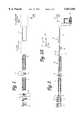
- FIG. 1is a top view of a manufacturing line for structural foam panels.
- FIG. 2is a side view of a manufacturing line for structural foam panels.
- FIG. 2Aillustrates positions assumed by a foam probe.
- FIGS. 3A-3Dshow stiffeners aligned and partially attached to top and bottom skins.
- FIG. 4is a perspective view of a structural wall made up of a plurality of interconnecting structural foam panels.
- FIG. 5is a sectional view of a separated pair of abutted panels edges.
- FIG. 6A and 6Bare a top and side views, respectively, of a section of the assembly line showing the position of the foam probe in its inserted and retracted mode.
- FIG. 7is a schematic side view showing how the foam probe fits between the skins upstream from where the foam is injected from the end of the probe.
- FIGS. 1 and 2illustrate the process for manufacturing the foam panels and an assembly line for manufacturing the same.
- FIG. 1is a top view of the manufacturing line for the process
- FIG. 2is a side view of the manufacturing line for the process.
- a top skin decoiler 1decoils top skin 3 and feeds the top skin 3 to a first straightener 5, while bottom decoiler 2 decoils bottom skin 4 and feeds the bottom skin 4 to a first roll former 7. Both skins 3 and 4 are made of metal.
- the top skin 3is threaded while passing through the first straightener 5.
- a top pallet uncoiler 6releases a top stiffener 21 to the first straightener 5 and the top stiffener 21 is also threaded while passing through the first straightener 5, and aligned and partially attached to an edge of the top skin 3 as shown in FIG. 3C.
- top skin 3 and the bottom skin 4are fed to a first roll former 7, respectively.
- first roll former 7the top skin 3 including the top stiffener 21 is formed into a structural shape to form abutting attaching edges 45 and 46 (See FIGS. 4 and 5).
- a shaped top skin 8 and the bottom skin 4are then fed to a second straightener 9.
- the bottom skin 4is threaded while passing through the second straightener 9.
- a bottom pallet uncoiler 11releases a bottom stiffener 22 to the second straightener 9, and the bottom stiffener 22 is also threaded while passing through the second straightener 9, and aligned and partially attached to an edge of the bottom skin 4 as shown in FIG. 3D.
- the shaped top skin 8 and bottom skin 4 including the bottom stiffener 22, respectively,are then fed to a second roll former 13 and pressure foam conveyor 15, consecutively.
- the bottom skin 4 including the bottom stiffener 22is formed into a structural shape to form abutting attaching edges 45 and 46 (See FIGS. 4 and 5).
- the shaped top skin 8 and the shaped bottom skin 10are aligned and spaced in a proper dimension.
- a spacing between the second roll former 13 and pressure foam conveyor 15is ranged between 20 feet to 40 feet, and this spacing is particularly important to allow the shaped top skin 8 and the shaped bottom skin 10 to be brought into alignment with an injection of foam 19 (not shown) to form an integrated continuous panel 23.
- the preferred spacingis 30 feet.
- the pressure foam conveyor 15presses the integrated continuous panel 23 which is the integration of the shaped skins 8 and 10 and foam 19 (not shown) which is injected by a foam probe 20.
- the foam probe 20is rotatable 180 degrees on a post 81 and is in a foam injecting position 20A when the shaped skins 8 and 10 are aligned and put on the pressure foam conveyor 15.
- the foam probe 20is in a withdrawal position 20B when there are no skins put on the pressure foam conveyor 15.
- An air cylinder 24 connected to the foam probe 20rotates the foam probe 20 between the foam injection position 20A and the withdrawal position 20B.
- the continuous pressed panel 23is then cured in a oven 25 of the pressure foam conveyor 15.
- the foam 19should be injected where the top skin 3 and bottom skin 4 are as close together as they shall be in the finished product. This is after the stiffeners 21 and 22 have been formed and attached to the skins. This leaves too little space between member 62 and skin 42 (see FIG. 5) through which to insert the foam probe 20.
- the foam probe 20has a curved shape, as seen in FIGS. 2A and 6A.
- the probe 20passes between the stiffeners 21 and 22 at point 98, where the top skin 3 and bottom skin 4 are still farther apart.
- the probethen curves downstream in the flow of the process while between the top skin 3 and bottom skin 4.
- the foam 19(not shown) is then ejected out of the end of foam probe 20 at point 99, where the top skin 3 and bottom skin 4 are closer together.
- the probe 20may be rotated out of the way of the conveyor and the skins 3 and 4 to facilitate maintenance and the removal or installation of new rolls of skin 3 and 4.
- probe 20is shown only in cross-section as it passes between the stiffeners 21 and 22 attached to skins 3 and 4 before probe 20 curves downstream.
- the dotted linesshow the outer reaches of stiffeners 21 and 22, showing how, viewed from the side, the stiffeners overlap and leave no room for the insertion of probe 20 at point 99.
- Foam day tanks 82are shown which hold the foam 19 prior to injection through probe 20, and are connected to probe 20 with tubes and pumps (not shown).
- the continuous cured panel 27is then conveyed through a run out conveyor 17 to clamp and cut-off saw 18, consecutively.
- the clamp and cut-off saw 18cuts the continuous cured panel 27 to the proper size and shape to fabricate finished structural foam panels 29 according to specifications which vary depending on intended usage.
- the cured panel 27is still a continuous length of panel running through the manufacturing line until it is cut into discrete panels 29 at the cut-off saw 18. (For convenience of illustration, the panel 23 and 27 is shown as a segment, but it is a connected continuous panel until cut by the saw 18.)
- the specifications for cutting the panel 27are memorized in a computer 25, which communicates with and controls clamp and cut-off saw 18, and thereby controls the cutting activities depending on the specifications and usages.
- the clamp and cut-off saw 18also numbers the structural foam panels 29, which are the components and parts for kits for constructing buildings including homes, hotels, and hospitals.
- the computerFor each type of structure for which the panels are being made, the computer contains the specification for a complete kit of panels for one such structure.
- the computer 25controls the saw 18 to cut the continuous panel 27 into a complete kit of panels 29 for the selected building, numbering each panel to indicate its role in the kit. In this way the product of the continuous process can be a series of full building kits with numbered parts corresponding to the buildings selected.
- the process of manufacturing the panelsis executed by the continuous process assembly line.
- Each part of the assembly lineexecutes one or more steps in the process.
- the assembly linemay be computerized, partially computerized, automatic, semi-automatic, or manually controlled.
- the continuous processallows economies of scale, lower unit cost, and mass production, when compared with traditional batch processes.
- the steps in the processinclude decoiling the top and bottom skins 3 and 4 by decoilers, respectively, releasing the top and bottom stiffeners 21 and 22 by uncoilers 6 and 11, respectively, feeding the skins 3 and 4 to a first straightener 5, threading the top skin 3 and a top stiffener 21 in the first straightener 5, aligning and partially attaching the top stiffener 21 to the top skin 3, threading the bottom skin 4 and a bottom stiffener 22 in a second straightener 9, aligning and partially attaching the bottom stiffener 22 to the bottom skin 4, feeding both skins 3 and 4 including stiffeners 21 and 22, respectively, to roll formers 7 and 13, shaping both skins 3 and 4 into a structural shape to form abutting attaching edges 45 and 46 (see FIGS.
- the discrete finished panels and stiffeners themselvesmay be manufactured by other processes, including batch processes, and manual processes.
- the discrete finished panelsmay be made without use of the continuous assembly line.
- FIGS. 3A-3Dillustrate a detailed structure of a foam panel before the panel is formed into a structural shape.
- the top stiffener 21 and the bottom stiffener 22are partially attached to the top skin 3 and the bottom skin 4, respectively.
- the part where the stiffeners 21 and 22 are attached,is then formed into a structural shape to form abutting attaching edges 45 and 46 (see FIGS. 4 and 5).
- the preferred panel to be made at this timeis that as shown in FIGS. 4 and 5 hereof, and in U.S. Pat. No. 5,373,678, issued Dec. 20, 1994, by Hesser.
- the continuous manufacturing process and apparatus of the present inventioncan be used for any type of structural panel with two skins, and a foam core, with or without a stiffener, and related variations.
- a structural and insulated wall 40has a plurality of panels 41 interconnected to each other.
- Each panelhas an outer skin 42 and an inner skin 43 spaced by a uniform thick insulating material which is foam 19, such as a polystyrene or polyurethane rigid foam, to form a lightweight structural panel 29.
- a uniform thick insulating materialwhich is foam 19, such as a polystyrene or polyurethane rigid foam, to form a lightweight structural panel 29.
- Each panelhas abutting attaching edges 45 and 46.
- Edge 45has a metal lined tongue 47 and a metal lined groove 48 in which the metal lining continues from the inner and outer skins 42 and 43. However, the tongue 47 and the groove 48 are spaced from each other to leave an angled insulating material 50 which, when the panels are connected, will press against the insulating material 51 of the next adjacent panel.
- the panel edge 46has a metal lined groove 52 which exactly coincides and coacts with the tongue 47 and has a tongue 53 with the metal lined groove 48.
- the abutting edge interconnection of the panelshas an elongated reinforced metal member 55 which may be a steel or heavy aluminum reinforcing member.
- Member 55has a channel portion 56 formed to fit around the metal lined groove 48 in the back thereof, so that the groove 48 is lined all the way around by the reinforcing member 55.
- Member 55then has an inner skin attaching portion 57 formed along the inner skin 43 of the panel 41 and has an additional perpendicular extending flange 58.
- the reinforcing member 55forms a channel facing lengthwise of the panels as well as transverse to the panels to greatly strengthen the panel in both directions when the panel and reinforcing members are anchored together to a structure.
Landscapes
- Engineering & Computer Science (AREA)
- Mechanical Engineering (AREA)
- Casting Or Compression Moulding Of Plastics Or The Like (AREA)
- Laminated Bodies (AREA)
- Building Environments (AREA)
- Automatic Assembly (AREA)
Abstract
Description
Claims (4)
Priority Applications (14)
| Application Number | Priority Date | Filing Date | Title |
|---|---|---|---|
| US08/590,669US5827458A (en) | 1996-01-24 | 1996-01-24 | Continuous method of making structural foam panels |
| CA002243074ACA2243074C (en) | 1996-01-24 | 1997-01-24 | Method and apparatus for structural foam panels |
| DE69723304TDE69723304D1 (en) | 1996-01-24 | 1997-01-24 | METHOD AND DEVICE FOR PRODUCING FOAM PANELS |
| ARP970100314AAR005560A1 (en) | 1996-01-24 | 1997-01-24 | CONTINUOUS ASSEMBLY PROCESS TO MAKE STRUCTURAL FOAM PANELS |
| PCT/US1997/001112WO1997027036A1 (en) | 1996-01-24 | 1997-01-24 | Method and apparatus for structural foam panels |
| AU18374/97AAU1837497A (en) | 1996-01-24 | 1997-01-24 | Method and apparatus for structural foam panels |
| AT97903944TATE244121T1 (en) | 1996-01-24 | 1997-01-24 | METHOD AND DEVICE FOR PRODUCING FOAM PANELS |
| BR9707068-8ABR9707068A (en) | 1996-01-24 | 1997-01-24 | Continuous assembly process and continuous assembly line to manufacture structural foam panels, foam probe and programmable device, process to be performed with the help of a computer and computer-readable memory. |
| CN97191843ACN1081526C (en) | 1996-01-24 | 1997-01-24 | Method and apparatus for structural foam panels |
| HK99102675.0AHK1017635B (en) | 1996-01-24 | 1997-01-24 | Method and apparatus for structural foam panels |
| RU98115852/12ARU2173263C2 (en) | 1996-01-24 | 1997-01-24 | Method and device for manufacturing foam plastic building panels |
| PL97328160APL182629B1 (en) | 1996-01-24 | 1997-01-24 | Method of and apparatus for making structural foamed plastic panels |
| EP97903944AEP0954421B1 (en) | 1996-01-24 | 1997-01-24 | Method and apparatus for structural foam panels |
| CO97003390ACO4650200A1 (en) | 1996-01-24 | 1997-01-24 | METHOD AND APPARATUS FOR STRUCTURAL FOAM PANELS |
Applications Claiming Priority (1)
| Application Number | Priority Date | Filing Date | Title |
|---|---|---|---|
| US08/590,669US5827458A (en) | 1996-01-24 | 1996-01-24 | Continuous method of making structural foam panels |
Publications (1)
| Publication Number | Publication Date |
|---|---|
| US5827458Atrue US5827458A (en) | 1998-10-27 |
Family
ID=24363191
Family Applications (1)
| Application Number | Title | Priority Date | Filing Date |
|---|---|---|---|
| US08/590,669Expired - LifetimeUS5827458A (en) | 1996-01-24 | 1996-01-24 | Continuous method of making structural foam panels |
Country Status (13)
| Country | Link |
|---|---|
| US (1) | US5827458A (en) |
| EP (1) | EP0954421B1 (en) |
| CN (1) | CN1081526C (en) |
| AR (1) | AR005560A1 (en) |
| AT (1) | ATE244121T1 (en) |
| AU (1) | AU1837497A (en) |
| BR (1) | BR9707068A (en) |
| CA (1) | CA2243074C (en) |
| CO (1) | CO4650200A1 (en) |
| DE (1) | DE69723304D1 (en) |
| PL (1) | PL182629B1 (en) |
| RU (1) | RU2173263C2 (en) |
| WO (1) | WO1997027036A1 (en) |
Cited By (7)
| Publication number | Priority date | Publication date | Assignee | Title |
|---|---|---|---|---|
| US6438906B1 (en)* | 2000-07-18 | 2002-08-27 | Paul Janssens-Lens | Safe room |
| US6467143B1 (en)* | 1999-12-30 | 2002-10-22 | Nam & Nam | Automatic door panel producing apparatus |
| WO2003076730A3 (en)* | 2002-03-04 | 2004-03-18 | Joseph A Deming | Insulated weather-resistant interlocking roof system and method |
| US20090100763A1 (en)* | 2004-11-18 | 2009-04-23 | Clopay Building Products Company, Inc. | Method of making an optimized overhead sectional door and associated door panel |
| US20090272069A1 (en)* | 2008-05-02 | 2009-11-05 | Bennett Iii Thomas B | Movable barriers having transverse stiffeners and methods of making the same |
| US20120246939A1 (en)* | 2011-04-01 | 2012-10-04 | Odom Construction | Integrated Panelization |
| CN105856318A (en)* | 2016-05-30 | 2016-08-17 | 芜湖美威包装品有限公司 | Packing foam cutting device |
Families Citing this family (2)
| Publication number | Priority date | Publication date | Assignee | Title |
|---|---|---|---|---|
| CN103009542B (en)* | 2012-12-28 | 2015-04-08 | 王洪文 | Composite board manufacturing system and manufacturing method thereof |
| CN110216828B (en)* | 2019-05-31 | 2021-06-22 | 安徽信盟装备股份有限公司 | A multi-station vacuum forming machine |
Citations (7)
| Publication number | Priority date | Publication date | Assignee | Title |
|---|---|---|---|---|
| US3792141A (en)* | 1972-05-26 | 1974-02-12 | W Offutt | Method of structural fabrication |
| US3846524A (en)* | 1972-01-17 | 1974-11-05 | Dura Plex Ind | Structural panel and method of making same |
| US3867494A (en)* | 1973-03-06 | 1975-02-18 | Owens Corning Fiberglass Corp | Method and apparatus for producing fiber reinforced organic foam |
| US4255105A (en)* | 1979-06-15 | 1981-03-10 | Bayer Aktiengesellschaft | Equipment for the continuous production of foam boards |
| US4362678A (en)* | 1980-01-18 | 1982-12-07 | The Celotex Corporation | Method of making polyisocyanurate foam laminate |
| US5254301A (en)* | 1988-03-29 | 1993-10-19 | Ferris Mfg. Corp. | Process for preparing a sheet of polymer-based foam |
| US5533312A (en)* | 1994-11-30 | 1996-07-09 | Steel-Craft Door Products Ltd. | Composite panel having interlocked skins and a bonded foam core |
Family Cites Families (7)
| Publication number | Priority date | Publication date | Assignee | Title |
|---|---|---|---|---|
| DE2231084A1 (en)* | 1972-06-24 | 1974-01-03 | Hennecke Gmbh Maschf | DEVICE FOR THE CONTINUOUS PRODUCTION OF FOAM BLOCKS |
| GB1510140A (en)* | 1975-12-22 | 1978-05-10 | Schlegel Corp | Continuous moulding method and apparatus |
| DE2819709C2 (en)* | 1978-05-05 | 1980-07-10 | Hoesch Werke Ag, 4600 Dortmund | Method and device for the continuous production of foam sheets, in particular provided with at least one cover layer |
| US4238544A (en)* | 1979-05-16 | 1980-12-09 | Virginia Door Co. | Door panel and manner of making |
| US4866630A (en)* | 1986-04-14 | 1989-09-12 | Armstrong Blum Mfg. | Programmable band saw and method of sawing |
| SU1691128A1 (en)* | 1988-10-06 | 1991-11-15 | Филиал Всесоюзного Научно-Исследовательского И Проектно-Конструкторского Института Металлургического Машиностроения Им.А.И.Целикова,Г.Славянск | Line for manufacturing of laminar panels |
| US5089191A (en)* | 1990-03-28 | 1992-02-18 | Woodbridge Foam Corporation | Process for manufacturing a padded element |
- 1996
- 1996-01-24USUS08/590,669patent/US5827458A/ennot_activeExpired - Lifetime
- 1997
- 1997-01-24PLPL97328160Apatent/PL182629B1/ennot_activeIP Right Cessation
- 1997-01-24WOPCT/US1997/001112patent/WO1997027036A1/enactiveIP Right Grant
- 1997-01-24RURU98115852/12Apatent/RU2173263C2/ennot_activeIP Right Cessation
- 1997-01-24DEDE69723304Tpatent/DE69723304D1/ennot_activeExpired - Lifetime
- 1997-01-24ATAT97903944Tpatent/ATE244121T1/ennot_activeIP Right Cessation
- 1997-01-24CACA002243074Apatent/CA2243074C/ennot_activeExpired - Fee Related
- 1997-01-24EPEP97903944Apatent/EP0954421B1/ennot_activeExpired - Lifetime
- 1997-01-24ARARP970100314Apatent/AR005560A1/enunknown
- 1997-01-24AUAU18374/97Apatent/AU1837497A/ennot_activeAbandoned
- 1997-01-24COCO97003390Apatent/CO4650200A1/enunknown
- 1997-01-24CNCN97191843Apatent/CN1081526C/ennot_activeExpired - Fee Related
- 1997-01-24BRBR9707068-8Apatent/BR9707068A/ennot_activeIP Right Cessation
Patent Citations (7)
| Publication number | Priority date | Publication date | Assignee | Title |
|---|---|---|---|---|
| US3846524A (en)* | 1972-01-17 | 1974-11-05 | Dura Plex Ind | Structural panel and method of making same |
| US3792141A (en)* | 1972-05-26 | 1974-02-12 | W Offutt | Method of structural fabrication |
| US3867494A (en)* | 1973-03-06 | 1975-02-18 | Owens Corning Fiberglass Corp | Method and apparatus for producing fiber reinforced organic foam |
| US4255105A (en)* | 1979-06-15 | 1981-03-10 | Bayer Aktiengesellschaft | Equipment for the continuous production of foam boards |
| US4362678A (en)* | 1980-01-18 | 1982-12-07 | The Celotex Corporation | Method of making polyisocyanurate foam laminate |
| US5254301A (en)* | 1988-03-29 | 1993-10-19 | Ferris Mfg. Corp. | Process for preparing a sheet of polymer-based foam |
| US5533312A (en)* | 1994-11-30 | 1996-07-09 | Steel-Craft Door Products Ltd. | Composite panel having interlocked skins and a bonded foam core |
Cited By (11)
| Publication number | Priority date | Publication date | Assignee | Title |
|---|---|---|---|---|
| US6467143B1 (en)* | 1999-12-30 | 2002-10-22 | Nam & Nam | Automatic door panel producing apparatus |
| US6438906B1 (en)* | 2000-07-18 | 2002-08-27 | Paul Janssens-Lens | Safe room |
| WO2003076730A3 (en)* | 2002-03-04 | 2004-03-18 | Joseph A Deming | Insulated weather-resistant interlocking roof system and method |
| US20090100763A1 (en)* | 2004-11-18 | 2009-04-23 | Clopay Building Products Company, Inc. | Method of making an optimized overhead sectional door and associated door panel |
| US7861763B2 (en)* | 2004-11-18 | 2011-01-04 | Clopay Building Products Company, Inc. | Method of making an optimized overhead sectional door and associated door panel |
| US20090272069A1 (en)* | 2008-05-02 | 2009-11-05 | Bennett Iii Thomas B | Movable barriers having transverse stiffeners and methods of making the same |
| US20110108212A1 (en)* | 2008-05-02 | 2011-05-12 | Overhead Door Corporation | Movable barriers having transverse stiffeners and methods of making the same |
| US7955460B2 (en)* | 2008-05-02 | 2011-06-07 | Overhead Door Corporation | Movable barriers having transverse stiffeners and methods of making the same |
| US8220519B2 (en) | 2008-05-02 | 2012-07-17 | Overhead Door Corporation | Movable barriers having transverse stiffeners and methods of making the same |
| US20120246939A1 (en)* | 2011-04-01 | 2012-10-04 | Odom Construction | Integrated Panelization |
| CN105856318A (en)* | 2016-05-30 | 2016-08-17 | 芜湖美威包装品有限公司 | Packing foam cutting device |
Also Published As
| Publication number | Publication date |
|---|---|
| HK1017635A1 (en) | 1999-11-26 |
| PL328160A1 (en) | 1999-01-18 |
| BR9707068A (en) | 1999-12-28 |
| CN1081526C (en) | 2002-03-27 |
| EP0954421A4 (en) | 2000-06-07 |
| AR005560A1 (en) | 1999-06-23 |
| ATE244121T1 (en) | 2003-07-15 |
| CN1209767A (en) | 1999-03-03 |
| EP0954421B1 (en) | 2003-07-02 |
| WO1997027036A1 (en) | 1997-07-31 |
| EP0954421A1 (en) | 1999-11-10 |
| CA2243074A1 (en) | 1997-07-31 |
| RU2173263C2 (en) | 2001-09-10 |
| CA2243074C (en) | 2002-11-26 |
| AU1837497A (en) | 1997-08-20 |
| DE69723304D1 (en) | 2003-08-07 |
| PL182629B1 (en) | 2002-02-28 |
| CO4650200A1 (en) | 1998-09-03 |
Similar Documents
| Publication | Publication Date | Title |
|---|---|---|
| US5827458A (en) | Continuous method of making structural foam panels | |
| DE3877539T2 (en) | Circular formwork process for concrete washing. | |
| DE4426097A1 (en) | Process for the production of hollow body structures from sheet metal | |
| DE69125496T2 (en) | INTERFERING STRUCTURAL BODIES | |
| US6708384B2 (en) | Notched muntin bars having two finishes | |
| AT398053B (en) | METHOD AND PIPE CONNECTOR FOR THE CONTINUOUS PRODUCTION OF LAMINATED, THERMALLY INSULATED PIPES | |
| US20100178454A1 (en) | Equipment and method for obtaining profile sections made from composite material and profile section obtained by means of said method | |
| US1843064A (en) | Method of making reenforcing unions | |
| DE102009036583B4 (en) | Double belt system and method for producing a finished construction element | |
| CN102189384B (en) | Production method of cold bend B type steel | |
| DE1530934C3 (en) | ||
| US5933954A (en) | Method for fabricating a seamless H.V.A.C. trunk line adaptor | |
| AT7929U1 (en) | METHOD FOR PRODUCING A MULTICOLOOR GRP TUBE AND GRP TUBE PRODUCED THEREOF | |
| HK1017635B (en) | Method and apparatus for structural foam panels | |
| DE60316730T2 (en) | METHOD AND DEVICE FOR CONTINUOUS PRODUCTION OF CURVED INSULATING PLATES | |
| DE29703588U1 (en) | Device for producing a preferably closed hollow profile section by roll forming | |
| DE3211289A1 (en) | Apparatus for producing tubular lengths of insulating shells | |
| DE914844C (en) | Device for the production of thin-walled, bolted sheet metal pipes of great length | |
| EP0369063A1 (en) | Expansion element for construction and civil engineering work, method of making same and device to perform the method | |
| DE3034592A1 (en) | FITTING CAP KIT | |
| DE10138600A1 (en) | Multi-layer composite pipe production plant for different diameter pipes, has a plastic liner extruder and metal strip outer production section followed by diameter reduction units and a second extruder | |
| AT375296B (en) | METHOD AND DEVICE FOR PRODUCING TUBULAR INSULATION PANELS FROM EXPANDED PLASTIC | |
| JPH07180899A (en) | Method and device for composite spiral duct | |
| WO2011085776A1 (en) | Device for rollforming-profiling and bowing sections of metal strip | |
| AT270912B (en) | Device for producing hollow strands from glass |
Legal Events
| Date | Code | Title | Description |
|---|---|---|---|
| AS | Assignment | Owner name:PAUL F. JANSSENS-LENS, FLORIDA Free format text:ASSIGNMENT OF ASSIGNORS INTEREST;ASSIGNOR:MEADOWS, JAMES A.;REEL/FRAME:008100/0676 Effective date:19960116 | |
| FPAY | Fee payment | Year of fee payment:4 | |
| AS | Assignment | Owner name:ALTERNATIVE CONSTRUCTION COMPANY, INC., NEW YORK Free format text:ASSIGNMENT OF ASSIGNORS INTEREST;ASSIGNOR:JANSSENS, PAUL;REEL/FRAME:016164/0701 Effective date:20050121 | |
| REMI | Maintenance fee reminder mailed | ||
| REIN | Reinstatement after maintenance fee payment confirmed | ||
| FEPP | Fee payment procedure | Free format text:PETITION RELATED TO MAINTENANCE FEES FILED (ORIGINAL EVENT CODE: PMFP); ENTITY STATUS OF PATENT OWNER: SMALL ENTITY | |
| FEPP | Fee payment procedure | Free format text:PETITION RELATED TO MAINTENANCE FEES GRANTED (ORIGINAL EVENT CODE: PMFG); ENTITY STATUS OF PATENT OWNER: SMALL ENTITY | |
| FP | Lapsed due to failure to pay maintenance fee | Effective date:20061027 | |
| FPAY | Fee payment | Year of fee payment:8 | |
| SULP | Surcharge for late payment | ||
| AS | Assignment | Owner name:BRIDGEPOINTE MASTER FUND LTD., LLP, GEORGIA Free format text:SECURITY AGREEMENT;ASSIGNOR:ALTERNATIVE CONSTRUCTION COMPANY, INC.;REEL/FRAME:019658/0099 Effective date:20070702 | |
| PRDP | Patent reinstated due to the acceptance of a late maintenance fee | Effective date:20070815 | |
| STCF | Information on status: patent grant | Free format text:PATENTED CASE | |
| AS | Assignment | Owner name:BRIDGEPOINT MASTER FUND LTD., LLP, GEORGIA Free format text:ASSIGNMENT BY COURT ORDER;ASSIGNOR:ALTERNATIVE CONSTRUCTION COMPANY, INC.;REEL/FRAME:022773/0308 Effective date:20090130 | |
| FPAY | Fee payment | Year of fee payment:12 | |
| AS | Assignment | Owner name:SILVERWOOD TECHNOLOGIES, LLC, GEORGIA Free format text:FORECLOSURE OF SECURITY INTEREST;ASSIGNOR:ALTERNATIVE CONSTRUCTION COMPANY, INC.;REEL/FRAME:025608/0898 Effective date:20110107 | |
| AS | Assignment | Owner name:LAMINATION, INC., GEORGIA Free format text:ASSIGNMENT OF ASSIGNORS INTEREST;ASSIGNOR:SILVERWOOD TECHNOLOGIES, LLC;REEL/FRAME:027784/0709 Effective date:20111031 |