US5827291A - Suture anchor driver with suture retainer - Google Patents
Suture anchor driver with suture retainerDownload PDFInfo
- Publication number
- US5827291A US5827291AUS08/744,178US74417896AUS5827291AUS 5827291 AUS5827291 AUS 5827291AUS 74417896 AUS74417896 AUS 74417896AUS 5827291 AUS5827291 AUS 5827291A
- Authority
- US
- United States
- Prior art keywords
- suture
- driver
- anchor
- proximal end
- shaft
- Prior art date
- Legal status (The legal status is an assumption and is not a legal conclusion. Google has not performed a legal analysis and makes no representation as to the accuracy of the status listed.)
- Expired - Lifetime
Links
- 230000006835compressionEffects0.000claimsdescription29
- 238000007906compressionMethods0.000claimsdescription29
- 230000014759maintenance of locationEffects0.000claimsdescription24
- 238000000034methodMethods0.000claimsdescription16
- 210000000988bone and boneAnatomy0.000description15
- 239000007943implantSubstances0.000description9
- 210000004872soft tissueAnatomy0.000description9
- 238000004140cleaningMethods0.000description3
- 238000001356surgical procedureMethods0.000description3
- 210000001519tissueAnatomy0.000description3
- 238000003780insertionMethods0.000description2
- 230000037431insertionEffects0.000description2
- 238000012986modificationMethods0.000description2
- 230000004048modificationEffects0.000description2
- 208000027418Wounds and injuryDiseases0.000description1
- 230000000712assemblyEffects0.000description1
- 238000000429assemblyMethods0.000description1
- 230000005540biological transmissionEffects0.000description1
- 230000015556catabolic processEffects0.000description1
- 238000006731degradation reactionMethods0.000description1
- 230000001419dependent effectEffects0.000description1
- 238000002674endoscopic surgeryMethods0.000description1
- 230000002708enhancing effectEffects0.000description1
- 230000003116impacting effectEffects0.000description1
- 208000014674injuryDiseases0.000description1
- 210000003041ligamentAnatomy0.000description1
- 238000004519manufacturing processMethods0.000description1
- 239000000463materialSubstances0.000description1
- 229910052751metalInorganic materials0.000description1
- 239000002184metalSubstances0.000description1
- 150000002739metalsChemical class0.000description1
- 210000003205muscleAnatomy0.000description1
- 229920003023plasticPolymers0.000description1
- 239000004033plasticSubstances0.000description1
- 230000002787reinforcementEffects0.000description1
- 230000000717retained effectEffects0.000description1
- 230000001954sterilising effectEffects0.000description1
- 238000004659sterilization and disinfectionMethods0.000description1
- 239000000725suspensionSubstances0.000description1
- 210000002435tendonAnatomy0.000description1
- 230000008733traumaEffects0.000description1
Images


Classifications
- A—HUMAN NECESSITIES
- A61—MEDICAL OR VETERINARY SCIENCE; HYGIENE
- A61B—DIAGNOSIS; SURGERY; IDENTIFICATION
- A61B17/00—Surgical instruments, devices or methods
- A61B17/04—Surgical instruments, devices or methods for suturing wounds; Holders or packages for needles or suture materials
- A61B17/0401—Suture anchors, buttons or pledgets, i.e. means for attaching sutures to bone, cartilage or soft tissue; Instruments for applying or removing suture anchors
- A—HUMAN NECESSITIES
- A61—MEDICAL OR VETERINARY SCIENCE; HYGIENE
- A61B—DIAGNOSIS; SURGERY; IDENTIFICATION
- A61B17/00—Surgical instruments, devices or methods
- A61B17/04—Surgical instruments, devices or methods for suturing wounds; Holders or packages for needles or suture materials
- A61B17/0485—Devices or means, e.g. loops, for capturing the suture thread and threading it through an opening of a suturing instrument or needle eyelet
- A—HUMAN NECESSITIES
- A61—MEDICAL OR VETERINARY SCIENCE; HYGIENE
- A61B—DIAGNOSIS; SURGERY; IDENTIFICATION
- A61B17/00—Surgical instruments, devices or methods
- A61B17/04—Surgical instruments, devices or methods for suturing wounds; Holders or packages for needles or suture materials
- A61B17/0401—Suture anchors, buttons or pledgets, i.e. means for attaching sutures to bone, cartilage or soft tissue; Instruments for applying or removing suture anchors
- A61B2017/0409—Instruments for applying suture anchors
- A—HUMAN NECESSITIES
- A61—MEDICAL OR VETERINARY SCIENCE; HYGIENE
- A61B—DIAGNOSIS; SURGERY; IDENTIFICATION
- A61B17/00—Surgical instruments, devices or methods
- A61B17/04—Surgical instruments, devices or methods for suturing wounds; Holders or packages for needles or suture materials
- A61B2017/0496—Surgical instruments, devices or methods for suturing wounds; Holders or packages for needles or suture materials for tensioning sutures
Definitions
- the inventionrelates to a surgical instrument for inserting a surgical implant such as a suture anchor having an implantable body designed for insertion into tissue at a surgical site, the body having suture attached for securing selected tissue adjacent to the site. More particularly, the invention relates to an endoscopic surgical instrument for endoscopically driving a suture anchor having suture attached thereto.
- anchorsmay be used to attach soft tissue such as ligaments, tendons, muscles, etc. to a surface from which the soft tissue has become detached and may also be used to secure soft tissue to supplementary attachment sites for reinforcement.
- anchorsmay be used in bladder neck suspensions to attach a portion of the bladder to an adjacent bone surface.
- Such soft tissue attachmentmay be done during either open or closed surgical procedures, the latter being generally referred to as arthroscopic or endoscopic surgery.
- arthroscopicand “endoscopic” may be used interchangeably herein and are intended to encompass arthroscopic, endoscopic, laparoscopic, hysteroscopic or any other similar surgical procedures performed with elongated instruments inserted through small natural or artificial openings in the body.
- suture anchorsIn procedures requiring suturing of soft tissue to bone, the suture is first anchored by the so-called suture anchors to the bone before suturing of the soft tissue.
- the prior artincludes numerous types of suture anchors adapted to be secured in the bone, sometimes directly, in one step, and sometimes in pre-drilled holes or tunnels.
- suture anchoris used broadly and will be understood to refer to devices having a similar structure even if material other than suture is connected to the device.
- Some prior art suture anchorsare elongated and have annular ribs or radially extending barbs and are required to be pushed or hammered directly into bone or into a pre-formed bone tunnel (exemplified by U.S. Pat. Nos.
- Pushing an anchor into placehas the disadvantage of potential trauma and damage to surrounding bone tissue, and has limited applicability where the location of the bone tunnel or pre-drilled hole is not axially aligned with (for example) an arthroscopic portal to permit transmission of the impacting force through an impactor to the anchor.
- An impacted suture anchoris not easily removable without damaging the bone into which it has been placed. Consequently, threaded suture anchors are often used as exemplified by U.S. Pat. Nos.
- the insertion proceduremay enable direct threading of the anchor into the bone or it may sometimes require that a pilot hole first be drilled into the bone, the hole then either enabling an anchor to be screwed in or enabling threads to be tapped to receive the anchor.
- Both push-in and turn-in suture anchorshave an implantable body with a distal end for being inserted into the bone and a proximal end serving as a drive portion.
- Each type of anchorhas an eyelet somewhere along its length (or some other means) for attaching a suture to the body and is implanted by a driver adapted to engage the drive portion to either push it or turn it into a selected site.
- the anchoris usually driven with suture already threaded through the eyelet and the suture is then passed through tissue to be supported by the anchor, the suture ends then being tied or otherwise secured to the soft tissue.
- Suture anchorsmay be either pre-loaded with suture already attached or they may be provided to the user without suture.
- the anchorsmay be packaged already assembled with a driver but in both cases, as stated above, the suture anchor is driven into the bone with the suture attached. Consequently, the driver must somehow accommodate the proximal ends of suture extending proximally from the anchor body as the latter is pushed or turned into the bone.
- suture attached to push-in anchorssimply follows the path of the driver in an uncontrolled manner such as shown, for example, in U.S. Pat. No. 5,207,679 (Li) and U.S. Pat. No. 5,217,486 (Rice et al.). It is known, however, to control the ends of the suture in other types of push-in suture anchor embodiments such as shown in U.S. Pat. No. 5,258,016 (DiPoto et al.). This patent shows the proximal ends of suture being wrapped around one or more retention posts attached to the proximal end of the driver.
- the driveris cannulated throughout its length and the suture extends through the driver from its distal tip (to which the suture anchor is secured) to its proximal end where it is wrapped around a retention post.
- Another push-in type driveris shown in U.S. Pat. No. 5,522,845 (Wenstrom Jr.) in which the proximal ends of the suture are wrapped around the proximal end of the driver in a recess between a toroidal grommet (O-ring) and the driver shaft.
- the grommetmay stretch and break with use, especially with a large number of sterilization cycles, so such drivers are not optimized for repeated use.
- the grommet designrequires the user to aim the suture into the small tight space next to the grommet and is not easily adaptable to changes in suture size. All such drivers either require excessive manipulation of the proximal ends of the suture or do not securely hold the suture. Furthermore, such drivers have a frictional grip on the suture which is dependent on the suture diameter. A simpler and more secure suture retaining device would be preferable, especially for endoscopic applications. It would also be preferable to have a suture retaining device that operates independently of the suture size.
- a userneed simply remove the suture anchor/driver assembly from its package and place the suture anchor at the surgical site (manually or, preferably, with a powered drill).
- These devicesare not reusable and impractical for use if the surgeon must thread the suture through the suture anchor prior to use or in a variety of other situations
- a drivermay occasionally need to be re-loaded if a suture anchor is incorrectly placed, if the anchor should become dislodged from the driver prematurely, etc.
- the driverfor driving a suture anchor having suture attached thereto.
- the drivercomprises an elongated shaft having a proximal end, a distal end and an anchor receiving means at the distal end of the shaft for receiving a suture anchor.
- a throughboreenables suture to pass from the distal end to the proximal end of the shaft and a suture retaining means at the proximal end of the shaft holds the suture securely.
- the holding meanscomprises a fixed retention means immovably secured to the shaft for guiding the suture in a predetermined direction, a movable compression means and a spring for urging the compression means toward the fixed retention means to retain the suture.
- the inventionalso resides in a method for securing a suture anchor, with suture attached thereto, to a driver having a proximal end and a distal end comprising the steps of passing the suture from the distal end to the proximal end and providing at the proximal end a spring actuated suture retaining means for retaining suture.
- the retaining meanscomprises a fixed retention means immovably secured to the driver for guiding the suture in a predetermined direction, a movable compression means movably attached to the driver and a spring for urging the compression means toward the fixed retention means.
- the methodfurther comprises retracting and holding the compression means, passing the suture between the fixed retention means and the compression means and then releasing the compression means to thereby secure the suture between it and the fixed retention means.
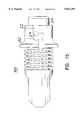
- FIG. 1is a front perspective view of a suture anchor driver constructed in accordance with the principles of this invention.
- FIG. 2is a top plan view of FIG. 1 showing the suture retaining means in a closed position, without suture.
- FIGS. 3 and 3Aare side elevational views of prior art suture anchors.
- FIG. 4is a side elevational view of a prior art suture anchor with a suture threaded through its proximal end.
- FIG. 5is a side elevational view of the driver of FIG. 1 assembled with a suture threader.
- FIG. 6is a view of FIG. 5 showing the step of threading the suture of FIG. 4 through the suture threader of FIG. 5.
- FIG. 7is a view of another step of the method of using the invention in which the suture anchor is seated at the distal tip of the driver.
- FIG. 8is a view showing another step in the procedure in which the suture is wrapped around the proximal end of the driver.
- FIG. 9is an end view of FIG. 8.
- FIG. 10is a view showing the next step in the procedure in which the driver frictionally engages the suture wrapped around its proximal end.
- FIG. 11is a front perspective view of an alternate embodiment of a suture anchor driver constructed in accordance with the principles of this invention.
- FIG. 12is a top plan view of FIG. 11.
- FIG. 13is a side elevational view of another alternate embodiment of a suture anchor driver constructed in accordance with the principles of this invention.
- FIG. 14is a front perspective view of the proximal portion of the embodiment of FIG. 13.
- FIG. 15is a plan view of another alternate embodiment of a portion of the embodiment of FIG. 14.
- driver 10comprises a cannulated drive shaft 12 having an axis 13, an implant retaining portion 14 at its distal end 16 and a handle portion 18 at its proximal end 20.
- Throughbore 22extends from distal end 16 to proximal end 20.
- Driver 10is intended for use with either a turn-in or push-in implant such as anchor 30 (FIG. 3) or anchor 30a (FIG. 3A), respectively.
- anchor 30FIG. 3
- anchor 30aFIG. 3A
- the component parts of each anchorare similar and will be numbered the same except that the push-in anchor parts will have the suffix "a”.
- Suture anchors 30 and 30aeach have an implantable body 32 and 32a, the former having a drill tip 33 and flute 34 at its distal end while the latter has a rounded tip 33a.
- the body of anchor 30has a thread 35 while that of 30a has a plurality of annular ribs 35a.
- Anchors 30 and 30ahave non-circular drive portions 37 and 37a which are adapted to be received in the distal implant retaining portion 14 of driver 10.
- driver 10captures and secures either implant to itself by means of tension translated to the implant via suture 38 that is passed through the eyelet of the implant.
- the distal end 16is provided with a non-circular aperture (at 14) to receive the suture anchor drive portion 37 or 37a, as the case may be.
- Handle portion 18preferably has a larger diameter than shaft 12 to facilitate its manipulation and its outer surface 40 has an elongated annular recess 42 around its circumference that is bounded by distal and proximal shoulders 44 and 46, respectively.
- Recess 42retains a coil spring 48 and a longitudinally slidable cylindrical sleeve 50.
- the diameter and shape of sleeve 50may vary. For example, as shown in FIGS. 1 and 2 the diameter of the sleeve is equal to that of the adjacent proximal end 51 of the handle while in FIGS. 11 and 12 it is greater.
- An annular groove 53enables a user to operate sleeve 50 from any annular position about the axis of driver 10.
- a fixed, radially outwardly extending post 52is secured to the proximal end 51 of handle 18 and is used for guiding suture 36 into and around the recess 42 (best seen in FIGS. 8 and 9). While in the preferred embodiment post 52 is situated preferably immediately adjacent proximal shoulder 46 to guide suture directly into recess 42, it will be understood that other guiding structures may be suitable (for example, if the lead-in radial channel 77 described below is deep enough, a separate guide post may be unnecessary).
- the distal end 60 of spring 48is longitudinally held in position by distal shoulder 44 at one end of recess 42 while the proximal end 62 of the spring lies against the distal end surface 64 of cylindrical sleeve 50.
- the structure at the proximal end of driver 10thus comprises a suture retainer because suture passing through the bore of the driver and connected to a suture anchor at the distal tip of the driver will be captured between the proximal surface 66 of sleeve 50 and proximal shoulder 46 of recess 42 due to the force of spring 48 against the distal end of the sleeve.
- the compression force of the spring against the sleevecauses a friction fit between the suture and sleeve which prevents the suture from sliding and thus prevents the anchor from disengaging from the distal tip of the driver.
- the springalso enables the retention mechanism to exert a force on the suture that is independent of suture size.
- FIGS. 4-10The method of using the driver is shown in FIGS. 4-10 with respect to suture anchor 30a. It will be understood that this method facilitates capturing distal parts of the suture ends in a suture retaining means at the proximal end of the driver.
- Suture 38is threaded through eyelet 36a of the suture anchor 30a (FIG. 4) and the two ends 38a and 38b of the suture 38 are passed through bore 22 of the cannulated driver from the distal tip 16 and out the proximal end 20.
- the passage of the suture through the driver boreis accomplished easily with a conventional suture threader 70 (FIG. 5), the loop 72 of which receives the suture ends (FIG. 6) and is then pulled back out of the bore in the direction of arrow 73.
- Cylindrical sleeve 50is slid distally (FIG. 8) to expose an annular proximal-most portion 76 of recess 42 while suture ends 38a, 38b coming out of the proximal end of bore 22 are guided into a radial channel 77, around post 52 (FIG. 9) in order to alter the suture direction and then around and into the distal end of recess 42 between proximal shoulder 46 and the proximal surface 66 of sleeve 50.
- FIG. 9shows the suture loosely wrapped about handle recess 42 for clarity; in use it is tighter, as shown in FIGS. 8 and 10.
- the retraction of the sleeveexposes a large area of the recess so suture of any size (within a range limited by the size of throughbore 22) can be easily wound around recess 42 without much attention by a user.
- the sleeveis then released (FIG. 10) allowing spring 48 to force it proximally, thus capturing suture 38 between the sleeve and the proximal shoulder of the recess.
- the cylindrical shape of the sleeve (and annular groove 53)enables it to be activated from any direction around the driver axis, it will be understood that other shapes and structures will be suitable.
- a throughbore 22to pass the suture from the distal end to the proximal end of the driver
- a channel(not shown) on the outer surface of the driver (or some other means for communicating the suture to the proximal end) could be used.
- Handle 18may be provided with a pair of finger recesses 80 and 82 and friction enhancing ridges 84.
- the proximal end 51 of handle 18may be threadably (or otherwise detachably) attached to a body portion (extending a length 88) to facilitate disassembly and cleaning by allowing the spring and sleeve to be removed.
- FIGS. 11 and 12An alternate embodiment of the invention is shown in FIGS. 11 and 12 as suture anchor driver 100 which differs from driver 10 only in the configuration of handle portion 118. More particularly, this embodiment differs from driver 10 primarily in the outer diameter of cylindrical sleeve 150.
- Sleeve 150has a distal shoulder 164 and a proximal shoulder 166, the diameter of each of which is the same and such that proximal shoulder 166 extends radially outwardly to define an annular compression surface 167 which extends radially outwardly as much as pin 152.
- pin 152serves to guide and retain the suture.
- FIGS. 13 and 14Another alternate embodiment of the invention is shown in FIGS. 13 and 14 as suture anchor driver 200 which differs from driver 10 only in the configuration of handle portion 218.
- Handle portion 218has a recess 220 bounded by a single distal shoulder 222, the diameter of recess portion 220 being uniform from shoulder 222 to the proximal end 230 of the driver.
- a fixed retention post 232is secured to the handle and a cylindrical sleeve 240 is provided with a post 242 extending from its circumferential outer surface adjacent a slot 244. The slot enables post 242 to be positioned contiguously with post 232.
- Sleeve 240 and post 242are movable as a unit biased by spring 246 and it will be understood that suture is retained in this embodiment by a friction fit between posts 232 and 242.
- Post 232may be threaded into the handle so that it may be easily removed to facilitate the disassembly and cleaning of this embodiment.
- an alternate embodiment 300 of handle 218utilizes all of the features described above with respect to driver 200 except that cylindrical sleeve 240 is replaced by cylindrical sleeve 310 having an S-shaped channel 312 extending through the body of the sleeve.
- the embodimentmay utilize posts similar to post 232 and 242 although they are omitted for clarity.
- the movable post(comparable to 242) would, for example, be on the diametrically opposite side of the sleeve from channel 312 and not seen in FIG. 15.
- Channel 312enables sleeve 310 to be removed from body 314 of the handle portion by rotating the sleeve about the axis of the handle and placing channel 212 in alignment with the fixed post (comparable to 232).
- Manipulating the fixed postrepresented by phantom circle 214) through the S-shaped channel 312 would enable sleeve 310 to be moved proximally past the fixed pin so the device could be disassembled for cleaning.
- the embodiments disclosed hereinmay be made either reusable or disposable and either pre-loaded or not.
- the various components of the driversmay be made of biocompatible metals or plastics which, if designed for reuse, are sterilizable without the degradation suffered by prior art devices such as grommets and the like.
Landscapes
- Health & Medical Sciences (AREA)
- Surgery (AREA)
- Life Sciences & Earth Sciences (AREA)
- Biomedical Technology (AREA)
- Nuclear Medicine, Radiotherapy & Molecular Imaging (AREA)
- Engineering & Computer Science (AREA)
- Rheumatology (AREA)
- Heart & Thoracic Surgery (AREA)
- Medical Informatics (AREA)
- Molecular Biology (AREA)
- Animal Behavior & Ethology (AREA)
- General Health & Medical Sciences (AREA)
- Public Health (AREA)
- Veterinary Medicine (AREA)
- Surgical Instruments (AREA)
Abstract
Description
1. Field of the Invention
The invention relates to a surgical instrument for inserting a surgical implant such as a suture anchor having an implantable body designed for insertion into tissue at a surgical site, the body having suture attached for securing selected tissue adjacent to the site. More particularly, the invention relates to an endoscopic surgical instrument for endoscopically driving a suture anchor having suture attached thereto.
2. Description of the Prior Art
In the course of certain surgical procedures, soft tissue is secured to a selected bone surface either directly, via some type of implant, or indirectly via an implant (i.e. an anchor) to which suture is attached, the suture then being tied to the soft tissue to hold it in place. Anchors may be used to attach soft tissue such as ligaments, tendons, muscles, etc. to a surface from which the soft tissue has become detached and may also be used to secure soft tissue to supplementary attachment sites for reinforcement. For example, in urological applications anchors may be used in bladder neck suspensions to attach a portion of the bladder to an adjacent bone surface. Such soft tissue attachment may be done during either open or closed surgical procedures, the latter being generally referred to as arthroscopic or endoscopic surgery. The terms "arthroscopic" and "endoscopic" may be used interchangeably herein and are intended to encompass arthroscopic, endoscopic, laparoscopic, hysteroscopic or any other similar surgical procedures performed with elongated instruments inserted through small natural or artificial openings in the body.
In procedures requiring suturing of soft tissue to bone, the suture is first anchored by the so-called suture anchors to the bone before suturing of the soft tissue. The prior art includes numerous types of suture anchors adapted to be secured in the bone, sometimes directly, in one step, and sometimes in pre-drilled holes or tunnels. The term "suture anchor" is used broadly and will be understood to refer to devices having a similar structure even if material other than suture is connected to the device. Some prior art suture anchors are elongated and have annular ribs or radially extending barbs and are required to be pushed or hammered directly into bone or into a pre-formed bone tunnel (exemplified by U.S. Pat. Nos. 5,102,421 (Anspach, Jr.); 5,141,520 (Goble et al.); 5,100,417 (Cerier et al.); 5,224,946 (Hayhurst et al.) and 5,261,914 (Warren)). Pushing an anchor into place has the disadvantage of potential trauma and damage to surrounding bone tissue, and has limited applicability where the location of the bone tunnel or pre-drilled hole is not axially aligned with (for example) an arthroscopic portal to permit transmission of the impacting force through an impactor to the anchor. An impacted suture anchor is not easily removable without damaging the bone into which it has been placed. Consequently, threaded suture anchors are often used as exemplified by U.S. Pat. Nos. 5,156,616 (Meadows et al.) and 4,632,100 (Somers et al.). Depending upon the type of threaded anchor, the insertion procedure may enable direct threading of the anchor into the bone or it may sometimes require that a pilot hole first be drilled into the bone, the hole then either enabling an anchor to be screwed in or enabling threads to be tapped to receive the anchor.
Both push-in and turn-in suture anchors have an implantable body with a distal end for being inserted into the bone and a proximal end serving as a drive portion. Each type of anchor has an eyelet somewhere along its length (or some other means) for attaching a suture to the body and is implanted by a driver adapted to engage the drive portion to either push it or turn it into a selected site. The anchor is usually driven with suture already threaded through the eyelet and the suture is then passed through tissue to be supported by the anchor, the suture ends then being tied or otherwise secured to the soft tissue. Suture anchors may be either pre-loaded with suture already attached or they may be provided to the user without suture. In the former case, the anchors may be packaged already assembled with a driver but in both cases, as stated above, the suture anchor is driven into the bone with the suture attached. Consequently, the driver must somehow accommodate the proximal ends of suture extending proximally from the anchor body as the latter is pushed or turned into the bone.
It is preferable to control the suture extending proximally from the suture anchor. In some instances the suture attached to push-in anchors simply follows the path of the driver in an uncontrolled manner such as shown, for example, in U.S. Pat. No. 5,207,679 (Li) and U.S. Pat. No. 5,217,486 (Rice et al.). It is known, however, to control the ends of the suture in other types of push-in suture anchor embodiments such as shown in U.S. Pat. No. 5,258,016 (DiPoto et al.). This patent shows the proximal ends of suture being wrapped around one or more retention posts attached to the proximal end of the driver. In one embodiment shown by DiPoto et al., the driver is cannulated throughout its length and the suture extends through the driver from its distal tip (to which the suture anchor is secured) to its proximal end where it is wrapped around a retention post. The tighter the suture is wound, the better it is held. Another push-in type driver is shown in U.S. Pat. No. 5,522,845 (Wenstrom Jr.) in which the proximal ends of the suture are wrapped around the proximal end of the driver in a recess between a toroidal grommet (O-ring) and the driver shaft. The grommet may stretch and break with use, especially with a large number of sterilization cycles, so such drivers are not optimized for repeated use. Additionally, the grommet design requires the user to aim the suture into the small tight space next to the grommet and is not easily adaptable to changes in suture size. All such drivers either require excessive manipulation of the proximal ends of the suture or do not securely hold the suture. Furthermore, such drivers have a frictional grip on the suture which is dependent on the suture diameter. A simpler and more secure suture retaining device would be preferable, especially for endoscopic applications. It would also be preferable to have a suture retaining device that operates independently of the suture size.
Drivers used for driving turn-in anchors must accommodate the proximal ends of the suture extending from the anchor since these ends would otherwise tend to get twisted and tangled and interfere with the procedure. The aforementioned Wenstrom Jr. patent shows one suitable driver and U.S. Pat. Nos. 5,411,506 (Goble et al.) and 5,411,523 (Goble) show another type of driver which secures the proximal ends of the suture to prevent tangling. These devices, however, are more suitable for manufacturing pre-loaded suture anchors and drivers as disposable assemblies which may then be used without further modification. That is, a user need simply remove the suture anchor/driver assembly from its package and place the suture anchor at the surgical site (manually or, preferably, with a powered drill). These devices are not reusable and impractical for use if the surgeon must thread the suture through the suture anchor prior to use or in a variety of other situations For example, a driver may occasionally need to be re-loaded if a suture anchor is incorrectly placed, if the anchor should become dislodged from the driver prematurely, etc.
It is accordingly an object of this invention to produce a suture anchor driver provided with a means for retaining suture attached to the anchor body.
It is still another object of this invention to produce a suture anchor driver for driving a suture anchor having suture attached thereto, the suture anchor driver being provided with a suture retaining means at its proximal end.
It is also an object of this invention to produce a suture anchor driver for driving a suture anchor having suture attached thereto, the suture anchor driver being reusable and capable of more securely holding suture than prior art devices.
It is another object of this invention to produce a suture anchor driver for driving a suture anchor having suture attached thereto, wherein the strength of the hold on the suture is independent of suture size.
These and other objects are accomplished by the preferred embodiment disclosed herein which is a driver for driving a suture anchor having suture attached thereto. The driver comprises an elongated shaft having a proximal end, a distal end and an anchor receiving means at the distal end of the shaft for receiving a suture anchor. A throughbore enables suture to pass from the distal end to the proximal end of the shaft and a suture retaining means at the proximal end of the shaft holds the suture securely. The holding means comprises a fixed retention means immovably secured to the shaft for guiding the suture in a predetermined direction, a movable compression means and a spring for urging the compression means toward the fixed retention means to retain the suture.
The invention also resides in a method for securing a suture anchor, with suture attached thereto, to a driver having a proximal end and a distal end comprising the steps of passing the suture from the distal end to the proximal end and providing at the proximal end a spring actuated suture retaining means for retaining suture. The retaining means comprises a fixed retention means immovably secured to the driver for guiding the suture in a predetermined direction, a movable compression means movably attached to the driver and a spring for urging the compression means toward the fixed retention means. The method further comprises retracting and holding the compression means, passing the suture between the fixed retention means and the compression means and then releasing the compression means to thereby secure the suture between it and the fixed retention means.
FIG. 1 is a front perspective view of a suture anchor driver constructed in accordance with the principles of this invention.
FIG. 2 is a top plan view of FIG. 1 showing the suture retaining means in a closed position, without suture.
FIGS. 3 and 3A are side elevational views of prior art suture anchors.
FIG. 4 is a side elevational view of a prior art suture anchor with a suture threaded through its proximal end.
FIG. 5 is a side elevational view of the driver of FIG. 1 assembled with a suture threader.
FIG. 6 is a view of FIG. 5 showing the step of threading the suture of FIG. 4 through the suture threader of FIG. 5.
FIG. 7 is a view of another step of the method of using the invention in which the suture anchor is seated at the distal tip of the driver.
FIG. 8 is a view showing another step in the procedure in which the suture is wrapped around the proximal end of the driver.
FIG. 9 is an end view of FIG. 8.
FIG. 10 is a view showing the next step in the procedure in which the driver frictionally engages the suture wrapped around its proximal end.
FIG. 11 is a front perspective view of an alternate embodiment of a suture anchor driver constructed in accordance with the principles of this invention.
FIG. 12 is a top plan view of FIG. 11.
FIG. 13 is a side elevational view of another alternate embodiment of a suture anchor driver constructed in accordance with the principles of this invention.
FIG. 14 is a front perspective view of the proximal portion of the embodiment of FIG. 13.
FIG. 15 is a plan view of another alternate embodiment of a portion of the embodiment of FIG. 14.
As shown in FIGS. 1 and 2,driver 10 comprises a cannulateddrive shaft 12 having anaxis 13, animplant retaining portion 14 at itsdistal end 16 and a handle portion 18 at itsproximal end 20.Throughbore 22 extends fromdistal end 16 toproximal end 20.
Handle portion 18 preferably has a larger diameter thanshaft 12 to facilitate its manipulation and itsouter surface 40 has an elongatedannular recess 42 around its circumference that is bounded by distal andproximal shoulders Recess 42 retains acoil spring 48 and a longitudinally slidablecylindrical sleeve 50. The diameter and shape ofsleeve 50 may vary. For example, as shown in FIGS. 1 and 2 the diameter of the sleeve is equal to that of the adjacentproximal end 51 of the handle while in FIGS. 11 and 12 it is greater. Anannular groove 53 enables a user to operatesleeve 50 from any annular position about the axis ofdriver 10. A fixed, radially outwardly extendingpost 52 is secured to theproximal end 51 of handle 18 and is used for guidingsuture 36 into and around the recess 42 (best seen in FIGS. 8 and 9). While in thepreferred embodiment post 52 is situated preferably immediately adjacentproximal shoulder 46 to guide suture directly intorecess 42, it will be understood that other guiding structures may be suitable (for example, if the lead-inradial channel 77 described below is deep enough, a separate guide post may be unnecessary). Thedistal end 60 ofspring 48 is longitudinally held in position bydistal shoulder 44 at one end ofrecess 42 while theproximal end 62 of the spring lies against thedistal end surface 64 ofcylindrical sleeve 50. As will be understood below, the structure at the proximal end ofdriver 10 thus comprises a suture retainer because suture passing through the bore of the driver and connected to a suture anchor at the distal tip of the driver will be captured between theproximal surface 66 ofsleeve 50 andproximal shoulder 46 ofrecess 42 due to the force ofspring 48 against the distal end of the sleeve. The compression force of the spring against the sleeve causes a friction fit between the suture and sleeve which prevents the suture from sliding and thus prevents the anchor from disengaging from the distal tip of the driver. The spring also enables the retention mechanism to exert a force on the suture that is independent of suture size.
The method of using the driver is shown in FIGS. 4-10 with respect tosuture anchor 30a. It will be understood that this method facilitates capturing distal parts of the suture ends in a suture retaining means at the proximal end of the driver.Suture 38 is threaded througheyelet 36a of thesuture anchor 30a (FIG. 4) and the twoends suture 38 are passed throughbore 22 of the cannulated driver from thedistal tip 16 and out theproximal end 20. The passage of the suture through the driver bore is accomplished easily with a conventional suture threader 70 (FIG. 5), theloop 72 of which receives the suture ends (FIG. 6) and is then pulled back out of the bore in the direction ofarrow 73. The proximal end of the anchor is then seated in thedistal tip 16 of the driver as shown in FIG. 7.Cylindrical sleeve 50 is slid distally (FIG. 8) to expose an annularproximal-most portion 76 ofrecess 42 while suture ends 38a, 38b coming out of the proximal end ofbore 22 are guided into aradial channel 77, around post 52 (FIG. 9) in order to alter the suture direction and then around and into the distal end ofrecess 42 betweenproximal shoulder 46 and theproximal surface 66 ofsleeve 50.Channel 77 enables the suture to lie below the proximal surface ofend 51 so that the end may be struck or grasped without harming the suture. It will be understood that FIG. 9 shows the suture loosely wrapped abouthandle recess 42 for clarity; in use it is tighter, as shown in FIGS. 8 and 10. The retraction of the sleeve exposes a large area of the recess so suture of any size (within a range limited by the size of throughbore 22) can be easily wound aroundrecess 42 without much attention by a user. The sleeve is then released (FIG. 10) allowingspring 48 to force it proximally, thus capturingsuture 38 between the sleeve and the proximal shoulder of the recess. While in the preferred embodiment, the cylindrical shape of the sleeve (and annular groove 53) enables it to be activated from any direction around the driver axis, it will be understood that other shapes and structures will be suitable.
While the preferred embodiment utilizes athroughbore 22 to pass the suture from the distal end to the proximal end of the driver, it will be understood that a channel (not shown) on the outer surface of the driver (or some other means for communicating the suture to the proximal end) could be used.
Handle 18 may be provided with a pair of finger recesses 80 and 82 andfriction enhancing ridges 84. Theproximal end 51 of handle 18 may be threadably (or otherwise detachably) attached to a body portion (extending a length 88) to facilitate disassembly and cleaning by allowing the spring and sleeve to be removed.
An alternate embodiment of the invention is shown in FIGS. 11 and 12 assuture anchor driver 100 which differs fromdriver 10 only in the configuration ofhandle portion 118. More particularly, this embodiment differs fromdriver 10 primarily in the outer diameter ofcylindrical sleeve 150.Sleeve 150 has adistal shoulder 164 and aproximal shoulder 166, the diameter of each of which is the same and such thatproximal shoulder 166 extends radially outwardly to define anannular compression surface 167 which extends radially outwardly as much aspin 152. This enablessleeve 150 to frictionally engage or retain a suture betweenshoulder 166 and pin 152 regardless of any rotation ofsleeve 150 about axis 113. In thisembodiment pin 152 serves to guide and retain the suture.
Another alternate embodiment of the invention is shown in FIGS. 13 and 14 assuture anchor driver 200 which differs fromdriver 10 only in the configuration of handle portion 218. Handle portion 218 has arecess 220 bounded by a singledistal shoulder 222, the diameter ofrecess portion 220 being uniform fromshoulder 222 to theproximal end 230 of the driver. A fixedretention post 232 is secured to the handle and acylindrical sleeve 240 is provided with apost 242 extending from its circumferential outer surface adjacent aslot 244. The slot enablespost 242 to be positioned contiguously withpost 232.Sleeve 240 and post 242 are movable as a unit biased byspring 246 and it will be understood that suture is retained in this embodiment by a friction fit betweenposts Post 232 may be threaded into the handle so that it may be easily removed to facilitate the disassembly and cleaning of this embodiment.
As shown in FIG. 15, analternate embodiment 300 of handle 218 utilizes all of the features described above with respect todriver 200 except thatcylindrical sleeve 240 is replaced by cylindrical sleeve 310 having an S-shaped channel 312 extending through the body of the sleeve. The embodiment may utilize posts similar to post 232 and 242 although they are omitted for clarity. The movable post (comparable to 242) would, for example, be on the diametrically opposite side of the sleeve from channel 312 and not seen in FIG. 15. Channel 312 enables sleeve 310 to be removed frombody 314 of the handle portion by rotating the sleeve about the axis of the handle and placing channel 212 in alignment with the fixed post (comparable to 232). Manipulating the fixed post (represented by phantom circle 214) through the S-shaped channel 312 would enable sleeve 310 to be moved proximally past the fixed pin so the device could be disassembled for cleaning.
The embodiments disclosed herein may be made either reusable or disposable and either pre-loaded or not. In either event, the various components of the drivers may be made of biocompatible metals or plastics which, if designed for reuse, are sterilizable without the degradation suffered by prior art devices such as grommets and the like.
It will be understood by those skilled in the art that numerous improvements and modifications may be made to the preferred embodiment of the invention disclosed herein without departing from the spirit and scope thereof.
Claims (13)
1. A driver for driving a suture anchor having suture attached thereto, the driver comprising:
an elongated shaft having an axis, a proximal end and a distal end;
an anchor receiving means at the distal end of said shaft for receiving a suture anchor to be driven;
means for enabling suture to pass from said distal end to said proximal end of said shaft; and
suture retaining means at the proximal end of said shaft for retaining said suture, said retaining means comprising:
a fixed retention means immovably secured to said shaft for guiding said suture in a predetermined direction, said fixed retention means comprising a radially outwardly extending projection;
a movable compression means for frictionally engaging said suture, said compression means longitudinally movably attached to said shaft;
spring means for urging said compression means toward said fixed retention means to retain suture therebetween.
2. A driver according to claim 1 wherein said compression means is cylindrical and has an axis in alignment with said axis of said elongated shaft.
3. A driver according to claim 1 further comprising radially extending channel means at the proximal-most end of said shaft for communicating suture from said passage enabling means to said fixed retention means.
4. A driver according to claim 1 wherein said suture retaining means further comprises:
a first annular shoulder radially outwardly extending from said shaft and a second annular shoulder radially outwardly extending from said shaft, said second annular shoulder situated proximally relative to said first annular shoulder, and wherein said movable compression means comprises a cylindrical sleeve having a proximally facing surface adapted to slidably move between said first and second annular shoulders and wherein said spring means comprises a coil spring situated between said first and second shoulders to urge said cylindrical sleeve proximally.
5. A driver according to claim 4 wherein the outer diameter of said cylindrical sleeve is equal to the outer diameter of said second annular shoulder.
6. A driver according to claim 4 wherein said coil spring is axially aligned with the axis of said elongated shaft and the diameter of said elongated shaft is less than the diameter of said coil spring.
7. A driver for driving a suture anchor having suture attached thereto, the driver comprising:
an elongated shaft having an axis, a proximal end and a distal end;
an anchor receiving means at the distal end of said shaft for receiving a suture anchor to be driven;
means for enabling suture to pass from said distal end to said proximal end of said shaft;
suture retaining means at the proximal end of said shaft for retaining said suture, said retaining means comprising:
a fixed post means immovably secured to said shaft for guiding said suture in a predetermined direction;
a movable compression means for frictionally engaging said suture, said compression means movably attached to said shaft;
spring means for urging said compression means against said fixed post means to retain suture therebetween.
8. A driver according to claim 7 wherein said movable compression means comprises a cylinder having a circumferential surface and an axial throughbore adapted to slidably engage said shaft.
9. A driver according to claim 8 wherein said fixed post extends a first predetermined radial distance from said axis and wherein said cylinder further comprises an annular compression surface extending outwardly a first predetermined radial distance.
10. A driver according to claim 8 wherein said cylinder further comprises a longitudinally extending serpentine channel, having a width adapted to pass said fixed post means therethrough, for enabling said cylinder to be moved proximally past said fixed post means.
11. A method for securing a suture anchor, with suture attached thereto, to a driver having an external surface, a proximal end, a distal end and an anchor engaging means at said distal end for engaging said anchor, said method comprising the steps of:
passing said suture from said distal end to said proximal end;
seating said anchor in said anchor engaging means;
providing at said proximal end a spring actuated suture retaining means for retaining suture, said retaining means comprising a fixed radially extending retention means immovably secured to said driver for guiding said suture in a predetermined direction, a longitudinally movable compression means movably attached to said driver and spring means for urging said compression means toward said fixed radially extending retention means to retain suture therebetween;
retracting and holding said movable compression means to form a predetermined space between it and said fixed radially extending retention means;
passing said suture from said proximal end into said predetermined space; and
releasing said movable compression means to enable it to move longitudinally to thereby secure said suture between said movable compression means and said fixed retention means.
12. A method according to claim 11 wherein said fixed retention means is a radially outwardly extending projection subtending a predetermined arcuate distance along said external surface of said driver and wherein said method further comprises the step of guiding said suture contiguously past said projection and into said predetermined space.
13. A method for securing a suture anchor, with suture attached thereto, to a driver having a proximal end, a distal end and an anchor engaging means at said distal end for engaging said anchor, said method comprising the steps of:
passing said suture from said distal end to said proximal end;
seating said anchor in said anchor engaging means;
providing at said proximal end a spring actuated suture retaining means for retaining suture, said retaining means comprising a fixed retention means immovably secured to said driver for guiding said suture in a predetermined direction, said fixed retention means comprising a radially outwardly extending projection, a movable compression means movably attached to said driver and spring means for urging said compression means toward said fixed retention means to retain suture therebetween;
retracting and holding said movable compression means to form a predetermined space between it and said fixed retention means;
guiding said suture from said proximal end contiguously past said projection and into said predetermined space; and
releasing said movable compression means to enable it to move longitudinally to thereby secure said suture between said movable compression means and said fixed retention means.
Priority Applications (1)
| Application Number | Priority Date | Filing Date | Title |
|---|---|---|---|
| US08/744,178US5827291A (en) | 1996-11-05 | 1996-11-05 | Suture anchor driver with suture retainer |
Applications Claiming Priority (1)
| Application Number | Priority Date | Filing Date | Title |
|---|---|---|---|
| US08/744,178US5827291A (en) | 1996-11-05 | 1996-11-05 | Suture anchor driver with suture retainer |
Publications (1)
| Publication Number | Publication Date |
|---|---|
| US5827291Atrue US5827291A (en) | 1998-10-27 |
Family
ID=24991755
Family Applications (1)
| Application Number | Title | Priority Date | Filing Date |
|---|---|---|---|
| US08/744,178Expired - LifetimeUS5827291A (en) | 1996-11-05 | 1996-11-05 | Suture anchor driver with suture retainer |
Country Status (1)
| Country | Link |
|---|---|
| US (1) | US5827291A (en) |
Cited By (67)
| Publication number | Priority date | Publication date | Assignee | Title |
|---|---|---|---|---|
| US5944739A (en)* | 1998-03-12 | 1999-08-31 | Surgical Dynamics, Inc. | Suture anchor installation system |
| US5961517A (en)* | 1994-07-18 | 1999-10-05 | Biedermann; Lutz | Anchoring member and adjustment tool therefor |
| US6036701A (en)* | 1994-01-13 | 2000-03-14 | Ethicon, Inc. | Spiral surgical tack |
| US6077275A (en)* | 1998-04-09 | 2000-06-20 | Boston Scientific Corporation | Speedband intubation plug |
| US6117162A (en)* | 1996-08-05 | 2000-09-12 | Arthrex, Inc. | Corkscrew suture anchor |
| US6159235A (en)* | 1999-12-21 | 2000-12-12 | Kim; Andrew C. | Selflock anchor screw |
| US6221083B1 (en) | 1998-11-16 | 2001-04-24 | Paul W. Mayer | Synchronized stapler/needle driver/forceps for motion in all planes |
| US6264676B1 (en) | 1996-11-08 | 2001-07-24 | Scimed Life Systems, Inc. | Protective sheath for transvaginal anchor implantation devices |
| US6319272B1 (en) | 1996-11-08 | 2001-11-20 | Boston Scientific Corporation | Transvaginal anchor implantation device and method of use |
| US6319270B1 (en) | 1996-08-05 | 2001-11-20 | Arthrex, Inc. | Headed bioabsorbable tissue anchor |
| US6391046B1 (en) | 2000-04-14 | 2002-05-21 | Duke University | Omni-actuatable hand-held surgical instruments |
| US20020087190A1 (en)* | 1999-02-02 | 2002-07-04 | Benavitz William C. | Insert molded push-in suture anchor |
| US20020173822A1 (en)* | 2001-05-17 | 2002-11-21 | Justin Daniel F. | Threaded suture anchor |
| US20030061880A1 (en)* | 2001-09-18 | 2003-04-03 | Bazarov Alexandr J. | Method for in-tube flaw detection |
| US6569188B2 (en) | 1996-08-05 | 2003-05-27 | Arthrex, Inc. | Hex drive bioabsorbable tissue anchor |
| US6616674B2 (en)* | 2000-03-14 | 2003-09-09 | Arthrex, Inc. | Notched suture hook |
| US20030204193A1 (en)* | 2002-04-25 | 2003-10-30 | Stefan Gabriel | Suture anchor insertion tool |
| US6656183B2 (en) | 2001-11-08 | 2003-12-02 | Smith & Nephew, Inc. | Tissue repair system |
| US6689153B1 (en) | 1999-04-16 | 2004-02-10 | Orthopaedic Biosystems Ltd, Inc. | Methods and apparatus for a coated anchoring device and/or suture |
| US6743233B1 (en) | 2000-08-02 | 2004-06-01 | Orthopaedic Biosystems, Ltd., Inc. | Medical screw and method of installation |
| US20050113848A1 (en)* | 2003-11-26 | 2005-05-26 | Karl Reinitz | Surgical suturing apparatus |
| US6936052B2 (en) | 2001-03-09 | 2005-08-30 | Boston Scientific Scimed, Inc. | System for implanting an implant and method thereof |
| US7025772B2 (en) | 2001-03-09 | 2006-04-11 | Scimed Life Systems, Inc. | System for implanting an implant and method thereof |
| US20060161159A1 (en)* | 1999-02-02 | 2006-07-20 | Dreyfuss Peter J | PEEK ribbed suture anchor |
| US20060241622A1 (en)* | 2003-06-13 | 2006-10-26 | Zergiebel Earl M | Multiple member interconnect for surgical instrument and absorbable screw fastener |
| US20060247641A1 (en)* | 2004-11-15 | 2006-11-02 | Paul Re | Method and apparatus for the repair of a rotator cuff (RTC) tendon or ligament |
| US7131973B2 (en) | 2002-05-16 | 2006-11-07 | Boston Scientific Scimed, Inc. | Bone anchor implantation device |
| US20070179475A1 (en)* | 2003-11-13 | 2007-08-02 | Synergetics, Inc. | Surgical instrument handle with adjustable actuator position |
| US20080058816A1 (en)* | 2006-09-05 | 2008-03-06 | Marc Joseph Philippon | Anchor Delivery System |
| US7361138B2 (en) | 2003-07-31 | 2008-04-22 | Scimed Life Systems, Inc. | Bioabsorbable casing for surgical sling assembly |
| US7402133B2 (en) | 2002-12-17 | 2008-07-22 | Boston Scientific Scimed, Inc. | Spacer for sling delivery system |
| US20080275431A1 (en)* | 2007-05-03 | 2008-11-06 | Biomet Sports Medicine, Inc. | Anchor Assembly and Method of Use |
| US20100016869A1 (en)* | 2008-07-17 | 2010-01-21 | Smith & Nephew, Inc. | Surgical Devices |
| US20100069923A1 (en)* | 2008-09-18 | 2010-03-18 | Smith & Nephew, Inc. | Suture Anchor Inserter |
| US20100305610A1 (en)* | 2009-05-29 | 2010-12-02 | Kim Andrew C | Suture anchor |
| US20100305576A1 (en)* | 2009-05-29 | 2010-12-02 | Wright Medical Technology, Inc. | Suture anchoring instrument |
| US7867251B2 (en) | 2001-11-08 | 2011-01-11 | Smith & Nephew, Inc. | Reattachment of tissue to base tissue |
| US20110106154A1 (en)* | 2009-10-30 | 2011-05-05 | DePuy Mikek, Inc. | Partial thickness rotator cuff repair system and method |
| US20110106013A1 (en)* | 2009-10-30 | 2011-05-05 | DePuy Mikek, Inc. | Dual cannula system and method for partial thickness rotator cuff repair |
| US8033983B2 (en) | 2001-03-09 | 2011-10-11 | Boston Scientific Scimed, Inc. | Medical implant |
| CN102551823A (en)* | 2010-08-30 | 2012-07-11 | 德普伊米特克公司 | Anchor driver with suture clutch |
| US8579887B2 (en) | 2010-11-09 | 2013-11-12 | Synergetics Usa, Inc. | Axially reciprocating microsurgical instrument with radially compressed actuator handle |
| US8623052B2 (en) | 2004-04-06 | 2014-01-07 | Arthrex, Inc. | Suture anchor |
| US8764798B2 (en) | 2011-10-03 | 2014-07-01 | Smith & Nephew, Inc. | Knotless suture anchor |
| US20140243830A1 (en)* | 2013-02-26 | 2014-08-28 | Benjamin A. Baptist | Apparatus and systems for rotary osteotomy |
| US8821541B2 (en) | 1999-02-02 | 2014-09-02 | Arthrex, Inc. | Suture anchor with insert-molded rigid member |
| US8926637B2 (en) | 2003-06-13 | 2015-01-06 | Covidien Lp | Multiple member interconnect for surgical instrument and absorbable screw fastener |
| US9179907B2 (en) | 2000-06-22 | 2015-11-10 | Arthrex, Inc. | Knotless graft fixation assembly |
| US9345467B2 (en) | 2007-10-25 | 2016-05-24 | Smith & Nephew, Inc. | Anchor assembly |
| US20160157852A1 (en)* | 2014-03-03 | 2016-06-09 | Tenjin LLC | Implant placement systems, devices and methods |
| US9414835B1 (en) | 2004-06-02 | 2016-08-16 | Kfx Medical, Llc | System and method for attaching soft tissue to bone |
| US9521999B2 (en) | 2005-09-13 | 2016-12-20 | Arthrex, Inc. | Fully-threaded bioabsorbable suture anchor |
| WO2017015053A1 (en)* | 2015-07-21 | 2017-01-26 | Artisan Medical Supply Corporation | Laparoscopic suturing guide |
| US9717587B2 (en) | 2014-03-03 | 2017-08-01 | Tenjin LLC | Multiple implant constructions and fixation methods associated therewith |
| US9770240B2 (en) | 2014-03-03 | 2017-09-26 | Tenjin LLC | Ceramic implant placement systems and superelastic suture retention loops for use therewith |
| US9782250B2 (en) | 2014-03-03 | 2017-10-10 | Tenjin LLC | Implant placement systems and one-handed methods for tissue fixation using same |
| US9795374B2 (en) | 2014-03-03 | 2017-10-24 | Tenjin LLC | Implant placement systems, devices, and methods |
| US9907548B2 (en) | 2014-03-03 | 2018-03-06 | Tenjin LLC | Implant placement systems, devices and methods |
| US9924935B2 (en) | 2015-10-23 | 2018-03-27 | Smith & Nephew, Inc. | Suture anchor assembly with slip fit tip |
| US9936939B2 (en) | 2009-11-10 | 2018-04-10 | Smith & Nephew, Inc. | Tissue repair devices |
| USD832439S1 (en)* | 2017-03-13 | 2018-10-30 | Healthium Medtech Private Limited | Suture anchor dispenser with depression |
| USD842471S1 (en)* | 2017-03-13 | 2019-03-05 | Healthium Medtech Private Limited | Suture anchor dispenser without depression |
| US10449032B2 (en) | 2009-11-10 | 2019-10-22 | Smith & Nephew, Inc. | Locking suture anchor delivery device |
| US20220142636A1 (en)* | 2012-10-18 | 2022-05-12 | Smith & Nephew, Inc. | Flexible anchor delivery system |
| US11504224B2 (en) | 2014-03-03 | 2022-11-22 | Tenjin LLC | Implant placement systems and one-handed methods for tissue fixation using same |
| CN116269589A (en)* | 2023-02-10 | 2023-06-23 | 中国人民解放军总医院第七医学中心 | Bendable and adjustable child laparoscope hernia soft needle |
| USD1030442S1 (en)* | 2022-04-21 | 2024-06-11 | Depuy Ireland Unlimited Company | Inserter handle |
Citations (18)
| Publication number | Priority date | Publication date | Assignee | Title |
|---|---|---|---|---|
| US4632100A (en)* | 1985-08-29 | 1986-12-30 | Marlowe E. Goble | Suture anchor assembly |
| US5071420A (en)* | 1991-04-25 | 1991-12-10 | Depuy Du Pont Orthopaedics | Isometry testing device |
| US5100417A (en)* | 1990-07-13 | 1992-03-31 | American Cyanamid Company | Suture anchor and driver assembly |
| US5102421A (en)* | 1990-06-14 | 1992-04-07 | Wm. E. Anpach, III | Suture anchor and method of forming |
| US5141520A (en)* | 1991-10-29 | 1992-08-25 | Marlowe Goble E | Harpoon suture anchor |
| US5156616A (en)* | 1992-02-10 | 1992-10-20 | Meadows Bruce F | Apparatus and method for suture attachment |
| US5207679A (en)* | 1991-09-26 | 1993-05-04 | Mitek Surgical Products, Inc. | Suture anchor and installation tool |
| US5217486A (en)* | 1992-02-18 | 1993-06-08 | Mitek Surgical Products, Inc. | Suture anchor and installation tool |
| US5224946A (en)* | 1990-07-02 | 1993-07-06 | American Cyanamid Company | Bone anchor and method of anchoring a suture to a bone |
| US5258016A (en)* | 1990-07-13 | 1993-11-02 | American Cyanamid Company | Suture anchor and driver assembly |
| US5261914A (en)* | 1987-09-02 | 1993-11-16 | Russell Warren | Surgical fastener |
| US5324308A (en)* | 1993-10-28 | 1994-06-28 | Javin Pierce | Suture anchor |
| US5354298A (en)* | 1991-03-22 | 1994-10-11 | United States Surgical Corporation | Suture anchor installation system |
| US5411506A (en)* | 1994-04-11 | 1995-05-02 | Mitek Surgical Products, Inc. | Anchor driver |
| US5411523A (en)* | 1994-04-11 | 1995-05-02 | Mitek Surgical Products, Inc. | Suture anchor and driver combination |
| US5522845A (en)* | 1994-09-27 | 1996-06-04 | Mitek Surgical Products, Inc. | Bone anchor and bone anchor installation |
| US5545178A (en)* | 1994-04-29 | 1996-08-13 | Kensey Nash Corporation | System for closing a percutaneous puncture formed by a trocar to prevent tissue at the puncture from herniating |
| US5584860A (en)* | 1995-02-15 | 1996-12-17 | Mitek Surgical Products, Inc. | Suture anchor loader and driver |
- 1996
- 1996-11-05USUS08/744,178patent/US5827291A/ennot_activeExpired - Lifetime
Patent Citations (18)
| Publication number | Priority date | Publication date | Assignee | Title |
|---|---|---|---|---|
| US4632100A (en)* | 1985-08-29 | 1986-12-30 | Marlowe E. Goble | Suture anchor assembly |
| US5261914A (en)* | 1987-09-02 | 1993-11-16 | Russell Warren | Surgical fastener |
| US5102421A (en)* | 1990-06-14 | 1992-04-07 | Wm. E. Anpach, III | Suture anchor and method of forming |
| US5224946A (en)* | 1990-07-02 | 1993-07-06 | American Cyanamid Company | Bone anchor and method of anchoring a suture to a bone |
| US5100417A (en)* | 1990-07-13 | 1992-03-31 | American Cyanamid Company | Suture anchor and driver assembly |
| US5258016A (en)* | 1990-07-13 | 1993-11-02 | American Cyanamid Company | Suture anchor and driver assembly |
| US5354298A (en)* | 1991-03-22 | 1994-10-11 | United States Surgical Corporation | Suture anchor installation system |
| US5071420A (en)* | 1991-04-25 | 1991-12-10 | Depuy Du Pont Orthopaedics | Isometry testing device |
| US5207679A (en)* | 1991-09-26 | 1993-05-04 | Mitek Surgical Products, Inc. | Suture anchor and installation tool |
| US5141520A (en)* | 1991-10-29 | 1992-08-25 | Marlowe Goble E | Harpoon suture anchor |
| US5156616A (en)* | 1992-02-10 | 1992-10-20 | Meadows Bruce F | Apparatus and method for suture attachment |
| US5217486A (en)* | 1992-02-18 | 1993-06-08 | Mitek Surgical Products, Inc. | Suture anchor and installation tool |
| US5324308A (en)* | 1993-10-28 | 1994-06-28 | Javin Pierce | Suture anchor |
| US5411506A (en)* | 1994-04-11 | 1995-05-02 | Mitek Surgical Products, Inc. | Anchor driver |
| US5411523A (en)* | 1994-04-11 | 1995-05-02 | Mitek Surgical Products, Inc. | Suture anchor and driver combination |
| US5545178A (en)* | 1994-04-29 | 1996-08-13 | Kensey Nash Corporation | System for closing a percutaneous puncture formed by a trocar to prevent tissue at the puncture from herniating |
| US5522845A (en)* | 1994-09-27 | 1996-06-04 | Mitek Surgical Products, Inc. | Bone anchor and bone anchor installation |
| US5584860A (en)* | 1995-02-15 | 1996-12-17 | Mitek Surgical Products, Inc. | Suture anchor loader and driver |
Cited By (138)
| Publication number | Priority date | Publication date | Assignee | Title |
|---|---|---|---|---|
| US6036701A (en)* | 1994-01-13 | 2000-03-14 | Ethicon, Inc. | Spiral surgical tack |
| US5961517A (en)* | 1994-07-18 | 1999-10-05 | Biedermann; Lutz | Anchoring member and adjustment tool therefor |
| US20070142836A1 (en)* | 1996-08-05 | 2007-06-21 | Reinhold Schmieding | Corkscrew suture anchor |
| US6569188B2 (en) | 1996-08-05 | 2003-05-27 | Arthrex, Inc. | Hex drive bioabsorbable tissue anchor |
| US6117162A (en)* | 1996-08-05 | 2000-09-12 | Arthrex, Inc. | Corkscrew suture anchor |
| US20060004365A1 (en)* | 1996-08-05 | 2006-01-05 | Arthrex, Inc. | Corkscrew suture anchor |
| US6214031B1 (en)* | 1996-08-05 | 2001-04-10 | Arthrex, Inc. | Corkscrew suture anchor |
| US20030069604A1 (en)* | 1996-08-05 | 2003-04-10 | Reinhold Schmieding | Corkscrew suture anchor |
| US7195634B2 (en) | 1996-08-05 | 2007-03-27 | Arthrex, Inc. | Corkscrew suture anchor |
| US6511499B2 (en) | 1996-08-05 | 2003-01-28 | Arthrex, Inc. | Corkscrew suture anchor |
| US6319270B1 (en) | 1996-08-05 | 2001-11-20 | Arthrex, Inc. | Headed bioabsorbable tissue anchor |
| US6916333B2 (en) | 1996-08-05 | 2005-07-12 | Arthrex, Inc. | Corkscrew suture anchor |
| US6319272B1 (en) | 1996-11-08 | 2001-11-20 | Boston Scientific Corporation | Transvaginal anchor implantation device and method of use |
| US6264676B1 (en) | 1996-11-08 | 2001-07-24 | Scimed Life Systems, Inc. | Protective sheath for transvaginal anchor implantation devices |
| US6440154B2 (en) | 1996-11-08 | 2002-08-27 | Scimed Life Systems, Inc. | Protective sheath for transvaginal anchor implantation device |
| US5944739A (en)* | 1998-03-12 | 1999-08-31 | Surgical Dynamics, Inc. | Suture anchor installation system |
| US6325809B1 (en) | 1998-04-09 | 2001-12-04 | Boston Scientific Corporation | Speedband intubation plug |
| US6077275A (en)* | 1998-04-09 | 2000-06-20 | Boston Scientific Corporation | Speedband intubation plug |
| US6221083B1 (en) | 1998-11-16 | 2001-04-24 | Paul W. Mayer | Synchronized stapler/needle driver/forceps for motion in all planes |
| US7226469B2 (en)* | 1999-02-02 | 2007-06-05 | Arthrex, Inc. | Insert molded suture anchor |
| US20060161159A1 (en)* | 1999-02-02 | 2006-07-20 | Dreyfuss Peter J | PEEK ribbed suture anchor |
| US9526493B2 (en) | 1999-02-02 | 2016-12-27 | Arthrex, Inc. | Suture anchor with insert-molded rigid member |
| US9549726B2 (en) | 1999-02-02 | 2017-01-24 | Arthrex, Inc. | Suture anchor with insert-molded rigid member |
| US8821541B2 (en) | 1999-02-02 | 2014-09-02 | Arthrex, Inc. | Suture anchor with insert-molded rigid member |
| US20020087190A1 (en)* | 1999-02-02 | 2002-07-04 | Benavitz William C. | Insert molded push-in suture anchor |
| US6689153B1 (en) | 1999-04-16 | 2004-02-10 | Orthopaedic Biosystems Ltd, Inc. | Methods and apparatus for a coated anchoring device and/or suture |
| US6159235A (en)* | 1999-12-21 | 2000-12-12 | Kim; Andrew C. | Selflock anchor screw |
| US6616674B2 (en)* | 2000-03-14 | 2003-09-09 | Arthrex, Inc. | Notched suture hook |
| US6391046B1 (en) | 2000-04-14 | 2002-05-21 | Duke University | Omni-actuatable hand-held surgical instruments |
| US9706986B2 (en) | 2000-06-22 | 2017-07-18 | Arthrex, Inc. | Knotless suture and tissue securing method |
| US10052091B2 (en) | 2000-06-22 | 2018-08-21 | Arthrex, Inc. | Knotless suture or tissue fixation using an implant having a pointed tip |
| US9775599B2 (en) | 2000-06-22 | 2017-10-03 | Arthrex, Inc. | Knotless tissue fixation assembly |
| US9179907B2 (en) | 2000-06-22 | 2015-11-10 | Arthrex, Inc. | Knotless graft fixation assembly |
| US10709436B2 (en) | 2000-06-22 | 2020-07-14 | Arthrex, Inc. | Graft fixation using a plug against suture |
| US10716556B2 (en) | 2000-06-22 | 2020-07-21 | Arthtrex, Inc. | Knotless tissue fixation assembly |
| US6743233B1 (en) | 2000-08-02 | 2004-06-01 | Orthopaedic Biosystems, Ltd., Inc. | Medical screw and method of installation |
| US7235043B2 (en) | 2001-03-09 | 2007-06-26 | Boston Scientific Scimed Inc. | System for implanting an implant and method thereof |
| US6936052B2 (en) | 2001-03-09 | 2005-08-30 | Boston Scientific Scimed, Inc. | System for implanting an implant and method thereof |
| US8162816B2 (en) | 2001-03-09 | 2012-04-24 | Boston Scientific Scimed, Inc. | System for implanting an implant and method thereof |
| US8033983B2 (en) | 2001-03-09 | 2011-10-11 | Boston Scientific Scimed, Inc. | Medical implant |
| US6991597B2 (en) | 2001-03-09 | 2006-01-31 | Boston Scientific Scimed, Inc. | System for implanting an implant and method thereof |
| US8617048B2 (en) | 2001-03-09 | 2013-12-31 | Boston Scientific Scimed, Inc. | System for implanting an implant and method thereof |
| US7025772B2 (en) | 2001-03-09 | 2006-04-11 | Scimed Life Systems, Inc. | System for implanting an implant and method thereof |
| US20020173822A1 (en)* | 2001-05-17 | 2002-11-21 | Justin Daniel F. | Threaded suture anchor |
| US20030061880A1 (en)* | 2001-09-18 | 2003-04-03 | Bazarov Alexandr J. | Method for in-tube flaw detection |
| US6656183B2 (en) | 2001-11-08 | 2003-12-02 | Smith & Nephew, Inc. | Tissue repair system |
| US7867251B2 (en) | 2001-11-08 | 2011-01-11 | Smith & Nephew, Inc. | Reattachment of tissue to base tissue |
| US9060762B2 (en) | 2001-11-08 | 2015-06-23 | Smith & Nephew, Inc. | Reattachment of tissue to base tissue |
| US6986781B2 (en) | 2001-11-08 | 2006-01-17 | Smith & Nephew, Inc. | Tissue repair system |
| US7309337B2 (en) | 2001-11-08 | 2007-12-18 | Smith & Nephew, Inc. | Tissue repair system |
| US20030204193A1 (en)* | 2002-04-25 | 2003-10-30 | Stefan Gabriel | Suture anchor insertion tool |
| US7674269B2 (en) | 2002-05-16 | 2010-03-09 | Boston Scientific Scimed, Inc. | Bone anchor implantation device |
| US7131973B2 (en) | 2002-05-16 | 2006-11-07 | Boston Scientific Scimed, Inc. | Bone anchor implantation device |
| US7402133B2 (en) | 2002-12-17 | 2008-07-22 | Boston Scientific Scimed, Inc. | Spacer for sling delivery system |
| US8632453B2 (en) | 2002-12-17 | 2014-01-21 | Boston Scientific Scimed, Inc. | Spacer for sling delivery system |
| US20060241622A1 (en)* | 2003-06-13 | 2006-10-26 | Zergiebel Earl M | Multiple member interconnect for surgical instrument and absorbable screw fastener |
| US8292933B2 (en) | 2003-06-13 | 2012-10-23 | Tyco Healthcare Group Lp | Multiple member interconnect for surgical instrument and absorbable screw fastener |
| US8926637B2 (en) | 2003-06-13 | 2015-01-06 | Covidien Lp | Multiple member interconnect for surgical instrument and absorbable screw fastener |
| US10070860B2 (en) | 2003-06-13 | 2018-09-11 | Covidien Lp | Multiple member interconnect for surgical instrument and absorbable screw fastener |
| US20100191294A1 (en)* | 2003-06-13 | 2010-07-29 | Tyco Healthcare Group Lp | Multiple member interconnect for surgical instrument and absorbable screw fastener |
| US7670362B2 (en) | 2003-06-13 | 2010-03-02 | Tyco Healthcare Group Lp | Multiple member interconnect for surgical instrument and absorbable screw fastener |
| US9259221B2 (en) | 2003-06-13 | 2016-02-16 | Covidien Lp | Multiple member interconnect for surgical instrument and absorbable screw fastener |
| US9364274B2 (en) | 2003-06-13 | 2016-06-14 | Covidien Lp | Multiple member interconnect for surgical instrument and absorbable screw fastener |
| US9788833B2 (en) | 2003-06-13 | 2017-10-17 | Covidien Lp | Multiple member interconnect for surgical instrument and absorbable screw fastener |
| US9987010B2 (en) | 2003-06-13 | 2018-06-05 | Covidien Lp | Multiple member interconnect for surgical instrument and absorbable screw fastener |
| US7361138B2 (en) | 2003-07-31 | 2008-04-22 | Scimed Life Systems, Inc. | Bioabsorbable casing for surgical sling assembly |
| US7824326B2 (en) | 2003-07-31 | 2010-11-02 | Boston Scientific Scimed, Inc. | Bioabsorbable casing for surgical sling assembly |
| US9439672B2 (en) | 2003-11-13 | 2016-09-13 | Synergetics | Surgical instrument handle with adjustable actuator position |
| US10383650B2 (en) | 2003-11-13 | 2019-08-20 | Synergetics, Inc. | Surgical instrument handle with adjustable actuator position |
| US8197468B2 (en) | 2003-11-13 | 2012-06-12 | Synergetics, Inc. | Surgical instrument handle with adjustable actuator position |
| US20070179475A1 (en)* | 2003-11-13 | 2007-08-02 | Synergetics, Inc. | Surgical instrument handle with adjustable actuator position |
| US20110028947A1 (en)* | 2003-11-13 | 2011-02-03 | Scheller Gregg D | Surgical instrument handle with adjustable actuator position |
| US7316694B2 (en) | 2003-11-26 | 2008-01-08 | Karl Reinitz | Surgical suturing apparatus |
| US20050113848A1 (en)* | 2003-11-26 | 2005-05-26 | Karl Reinitz | Surgical suturing apparatus |
| US8623052B2 (en) | 2004-04-06 | 2014-01-07 | Arthrex, Inc. | Suture anchor |
| US9622739B2 (en) | 2004-04-06 | 2017-04-18 | Arthrex, Inc. | Suture anchor |
| US8801755B2 (en) | 2004-04-06 | 2014-08-12 | Arthrex, Inc. | Suture anchor |
| US10537319B2 (en) | 2004-04-06 | 2020-01-21 | Arthrex, Inc. | Suture anchor |
| US9655611B2 (en) | 2004-06-02 | 2017-05-23 | Kfx Medical, Llc | System and method for attaching soft tissue to bone |
| US9414835B1 (en) | 2004-06-02 | 2016-08-16 | Kfx Medical, Llc | System and method for attaching soft tissue to bone |
| US10561409B2 (en) | 2004-06-02 | 2020-02-18 | Kfx Medical, Llc | System and method for attaching soft tissue to bone |
| US20060247641A1 (en)* | 2004-11-15 | 2006-11-02 | Paul Re | Method and apparatus for the repair of a rotator cuff (RTC) tendon or ligament |
| US10595847B2 (en) | 2005-09-13 | 2020-03-24 | Arthrex, Inc. | Fully-threaded bioabsorbable suture anchor |
| US12064104B2 (en) | 2005-09-13 | 2024-08-20 | Arthrex, Inc. | Fully-threaded bioabsorbable suture anchor |
| US11324493B2 (en) | 2005-09-13 | 2022-05-10 | Arthrex, Inc. | Fully-threaded bioabsorbable suture anchor |
| US9521999B2 (en) | 2005-09-13 | 2016-12-20 | Arthrex, Inc. | Fully-threaded bioabsorbable suture anchor |
| US20080058816A1 (en)* | 2006-09-05 | 2008-03-06 | Marc Joseph Philippon | Anchor Delivery System |
| US9572564B2 (en) | 2006-09-05 | 2017-02-21 | Smith & Nephew, Inc. | Anchor delivery system |
| US8758367B2 (en) | 2006-09-05 | 2014-06-24 | Smith & Nephew, Inc. | Anchor delivery system |
| US9931150B2 (en)* | 2006-09-05 | 2018-04-03 | Smith & Nephew, Inc. | Anchor delivery system |
| US20170151007A1 (en)* | 2006-09-05 | 2017-06-01 | Smith & Nephew, Inc. | Anchor Delivery System |
| US10631843B2 (en) | 2007-05-03 | 2020-04-28 | Biomet Manufacturing, Llc | Anchor assembly and method of use |
| US8845685B2 (en) | 2007-05-03 | 2014-09-30 | Biomet Sports Medicine, Llc | Anchor assembly and method of use |
| US20080275431A1 (en)* | 2007-05-03 | 2008-11-06 | Biomet Sports Medicine, Inc. | Anchor Assembly and Method of Use |
| WO2009023034A1 (en)* | 2007-08-16 | 2009-02-19 | Smith & Nephew, Inc. | Anchor delivery system |
| US9345467B2 (en) | 2007-10-25 | 2016-05-24 | Smith & Nephew, Inc. | Anchor assembly |
| US8974494B2 (en)* | 2008-07-17 | 2015-03-10 | Smith & Nephew, Inc. | Surgical devices |
| US20100016869A1 (en)* | 2008-07-17 | 2010-01-21 | Smith & Nephew, Inc. | Surgical Devices |
| US9050077B2 (en)* | 2008-09-18 | 2015-06-09 | Smith & Nephew, Inc. | Suture anchor inserter |
| US20100069923A1 (en)* | 2008-09-18 | 2010-03-18 | Smith & Nephew, Inc. | Suture Anchor Inserter |
| US20100305576A1 (en)* | 2009-05-29 | 2010-12-02 | Wright Medical Technology, Inc. | Suture anchoring instrument |
| US20100305610A1 (en)* | 2009-05-29 | 2010-12-02 | Kim Andrew C | Suture anchor |
| US8672967B2 (en) | 2009-10-30 | 2014-03-18 | Depuy Mitek, Llc | Partial thickness rotator cuff repair system and method |
| US20110106013A1 (en)* | 2009-10-30 | 2011-05-05 | DePuy Mikek, Inc. | Dual cannula system and method for partial thickness rotator cuff repair |
| US20110106154A1 (en)* | 2009-10-30 | 2011-05-05 | DePuy Mikek, Inc. | Partial thickness rotator cuff repair system and method |
| US10449032B2 (en) | 2009-11-10 | 2019-10-22 | Smith & Nephew, Inc. | Locking suture anchor delivery device |
| US9936939B2 (en) | 2009-11-10 | 2018-04-10 | Smith & Nephew, Inc. | Tissue repair devices |
| CN102551823A (en)* | 2010-08-30 | 2012-07-11 | 德普伊米特克公司 | Anchor driver with suture clutch |
| EP2422714A3 (en)* | 2010-08-30 | 2015-10-28 | DePuy Mitek, Inc. | Anchor driver with suture clutch |
| US9370351B2 (en) | 2010-08-30 | 2016-06-21 | Depuy Mitek, Llc | Anchor driver with suture clutch |
| US9717492B2 (en) | 2010-08-30 | 2017-08-01 | Depuy Mitek, Llc | Anchor driver with suture clutch |
| CN102551823B (en)* | 2010-08-30 | 2016-08-03 | 德普伊米特克公司 | There is the anchor driver of suture clutch |
| US8579887B2 (en) | 2010-11-09 | 2013-11-12 | Synergetics Usa, Inc. | Axially reciprocating microsurgical instrument with radially compressed actuator handle |
| US9592074B2 (en) | 2010-11-09 | 2017-03-14 | Synergetics, Inc. | Axially reciprocating microsurgical instrument with radially compressed actuator handle |
| US8986347B2 (en) | 2011-10-03 | 2015-03-24 | Smith & Nephew, Inc. | Knotless suture anchor |
| US8764798B2 (en) | 2011-10-03 | 2014-07-01 | Smith & Nephew, Inc. | Knotless suture anchor |
| US20220142636A1 (en)* | 2012-10-18 | 2022-05-12 | Smith & Nephew, Inc. | Flexible anchor delivery system |
| US20230329696A1 (en)* | 2012-10-18 | 2023-10-19 | Smith & Nephew, Inc. | Flexible anchor delivery system |
| US12096929B2 (en)* | 2012-10-18 | 2024-09-24 | Smith & Nephew, Inc. | Flexible anchor delivery system |
| US20140243830A1 (en)* | 2013-02-26 | 2014-08-28 | Benjamin A. Baptist | Apparatus and systems for rotary osteotomy |
| US9907548B2 (en) | 2014-03-03 | 2018-03-06 | Tenjin LLC | Implant placement systems, devices and methods |
| US11504224B2 (en) | 2014-03-03 | 2022-11-22 | Tenjin LLC | Implant placement systems and one-handed methods for tissue fixation using same |
| US9999496B2 (en) | 2014-03-03 | 2018-06-19 | Tenjin LLC | Multiple implant constructions and fixation methods associated therewith |
| US10548711B2 (en) | 2014-03-03 | 2020-02-04 | Tenjin LLC | Implant placement systems and one-handed methods for tissue fixation using same |
| US9717587B2 (en) | 2014-03-03 | 2017-08-01 | Tenjin LLC | Multiple implant constructions and fixation methods associated therewith |
| US10149752B2 (en) | 2014-03-03 | 2018-12-11 | Tenjin LLC | Implant placement systems and one-handed methods for tissue fixation using same |
| US20160157852A1 (en)* | 2014-03-03 | 2016-06-09 | Tenjin LLC | Implant placement systems, devices and methods |
| US9566060B2 (en)* | 2014-03-03 | 2017-02-14 | Tenjin LLC | Implant placement systems, devices and methods |
| US9795374B2 (en) | 2014-03-03 | 2017-10-24 | Tenjin LLC | Implant placement systems, devices, and methods |
| US9770240B2 (en) | 2014-03-03 | 2017-09-26 | Tenjin LLC | Ceramic implant placement systems and superelastic suture retention loops for use therewith |
| US9782250B2 (en) | 2014-03-03 | 2017-10-10 | Tenjin LLC | Implant placement systems and one-handed methods for tissue fixation using same |
| WO2017015053A1 (en)* | 2015-07-21 | 2017-01-26 | Artisan Medical Supply Corporation | Laparoscopic suturing guide |
| US9924935B2 (en) | 2015-10-23 | 2018-03-27 | Smith & Nephew, Inc. | Suture anchor assembly with slip fit tip |
| USD832439S1 (en)* | 2017-03-13 | 2018-10-30 | Healthium Medtech Private Limited | Suture anchor dispenser with depression |
| USD842471S1 (en)* | 2017-03-13 | 2019-03-05 | Healthium Medtech Private Limited | Suture anchor dispenser without depression |
| USD1030442S1 (en)* | 2022-04-21 | 2024-06-11 | Depuy Ireland Unlimited Company | Inserter handle |
| CN116269589A (en)* | 2023-02-10 | 2023-06-23 | 中国人民解放军总医院第七医学中心 | Bendable and adjustable child laparoscope hernia soft needle |
| CN116269589B (en)* | 2023-02-10 | 2023-12-05 | 中国人民解放军总医院第七医学中心 | Bendable and adjustable child laparoscope hernia soft needle |
Similar Documents
| Publication | Publication Date | Title |
|---|---|---|
| US5827291A (en) | Suture anchor driver with suture retainer | |
| AU2018203869B2 (en) | Suture leader | |
| US10716556B2 (en) | Knotless tissue fixation assembly | |
| US9451945B2 (en) | Anti-backup suture anchor | |
| EP1199036B1 (en) | Knotless suture anchor system | |
| US5814070A (en) | Suture anchor and driver | |
| AU737090B2 (en) | Knotless suture system and method | |
| US8133258B2 (en) | Method and apparatus for attaching connective tissues to bone using a knotless suture anchoring device | |
| US5993459A (en) | Suture anchor installation system with insertion tool | |
| EP2468194B1 (en) | Adjustable anchor system | |
| EP1455653B1 (en) | Surgical fastener comprising anchor and clip | |
| US6086608A (en) | Suture collet | |
| US20040267317A1 (en) | Methods for attaching tissue to bone | |
| US20080208253A1 (en) | Self-punching swivel anchor and method for knotless fixation of tissue | |
| JP2009517156A (en) | Suture anchor | |
| WO2006115773A2 (en) | Method and apparatus for suture placement | |
| JP2014128669A (en) | Multi-piece anchor inserter | |
| JP2017506147A (en) | Hollow suture anchor and screwdriver | |
| EP2574307B1 (en) | Graft introducer | |
| US8114094B2 (en) | Device for introducing an anchor element into a bone | |
| AU2006240354B2 (en) | Method and apparatus for suture placement |
Legal Events
| Date | Code | Title | Description |
|---|---|---|---|
| AS | Assignment | Owner name:BRISTOL-MYERS SQUIBB COMPANY, NEW YORK Free format text:ASSIGNMENT OF ASSIGNORS INTEREST;ASSIGNORS:FUCCI, JOSEPH;TROTT, A. FRANK;REEL/FRAME:008306/0826 Effective date:19961105 | |
| AS | Assignment | Owner name:LINVATEC CORPORATION, FLORIDA Free format text:ASSIGNMENT OF ASSIGNORS INTEREST;ASSIGNOR:BRISTOL-MYERS SQUIBB COMPANY;REEL/FRAME:008753/0215 Effective date:19971003 | |
| STCF | Information on status: patent grant | Free format text:PATENTED CASE | |
| FPAY | Fee payment | Year of fee payment:4 | |
| AS | Assignment | Owner name:JPMORGAN CHASE BANK, AS ADMINISTRATIVE AGENT, TEXA Free format text:SECURITY INTEREST;ASSIGNOR:LINVATEC CORPORATION;REEL/FRAME:014327/0097 Effective date:20020828 | |
| FPAY | Fee payment | Year of fee payment:8 | |
| FPAY | Fee payment | Year of fee payment:12 |