US5827263A - Surgical instrument handle - Google Patents
Surgical instrument handleDownload PDFInfo
- Publication number
- US5827263A US5827263AUS08/914,525US91452597AUS5827263AUS 5827263 AUS5827263 AUS 5827263AUS 91452597 AUS91452597 AUS 91452597AUS 5827263 AUS5827263 AUS 5827263A
- Authority
- US
- United States
- Prior art keywords
- lever
- base
- instrument
- actuator
- actuator arm
- Prior art date
- Legal status (The legal status is an assumption and is not a legal conclusion. Google has not performed a legal analysis and makes no representation as to the accuracy of the status listed.)
- Expired - Lifetime
Links
Images


Classifications
- A—HUMAN NECESSITIES
- A61—MEDICAL OR VETERINARY SCIENCE; HYGIENE
- A61B—DIAGNOSIS; SURGERY; IDENTIFICATION
- A61B17/00—Surgical instruments, devices or methods
- A61B17/28—Surgical forceps
- A61B17/29—Forceps for use in minimally invasive surgery
- A61B17/2909—Handles
- A—HUMAN NECESSITIES
- A61—MEDICAL OR VETERINARY SCIENCE; HYGIENE
- A61B—DIAGNOSIS; SURGERY; IDENTIFICATION
- A61B17/00—Surgical instruments, devices or methods
- A61B17/32—Surgical cutting instruments
- A61B17/320016—Endoscopic cutting instruments, e.g. arthroscopes, resectoscopes
- A—HUMAN NECESSITIES
- A61—MEDICAL OR VETERINARY SCIENCE; HYGIENE
- A61B—DIAGNOSIS; SURGERY; IDENTIFICATION
- A61B17/00—Surgical instruments, devices or methods
- A61B17/28—Surgical forceps
- A61B17/29—Forceps for use in minimally invasive surgery
- A61B17/2909—Handles
- A61B2017/2912—Handles transmission of forces to actuating rod or piston
- A61B2017/2919—Handles transmission of forces to actuating rod or piston details of linkages or pivot points
- A61B2017/292—Handles transmission of forces to actuating rod or piston details of linkages or pivot points connection of actuating rod to handle, e.g. ball end in recess
- A—HUMAN NECESSITIES
- A61—MEDICAL OR VETERINARY SCIENCE; HYGIENE
- A61B—DIAGNOSIS; SURGERY; IDENTIFICATION
- A61B17/00—Surgical instruments, devices or methods
- A61B17/28—Surgical forceps
- A61B17/29—Forceps for use in minimally invasive surgery
- A61B2017/2926—Details of heads or jaws
- A—HUMAN NECESSITIES
- A61—MEDICAL OR VETERINARY SCIENCE; HYGIENE
- A61B—DIAGNOSIS; SURGERY; IDENTIFICATION
- A61B17/00—Surgical instruments, devices or methods
- A61B17/28—Surgical forceps
- A61B17/29—Forceps for use in minimally invasive surgery
- A61B2017/2926—Details of heads or jaws
- A61B2017/2927—Details of heads or jaws the angular position of the head being adjustable with respect to the shaft
- A61B2017/2929—Details of heads or jaws the angular position of the head being adjustable with respect to the shaft with a head rotatable about the longitudinal axis of the shaft
- A—HUMAN NECESSITIES
- A61—MEDICAL OR VETERINARY SCIENCE; HYGIENE
- A61B—DIAGNOSIS; SURGERY; IDENTIFICATION
- A61B17/00—Surgical instruments, devices or methods
- A61B17/28—Surgical forceps
- A61B17/29—Forceps for use in minimally invasive surgery
- A61B2017/2946—Locking means
Definitions
- This inventionrelates to handles for surgical instruments.
- this inventionrelates to an improved handle for hand held surgical instruments of the type having a tool with at least one articulated member thereon wherein the handle has a means for actuating the articulated member and locking the articulated member intermittently in an open or closed position.
- Surgeryis a learned art requiring many hours of advanced training and skills development that extends far beyond a thorough understanding of the medical principles involved, e.g., anatomy, physiology, principles of wound healing, and the like.
- the surgeonmust also develop hand-to-eye coordination and acquire skills in the art of atraumatic tissue manipulation utilizing a variety of highly specialized surgical instruments.
- the actuating mechanism for handles of currently available surgical instrumentsare usually configured such that the pivot point is located between the handle lever and the articulated member (a forwardly located pivot point).
- the handlecan have either one or two lever arms which are moveable about the pivot point. Such configuration is opposite to the natural pivot points of the hand.
- the scissors type handlesare usually held by inserting the thumb through the thumb ring, balancing the scissors against the index finger and inserting one or more of the remaining digits into the finger ring of the opposite lever. Movement of the lever arms is accomplished by apposing the thumb and digits which are in the finger ring. This design requires increased muscular effort to open and close the levers and, therefore, fatigues the hand of the surgeon.
- a second example of the forward pivot point configurationis the "pliers" type handle which is functionally similar to the scissors handle but without finger rings. In this configuration, movement of the levers from the open to the closed position is accomplished by closing the palm of the hand in a squeezing motion.
- a bow spring or other spring configuration located between the lever armsis sometimes included as a means to bias the handle in an open position to compensate for the lack of finger rings.
- a third type of handleutilizes an actuator having two bowed springs connecting a rearwardly projecting actuator rod to handle levers which pivot about a forward pivot point.
- this handlemay be held in a manner which allows for fingertip control, the forwardly located pivot point, opposite from the natural pivot point of the hand, results in loss of leverage and decreased sensitivity of the instrument.
- the surgeonmust sacrifice leverage by placing the fingertips away from the lever ends and closer to the forward pivot point.
- forcepe.g., Adison, Potts-Smith, or general tissue forceps.
- Forcepsutilize the thumb and index finger in a "pencil" grip fashion.
- forcepsare not designed to activate an articulated member of a tool, e.g., a needle holder, retractor, or hemostat. Rather the distal ends of the forcep lever arms actually comprise the tool itself.
- the present inventionsatisfies the need in the art for a more sensitive and ergonomic handle by providing an instrument handle that is designed to functionally mimic and create functional harmony with the natural gripping mechanism and motion that exists between the thumb and index finger of the human hand.
- the inventionalso provides an actuating means which moves forward to manipulate the tool when the handle level is depressed into the closed position.
- the inventionalso provides a biasing means to maintain the handle in the open position.
- the present inventionadditionally provides a means for locking the handle in a variety of positions, including the open and the closed positions.
- the inventionalso provides a means for rotating the surgical tool. The invention satisfies the need for a surgical handle that is simpler to manufacture, assemble and disassemble than the prior art.
- the present inventionprovides a surgical instrument with an improved instrument handle with a base and lever, with an activating arm that is connected to the base at a rearwardly located pivot point.
- the instrumentis designed to be held in a "pencil grip” or “Vardon golf grip” position; both of which are natural gripping relationships between the index finger and opposable thumb.
- the rearwardly located pivot point on a downwardly projecting actuator arm of the lever of the inventionprovides great versatility in gripping positions.
- the actuatorIn a pencil grip type of position, the actuator can be operated either by the index finger, or turned 90 degrees for operation by the thumb.
- the instrumentcan be held in a golf club grip type of position for operation of the actuator with the thumb.
- the ergonomic designpermits the surgeon to transfer force in a direct relationship from the hand to the articulated member of the surgical tool with precision, ease and delicacy.
- the present inventionalso provides a means for actuating the articulating member of the tool by depressing the handle, which moves the actuating rod forward.
- this actuating meansserves to close the articulating member, such as one side of a pair of forceps or scissors.
- the inventionalso provides a coil spring that functions as a means for biasing the lever in an open position. This feature allows the resistance and sensitivity of the lever to be varied by changing the thickness and resistance of the spring.
- the coil springis positioned longitudinally around the actuator rod within the handle base.
- the inventionfurther provides elongated ergonomically adapted finger pads on the sides of the base.
- the basecan be further equipped with a rearward counterweight to counteract the weight of the tool on the opposite end.
- the toolmay be rotatable through a variety of positions.
- the instrumentmay be equipped with a means for locking the handle in a variety of positions, including the open and closed positions.
- pivot point (or hinged joint) of the handle of the inventionis designed for easy manufacture, assembly and disassembly.
- a single fixation meansforms a transverse pivot point which connects the actuator arm and base.
- FIG. 1is a right-side rear perspective view of a first embodiment of the present invention in the open position.
- FIG. 2is a right-side elevation longitudinal cross-section view of the first embodiment showing the surgical instrument handle in the open position.
- FIG. 3is a detail portion of FIG. 2 showing the means for biasing the surgical instrument handle in the open position.
- FIG. 4is a detail right-side view of the first embodiment of the invention showing the handle in the open position with the actuator means in phantom lines.
- FIG. 5is a detail right-side view of the first embodiment of the invention showing the handle in the closed position with the actuator means in phantom lines.
- FIG. 6is a detail cross-section view of the present invention taken along lines 6--6 of FIG. 4 showing the lever position locking means of the first embodiment.
- FIG. 7is a detail cross-section view of the present invention taken along lines 7--7 of FIG. 5 showing the locking pin in the unlocked position.
- FIG. 7Ais a detail cross-section view of the present invention taken along lines 7--7 of FIG. 5 showing the locking pin in the locked position.
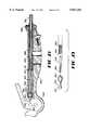
- FIG. 8is a right-side elevational view of a second embodiment of the invention showing a selective lever position locking means in phantom lines and a tool orienting means.
- FIG. 9is an overhead view of the second embodiment of the invention with a partial sectional view taken along lines 9--9 of FIG. 8 showing a selective lever position locking means.
- FIG. 10is right-side exploded detail perspective view of the second embodiment of the present invention showing the tool orienting means.
- FIG. 11is a front end view of the second embodiment of the invention showing the tool orienting means.
- FIG. 12is an exploded right-side perspective view of the selective lever position locking means of the second embodiment of the invention.
- FIG. 13is a detail left-side perspective view of an alternate actuator arm of a third embodiment of the present invention.
- FIG. 14is a front detail sectional view of a fourth embodiment of the present invention taken along the axis of actuator arm rotation showing the rachet and pawl of an alternative selective lever position locking means.
- FIG. 15is a right-side detail elevational view of the fourth embodiment showing the lever position locking means in phantom lines.
- FIG. 16is a right-side partial sectional view of a fifth embodiment of the present invention showing the rachet and pawl of an alternate selective lever position locking means in the unlocked position.
- FIG. 17is a right-side partial sectional view of the fifth embodiment of the present invention showing the rachet and pawl of an alternate selective lever position locking means in the locked position.
- FIG. 18is a detail right-side longitudinal section view of a sixth embodiment of the present invention showing an alternate actuator rod and biasing means configuration.
- FIG. 19is a detail right-side view showing the alternate actuator rod and adapter of the sixth embodiment of the present invention.
- the present inventionprovides a hand-held surgical instrument comprising an improved handle 10 attached to a tool 12 having at least one articulated member 14 thereon.
- the tool 12may be any one of a variety of a conventional surgical tools which has articulating, or moving, parts, such as scissors, hemostats, forceps, suture holders, biopsy retrievers, retractors, staplers and the like.
- the handle 10has an elongated base 20 having a body portion 21, a top surface 22, opposite bottom surface 24, a first side 26 and an opposite second side 28, a proximal end 30 and a distal end 32.
- the handle 10also has an elongated lever 34 having a first surface 36, an opposite second surface 38, a front end 40, a rear end 42 and an actuator arm 44 adjacent the rear end 42.
- the actuator arm 44is adapted to be projected into the body portion 21 of said base 20 at a predetermined point 46.
- the predetermined point 46may vary in position relative to the body portion 21 and the lever 34, depending upon the specific requirements of the surgeon and the tasks to be performed with the tool 12.
- the handle 10also has a means 48 for connecting said actuator arm 44 to said base 20 at the predetermined point 46 to allow said lever 34 to pivot about a linear transverse axis 50 at the predetermined point 46 between a normally open position (shown in FIG. 4) and a closed position (shown in FIG. 5).
- the base 20 and the lever 34are juxtaposed to each other along their length, defining a longitudinal axis.
- the lever 34extends forward along the longitudinal axis from said connecting means 48 toward the distal end 32 of said base 20, such that the first surface 36 of said lever 34 is adjacent to the top surface 22 of said body portion 21.
- the handle 10also has a means for biasing said lever 34 in the normally open position. Additionally, the handle 10 is provided with a means for actuating the articulated member 14 of the tool 12, wherein an actuator rod 56 is pivotally connected at a fixed point 58 on the actuator arm 44 of said lever 34, such that moving said lever 34 from the normally open position (FIG. 4) to the closed position (FIG. 5) causes said fixed point 58 on the actuator arm 44 to be displaced distally 32, thereby moving said actuator rod 56 toward the distal end 32 of the base 20, and causing movement of the articulated member 14.
- the fixed point 58may be positioned in a variety of locations on the actuator arm 44 depending upon the range and force of actuating motion desired and the size and purpose of the tool 12.
- the actuator rod 56further comprises a first end 60 and a second end (not visible), the second end of the rod 56 being connected to the articulated member 14 of the tool 12, and the first end 60 of the rod 56 being connected to the actuator arm 44 at the fixed point 58.
- the rod 56is disposed through the body portion 21 of the base 20, such that movement of the lever 34 from the normally open position (FIG. 4) to the closed position (FIG. 5) causes the first end 60 of the rod 56 to be displaced toward the distal end 32 of the body portion 21 of the base 20, thereby moving the articulated member 14 of the tool 12.
- the first end 60 of the actuator rod 56comprises a pin 64 which is inserted into a complimentary receptacle 66 at the fixed point 58 on the actuator arm 44, thereby pivotally connecting the actuator arm 44 to the actuator rod 56.
- the pin 64 and complimentary receptacle 66are shown to be round in shape, however, a variety of other shapes and configurations which permit a pivotal connection are contemplated.
- the tool 12may further comprise a body member 80 wherein the base 20 defines an opening 82 at the distal end 32 thereof complementary to the shape of a first end 84 of the body member 80 of the tool 12, such that the body portion 21 of the base 20 attachably receives therein the first end 84 of the body member 80, and wherein the articulated member 14 is pivotally attached to an opposite second end 86 of the body member 80.
- the instrumentcan have a hollow elongated tube 88 having the body member 80 and the actuator rod 56 disposed therethrough.
- the slidable actuator rod 56is of the type commonly used in the art for endoscopic instruments, which require movement of a tool.
- the inventionalso contemplates the absence of either the hollow tube 88 or body member 80 such that the actuator rod 56 may not be slidably housed within a hollow elongated tube 88 or body member 80, but rather project directly from the body 21 of the base 20 unhoused.
- a dog point set screw 89serves to secure the elongated tube 88 within the base 20.
- the instrument of the present inventionfurther has a joint 90 for connecting the base 20 of the handle 10 to the actuator arm 44 of the lever 34 at the predetermined point 46.
- the joint 90has a circular hinge socket 92 on the base 20 at the predetermined point 46 which is journalled for motion about the transverse axis, and a hinge barrel 94 on the actuator arm 44 dimensioned to be received within the hinge socket 92.
- journalledit is meant that the socket 92 has been configured, as by machine routing or original dye casting, to receive the hinge barrel 94.
- This joint 90allows the actuator arm 44 to pivot about the transverse axis at the predetermined point when the lever is moved between the normally open position (FIG. 4) and the closed position (FIG. 5).
- the configuration of the base 20 at the joint 90also provides an open-lever stop 95 and a closed lever stop 97, which define a maximum range of motion for the lever 34.
- the inventionmay be provided with an open-lever set screw 98, which is rotated to adjust the range of lever motion.
- a stop-lever set screw(not shown) could also be provided on the closed-lever stop 97.
- the joint 90is shown as a hinged socket, however, a variety of other joints are contemplated for pivotally connecting the base 20 to the lever 34 as would be apparent to one skilled in the art.
- the connecting means 48 of the first embodimentcomprises a continuous bore extending along the transverse axis through the base 20 and through the actuator arm 44.
- the bore on the actuator arm 44has internal threads to receive a fixation screw 104 having a head end 106 and an opposite tail end 108 having threads complimentary to the internal threads, the screw 104 passing through the bore of the base 20 such that the head end 106 of the screw 104 rests within a counterbore 112 on the first side 26 of the base 20.
- the connecting means 48is shown as comprising a threaded fixation screw 104, allowing rotational movement of the actuator arm 44, however, a variety of other connecting means are contemplated by the invention, such as bolts, rivets or other fasteners.
- the connecting meansfor example, can be of the shoulder screw type that prevents clamping of the actuator arm 44 relative to the base 20.
- Alternate single connecting meansare described more fully below with reference to the second embodiment shown in FIGS. 8-12, and the third embodiment shown in FIG. 13.
- the single connecting meansprovide the invention with a greatly increased ease of assembly and disassembly.
- the inventionalso provides a biasing means for biasing the lever 34 in the normally open position, as shown in FIGS. 1-3.
- the biasing means of the first embodiment of the instrumentis a compression coil spring 120 having a pre-selected thickness and which is longitudinally positioned around the actuator rod 56 within the base 20.
- the pre-selected thickness and coiling of the spring 120 wireis intended to vary according to the resistance and sensitivity desired by the surgeon for the particular tool 12.
- the compression spring 120is maintained in compressed elongated alignment within the handle 10 of the instrument such that compression spring 120 urges the lever 34 toward the normally open position.
- the compression spring wire 120has a first end 124 and a second end 122, and the base 20 has a recess therein for receiving the second end 122 of the compression spring wire 120, such that the recess holds the compression spring in alignment with the longitudinal axis against the elongated hollow tube 88.
- the first end 124 of the spring wire 120can be positioned adjacent a pair of adjustable tension nuts 57.
- the second end 122 of the spring wire 120is abutted adjacent a bushing 19. Therefore, in this position, the compression spring 120 urges the lever 34 toward the normally open position.
- the first and second sides 26, 28 of the base 20 and the second surface 38 of the lever 34each are equipped with an ergonomically adapted finger pad 150. These pads 150 assist the surgeon in maintaining a comfortable and secure grip on the instrument.
- the ergonomically adapted finger pads 150are adapted for holding between the operator's thumb and fingers.
- the first and second sides 26, 28have opposing concave curvatures corresponding to the shape of human digits. Furthermore, the bottom of the sides 26, 28 converge toward each other at the bottom surface 24 such that the top surface 22 is wider than the bottom surface 24.
- the two sides 26, 28 of the base 20can each terminate in support feet 154 which allow the instrument to stand independently.
- the base 20can further comprise a counterweight 160 positioned within the proximal end 30 of the base 20 to balance the instrument at a second predetermined point (not shown).
- the second predetermined pointwill vary depending upon the combination of the mass of the counterweight 160 and the mass of the surgical tool 12. It is contemplated that the second predetermined point could be adjusted in the surgeon's hand by rotating the counterweight 160, thereby changing the distance between the counterweight 160 and the transverse axis 50.
- the counterweight 160may be attached to the base 20 by means of an elongated threaded rod (not shown) on the base 20 which is received into a complimentarily threaded opening in the counterweight 160. By rotating the counterweight 160 the distance between the counterweight 160 and the transverse axis 50 changes, and thus also the second predetermined point.
- the inventionprovides a closed lever position locking means of the first embodiment.
- a transverse notch 45 in the actuator arm 44which is in alignment with a bore 23 through the base 20 when the lever 34 is in the closed position, and a locking pin 25 having a first portion 27 and a second portion 29 movable between an unlocked position and a locked position such that when the locking pin 25 is in the unlocked position (FIG. 7) the first portion 27 permits the actuator rod 56 to move distally or proximally, and when the locking pin 25 is in the locked position (FIG. 7A) in communication with the transverse notch 45 in the actuator arm 44, the second portion 29 prevents the actuator rod 56 from being displaced.
- the locking pin 25is maintained in position within the bore 23 by an internal spring 31.
- the inventioncan also have a flush port 18 in the bottom surface 24 of the base 20, which is in communication with the actuator rod 56, body member 80 and hollow elongated tube 88.
- This flush port 18permits rinsing the internal compartments of the instrument to remove debris, such as coagulated blood and tissues.
- a bushing seal 19directs the flow of rinsing solution distally past the actuator rod 56.
- the inventionalso contemplates that the distal end 232 of the base 220 may be adapted for selective rotation along an axis in alignment with the longitudinal axis of the base 220, thereby allowing the surgical tool 212 to selectively rotate.
- a rotatable tool positioning collar 281can be mounted on the body member 280 of the tool 212 adjacent the opening of the body portion 282 of the base 220.
- the collar 281has a plurality of radial detents 283 thereon.
- a set screw 291is positioned through a receptacle on the collar 281 to affix the collar 281 to the body member 280 of the tool 212, such that rotation of the collar 281 causes rotation of the body member 280 and the tool 212.
- a set pin 285 of a size corresponding to the detents 283is disposed adjacent the distal end 232 of the body portion 221 of the base 220 to be in selective communication with the detents 283 of the rotatable tool positioning collar 281.
- the set pin 285is spring-loaded from the rear and is connected to a release tab 287 journalled through an elongated slot.
- the set pin 285may be moved out of communication with the detents 283 to rotate the collar 281 by pulling the release tab 287 rearward against the spring-load.
- the set pin 285has a bullet-shaped tip 275 corresponding to the tapered shape of the detents 283 such that more secure positioning of the collar 281 can be achieved.
- the actuator rod 256may be pivotally connected to the actuator arm 244 wherein the first end 260 of the actuator rod 256 comprises a rearward end 268, and further comprising a barrel-shaped actuator cuff 270 having a first end 271 with a complimentarily internal opening for receiving the rearward end 268 of the actuator rod 256, which is maintained in place by the "C" clip 262. Additional “C” clip 267 can be provided to maintain the spring (not shown) in place around the actuator rod 256.
- the actuator rod 256has a second end 274 comprising a pin 276 which is inserted into a complimentary receptacle 278 on the actuator arm 244. This second embodiment is preferred with the rotatable tool orienting means feature described above to prevent unthreading of the actuator rod 256.
- the second embodimentprovides one means for securing the handle lever 234 at selected points throughout a range of motion defined between and including the open position and the closed position.
- the securing meanscan be a friction clutch 233 having a first portion 235 rotatably disposed through a bore 237 in the base 220 in selective communication with the actuator arm 244 and adapted for movement between a locked position and an unlocked position, such that when the clutch 233 is in the locked position, the first portion 235 increases friction against the actuator arm 244 preventing movement of the lever 234, and when the clutch 233 is in the unlocked position the first portion 235 decreases friction against the actuator arm 244, permitting movement of the lever 234.
- This embodimentalso has a single means for connecting the clutch 233, the actuator arm 244 and the base 220 together, shown as a threaded fixation screw 248.
- FIG. 13shows an alternate actuating means of the third embodiment of the present invention.
- the actuator rod 356has a rounded, or beaded, tip 361 on the first, or proximal, end 360 thereof The beaded tip 361 is received within a corresponding slot 359 on the actuator arm 344. The end of the slot 359 corresponding to the beaded tip 361 is larger than the rest of the slot 359 due to a narrowing wall portion 357 on the actuator arm 344.
- the actuator rod 356may be removed from the left-side only when the lever 334 is in the fully closed position.
- the actuator rod 356serves to maintain the actuator arm 344 in pivotal connection to the base (not shown) at the first predetermined point (not shown), without the need for additional fastening means. Therefore, this third embodiment also provides an alternative single connecting means.
- FIGS. 14 and 15show the fourth embodiment having a means for securing the handle lever 434 at selected points throughout a range of motion.
- the securing meansis shown as a rachet system having a rachet plate 402 having a toothed surface 403 thereon mounted on the actuator arm 444, and a pawl arm 404 having a pawl tooth 408 complementary to the rachet plate teeth 403.
- the pawl arm 404has a notch 406 therein, and is pivotally mounted upon the base 420, such that the pawl tooth 408 is capable of selectively engaging the toothed surface 403 of the rachet plate 402 throughout the range of motion of the lever 434.
- a rachet lever 407is disposed though the base 420 in communication with the notch 406 on the pawl arm 404, the rachet lever 407 being pivotally mounted within the base 420 such that the rachet lever 407 is moveable between a locked position, wherein the pawl tooth 408 is in engagement with the rachet plate 402, and an unlocked position, wherein the pawl tooth 408 is disengaged from the rachet plate 402.
- the pawl tooth 408is releasably biased into engagement with the rachet plate 402 by a compression spring 411 disposed between the pawl arm 404 and the actuator arm 444.
- FIGS. 16 and 17show a fifth embodiment of the present invention having a means for securing the lever 534 at selected point throughout a range of motion.
- the securing meansis shown as an alternative rachet system having a rachet plate 502 having a toothed surface 503 thereon mounted on the base 520, and a pawl arm 504 having a pawl tooth 508 complementary to the rachet plate teeth 503 which is pivotally mounted upon the lever 534 such that the pawl tooth 508 is capable of selectively engaging the toothed surface 503 of the rachet plate 502 throughout the range of motion of the lever.
- a pawl lever 507is pivotally mounted on the lever 534 in communication with the pawl arm 504 such that the pawl lever 507 is moveable between a biased position (FIG. 17), wherein the pawl tooth 508 is in engagement with the rachet plate 502, and an unlocked position (FIG. 16), wherein the pawl tooth 508 is disengaged from the rachet plate 502.
- the pawl tooth 508is releasably biased into engagement with the rachet plate 502 by a compression spring 511 disposed between the handle lever 534 and the pawl lever 507.
- FIGS. 18 and 19show a sixth embodiment of the present invention.
- the first, or proximal, end 660 of the actuator rod 656is fitted with an adapter 663 with a beaded tip 661.
- the beaded tip 661is rotatably received in a corresponding slot 659 on the actuator arm 644.
- the opposite, or distal, end 662 of the adapter 661has internal threads corresponding to threads on the first end 660 of the actuator rod 656, however, a variety of constructions are possible.
- the adapter 663has a larger diameter at the distal end 662 than the actuator rod 656, such that the first end 624 of the compression spring 652 lever biasing means is maintained adjacent the distal end 662 of the adapter 663 and in longitudinal alignment with the longitudinal axis, without the use of tensioning nuts used in the first embodiment.
- the second end 622 of the compression spring 652is abutted adjacent the bushing seal 619.
- This embodimentalso shows that the proximal end of the body member 680 of the tool 612 can be flared to abut against the hollow elongated tube 688. In addition to the set screw 689 against the hollow tube 688, the flared proximal end of the body member 680 of the tool 612 serves to maintain the tool 612 in position within the handle base 620 during normal use and rotation.
- the present inventionmay be utilized on any suitable surgical instrument with an articulated member on the tool including, but not limited to, conventional hand-held surgical instruments and minimally invasive surgical instruments, such as endoscopic and arthroscopic instruments.
- the instruments of the present inventionmay be constructed from any suitable material, such as metal or plastic. Examples of metals include stainless steel, aluminum and titanium. Examples of plastics include acetal, polycarbonate, ABS, and the like.
Landscapes
- Health & Medical Sciences (AREA)
- Surgery (AREA)
- Life Sciences & Earth Sciences (AREA)
- Biomedical Technology (AREA)
- Nuclear Medicine, Radiotherapy & Molecular Imaging (AREA)
- Engineering & Computer Science (AREA)
- Ophthalmology & Optometry (AREA)
- Heart & Thoracic Surgery (AREA)
- Medical Informatics (AREA)
- Molecular Biology (AREA)
- Animal Behavior & Ethology (AREA)
- General Health & Medical Sciences (AREA)
- Public Health (AREA)
- Veterinary Medicine (AREA)
- Surgical Instruments (AREA)
Abstract
Description
Claims (23)
Priority Applications (1)
| Application Number | Priority Date | Filing Date | Title |
|---|---|---|---|
| US08/914,525US5827263A (en) | 1994-07-21 | 1997-08-19 | Surgical instrument handle |
Applications Claiming Priority (3)
| Application Number | Priority Date | Filing Date | Title |
|---|---|---|---|
| US08/278,632US5470328A (en) | 1994-07-21 | 1994-07-21 | Surgical instrument handle and actuator means |
| US54047295A | 1995-10-10 | 1995-10-10 | |
| US08/914,525US5827263A (en) | 1994-07-21 | 1997-08-19 | Surgical instrument handle |
Related Parent Applications (1)
| Application Number | Title | Priority Date | Filing Date |
|---|---|---|---|
| US54047295AContinuation | 1994-07-21 | 1995-10-10 |
Publications (1)
| Publication Number | Publication Date |
|---|---|
| US5827263Atrue US5827263A (en) | 1998-10-27 |
Family
ID=26959200
Family Applications (1)
| Application Number | Title | Priority Date | Filing Date |
|---|---|---|---|
| US08/914,525Expired - LifetimeUS5827263A (en) | 1994-07-21 | 1997-08-19 | Surgical instrument handle |
Country Status (1)
| Country | Link |
|---|---|
| US (1) | US5827263A (en) |
Cited By (18)
| Publication number | Priority date | Publication date | Assignee | Title |
|---|---|---|---|---|
| WO2002069815A1 (en)* | 2001-03-01 | 2002-09-12 | Heinrich Widmann | Surgical instrument |
| US20030167640A1 (en)* | 2002-03-05 | 2003-09-11 | Ames True Temper, Inc. | Pruners for cutting vegetation |
| US20030212435A1 (en)* | 2002-03-26 | 2003-11-13 | Adam Gold | Handleless clamping device |
| US6944914B2 (en)* | 2001-10-24 | 2005-09-20 | Tillim Stephen L | Handle and forceps/tweezers and method and apparatus for designing the like |
| US6988295B2 (en) | 2001-10-24 | 2006-01-24 | Tillim Stephen L | Handle/grip and method for designing the like |
| US7010835B2 (en) | 2001-10-24 | 2006-03-14 | Tillim Stephen L | Parallel handle system and method for designing a parallel handle system |
| US7131973B2 (en) | 2002-05-16 | 2006-11-07 | Boston Scientific Scimed, Inc. | Bone anchor implantation device |
| US20070299469A1 (en)* | 2006-06-26 | 2007-12-27 | David Carpenter | Surgical device |
| US20080195129A1 (en)* | 2007-02-13 | 2008-08-14 | Weber Robert M | Mid-point lock suture cutter |
| US20120101518A1 (en)* | 2010-10-25 | 2012-04-26 | West Virginia University | DePond clamp |
| US9113939B2 (en) | 2009-10-09 | 2015-08-25 | Applied Medical Resources Corporation | Single port instruments |
| US9649109B2 (en) | 2013-03-14 | 2017-05-16 | C.R. Bard, Inc. | Surgical instrument with an actuation lockout |
| US9901335B2 (en)* | 2014-07-10 | 2018-02-27 | Maxwell Choongwon Park | Method and apparatus for securing soft tissue to bone |
| US10159471B2 (en) | 2015-05-13 | 2018-12-25 | C.R. Bard, Inc. | Actuation lockout for a surgical instrument |
| US10405858B2 (en) | 2015-06-30 | 2019-09-10 | C.R. Bard, Inc. | Actuation lockout for a surgical instrument |
| US10925657B2 (en) | 2014-11-19 | 2021-02-23 | Stryker Corporation | Surgical wire driver capable of automatically adjusting for the diameter of the wire or pin being driven |
| CN112955084A (en)* | 2018-10-22 | 2021-06-11 | 奥林巴斯株式会社 | Treatment tool |
| US11478265B2 (en)* | 2019-01-23 | 2022-10-25 | Scanlan International, Inc. | Surgical instrument |
Citations (23)
| Publication number | Priority date | Publication date | Assignee | Title |
|---|---|---|---|---|
| US2898916A (en)* | 1952-04-12 | 1959-08-11 | Kammer Karl | Devices for the gripping and ligaturing of the ends of tubular vessels |
| US4248233A (en)* | 1974-11-19 | 1981-02-03 | Zeppelin Dieter Von | Forceps |
| WO1981003122A1 (en)* | 1980-05-02 | 1981-11-12 | Acufex Microsurgical Inc | Microsurgical scissors |
| US4590936A (en)* | 1983-02-02 | 1986-05-27 | Ewald Hensler | Microsurgical instrument |
| US4598711A (en)* | 1984-08-09 | 1986-07-08 | American Cyanamid Company | Surgical instrument |
| US4644651A (en)* | 1984-03-19 | 1987-02-24 | Jacobsen Research Corp. | Instrument for gripping or cutting |
| US4777948A (en)* | 1984-01-16 | 1988-10-18 | Wright David W | Surgical tool |
| US4950273A (en)* | 1987-10-26 | 1990-08-21 | Briggs Jeffrey M | Cable action instrument |
| US4957500A (en)* | 1988-10-27 | 1990-09-18 | Montefiore Hospital Association Of Western Pennsylvania | Normally closed clamp |
| US5009661A (en)* | 1989-04-24 | 1991-04-23 | Michelson Gary K | Protective mechanism for surgical rongeurs |
| US5195505A (en)* | 1990-12-27 | 1993-03-23 | United States Surgical Corporation | Surgical retractor |
| US5199419A (en)* | 1991-08-05 | 1993-04-06 | United States Surgical Corporation | Surgical retractor |
| US5250073A (en)* | 1992-06-10 | 1993-10-05 | Cordis Corporation | Torqueable and formable biopsy forceps |
| US5273519A (en)* | 1990-11-02 | 1993-12-28 | Tibor Koros | Bongeur surgical instrument |
| US5304203A (en)* | 1992-10-20 | 1994-04-19 | Numed Technologies, Inc. | Tissue extracting forceps for laparoscopic surgery |
| US5330502A (en)* | 1992-10-09 | 1994-07-19 | Ethicon, Inc. | Rotational endoscopic mechanism with jointed drive mechanism |
| US5336238A (en)* | 1993-07-19 | 1994-08-09 | Birtcher Medical Systems, Inc. | Surgical instrument capable of disassembly |
| US5342391A (en)* | 1992-10-06 | 1994-08-30 | Linvatec Corporation | Cleanable endoscopic surgical instrument |
| US5466243A (en)* | 1994-02-17 | 1995-11-14 | Arthrex, Inc. | Method and apparatus for installing a suture anchor through a hollow cannulated grasper |
| US5470328A (en)* | 1994-07-21 | 1995-11-28 | Snowden-Pencer, Inc. | Surgical instrument handle and actuator means |
| US5498256A (en)* | 1993-05-28 | 1996-03-12 | Snowden-Pencer, Inc. | Surgical instrument handle |
| US5624431A (en)* | 1991-10-03 | 1997-04-29 | United States Surgical Corporation | Handle for manipulating a laparoscopic tool |
| US5665105A (en)* | 1996-03-20 | 1997-09-09 | Snowden Pencer/Genzyme Corporation | Radially adjustable surgical instrument for heart surgery |
- 1997
- 1997-08-19USUS08/914,525patent/US5827263A/ennot_activeExpired - Lifetime
Patent Citations (23)
| Publication number | Priority date | Publication date | Assignee | Title |
|---|---|---|---|---|
| US2898916A (en)* | 1952-04-12 | 1959-08-11 | Kammer Karl | Devices for the gripping and ligaturing of the ends of tubular vessels |
| US4248233A (en)* | 1974-11-19 | 1981-02-03 | Zeppelin Dieter Von | Forceps |
| WO1981003122A1 (en)* | 1980-05-02 | 1981-11-12 | Acufex Microsurgical Inc | Microsurgical scissors |
| US4590936A (en)* | 1983-02-02 | 1986-05-27 | Ewald Hensler | Microsurgical instrument |
| US4777948A (en)* | 1984-01-16 | 1988-10-18 | Wright David W | Surgical tool |
| US4644651A (en)* | 1984-03-19 | 1987-02-24 | Jacobsen Research Corp. | Instrument for gripping or cutting |
| US4598711A (en)* | 1984-08-09 | 1986-07-08 | American Cyanamid Company | Surgical instrument |
| US4950273A (en)* | 1987-10-26 | 1990-08-21 | Briggs Jeffrey M | Cable action instrument |
| US4957500A (en)* | 1988-10-27 | 1990-09-18 | Montefiore Hospital Association Of Western Pennsylvania | Normally closed clamp |
| US5009661A (en)* | 1989-04-24 | 1991-04-23 | Michelson Gary K | Protective mechanism for surgical rongeurs |
| US5273519A (en)* | 1990-11-02 | 1993-12-28 | Tibor Koros | Bongeur surgical instrument |
| US5195505A (en)* | 1990-12-27 | 1993-03-23 | United States Surgical Corporation | Surgical retractor |
| US5199419A (en)* | 1991-08-05 | 1993-04-06 | United States Surgical Corporation | Surgical retractor |
| US5624431A (en)* | 1991-10-03 | 1997-04-29 | United States Surgical Corporation | Handle for manipulating a laparoscopic tool |
| US5250073A (en)* | 1992-06-10 | 1993-10-05 | Cordis Corporation | Torqueable and formable biopsy forceps |
| US5342391A (en)* | 1992-10-06 | 1994-08-30 | Linvatec Corporation | Cleanable endoscopic surgical instrument |
| US5330502A (en)* | 1992-10-09 | 1994-07-19 | Ethicon, Inc. | Rotational endoscopic mechanism with jointed drive mechanism |
| US5304203A (en)* | 1992-10-20 | 1994-04-19 | Numed Technologies, Inc. | Tissue extracting forceps for laparoscopic surgery |
| US5498256A (en)* | 1993-05-28 | 1996-03-12 | Snowden-Pencer, Inc. | Surgical instrument handle |
| US5336238A (en)* | 1993-07-19 | 1994-08-09 | Birtcher Medical Systems, Inc. | Surgical instrument capable of disassembly |
| US5466243A (en)* | 1994-02-17 | 1995-11-14 | Arthrex, Inc. | Method and apparatus for installing a suture anchor through a hollow cannulated grasper |
| US5470328A (en)* | 1994-07-21 | 1995-11-28 | Snowden-Pencer, Inc. | Surgical instrument handle and actuator means |
| US5665105A (en)* | 1996-03-20 | 1997-09-09 | Snowden Pencer/Genzyme Corporation | Radially adjustable surgical instrument for heart surgery |
Non-Patent Citations (16)
| Title |
|---|
| Excerp from article on Laproscopic Suturing System, Karl Storz, Endoscopy American, Inc. (date unknown).* |
| Excerp from article on Laproscopic Suturing System, Karl Storz, Endoscopy-American, Inc. (date unknown). |
| Photocopy of actual Ethicon (MIC 608) instrument handle (date unknown).* |
| Promotional Literature (catalog) Medicon instrumente, (date unknown).* |
| Promotional Literature, Access Surgical International, Inc. (Sep. 1992).* |
| Promotional Literature, AESCULAP ProMis Line Pen handle Psalmon endoscopic handle (Sep. 1994).* |
| Promotional Literature, AESCULAP® ProMis Line® Pen-handle-Psalmon endoscopic-handle (Sep. 1994). |
| Promotional Literature, Aslan Medical Technologies (date unknown).* |
| Promotional Literature, B. Braun Dexon GmbH (date unknown).* |
| Promotional Literature, B. Braun-Dexon GmbH (date unknown). |
| Promotional Literature, Endotec Endoscopic Technologies, Inc. (1993).* |
| Promotional Literature, Jarit, Inc. Mar. (1992).* |
| Promotional Literature, Karl Storz GmbH & Co. Szabo Berci Needle Drivers (1991).* |
| Promotional Literature, Karl Storz GmbH & Co. Szabo-Berci Needle Drivers (1991). |
| Promotional Literature, Snowden Pencer (1990).* |
| Promotional Literature, Snowden-Pencer (1990). |
Cited By (48)
| Publication number | Priority date | Publication date | Assignee | Title |
|---|---|---|---|---|
| WO2002069815A1 (en)* | 2001-03-01 | 2002-09-12 | Heinrich Widmann | Surgical instrument |
| US7506409B2 (en) | 2001-10-24 | 2009-03-24 | Tillim Stephen L | Handle/grip and method for designing the like |
| US6944914B2 (en)* | 2001-10-24 | 2005-09-20 | Tillim Stephen L | Handle and forceps/tweezers and method and apparatus for designing the like |
| US6988295B2 (en) | 2001-10-24 | 2006-01-24 | Tillim Stephen L | Handle/grip and method for designing the like |
| US7010835B2 (en) | 2001-10-24 | 2006-03-14 | Tillim Stephen L | Parallel handle system and method for designing a parallel handle system |
| US20030167640A1 (en)* | 2002-03-05 | 2003-09-11 | Ames True Temper, Inc. | Pruners for cutting vegetation |
| US9782174B2 (en) | 2002-03-26 | 2017-10-10 | Intuitive Surgical Operations, Inc. | Handleless clamping device |
| US8361108B2 (en) | 2002-03-26 | 2013-01-29 | Intuitive Surgical Operations, Inc. | Handleless clamping device |
| US10702272B2 (en) | 2002-03-26 | 2020-07-07 | Intuitive Surgical Operations, Inc. | Handleless clamping device |
| US20090093828A1 (en)* | 2002-03-26 | 2009-04-09 | Novare Surgical Systems, Inc. | Handleless clamping device |
| US20090093842A1 (en)* | 2002-03-26 | 2009-04-09 | Novare Surgical Systems, Inc. | Handleless clamping device |
| US20090093841A1 (en)* | 2002-03-26 | 2009-04-09 | Novare Surgical Systems, Inc. | Handleless clamping device |
| US7588585B2 (en) | 2002-03-26 | 2009-09-15 | Novare Surgical Systems, Inc. | Handleless clamping device |
| US11439394B2 (en) | 2002-03-26 | 2022-09-13 | Intuitive Surgical Operations, Inc. | Handleless clamping device |
| US20030212435A1 (en)* | 2002-03-26 | 2003-11-13 | Adam Gold | Handleless clamping device |
| US8506590B2 (en) | 2002-03-26 | 2013-08-13 | Intuitive Surgical Operations, Inc. | Handleless clamping device |
| US7131973B2 (en) | 2002-05-16 | 2006-11-07 | Boston Scientific Scimed, Inc. | Bone anchor implantation device |
| US7674269B2 (en) | 2002-05-16 | 2010-03-09 | Boston Scientific Scimed, Inc. | Bone anchor implantation device |
| US20070299469A1 (en)* | 2006-06-26 | 2007-12-27 | David Carpenter | Surgical device |
| US7846177B2 (en) | 2006-06-26 | 2010-12-07 | Carefusion 2200, Inc. | Surgical device |
| US8591523B2 (en) | 2007-02-13 | 2013-11-26 | Arthrex, Inc. | Mid-point lock suture cutter |
| EP1958572A3 (en)* | 2007-02-13 | 2009-12-30 | Arthrex, Inc. | Mid-point lock suture cutter |
| US20080195129A1 (en)* | 2007-02-13 | 2008-08-14 | Weber Robert M | Mid-point lock suture cutter |
| US10420576B2 (en)* | 2009-10-09 | 2019-09-24 | Applied Medical Resources Corporation | Single port instruments |
| US9113939B2 (en) | 2009-10-09 | 2015-08-25 | Applied Medical Resources Corporation | Single port instruments |
| US20150359552A1 (en)* | 2009-10-09 | 2015-12-17 | Applied Medical Resources Corporation | Single port instruments |
| US11622783B2 (en) | 2009-10-09 | 2023-04-11 | Applied Medical Resources Corporation | Single port instruments |
| US20120101518A1 (en)* | 2010-10-25 | 2012-04-26 | West Virginia University | DePond clamp |
| US10653419B2 (en) | 2013-03-14 | 2020-05-19 | C.R. Bard, Inc. | Surgical instrument with an actuation lockout |
| US12161334B2 (en) | 2013-03-14 | 2024-12-10 | C.R. Bard, Inc. | Surgical instrument with an actuation lockout |
| US9649109B2 (en) | 2013-03-14 | 2017-05-16 | C.R. Bard, Inc. | Surgical instrument with an actuation lockout |
| US11457919B2 (en) | 2013-03-14 | 2022-10-04 | C.R. Bard, Inc. | Surgical instrument with an actuation lockout |
| US9901335B2 (en)* | 2014-07-10 | 2018-02-27 | Maxwell Choongwon Park | Method and apparatus for securing soft tissue to bone |
| US11672582B2 (en) | 2014-11-19 | 2023-06-13 | Stryker Corporation | Surgical wire driver capable of automatically adjusting for the diameter of the wire or pin being driven |
| US10925657B2 (en) | 2014-11-19 | 2021-02-23 | Stryker Corporation | Surgical wire driver capable of automatically adjusting for the diameter of the wire or pin being driven |
| US12048424B2 (en) | 2015-05-13 | 2024-07-30 | C.R. Bard, Inc. | Actuation lockout for a surgical instrument |
| US11389143B2 (en) | 2015-05-13 | 2022-07-19 | C.R. Bard, Inc. | Actuation lockout for a surgical instrument |
| US10772613B2 (en) | 2015-05-13 | 2020-09-15 | C.R. Bard, Inc. | Actuation lockout for a surgical instrument |
| US10159471B2 (en) | 2015-05-13 | 2018-12-25 | C.R. Bard, Inc. | Actuation lockout for a surgical instrument |
| US11147550B2 (en) | 2015-06-30 | 2021-10-19 | C.R. Bard, Inc. | Actuation lockout for a surgical instrument |
| US11751868B2 (en) | 2015-06-30 | 2023-09-12 | C.R. Bard, Inc. | Actuation lockout for a surgical instrument |
| US10405858B2 (en) | 2015-06-30 | 2019-09-10 | C.R. Bard, Inc. | Actuation lockout for a surgical instrument |
| US12089839B2 (en) | 2015-06-30 | 2024-09-17 | C.R. Bard, Inc. | Actuation lockout for a surgical instrument |
| US20210228265A1 (en)* | 2018-10-22 | 2021-07-29 | Olympus Corporation | Treatment tool |
| CN112955084A (en)* | 2018-10-22 | 2021-06-11 | 奥林巴斯株式会社 | Treatment tool |
| CN112955084B (en)* | 2018-10-22 | 2024-09-17 | 奥林巴斯株式会社 | Disposal equipment |
| US12108976B2 (en)* | 2018-10-22 | 2024-10-08 | Olympus Corporation | Treatment tool |
| US11478265B2 (en)* | 2019-01-23 | 2022-10-25 | Scanlan International, Inc. | Surgical instrument |
Similar Documents
| Publication | Publication Date | Title |
|---|---|---|
| US5665105A (en) | Radially adjustable surgical instrument for heart surgery | |
| US5797956A (en) | Surgical instrument handle and actuator means for heart surgery | |
| EP0695533B1 (en) | Improved surgical instrument handle with actuator means | |
| US5827263A (en) | Surgical instrument handle | |
| US5498256A (en) | Surgical instrument handle | |
| US6540737B2 (en) | Handle for a medical instrument | |
| US5893873A (en) | Surgical instrument having a handle with a removable, rotatable tip | |
| US4753235A (en) | Forceps-type surgical instrument | |
| US6436122B1 (en) | Handle for a medical instrument | |
| US8585734B2 (en) | Ergonomic handle and articulating laparoscopic tool | |
| US5146810A (en) | Grip system for hand tools and instruments | |
| US6129740A (en) | Instrument handle design | |
| US5630831A (en) | Fingerlike medical instruments for use in laparoscopic procedures | |
| US6500188B2 (en) | Ultrasonic surgical instrument with finger actuator | |
| US5211655A (en) | Multiple use forceps for endoscopy | |
| JP4364472B2 (en) | Laparoscopic forceps handle | |
| US4613179A (en) | Hand-held gripping device with improved support for handicapped persons having limited finger function or wrist strength | |
| US7758608B2 (en) | Enhanced dexterity surgical hand piece | |
| US20100191225A1 (en) | Surgical instrument handle | |
| JPS59137043A (en) | Surgical instrument | |
| US5046381A (en) | Grip system for hand tools and instruments | |
| US6299624B1 (en) | Handle for a medical instrument | |
| US5405353A (en) | Microsurgical needle holder | |
| JP2002253561A (en) | Forceps | |
| EP2471473A1 (en) | Apparatus for laparoscopic surgery |
Legal Events
| Date | Code | Title | Description |
|---|---|---|---|
| AS | Assignment | Owner name:GENZYME CORPORATION, MASSACHUSETTS Free format text:ASSIGNMENT OF ASSIGNORS INTEREST;ASSIGNORS:FURNISH, GREGORY R.;HIPPS, W. MICHAEL;REEL/FRAME:008785/0773;SIGNING DATES FROM 19971008 TO 19971031 | |
| STCF | Information on status: patent grant | Free format text:PATENTED CASE | |
| FPAY | Fee payment | Year of fee payment:4 | |
| AS | Assignment | Owner name:SNOWDEN PENCER, INC., GEORGIA Free format text:ASSIGNMENT OF ASSIGNORS INTEREST;ASSIGNOR:GENZYME, CORPORATION;REEL/FRAME:013998/0554 Effective date:20011121 | |
| FPAY | Fee payment | Year of fee payment:8 | |
| FEPP | Fee payment procedure | Free format text:PAYOR NUMBER ASSIGNED (ORIGINAL EVENT CODE: ASPN); ENTITY STATUS OF PATENT OWNER: LARGE ENTITY Free format text:PAYER NUMBER DE-ASSIGNED (ORIGINAL EVENT CODE: RMPN); ENTITY STATUS OF PATENT OWNER: LARGE ENTITY | |
| FPAY | Fee payment | Year of fee payment:12 | |
| AS | Assignment | Owner name:ALLEGIANCE CORPORATION, ILLINOIS Free format text:MERGER;ASSIGNOR:SNOWDEN-PENCER, INC.;REEL/FRAME:029111/0663 Effective date:20040628 | |
| AS | Assignment | Owner name:CARDINAL HEALTH CMP 200, INC, CALIFORNIA Free format text:ASSIGNMENT OF ASSIGNORS INTEREST;ASSIGNOR:ALLEGIANCE CORPORATION;REEL/FRAME:029124/0517 Effective date:20090817 | |
| AS | Assignment | Owner name:CAREFUSION 2200, INC., CALIFORNIA Free format text:CHANGE OF NAME;ASSIGNOR:CARDINAL HEALTH CMP 200, INC.;REEL/FRAME:029132/0904 Effective date:20090729 |