US5827082A - Hinged device - Google Patents
Hinged deviceDownload PDFInfo
- Publication number
- US5827082A US5827082AUS08/763,931US76393196AUS5827082AUS 5827082 AUS5827082 AUS 5827082AUS 76393196 AUS76393196 AUS 76393196AUS 5827082 AUS5827082 AUS 5827082A
- Authority
- US
- United States
- Prior art keywords
- connecting piece
- hinges
- pivoting
- base part
- pair
- Prior art date
- Legal status (The legal status is an assumption and is not a legal conclusion. Google has not performed a legal analysis and makes no representation as to the accuracy of the status listed.)
- Expired - Lifetime
Links
Images


Classifications
- G—PHYSICS
- G06—COMPUTING OR CALCULATING; COUNTING
- G06F—ELECTRIC DIGITAL DATA PROCESSING
- G06F1/00—Details not covered by groups G06F3/00 - G06F13/00 and G06F21/00
- G06F1/16—Constructional details or arrangements
- G06F1/1613—Constructional details or arrangements for portable computers
- G06F1/1615—Constructional details or arrangements for portable computers with several enclosures having relative motions, each enclosure supporting at least one I/O or computing function
- G06F1/1616—Constructional details or arrangements for portable computers with several enclosures having relative motions, each enclosure supporting at least one I/O or computing function with folding flat displays, e.g. laptop computers or notebooks having a clamshell configuration, with body parts pivoting to an open position around an axis parallel to the plane they define in closed position
- G—PHYSICS
- G06—COMPUTING OR CALCULATING; COUNTING
- G06F—ELECTRIC DIGITAL DATA PROCESSING
- G06F1/00—Details not covered by groups G06F3/00 - G06F13/00 and G06F21/00
- G06F1/16—Constructional details or arrangements
- G06F1/1613—Constructional details or arrangements for portable computers
- G06F1/1633—Constructional details or arrangements of portable computers not specific to the type of enclosures covered by groups G06F1/1615 - G06F1/1626
- G06F1/1675—Miscellaneous details related to the relative movement between the different enclosures or enclosure parts
- G06F1/1681—Details related solely to hinges
- G—PHYSICS
- G06—COMPUTING OR CALCULATING; COUNTING
- G06F—ELECTRIC DIGITAL DATA PROCESSING
- G06F1/00—Details not covered by groups G06F3/00 - G06F13/00 and G06F21/00
- G06F1/16—Constructional details or arrangements
- G06F1/1613—Constructional details or arrangements for portable computers
- G06F1/1633—Constructional details or arrangements of portable computers not specific to the type of enclosures covered by groups G06F1/1615 - G06F1/1626
- G06F1/1675—Miscellaneous details related to the relative movement between the different enclosures or enclosure parts
- G06F1/1683—Miscellaneous details related to the relative movement between the different enclosures or enclosure parts for the transmission of signal or power between the different housings, e.g. details of wired or wireless communication, passage of cabling
- H—ELECTRICITY
- H01—ELECTRIC ELEMENTS
- H01R—ELECTRICALLY-CONDUCTIVE CONNECTIONS; STRUCTURAL ASSOCIATIONS OF A PLURALITY OF MUTUALLY-INSULATED ELECTRICAL CONNECTING ELEMENTS; COUPLING DEVICES; CURRENT COLLECTORS
- H01R35/00—Flexible or turnable line connectors, i.e. the rotation angle being limited
- H01R35/02—Flexible line connectors without frictional contact members
Definitions
- the inventionis related to a device comprising a base part, a pivoting part, and a hinge structure comprising a first pair of hinges and a second pair of hinges, the hinge structure being used to pivotally mount the pivoting part on the base part; and an electric connection means between the base part and the pivoting part.
- U.S. Pat. publication 4,571,456discloses a portable computer according to the appended FIGS. 4a and 4b, comprising base part 22, display unit 23, and cable 24 between the base part and the display unit.
- Display unit 23is pivotally mounted on base part 22 by hinge structure 25.
- Cable 24travels through the hinge in the direction of the hinge line, whereby, when the display unit is opened and closed, torsion is exerted on the cable to the extent of the spread angle of the display unit, causing stress on the cable.
- This structureis only applicable for round cables but not for, e.g., flat cables which require a larger space.
- Another disadvantage of this known deviceis that it is difficult to disassemble and reassemble for maintenance.
- Publication WO-90/10818discloses a portable computer comprising a base part and a display unit pivotally mounted on the base part, and a flat cable between the base part and the display unit.
- the specially built flat cabletravels inside a split pivot pin in the direction of the hinge line.
- the flat cableAt the entry point of the flat cable, there is provided an extra length of loose cable which enables the cable to wind around the pivot pin when the hinge is pivoted.
- Organizer-type devicesemploy a hinge structure in which the input opening of the cables is implemented perpendicular to the hinge line, whereby the bending radius of the cables are small and the bending angle is as large as the spread angle of the device. This may cause stress on the cables, and furthermore, the cables must be provided with an extra length of loose cable.
- the object of the inventionis to provide a device comprising a hinge structure for cable input openings which avoids the disadvantages of the above-mentioned known solutions, and which is simple in structure and easy to assemble and disassemble.
- the object of the inventionis particularly to provide a hinge structure that is well-adapted for input openings of different types of cables, including flat cables, and in which the stress exerted on the cables is small.
- the inventioncomprises a device comprising a base part, a pivoting part, and a hinge structure comprising a first pair of hinges and a second pair of hinges, the hinge structure being used to pivotally mount the pivoting part on the base part, and electric connection means between the base part and the pivoting part, the device being characterised in that a connecting piece is provided between the first pair of hinges and the second pair of hinges, through which the electric connection means are taken and which is adapted to partly pivot along with the pivoting part, the swing angle ⁇ of the connecting piece being smaller than the swing angle ⁇ of the hinge, i.e., the spread angle of the device.
- the said connecting piececomprises a member that allows the connecting piece to partly swing along with the pivoting part.
- This membermay comprise a projecting part on the outer surface of the connecting piece, whereby the pivoting part comprises stops for the projecting part, respectively.
- the connecting piecemay also comprise another projecting part, whereby the base part, correspondingly, is provided with a stop for the second projecting part for restricting the swinging of the pivoting part and for keeping the pivoting part at a desired angle ⁇ with respect to the base part.
- the connecting pieceis preferably an elongated cylindrical piece.
- the electric connection meanssuch as flat cables and/or round cables, can be taken through the connecting piece perpendicularly or obliquely with respect to the slewing axis.
- Each said pair of hingesmay comprise a hinge sleeve attached to the base part and a hinge sleeve attached to the pivoting part, and a pivot pin that connects the two, whereby holes are provided at both ends of the connecting piece.
- the pivot pinsextend into the holes and keep the connecting piece in place between the pairs of hinges.
- a spring(s)can also be provided to press the connecting piece in place between the pairs of hinges.
- the swing angle ⁇ of the pivoting connecting piece in the device according to the inventionis smaller than the swing angle ⁇ of the hinge, i.e., the spread angle of the device.
- the smaller spread angleallows less stress on the cables. Consequently, the bending radius of the cables can be increased and the bending angle decreased by using the pivoting connecting piece.
- the diameter of the hingebecomes small.
- the size of the spread angle ⁇ of the device according to the inventionis directly proportional to the diameter of the hinge, i.e., the connecting piece.
- the device according to the inventioncan be, e.g., a PDA device, in other words, a dual-purpose data transmission device with two separate user interfaces.
- the first user interfaceis essentially similar to the presently well-known user interface of a mobile phone. It is placed on the outer surface of the device and preferably comprises a speaker, a microphone, a numeric keypad, and a fairly small display.
- this so-called dual-purpose data transmission deviceis opened with the aid of the said pivoting, hinged part, whereby a large display and a full alphanumeric keyboard, the so-called QWERTY keyboard, are exposed from the inside of the device.
- the devicecan be used in the same manner as an ordinary mobile phone of a cellular network, whereby the device can be kept closed and it is easy to handle because of its compact shape and small size.
- the second user interfacecan be used to transmit and receive textual and graphical messages, intercomputer data messages, and telefax messages, and to use the notepad or calendar functions, and possible additional functions such as the pocket calculator program, the electronic dictionary, and so on.
- the user interfaces of the devicecan be used both independently and simultaneously, i.e., in the middle of a telephone call, the user can open the device and check an agreed appointment on the calendar or write an important piece of information on the notepad.
- the device according to the inventionmay be any device consisting of two or more parts, such as laptop- and palmtop-type computers.
- the partsshould be joined by a hinge to decrease the size, and connected by cables to provide an electric connection.
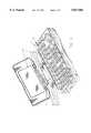
- FIG. 1is an exploded view of a PDA device according to the invention
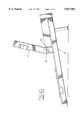
- FIG. 2is a cross-section of the device of FIG. 1 in the opened position
- FIG. 3presents the device of FIG. 2 in the closed position
- FIG. 4apresents a prior art device
- FIG. 4bpresents a detail of the device in FIG. 4a in a larger scale.
- FIGS. 1-3will be referred to in the following description of the invention and the preferred embodiments thereof.
- the base part of the PDA device presented in FIGS. 1-3is marked reference number 1.
- a first user interface(not shown in the figures) is provided on the outer surface of base part 1. This interface can be the same as those in known mobile phones.
- Keyboard 14 of the second user interfaceis provided on the opposite outer surface of base part 1.
- Cover part 2which is provided with display 15 of the second user interface is pivotally mounted on the long side of base part 1 by using a hinge structure comprising a first pair of hinges and a second pair of hinges.
- the first pair of hingesconsists of hinge sleeve 4 attached to base part 1, hinge sleeve 5 attached to cover part 2, and pivot pin 6 connecting the two, and helical spring 7.
- the second pair of hingescorrespondingly consist of hinge sleeve 8 attached to base part 1, hinge sleeve 9 attached to cover part 2, and pivot pin 10 connecting the two, and of helical spring 11.
- An elongated, cylindrical, pivotal connecting piece 3is provided between the first and the second pair of hinges, provided with holes 16 at the ends thereof. The said pivot pins are pushed into the holes, keeping the connecting piece 3 in place between hinge sleeves 4 and 8.
- Connecting piece 3comprises a slot for flat cable 12, and a hole for RF cable 13.
- Flat cable 12 and RF cable 13each travel through connecting piece 3 essentially perpendicular to the slewing axis.
- cylindrical connecting piece 3The outer surface of cylindrical connecting piece 3 is provided with two axial projections 17 and 18 which are placed essentially diametrally to each other.
- Cover part 2is provided with stops 19 and 20 for projection 17, and base part 1 is provided with stop 21 for projection 18.
- the projections and stops and the diameter of the connecting piecetogether determine spread angle a of the cover part and slewing angle ⁇ of the connecting piece.
- cover part 2turns from the closed position, when the device is opened, to the extent of a certain angle while connecting piece 3 as well as cables 12 and 13 remain fixed.
- the anglemay be, e.g., about 90°, but it is obvious that it can also be something else.
- stop 19meets projection 17, whereby connecting piece 3 turns along with the cover part until projection 18 meets stop 21.
- the connecting piecehas turned to the extent of angle ⁇ and the cover part has turned to the extent of angle ⁇ , and the device is in its operational position (FIG. 2).
- cover part 2turns to the extent of a certain angle while connecting piece 3 remains fixed.
- stop 20meets projection 17, whereby connecting piece 3 turns along with cover part 2 until the device is closed (FIG. 3). Cables 12 and 13 move and are exposed to bending only when connecting piece 3 is turned.
Landscapes
- Engineering & Computer Science (AREA)
- Theoretical Computer Science (AREA)
- Computer Hardware Design (AREA)
- Physics & Mathematics (AREA)
- Human Computer Interaction (AREA)
- General Engineering & Computer Science (AREA)
- General Physics & Mathematics (AREA)
- Mathematical Physics (AREA)
- Computer Networks & Wireless Communication (AREA)
- Telephone Set Structure (AREA)
- Pivots And Pivotal Connections (AREA)
- Hinge Accessories (AREA)
- Calculators And Similar Devices (AREA)
Abstract
Description
The invention is related to a device comprising a base part, a pivoting part, and a hinge structure comprising a first pair of hinges and a second pair of hinges, the hinge structure being used to pivotally mount the pivoting part on the base part; and an electric connection means between the base part and the pivoting part.
U.S. Pat. publication 4,571,456 discloses a portable computer according to the appended FIGS. 4a and 4b, comprisingbase part 22,display unit 23, andcable 24 between the base part and the display unit.Display unit 23 is pivotally mounted onbase part 22 byhinge structure 25.Cable 24 travels through the hinge in the direction of the hinge line, whereby, when the display unit is opened and closed, torsion is exerted on the cable to the extent of the spread angle of the display unit, causing stress on the cable. This structure is only applicable for round cables but not for, e.g., flat cables which require a larger space. Another disadvantage of this known device is that it is difficult to disassemble and reassemble for maintenance.
Publication WO-90/10818 discloses a portable computer comprising a base part and a display unit pivotally mounted on the base part, and a flat cable between the base part and the display unit. In this solution, the specially built flat cable travels inside a split pivot pin in the direction of the hinge line. At the entry point of the flat cable, there is provided an extra length of loose cable which enables the cable to wind around the pivot pin when the hinge is pivoted.
Organizer-type devices employ a hinge structure in which the input opening of the cables is implemented perpendicular to the hinge line, whereby the bending radius of the cables are small and the bending angle is as large as the spread angle of the device. This may cause stress on the cables, and furthermore, the cables must be provided with an extra length of loose cable.
The object of the invention is to provide a device comprising a hinge structure for cable input openings which avoids the disadvantages of the above-mentioned known solutions, and which is simple in structure and easy to assemble and disassemble. Thus, the object of the invention is particularly to provide a hinge structure that is well-adapted for input openings of different types of cables, including flat cables, and in which the stress exerted on the cables is small.
These objects are achieved with the device according to the invention, the main features thereof being apparent from the appended Claims.
Consequently, the invention comprises a device comprising a base part, a pivoting part, and a hinge structure comprising a first pair of hinges and a second pair of hinges, the hinge structure being used to pivotally mount the pivoting part on the base part, and electric connection means between the base part and the pivoting part, the device being characterised in that a connecting piece is provided between the first pair of hinges and the second pair of hinges, through which the electric connection means are taken and which is adapted to partly pivot along with the pivoting part, the swing angle β of the connecting piece being smaller than the swing angle α of the hinge, i.e., the spread angle of the device.
According to a preferred embodiment, the said connecting piece comprises a member that allows the connecting piece to partly swing along with the pivoting part. This member may comprise a projecting part on the outer surface of the connecting piece, whereby the pivoting part comprises stops for the projecting part, respectively.
The connecting piece may also comprise another projecting part, whereby the base part, correspondingly, is provided with a stop for the second projecting part for restricting the swinging of the pivoting part and for keeping the pivoting part at a desired angle α with respect to the base part.
The connecting piece is preferably an elongated cylindrical piece.
The electric connection means, such as flat cables and/or round cables, can be taken through the connecting piece perpendicularly or obliquely with respect to the slewing axis.
Each said pair of hinges may comprise a hinge sleeve attached to the base part and a hinge sleeve attached to the pivoting part, and a pivot pin that connects the two, whereby holes are provided at both ends of the connecting piece. Thus the pivot pins extend into the holes and keep the connecting piece in place between the pairs of hinges. A spring(s) can also be provided to press the connecting piece in place between the pairs of hinges.
As described above, the swing angle β of the pivoting connecting piece in the device according to the invention is smaller than the swing angle α of the hinge, i.e., the spread angle of the device. The smaller spread angle allows less stress on the cables. Consequently, the bending radius of the cables can be increased and the bending angle decreased by using the pivoting connecting piece. In addition, the diameter of the hinge becomes small. These matters are of importance since coaxial cables, for instance, do not tolerate sharp angles.
The size of the spread angle α of the device according to the invention is directly proportional to the diameter of the hinge, i.e., the connecting piece.
The device according to the invention can be, e.g., a PDA device, in other words, a dual-purpose data transmission device with two separate user interfaces. The first user interface is essentially similar to the presently well-known user interface of a mobile phone. It is placed on the outer surface of the device and preferably comprises a speaker, a microphone, a numeric keypad, and a fairly small display. To use the second user interface, this so-called dual-purpose data transmission device is opened with the aid of the said pivoting, hinged part, whereby a large display and a full alphanumeric keyboard, the so-called QWERTY keyboard, are exposed from the inside of the device. The intention is that, with the aid of the first user interface, the device can be used in the same manner as an ordinary mobile phone of a cellular network, whereby the device can be kept closed and it is easy to handle because of its compact shape and small size. The second user interface can be used to transmit and receive textual and graphical messages, intercomputer data messages, and telefax messages, and to use the notepad or calendar functions, and possible additional functions such as the pocket calculator program, the electronic dictionary, and so on. The user interfaces of the device can be used both independently and simultaneously, i.e., in the middle of a telephone call, the user can open the device and check an agreed appointment on the calendar or write an important piece of information on the notepad.
In addition to the dual-purpose data transmission device described above, the device according to the invention may be any device consisting of two or more parts, such as laptop- and palmtop-type computers. The parts should be joined by a hinge to decrease the size, and connected by cables to provide an electric connection.
In the following, the invention is described in detail with reference to the appended drawings in which:
FIG. 1 is an exploded view of a PDA device according to the invention,
FIG. 2 is a cross-section of the device of FIG. 1 in the opened position,
FIG. 3 presents the device of FIG. 2 in the closed position,
FIG. 4a presents a prior art device, and
FIG. 4b presents a detail of the device in FIG. 4a in a larger scale.
In connection with the prior art description above, a reference was made to FIGS. 4a and 4b, therefore, FIGS. 1-3 will be referred to in the following description of the invention and the preferred embodiments thereof. The base part of the PDA device presented in FIGS. 1-3 is marked reference number 1. A first user interface (not shown in the figures) is provided on the outer surface of base part 1. This interface can be the same as those in known mobile phones.Keyboard 14 of the second user interface is provided on the opposite outer surface of base part 1.Cover part 2 which is provided withdisplay 15 of the second user interface is pivotally mounted on the long side of base part 1 by using a hinge structure comprising a first pair of hinges and a second pair of hinges. The first pair of hinges consists of hinge sleeve 4 attached to base part 1, hinge sleeve 5 attached to coverpart 2, andpivot pin 6 connecting the two, and helical spring 7. The second pair of hinges correspondingly consist ofhinge sleeve 8 attached to base part 1, hinge sleeve 9 attached to coverpart 2, andpivot pin 10 connecting the two, and of helical spring 11.
An elongated, cylindrical, pivotal connectingpiece 3 is provided between the first and the second pair of hinges, provided withholes 16 at the ends thereof. The said pivot pins are pushed into the holes, keeping the connectingpiece 3 in place betweenhinge sleeves 4 and 8.
Connectingpiece 3 comprises a slot forflat cable 12, and a hole for RF cable 13.Flat cable 12 and RF cable 13 each travel through connectingpiece 3 essentially perpendicular to the slewing axis.
The outer surface of cylindrical connectingpiece 3 is provided with twoaxial projections part 2 is provided withstops projection 17, and base part 1 is provided withstop 21 forprojection 18. The projections and stops and the diameter of the connecting piece together determine spread angle a of the cover part and slewing angle β of the connecting piece.
Referring to FIGS. 2 and 3, coverpart 2 turns from the closed position, when the device is opened, to the extent of a certain angle while connectingpiece 3 as well ascables 12 and 13 remain fixed. The angle may be, e.g., about 90°, but it is obvious that it can also be something else. Thereafter, stop 19 meetsprojection 17, whereby connectingpiece 3 turns along with the cover part untilprojection 18 meets stop 21. By this time the connecting piece has turned to the extent of angle β and the cover part has turned to the extent of angle α, and the device is in its operational position (FIG. 2). When the device is closed, coverpart 2 turns to the extent of a certain angle while connectingpiece 3 remains fixed. Thereafter, stop 20 meetsprojection 17, whereby connectingpiece 3 turns along withcover part 2 until the device is closed (FIG. 3).Cables 12 and 13 move and are exposed to bending only when connectingpiece 3 is turned.
Only one preferred embodiment of the invention is described above and it is obvious that many modifications are possible within the appended Claims.
Claims (10)
1. A device comprising a base part (1), a pivoting part (2) pivoting through a given slewing angle α relative to said base part, and a hinge structure comprising a first pair of hinges (4, 5, 6) and a second pair of hinges (8, 9, 10), the hinge structure being used to pivotally mount the pivoting part on the base part, and electric connection means (12, 13) between the base part and the pivoting part, characterised in that a connecting piece (3) is provided between the first pair of hinges (4, 5, 6) and the second pair of hinges (8, 9, 10), said connecting piece pivoting through a given slewing angle β, the electric connection means (12, 13) having been taken through the connecting piece, and the connecting piece being adapted to partly pivot along with the pivoting part (2), the slewing angle β of the connecting piece being smaller than the slewing angle α of the pivoting part.
2. A device according to claim 1, characterised in that the connecting piece (3) is provided with a member (17) which allows the connecting piece to partly pivot along with the pivoting part (2).
3. A device according to claim 2, characterised in that the said member comprises a projection (17) on the outer surface of the connecting piece (3) and that the pivoting part (2) is provided with stops (19, 20) for the projection.
4. A device according to claim 3, characterised in that the connecting piece (3) is further provided with a second projection (18) and that the base part (1) is provided with a stop (21) for the second projection to restrict the pivoting of the pivoting part (2) and to keep the pivoting part (2) in a desired angle α with respect to the base part (1).
5. A device according to claim 1, characterised in that the connecting piece (3) is an elongated cylindrical body.
6. A device according to claim 1, characterised in that the electric connection means (12, 13) have been taken through the connecting piece (3) perpendicularly or obliquely to the slewing axis.
7. A device according to claim 6, characterised in that the electric connection means (12, 13) only move when the connecting piece (3) is moved.
8. A device according to claim 1, characterised in that each pair of hinges (4, 5, 6; 8, 9, 10) comprises a hinge sleeve (4; 8) attached to the base part (1) and a hinge sleeve (5; 9) attached to the pivoting part (2), and a pivot pin (6; 10) connecting the two.
9. A device according to claim 8, characterised in that the connecting piece (3) comprises holes (16) at both ends thereof and that the pivot pins (6, 10) extend into the holes, keeping the connecting piece in place between the pairs of hinges.
10. A device according to claim 8, characterised in that spring force is used to keep the connecting piece in place between the pairs of hinges.
Applications Claiming Priority (2)
| Application Number | Priority Date | Filing Date | Title |
|---|---|---|---|
| FI956225 | 1995-12-22 | ||
| FI956225AFI100038B (en) | 1995-12-22 | 1995-12-22 | Apparatus fitted with hinges |
Publications (1)
| Publication Number | Publication Date |
|---|---|
| US5827082Atrue US5827082A (en) | 1998-10-27 |
Family
ID=8544601
Family Applications (1)
| Application Number | Title | Priority Date | Filing Date |
|---|---|---|---|
| US08/763,931Expired - LifetimeUS5827082A (en) | 1995-12-22 | 1996-12-12 | Hinged device |
Country Status (7)
| Country | Link |
|---|---|
| US (1) | US5827082A (en) |
| EP (1) | EP1023753B1 (en) |
| JP (1) | JP2000502779A (en) |
| AU (1) | AU1177997A (en) |
| DE (1) | DE69634347T2 (en) |
| FI (1) | FI100038B (en) |
| WO (1) | WO1997023936A1 (en) |
Cited By (43)
| Publication number | Priority date | Publication date | Assignee | Title |
|---|---|---|---|---|
| US5951312A (en)* | 1997-07-22 | 1999-09-14 | Horng; Chin-Fu | Accommodating hinge mechanism |
| US6338182B1 (en)* | 2000-01-28 | 2002-01-15 | Hon Hai Precision Ind. Co., Ltd. | Hinge assembly |
| US6366785B2 (en) | 1998-01-07 | 2002-04-02 | Nokia Mobile Phones Limited | Telephone services |
| US20020044136A1 (en)* | 1998-06-26 | 2002-04-18 | Griffin Jason T. | Dual-mode mobile communication device |
| US6384813B1 (en) | 1998-06-30 | 2002-05-07 | Nokia Mobile Phones Limited | Two-part electronic device |
| US6413103B1 (en)* | 2000-11-28 | 2002-07-02 | Apple Computer, Inc. | Method and apparatus for grounding microcoaxial cables inside a portable computing device |
| US20020111186A1 (en)* | 2001-02-15 | 2002-08-15 | Yung-Fa Cheng | Mobile phone with base-detachable hinge structure |
| US6445577B1 (en)* | 2000-09-20 | 2002-09-03 | 3Com Corporation | Case with communication module having a double pin hinge for a handheld computer system |
| US20020149567A1 (en)* | 1998-06-26 | 2002-10-17 | Griffin Jason T. | Hand-held electronic device |
| US6490443B1 (en) | 1999-09-02 | 2002-12-03 | Automated Business Companies | Communication and proximity authorization systems |
| US20030020692A1 (en)* | 1998-06-26 | 2003-01-30 | Griffin Jason T. | Hand-held electronic device with a keyboard optimized for use with the thumbs |
| US6568947B2 (en)* | 2000-10-13 | 2003-05-27 | Nokia Mobile Phone Limited | Apparatus for routing a flexible circuit |
| US20030206156A1 (en)* | 1998-06-26 | 2003-11-06 | Griffin Jason T. | Hand-held electronic device with a keyboard optimized for use with the thumbs |
| USD497907S1 (en) | 2002-01-08 | 2004-11-02 | Research In Motion Limited | Keyboard for use with a handheld electronic device |
| US20050054393A1 (en)* | 2003-09-10 | 2005-03-10 | Nokia Corporation | Movable functional elements for mobile communication device |
| US20050091431A1 (en)* | 2003-10-23 | 2005-04-28 | Robert Olodort | Portable communication devices |
| USD514541S1 (en) | 2004-05-17 | 2006-02-07 | Research In Motion Limited | Handheld communication device |
| USD516548S1 (en) | 2004-05-17 | 2006-03-07 | Research In Motion Limited | Handheld communication device |
| USD517056S1 (en) | 2004-05-17 | 2006-03-14 | Research In Motion Limited | Handheld communication device |
| USD522486S1 (en) | 2004-05-17 | 2006-06-06 | Research In Motion Limited | Handheld communication device |
| US7083342B2 (en) | 2001-12-21 | 2006-08-01 | Griffin Jason T | Keyboard arrangement |
| US7109973B2 (en) | 2003-05-14 | 2006-09-19 | Research In Motion Limited | Mobile device with rotatable keyboard |
| USD538281S1 (en) | 2003-03-06 | 2007-03-13 | Thom Gambaro | Two-thumb keyboard device |
| US20070101541A1 (en)* | 2005-11-04 | 2007-05-10 | Shenzhen Futaihong Precision Industrial Co., Ltd. | Hinge assembly for portable electronic devices |
| US20070192713A1 (en)* | 2006-02-13 | 2007-08-16 | Research In Motion Limited | Method and arrangement for providing a primary actions menu on a handheld communication device having a full alphabetic keyboard |
| US20070211034A1 (en)* | 2006-02-13 | 2007-09-13 | Griffin Jason T | Handheld wireless communication device with function keys in exterior key columns |
| US7439959B2 (en) | 2004-07-30 | 2008-10-21 | Research In Motion Limited | Key arrangement for a keyboard |
| USD588119S1 (en) | 2004-02-24 | 2009-03-10 | Research In Motion Limited | Keyboard for a handheld mobile communication device |
| US7561685B2 (en) | 2001-12-21 | 2009-07-14 | Research In Motion Limited | Handheld electronic device with keyboard |
| US7669144B2 (en) | 2006-02-13 | 2010-02-23 | Research In Motion Limited | Method and arrangment for a primary actions menu including one menu item for applications on a handheld electronic device |
| US20100090990A1 (en)* | 2001-10-19 | 2010-04-15 | Research In Motion Limited | Hand-held electronic device with multiple input mode thumbwheel |
| US20110102986A1 (en)* | 2009-11-05 | 2011-05-05 | Panasonic Corporation | Electronic equipment with hinge mechanism |
| US8064946B2 (en) | 2004-06-21 | 2011-11-22 | Research In Motion Limited | Handheld wireless communication device |
| US8219158B2 (en) | 2004-06-21 | 2012-07-10 | Research In Motion Limited | Handheld wireless communication device |
| US20120206864A1 (en)* | 2011-02-10 | 2012-08-16 | Microsoft Corporation | Hinge electrical interconnection guide |
| US8271036B2 (en) | 2004-06-21 | 2012-09-18 | Research In Motion Limited | Handheld wireless communication device |
| US8419303B2 (en) | 2003-12-31 | 2013-04-16 | Research In Motion Limited | Keyboard with overlaid numeric phone keypad |
| US8463315B2 (en) | 2004-06-21 | 2013-06-11 | Research In Motion Limited | Handheld wireless communication device |
| US8773849B2 (en) | 2011-04-11 | 2014-07-08 | Microsoft Corporation | Extendable connecting link |
| US8780570B2 (en) | 2011-02-14 | 2014-07-15 | Microsoft Corporation | Double hinge torsion bar |
| US8904286B2 (en) | 2006-02-13 | 2014-12-02 | Blackberry Limited | Method and arrangement for providing a primary actions menu on a wireless handheld communication device |
| CN104565014A (en)* | 2013-10-09 | 2015-04-29 | 纬创资通股份有限公司 | Pivot structure and electronic device with same |
| TWI495986B (en)* | 2013-01-30 | 2015-08-11 | Wistron Corp | Electronic device with hinge mechanism |
Families Citing this family (10)
| Publication number | Priority date | Publication date | Assignee | Title |
|---|---|---|---|---|
| FI980603L (en)* | 1998-03-18 | 1999-09-19 | Nokia Mobile Phones Ltd | Hinged electronic device |
| JP2001054084A (en)* | 1999-08-09 | 2001-02-23 | Matsushita Electric Ind Co Ltd | Videophone equipment |
| FI19992611A7 (en) | 1999-12-03 | 2001-06-04 | Nokia Corp | Hinged transmitter and/or receiver type electronic device |
| GB2409497B (en) | 2003-12-23 | 2007-06-20 | Nokia Corp | Modular hinge for handheld electronic devices |
| JP4597072B2 (en)* | 2006-02-27 | 2010-12-15 | 東芝テック株式会社 | Handy terminal |
| DE102007041816B4 (en)* | 2007-09-03 | 2009-08-27 | Simonswerk, Gesellschaft mit beschränkter Haftung | Door hinge with electric cable |
| JP2010185232A (en)* | 2009-02-13 | 2010-08-26 | Takigen Mfg Co Ltd | Hinge device |
| JP5620429B2 (en)* | 2011-05-09 | 2014-11-05 | 株式会社クローバー | Dial lock |
| DE102013108973B3 (en)* | 2013-08-20 | 2014-09-11 | Simonswerk, Gesellschaft mit beschränkter Haftung | Hinge and door arrangement |
| JP2015084351A (en)* | 2013-10-25 | 2015-04-30 | 理想科学工業株式会社 | Tilt mechanism |
Citations (9)
| Publication number | Priority date | Publication date | Assignee | Title |
|---|---|---|---|---|
| US4571456A (en)* | 1982-10-18 | 1986-02-18 | Grid Systems Corporation | Portable computer |
| WO1990010818A1 (en)* | 1989-03-06 | 1990-09-20 | Dynabook Technologies Corporation | Torsion bar and band brake |
| US4986763A (en)* | 1989-03-06 | 1991-01-22 | Dynabook Technologies Cororation | Contact strip-to-flex bushing connector |
| US5007849A (en)* | 1989-03-27 | 1991-04-16 | Brother Kogyo Kabushiki Kaisha | Signal line connecting structure for a keyboard of electronic apparatus |
| US5127842A (en)* | 1991-11-04 | 1992-07-07 | Kelly Steven M | Rotating electrical connector |
| US5141446A (en)* | 1990-07-04 | 1992-08-25 | Alcatel Radiotelephone | Device comprising two components that are hinged together and that are interconnected by an electrical connection |
| US5328379A (en)* | 1989-06-23 | 1994-07-12 | Kabushiki Kaisha Toshiba | Portable apparatus having cable electrically connecting display unit and base unit |
| US5581440A (en)* | 1992-09-18 | 1996-12-03 | Ast Research, Inc. | Rotatable bushing for reducing bending stress in electrical cable |
| US5661797A (en)* | 1995-11-01 | 1997-08-26 | Nokia Mobile Phones Ltd. | Hinge mechanism for cellular transceiver housing |
- 1995
- 1995-12-22FIFI956225Apatent/FI100038B/ennot_activeIP Right Cessation
- 1996
- 1996-12-12USUS08/763,931patent/US5827082A/ennot_activeExpired - Lifetime
- 1996-12-20JPJP09523346Apatent/JP2000502779A/enactivePending
- 1996-12-20WOPCT/FI1996/000682patent/WO1997023936A1/enactiveIP Right Grant
- 1996-12-20EPEP96942379Apatent/EP1023753B1/ennot_activeExpired - Lifetime
- 1996-12-20DEDE69634347Tpatent/DE69634347T2/ennot_activeExpired - Lifetime
- 1996-12-20AUAU11779/97Apatent/AU1177997A/ennot_activeAbandoned
Patent Citations (10)
| Publication number | Priority date | Publication date | Assignee | Title |
|---|---|---|---|---|
| US4571456A (en)* | 1982-10-18 | 1986-02-18 | Grid Systems Corporation | Portable computer |
| US4571456B1 (en)* | 1982-10-18 | 1995-08-15 | Grid Systems Corp | Portable computer |
| WO1990010818A1 (en)* | 1989-03-06 | 1990-09-20 | Dynabook Technologies Corporation | Torsion bar and band brake |
| US4986763A (en)* | 1989-03-06 | 1991-01-22 | Dynabook Technologies Cororation | Contact strip-to-flex bushing connector |
| US5007849A (en)* | 1989-03-27 | 1991-04-16 | Brother Kogyo Kabushiki Kaisha | Signal line connecting structure for a keyboard of electronic apparatus |
| US5328379A (en)* | 1989-06-23 | 1994-07-12 | Kabushiki Kaisha Toshiba | Portable apparatus having cable electrically connecting display unit and base unit |
| US5141446A (en)* | 1990-07-04 | 1992-08-25 | Alcatel Radiotelephone | Device comprising two components that are hinged together and that are interconnected by an electrical connection |
| US5127842A (en)* | 1991-11-04 | 1992-07-07 | Kelly Steven M | Rotating electrical connector |
| US5581440A (en)* | 1992-09-18 | 1996-12-03 | Ast Research, Inc. | Rotatable bushing for reducing bending stress in electrical cable |
| US5661797A (en)* | 1995-11-01 | 1997-08-26 | Nokia Mobile Phones Ltd. | Hinge mechanism for cellular transceiver housing |
Cited By (94)
| Publication number | Priority date | Publication date | Assignee | Title |
|---|---|---|---|---|
| US5951312A (en)* | 1997-07-22 | 1999-09-14 | Horng; Chin-Fu | Accommodating hinge mechanism |
| US6366785B2 (en) | 1998-01-07 | 2002-04-02 | Nokia Mobile Phones Limited | Telephone services |
| US20030206156A1 (en)* | 1998-06-26 | 2003-11-06 | Griffin Jason T. | Hand-held electronic device with a keyboard optimized for use with the thumbs |
| US20100073300A1 (en)* | 1998-06-26 | 2010-03-25 | Research In Motion Limited | Hand-held electronic device with a keyboard optimized for use with the thumbs |
| US9367141B2 (en) | 1998-06-26 | 2016-06-14 | Blackberry Limited | Hand-held electronic device with a keyboard optimized for use with the thumbs |
| US7227536B2 (en) | 1998-06-26 | 2007-06-05 | Research In Motion Limited | Hand-held electronic device with a keyboard optimized for use with the thumbs |
| US7629964B2 (en) | 1998-06-26 | 2009-12-08 | Research In Motion Limited | Hand-held electronic device with a keyboard optimized for use with the thumbs |
| US8464149B2 (en) | 1998-06-26 | 2013-06-11 | Research In Motion Limited | Hand-held electronic device with autopunctuation |
| US20020149567A1 (en)* | 1998-06-26 | 2002-10-17 | Griffin Jason T. | Hand-held electronic device |
| US6873317B1 (en) | 1998-06-26 | 2005-03-29 | Research In Motion Limited | Hand-held electronic device with a keyboard optimized for use with the thumbs |
| US20030020692A1 (en)* | 1998-06-26 | 2003-01-30 | Griffin Jason T. | Hand-held electronic device with a keyboard optimized for use with the thumbs |
| US7158120B2 (en) | 1998-06-26 | 2007-01-02 | Research In Motion Limited | Hand-held electronic device |
| US8493322B2 (en) | 1998-06-26 | 2013-07-23 | Research In Motion Limited | Hand-held electronic device |
| US6867763B2 (en) | 1998-06-26 | 2005-03-15 | Research In Motion Limited | Hand-held electronic device with a keyboard optimized for use with the thumbs |
| US20020044136A1 (en)* | 1998-06-26 | 2002-04-18 | Griffin Jason T. | Dual-mode mobile communication device |
| US9134759B2 (en) | 1998-06-26 | 2015-09-15 | Blackberry Limited | Dual-mode mobile communication device |
| US7705828B2 (en) | 1998-06-26 | 2010-04-27 | Research In Motion Limited | Dual-mode mobile communication device |
| US20100164872A1 (en)* | 1998-06-26 | 2010-07-01 | Research In Motion Limited | Dual-mode mobile communication device |
| US6919879B2 (en) | 1998-06-26 | 2005-07-19 | Research In Motion Limited | Hand-held electronic device with a keyboard optimized for use with the thumbs |
| US10067572B2 (en) | 1998-06-26 | 2018-09-04 | Blackberry Limited | Hand-held electronic device |
| US8416195B2 (en) | 1998-06-26 | 2013-04-09 | Research In Motion Limited | Hand-held electronic device with a keyboard optimized for use with the thumbs |
| US9703390B2 (en) | 1998-06-26 | 2017-07-11 | Blackberry Limited | Hand-held electronic device |
| US6384813B1 (en) | 1998-06-30 | 2002-05-07 | Nokia Mobile Phones Limited | Two-part electronic device |
| US6490443B1 (en) | 1999-09-02 | 2002-12-03 | Automated Business Companies | Communication and proximity authorization systems |
| US8958846B2 (en) | 1999-09-02 | 2015-02-17 | Charles Freeny, III | Communication and proximity authorization systems |
| US6338182B1 (en)* | 2000-01-28 | 2002-01-15 | Hon Hai Precision Ind. Co., Ltd. | Hinge assembly |
| US6445577B1 (en)* | 2000-09-20 | 2002-09-03 | 3Com Corporation | Case with communication module having a double pin hinge for a handheld computer system |
| US6568947B2 (en)* | 2000-10-13 | 2003-05-27 | Nokia Mobile Phone Limited | Apparatus for routing a flexible circuit |
| US6413103B1 (en)* | 2000-11-28 | 2002-07-02 | Apple Computer, Inc. | Method and apparatus for grounding microcoaxial cables inside a portable computing device |
| US6999801B2 (en)* | 2001-02-15 | 2006-02-14 | Quanta Computer, Inc. | Base-detachable hinge structure for mobile phone |
| US20020111186A1 (en)* | 2001-02-15 | 2002-08-15 | Yung-Fa Cheng | Mobile phone with base-detachable hinge structure |
| US20100090990A1 (en)* | 2001-10-19 | 2010-04-15 | Research In Motion Limited | Hand-held electronic device with multiple input mode thumbwheel |
| US8144135B2 (en) | 2001-10-19 | 2012-03-27 | Research In Motion Limited | Hand-held electronic device with multiple input mode thumbwheel |
| US7952571B2 (en) | 2001-10-19 | 2011-05-31 | Research In Motion Limited | Hand-held electronic device with multiple input mode thumbwheel |
| US7561685B2 (en) | 2001-12-21 | 2009-07-14 | Research In Motion Limited | Handheld electronic device with keyboard |
| US7819598B2 (en) | 2001-12-21 | 2010-10-26 | Research In Motion Limited | Keyboard arrangement |
| US8824669B2 (en) | 2001-12-21 | 2014-09-02 | Blackberry Limited | Handheld electronic device with keyboard |
| US7083342B2 (en) | 2001-12-21 | 2006-08-01 | Griffin Jason T | Keyboard arrangement |
| USD497907S1 (en) | 2002-01-08 | 2004-11-02 | Research In Motion Limited | Keyboard for use with a handheld electronic device |
| USD538281S1 (en) | 2003-03-06 | 2007-03-13 | Thom Gambaro | Two-thumb keyboard device |
| US7109973B2 (en) | 2003-05-14 | 2006-09-19 | Research In Motion Limited | Mobile device with rotatable keyboard |
| US20050054393A1 (en)* | 2003-09-10 | 2005-03-10 | Nokia Corporation | Movable functional elements for mobile communication device |
| US7283852B2 (en) | 2003-09-10 | 2007-10-16 | Nokia Corporation | Movable functional elements for mobile communication device |
| US20050091431A1 (en)* | 2003-10-23 | 2005-04-28 | Robert Olodort | Portable communication devices |
| US7938589B2 (en) | 2003-12-31 | 2011-05-10 | Research In Motion Limited | Keyboard arrangement |
| US8419303B2 (en) | 2003-12-31 | 2013-04-16 | Research In Motion Limited | Keyboard with overlaid numeric phone keypad |
| USD588119S1 (en) | 2004-02-24 | 2009-03-10 | Research In Motion Limited | Keyboard for a handheld mobile communication device |
| USD517056S1 (en) | 2004-05-17 | 2006-03-14 | Research In Motion Limited | Handheld communication device |
| USD523007S1 (en) | 2004-05-17 | 2006-06-13 | Research In Motion Limited | Keyboard for a handheld communication device |
| USD516548S1 (en) | 2004-05-17 | 2006-03-07 | Research In Motion Limited | Handheld communication device |
| USD528098S1 (en) | 2004-05-17 | 2006-09-12 | Research In Motion Limited | Housing for a handheld communication device |
| USD521506S1 (en) | 2004-05-17 | 2006-05-23 | Research In Motion Limited | Keyboard for a handheld communication device |
| USD521485S1 (en) | 2004-05-17 | 2006-05-23 | Research In Motion Limited | Handheld communication device |
| USD525619S1 (en) | 2004-05-17 | 2006-07-25 | Research In Motion Limited | Keyboard for a handheld communication device |
| USD516547S1 (en) | 2004-05-17 | 2006-03-07 | Research In Motion Limited | Handheld communication device |
| USD525223S1 (en) | 2004-05-17 | 2006-07-18 | Research In Motion Limited | Handheld communication device |
| USD525244S1 (en) | 2004-05-17 | 2006-07-18 | Research In Motion Limited | Speaker port for a handheld communication device |
| USD525243S1 (en) | 2004-05-17 | 2006-07-18 | Research In Motion Limited | Speaker port for a handheld communication device |
| USD514541S1 (en) | 2004-05-17 | 2006-02-07 | Research In Motion Limited | Handheld communication device |
| USD525222S1 (en) | 2004-05-17 | 2006-07-18 | Research In Motion Limited | Handheld communication device |
| USD524803S1 (en) | 2004-05-17 | 2006-07-11 | Research In Motion Limited | Keyboard for a handheld communication device |
| USD524302S1 (en) | 2004-05-17 | 2006-07-04 | Research In Motion Limited | Keyboard for a handheld communication device |
| USD524303S1 (en) | 2004-05-17 | 2006-07-04 | Research In Motion Limited | Keyboard for a handheld communication device |
| USD523423S1 (en) | 2004-05-17 | 2006-06-20 | Research In Motion Limited | Keyboard for a handheld communication device |
| USD521973S1 (en) | 2004-05-17 | 2006-05-30 | Research In Motion Limited | Housing for a handheld communication device |
| USD523006S1 (en) | 2004-05-17 | 2006-06-13 | Research In Motion Limited | Keyboard for a handheld communication device |
| USD517037S1 (en) | 2004-05-17 | 2006-03-14 | Research In Motion Limited | Handheld communication device |
| USD521989S1 (en) | 2004-05-17 | 2006-05-30 | Research In Motion Limited | Speaker port for a handheld communication device |
| USD522485S1 (en) | 2004-05-17 | 2006-06-06 | Research In Motion Limited | Handheld communication device |
| USD522486S1 (en) | 2004-05-17 | 2006-06-06 | Research In Motion Limited | Handheld communication device |
| USD530712S1 (en) | 2004-05-17 | 2006-10-24 | Research In Motion Limited | Keyboard for a handheld communication device |
| USD522484S1 (en) | 2004-05-17 | 2006-06-06 | Research In Motion Limited | Housing for a handheld communication device |
| US8463315B2 (en) | 2004-06-21 | 2013-06-11 | Research In Motion Limited | Handheld wireless communication device |
| US8271036B2 (en) | 2004-06-21 | 2012-09-18 | Research In Motion Limited | Handheld wireless communication device |
| US8219158B2 (en) | 2004-06-21 | 2012-07-10 | Research In Motion Limited | Handheld wireless communication device |
| US8064946B2 (en) | 2004-06-21 | 2011-11-22 | Research In Motion Limited | Handheld wireless communication device |
| US7439959B2 (en) | 2004-07-30 | 2008-10-21 | Research In Motion Limited | Key arrangement for a keyboard |
| US8259074B2 (en) | 2004-07-30 | 2012-09-04 | Research In Motion Limited | Key arrangement for a keyboard |
| US20070101541A1 (en)* | 2005-11-04 | 2007-05-10 | Shenzhen Futaihong Precision Industrial Co., Ltd. | Hinge assembly for portable electronic devices |
| US8537117B2 (en) | 2006-02-13 | 2013-09-17 | Blackberry Limited | Handheld wireless communication device that selectively generates a menu in response to received commands |
| US7669144B2 (en) | 2006-02-13 | 2010-02-23 | Research In Motion Limited | Method and arrangment for a primary actions menu including one menu item for applications on a handheld electronic device |
| US20070211034A1 (en)* | 2006-02-13 | 2007-09-13 | Griffin Jason T | Handheld wireless communication device with function keys in exterior key columns |
| US8904286B2 (en) | 2006-02-13 | 2014-12-02 | Blackberry Limited | Method and arrangement for providing a primary actions menu on a wireless handheld communication device |
| US20070192713A1 (en)* | 2006-02-13 | 2007-08-16 | Research In Motion Limited | Method and arrangement for providing a primary actions menu on a handheld communication device having a full alphabetic keyboard |
| US20110102986A1 (en)* | 2009-11-05 | 2011-05-05 | Panasonic Corporation | Electronic equipment with hinge mechanism |
| US8593800B2 (en)* | 2009-11-05 | 2013-11-26 | Panasonic Corporation | Electronic equipment with hinge mechanism |
| US20120206864A1 (en)* | 2011-02-10 | 2012-08-16 | Microsoft Corporation | Hinge electrical interconnection guide |
| US9535465B2 (en)* | 2011-02-10 | 2017-01-03 | Microsoft Technology Licensing, Llc | Hinge electrical interconnection guide |
| US9069531B2 (en) | 2011-02-14 | 2015-06-30 | Microsoft Technology Licensing, Llc | Portable device and mobile phone with double hinge torsion bar |
| US8780570B2 (en) | 2011-02-14 | 2014-07-15 | Microsoft Corporation | Double hinge torsion bar |
| US8773849B2 (en) | 2011-04-11 | 2014-07-08 | Microsoft Corporation | Extendable connecting link |
| TWI495986B (en)* | 2013-01-30 | 2015-08-11 | Wistron Corp | Electronic device with hinge mechanism |
| CN104565014A (en)* | 2013-10-09 | 2015-04-29 | 纬创资通股份有限公司 | Pivot structure and electronic device with same |
| CN104565014B (en)* | 2013-10-09 | 2017-01-25 | 纬创资通股份有限公司 | Pivot structure and electronic device with same |
Also Published As
| Publication number | Publication date |
|---|---|
| DE69634347D1 (en) | 2005-03-17 |
| DE69634347T2 (en) | 2006-04-06 |
| EP1023753A1 (en) | 2000-08-02 |
| WO1997023936A1 (en) | 1997-07-03 |
| JP2000502779A (en) | 2000-03-07 |
| FI956225A0 (en) | 1995-12-22 |
| EP1023753B1 (en) | 2005-02-09 |
| AU1177997A (en) | 1997-07-17 |
| FI956225L (en) | 1997-06-23 |
| FI100038B (en) | 1997-08-29 |
Similar Documents
| Publication | Publication Date | Title |
|---|---|---|
| US5827082A (en) | Hinged device | |
| US7200224B2 (en) | Hinge device for portable wireless terminal | |
| EP1950937A2 (en) | Portable apparatus | |
| US7158634B2 (en) | Portable electronic devices | |
| US7130669B2 (en) | Portable information terminal having expandable data input unit | |
| US20010003707A1 (en) | Portable radio apparatus with additional display unit | |
| KR20050056147A (en) | Electronic device with improved hinge | |
| US7912523B2 (en) | Crescent hinge | |
| US20110148782A1 (en) | Electronic device | |
| US5657258A (en) | Mobile pen computer having an integrated palm rest | |
| EP2003529A2 (en) | Multimedia portable electronic device | |
| EP1901532A2 (en) | Flip-up type mobile phone | |
| US20070171195A1 (en) | Sliding/swing-type portable terminal capable of positioning liquid crystal display at center portion thereof and method of using the same | |
| US7206616B2 (en) | Handphone capable of inputting characters like keyboard | |
| CN1505365A (en) | foldable communication device | |
| KR19990071623A (en) | Hinged device | |
| KR200326417Y1 (en) | Sliding means of mobile phone of slide type | |
| KR100499885B1 (en) | Mobile communication terminal turning liquid crystal display | |
| KR100338638B1 (en) | Housing for radiotelephone with inputting unit | |
| KR100459559B1 (en) | Portable telephone with variable data inputting | |
| US20110131760A1 (en) | Hinge | |
| KR100402793B1 (en) | Portable terminal having a keyboard | |
| KR200211461Y1 (en) | Partable keyboard for mobile communication | |
| KR100592182B1 (en) | 360 degree rotating clamshell terminal | |
| CN101202778A (en) | Swing type hinge device of portable terminal and double hinge device having same |
Legal Events
| Date | Code | Title | Description |
|---|---|---|---|
| AS | Assignment | Owner name:NOKIA MOBILE PHONES LIMITED, FINLAND Free format text:ASSIGNMENT OF ASSIGNORS INTEREST;ASSIGNOR:LAINE, PASI;REEL/FRAME:008340/0709 Effective date:19961022 | |
| STCF | Information on status: patent grant | Free format text:PATENTED CASE | |
| FPAY | Fee payment | Year of fee payment:4 | |
| FPAY | Fee payment | Year of fee payment:8 | |
| FEPP | Fee payment procedure | Free format text:PAYOR NUMBER ASSIGNED (ORIGINAL EVENT CODE: ASPN); ENTITY STATUS OF PATENT OWNER: LARGE ENTITY | |
| FPAY | Fee payment | Year of fee payment:12 | |
| AS | Assignment | Owner name:NOKIA TECHNOLOGIES OY, FINLAND Free format text:ASSIGNMENT OF ASSIGNORS INTEREST;ASSIGNOR:NOKIA CORPORATION;REEL/FRAME:036067/0222 Effective date:20150116 |