US5826434A - High efficiency outdoor air conditioning system - Google Patents
High efficiency outdoor air conditioning systemDownload PDFInfo
- Publication number
- US5826434A US5826434AUS08/682,131US68213196AUS5826434AUS 5826434 AUS5826434 AUS 5826434AUS 68213196 AUS68213196 AUS 68213196AUS 5826434 AUS5826434 AUS 5826434A
- Authority
- US
- United States
- Prior art keywords
- air
- coil
- enthalpy wheel
- heat
- accordance
- Prior art date
- Legal status (The legal status is an assumption and is not a legal conclusion. Google has not performed a legal analysis and makes no representation as to the accuracy of the status listed.)
- Expired - Lifetime
Links
- 238000004378air conditioningMethods0.000titledescription14
- 230000001143conditioned effectEffects0.000claimsabstractdescription48
- 238000001816coolingMethods0.000claimsabstractdescription28
- 238000004891communicationMethods0.000claimsabstractdescription26
- 238000011084recoveryMethods0.000claimsabstractdescription20
- 239000002274desiccantSubstances0.000claimsdescription60
- 239000003507refrigerantSubstances0.000claimsdescription57
- 239000000835fiberSubstances0.000claimsdescription41
- 238000000034methodMethods0.000claimsdescription40
- 239000010457zeoliteSubstances0.000claimsdescription37
- HNPSIPDUKPIQMN-UHFFFAOYSA-Ndioxosilane;oxo(oxoalumanyloxy)alumaneChemical groupO=[Si]=O.O=[Al]O[Al]=OHNPSIPDUKPIQMN-UHFFFAOYSA-N0.000claimsdescription22
- VYPSYNLAJGMNEJ-UHFFFAOYSA-NSilicium dioxideChemical compoundO=[Si]=OVYPSYNLAJGMNEJ-UHFFFAOYSA-N0.000claimsdescription17
- 229910021536ZeoliteInorganic materials0.000claimsdescription17
- 239000000463materialSubstances0.000claimsdescription14
- -1polyethylenePolymers0.000claimsdescription13
- 239000002657fibrous materialSubstances0.000claimsdescription11
- 239000007788liquidSubstances0.000claimsdescription9
- 239000000377silicon dioxideSubstances0.000claimsdescription8
- 238000001704evaporationMethods0.000claimsdescription7
- 239000000499gelSubstances0.000claimsdescription6
- 229920003235aromatic polyamidePolymers0.000claimsdescription5
- 230000008020evaporationEffects0.000claimsdescription5
- 239000004743PolypropyleneSubstances0.000claimsdescription4
- PNEYBMLMFCGWSK-UHFFFAOYSA-Naluminium oxideInorganic materials[O-2].[O-2].[O-2].[Al+3].[Al+3]PNEYBMLMFCGWSK-UHFFFAOYSA-N0.000claimsdescription4
- 229920001155polypropylenePolymers0.000claimsdescription4
- 230000003750conditioning effectEffects0.000claimsdescription3
- 229920001778nylonPolymers0.000claimsdescription3
- 230000003134recirculating effectEffects0.000claims3
- 230000008016vaporizationEffects0.000claims3
- QTBSBXVTEAMEQO-UHFFFAOYSA-MAcetateChemical compoundCC([O-])=OQTBSBXVTEAMEQO-UHFFFAOYSA-M0.000claims2
- 239000004677NylonSubstances0.000claims2
- 239000004698PolyethyleneSubstances0.000claims2
- NIXOWILDQLNWCW-UHFFFAOYSA-Nacrylic acid groupChemical groupC(C=C)(=O)ONIXOWILDQLNWCW-UHFFFAOYSA-N0.000claims2
- 239000012530fluidSubstances0.000claims2
- 238000010438heat treatmentMethods0.000claims2
- 229920000573polyethylenePolymers0.000claims2
- 230000001172regenerating effectEffects0.000claims2
- 239000003463adsorbentSubstances0.000description38
- 239000000123paperSubstances0.000description36
- 239000002808molecular sieveSubstances0.000description12
- URGAHOPLAPQHLN-UHFFFAOYSA-Nsodium aluminosilicateChemical compound[Na+].[Al+3].[O-][Si]([O-])=O.[O-][Si]([O-])=OURGAHOPLAPQHLN-UHFFFAOYSA-N0.000description12
- 239000000203mixtureSubstances0.000description10
- 239000011087paperboardSubstances0.000description8
- 238000012546transferMethods0.000description8
- 239000011148porous materialSubstances0.000description7
- 239000011230binding agentSubstances0.000description6
- 239000000356contaminantSubstances0.000description6
- 238000004519manufacturing processMethods0.000description6
- 229910000323aluminium silicateInorganic materials0.000description5
- 150000001875compoundsChemical class0.000description5
- 229910052751metalInorganic materials0.000description5
- 239000002184metalSubstances0.000description5
- 239000011734sodiumSubstances0.000description5
- 229920000271Kevlar®Polymers0.000description4
- 239000004760aramidSubstances0.000description4
- 229920006231aramid fiberPolymers0.000description4
- 230000008901benefitEffects0.000description4
- 206010061592cardiac fibrillationDiseases0.000description4
- 238000007791dehumidificationMethods0.000description4
- 230000002600fibrillogenic effectEffects0.000description4
- 229910052708sodiumInorganic materials0.000description4
- 229920002972Acrylic fiberPolymers0.000description3
- WSFSSNUMVMOOMR-UHFFFAOYSA-NFormaldehydeChemical compoundO=CWSFSSNUMVMOOMR-UHFFFAOYSA-N0.000description3
- 150000001768cationsChemical class0.000description3
- 230000006835compressionEffects0.000description3
- 238000007906compressionMethods0.000description3
- 238000009826distributionMethods0.000description3
- 238000011068loading methodMethods0.000description3
- 239000002245particleSubstances0.000description3
- 238000001179sorption measurementMethods0.000description3
- 239000000126substanceSubstances0.000description3
- 238000009423ventilationMethods0.000description3
- 239000004793PolystyreneSubstances0.000description2
- 229920001131Pulp (paper)Polymers0.000description2
- 229920001577copolymerPolymers0.000description2
- 238000003795desorptionMethods0.000description2
- 229920001903high density polyethylenePolymers0.000description2
- 230000007935neutral effectEffects0.000description2
- 235000019645odorNutrition0.000description2
- 229920000642polymerPolymers0.000description2
- 229920002223polystyrenePolymers0.000description2
- 229910052700potassiumInorganic materials0.000description2
- 239000011591potassiumSubstances0.000description2
- 238000005057refrigerationMethods0.000description2
- 239000007787solidSubstances0.000description2
- 239000012855volatile organic compoundSubstances0.000description2
- XLYOFNOQVPJJNP-UHFFFAOYSA-NwaterSubstancesOXLYOFNOQVPJJNP-UHFFFAOYSA-N0.000description2
- 239000004953Aliphatic polyamideSubstances0.000description1
- 241000894006BacteriaSpecies0.000description1
- CPELXLSAUQHCOX-UHFFFAOYSA-MBromideChemical compound[Br-]CPELXLSAUQHCOX-UHFFFAOYSA-M0.000description1
- BHPQYMZQTOCNFJ-UHFFFAOYSA-NCalcium cationChemical group[Ca+2]BHPQYMZQTOCNFJ-UHFFFAOYSA-N0.000description1
- 229920003043Cellulose fiberPolymers0.000description1
- VEXZGXHMUGYJMC-UHFFFAOYSA-MChloride anionChemical compound[Cl-]VEXZGXHMUGYJMC-UHFFFAOYSA-M0.000description1
- 206010009866Cold sweatDiseases0.000description1
- RYGMFSIKBFXOCR-UHFFFAOYSA-NCopperChemical compound[Cu]RYGMFSIKBFXOCR-UHFFFAOYSA-N0.000description1
- XZMCDFZZKTWFGF-UHFFFAOYSA-NCyanamideChemical compoundNC#NXZMCDFZZKTWFGF-UHFFFAOYSA-N0.000description1
- UFHFLCQGNIYNRP-UHFFFAOYSA-NHydrogenChemical compound[H][H]UFHFLCQGNIYNRP-UHFFFAOYSA-N0.000description1
- DGAQECJNVWCQMB-PUAWFVPOSA-MIlexoside XXIXChemical compoundC[C@@H]1CC[C@@]2(CC[C@@]3(C(=CC[C@H]4[C@]3(CC[C@@H]5[C@@]4(CC[C@@H](C5(C)C)OS(=O)(=O)[O-])C)C)[C@@H]2[C@]1(C)O)C)C(=O)O[C@H]6[C@@H]([C@H]([C@@H]([C@H](O6)CO)O)O)O.[Na+]DGAQECJNVWCQMB-PUAWFVPOSA-M0.000description1
- 229920000784NomexPolymers0.000description1
- 229920000297RayonPolymers0.000description1
- 229910002796Si–AlInorganic materials0.000description1
- PPBRXRYQALVLMV-UHFFFAOYSA-NStyreneNatural productsC=CC1=CC=CC=C1PPBRXRYQALVLMV-UHFFFAOYSA-N0.000description1
- 229920001494TechnoraPolymers0.000description1
- 229920003367TeijinconexPolymers0.000description1
- RTAQQCXQSZGOHL-UHFFFAOYSA-NTitaniumChemical compound[Ti]RTAQQCXQSZGOHL-UHFFFAOYSA-N0.000description1
- 229920000561TwaronPolymers0.000description1
- 229920006397acrylic thermoplasticPolymers0.000description1
- 229920003231aliphatic polyamidePolymers0.000description1
- 229910052782aluminiumInorganic materials0.000description1
- XAGFODPZIPBFFR-UHFFFAOYSA-NaluminiumChemical compound[Al]XAGFODPZIPBFFR-UHFFFAOYSA-N0.000description1
- 150000001408amidesChemical class0.000description1
- 238000013459approachMethods0.000description1
- 125000003118aryl groupChemical group0.000description1
- 230000015572biosynthetic processEffects0.000description1
- 239000004566building materialSubstances0.000description1
- 238000005266castingMethods0.000description1
- 229920002301cellulose acetatePolymers0.000description1
- 239000011248coating agentSubstances0.000description1
- 238000000576coating methodMethods0.000description1
- 230000001010compromised effectEffects0.000description1
- 238000009833condensationMethods0.000description1
- 230000005494condensationEffects0.000description1
- 238000010276constructionMethods0.000description1
- 229910052802copperInorganic materials0.000description1
- 239000010949copperSubstances0.000description1
- 230000018044dehydrationEffects0.000description1
- 238000006297dehydration reactionMethods0.000description1
- 230000005611electricityEffects0.000description1
- 239000000945fillerSubstances0.000description1
- 150000004673fluoride saltsChemical class0.000description1
- 239000000446fuelSubstances0.000description1
- 239000011521glassSubstances0.000description1
- 229910052736halogenInorganic materials0.000description1
- 239000004700high-density polyethyleneSubstances0.000description1
- 230000007062hydrolysisEffects0.000description1
- 238000006460hydrolysis reactionMethods0.000description1
- GPRLSGONYQIRFK-UHFFFAOYSA-NhydronChemical group[H+]GPRLSGONYQIRFK-UHFFFAOYSA-N0.000description1
- 238000010348incorporationMethods0.000description1
- 239000012784inorganic fiberSubstances0.000description1
- 238000005342ion exchangeMethods0.000description1
- 229920001684low density polyethylenePolymers0.000description1
- 239000004702low-density polyethyleneSubstances0.000description1
- 239000011490mineral woolSubstances0.000description1
- 239000000178monomerSubstances0.000description1
- 239000004763nomexSubstances0.000description1
- 230000001590oxidative effectEffects0.000description1
- 229920003229poly(methyl methacrylate)Polymers0.000description1
- 229920002239polyacrylonitrilePolymers0.000description1
- 229920000728polyesterPolymers0.000description1
- 229920000915polyvinyl chloridePolymers0.000description1
- 238000012545processingMethods0.000description1
- 238000000746purificationMethods0.000description1
- 239000002964rayonSubstances0.000description1
- 238000007670refiningMethods0.000description1
- 230000008929regenerationEffects0.000description1
- 238000011069regeneration methodMethods0.000description1
- 238000003303reheatingMethods0.000description1
- 230000002787reinforcementEffects0.000description1
- 229920006395saturated elastomerPolymers0.000description1
- 239000000741silica gelSubstances0.000description1
- 229910002027silica gelInorganic materials0.000description1
- 150000004760silicatesChemical class0.000description1
- 239000002002slurrySubstances0.000description1
- 239000002904solventSubstances0.000description1
- 239000002594sorbentSubstances0.000description1
- 241000894007speciesSpecies0.000description1
- 229910052678stilbiteInorganic materials0.000description1
- 238000001308synthesis methodMethods0.000description1
- 229920002994synthetic fiberPolymers0.000description1
- 239000012209synthetic fiberSubstances0.000description1
- 239000004950technoraSubstances0.000description1
- 239000004765teijinconexSubstances0.000description1
- ISXSCDLOGDJUNJ-UHFFFAOYSA-Ntert-butyl prop-2-enoateChemical compoundCC(C)(C)OC(=O)C=CISXSCDLOGDJUNJ-UHFFFAOYSA-N0.000description1
- 238000005979thermal decomposition reactionMethods0.000description1
- 239000010936titaniumSubstances0.000description1
- 229910052719titaniumInorganic materials0.000description1
- 239000002918waste heatSubstances0.000description1
- 238000004804windingMethods0.000description1
Images


Classifications
- F—MECHANICAL ENGINEERING; LIGHTING; HEATING; WEAPONS; BLASTING
- F24—HEATING; RANGES; VENTILATING
- F24F—AIR-CONDITIONING; AIR-HUMIDIFICATION; VENTILATION; USE OF AIR CURRENTS FOR SCREENING
- F24F3/00—Air-conditioning systems in which conditioned primary air is supplied from one or more central stations to distributing units in the rooms or spaces where it may receive secondary treatment; Apparatus specially designed for such systems
- F24F3/12—Air-conditioning systems in which conditioned primary air is supplied from one or more central stations to distributing units in the rooms or spaces where it may receive secondary treatment; Apparatus specially designed for such systems characterised by the treatment of the air otherwise than by heating and cooling
- F24F3/14—Air-conditioning systems in which conditioned primary air is supplied from one or more central stations to distributing units in the rooms or spaces where it may receive secondary treatment; Apparatus specially designed for such systems characterised by the treatment of the air otherwise than by heating and cooling by humidification; by dehumidification
- F24F3/1411—Air-conditioning systems in which conditioned primary air is supplied from one or more central stations to distributing units in the rooms or spaces where it may receive secondary treatment; Apparatus specially designed for such systems characterised by the treatment of the air otherwise than by heating and cooling by humidification; by dehumidification by absorbing or adsorbing water, e.g. using an hygroscopic desiccant
- F24F3/1423—Air-conditioning systems in which conditioned primary air is supplied from one or more central stations to distributing units in the rooms or spaces where it may receive secondary treatment; Apparatus specially designed for such systems characterised by the treatment of the air otherwise than by heating and cooling by humidification; by dehumidification by absorbing or adsorbing water, e.g. using an hygroscopic desiccant with a moving bed of solid desiccants, e.g. a rotary wheel supporting solid desiccants
- B—PERFORMING OPERATIONS; TRANSPORTING
- B01—PHYSICAL OR CHEMICAL PROCESSES OR APPARATUS IN GENERAL
- B01D—SEPARATION
- B01D53/00—Separation of gases or vapours; Recovering vapours of volatile solvents from gases; Chemical or biological purification of waste gases, e.g. engine exhaust gases, smoke, fumes, flue gases, aerosols
- B01D53/26—Drying gases or vapours
- B01D53/261—Drying gases or vapours by adsorption
- F—MECHANICAL ENGINEERING; LIGHTING; HEATING; WEAPONS; BLASTING
- F24—HEATING; RANGES; VENTILATING
- F24F—AIR-CONDITIONING; AIR-HUMIDIFICATION; VENTILATION; USE OF AIR CURRENTS FOR SCREENING
- F24F5/00—Air-conditioning systems or apparatus not covered by F24F1/00 or F24F3/00, e.g. using solar heat or combined with household units such as an oven or water heater
- F24F5/0007—Air-conditioning systems or apparatus not covered by F24F1/00 or F24F3/00, e.g. using solar heat or combined with household units such as an oven or water heater cooling apparatus specially adapted for use in air-conditioning
- F24F5/001—Compression cycle type
- F—MECHANICAL ENGINEERING; LIGHTING; HEATING; WEAPONS; BLASTING
- F24—HEATING; RANGES; VENTILATING
- F24F—AIR-CONDITIONING; AIR-HUMIDIFICATION; VENTILATION; USE OF AIR CURRENTS FOR SCREENING
- F24F2203/00—Devices or apparatus used for air treatment
- F24F2203/10—Rotary wheel
- F24F2203/1016—Rotary wheel combined with another type of cooling principle, e.g. compression cycle
- F—MECHANICAL ENGINEERING; LIGHTING; HEATING; WEAPONS; BLASTING
- F24—HEATING; RANGES; VENTILATING
- F24F—AIR-CONDITIONING; AIR-HUMIDIFICATION; VENTILATION; USE OF AIR CURRENTS FOR SCREENING
- F24F2203/00—Devices or apparatus used for air treatment
- F24F2203/10—Rotary wheel
- F24F2203/1032—Desiccant wheel
- F24F2203/1036—Details
- F—MECHANICAL ENGINEERING; LIGHTING; HEATING; WEAPONS; BLASTING
- F24—HEATING; RANGES; VENTILATING
- F24F—AIR-CONDITIONING; AIR-HUMIDIFICATION; VENTILATION; USE OF AIR CURRENTS FOR SCREENING
- F24F2203/00—Devices or apparatus used for air treatment
- F24F2203/10—Rotary wheel
- F24F2203/104—Heat exchanger wheel
- F—MECHANICAL ENGINEERING; LIGHTING; HEATING; WEAPONS; BLASTING
- F24—HEATING; RANGES; VENTILATING
- F24F—AIR-CONDITIONING; AIR-HUMIDIFICATION; VENTILATION; USE OF AIR CURRENTS FOR SCREENING
- F24F2203/00—Devices or apparatus used for air treatment
- F24F2203/10—Rotary wheel
- F24F2203/1068—Rotary wheel comprising one rotor
- F—MECHANICAL ENGINEERING; LIGHTING; HEATING; WEAPONS; BLASTING
- F24—HEATING; RANGES; VENTILATING
- F24F—AIR-CONDITIONING; AIR-HUMIDIFICATION; VENTILATION; USE OF AIR CURRENTS FOR SCREENING
- F24F2203/00—Devices or apparatus used for air treatment
- F24F2203/10—Rotary wheel
- F24F2203/1084—Rotary wheel comprising two flow rotor segments
Definitions
- This inventionrelates to air conditioning and more particularly, it relates to an improved air-conditioning system utilizing a heat recovery and dehumidifier system.
- ANSI/ASHRAE Standard 62-1989has been established to address the need for increased ventilation of buildings due to poor indoor air quality.
- Increased levels of contaminants from humans, fuel burning appliances, building materials and furnishingshave resulted from the current construction practices which produce tighter, low leakage buildings.
- volatile organic compounds (VOCs)such as formaldehyde have been identified which with continued exposure can cause illness.
- VOCsvolatile organic compounds
- Recommended ventilation rates proposed in this standardhave been increased over previous standards and can range from about 15% at the low end to 100% for buildings such as hospitals and laboratories.
- the actual level of recommended outdoor airdepends on the use, size and occupancy of the building.
- U.S. Pat. No. 5,179,998, assigned to Deschamps Laboratories, Inc.discloses a heat recovery ventilating dehumidifier which provides fresh, cool, low relative humidity air to a building or room during warm weather, and warm fresh air during cold weather. Fresh air is drawn into the heat recovery ventilating dehumidifier, cooled and dehumidified by heat exchange by exhausting stale air in a first heat exchanger, then further cooled and dehumidified by passage through a refrigerant coil. After passage through the refrigerant coil the fresh cool air passes through a second heat exchanger, cooling exhausting stale air and in exchange becoming less cool to reduce the relative humidity.
- the cool, fresh air having a lowered relative humidityis then used to ventilate a building or room.
- the cooled exhausting stale airthen passes through the first heat exchanger cooling the fresh warm incoming air.
- U.S. Pat. No. 5,372,182discloses a modular recuperator apparatus and method that is used to pre-condition air treatment in a HVAC and air processing systems.
- a modular recuperating systemenhances the overall efficiency of modern HVAC systems by reducing the required relative treatment of air within the system by supplying pre-conditioned fresh air into the system.
- U.S. Pat. No. 3,977,466discloses a room air conditioning apparatus for exchanging heat and/or moisture between fresh atmospheric air entering the room from the outside and consumed air being discharged from the room.
- This apparatuscombines high capacity with relatively small dimensions, low air velocities and small pressure drops so as to minimize generation of disturbing noise.
- a motor-driven regenerative-type rotorpasses through two air stream zones in the first of which is a motor-driven fan for discharge of consumed room air into the outer atmosphere and in the second of which is a motor-driven fan for supply of fresh air to the room from the outer atmosphere.
- the two air streamsexchange heat and/or moisture content so that the supply of fresh air is given a desired, predetermined temperature and a desired moisture content.
- U.S. Pat. No. 4,180,985discloses an improved method and apparatus for air conditioning, using a refrigeration system.
- the disclosed method and apparatusprovide for a refrigeration type air conditioning system to be equipped with a regeneratable desiccant for contacting moist feed air prior to passing the feed air across evaporator coils of the system.
- the desiccantremoves a substantial portion of moisture from the feed air, thereby improving the efficiency of the air conditioning system.
- the desiccant materialis regenerated by utilizing waste heat that is removed from the condenser of the air conditioning system.
- a heat recovery and dehumidifier systemfor ventilating fresh air to a conditioned space.
- the systemis comprised of an enthalpy exchange wheel or body for treating incoming fresh air to remove heat and moisture therefrom and a duct or means for introducing fresh air to a first segment of the enthalpy wheel or body.
- An evaporator coilis in communication with the enthalpy wheel or body to receive fresh air having heat and moisture removed therefrom, the evaporator coil further lowering the humidity and temperature of said fresh air to provide chilled air.
- a second coilis provided in communication with the evaporator coil to receive chilled air from said evaporator coil.
- the second coiltreats the fresh air to provide conditioned air having the temperature thereof raised after leaving the evaporator coil.
- the second coilis in communication with said space to be conditioned to supply the conditioned fresh air thereto.
- Meansis provided for returning air from said conditioned space to the enthalpy wheel or body thereby providing a return air and means is provided for passing the return air through a segment of the enthalpy wheel or body to exchange sensible and latent heat from the return air to the enthalpy wheel or body thereby removing moisture and heat from the enthalpy wheel or body.
- the return airis exhausted to the atmosphere after passing through the enthalpy wheel or body.
- FIG. 1is a flow chart showing steps of the invention incorporating the use of an enthalpy wheel and refrigerant subcooling.
- FIG. 2shows a heat exchange wheel in a cassette.
- FIG. 3illustrates air flow and conditions through an enthalpy wheel, evaporator coil and subcooling coil.
- FIG. 4illustrates air flow and conditions through an evaporator coil and subcooling coil.
- FIG. 5illustrates air flow and conditions through an evaporator.
- FIG. 1there is shown a schematic flow chart of steps in the invention.
- outdoor air or process airis introduced along line 2 to pump or blower 4.
- process airis introduced along line 6 to enthalpy or heat wheel 8 where both heat and moisture are removed.
- process airis passed along line 10 to evaporator coil 12 where the process air is cooled to a low temperature.
- the cooled process airis then passed along line 14 to refrigerant subcooling coil 16 where the process air is heated prior to being introduced along line 18 to conditioned space 20.
- Return airis removed from conditioned space 20 along line 22 using pump or blower 24.
- Return air from blower 24is directed along line 26 where it is introduced to enthalpy or heat wheel 8 where it removes heat and moisture as it passes through heat or enthalpy wheel 8.
- the return airmay be exhausted to the atmosphere or it may be introduced along line 28 to condenser coil 30 for cooling refrigerant before being exhausted to the atmosphere.
- Additional outdoor air 29may be added to line 28 if additional air is needed for condenser cooling.
- the condensermay be cooled by outside air.
- hot refrigerantis removed from condenser coil 40 along line 42 to second or refrigerant subcooling coil 16.
- Hot refrigerant passing through subcooling coil 16is cooled by process air passing through subcooling coil 16. That is, hot refrigerant passing through subcooling coil 16 gives up heat to the process air.
- the temperature of the refrigerant entering evaporator 12is lowered, resulting in increased efficiency in the vapor compression cycle.
- the process air leaving evaporation coil 12is both colder and lower in moisture content.
- the refrigerant leaving subcooling coil 16passes through expansion valve 44 and then into evaporator 12 where the refrigerant vaporizes and cools the process air to provide chilled air, e.g., 56° F.
- the vaporized refrigerantpasses along line 46 to compressor 48 where it is compressed. Then, the compressed refrigerant vapor passes along line 50 to condenser coil 40 where it is liquefied.
- the present inventionhas the advantage that it can efficiently introduce fresh ventilation air having controlled humidity to a building or space to be conditioned, even in hot moist climates.
- This advantagecomes about, in part, by refrigerant subcooling or by cooling the refrigerant prior to its being introduced to the evaporation coil.
- This processis an effective way to gain or recover free reheat and, also, for improving compression cycle capacity and overall coefficient of performance (COP). For example, for every 2° F. the hot refrigerant from the compressor is cooled prior to the evaporation coil, a gain of about 1% in compressor capacity is obtained.
- an evaporator coilcannot be operated at a temperature cold enough to provide a conditioned space humidity which is too low. Coil temperatures below 40° F. would be required to give less than 30% relative humidity at 72° F. in a conditioned space. A system could be run at part load to avoid these conditions or an adjustable bypass could be provided around the subcool coil to increase evaporator coil temperature and the dew point of the air leaving the evaporator.
- the chilled air leaving the evaporatorcan be tempered by utilizing heat or removing heat from the hot refrigerant to provide conditioned air for introducing to the conditioned space.
- a reheat coilmay be placed in communication with the vaporized refrigerant to extract heat from the vaporized refrigerant. Chilled air from the evaporator coil can be passed through the reheat coil to remove heat from the coil and heat the chilled air to a condition suitable for introducing to the conditioned space.
- heat or enthalpy wheel 8can be fabricated from any material which is effective in removing heat and moisture from incoming air on a continuous basis and which can be regenerated on a continuous basis.
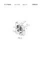
- FIG. 2there is shown a schematic of an enthalpy wheel 52 in accordance with the invention.
- the wheelwhich is shown in a cassette, has a central hub and shaft 54 for support means for supporting the wheel within the cassette and a cylindrical outer casing 56. Other support means may be used. Further, the wheel may have radial spokes extending from hub 54 to outer casting 56.
- wheel 52is shown divided into two parts, 58 and 60. An exhaust air stream is shown exiting through part 58 and air or inlet stream is shown flowing through part 60 countercurrent to the exhaust stream. Wheel 52 transfers both latent and sensible heat energy from the exhaust stream from a room or building or the like to the intake stream to the room from a fresh air supply stream.
- the enthalpy wheeloperates to cool the warm make-up air. That is, the enthalpy wheel absorbs heat from the make-up air and transfers or exchanges the heat in the make-up air to the exhaust stream of air.
- the mediais fabricated by providing alternating layers of flat and corrugated adsorbent paper or desiccant paper that is positioned to provide a multiplicity of open-ended passages parallel to the axis of rotation to permit air to flow therethrough.
- the mediais formed by winding a web of corrugated adsorbent paper or desiccant paper (having a flat sheet of paperboard bonded to one side) around hub 54 until a multi-layered media is built up that extends to outer casing 56.
- the corrugated adsorbent or desiccant paper having one side flatis made by bonding or positioning a flat strip of paperboard over a corrugated strip of desiccant paper.
- the width of the stripdetermines the width of the wheel and the edges of the paperboard forms the faces of the wheel. It should be understood other fabrication techniques that form passages, e.g., honeycomb-shaped passages and the like, may be used, all of which are contemplated within the purview of the invention.
- corrugated strip of desiccant papermay be bonded to a flat strip of metal such as copper or aluminum.
- metal coated with an adsorbentcan be corrupted and wrapped or a metal corrugated or honeycomb shape can be subsequently coated with adsorbent.
- the inventioncan be a monolith of adsorbent or total heat energy and moisture exchange media and an airstream for conditioning or regeneration may be directed alternately between different parts of the media.
- the desiccant or adsorbent paperis described having the desiccant or adsorbent incorporated therein during fabrication of the paper, the paper may be formed and desiccant or adsorbent coated thereon. Or, a combination of desiccant or adsorbent incorporation during paper making and coating with desiccant or adsorbent thereafter may be used.
- the improved desiccant paper in accordance with the inventionis comprised of desiccant or adsorbent, fibrous material and optional binders.
- the desiccantcan be any material capable of efficiently adsorbing moisture from an air stream and capable of efficiently desorbing said moisture to a counter flowing air stream.
- the desiccantcan comprise the use of finely powdered solid, crystalline compounds capable of adsorbing and desorbing moisture from or to an air stream.
- adsorbantsare silica gels, activated aluminas and molecular sieves or zeolites and the like and mixtures of these compounds.
- Other compounds that may be usedare halogenated compounds such as halogen salts including chloride, bromide and fluoride salts, for example.
- the preferred desiccantsare zeolites.
- the zeolitescan be natural crystalline zeolites such as stilbite or synthetic crystalline alumino-silicates referred to as molecular sieves. These materials are activated for adsorption by removing physically adsorbed water from openings in their molecular structure. Further, crystalline zeolites are preferred desiccants over alumina and silica gel because they exhibit less hysteresis during desorption which provides a more efficient moisture exchange between exit and intake air streams.
- zeolitesare preferred desiccant material over activated aluminas and silica gels because activated aluminas and silica gels have a wide pore size distribution, 8 ⁇ to 70 ⁇ for activated aluminas and 8 ⁇ to 100 ⁇ for silica gels.
- the large pores in the structurecan retain airborne contaminants, some of which may impart odor, and these compounds can be desorbed into the make-up air stream returning the contaminants and odors to the building. Thus, purification of air in the building has been compromised.
- the silica and aluminacan be combined with the zeolite, depending on the shape of the isotherm desired.
- synthetic zeolitesare preferred over natural zeolites because the natural-occurring zeolites can have a broader pore size distribution.
- Synthetic zeolitesinclude zeolites A, D, L, R, S, T, X and Y.
- Zeolite Ais a crystalline zeolite having the general formula:
- zeolitic molecular sievesgenerally known in the art as 4A molecular sieves have a pore diameter of about 4 ⁇ and have an alumino silicate crystalline structure A with sodium cations.
- 3A sieveshave an alumino silicate structure A with sodium and potassium cations.
- most of the sodium cations in a 4A molecular sieveare substituted with potassium cations which results in most of the pores in a 3A molecular sieve being 3 ⁇ in diameter.
- 5A molecular sievesmost of the sodium cations in a 4A molecular sieve are substituted with calcium cation and most of the pores in the 5A molecular sieve have about a 5 ⁇ diameter.
- Zeolite Xfor example, has an ideal composition given by:
- Zeolites X and Yhave topologically similar aluminosilicate framework structures, although they are distinct zeolite species with characteristic differences.
- the chemical compositions of zeolites X and Yare related to the synthesis method.
- the zeolitesare distinguished on the basis of chemical composition, structure and their related physical and chemical properties. Differences are found in the cation composition and distribution, the Si/Al ratio and possible Si-Al ordering in tetrahedral sites.
- the Si/Al ratio for a zeolite Xis between 1 and 1.5 whereas it is greater than 1.5 for a Y zeolite.
- Zeolites HY and USYmay be obtained from NaY zeolites by different schemes: thermal decomposition of NH 4 + , hydrogen ion exchange, hydrolysis of a zeolite containing multivalent cations during dehydration.
- zeoliteor “molecular sieve” as used herein is meant to include aluminosilicates, aluminophosphates, silica aluminophosphates, silicates and titanium aluminosilicates.
- suitable molecular sievesinclude 3A, 4A, 5A, 13X, NaY, HY and USY with 3A and 4A molecular sieves being preferred.
- Desiccant suitable for use in the present inventioncan have a particle size ranging from 0.1 to 50 ⁇ m with a preferred particle size being 1 to 4 ⁇ m.
- any type of fibrous materialcan be used that can be fibrillated and thereafter formed by standard paper-making processes into adsorbent paper or desiccant paper having adsorbent or desiccant contained therein.
- fibersinclude wood pulp, e.g., cellulosic fibers, and synthetic fibers and mixtures thereof.
- Inorganic fiberssuch as glass or metal fibers and rock wool, etc., are not particularly suitable but may be used in conjunction with fibrillated organic fibers. That is, non-fibrillated, inorganic and organic fibers may be used in conjunction with the fibrillated fibers.
- the amount of fibrillated and non-fibrillated fiberscan be adjusted to suit the particular need.
- fibrillated fiber as used hereinis meant fiber shafts which are split at their ends to form fibrils, i.e., fine fibers or filaments much finer than the fiber shafts.
- fibrillated, synthetic organic fibers useful in the inventioninclude polymeric fibers selected from the group consisting of high-density polyethylenes, high-density polypropylenes, aromatic polyamides (aramids), polystyrenes, aliphatic polyamides, polyvinyl chlorides, polyesters, nylons, rayons (cellulose acetate), acrylics, acrylonitrile homopolymers, copolymers with halogenated monomers, styrene copolymers, and mixtures of polymers (polypropylene with low-density polyethylene, and high-density polyethylene with polystyrene).
- polymeric fibersselected from the group consisting of high-density polyethylenes, high-density polypropylenes, aromatic polyamides (aramids), polystyrenes, aliphatic polyamides, polyvinyl chlorides, polyesters, nylons, rayons (cellulose acetate), acrylics, acrylonitrile homopolymers, cop
- Synthetic, organic fiberscan be in staple form (chopped yarns), fabricated form (staple that has been refined) or extruded/precipitated form (i.e., polymer dissolved in a solvent precipitated by a nonsolvent or other forming technique).
- the preferred fibers for forming into desiccant paper for use in the present inventionare fibrillated aramid and acrylic fibers.
- the preferred aramid fiberis formed from a long-chain synthetic aromatic polyamide having at least 85% of the amide (--CO--NH--) linkages directly attached to the two aromatic rings.
- a preferred fibrillated aramid fiberis available from E. I. du Pont de Nemours & Company under the designation KEVLAR® 303. In forming fibrillated KEVLAR® material, high shear is applied to KEVLAR® fiber shafts which split at their ends into fibrils to create a tree-like structure.
- the fibrilsinterlock to enhance the paper strength and provide increased area for capturing or securing adsorbent particles. Additional refining of the fibers may be performed to further enhance paper strength.
- KEVLAR®is stable in oxidizing atmospheres up to 450° C.
- Other high-temperature aramid fiberssuch as NOMEX® available from Du Pont, TWARON® available from AKZO Fibers Inc., and TEIJINCONEX® and TECHNORA® available from Teijin Ltd. Japan, are also suitable materials.
- acrylic fiberssuch as fibrillated acrylic fibers available from American Cyanamid under the designation CFF®.
- fiberscan be fibrillated by transferring a slurry of the fibers to a disc or other high shear refiner to split the ends of the chopped fibers or shafts to provide fibrils thereon.
- fibrillated shafts available from the manufacturercan be further refined to increase the degree of fibrillation on the shafts which results in a higher degree of interlocking and consequently stronger desiccant or adsorbent paper.
- the shafts or chopped fiberscan be provided in a length in the range of 1 to 30 mm, and typically in the range of 3 to 15 mm, prior to fibrillation.
- the shafts or chopped fibershave a diameter in the range of 1 to 50, typically 5 to 25 ⁇ m, prior to fibrillation.
- such chopped fibershave fibrils extending therefrom having lengths in the range of 0.5 to 28 mm and preferably in the range of 1 to 10 ⁇ m, and such fibrils typically have a diameter in the range of 0.5 to 40 ⁇ m and preferably in the range of 1 to 10 ⁇ m.
- the fibrillation of the chopped fibersis an important aspect of the present invention. That is, it has been discovered that not only do the fibrillated fibers provide for higher strength in the desiccant or adsorbent paper, but also, it provides for thinner desiccant paper which is very important because of the resultant reduced air flow pressure drop across the media during operation. Further, more efficient adsorption and desorption is achieved. That is, an enthalpy wheel can be made deeper or wider for better adsorption and yet not require higher pressures, thereby raising the efficiency of the wheel. For example, enthalpy wheels formed from the improved desiccant paper can have up to about 25% increase in depth for about the same pressure drop across the wheel.
- fibrillated fibersare important in yet another way. That is, surprisingly, it has been discovered that higher loading of desiccant or adsorbent can be achieved utilizing fibrillated fibers. That is, the fibrils not only provide for thinner and stronger adsorbent paper, but the fibrils provide additional surface area on and in which desiccant or adsorbent can attach or anchor. Thus, compared to non-fibrillated shafts, fibrillated fibers provide for higher loading of desiccant or adsorbent in paper having desiccant or adsorbent dispersed therein without loss in strength of the paper.
- the paper of the present inventioncan be prepared by wet-laying the desiccant and fibrillated fibers into a continuous sheet or web or into a hand sheet. The paper may then be formed into a single-faced corrugated laminate, which is spirally wrapped to make the adsorbent wheel.
- the fibrillated organic fibersprovide highly suitable reinforcement at levels as low as 15 wt. % of the total desiccant paper structure due to their strength and ability to interlock.
- Some desiccant papers of suitable strengthcan be made having less than 10 wt. % fibers with very high sorbent loading when made in accordance with the invention.
- Desiccant or adsorbent paper used in wheels in accordance with the inventioncan comprise 5 to 85 wt. % desiccant or adsorbent, the remainder comprising fibrous material.
- Bindercan be added as needed. For example, if cellulose fibers from wood pulp are used in sufficient quantity, binder does not have to be added. Typical composition ranges can comprise 5 to 70 wt. % desiccant or adsorbent, the remainder comprising fibrous material and binder.
- a typical compositioncomprises about 38 wt. % fibrous material, about 50 wt. % desiccant or adsorbent and about 12 wt. % binder.
- the adsorbent papercan contain 15 to 75 wt. %, typically 30 to 55 wt. %, fibrillated fibers, 1 to 20 wt. %, typically 5 to 15 wt. %, binder with the balance being adsorbent.
- the desiccant or adsorbent paper thus formed containing solid desiccant or adsorbent dispersed therein during the paper manufacturing processesare formed into heat and moisture transfer bodies such as total energy transfer wheels or enthalpy wheels. Additionally, the adsorbent paper can be formed into mass transfer bodies such as adsorbent fillers for contaminants. For example, the desiccant or adsorbent paper can be formed into such wheels by the formation of corrugated paper having the desired thickness and periodicity and bonded to a flat paperboard of similar composition to produce a single-faced corrugated sheet.
- the single-faced corrugated sheetis spirally rolled into a wheel configuration with the passages or channels formed by the corrugations and flat paperboard being parallel to the axial direction of the wheel.
- the paperboardshould be as thin as possible while maintaining strength to minimize the pressure drop across the wheel. Thin paperboard permits the manufacture of smaller channels to provide higher surface area for heat and mass transfer.
- an enthalpy wheelcan be manufactured that provides for improved levels of moisture and heat transfer. Further, the enthalpy wheel can be readily mass produced in a cost effective manner. Conventional paper-making equipment and corrugating equipment can be used for manufacturing.
- FIG. 3The advantages of the present invention are illustrated by modeling a heat recovery and dehumidification system in accordance with the invention as set forth in FIG. 3.
- outdoor airat 95° F., 0.01843 lbs H 2 O/lb of air and a dew point of 74.5° F. was introduced to an enthalpy wheel at 2000 SCFM.
- the air removed from the enthalpy wheelwas reduced to a temperature of 83° F. and contained 0.01477 lbs H 2 O/lb of air.
- the air from the enthalpy wheelwas introduced an evaporator where the temperature and moisture was reduced to 56.2° F. at 0.00960 lbs H 2 O/lb of air.
- the air from the evaporatorwas introduced to a refrigerant subcooling coil where the temperature was raised to 66.2° F. while the humidity was maintained at 0.00960 lbs H 2 O/lb of air.
- the state pointsare provided in Table 1.
- About 5.3 tons of coolingresult from the use of the enthalpy wheel providing a total of 12.7 tons of cooling when treating 2000 SCFM of outdoor air using a 7.5 ton compressor.
- the conditioned aircan be supplied to a conditioned space at 66.2° F., at a humidity level of 0.0096 lbs H 2 O/lb of air which is well below building neutral conditions for both temperature and moisture content aiding in maintaining a low humidity in the conditioned space.
- the energy efficiency ratio (EER)which is the ratio of cooling capacity (BTU/h) to electricity used (watts) of the modeled unit including power required for blowers is 14.9 BTU/h/W.
- inlet airwas introduced to an evaporator at 1300 SCFM, 95° F. and 0.01843 lbs H 2 O/lb of air.
- No enthalpy wheel or subcoolingwas used in this model.
- the airwas cooled to 62° F. at 0.01188 lbs H 2 O/lb of air, as shown in FIG. 5.
- the state points for this systemare provided in Table 3.
- the supply or conditioned airwas colder but the moisture level was above building neutral which is max. 0.011 lbs H 2 O/lb of air.
- the high moistureplaces an additional load on the air-conditioning system. Only 7.5 tons of cooling was accomplished on 1300 SCFM of air to provide an EER of 9.9.
- the system using the enthalpy wheel and refrigerant subcoolingwas able to condition 54% more air to a more desirable condition.
Landscapes
- Engineering & Computer Science (AREA)
- Chemical & Material Sciences (AREA)
- Combustion & Propulsion (AREA)
- Mechanical Engineering (AREA)
- General Engineering & Computer Science (AREA)
- General Chemical & Material Sciences (AREA)
- Analytical Chemistry (AREA)
- Oil, Petroleum & Natural Gas (AREA)
- Chemical Kinetics & Catalysis (AREA)
- Life Sciences & Earth Sciences (AREA)
- Sustainable Development (AREA)
- Central Air Conditioning (AREA)
- Drying Of Gases (AREA)
Abstract
Description
1±0.2M.sub.2-n O:Al.sub.2 O.sub.3 :1.85±0.5SiO.sub.2 :yH.sub.2 O
Na.sub.86 (AlO.sub.2).sub.86.(SiO.sub.2).sub.108 !.264H.sub.2 O
TABLE 1 __________________________________________________________________________ Dew Flow Flow Mass Temp. Pt. Rate Rate Flow W W RH Enthalpy °F. °F. cfm scfm lb/min lb/lb gr/lb % BTU/lb __________________________________________________________________________1 Outdoor 95.0 74.5 2170 2000 150.7 0.01843 129.0 51.8 43.13 2 Indoor 75.0 59.9 1654 1600 120.6 0.01100 77.0 59.4 30.04 3 Evaporator 83.0 68.2 2111 2000 150.7 0.01477 103.4 61.0 36.14 Inlet 4 Subcool 56.2 56.2 1990 2000 150.7 0.00960 67.2 100.0 23.90 Coil Inlet 5 Supply 66.2 56.2 2029 2000 150.7 0.00960 67.2 70.2 26.34 __________________________________________________________________________
TABLE 2 __________________________________________________________________________ Dew Flow Flow Mass Temp. Pt. Rate Rate Flow W W RH Enthalpy °F. °F. cfm scfm lb/min lb/lb gr/lb % BTU/lb __________________________________________________________________________1 Outdoor 95.0 74.5 1411 1300 98.0 0.01843 129.0 51.8 43.13 2 Indoor 75.0 59.9 1654 1600 120.6 0.01100 77.0 59.4 30.04 3 Evaporator 95.0 74.5 1411 1300 98.0 0.01843 129.0 51.8 43.13 Inlet 4 Subcool 56.8 56.8 1296 1300 98.0 0.00982 68.8 100.0 24.30 Coil Inlet 5 Supply 66.8 56.8 1321 1300 98.0 0.00982 68.8 70.2 26.74 __________________________________________________________________________
TABLE 3 __________________________________________________________________________ Dew Flow Flow Mass Temp. Pt. Rate Rate Flow W W RH Enthalpy °F. °F. cfm scfm lb/min lb/lb gr/lb % BTU/lb __________________________________________________________________________1 Outdoor 95.0 74.5 1411 1300 98.0 0.01843 129.0 51.8 43.13 2 Indoor 75.0 59.9 1654 1600 120.6 0.01100 77.0 59.4 30.04 3 Evaporator 95.0 74.5 1411 1300 98.0 0.01843 129.0 51.8 43.113 Inlet 4 Subcool 62.0 62.0 1313 1300 98.0 0.01188 83.2 100.0 27.82 Coil Inlet 5 Supply 62.0 62.0 1313 1300 98.0 0.01188 83.2 100.0 27.82 __________________________________________________________________________
Claims (33)
Priority Applications (1)
| Application Number | Priority Date | Filing Date | Title |
|---|---|---|---|
| US08/682,131US5826434A (en) | 1995-11-09 | 1996-07-17 | High efficiency outdoor air conditioning system |
Applications Claiming Priority (2)
| Application Number | Priority Date | Filing Date | Title |
|---|---|---|---|
| US641495P | 1995-11-09 | 1995-11-09 | |
| US08/682,131US5826434A (en) | 1995-11-09 | 1996-07-17 | High efficiency outdoor air conditioning system |
Publications (1)
| Publication Number | Publication Date |
|---|---|
| US5826434Atrue US5826434A (en) | 1998-10-27 |
Family
ID=26675599
Family Applications (1)
| Application Number | Title | Priority Date | Filing Date |
|---|---|---|---|
| US08/682,131Expired - LifetimeUS5826434A (en) | 1995-11-09 | 1996-07-17 | High efficiency outdoor air conditioning system |
Country Status (1)
| Country | Link |
|---|---|
| US (1) | US5826434A (en) |
Cited By (63)
| Publication number | Priority date | Publication date | Assignee | Title |
|---|---|---|---|---|
| WO2001020701A1 (en)* | 1999-09-14 | 2001-03-22 | International Fuel Cells, Llc | Fine pore enthalpy exchange barrier for a fuel cell power plant |
| US6355091B1 (en) | 2000-03-06 | 2002-03-12 | Honeywell International Inc. | Ventilating dehumidifying system using a wheel for both heat recovery and dehumidification |
| EP1164339A4 (en)* | 1999-03-05 | 2002-04-10 | Daikin Ind Ltd | AIR CONDITIONER |
| US6475652B2 (en)* | 1999-09-14 | 2002-11-05 | Utc Fuel Cells, Llc | Fine pore enthalpy exchange barrier for a fuel cell power plant |
| US6575228B1 (en) | 2000-03-06 | 2003-06-10 | Mississippi State Research And Technology Corporation | Ventilating dehumidifying system |
| WO2003067156A3 (en)* | 2002-02-06 | 2004-02-19 | Jose Moratalla | Desiccant dehumidification system |
| US6751964B2 (en) | 2002-06-28 | 2004-06-22 | John C. Fischer | Desiccant-based dehumidification system and method |
| US20040134210A1 (en)* | 2001-07-18 | 2004-07-15 | Tomohiro Yabu | Adsorption element and air conditioning device |
| US20040216482A1 (en)* | 2003-04-29 | 2004-11-04 | Derossett John M. | Refrigerator having a coil cooling device for increasing efficiency and method therefor |
| US20050268633A1 (en)* | 2004-06-08 | 2005-12-08 | Smith Douglas M | Sorption cooling systems, their use in automotive cooling applications and methods relating to the same |
| US20080102744A1 (en)* | 2006-10-31 | 2008-05-01 | Everdry Marketing & Management, Inc. | Ventilation system |
| US20080276640A1 (en)* | 2007-05-10 | 2008-11-13 | Mohinder Singh Bhatti | Evaporative cooler and desiccant assisted vapor compression AC system |
| US7559207B2 (en) | 2005-06-23 | 2009-07-14 | York International Corporation | Method for refrigerant pressure control in refrigeration systems |
| US20100200068A1 (en)* | 2009-02-06 | 2010-08-12 | Thermotech Enterprises, Inc. | Dynamic purge system for a heat recovery wheel |
| US7845185B2 (en) | 2004-12-29 | 2010-12-07 | York International Corporation | Method and apparatus for dehumidification |
| US20100307175A1 (en)* | 2008-02-14 | 2010-12-09 | Peter Teige | Energy recovery enhanced condenser reactivated desiccant refrigerant dehumidifier |
| US7886986B2 (en) | 2006-11-08 | 2011-02-15 | Semco Inc. | Building, ventilation system, and recovery device control |
| US20120028560A1 (en)* | 2010-07-29 | 2012-02-02 | Zivota Nikolic | Fresh Air Recovery System |
| US20130186593A1 (en)* | 2012-01-20 | 2013-07-25 | Synairco, Inc. | Split-air flow cooling and dehumidification system |
| US20130248147A1 (en)* | 2012-03-22 | 2013-09-26 | Venmar Ces, Inc. | System and method for conditioning air in an enclosed structure |
| US8915092B2 (en) | 2011-01-19 | 2014-12-23 | Venmar Ces, Inc. | Heat pump system having a pre-processing module |
| WO2014208083A1 (en)* | 2013-06-28 | 2014-12-31 | ダイキン工業株式会社 | Dehumidification device and dehumidification system |
| US8943848B2 (en) | 2010-06-16 | 2015-02-03 | Reznor Llc | Integrated ventilation unit |
| US9109808B2 (en) | 2013-03-13 | 2015-08-18 | Venmar Ces, Inc. | Variable desiccant control energy exchange system and method |
| DE10103150B4 (en)* | 2001-01-24 | 2015-12-10 | Stiebel Eltron Gmbh & Co. Kg | ventilation |
| US9234665B2 (en) | 2010-06-24 | 2016-01-12 | Nortek Air Solutions Canada, Inc. | Liquid-to-air membrane energy exchanger |
| CN106895520A (en)* | 2017-02-15 | 2017-06-27 | 南京腾亚睿尼环境科技有限公司 | A kind of air source heat pump constant temperature, constant humidity, permanent oxygen air-conditioner set |
| US9772124B2 (en) | 2013-03-13 | 2017-09-26 | Nortek Air Solutions Canada, Inc. | Heat pump defrosting system and method |
| US9810439B2 (en) | 2011-09-02 | 2017-11-07 | Nortek Air Solutions Canada, Inc. | Energy exchange system for conditioning air in an enclosed structure |
| US9816760B2 (en) | 2012-08-24 | 2017-11-14 | Nortek Air Solutions Canada, Inc. | Liquid panel assembly |
| EP2413049A3 (en)* | 2010-07-27 | 2017-12-27 | Mitsubishi Heavy Industries Thermal Systems, Ltd. | Desiccant air-conditioning system |
| US9885486B2 (en) | 2010-08-27 | 2018-02-06 | Nortek Air Solutions Canada, Inc. | Heat pump humidifier and dehumidifier system and method |
| US10274210B2 (en) | 2010-08-27 | 2019-04-30 | Nortek Air Solutions Canada, Inc. | Heat pump humidifier and dehumidifier system and method |
| US10352628B2 (en) | 2013-03-14 | 2019-07-16 | Nortek Air Solutions Canada, Inc. | Membrane-integrated energy exchange assembly |
| CN110567058A (en)* | 2019-09-24 | 2019-12-13 | 王永红 | Rotating wheel dehumidification fresh air cabinet machine |
| US10584884B2 (en) | 2013-03-15 | 2020-03-10 | Nortek Air Solutions Canada, Inc. | Control system and method for a liquid desiccant air delivery system |
| US10653042B2 (en) | 2016-11-11 | 2020-05-12 | Stulz Air Technology Systems, Inc. | Dual mass cooling precision system |
| US10712024B2 (en) | 2014-08-19 | 2020-07-14 | Nortek Air Solutions Canada, Inc. | Liquid to air membrane energy exchangers |
| US10782045B2 (en) | 2015-05-15 | 2020-09-22 | Nortek Air Solutions Canada, Inc. | Systems and methods for managing conditions in enclosed space |
| US10808951B2 (en) | 2015-05-15 | 2020-10-20 | Nortek Air Solutions Canada, Inc. | Systems and methods for providing cooling to a heat load |
| US10962252B2 (en) | 2015-06-26 | 2021-03-30 | Nortek Air Solutions Canada, Inc. | Three-fluid liquid to air membrane energy exchanger |
| US11092349B2 (en) | 2015-05-15 | 2021-08-17 | Nortek Air Solutions Canada, Inc. | Systems and methods for providing cooling to a heat load |
| DE102020128629A1 (en) | 2020-10-30 | 2022-05-05 | Vaillant Gmbh | Device and method for the combined operation of a heat pump for heating water and a ventilation system |
| US11408681B2 (en) | 2013-03-15 | 2022-08-09 | Nortek Air Solations Canada, Iac. | Evaporative cooling system with liquid-to-air membrane energy exchanger |
| US11414843B2 (en)* | 2019-04-22 | 2022-08-16 | Source Global, PBC | Thermal desiccant systems and methods for generating liquid water |
| US11447407B2 (en) | 2017-07-14 | 2022-09-20 | Source Global, PBC | Systems for controlled treatment of water with ozone and related methods therefor |
| US11555421B2 (en) | 2017-10-06 | 2023-01-17 | Source Global, PBC | Systems for generating water with waste heat and related methods therefor |
| US11607644B2 (en) | 2018-05-11 | 2023-03-21 | Source Global, PBC | Systems for generating water using exogenously generated heat, exogenously generated electricity, and exhaust process fluids and related methods therefor |
| US20230113840A1 (en)* | 2021-10-08 | 2023-04-13 | Source Global, PBC | Systems and methods for water production, treatment, adjustment and storage |
| CN116398950A (en)* | 2023-06-09 | 2023-07-07 | 江苏嘉盛环境设备制造有限公司 | Heating protection connection method for household rotary dehumidifier |
| US11814820B2 (en) | 2021-01-19 | 2023-11-14 | Source Global, PBC | Systems and methods for generating water from air |
| US11859372B2 (en) | 2017-09-05 | 2024-01-02 | Source Global, PBC | Systems and methods to produce liquid water extracted from air |
| US11892193B2 (en) | 2017-04-18 | 2024-02-06 | Nortek Air Solutions Canada, Inc. | Desiccant enhanced evaporative cooling systems and methods |
| US11900226B2 (en) | 2017-12-06 | 2024-02-13 | Source Global, PBC | Systems for constructing hierarchical training data sets for use with machine-learning and related methods therefor |
| US11913903B1 (en) | 2018-10-22 | 2024-02-27 | Source Global, PBC | Systems and methods for testing and measuring compounds |
| US11946232B2 (en) | 2018-10-19 | 2024-04-02 | Source Global, PBC | Systems and methods for generating liquid water using highly efficient techniques that optimize production |
| US11975289B2 (en) | 2016-05-20 | 2024-05-07 | Source Global, PBC | Systems and methods for water extraction control |
| US12021488B2 (en) | 2016-04-07 | 2024-06-25 | Source Global, PBC | Solar thermal unit |
| US12276091B2 (en) | 2017-09-05 | 2025-04-15 | Source Global, PBC | Systems and methods for managing production and distribution of liquid water extracted from air |
| US12312265B2 (en) | 2020-10-27 | 2025-05-27 | Source Global, PBC | Systems and methods for water treatment and storage |
| US12385654B2 (en) | 2017-04-18 | 2025-08-12 | Nortek Air Solutions Canada, Inc. | Systems and methods for managing conditions in enclosed space |
| USD1094637S1 (en) | 2021-04-21 | 2025-09-23 | Source Global, PBC | Water generation panel |
| US12442558B2 (en) | 2023-09-29 | 2025-10-14 | Nortek Air Solutions Canada, Inc. | Using liquid to air membrane energy exchanger for liquid cooling |
Citations (48)
| Publication number | Priority date | Publication date | Assignee | Title |
|---|---|---|---|---|
| US2968165A (en)* | 1955-12-22 | 1961-01-17 | Norback Per Gunnar | Air conditioning method and apparatus |
| US3009684A (en)* | 1954-10-26 | 1961-11-21 | Munters Carl Georg | Apparatus and method of conditioning the stream of incoming air by the thermodynamic exchange with separate streams of other air |
| US3144901A (en)* | 1960-05-13 | 1964-08-18 | Lizenzia A G | Movable air conditioning apparatus |
| US3470708A (en)* | 1967-10-12 | 1969-10-07 | Inst Gas Technology | Solid-adsorbent air-conditioning device |
| US3498078A (en)* | 1968-08-20 | 1970-03-03 | Addison Products Co | Split unit for both double-hung and sliding windows |
| US3576114A (en)* | 1969-06-18 | 1971-04-27 | Addison Products Co | Window air-conditioning unit |
| US3663306A (en)* | 1968-11-06 | 1972-05-16 | Sanders Nuclear Corp | High pressure resistant compact housing structure |
| US3791369A (en)* | 1972-08-08 | 1974-02-12 | Donbar Dev Corp | Rotary heat exchanger |
| US3813893A (en)* | 1972-10-30 | 1974-06-04 | Addison Prod Co | Refrigeration system charging kit |
| US3828528A (en)* | 1971-02-23 | 1974-08-13 | Gas Dev Corp | Adiabatic saturation cooling machine |
| US3835921A (en)* | 1973-02-01 | 1974-09-17 | Donbar Dev Corp | Rotatable heat exchanger |
| US3913346A (en)* | 1974-05-30 | 1975-10-21 | Dunham Bush Inc | Liquid refrigerant injection system for hermetic electric motor driven helical screw compressor |
| US4042018A (en)* | 1975-09-29 | 1977-08-16 | Des Champs Laboratories Incorporated | Packaging for heat exchangers |
| US4134743A (en)* | 1970-03-31 | 1979-01-16 | Gas Developments Corporation | Desiccant apparatus and method |
| US4180985A (en)* | 1977-12-01 | 1980-01-01 | Northrup, Incorporated | Air conditioning system with regeneratable desiccant bed |
| US4207749A (en)* | 1977-08-29 | 1980-06-17 | Carrier Corporation | Thermal economized refrigeration system |
| US4219012A (en)* | 1976-03-05 | 1980-08-26 | Addison Products Company | Solar heating with air transfer |
| US4304100A (en)* | 1979-09-24 | 1981-12-08 | Tyler Refrigeration Corporation | Energy saving refrigeration system with mechanical subcooling |
| US4321800A (en)* | 1978-08-17 | 1982-03-30 | Addison Products Company | Dehumidifier structure |
| US4321803A (en)* | 1979-11-23 | 1982-03-30 | Addison Products Company | Multiple air passage condenser |
| US4484450A (en)* | 1982-09-30 | 1984-11-27 | Niagara Frontier Services | High efficiency refrigeration system |
| US4621505A (en)* | 1985-08-01 | 1986-11-11 | Hussmann Corporation | Flow-through surge receiver |
| US4631926A (en)* | 1985-08-23 | 1986-12-30 | Goldshtein Lev I | Method of obtaining low temperatures and apparatus for implementing the same |
| US4711094A (en)* | 1986-11-12 | 1987-12-08 | Hussmann Corporation | Reverse cycle heat reclaim coil and subcooling method |
| US4769053A (en)* | 1987-03-26 | 1988-09-06 | Semco Mfg., Inc. | High efficiency sensible and latent heat exchange media with selected transfer for a total energy recovery wheel |
| US4924681A (en)* | 1989-05-18 | 1990-05-15 | Martin B. DeVit | Combined heat pump and domestic water heating circuit |
| US4959970A (en)* | 1987-05-12 | 1990-10-02 | Gershon Meckler | Air conditioning apparatus |
| US4984433A (en)* | 1989-09-26 | 1991-01-15 | Worthington Donald J | Air conditioning apparatus having variable sensible heat ratio |
| US5024063A (en)* | 1990-05-11 | 1991-06-18 | Erickson Donald C | Branched gax absorption vapor compressor |
| US5040375A (en)* | 1987-02-12 | 1991-08-20 | Von Dobeln Wilhelm E G | Method and device for conditioning of a gas |
| US5079929A (en)* | 1979-07-31 | 1992-01-14 | Alsenz Richard H | Multi-stage refrigeration apparatus and method |
| US5115644A (en)* | 1979-07-31 | 1992-05-26 | Alsenz Richard H | Method and apparatus for condensing and subcooling refrigerant |
| US5174130A (en)* | 1990-03-14 | 1992-12-29 | Sonic Compressor Systems, Inc. | Refrigeration system having standing wave compressor |
| US5179998A (en)* | 1992-01-24 | 1993-01-19 | Champs Nicholas H Des | Heat recovery ventilating dehumidifier |
| US5181387A (en)* | 1985-04-03 | 1993-01-26 | Gershon Meckler | Air conditioning apparatus |
| JPH05157282A (en)* | 1991-12-05 | 1993-06-22 | Fujita Corp | Air conditioning outside air treatment system for buildings |
| US5263341A (en)* | 1990-03-14 | 1993-11-23 | Sonic Compressor Systems, Inc. | Compression-evaporation method using standing acoustic wave |
| US5303771A (en)* | 1992-12-18 | 1994-04-19 | Des Champs Laboratories Incorporated | Double cross counterflow plate type heat exchanger |
| US5333677A (en)* | 1974-04-02 | 1994-08-02 | Stephen Molivadas | Evacuated two-phase head-transfer systems |
| US5353606A (en)* | 1991-10-15 | 1994-10-11 | Yoho Robert W | Desiccant multi-fuel hot air/water air conditioning unit |
| US5372182A (en)* | 1993-05-24 | 1994-12-13 | Gore; Thomas L. | Modular regenerator pre-conditioner air system |
| US5373704A (en)* | 1990-04-17 | 1994-12-20 | Arthur D. Little, Inc. | Desiccant dehumidifier |
| US5386709A (en)* | 1992-12-10 | 1995-02-07 | Baltimore Aircoil Company, Inc. | Subcooling and proportional control of subcooling of liquid refrigerant circuits with thermal storage or low temperature reservoirs |
| US5419155A (en)* | 1993-03-31 | 1995-05-30 | American Standard Inc. | Cooling of compressor lubricant in a refrigeration system condenser |
| US5423187A (en)* | 1993-11-30 | 1995-06-13 | Bernard Fournier | Rooftop air conditioning unit and method of modification with a rotary regenerative heat exchanger |
| US5438846A (en)* | 1994-05-19 | 1995-08-08 | Datta; Chander | Heat-pump with sub-cooling heat exchanger |
| US5448895A (en)* | 1993-01-08 | 1995-09-12 | Engelhard/Icc | Hybrid heat pump and desiccant space conditioning system and control method |
| US5564281A (en)* | 1993-01-08 | 1996-10-15 | Engelhard/Icc | Method of operating hybrid air-conditioning system with fast condensing start-up |
- 1996
- 1996-07-17USUS08/682,131patent/US5826434A/ennot_activeExpired - Lifetime
Patent Citations (48)
| Publication number | Priority date | Publication date | Assignee | Title |
|---|---|---|---|---|
| US3009684A (en)* | 1954-10-26 | 1961-11-21 | Munters Carl Georg | Apparatus and method of conditioning the stream of incoming air by the thermodynamic exchange with separate streams of other air |
| US2968165A (en)* | 1955-12-22 | 1961-01-17 | Norback Per Gunnar | Air conditioning method and apparatus |
| US3144901A (en)* | 1960-05-13 | 1964-08-18 | Lizenzia A G | Movable air conditioning apparatus |
| US3470708A (en)* | 1967-10-12 | 1969-10-07 | Inst Gas Technology | Solid-adsorbent air-conditioning device |
| US3498078A (en)* | 1968-08-20 | 1970-03-03 | Addison Products Co | Split unit for both double-hung and sliding windows |
| US3663306A (en)* | 1968-11-06 | 1972-05-16 | Sanders Nuclear Corp | High pressure resistant compact housing structure |
| US3576114A (en)* | 1969-06-18 | 1971-04-27 | Addison Products Co | Window air-conditioning unit |
| US4134743A (en)* | 1970-03-31 | 1979-01-16 | Gas Developments Corporation | Desiccant apparatus and method |
| US3828528A (en)* | 1971-02-23 | 1974-08-13 | Gas Dev Corp | Adiabatic saturation cooling machine |
| US3791369A (en)* | 1972-08-08 | 1974-02-12 | Donbar Dev Corp | Rotary heat exchanger |
| US3813893A (en)* | 1972-10-30 | 1974-06-04 | Addison Prod Co | Refrigeration system charging kit |
| US3835921A (en)* | 1973-02-01 | 1974-09-17 | Donbar Dev Corp | Rotatable heat exchanger |
| US5333677A (en)* | 1974-04-02 | 1994-08-02 | Stephen Molivadas | Evacuated two-phase head-transfer systems |
| US3913346A (en)* | 1974-05-30 | 1975-10-21 | Dunham Bush Inc | Liquid refrigerant injection system for hermetic electric motor driven helical screw compressor |
| US4042018A (en)* | 1975-09-29 | 1977-08-16 | Des Champs Laboratories Incorporated | Packaging for heat exchangers |
| US4219012A (en)* | 1976-03-05 | 1980-08-26 | Addison Products Company | Solar heating with air transfer |
| US4207749A (en)* | 1977-08-29 | 1980-06-17 | Carrier Corporation | Thermal economized refrigeration system |
| US4180985A (en)* | 1977-12-01 | 1980-01-01 | Northrup, Incorporated | Air conditioning system with regeneratable desiccant bed |
| US4321800A (en)* | 1978-08-17 | 1982-03-30 | Addison Products Company | Dehumidifier structure |
| US5115644A (en)* | 1979-07-31 | 1992-05-26 | Alsenz Richard H | Method and apparatus for condensing and subcooling refrigerant |
| US5079929A (en)* | 1979-07-31 | 1992-01-14 | Alsenz Richard H | Multi-stage refrigeration apparatus and method |
| US4304100A (en)* | 1979-09-24 | 1981-12-08 | Tyler Refrigeration Corporation | Energy saving refrigeration system with mechanical subcooling |
| US4321803A (en)* | 1979-11-23 | 1982-03-30 | Addison Products Company | Multiple air passage condenser |
| US4484450A (en)* | 1982-09-30 | 1984-11-27 | Niagara Frontier Services | High efficiency refrigeration system |
| US5181387A (en)* | 1985-04-03 | 1993-01-26 | Gershon Meckler | Air conditioning apparatus |
| US4621505A (en)* | 1985-08-01 | 1986-11-11 | Hussmann Corporation | Flow-through surge receiver |
| US4631926A (en)* | 1985-08-23 | 1986-12-30 | Goldshtein Lev I | Method of obtaining low temperatures and apparatus for implementing the same |
| US4711094A (en)* | 1986-11-12 | 1987-12-08 | Hussmann Corporation | Reverse cycle heat reclaim coil and subcooling method |
| US5040375A (en)* | 1987-02-12 | 1991-08-20 | Von Dobeln Wilhelm E G | Method and device for conditioning of a gas |
| US4769053A (en)* | 1987-03-26 | 1988-09-06 | Semco Mfg., Inc. | High efficiency sensible and latent heat exchange media with selected transfer for a total energy recovery wheel |
| US4959970A (en)* | 1987-05-12 | 1990-10-02 | Gershon Meckler | Air conditioning apparatus |
| US4924681A (en)* | 1989-05-18 | 1990-05-15 | Martin B. DeVit | Combined heat pump and domestic water heating circuit |
| US4984433A (en)* | 1989-09-26 | 1991-01-15 | Worthington Donald J | Air conditioning apparatus having variable sensible heat ratio |
| US5174130A (en)* | 1990-03-14 | 1992-12-29 | Sonic Compressor Systems, Inc. | Refrigeration system having standing wave compressor |
| US5263341A (en)* | 1990-03-14 | 1993-11-23 | Sonic Compressor Systems, Inc. | Compression-evaporation method using standing acoustic wave |
| US5373704A (en)* | 1990-04-17 | 1994-12-20 | Arthur D. Little, Inc. | Desiccant dehumidifier |
| US5024063A (en)* | 1990-05-11 | 1991-06-18 | Erickson Donald C | Branched gax absorption vapor compressor |
| US5353606A (en)* | 1991-10-15 | 1994-10-11 | Yoho Robert W | Desiccant multi-fuel hot air/water air conditioning unit |
| JPH05157282A (en)* | 1991-12-05 | 1993-06-22 | Fujita Corp | Air conditioning outside air treatment system for buildings |
| US5179998A (en)* | 1992-01-24 | 1993-01-19 | Champs Nicholas H Des | Heat recovery ventilating dehumidifier |
| US5386709A (en)* | 1992-12-10 | 1995-02-07 | Baltimore Aircoil Company, Inc. | Subcooling and proportional control of subcooling of liquid refrigerant circuits with thermal storage or low temperature reservoirs |
| US5303771A (en)* | 1992-12-18 | 1994-04-19 | Des Champs Laboratories Incorporated | Double cross counterflow plate type heat exchanger |
| US5448895A (en)* | 1993-01-08 | 1995-09-12 | Engelhard/Icc | Hybrid heat pump and desiccant space conditioning system and control method |
| US5564281A (en)* | 1993-01-08 | 1996-10-15 | Engelhard/Icc | Method of operating hybrid air-conditioning system with fast condensing start-up |
| US5419155A (en)* | 1993-03-31 | 1995-05-30 | American Standard Inc. | Cooling of compressor lubricant in a refrigeration system condenser |
| US5372182A (en)* | 1993-05-24 | 1994-12-13 | Gore; Thomas L. | Modular regenerator pre-conditioner air system |
| US5423187A (en)* | 1993-11-30 | 1995-06-13 | Bernard Fournier | Rooftop air conditioning unit and method of modification with a rotary regenerative heat exchanger |
| US5438846A (en)* | 1994-05-19 | 1995-08-08 | Datta; Chander | Heat-pump with sub-cooling heat exchanger |
Cited By (88)
| Publication number | Priority date | Publication date | Assignee | Title |
|---|---|---|---|---|
| US6619064B1 (en) | 1999-03-05 | 2003-09-16 | Daikin Industries, Ltd. | Air conditioning system |
| EP1164339A4 (en)* | 1999-03-05 | 2002-04-10 | Daikin Ind Ltd | AIR CONDITIONER |
| US6475652B2 (en)* | 1999-09-14 | 2002-11-05 | Utc Fuel Cells, Llc | Fine pore enthalpy exchange barrier for a fuel cell power plant |
| US6274259B1 (en)* | 1999-09-14 | 2001-08-14 | International Fuel Cells Llc | Fine pore enthalpy exchange barrier |
| WO2001020701A1 (en)* | 1999-09-14 | 2001-03-22 | International Fuel Cells, Llc | Fine pore enthalpy exchange barrier for a fuel cell power plant |
| US6355091B1 (en) | 2000-03-06 | 2002-03-12 | Honeywell International Inc. | Ventilating dehumidifying system using a wheel for both heat recovery and dehumidification |
| US6575228B1 (en) | 2000-03-06 | 2003-06-10 | Mississippi State Research And Technology Corporation | Ventilating dehumidifying system |
| DE10103150B4 (en)* | 2001-01-24 | 2015-12-10 | Stiebel Eltron Gmbh & Co. Kg | ventilation |
| US6978635B2 (en)* | 2001-07-18 | 2005-12-27 | Daikin Industries Ltd. | Adsorption element and air conditioning device |
| US20040134210A1 (en)* | 2001-07-18 | 2004-07-15 | Tomohiro Yabu | Adsorption element and air conditioning device |
| WO2003067156A3 (en)* | 2002-02-06 | 2004-02-19 | Jose Moratalla | Desiccant dehumidification system |
| US6751964B2 (en) | 2002-06-28 | 2004-06-22 | John C. Fischer | Desiccant-based dehumidification system and method |
| US20040216482A1 (en)* | 2003-04-29 | 2004-11-04 | Derossett John M. | Refrigerator having a coil cooling device for increasing efficiency and method therefor |
| US20050268633A1 (en)* | 2004-06-08 | 2005-12-08 | Smith Douglas M | Sorption cooling systems, their use in automotive cooling applications and methods relating to the same |
| US7143589B2 (en) | 2004-06-08 | 2006-12-05 | Nanopore, Inc. | Sorption cooling systems, their use in automotive cooling applications and methods relating to the same |
| US7845185B2 (en) | 2004-12-29 | 2010-12-07 | York International Corporation | Method and apparatus for dehumidification |
| US7559207B2 (en) | 2005-06-23 | 2009-07-14 | York International Corporation | Method for refrigerant pressure control in refrigeration systems |
| US20080102744A1 (en)* | 2006-10-31 | 2008-05-01 | Everdry Marketing & Management, Inc. | Ventilation system |
| US7886986B2 (en) | 2006-11-08 | 2011-02-15 | Semco Inc. | Building, ventilation system, and recovery device control |
| US20080276640A1 (en)* | 2007-05-10 | 2008-11-13 | Mohinder Singh Bhatti | Evaporative cooler and desiccant assisted vapor compression AC system |
| US8631661B2 (en)* | 2008-02-14 | 2014-01-21 | Munters Corporation | Energy recovery enhanced condenser reactivated desiccant refrigerant dehumidifier |
| US20100307175A1 (en)* | 2008-02-14 | 2010-12-09 | Peter Teige | Energy recovery enhanced condenser reactivated desiccant refrigerant dehumidifier |
| US8584733B2 (en)* | 2009-02-06 | 2013-11-19 | Thermotech Enterprises, Inc. | Dynamic purge system for a heat recovery wheel |
| US20100200068A1 (en)* | 2009-02-06 | 2010-08-12 | Thermotech Enterprises, Inc. | Dynamic purge system for a heat recovery wheel |
| US9816724B2 (en) | 2010-06-16 | 2017-11-14 | Reznor Llc | Integrated ventilation unit |
| US8943848B2 (en) | 2010-06-16 | 2015-02-03 | Reznor Llc | Integrated ventilation unit |
| US12111072B2 (en) | 2010-06-24 | 2024-10-08 | Nortek Air Solutions Canada, Inc. | Liquid-to-air membrane energy exchanger |
| US9234665B2 (en) | 2010-06-24 | 2016-01-12 | Nortek Air Solutions Canada, Inc. | Liquid-to-air membrane energy exchanger |
| EP2413049A3 (en)* | 2010-07-27 | 2017-12-27 | Mitsubishi Heavy Industries Thermal Systems, Ltd. | Desiccant air-conditioning system |
| US20120028560A1 (en)* | 2010-07-29 | 2012-02-02 | Zivota Nikolic | Fresh Air Recovery System |
| US10274210B2 (en) | 2010-08-27 | 2019-04-30 | Nortek Air Solutions Canada, Inc. | Heat pump humidifier and dehumidifier system and method |
| US9885486B2 (en) | 2010-08-27 | 2018-02-06 | Nortek Air Solutions Canada, Inc. | Heat pump humidifier and dehumidifier system and method |
| US8915092B2 (en) | 2011-01-19 | 2014-12-23 | Venmar Ces, Inc. | Heat pump system having a pre-processing module |
| US9920960B2 (en) | 2011-01-19 | 2018-03-20 | Nortek Air Solutions Canada, Inc. | Heat pump system having a pre-processing module |
| US10928082B2 (en) | 2011-09-02 | 2021-02-23 | Nortek Air Solutions Canada, Inc. | Energy exchange system for conditioning air in an enclosed structure |
| US11761645B2 (en) | 2011-09-02 | 2023-09-19 | Nortek Air Solutions Canada, Inc. | Energy exchange system for conditioning air in an enclosed structure |
| US9810439B2 (en) | 2011-09-02 | 2017-11-07 | Nortek Air Solutions Canada, Inc. | Energy exchange system for conditioning air in an enclosed structure |
| US20130186593A1 (en)* | 2012-01-20 | 2013-07-25 | Synairco, Inc. | Split-air flow cooling and dehumidification system |
| US20180252487A1 (en)* | 2012-03-22 | 2018-09-06 | Nortek Air Solutions Canada, Inc. | System and method for conditioning air in an enclosed structure |
| US20130248147A1 (en)* | 2012-03-22 | 2013-09-26 | Venmar Ces, Inc. | System and method for conditioning air in an enclosed structure |
| US9976822B2 (en)* | 2012-03-22 | 2018-05-22 | Nortek Air Solutions Canada, Inc. | System and method for conditioning air in an enclosed structure |
| US11732972B2 (en) | 2012-08-24 | 2023-08-22 | Nortek Air Solutions Canada, Inc. | Liquid panel assembly |
| US9816760B2 (en) | 2012-08-24 | 2017-11-14 | Nortek Air Solutions Canada, Inc. | Liquid panel assembly |
| US11035618B2 (en) | 2012-08-24 | 2021-06-15 | Nortek Air Solutions Canada, Inc. | Liquid panel assembly |
| US10480801B2 (en) | 2013-03-13 | 2019-11-19 | Nortek Air Solutions Canada, Inc. | Variable desiccant control energy exchange system and method |
| US9109808B2 (en) | 2013-03-13 | 2015-08-18 | Venmar Ces, Inc. | Variable desiccant control energy exchange system and method |
| US10634392B2 (en) | 2013-03-13 | 2020-04-28 | Nortek Air Solutions Canada, Inc. | Heat pump defrosting system and method |
| US9909768B2 (en) | 2013-03-13 | 2018-03-06 | Nortek Air Solutions Canada, Inc. | Variable desiccant control energy exchange system and method |
| US9772124B2 (en) | 2013-03-13 | 2017-09-26 | Nortek Air Solutions Canada, Inc. | Heat pump defrosting system and method |
| US11300364B2 (en) | 2013-03-14 | 2022-04-12 | Nortek Air Solutions Canada, Ine. | Membrane-integrated energy exchange assembly |
| US10352628B2 (en) | 2013-03-14 | 2019-07-16 | Nortek Air Solutions Canada, Inc. | Membrane-integrated energy exchange assembly |
| US10584884B2 (en) | 2013-03-15 | 2020-03-10 | Nortek Air Solutions Canada, Inc. | Control system and method for a liquid desiccant air delivery system |
| US11598534B2 (en) | 2013-03-15 | 2023-03-07 | Nortek Air Solutions Canada, Inc. | Control system and method for a liquid desiccant air delivery system |
| US11408681B2 (en) | 2013-03-15 | 2022-08-09 | Nortek Air Solations Canada, Iac. | Evaporative cooling system with liquid-to-air membrane energy exchanger |
| WO2014208083A1 (en)* | 2013-06-28 | 2014-12-31 | ダイキン工業株式会社 | Dehumidification device and dehumidification system |
| JP2015028415A (en)* | 2013-06-28 | 2015-02-12 | ダイキン工業株式会社 | Dehumidifying device and dehumidifying system |
| US10712024B2 (en) | 2014-08-19 | 2020-07-14 | Nortek Air Solutions Canada, Inc. | Liquid to air membrane energy exchangers |
| US11092349B2 (en) | 2015-05-15 | 2021-08-17 | Nortek Air Solutions Canada, Inc. | Systems and methods for providing cooling to a heat load |
| US11143430B2 (en) | 2015-05-15 | 2021-10-12 | Nortek Air Solutions Canada, Inc. | Using liquid to air membrane energy exchanger for liquid cooling |
| US10808951B2 (en) | 2015-05-15 | 2020-10-20 | Nortek Air Solutions Canada, Inc. | Systems and methods for providing cooling to a heat load |
| US10782045B2 (en) | 2015-05-15 | 2020-09-22 | Nortek Air Solutions Canada, Inc. | Systems and methods for managing conditions in enclosed space |
| US11815283B2 (en) | 2015-05-15 | 2023-11-14 | Nortek Air Solutions Canada, Inc. | Using liquid to air membrane energy exchanger for liquid cooling |
| US10962252B2 (en) | 2015-06-26 | 2021-03-30 | Nortek Air Solutions Canada, Inc. | Three-fluid liquid to air membrane energy exchanger |
| US12021488B2 (en) | 2016-04-07 | 2024-06-25 | Source Global, PBC | Solar thermal unit |
| US11975289B2 (en) | 2016-05-20 | 2024-05-07 | Source Global, PBC | Systems and methods for water extraction control |
| US10653042B2 (en) | 2016-11-11 | 2020-05-12 | Stulz Air Technology Systems, Inc. | Dual mass cooling precision system |
| CN106895520A (en)* | 2017-02-15 | 2017-06-27 | 南京腾亚睿尼环境科技有限公司 | A kind of air source heat pump constant temperature, constant humidity, permanent oxygen air-conditioner set |
| US11892193B2 (en) | 2017-04-18 | 2024-02-06 | Nortek Air Solutions Canada, Inc. | Desiccant enhanced evaporative cooling systems and methods |
| US12385654B2 (en) | 2017-04-18 | 2025-08-12 | Nortek Air Solutions Canada, Inc. | Systems and methods for managing conditions in enclosed space |
| US11447407B2 (en) | 2017-07-14 | 2022-09-20 | Source Global, PBC | Systems for controlled treatment of water with ozone and related methods therefor |
| US11858835B2 (en) | 2017-07-14 | 2024-01-02 | Source Global, PBC | Systems for controlled treatment of water with ozone and related methods therefor |
| US12276091B2 (en) | 2017-09-05 | 2025-04-15 | Source Global, PBC | Systems and methods for managing production and distribution of liquid water extracted from air |
| US11859372B2 (en) | 2017-09-05 | 2024-01-02 | Source Global, PBC | Systems and methods to produce liquid water extracted from air |
| US11555421B2 (en) | 2017-10-06 | 2023-01-17 | Source Global, PBC | Systems for generating water with waste heat and related methods therefor |
| US11900226B2 (en) | 2017-12-06 | 2024-02-13 | Source Global, PBC | Systems for constructing hierarchical training data sets for use with machine-learning and related methods therefor |
| US11607644B2 (en) | 2018-05-11 | 2023-03-21 | Source Global, PBC | Systems for generating water using exogenously generated heat, exogenously generated electricity, and exhaust process fluids and related methods therefor |
| US11946232B2 (en) | 2018-10-19 | 2024-04-02 | Source Global, PBC | Systems and methods for generating liquid water using highly efficient techniques that optimize production |
| US11913903B1 (en) | 2018-10-22 | 2024-02-27 | Source Global, PBC | Systems and methods for testing and measuring compounds |
| US11414843B2 (en)* | 2019-04-22 | 2022-08-16 | Source Global, PBC | Thermal desiccant systems and methods for generating liquid water |
| CN110567058A (en)* | 2019-09-24 | 2019-12-13 | 王永红 | Rotating wheel dehumidification fresh air cabinet machine |
| US12312265B2 (en) | 2020-10-27 | 2025-05-27 | Source Global, PBC | Systems and methods for water treatment and storage |
| DE102020128629A1 (en) | 2020-10-30 | 2022-05-05 | Vaillant Gmbh | Device and method for the combined operation of a heat pump for heating water and a ventilation system |
| US11814820B2 (en) | 2021-01-19 | 2023-11-14 | Source Global, PBC | Systems and methods for generating water from air |
| USD1094637S1 (en) | 2021-04-21 | 2025-09-23 | Source Global, PBC | Water generation panel |
| US20230113840A1 (en)* | 2021-10-08 | 2023-04-13 | Source Global, PBC | Systems and methods for water production, treatment, adjustment and storage |
| CN116398950B (en)* | 2023-06-09 | 2023-08-18 | 江苏嘉盛环境设备制造有限公司 | Heating protection connection method for household rotary dehumidifier |
| CN116398950A (en)* | 2023-06-09 | 2023-07-07 | 江苏嘉盛环境设备制造有限公司 | Heating protection connection method for household rotary dehumidifier |
| US12442558B2 (en) | 2023-09-29 | 2025-10-14 | Nortek Air Solutions Canada, Inc. | Using liquid to air membrane energy exchanger for liquid cooling |
Similar Documents
| Publication | Publication Date | Title |
|---|---|---|
| US5826434A (en) | High efficiency outdoor air conditioning system | |
| US5791153A (en) | High efficiency air conditioning system with humidity control | |
| US5890372A (en) | Air conditioning system for cooling warm moisture-laden air | |
| US6003327A (en) | Method and apparatus for cooling warm moisture-laden air | |
| US5860284A (en) | Thermally regenerated desiccant air conditioner with indirect evaporative cooler | |
| US6050100A (en) | Air conditioning system having improved indirect evaporative cooler | |
| US5727394A (en) | Air conditioning system having improved indirect evaporative cooler | |
| US5650221A (en) | High strength, low pressure drop sensible and latent heat exchange wheel | |
| US5685897A (en) | High strength, low pressure drop adsorbent wheel | |
| JP4271655B2 (en) | Dry-based dehumidification system and method | |
| EP1159569B1 (en) | System and method for controlling temperature and humidity | |
| JP2007517663A (en) | Method for producing purified compressed gas and adsorbent wheel system | |
| JP4844514B2 (en) | Humidity control device | |
| TWI768054B (en) | Process and air conditioning apparatus for conditioning a fluid, and applications of the air conditioning apparatus | |
| KR20120091215A (en) | Honeycomb matrix comprising macroporous desiccant, process and use thereof | |
| WO2000010689A1 (en) | Dehumidifying system | |
| JP2001096126A (en) | Humidity controller | |
| CN222123368U (en) | Dehumidified air treatment unit and heating ventilation air conditioner and refrigerating system | |
| JPS59231340A (en) | Dehumidifying air conditioner | |
| JPH0724737B2 (en) | Dehumidifier | |
| Lavan | Desiccant Dehumidification and Air-Conditioning | |
| JP2004205206A (en) | Humidity controller, air conditioner, and rotating rotor | |
| JPH07208887A (en) | Heat exchange element for rotary regenerative type total heat exchanger |
Legal Events
| Date | Code | Title | Description |
|---|---|---|---|
| AS | Assignment | Owner name:LAROCHE INDUSTRIES, INC., LOUISIANA Free format text:ASSIGNMENT OF ASSIGNORS INTEREST;ASSIGNORS:BELDING, WILLIAM A.;GOLAND, SPENCER K.;REEL/FRAME:008556/0010;SIGNING DATES FROM 19970321 TO 19970327 | |
| AS | Assignment | Owner name:NOVELAIRE TECHNOLOGIES, L.L.C., LOUISIANA Free format text:ASSIGNMENT OF ASSIGNORS INTEREST;ASSIGNOR:LAROCHE INDUSTRIES, INC.;REEL/FRAME:009121/0726 Effective date:19980415 | |
| AS | Assignment | Owner name:HIBERNIA NATIONAL BANK, LOUISIANA Free format text:SECURITY AGREEMENT;ASSIGNOR:NOVELAIRE TECHNOLOGIES, L.L.C.;REEL/FRAME:009123/0510 Effective date:19980416 | |
| FPAY | Fee payment | Year of fee payment:4 | |
| REMI | Maintenance fee reminder mailed | ||
| FPAY | Fee payment | Year of fee payment:8 | |
| SULP | Surcharge for late payment | Year of fee payment:7 | |
| REMI | Maintenance fee reminder mailed | ||
| LAPS | Lapse for failure to pay maintenance fees | ||
| REIN | Reinstatement after maintenance fee payment confirmed | ||
| FEPP | Fee payment procedure | Free format text:PETITION RELATED TO MAINTENANCE FEES GRANTED (ORIGINAL EVENT CODE: PMFG); ENTITY STATUS OF PATENT OWNER: SMALL ENTITY Free format text:PETITION RELATED TO MAINTENANCE FEES FILED (ORIGINAL EVENT CODE: PMFP); ENTITY STATUS OF PATENT OWNER: SMALL ENTITY | |
| FP | Lapsed due to failure to pay maintenance fee | Effective date:20101027 | |
| PRDP | Patent reinstated due to the acceptance of a late maintenance fee | Effective date:20111011 | |
| FPAY | Fee payment | Year of fee payment:12 | |
| STCF | Information on status: patent grant | Free format text:PATENTED CASE | |
| SULP | Surcharge for late payment |