US5826227A - Hiding a source identifier within a signal - Google Patents
Hiding a source identifier within a signalDownload PDFInfo
- Publication number
- US5826227A US5826227AUS08/573,738US57373895AUS5826227AUS 5826227 AUS5826227 AUS 5826227AUS 57373895 AUS57373895 AUS 57373895AUS 5826227 AUS5826227 AUS 5826227A
- Authority
- US
- United States
- Prior art keywords
- signal
- sequence
- coefficients
- source label
- frames
- Prior art date
- Legal status (The legal status is an assumption and is not a legal conclusion. Google has not performed a legal analysis and makes no representation as to the accuracy of the status listed.)
- Expired - Lifetime
Links
Images


Classifications
- H—ELECTRICITY
- H04—ELECTRIC COMMUNICATION TECHNIQUE
- H04H—BROADCAST COMMUNICATION
- H04H20/00—Arrangements for broadcast or for distribution combined with broadcast
- H04H20/28—Arrangements for simultaneous broadcast of plural pieces of information
- H04H20/30—Arrangements for simultaneous broadcast of plural pieces of information by a single channel
- H04H20/31—Arrangements for simultaneous broadcast of plural pieces of information by a single channel using in-band signals, e.g. subsonic or cue signal
- G—PHYSICS
- G11—INFORMATION STORAGE
- G11B—INFORMATION STORAGE BASED ON RELATIVE MOVEMENT BETWEEN RECORD CARRIER AND TRANSDUCER
- G11B20/00—Signal processing not specific to the method of recording or reproducing; Circuits therefor
- G11B20/00007—Time or data compression or expansion
- G—PHYSICS
- G11—INFORMATION STORAGE
- G11B—INFORMATION STORAGE BASED ON RELATIVE MOVEMENT BETWEEN RECORD CARRIER AND TRANSDUCER
- G11B20/00—Signal processing not specific to the method of recording or reproducing; Circuits therefor
- G11B20/10—Digital recording or reproducing
- G11B20/10527—Audio or video recording; Data buffering arrangements
- H—ELECTRICITY
- H04—ELECTRIC COMMUNICATION TECHNIQUE
- H04H—BROADCAST COMMUNICATION
- H04H2201/00—Aspects of broadcast communication
- H04H2201/10—Aspects of broadcast communication characterised by the type of broadcast system
- H04H2201/20—Aspects of broadcast communication characterised by the type of broadcast system digital audio broadcasting [DAB]
- H—ELECTRICITY
- H04—ELECTRIC COMMUNICATION TECHNIQUE
- H04H—BROADCAST COMMUNICATION
- H04H2201/00—Aspects of broadcast communication
- H04H2201/50—Aspects of broadcast communication characterised by the use of watermarks
Definitions
- the present inventionrelates to communications systems and, more particularly, to the transmission and identification of information.
- Compressing techniquessuch as perceptual audio coding provide ways to efficiently transmit high-quality digital signals using a smaller bandwidth or storage size than the larger-sized original digital signal. As a result, it becomes easier to distribute, or copy, high-quality digital signals without regard to ownership or distribution rights. Indeed, as the distribution of information and entertainment signals over networks becomes pervasive and commercially valuable the ability to track source and ownership becomes essential.
- a "source label”could be attached to a compressed information signal, whether that signal is transmitted for broadcast or simply copied from one storage medium to another.
- the "source label”could be a number of binary digits (bits), e.g., 10 to 20 bits, that provides source and ownership information. Subsequent processing of the compressed information signal, e.g., in a receiver, would not only yield the respective original information and/or entertainment signals but would also provide a positive acknowledgment, via the "source label," of the owner, or distributor, of the information.
- One method of providing a "source label”is to multiplex the "source label” with the compressed information signal. This technique requires spare bandwidth to accommodate the "source label.” Unfortunately, a multiplexing technique is easy to defeat, e.g., a receiver could simply strip away the "source label” and leave the compressed information signal free for further distribution.
- a digital audio broadcasting systemincorporates a perceptual audio coder that encodes a digital audio signal for broadcast.
- a "source label”is provided by controlling the perceptual audio coder in such a way that the number of coefficient samples, n, used in each transmission frame represents information about the source. For example, if the value of n is odd, then a binary "1" is transmitted, but if the value of n is even, then a binary "0" is transmitted. As a result, a low-bit rate "source label” is transmitted over a number of frames.
- the source of the digital audio signalis identified by simply monitoring the value of n over the number of frames.
- n in each frameis required by a corresponding perceptual audio decoder, in the receiver, to correctly recover the digital audio signal.
- the "source label”is inseparable from the encoded digital audio signal since any tampering of the value of n after transmission distorts not only the "source label” but affects the recovery of the digital audio signal as well.
- FIG. 1is a block diagram of a perceptual audio coding system of the prior art
- FIG. 2is an illustrative prior art transmission or storage format
- FIG. 3is an illustrative block diagram of a transmitter, or source, apparatus embodying the principles of the invention
- FIG. 4is a flow diagram of an illustrative method for use within the apparatus of FIG. 3 in accordance with the principles of the invention
- FIG. 5is an illustration of a frame sequence generated by the apparatus of FIG. 3;
- FIG. 6is a flow diagram of an illustrative method for use within the apparatus of FIG. 3 in accordance with the principles of the invention
- FIG. 7is a flow diagram of an illustrative method for use with a perceptual audio coder in accordance with the principles of the invention.
- FIG. 8is a flow diagram of another illustrative method for use with a perceptual audio coder in accordance with the principles of the invention.
- FIG. 9is an illustrative block diagram of a receiver embodying the principles of the invention.
- FIG. 10is a flow diagram of an illustrative method for use within the receiver of FIG. 9.
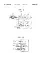
- FIG. 1is a block diagram of a communications system useful for incorporating an illustrative embodiment of the present invention.
- the system of FIG. 1illustrates systems known in the prior art, but modifications, and extensions described herein, will make clear the contributions of the present invention.
- FIG. 1represents a digital audio broadcasting system.
- an analog audio signal 101is fed into preprocessor 105 where it is sampled (typically at 48 Khz) and converted into a digital pulse code modulation (PCM) signal 106 (typically 16 bits) in standard fashion.
- PCMdigital pulse code modulation
- the PCM signal 106is fed into a perceptual audio coder (PAC) 110, which compresses the PCM signal and outputs the compressed PAC signal to a communications channel/storage medium 200.
- PACperceptual audio coder
- the compressed PAC signalcan be further quantized and coded using traditional coding practices as known in the art, e.g., by the use of Huffman coding, before application to communications channel/storage medium 200.
- the compressed PAC signalis fed into a perceptual audio decoder 310, which decompresses the compressed PAC signal and outputs a PCM signal 311.
- the latteris fed into a post-processor 305, which creates an analog representation that is, ideally, identical to analog audio signal 101.
- PAC 110operates by sampling PCM signal 106 in the frequency domain and representing this signal by a sequence of transform values, or parameters, say by N spectral coefficients, or samples. For example, 1024 samples are taken over a frequency bandwidth of 0 to 20 Khz.
- Nis a power of 2 (such as 64, 256, or 1024) and n is equally likely to be odd or even.
- the subset nis time-varying, i.e., in each frame interval the number of samples, n, is determined anew.
- PAC 110generates a fixed number of bits over an interval of time, i.e., PAC 110 is a constant-bit rate coder.
- PAC 110is run at 128 kilo-bits/second (kbit/sec.) and uses 10 milli-second (msec.) size frames, each frame comprising 1,280 bits.
- An illustrative, and simplified, frame formatis shown in FIG. 2.
- Frame 205is divided into two portions: a fixed header portion 206 and a variable portion 207.
- the latterincludes the above-mentioned n time-varying subset of samples, or coefficients, and the former includes information, e.g., the value of n, so that perceptual audio decoder 310 can identify the location and the number of coefficients within each variable portion of each frame.
- the design of PAC 110includes a rate-control loop processor (not shown) such as described in the above-referenced '498 patent.
- the rate-control loop processor (not shown) within PAC 110further adjusts the number of samples, n, to approximately fit within the fixed size of each frame for transmission. Consequently, the rate-control loop processor may increase the resolution in some frames (i.e., increase the number of coefficients transmitted and, therefore, increase the value of n) and decrease the resolution in others (i.e., decrease the number of coefficients transmitted and, therefore, decrease the value of n) to accommodate the fixed frame size. Bit-stuffing is used where appropriate to fill out each frame to its predefined size.
- Compressing techniquessuch as the above-described perceptual audio coding provide ways to efficiently transmit high-quality digital signals using a smaller bandwidth or storage size than the larger-sized original digital signal. As a result, it becomes easier to distribute, or copy, high-quality digital signals without regard to ownership or distribution rights. Therefore, and in accordance with the invention, I have discovered a way to integrate a "source label" into a data signal so that the "source label” is a relatively inseparable part of the data signal as it is distributed or copied or retransmitted. In the following illustrative embodiment, the inventive concept is shown in the context of the above-described perceptual audio coding system of FIG. 1.
- FIG. 3is a block diagram of a source apparatus, or transmitter, 400 embodying the principles of the invention.
- Source apparatus 400includes a number of functional building blocks, e.g., a source label coder. The functions of any one or more of these building blocks can be carried out using one or more appropriately programmed processors. Except for the inventive concept, source apparatus 400 functions as in the prior art, as described above.
- an analog audio signal 401is fed into preprocessor 405 where it is sampled (typically at 48 Khz) and converted into a digital pulse code modulation (PCM) signal 406 (typically 16 bits) in standard fashion.
- PCMdigital pulse code modulation
- the PCM signal 406is then fed into a perceptual audio coder (PAC) 410, which compresses the PCM signal and outputs the compressed PAC signal to a communications channel/storage medium 200.
- the compressed PAC signalis transmitted in a sequence of frames, each frame of 10 msec. duration and carrying a predefined number of bits, e.g., 1,280 bits of data. In each frame, a time-varying number, n, of samples or coefficients are transmitted representing the compressed PAC signal.
- the time-varying number of samples, nis used to additionally represent a "source label."
- na single bit of additional information is transmitted in each frame by illustratively defining the following association, or codebook:
- nif the value of n is odd, then a binary "1" is transmitted.
- the rate-control loop processor within PAC 410appropriately forces the time-varying number of samples, n, to be either even or odd, in response to a control signal from source label coder 420.
- FIG. 4is an illustrative flow diagram of a method for use in the apparatus of FIG. 3.
- source label coder 420receives the "source label” from identification source 415 in step 600.
- Identification source 415is representative of any method or apparatus for generating a sequence of binary ones and zeroes, the pattern of which is predefined to be associated with a particular source.
- identification source 415in this example, is simply a memory device that stores a predefined "source label,” which is accessed by source label coder 420 via signaling 416.
- the "source label”is L bits in length, where L is equal to 10, and is equal to "1100110011,” which could be predefined as being associated with, e.g., "AT&T.” Any number of known methods can be used to store the "source label” in identification source 415, and will not be described herein.
- source label coder 420sends a predefined "idle flag" to PAC 410 in step 610.
- the predefined idle flagis a predefined binary bit pattern for the purpose of synchronizing a receiver to recover the transmitted source label (described below). For illustrative purposes, this idle flag is the bit pattern "0000000000.”
- source label coder 420sends the "source label” to PAC 410 in step 620. For a 10 msec. frame, the idle flag and the source label can be throughput in the course of 200 msec.
- source label coder 420monitors an "in progress" signal 412 from PAC 410.
- source label coder 420repeats steps 610 and 620 thereby transmitting the idle flag and the source label ad infinitum during the transmission of the compressed digital signal. On the other hand, if encoding of the analog audio signal has ceased, source label coder 420 ends the source label transmission in step 640.
- FIG. 5shows a resulting frame sequence from PAC 410.
- FIG. 6shows a flow diagram for a method of controlling PAC 410 in accordance with the principles of the invention.
- source level coder 420determines the value of the bit in step 660. If the value of the bit is equal to "1,” then source level coder 420 instructs PAC 410, via a control signal 421, to set the value of n to an odd number of samples in step 665. On the other hand, if the value of the bit is equal to "0,” then source level coder 420 instructs PAC 410, via the control signal 421, to set the value of n to an even number in step 670. It is assumed that PAC 410 provides to source label coder 420 the equivalent of a clocking signal 413, which is representative of the start of each frame to, in effect, cause source label coder 420 to "shift-out" the coding for the next bit.
- source label coder 420could translate the alpha-numeric representation to a sequence of bits, e.g., using an ASCII representation, which are then encoded by appropriate control of PAC 410 as described above.
- this translation of an alpha-numeric representation to sequence of bitscan be functionally included within identification source 415.
- FIG. 7is an illustrative flow diagram of a method for use within PAC 410 in accordance with the principles of the invention.
- PAC 410samples the control signal 421 in step 710 to determine if the value of n' matches the coding for the current source label bit. If the coding for the current source label bit is supposed to be "odd" and the value of n' is odd, then PAC 410 simply completes processing of the frame as in the prior art in step 715.
- step 715if the coding for the current source label bit is supposed to be "even" and the value of n' is even, PAC 410, again, completes processing in step 715. However, if the value of n' does not match the coding for the current source label bit then PAC 410 performs another iteration in step 705. As noted earlier, the value of the number of samples in each frame is equally likely to be odd or even, so the above rule leaves the encoding algorithm unaffected half of the time. The repetition of step 705 should, within a small number of repetitions, eventually produce a value n' that matches the coding of the current source level bit.
- the method of FIG. 8can be used within PAC 410.
- the method of FIG. 8is similar to the method of FIG. 7 except that if the value of n' does not match the coding for the current source label bit in step 710, step 720 is executed, in which PAC 410 alters the value of n' by one, i.e., to n'-1. This reduces the resolution by one sample, i.e., one sample is dropped.
- n' ⁇ 1(which is typical) the effect on signal quality is minimal, especially because a perceptual coding algorithm has a built-in hierarchy that steers the process of going from n to n-1, i.e., one could eliminate the component less likely to impact noise audibility (or visibility). (Alternatively, n'+1 could be used, which would increase the resolution but may require re-convergence to a set of n'+1 samples).
- nthe number of samples, n, is not directly controlled, and the iterative method of FIG. 7 may have to be used. Also, in perceptual coders where n is even by definition, other source level bit definitions, or codebooks, can be specified. For example, a value of n that is a multiple of 4 could be associated with a source level bit value of one, leaving other values of n to be associated with a source level bit value of zero.
- receiver 500is described in accordance with the principles of the invention.
- the "source label”is recovered simply by checking the odd or even nature of rn, which is the number of retained coefficients in each received frame as described further below.
- receiver 500includes a number of functional building blocks, e.g., a source label decoder. The functions of any one or more of these building blocks can be carried out using one or more appropriately programmed processors. Except for the inventive concept, receiver 500 functions as in the prior art, as described above.
- the compressed PAC signalis received from communications channel/storage medium 200 and applied to a perceptual audio decoder 510, which decompresses the compressed PAC signal and outputs a PCM signal 511.
- the latteris fed into a post-processor 505, which creates an analog representation that is, ideally, identical to analog audio signal 501 of FIG. 3.
- perceptual audio decoder 510provides the number of samples, rn, received in each frame to monitor 530, via signaling 512.
- perceptual audio decoder 510provides a frame valid signal 513 to monitor 530 to, in effect, bit-synchronize monitor 530 to the received encoded source label signal.
- Monitor 530comprises display 525 and source label decoder 520, which receives frame valid signal 513 and the number of received samples, rn.
- FIG. 10shows an illustrative flow diagram of a method for recovering the "source label" in receiver 500.
- source label decoder 520receives rn in step 805.
- source label decoder 520decodes the value of rn in accordance with the above-defined "codebook.” That is, if the value of rn is even, source label decoder 520 shifts a "0" into a register (not shown). On the other hand, if the value of rn is odd, source label decoder 520 shifts a "1" into a register (not shown).
- source label decoder 520recovers the "source label.”
- the transmission format for the encoded source labelcomprises an idle flag, which is a sequence of 10 bits of zero value, followed by the 10-bit source label. Consequently, after decoding the bit value in step 810, source label decoder 520 performs a number of evaluations in step 815 depending on whether source label decoder 520 is in an "idle flag” state or a "source label” state.
- source label decoder 520starts in an "idle flag" state. In this state, source label decoder 520 checks if an idle flag, i.e., a sequence of bit values matching the pattern of an idle flag, is detected in step 815. If no idle flag is detected, then source label decoder 520 returns to 805 to receive the next value of rn.
- an idle flagi.e., a sequence of bit values matching the pattern of an idle flag
- source label decoder 520switches to the "source label” state and counts the reception of L, the number of bits comprising the "source label.”
- Lis equal to 10 bits. As long as the number of received bits is less than L, source label decoder 520 returns to step 805 to receive the next value of rn.
- source label decoder 520has recovered the "source label.” While the 10 bit sequence could be directly provided to display 525, it is presumed that source label decoder 520 includes a predefined "lookup" table to further translate the 10 bit "source label” to the predetermined alpha-numeric representation, which in this example is "AT&T.”
- Source label decoder 520updates display 525 with, in effect, the recovered source label (be it binary or alpha-numeric) in step 820. In addition, source label decoder 520 switches back to the "idle flag" state and returns to step 805 to repeat the process. From this description, it can be observed that simply monitoring the value of rn over a number of frames of the received signal easily identifies the source of the received signal.
- the use of the timevarying number of samples, n, to represent a "source label”is advantageous for a number of reasons.
- use of the time-varying number of samples, neffectively sends the "source label” using only 1 bit of information in each frame.
- the above bits comprising the encoded "source label”may be compromised.
- the firstis through transmission errors. If transmission errors are a problem, these can be addressed by standard means of distinct layers of error protection, e.g., attaching error-detection/correction bits to the encoded source label.
- source label decoder 520is appropriately modified to detect and/or correct the errors. For example, a parity bit can be added to the encoded source label to provide a rudimentary level of error detection.
- the encoded "source label”is constantly repeated, perhaps once every second, thus providing a powerful built-in redundancy for protection of the "source label.”
- inventive conceptis applicable to variable bit rate perceptual coders.
- inventive conceptis applicable to other encoding applications such as video coding or, for that matter, any encoding application where a parameter of the encoded signal is inextricably coupled to both a) decoding the signal, and b) identifying a source of the encoded signal.
Landscapes
- Engineering & Computer Science (AREA)
- Signal Processing (AREA)
- Compression, Expansion, Code Conversion, And Decoders (AREA)
Abstract
Description
Claims (43)
Priority Applications (1)
| Application Number | Priority Date | Filing Date | Title |
|---|---|---|---|
| US08/573,738US5826227A (en) | 1995-12-18 | 1995-12-18 | Hiding a source identifier within a signal |
Applications Claiming Priority (1)
| Application Number | Priority Date | Filing Date | Title |
|---|---|---|---|
| US08/573,738US5826227A (en) | 1995-12-18 | 1995-12-18 | Hiding a source identifier within a signal |
Publications (1)
| Publication Number | Publication Date |
|---|---|
| US5826227Atrue US5826227A (en) | 1998-10-20 |
Family
ID=24293197
Family Applications (1)
| Application Number | Title | Priority Date | Filing Date |
|---|---|---|---|
| US08/573,738Expired - LifetimeUS5826227A (en) | 1995-12-18 | 1995-12-18 | Hiding a source identifier within a signal |
Country Status (1)
| Country | Link |
|---|---|
| US (1) | US5826227A (en) |
Cited By (31)
| Publication number | Priority date | Publication date | Assignee | Title |
|---|---|---|---|---|
| WO1999063688A1 (en)* | 1998-06-04 | 1999-12-09 | Innes Corporation Pty. Ltd. | Traffic verification system |
| US20020026255A1 (en)* | 2000-08-25 | 2002-02-28 | Masahiro Sueyoshi | Digital interface device |
| US6381341B1 (en) | 1996-05-16 | 2002-04-30 | Digimarc Corporation | Watermark encoding method exploiting biases inherent in original signal |
| US6408082B1 (en) | 1996-04-25 | 2002-06-18 | Digimarc Corporation | Watermark detection using a fourier mellin transform |
| US20020088570A1 (en)* | 1998-05-08 | 2002-07-11 | Sundaram V.S. Meenakshi | Ozone bleaching of low consistency pulp using high partial pressure ozone |
| US6424725B1 (en) | 1996-05-16 | 2002-07-23 | Digimarc Corporation | Determining transformations of media signals with embedded code signals |
| US6549753B1 (en)* | 1996-09-19 | 2003-04-15 | Nokia Corporation | Signalling method in a digital radio system wherein signaling data is placed in the signal based on control information |
| US6553129B1 (en) | 1995-07-27 | 2003-04-22 | Digimarc Corporation | Computer system linked by using information in data objects |
| US20030086585A1 (en)* | 1993-11-18 | 2003-05-08 | Rhoads Geoffrey B. | Embedding auxiliary signal with multiple components into media signals |
| US20030103645A1 (en)* | 1995-05-08 | 2003-06-05 | Levy Kenneth L. | Integrating digital watermarks in multimedia content |
| US20030123659A1 (en)* | 2001-12-28 | 2003-07-03 | Forstrom Howard Scott | Digital multimedia watermarking for source identification |
| US6611607B1 (en) | 1993-11-18 | 2003-08-26 | Digimarc Corporation | Integrating digital watermarks in multimedia content |
| US6614914B1 (en) | 1995-05-08 | 2003-09-02 | Digimarc Corporation | Watermark embedder and reader |
| AU764862B2 (en)* | 1998-06-04 | 2003-09-04 | Innes Corporation Pty Ltd | Traffic verification system |
| US20040030556A1 (en)* | 1999-11-12 | 2004-02-12 | Bennett Ian M. | Speech based learning/training system using semantic decoding |
| US6721337B1 (en)* | 1999-08-24 | 2004-04-13 | Ibiquity Digital Corporation | Method and apparatus for transmission and reception of compressed audio frames with prioritized messages for digital audio broadcasting |
| US6768809B2 (en) | 2000-02-14 | 2004-07-27 | Digimarc Corporation | Digital watermark screening and detection strategies |
| US20040249635A1 (en)* | 1999-11-12 | 2004-12-09 | Bennett Ian M. | Method for processing speech signal features for streaming transport |
| US20060122834A1 (en)* | 2004-12-03 | 2006-06-08 | Bennett Ian M | Emotion detection device & method for use in distributed systems |
| US20070189533A1 (en)* | 1996-04-25 | 2007-08-16 | Rhoads Geoffrey B | Wireless Methods And Devices Employing Steganography |
| US20070230739A1 (en)* | 1997-02-20 | 2007-10-04 | Andrew Johnson | Digital watermark systems and methods |
| US20080120503A1 (en)* | 2001-10-30 | 2008-05-22 | Kime Gregory C | Automated content source validation for streaming data |
| US20080215333A1 (en)* | 1996-08-30 | 2008-09-04 | Ahmed Tewfik | Embedding Data in Audio and Detecting Embedded Data in Audio |
| US7486799B2 (en) | 1995-05-08 | 2009-02-03 | Digimarc Corporation | Methods for monitoring audio and images on the internet |
| US7522728B1 (en) | 1993-11-18 | 2009-04-21 | Digimarc Corporation | Wireless methods and devices employing steganography |
| US7647225B2 (en) | 1999-11-12 | 2010-01-12 | Phoenix Solutions, Inc. | Adjustable resource based speech recognition system |
| US7698131B2 (en) | 1999-11-12 | 2010-04-13 | Phoenix Solutions, Inc. | Speech recognition system for client devices having differing computing capabilities |
| US20100205445A1 (en)* | 2001-04-16 | 2010-08-12 | Anglin Hugh W | Watermark systems and methods |
| US8073193B2 (en) | 1994-10-21 | 2011-12-06 | Digimarc Corporation | Methods and systems for steganographic processing |
| CN111343038A (en)* | 2018-12-19 | 2020-06-26 | Aptiv技术有限公司 | Method and system for testing the quality of signal transmission in a communication system |
| US11959963B2 (en) | 2022-02-15 | 2024-04-16 | Aptiv Technologies AG | Integrity tests for mixed analog digital systems |
Citations (8)
| Publication number | Priority date | Publication date | Assignee | Title |
|---|---|---|---|---|
| US4516241A (en)* | 1983-07-11 | 1985-05-07 | At&T Bell Laboratories | Bit compression coding with embedded signaling |
| US5282197A (en)* | 1992-05-15 | 1994-01-25 | International Business Machines | Low frequency audio sub-channel embedded signalling |
| US5285498A (en)* | 1992-03-02 | 1994-02-08 | At&T Bell Laboratories | Method and apparatus for coding audio signals based on perceptual model |
| US5319735A (en)* | 1991-12-17 | 1994-06-07 | Bolt Beranek And Newman Inc. | Embedded signalling |
| US5341457A (en)* | 1988-12-30 | 1994-08-23 | At&T Bell Laboratories | Perceptual coding of audio signals |
| US5367608A (en)* | 1990-05-14 | 1994-11-22 | U.S. Philips Corporation | Transmitter, encoding system and method employing use of a bit allocation unit for subband coding a digital signal |
| US5463641A (en)* | 1993-07-16 | 1995-10-31 | At&T Ipm Corp. | Tailored error protection |
| US5491773A (en)* | 1991-09-02 | 1996-02-13 | U.S. Philips Corporation | Encoding system comprising a subband coder for subband coding of a wideband digital signal constituted by first and second signal components |
- 1995
- 1995-12-18USUS08/573,738patent/US5826227A/ennot_activeExpired - Lifetime
Patent Citations (8)
| Publication number | Priority date | Publication date | Assignee | Title |
|---|---|---|---|---|
| US4516241A (en)* | 1983-07-11 | 1985-05-07 | At&T Bell Laboratories | Bit compression coding with embedded signaling |
| US5341457A (en)* | 1988-12-30 | 1994-08-23 | At&T Bell Laboratories | Perceptual coding of audio signals |
| US5367608A (en)* | 1990-05-14 | 1994-11-22 | U.S. Philips Corporation | Transmitter, encoding system and method employing use of a bit allocation unit for subband coding a digital signal |
| US5491773A (en)* | 1991-09-02 | 1996-02-13 | U.S. Philips Corporation | Encoding system comprising a subband coder for subband coding of a wideband digital signal constituted by first and second signal components |
| US5319735A (en)* | 1991-12-17 | 1994-06-07 | Bolt Beranek And Newman Inc. | Embedded signalling |
| US5285498A (en)* | 1992-03-02 | 1994-02-08 | At&T Bell Laboratories | Method and apparatus for coding audio signals based on perceptual model |
| US5282197A (en)* | 1992-05-15 | 1994-01-25 | International Business Machines | Low frequency audio sub-channel embedded signalling |
| US5463641A (en)* | 1993-07-16 | 1995-10-31 | At&T Ipm Corp. | Tailored error protection |
Cited By (77)
| Publication number | Priority date | Publication date | Assignee | Title |
|---|---|---|---|---|
| US6567533B1 (en) | 1993-11-18 | 2003-05-20 | Digimarc Corporation | Method and apparatus for discerning image distortion by reference to encoded marker signals |
| US7171016B1 (en) | 1993-11-18 | 2007-01-30 | Digimarc Corporation | Method for monitoring internet dissemination of image, video and/or audio files |
| US7113614B2 (en) | 1993-11-18 | 2006-09-26 | Digimarc Corporation | Embedding auxiliary signals with multiple components into media signals |
| US6975746B2 (en) | 1993-11-18 | 2005-12-13 | Digimarc Corporation | Integrating digital watermarks in multimedia content |
| US7522728B1 (en) | 1993-11-18 | 2009-04-21 | Digimarc Corporation | Wireless methods and devices employing steganography |
| US6700990B1 (en) | 1993-11-18 | 2004-03-02 | Digimarc Corporation | Digital watermark decoding method |
| US6611607B1 (en) | 1993-11-18 | 2003-08-26 | Digimarc Corporation | Integrating digital watermarks in multimedia content |
| US20030086585A1 (en)* | 1993-11-18 | 2003-05-08 | Rhoads Geoffrey B. | Embedding auxiliary signal with multiple components into media signals |
| US8073193B2 (en) | 1994-10-21 | 2011-12-06 | Digimarc Corporation | Methods and systems for steganographic processing |
| US7486799B2 (en) | 1995-05-08 | 2009-02-03 | Digimarc Corporation | Methods for monitoring audio and images on the internet |
| US7460726B2 (en) | 1995-05-08 | 2008-12-02 | Digimarc Corporation | Integrating steganographic encoding in multimedia content |
| US6614914B1 (en) | 1995-05-08 | 2003-09-02 | Digimarc Corporation | Watermark embedder and reader |
| US7224819B2 (en) | 1995-05-08 | 2007-05-29 | Digimarc Corporation | Integrating digital watermarks in multimedia content |
| US20030103645A1 (en)* | 1995-05-08 | 2003-06-05 | Levy Kenneth L. | Integrating digital watermarks in multimedia content |
| US6718047B2 (en) | 1995-05-08 | 2004-04-06 | Digimarc Corporation | Watermark embedder and reader |
| US7602978B2 (en) | 1995-05-08 | 2009-10-13 | Digimarc Corporation | Deriving multiple identifiers from multimedia content |
| US6775392B1 (en) | 1995-07-27 | 2004-08-10 | Digimarc Corporation | Computer system linked by using information in data objects |
| US6553129B1 (en) | 1995-07-27 | 2003-04-22 | Digimarc Corporation | Computer system linked by using information in data objects |
| US6408082B1 (en) | 1996-04-25 | 2002-06-18 | Digimarc Corporation | Watermark detection using a fourier mellin transform |
| US8369363B2 (en) | 1996-04-25 | 2013-02-05 | Digimarc Corporation | Wireless methods and devices employing plural-bit data derived from audio information |
| US20070189533A1 (en)* | 1996-04-25 | 2007-08-16 | Rhoads Geoffrey B | Wireless Methods And Devices Employing Steganography |
| US7715446B2 (en) | 1996-04-25 | 2010-05-11 | Digimarc Corporation | Wireless methods and devices employing plural-bit data derived from audio information |
| US6424725B1 (en) | 1996-05-16 | 2002-07-23 | Digimarc Corporation | Determining transformations of media signals with embedded code signals |
| US6381341B1 (en) | 1996-05-16 | 2002-04-30 | Digimarc Corporation | Watermark encoding method exploiting biases inherent in original signal |
| US20080215333A1 (en)* | 1996-08-30 | 2008-09-04 | Ahmed Tewfik | Embedding Data in Audio and Detecting Embedded Data in Audio |
| US8306811B2 (en) | 1996-08-30 | 2012-11-06 | Digimarc Corporation | Embedding data in audio and detecting embedded data in audio |
| US6549753B1 (en)* | 1996-09-19 | 2003-04-15 | Nokia Corporation | Signalling method in a digital radio system wherein signaling data is placed in the signal based on control information |
| US8364966B2 (en) | 1997-02-20 | 2013-01-29 | Digimarc Corporation | Digital watermark systems and methods |
| US7987370B2 (en) | 1997-02-20 | 2011-07-26 | Digimarc Corporation | Digital watermark systems and methods |
| US20080065896A1 (en)* | 1997-02-20 | 2008-03-13 | Andrew Johnson | Digital Watermark Systems and Methods |
| US20070230739A1 (en)* | 1997-02-20 | 2007-10-04 | Andrew Johnson | Digital watermark systems and methods |
| US20080130944A1 (en)* | 1997-02-20 | 2008-06-05 | Andrew Johnson | Digital Watermark Systems and Methods |
| US8037311B2 (en) | 1997-02-20 | 2011-10-11 | Digimarc Corporation | Digital watermark systems and methods |
| US20020088570A1 (en)* | 1998-05-08 | 2002-07-11 | Sundaram V.S. Meenakshi | Ozone bleaching of low consistency pulp using high partial pressure ozone |
| GB2342265A (en)* | 1998-06-04 | 2000-04-05 | Innes Corp Pty Limited | Traffic verification system |
| AU764862B2 (en)* | 1998-06-04 | 2003-09-04 | Innes Corporation Pty Ltd | Traffic verification system |
| WO1999063688A1 (en)* | 1998-06-04 | 1999-12-09 | Innes Corporation Pty. Ltd. | Traffic verification system |
| GB2342265B (en)* | 1998-06-04 | 2002-12-31 | Innes Corp Pty Ltd | Traffic verification system |
| US6757300B1 (en) | 1998-06-04 | 2004-06-29 | Innes Corporation Pty Ltd | Traffic verification system |
| US6721337B1 (en)* | 1999-08-24 | 2004-04-13 | Ibiquity Digital Corporation | Method and apparatus for transmission and reception of compressed audio frames with prioritized messages for digital audio broadcasting |
| US7376556B2 (en)* | 1999-11-12 | 2008-05-20 | Phoenix Solutions, Inc. | Method for processing speech signal features for streaming transport |
| US20040030556A1 (en)* | 1999-11-12 | 2004-02-12 | Bennett Ian M. | Speech based learning/training system using semantic decoding |
| US9190063B2 (en) | 1999-11-12 | 2015-11-17 | Nuance Communications, Inc. | Multi-language speech recognition system |
| US9076448B2 (en) | 1999-11-12 | 2015-07-07 | Nuance Communications, Inc. | Distributed real time speech recognition system |
| US8762152B2 (en) | 1999-11-12 | 2014-06-24 | Nuance Communications, Inc. | Speech recognition system interactive agent |
| US8352277B2 (en) | 1999-11-12 | 2013-01-08 | Phoenix Solutions, Inc. | Method of interacting through speech with a web-connected server |
| US7555431B2 (en) | 1999-11-12 | 2009-06-30 | Phoenix Solutions, Inc. | Method for processing speech using dynamic grammars |
| US20050086059A1 (en)* | 1999-11-12 | 2005-04-21 | Bennett Ian M. | Partial speech processing device & method for use in distributed systems |
| US7624007B2 (en) | 1999-11-12 | 2009-11-24 | Phoenix Solutions, Inc. | System and method for natural language processing of sentence based queries |
| US7647225B2 (en) | 1999-11-12 | 2010-01-12 | Phoenix Solutions, Inc. | Adjustable resource based speech recognition system |
| US7657424B2 (en) | 1999-11-12 | 2010-02-02 | Phoenix Solutions, Inc. | System and method for processing sentence based queries |
| US7672841B2 (en) | 1999-11-12 | 2010-03-02 | Phoenix Solutions, Inc. | Method for processing speech data for a distributed recognition system |
| US7698131B2 (en) | 1999-11-12 | 2010-04-13 | Phoenix Solutions, Inc. | Speech recognition system for client devices having differing computing capabilities |
| US7702508B2 (en) | 1999-11-12 | 2010-04-20 | Phoenix Solutions, Inc. | System and method for natural language processing of query answers |
| US20050080614A1 (en)* | 1999-11-12 | 2005-04-14 | Bennett Ian M. | System & method for natural language processing of query answers |
| US7725321B2 (en) | 1999-11-12 | 2010-05-25 | Phoenix Solutions, Inc. | Speech based query system using semantic decoding |
| US7725307B2 (en) | 1999-11-12 | 2010-05-25 | Phoenix Solutions, Inc. | Query engine for processing voice based queries including semantic decoding |
| US7725320B2 (en) | 1999-11-12 | 2010-05-25 | Phoenix Solutions, Inc. | Internet based speech recognition system with dynamic grammars |
| US7729904B2 (en) | 1999-11-12 | 2010-06-01 | Phoenix Solutions, Inc. | Partial speech processing device and method for use in distributed systems |
| US7392185B2 (en) | 1999-11-12 | 2008-06-24 | Phoenix Solutions, Inc. | Speech based learning/training system using semantic decoding |
| US7831426B2 (en) | 1999-11-12 | 2010-11-09 | Phoenix Solutions, Inc. | Network based interactive speech recognition system |
| US7873519B2 (en) | 1999-11-12 | 2011-01-18 | Phoenix Solutions, Inc. | Natural language speech lattice containing semantic variants |
| US7912702B2 (en) | 1999-11-12 | 2011-03-22 | Phoenix Solutions, Inc. | Statistical language model trained with semantic variants |
| US8229734B2 (en) | 1999-11-12 | 2012-07-24 | Phoenix Solutions, Inc. | Semantic decoding of user queries |
| US20040249635A1 (en)* | 1999-11-12 | 2004-12-09 | Bennett Ian M. | Method for processing speech signal features for streaming transport |
| US6768809B2 (en) | 2000-02-14 | 2004-07-27 | Digimarc Corporation | Digital watermark screening and detection strategies |
| US6931371B2 (en)* | 2000-08-25 | 2005-08-16 | Matsushita Electric Industrial Co., Ltd. | Digital interface device |
| US20020026255A1 (en)* | 2000-08-25 | 2002-02-28 | Masahiro Sueyoshi | Digital interface device |
| US20100205445A1 (en)* | 2001-04-16 | 2010-08-12 | Anglin Hugh W | Watermark systems and methods |
| US7949774B2 (en)* | 2001-10-30 | 2011-05-24 | Intel Corporation | Automated content source validation for streaming data |
| US20080120503A1 (en)* | 2001-10-30 | 2008-05-22 | Kime Gregory C | Automated content source validation for streaming data |
| EP1326422A3 (en)* | 2001-12-28 | 2004-05-12 | Itt Manufacturing Enterprises, Inc. | Digital multimedia watermarking for source identification |
| US20030123659A1 (en)* | 2001-12-28 | 2003-07-03 | Forstrom Howard Scott | Digital multimedia watermarking for source identification |
| US7260722B2 (en)* | 2001-12-28 | 2007-08-21 | Itt Manufacturing Enterprises, Inc. | Digital multimedia watermarking for source identification |
| US20060122834A1 (en)* | 2004-12-03 | 2006-06-08 | Bennett Ian M | Emotion detection device & method for use in distributed systems |
| CN111343038A (en)* | 2018-12-19 | 2020-06-26 | Aptiv技术有限公司 | Method and system for testing the quality of signal transmission in a communication system |
| US11959963B2 (en) | 2022-02-15 | 2024-04-16 | Aptiv Technologies AG | Integrity tests for mixed analog digital systems |
Similar Documents
| Publication | Publication Date | Title |
|---|---|---|
| US5826227A (en) | Hiding a source identifier within a signal | |
| AU747694B2 (en) | Device and method for entropy encoding of information words and device and method for decoding entropy-encoded information words | |
| EP1269669B1 (en) | Apparatus and method for adding an inaudible code to an audio signal | |
| TW343410B (en) | Method and apparatus for detecting communication signals having unequal error protection | |
| KR890005236B1 (en) | Interface method and apparatus | |
| WO2000002392A3 (en) | Scalable video coding system | |
| AU5689896A (en) | Video data encoder and decoder | |
| EP0710022A3 (en) | System and method for encoding digital information in a television signal | |
| CA2409499A1 (en) | Video coding using the sequence numbers of reference pictures for error correction | |
| WO2003077425A1 (en) | Digital signal encoding method, decoding method, encoding device, decoding device, digital signal encoding program, and decoding program | |
| NO981532L (en) | Method and apparatus for encoding audio signals | |
| AU7082994A (en) | Apparatus and method for coding/decoding subtitles data | |
| JPH02504337A (en) | Device for protecting energy information in subband coding | |
| EP0953965A4 (en) | Music transmitting device, music receiving device, music transmitting method, music receiving method, and music transmitting system | |
| WO1999048212A3 (en) | Arithmetic encoding/decoding of a multi-channel information signal | |
| MXPA03003512A (en) | Image encoding method, image decoding method, and apparatus thereof. | |
| CA2135415A1 (en) | Device and method for efficient utilization of allocated transmission medium bandwidth | |
| CA2195037A1 (en) | System and method for encoding digital information in a television signal | |
| MY112024A (en) | Method and apparatus for encoding and decoding information in a digital communication system | |
| EP1417842B1 (en) | Protection of streaming a/v data | |
| US5375171A (en) | Transmission system, and transmitter and receiver used in the transmission system for transmitting and receiving digital signals containing modulated bit allocation information | |
| AU6283900A (en) | Method for decreasing the processing capacity required by speech encoding and a network element | |
| KR860003717A (en) | Cryptographic digital signal transmission method and apparatus | |
| WO1993010623A1 (en) | Transmission system for coded speech signals and/or voiceband data | |
| KR100652004B1 (en) | Device and method for error correction of audio data |
Legal Events
| Date | Code | Title | Description |
|---|---|---|---|
| AS | Assignment | Owner name:LUCENT TECHNOLOGIES INC., NEW JERSEY Free format text:ASSIGNMENT OF ASSIGNORS INTEREST;ASSIGNOR:JAYANT, NUGGEHALLY SAMPATH;REEL/FRAME:007954/0008 Effective date:19960320 | |
| STCF | Information on status: patent grant | Free format text:PATENTED CASE | |
| AS | Assignment | Owner name:THE CHASE MANHATTAN BANK, AS COLLATERAL AGENT, TEX Free format text:CONDITIONAL ASSIGNMENT OF AND SECURITY INTEREST IN PATENT RIGHTS;ASSIGNOR:LUCENT TECHNOLOGIES INC. (DE CORPORATION);REEL/FRAME:011722/0048 Effective date:20010222 | |
| FEPP | Fee payment procedure | Free format text:PAYOR NUMBER ASSIGNED (ORIGINAL EVENT CODE: ASPN); ENTITY STATUS OF PATENT OWNER: LARGE ENTITY | |
| FPAY | Fee payment | Year of fee payment:4 | |
| FPAY | Fee payment | Year of fee payment:8 | |
| AS | Assignment | Owner name:LUCENT TECHNOLOGIES INC., NEW JERSEY Free format text:TERMINATION AND RELEASE OF SECURITY INTEREST IN PATENT RIGHTS;ASSIGNOR:JPMORGAN CHASE BANK, N.A. (FORMERLY KNOWN AS THE CHASE MANHATTAN BANK), AS ADMINISTRATIVE AGENT;REEL/FRAME:018590/0047 Effective date:20061130 | |
| FEPP | Fee payment procedure | Free format text:PAYER NUMBER DE-ASSIGNED (ORIGINAL EVENT CODE: RMPN); ENTITY STATUS OF PATENT OWNER: LARGE ENTITY Free format text:PAYOR NUMBER ASSIGNED (ORIGINAL EVENT CODE: ASPN); ENTITY STATUS OF PATENT OWNER: LARGE ENTITY | |
| FPAY | Fee payment | Year of fee payment:12 |