US5825908A - Anatomical visualization and measurement system - Google Patents
Anatomical visualization and measurement systemDownload PDFInfo
- Publication number
- US5825908A US5825908AUS08/581,055US58105595AUS5825908AUS 5825908 AUS5825908 AUS 5825908AUS 58105595 AUS58105595 AUS 58105595AUS 5825908 AUS5825908 AUS 5825908A
- Authority
- US
- United States
- Prior art keywords
- slice
- image
- data
- database
- anatomical
- Prior art date
- Legal status (The legal status is an assumption and is not a legal conclusion. Google has not performed a legal analysis and makes no representation as to the accuracy of the status listed.)
- Expired - Lifetime
Links
Images


Classifications
- G—PHYSICS
- G06—COMPUTING OR CALCULATING; COUNTING
- G06T—IMAGE DATA PROCESSING OR GENERATION, IN GENERAL
- G06T7/00—Image analysis
- G06T7/60—Analysis of geometric attributes
- G06T7/66—Analysis of geometric attributes of image moments or centre of gravity
- G—PHYSICS
- G06—COMPUTING OR CALCULATING; COUNTING
- G06T—IMAGE DATA PROCESSING OR GENERATION, IN GENERAL
- G06T7/00—Image analysis
- G06T7/60—Analysis of geometric attributes
- G06T7/62—Analysis of geometric attributes of area, perimeter, diameter or volume
- G—PHYSICS
- G06—COMPUTING OR CALCULATING; COUNTING
- G06T—IMAGE DATA PROCESSING OR GENERATION, IN GENERAL
- G06T2207/00—Indexing scheme for image analysis or image enhancement
- G06T2207/30—Subject of image; Context of image processing
- G06T2207/30004—Biomedical image processing
Definitions
- This inventionrelates to medical apparatus in general, and more particularly to anatomical visualization and measurement systems.
- scanning devicestypically include CT scanners, MRI devices, X-ray machines, ultrasound devices and the like, and essentially serve to provide the physician with some sort of visualization of the patient's interior anatomical structure prior to commencing the actual medical procedure.
- the physiciancan then use this information to plan the medical procedure in advance, taking into account patient-specific anatomical structure.
- the physiciancan also use the information obtained from such preliminary scanning to more precisely identify the location of selected structures (e.g., tumors and the like) which may themselves be located within the interior of internal organs or other internal body structures. As a result, the physician can then more easily “zero in” on such selected structures during the subsequent medical procedure.
- selected structurese.g., tumors and the like
- the anatomical structures of interest to the physicianmay be quite small and/or difficult to identify with the naked eye.
- preliminary scanning of the patient's interior anatomical structure using high resolution scanning devicescan help the physician locate various structures of interest during the subsequent medical procedure.
- scanning devices of the sort described aboveare frequently also used in purely diagnostic procedures.
- scanning devices of the sort described abovemight be used to look for stenosis in a blood vessel, or the buildup of plaque in a blood vessel, or a thinning of the aorta wall, etc.
- scanning devices of the sort described abovetend to generate two-dimensional (i.e., "2-D") images of the patient's anatomical structure.
- the scanning devicesare adapted to provide a set of 2-D images, with each 2-D image in the set being related to every other 2-D image in the set according to some pre-determined relationship.
- CT scannerstypically generate a series of 2-D images, with each 2-D image corresponding to a specific plane or "slice" taken through the patient's anatomical structure.
- each image plane or slicemay be set parallel to every other image plane or slice, and adjacent image planes or slices may be spaced a pre-determined distance apart.
- the parallel image planesmight be set 1 mm apart.
- the physiciancan view each 2-D image individually and, by viewing a series of 2-D images in proper sequence, can mentally generate a three-dimensional (i.e., "3-D") impression of the patient's interior anatomical structure.
- Some scanning devicesinclude, as part of their basic system, associated computer hardware and software for building a 3-D database of the patient's scanned anatomical structure using a plurality of the aforementioned 2-D images.
- some CT and MRI scannersinclude such associated computer hardware and software as part of their basic system.
- such associated computer hardware and softwaremay be provided independently of the scanning devices, as a sort of "add-on" to the system; in this case, the data from the scanned 2-D images is fed from the scanning device to the associated computer hardware and software in a separate step.
- a trained operator using such apparatuscan create a set of scanned 2-D images, assemble the data from these scanned 2-D images into a 3-D database of the scanned anatomical structure, and then generate various additional images of the scanned anatomical structure using the 3-D database.
- This featurehas been found to be a very powerful tool, since it essentially permits a physician to view the patient's scanned anatomical structure from a wide variety of different viewing positions. As a result, the physician's understanding of the patient's scanned anatomical structure is generally greatly enhanced.
- scanning systems of the sort described aboveoften include hardware and/or software tools to allow measurements to be made of the patient's scanned anatomical structure.
- many of these systemslet a physician overlay lines on an image of the patient's anatomical structure, and then calculate the length of these lines so as to indicate the size of the structure being viewed.
- each scanned 2-D slice imageis displayed as a separate and distinct image
- each image generated from the 3-D databaseis displayed as a separate and distinct image.
- physicianscan sometimes have difficulty correlating what they see on one image with what they see on another image.
- physicianscan sometimes have difficulty correlating what they see on a particular scanned 2-D slice image with what they see on a particular image generated from the 3-D database.
- a physicianmay be viewing images of a patient's scanned anatomical structure in preparation for conducting a subsequent medical procedure in which a prosthetic device must be fitted in the patient.
- a patientmay develop an abdominal aortic aneurysm ("AAA") in the vicinity of the aorta's iliac branching, and repair or replacement of the affected vascular structure with a prosthetic device may be indicated.
- AAAabdominal aortic aneurysm
- a physicianmay be desirable to provide a physician with a particular oblique view of a specified portion of a patient's anatomical structure. For example, it may be desirable to provide a physician with a view taken perpendicular to the length of a blood vessel, with that view being taken at a very specific location along that blood vessel. Such a view might be desired for comprehensional and/or measurement purposes. Unfortunately, it can be difficult and/or impossible to accurately generate such a view using existing visualization systems.
- a physicianmay be interested in accurately calculating a volume associated with a specific part of a patient's anatomy.
- a physicianmight wish to track the volume of a thrombus in an aorta over time, or the size of a tumor during chemotherapy, etc.
- itcan be difficult and/or impossible to accurately make such a calculation using existing visualization systems.
- one object of the present inventionis to provide an improved anatomical visualization and measurement system for visualizing and measuring anatomical structures.
- Another object of the present inventionis to provide an improved anatomical visualization and measurement system wherein a scanned 2-D slice image can be appropriately combined with an image generated from a 3-D database so as to create a single composite image.
- Another object of the present inventionis to provide an improved anatomical visualization and measurement system wherein a marker can be placed onto a 2-D slice image displayed on a screen, and this marker will be automatically incorporated, as appropriate, into a 3-D computer model maintained by the system, as well as into any other 2-D slice image data maintained by the system.
- Still another object of the present inventionis to provide an improved anatomical visualization and measurement system wherein a margin of pre-determined size can be associated with a marker of the sort described above, and further wherein the margin will be automatically incorporated into the 3-D computer model, and into any other 2-D slice image data, in association with that marker.
- Yet another object of the present inventionis to provide an improved anatomical visualization and measurement system wherein the periphery of objects contained in a 3-D computer model maintained by the system can be automatically identified in any 2-D slice image data maintained by the system, and further wherein the periphery of such objects can be highlighted as appropriate in 2-D slice images displayed by the system.
- Another object of the present inventionis to provide an improved anatomical visualization and measurement system wherein patient-specific anatomical dimensions such as length and/or cross-sectional dimensions can be quickly, easily and accurately determined.
- Still another object of the present inventionis to provide an improved anatomical visualization and measurement system which is particularly well adapted to determine patient-specific anatomical dimensions for structures which have a tortuous and/or branching configuration, e.g., blood vessels.
- Another object of the present inventionis to provide an improved anatomical visualization and measurement system wherein an appropriate set of scanned 2-D images can be assembled into a 3-D database, information regarding patient-specific anatomical structures can be segmented from the information contained in this 3-D database, and this segmented information can then be used to determine anatomical features such as a centerline for the anatomical structure which has been segmented.
- Still another object of the present inventionis to provide an improved anatomical visualization and measurement system which is able to easily and accurately present a physician with a particular oblique view of a specified portion of a patient's anatomical structure, e.g., a view taken perpendicular to the length of a blood vessel, with that view being taken at a very specific location along that blood vessel.
- Another object of the present inventionis to provide an improved anatomical visualization and measurement system wherein patient-specific anatomical volumes can be quickly, easily and accurately determined.
- Another object of the present inventionis to provide an improved anatomical visualization and measurement system wherein an appropriate set of scanned 2-D images can be assembled into a 3-D database, information regarding patient-specific anatomical structures can be segmented from the information contained in this 3-D database, and this segmented information can then be used to calculate desired patient-specific anatomical volumes.
- Another object of the present inventionis to provide an improved method for visualizing and measuring anatomical structures.
- Another object of the present inventionis to provide an improved method wherein patient-specific anatomical dimensions such as length and/or cross-sectional dimensions can be quickly, easily and accurately determined.
- Still another object of the present inventionis to provide an improved method wherein an appropriate set of scanned 2-D images can be assembled into a 3-D database, information regarding patient-specific anatomical structures can be segmented from the information contained in this 3-D database, and this segmented information can then be used to determine anatomical features such as a centerline for the anatomical structure which has been segmented.
- Yet another object of the present inventionis to provide a method for easily and accurately presenting a physician with a particular oblique view of a specified portion of a patient's anatomical structure, e.g., a view taken perpendicular to the length of a blood vessel, with that view being taken at a very specific location along that blood vessel.
- Yet another object of the present inventionis to provide an improved method for quickly, easily and accurately determining patient-specific anatomical volumes.
- an anatomical visualization and measurement systemcomprising a first database which comprises a plurality of 2-D slice images generated by scanning an anatomical structure. These 2-D slice images are stored in a first data format.
- a second databaseis also provided which comprises a 3-D computer model of the scanned anatomical structure.
- This 3-D computer modelcomprises a first software object which is representative of the scanned anatomical structure and which is defined by a 3-D geometry database.
- meansare provided for selecting a particular 2-D slice image from the first database.
- Meansare also provided for inserting a second software object into the 3-D computer model so as to augment the 3-D computer model.
- the second software objectis also defined by a 3-D geometry database, and includes a planar surface.
- the second software objectis inserted into the 3-D computer model at the position which corresponds to the position of the selected 2-D slice image relative to the scanned anatomical structure.
- Means for texture mapping the specific 2-D slice image onto the planar surface of the second software objectare also provided.
- Meansare also provided for displaying an image of the augmented 3-D computer model so as to simultaneously provide a view of both the first software object and the specific 2-D slice image which has been texture mapped onto the planar surface of the second software object.
- the systemcomprises a first database which comprises a plurality of 2-D slice images generated by scanning an anatomical structure. These 2-D slice images are stored in a first data format.
- a second databaseis also provided which comprises a 3-D computer model of the scanned anatomical structure.
- This 3-D computer modelcomprises a first software object which is representative of the scanned anatomical structure and which is defined by a 3-D geometry database.
- meansare also provided for inserting a second software object into the 3-D computer model so as to augment the 3-D computer model.
- the second software objectis also defined by a 3-D geometry database, and includes a planar surface.
- meansare also provided for determining the specific 2-D slice image which corresponds to the position of the planar surface of the second software object which has been inserted into the augmented 3-D computer model.
- meansare also provided for texture mapping the specific 2-D slice image corresponding to the position of that planar surface onto the planar surface of the second software object.
- display meansare also provided for displaying an image of the augmented 3-D computer model to a physician so as to simultaneously provide a view of the first software object and the specific 2-D slice image which has been texture mapped onto the planar surface of the second software object.
- the 3-D geometry databasemay comprise a surface model.
- systemmay further comprise means for inserting a marker into the first database, whereby the marker will be automatically incorporated into the second database, and further wherein the marker will be automatically displayed where appropriate in any image displayed by the system.
- systemmay further comprise a margin of pre-determined size associated with the aforementioned marker.
- systemmay further comprise means for automatically identifying the periphery of any objects contained in the second database and for identifying the corresponding data points in the first database, whereby the periphery of such objects can be highlighted as appropriate in any image displayed by the system.
- the scanned structurewill comprise an interior anatomical structure.
- the visualization and measurement systemmay incorporate means for determining patient-specific anatomical dimensions, such as length and/or cross-sectional dimensions, using appropriate scanned 2-D image data. More particularly, the visualization and measurement system may include means for assembling an appropriate set of scanned 2-D images into a 3-D database, means for segmenting information regarding patient-specific anatomical structures from the information contained in the 3-D database, means for determining from this segmented information anatomical features such as a centerline for the anatomical structure which has been segmented, means for specifying a measurement to be made based on the determined anatomical feature, and means for calculating the measurements so specified.
- the visualization and measurement systemmay include means for assembling an appropriate set of scanned 2-D images into a 3-D database, means for segmenting information regarding patient-specific anatomical structures from the information contained in the 3-D database, means for determining from this segmented information anatomical features such as a centerline for the anatomical structure which has been segmented, means for specifying a measurement to be made based on
- the visualization and measurement systemis particularly well adapted to determine patient-specific anatomical dimensions for structures which have a tortuous and/or branching configuration, e.g., blood vessels.
- the visualization and measurement systemis adapted to facilitate (1) assembling an appropriate set of scanned 2-D images into a 3-D database; (2) segmenting the volumetric data contained in the 3-D database into a set of 3-D locations corresponding to the specific anatomical structure to be measured; (3) specifying, for each branching structure contained within the specific anatomical structure of interest, a branch line in the volumetric data set that uniquely indicates that branch structure, with the branch line being specified by selecting appropriate start and end locations on two of the set of scanned 2-D images; (4) calculating, for each branching structure contained within the specific anatomical structure of interest, a centroid path in the volumetric data set for that branching structure, with the centroid path being determined by calculating, for each scanned 2-D image corresponding to the branch line, the centroid for the branch
- the visualization and measurement systemmay incorporate means for easily and accurately presenting a physician with a particular oblique view of a specified portion of a patient's anatomical structure, e.g., a view taken perpendicular to a blood vessel, at a very specific location along that blood vessel.
- the visualization and measurement systemmay incorporate means for more accurately measuring the dimensions of an anatomical structure by utilizing one or more oblique views taken along the length of that anatomical structure.
- the visualization and measurement systemmay incorporate means for determining patient-specific anatomical volumes using appropriate scanned 2-D image data. More particularly, the visualization and measurement system may include means for assembling an appropriate set of scanned 2-D images into a 3-D database, means for segmenting information regarding patient-specific anatomical structures from the information contained in the 3-D database, means for determining from this segmented information anatomical volumes from the anatomical structure which has been segmented, means for specifying a structure of interest, and means for calculating the volume of the specified structure.
- the present inventionalso comprises an improved method for visualizing and measuring anatomical structures.
- the present inventionalso comprises a method for calculating patient-specific anatomical dimensions using appropriate scanned 2-D image data.
- the methodcomprises the steps of (1) assembling an appropriate set of scanned 2-D images into a 3-D database; (2) segmenting information regarding patient-specific anatomical structures from the information contained in the 3-D database, (3) determining for this segmented information anatomical features such as a centerline for the anatomical structure which has been segmented; (4) specifying a measurement to be made based on the determined anatomical feature; and (5) calculating the measurement so specified.
- the present inventionalso comprises a method for easily and accurately presenting a physician with a particular oblique view of a specified portion of a patient's anatomical structure, e.g., a view taken perpendicular to a blood vessel, at a very specific location along that blood vessel.
- the present inventionalso comprises a method for calculating patient-specific anatomical volumes using appropriate scanned 2-D image data.
- the methodcomprises the steps of (1) assembling an appropriate set of scanned 2-D images into a 3-D database; (2) segmenting information regarding patient-specific anatomical structures from the information contained in the 3-D database, (3) determining from this segmented information volumes for the anatomical structure which has been segmented, (4) specifying a structure of interest, and (5) calculating the volume of the specified structure.
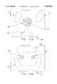
- FIG. 2is a 2-D slice image corresponding to an axial slice taken through the abdomen of an individual
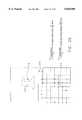
- FIG. 3shows a series of data frames corresponding to 2-D slice images arranged in a parallel array
- FIG. 4is a schematic view showing the scanning data contained within an exemplary data frame
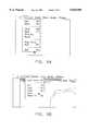
- FIG. 5shows scanning data stored in a first storage device or medium being retrieved, processed and then stored again in a second data storage device or medium;
- FIG. 6is a schematic view of a system for retrieving and viewing scanning data
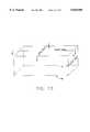
- FIG. 7is a schematic view of a unit cube for use in defining polygonal surface models
- FIG. 8illustrates the data file format of the polygonal surface model for the simple unit cube shown in FIG. 7;
- FIGS. 9A-9Fillustrate a variety of menu choices which may be utilized in connection with the present invention.
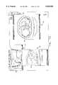
- FIG. 10illustrates an image drawn to a window using the data contained in the 3-D computer model associated with the present invention
- FIG. 11illustrates a 2-D slice image drawn to a window in accordance with the present invention
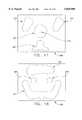
- FIG. 12illustrates a composite image formed from information contained in both the 3-D computer model and the 2-D slice image data structure
- FIG. 13is a schematic illustration showing the relationship between axial slices, sagittal slices and coronal slices
- FIG. 14illustrates three different images being displayed on a computer screen at the same time, with a marker being incorporated into each of the images;
- FIG. 15illustrates a marker shown in an image generated from the 3-D computer model, with the marker being surrounded by a margin of pre-determined size
- FIG. 16illustrates a 2-D slice image, wherein the periphery of an object has been automatically highlighted by the system
- FIG. 17is a schematic illustration showing various anatomical structures on a 2-D slice image, where that 2-D slice image has been taken axially through the abdomen of a patient, at a location above the aortic/iliac branching;
- FIG. 18is a schematic illustration showing various anatomical structures on another 2-D slice image, where that 2-D slice image has been taken through the abdomen of the same patient, at a location below the aortic/iliac branching;
- FIGS. 17A and 18Aare schematic illustrations like those of FIGS. 17 and 18, respectively, except that segmentation has been performed in the 3-D database so as to highlight the patient's vascular structure;
- FIG. 19is a schematic illustration showing that same patient's vascular structure in the region about the aortic/iliac branching, with branch lines having been specified for the patient's aorta and two iliac branches;
- FIG. 20is a schematic illustration showing how the centroid is calculated for the branch structure contained in a particular scanned 2-D image
- FIG. 21is a schematic illustration showing the tortuous centroid path calculated for each of the respective branch lines shown in FIG. 19;
- FIG. 22is a schematic illustration showing the space curve determined by applying a curve-fitting algorithm to two of the centroid paths shown in FIG. 21, whereby the structure between the branch lines is filled out and the centroid data "smoothed" through a "best fit” interpolation technique;
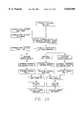
- FIG. 23is a flow chart illustrating how patient-specific anatomical dimensions can be determined from scanned 2-D image data in accordance with the present invention.
- FIG. 24is a schematic view showing an oblique slice polygon disposed perpendicular to the centerline of a blood vessel
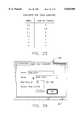
- FIG. 25is a cumulative sum table for calculating lengths along an anatomical structure
- FIG. 26illustrates a centerline length calculation dialogue box drawn to a window in a display
- FIG. 27illustrates a 3-D graphical icon which has been inserted into the 3-D model and which is visible on the display so as to show the portion of the centerline which has been specified by the physician for a length calculation;
- FIG. 28is a cumulative sum table for calculating volumes with respect to an anatomical structure
- FIG. 29illustrates a volume calculation dialogue box drawn to a window in a display
- FIG. 30illustrates a 3-D graphical icon which has been inserted into the 3-D model and which is visible on the display so as to show the volume which has been specified by the physician using the volume calculation dialogue box.
- a scanning device 5is shown as it scans the interior anatomical structure of a patient 10, as that patient 10 lies on a scanning platform 15.
- Scanning device 5is of the sort adapted to generate scanning data corresponding to a series of 2-D images, where each 2-D image corresponds to a specific viewing plane or "slice" taken through the patient's body. Furthermore, scanning device 5 is adapted so that the angle and spacing between adjacent image planes or slices can be very well defined, e.g., each image plane or slice may be set parallel to every other image plane or slice, and adjacent image planes or slices may be spaced a pre-determined distance apart. By way of example, the parallel image planes might be set 1 mm apart.
- the scanning data obtained by scanning device 5can be displayed as a 2-D slice image on a display 20, and/or it can be stored in its 2-D slice image data form in a first section 23 of a data storage device or medium 25. Furthermore, additional information associated with the scanning data (e.g., patient name, age, etc.) can be stored in a second section 27 of data storage device or medium 25.
- scanning device 5might comprise a CT scanner of the sort manufactured by GE Medical Systems of Milwaukee, Wis.
- a 2-D slice image of the sort generated by scanning device 5 and displayed on display 20might comprise the 2-D slice image shown in FIG. 2.
- the 2-D slice image showncorresponds to an axial slice taken through an individual's abdomen and showing, among other things, that individual's liver.
- Scanning device 5may format its scanning data in any one of a number of different data structures.
- scanning device 5might format its scanning data in the particular data format used by a CT scanner of the sort manufactured by GE Medical Systems of Milwaukee, Wis. More specifically, with such a scanning device, the scanning data is generally held as a series of data "frames", where each data frame corresponds to a particular 2-D slice image taken through the patient's body. Furthermore, within each data frame, the scanning data is generally organized so as to represent the scanned anatomical structure at a particular location within that 2-D slice image.
- Such a data structureis fairly common for scanning devices of the sort associated with the present invention. However, it should be appreciated that the present invention is not dependent on the particular data format utilized by scanning device 5.
- the scanning data provided by scanning device 5can be formatted in almost any desired data structure, so long as that data structure is well defined, whereby the scanning data can be retrieved and utilized as will hereinafter be disclosed in further detail.
- FIG. 3a series of data frames 30A, 30B, 30C, etc. are shown arranged in a parallel array.
- Each of these data frames 30A, 30B, 30C, etc.corresponds to a particular 2-D slice image taken through the patient's body by scanning device 5, where the 2-D slice images are taken parallel to one another.
- adjacent image planes or slicesare spaced apart by a constant, pre-determined distance, e.g., 1 mm.
- data frames 30A, 30B, 30C, etc.collectively form a volumetric data set which is representative of the patient's scanned anatomical structure.
- the scanning data contained within an exemplary data frame 30Ais shown represented in an X-Y coordinate scheme so as to quickly and easily identify the scanned anatomical structure disposed at a particular location within that 2-D slice image.
- the scanning data relating to a particular X-Y coordinaterepresents an image intensity value. This image intensity value generally reflects some attribute of the specific anatomical structure being scanned, e.g., the tissue density.
- the scanning data generated by scanning device 5is stored in its 2-D slice image data form in first section 23 of data storage device or medium 25, with the scanning data being stored in a particular data format as determined by the manufacturer of scanning device 5.
- the scanning data stored in first section 23 of data storage device or medium 25is retrieved, processed and then stored again in a data storage device or medium 30.
- the scanning data stored in first section 23 of data storage device or medium 25is retrieved and processed so as to convert the scanning data generated by scanning device 5 from its 2-D slice image data form into a 3-D computer model of the patient's anatomical structure.
- This 3-D computer modelis then stored in a first section 35 of data storage device or medium 30.
- the scanning data stored in first section 23 of data storage device or medium 25is retrieved and processed as necessary so as to convert the scanning data into a preferred data format for the 2-D slice image data.
- the 2-D slice image datais then stored in this preferred data format in second section 40 of data storage device or medium 30.
- the additional information associated with the scanning data(e.g., patient name, age, etc.) which was previously stored in second section 27 of data storage device or medium 25 can be stored in a third section 42 of data storage device or medium 30.
- the 3-D computer modelhas been stored in first section 35 of data storage device or medium 30, and the 2-D slice image data has been stored in a preferred data format in second section 40 of data storage device or medium 30, a physician can then use an appropriately programmed computer to access the 3-D computer model stored in first section 35 of data storage device or medium 30, and/or the 2-D slice image data stored in second section 40 of data storage device or medium 30, to generate desired patient-specific images.
- a physiciancan use an appropriately programmed computer 50, operated by input devices 55, to access the 3-D computer model stored in first section 35 of data storage device or medium 30, and/or the 2-D slice image data stored in second section 40 of data storage device or medium 30, so as to generate the desired patient-specific images and display those images on a display 60.
- the 3-D computer model contained in first section 35 of data storage device or medium 30is preferably structured as a collection of software objects, with each software object being defined by a polygonal surface model of the sort well known in the art.
- a scanned anatomical structuresuch as a human liver might be modeled as three distinct software objects, with the outer surface of the general mass of the liver being one software object, the outer surface of the vascular structure of the liver being a second software object, and the outer surface of a tumor located in the liver being a third software object.
- FIGS. 7 and 8illustrate a typical manner of defining a software object by a polygonal surface model.
- FIG. 7illustrates the vertices of a unit cube set in an X-Y-Z coordinate system
- FIG. 8illustrates the data file format of the polygonal surface model for this simple unit cube.
- more complex shapessuch as human anatomical structure can be expressed in corresponding terms.
- first section 35 of data storage device or medium 30is created by analyzing the 2-D slice image data stored in first section 23 of data storage device or medium 25 using techniques well known in the art.
- the 2-D slice image data stored in first section 23 of data storage device or medium 25might be processed using the well known "Marching Cubes” algorithm, which is a so-called “brute force” surface construction algorithm that extracts isodensity surfaces from a volumetric data set, producing from one to five triangles within voxels that contain the surface.
- the 2-D slice image data stored in first section 23 of data storage device or medium 25might be processed into the 3-D computer model stored in first section 35 of data storage device or medium 30 by some other appropriate modeling algorithm so as to yield the desired 3-D computer model which is stored in first section 35 of data storage device or medium 30.
- the specific data structure used to store the 2-D slice image data in second section 40 of data storage device or medium 30will also depend on the specific nature of computer 50 and on the particular operating system and application software being run on computer 50.
- the 2-D slice image data contained in second section 40 of data storage device or medium 30is preferably structured as a series of data "frames", where each data frame corresponds to a particular 2-D slice image taken through the patient's body, and where the scanning data within each data frame is organized so as to represent the scanned anatomical structure at a particular location within that 2-D slice image.
- computer 50comprise a Power PC-based, Macintosh operating system ("Mac OS") type of computer, e.g. a Power PC Macintosh 8100/80 of the sort manufactured by Apple Computer, Inc. of Cupertino, Calif.
- Mac OSPower PC-based, Macintosh operating system
- computer 50be running Macintosh operating system software, e.g. Mac OS Ver. 7.5.1, such that computer 50 can readily access a 3-D computer model formatted in Apple's well-known QuickDraw 3-D data format and display images generated from that 3-D computer model, and such that computer 50 can readily access and display 2-D images formatted in Apple's well-known QuickTime image data format.
- Input devices 55preferably comprise the usual computer input devices associated with a Power PC-based, Macintosh operating system computer, e.g., input devices 55 preferably comprise a keyboard, a mouse, etc.
- the 3-D computer model contained in first section 35 of data storage device or medium 30be formatted in Apple's QuickDraw 3-D data format, whereby the Mac OS computer 50 can quickly and easily access the 3-D computer model contained in first section 35 of data storage device or medium 30 and display images generated from that 3-D computer model on display 60.
- the 2-D slice image data contained in second section 40 of data storage device or medium 30be formatted in Apple's QuickTime image data format.
- computer 50can quickly and easily display the scanned 2-D slice images obtained by scanning device 5.
- scanning device 5happens to format its scanning data in the preferred QuickTime image data format
- no reformatting of the 2-D slice image datawill be necessary prior to storing the 2-D slice image data in second section 40 of data storage device or medium 30.
- reformatting of the 2-D slice image datawill be necessary so as to put it into the preferred QuickTime image data format.
- Such image data reformattingis of the sort well known in the art.
- a physician operating computer 50 through input devices 55can generate a desired image from the 3-D computer model contained within first section 35 of data storage device or medium 30.
- the physiciancan use input devices 55 to (1) open a window on display 60, (2) instruct the computer as to the desired angle of view, (3) generate the corresponding image of the scanned anatomical structure from the desired angle of view, using the 3-D computer model contained within first section 35 of data storage device or medium 30, and (4) display that image in the open window on display 60.
- a physician operating computer 50 through input devices 55can display a desired 2-D slice image from the 2-D slice image data contained within second section 40 of data storage device or medium 30.
- the physiciancan use input devices 55 to (1) open a window on display 60, (2) select a particular 2-D slice image contained within second section 40 of data storage device or medium 30, and (3) display that slice image in the open window on display 60.
- computer 50is preferably programmed so as to provide a variety of pre-determined menu choices which may be selected by the physician operating computer 50 via input devices 55.
- FIG. 10illustrates an image drawn to a window using the data contained in the 3-D computer model stored in first section 35 of data storage device or medium 30.
- the physiciancan use input devices 55 to instruct the image rendering software as to the specific angle of view desired.
- computer 50is preferably programmed so that the physician can depress a mouse key and then drag on the object so as to rotate the object into the desired angle of view. Additionally, computer 50 is preferably programmed so that the physician can also use the keyboard and mouse to move the view closer in or further out, or to translate the object side to side or up and down relative to the image plane. Programming to effect such computer operation is of the sort well known in the art.
- FIGS. 9A-9Fthe physician can use menu choices such as those shown in FIGS. 9A-9F to open a window on the display 60 and then to display in that window a desired 2-D slice image from second section 40 of data storage device or medium 30.
- Computer 50is programmed so that the physician can select between different slice images by means of input devices 55.
- FIG. 11illustrates a 2-D slice image drawn to a window by the operating system using the data contained in second section 40 of data storage device or medium 30.
- computer 50is programmed so that, by dragging icon 70 back and forth along slider 75, the physician can "leaf" back and forth through the collection of axial slices, i.e., in the example of FIG.
- computer 50is preferably programmed so that the physician can also step the image from the current slice number to a previous or following slice number by using menu commands or by clicking the mouse cursor on the single step icons 76 set at the right side of slider 75.
- Computer 50is preferably also programmed so that menu commands are provided to change the slice window display directly to the first or last slice image in the 2-D slice image set, or to change the slice window display to a user-specified slice number. Programming to effect such computer operation is of the sort well known in the art.
- the aforementioned hardware and software architecturei.e., the Macintosh computer, the Mac OS, the Apple QuickDraw 3D data format and software, and the Apple QuickTime image data format and software, or some equivalent hardware and software
- an additional software objectinto the 3-D computer model contained within first section 35 of data storage device or medium 30.
- the computer's image rendering softwareit is possible to texture map a 2-D slice image from second section 40 of data storage device or medium 30 onto the blank planar surface of the inserted software object.
- both 3-D model structure and 2-D slice image structurecan be simultaneously displayed in proper registration with one another, thereby providing a single composite image of the two separate images. See, for example, FIG. 12, which shows such a composite image.
- computer 50is programmed so that the physician can use input devices 55 to instruct the operating system's image rendering software as to where the aforementioned "additional" software object is to be inserted into the model and as to the particular angle of view desired. Programming to effect such computer operation is of the sort well known in the art.
- computer 50is also programmed so that (1) the physician can use input devices 55 to select a particular 2-D slice image from the second section 40 of data storage device or medium 30, and (2) the computer will then automatically insert the aforementioned additional software object into the 3-D computer model so that the object's "blank" planar surface is located at the position which corresponds to the position of the selected 2-D slice image relative to the scanned anatomical structure.
- programming to effect such computer operationis of the sort well known in the art.
- the 2-D slice image data generated by scanning device 5has generally been discussed in the context of the standard "axial" slice images normally generated by scanning devices of the type associated with this invention.
- the present inventionis also adapted to utilize sagittal and/or coronal 2-D slice images.
- the present inventionis adapted to utilize oblique slice images of the type hereinafter described.
- scanning device 5will normally generate axial slice image data when scanning a patent.
- scanning device 5will also assemble the axial slice data into a 3-D database (i.e., a volumetric data set) of the scanned anatomical structure, and then use this 3-D database to generate a corresponding set of sagittal and/or coronal 2-D slice images.
- 3-D databasei.e., a volumetric data set
- scanning device 5does not have the capability of generating the aforementioned sagittal and/or coronal 2-D slice images
- sagittal and/or coronal 2-D slice imagesmay be generated from a set of the axial 2-D images in a subsequent operation, using computer hardware and software of the sort well known in the art.
- computer 50may be programmed to render such sagittal and/or coronal 2-D slices "on the fly" from the 2-D slice image data contained in second section 40 of data storage device or medium 30.
- the sagittal and coronal 2-D slice image datamay be stored with the axial slice image data in second section 40 of data storage device or medium 30.
- these sagittal and coronal slice imagesare stored in exactly the same data format as the 2-D axial slice images, whereby they may be easily accessed by computer 50 and displayed on display 60 in the same manner as has been previously discussed in connection with axial 2-D slice images.
- axial, sagittal and coronal 2-D slice imagescan be displayed on display 60, either individually or simultaneously in separate windows, in the manner shown in FIG. 14.
- FIG. 14when generating a composite image of the sort shown in FIG.
- the composite imagecan be created using axial, sagittal or coronal 2-D slice images, as preferred.
- system of the present inventionis also configured so as to generate and utilize oblique 2-D slice image data in place of the axial, sagittal and coronal slice image data described above.
- computer 50is programmed so that a physician can use input devices 55 to specify the location of the oblique 2-D slice image desired, and then computer 50 generates that 2-D slice image from the volumetric data set present in second section 40 of data storage device or medium 30 (i.e., from the collection of 2-D slice images contained in second section 40 of data storage device or medium 30).
- data storage device or medium 30can comprise conventional storage media (e.g., a hard disk, a CD ROM, a tape cartridge, etc.), which can be located either on-site or at a remote location linked via appropriate data transfer means.
- conventional storage mediae.g., a hard disk, a CD ROM, a tape cartridge, etc.
- computer 50is programmed so that a physician can display a specific 2-D slice image in a window opened on display 60, place a marker into that specific 2-D slice image using a mouse or other input device 55, and then have that marker automatically incorporated into both (i) the 3-D computer model contained in first section 35 of data storage device or medium 30, and (ii) any appropriate 2-D slice image data contained in second section 40 of data storage device or medium 30.
- a physiciancan display a specific 2-D slice image in a window opened on display 60, place a marker into that specific 2-D slice image using a mouse or other input device 55, and then have that marker automatically incorporated into both (i) the 3-D computer model contained in first section 35 of data storage device or medium 30, and (ii) any appropriate 2-D slice image data contained in second section 40 of data storage device or medium 30.
- imagesare thereafter generated from the 3-D computer model contained in first section 35 of data storage device or medium 30, and/or from the 2-D slice image data contained in second section 40 of data storage device or medium 30, these subsequent images will automatically
- marker 85displayed in its appropriate location in each of the three displayed 2-D slice images, i.e., in axial slice image 90, sagittal slice image 95, and coronal slice image 100. It is to be appreciated that it is also possible for marker 85 to be displayed where appropriate in an image generated from the 3-D computer model contained in first section 35 of data storage device or medium 30; see, for example, FIG. 15, which shows such a marker 85 being displayed in the image.
- computer 50is programmed so that a physician can generate a "margin" of some predetermined size around such a marker.
- a margin 105has been placed around marker 85.
- margin 105will appear as a 3-dimensional spherical shape around marker 85, just as marker 85 appears as a 3-dimensional shape, since the view of FIG. 15 is generated from the 3-D computer model contained in first section 35 of data storage device or medium 30.
- marker 85 and margin 105are displayed in the context of 2-D slice images, the marker and margin will appear as simple circles.
- Margin 105can be used by a physician to determine certain spatial relationships in the context of the anatomical structure being displayed on the computer.
- first section 35 of data storage device or medium 30constitutes a plurality of software objects defined by polygonal surface models
- computer 50is programmed so that a physician can select one or more anatomical structures using an input device 55, and the computer will then highlight the periphery of that structure in any corresponding 2-D slice images displayed on display 60. See, for example, FIG. 16, where a boundary 110 is shown outlining the periphery of an object 115 displayed in a 2-D slice image.
- the present inventionhas been described in the context of an anatomical visualization system being used by a physician, it is also to be appreciated that the system could be used in conjunction with inanimate objects being viewed by a non-physician, e.g., the system could be used to visualize substantially any object for which a 3-D computer model and a collection of 2-D slice image data can be assembled.
- surface modelis intended to include polygonal surface models, parametric surface models such as B-spline surface models, quadralateral meshes, etc.
- the visualization and measurement systemmay incorporate means for determining patient-specific anatomical dimensions using appropriate scanned 2-D image data.
- this aspect of the present inventionwill be discussed in the context of measuring a patient's vascular structure in the region of the aortic/iliac branching.
- such measurementmight be conducted in the course of repairing an aortic aneurysm through installation of a vascular prosthesis.
- FIG. 17illustrates a 2-D slice image 200 taken through the abdomen of a patient, at a location above the aortic/iliac branching
- FIG. 18illustrates a 2-D slice image 202 taken through the abdomen of the same patient, at a location below the aortic/iliac branching.
- vascular tissuemight be shown at 205, bone at 207, other tissue at 210, etc.
- An appropriate set of these 2-D slice imagesis assembled into a 3-D database so as to provide a volumetric data set corresponding to the anatomical structure of the patient.
- the set of 2-D slice images making up this 3-D databasemight be stored in second section 40 of data storage device or medium 30.
- the 3-D database being referred to nowis not the same as the 3-D computer model contained in first section 35 of data storage device or medium 30; rather, the 3-D database being referred to now is simply a volumetric data set made up of the series of 2-D slice images contained in second section 40 of data storage device or medium 30.
- the patient-specific volumetric data set(formed out of the collection of 2-D slice images contained in the 3-D database) is segmented so as to highlight the anatomical structure of interest.
- each of these 2-D imagescorresponds to a specific viewing plane or "slice" taken through the patient's body; or, stated slightly differently, each of these 2-D images essentially represents a plane cutting through the patient-specific volumetric data set contained in the 3-D database.
- the different types of tissuewill generally be represented by different image intensities.
- the user(who might or might not be a physician) selects a particular 2-D slice image for viewing on display 60, e.g., "slice image #155".
- the useruses one or more of the input devices 55 to select one or more points located within the anatomical structure of interest. For convenience, such user-selected points can be referred to as "seeds". See, for example, FIG. 17, where a seed point 215 has been selected within the interior of vascular tissue 205 so as to identify blood.
- the useralso uses one or more of the input devices 55 to specify a range of image intensities that appear to correspond to the anatomical structure of interest in the volumetric data set, e.g., blood within the interior of a blood vessel.
- the appropriately programmed computer 50then applies a segmentation algorithm of the sort well known in the art to segment out related structure within the patient-specific 3-D database.
- computer 50is programmed to apply a 3-D connected component search through the volumetric data set contained in second section 40 of data storage device or medium 30 so as to determine the set of volumetric samples that are (i) within the range specified for blood, and which (ii) can be connected along a connected path back to one of the seeds, where each of the locations along the path is also within the range specified for blood.
- the result of this 3-D connected component searchis a set of 3-D locations in the volumetric data set which correspond to blood flowing through the blood vessel.
- this set of 3-D locationscan be characterized as the "blood region”.
- the segmented anatomical structurei.e., the blood in the blood region
- branches in the segmented anatomical structureare identified. For example, and looking now at FIG. 19, in the present illustration dealing with vascular structure in the region of the aortic/iliac branching, the aorta and the two iliac branches would be separately identified.
- the userspecifies a branch line in the volumetric data set that uniquely indicates that vessel segment. This is accomplished by using one or more of the input devices 55 to select, for each branch line, an appropriate "start” location on one of the 2-D slice images contained within second section 40 of data storage device or medium 30, and an appropriate "end” location on another one of the 2-D slice images contained within second section 40 of data storage device or medium 30.
- branch linesdo not need to cover the entire length of interest of the vessel and, in practice, will tend to stop somewhat short of the junction where various branches converge with one another. At the same time, however, for improved accuracy of modeling the branching structure, the branch lines should extend close to the bifurcation point.
- the start and end locationsare used to subdivide the blood region as follows: the region for that vessel branch is the set of locations within the blood region that are between the start plane and the end plane, where the start plane for each vessel branch is the 2-D image plane passing through the start location for the corresponding branch line, and the end plane for each vessel branch is the 2-D image plane passing through the end location for each vessel branch.
- a vessel branch structureconsisting of just three vessel segments coming together at a branch point, e.g., a vessel branch structure such as the aortic/iliac branching shown in FIG. 19.
- the userwould designate one vessel region as the root region (e.g., the aortic region 220 defined by a branch line 225 having a start location 230 contained in a start plane 235, and an end location 240 contained in an end plane 245) and the other vessel regions as branch region A (e.g., the iliac region 250 defined by a branch line 255 having a start location 260 contained in a start plane 265, and an end location 270 contained in an end plane 275), and branch region B (e.g., the iliac region 280 defined by a branch line 285 having a start location 290 contained in a start plane 295, and an end location 300 contained in an end plane 305), respectively.
- branch region Ae.g., the iliac region 250 defined by a branch line 255 having a start location 260 contained in a start plane 265, and an end location 270 contained in an end plane 275
- branch region Be.g., the iliac region 280 defined by a branch line
- a centroid pathis then calculated. This is accomplished in the following manner. First, at intervals along the vessel line corresponding to the volumetric location of each of the original 2-D slice images contained in second section 40 of data storage device or medium 30, the centroid of the vessel region in that particular 2-D slice image is calculated. This is done by averaging the image coordinates of all locations in that 2-D slice image that are within the vessel region so as to yield a centroid point. See, for example, FIG. 20, which schematically illustrates the manner of calculating the centroid 310 for a representative vessel region 312 in a representative 2-D slice image 315.
- the centroid path for each vessel regionis then established by the collective set of centroid points located along that vessel segment in three-dimensional space.
- the tortuous path corresponding to the root regionis called the root centroid path and the tortuous paths corresponding to branch regions A and B are called branch centroid path A and branch centroid path B, respectively.
- FIG. 21shows a plurality of centroids 320, a root centroid path generally indicated at 325, a branch centroid path A generally indicated at 330, and a branch centroid path B generally indicated at 335, all shown in the context of a vessel branch structure such as the aortic/iliac branching example discussed above. It is to be appreciated that no centroids will be defined in the "unknown" region 336 bounded by the end plane 245 and the start plane 265, and the "unknown" region 337 bounded by the end plane 245 and the start plane 295.
- the systemis programmed so that it will then apply a curve-fitting algorithm to the tortuous centroid paths determined above so as to supply estimated data for any portions of the anatomical structure which may lie between the aforementioned branch lines, and for "smoothing out” any noise that may occur in the system.
- a spline fitting algorithmeffected in the following manner.
- two new pathsare created, by concatenating the points in the root centroid path 325 with the points in each of the two branch centroid paths 330 and 335, so as to create a path root-A and a path root-B.
- These two new pathsare then used as the input to a spline fitting routine which selects the coefficients for a piecewise polynomial space curve that best approximates the points along the path in a least-squares sense.
- the number of pieces of the approximation and the order of polynomialmay be varied by the user.
- the resulting curvesmay be called spline-root-A and spline-root-B. See, for example, FIG. 22, which illustrates the spline-root-B, generally indicated at 340.
- the distance along the two splinesi.e., spline-root-A and spline-root-B
- the resultcan be presented to the user.
- These calculationscan be used for a variety of purposes, e.g., to help determine the appropriate size of a vascular prosthesis to be used in repairing an aneurysm at the aortic/iliac junction.
- a tangent vector and a perpendicular planecan be readily determined either by direct calculation or by definition in those cases where direct calculation would be undefined.
- the shape of the vessel at that pointcan be determined, and the radius of a circle that best fits the cross-sectional area of the vessel at that point can also be readily calculated. Again, this result can be used to help determine that desired graft shape.
- FIG. 23is a flow chart illustrating how patient-specific anatomical dimensions can be determined from scanned 2-D data in accordance with the present invention.
- the centerline derived aboveit is possible to use the centerline derived above to construct a series of oblique slices through the volumetric data set (which volumetric data set is formed out of the assembled scanned 2-D slice images contained in second section 40 of data storage device or medium 30) such that the reconstructed oblique slices are disposed perpendicular to the centerline.
- oblique slices per seare generally well known in the art, to the extent that such oblique slices are arbitrary planar resamplings of the volumetric data set.
- the utility of these arbitrary oblique slicesis limited for many applications, since there is no explicit, well-defined relationship between their position and anatomical structures of interest.
- oblique slices taken perpendicular to the length of the blood vesselare of particular importance to the physician.
- This problemis avoided with the present invention, which utilizes the centerline as derived above to generate the set of oblique slices lying perpendicular to the blood vessel.
- This set of oblique slices derived from the centerlineis preferably stored in a fourth section 400 of data storage device or medium 30 (FIGS. 5 and 6).
- any oblique sliceIn general, one way to think about generating any oblique slice is to consider a four-sided polygon that is placed in the space defined by the volumetric data set. This polygon is then scan converted to resample the axial images so as to generate the oblique slice desired.
- scan convertedis intended to refer to the well-known techniques of subdividing a polygon into regularly spaced intervals on a rectangular grid.
- a programmable computeris used to generate the specific set of oblique slices that is defined by the centerline derived above. This is accomplished as follows. First, the centerline is divided into n increments. This can be done with points P 0 , P 1 , . . . , P n , as shown in FIG. 24. A line T i is then derived for each of the points P i , where T i is the tangent line at that point P i . Finally a series of oblique slices are produced by constructing a series of four-sided polygons, each of which is centered at P i and normal to T i .
- the locations of the corners of the polygonare selected such that the resulting image orientation is as close as possible to a pre-selected image orientation (e.g., axial).
- These four-sided polygonsare then scan converted as described above so as to provide the set of oblique slice images lying perpendicular to the centerline.
- this set of oblique slice imagesis stored in fourth section 400 of data storage device or medium 30.
- the corner locations of each four-sided polygon associated with each oblique slice imageis also stored in fourth section 400 of data storage device or medium 30, whereby the precise location of each oblique slice image within the volumetric data set is established.
- the oblique slice images stored in fourth section 400 of data storage device or medium 30is available to be accessed by computer 50 in exactly the same manner as the 2-D axial slice images stored in second section 40 of data storage device or medium 30.
- these oblique slicescan then be used for a variety of additional purposes.
- the oblique slice images derived from the centerlinecan be accessed by computer 50 from fourth section 400 of data storage device or medium 30.
- the physiciancan then use input devices 55 to instruct computer 50 to access the oblique slice at a particular location along the blood vessel and measure the diameter of the same.
- the physiciancan use input devices 55 to access the particular oblique slice desired and then lay down two diametrically-opposed marks so as to define the diameter of the blood vessel; the computer is adapted in ways well known in the art to then calculate the distance between the two marks.
- the cumulative sum tablecan be of the sort shown in FIG. 25.
- This cumulative sum tableis preferably stored in a fifth section 405 of data storage device or medium 30.
- Computer 50is also programmed so that the user interface presents a centerline length calculation dialogue box 407 (FIG. 26) to the physician on display 60, by which the physician can specify (using input devices 55) two oblique slice images which are the end points of the length which is to be determined.
- Computer 50is programmed so that it will then determine the length between the two chosen oblique slices by calculating the difference in their positions from the cumulative sum table.
- Computer 50is also programmed so that a 3-D graphical icon 408 (FIG. 27) is inserted into the 3-D model contained in first section 35 of data storage device or medium 30.
- This iconrepresents the portion of the vessel centerline which has been specified by the physician via the two oblique slice images which represent the length end points.
- a cumulative sum tablecan also be used to calculate volumes with respect to an anatomical structure, in much the same way that a cumulative sum table can be used to calculate lengths along an anatomical structure.
- incremental slice volumesare more appropriately calculated in the axial direction rather than in the oblique slice direction. This is because the axial slices all lie parallel to one another, whereas the oblique slices (since they are generated from the centerline) do not.
- a computeris used to calculate the volume of each axial slice, V i , by (1) determining the number of pixels in the segmented region of that axial slice, (2) scaling by the appropriate pixel-to-length factor, and then (3) multiplying by the slice thickness.
- this cumulative sum tablecan be of the sort shown in FIG. 28.
- This cumulative sum tableis stored in sixth section 410 of data storage device or medium 30.
- Computer 50is also programmed so that the user interface presents a volume calculation dialogue box 412 (FIG.
- Computer 50calculates the volume for the region specified, using the cumulative sum table.
- Computer 50is also programmed so as to place a 3-D graphical icon 415 (FIG. 30) in the 3-D model contained in the first section 35 of data storage device or medium 30. This icon represents the volume specified by the physician using the volume calculation dialogue box.
Landscapes
- Physics & Mathematics (AREA)
- Engineering & Computer Science (AREA)
- Geometry (AREA)
- Computer Vision & Pattern Recognition (AREA)
- General Physics & Mathematics (AREA)
- Theoretical Computer Science (AREA)
- Measuring And Recording Apparatus For Diagnosis (AREA)
- Apparatus For Radiation Diagnosis (AREA)
Abstract
Description
Claims (3)
Priority Applications (7)
| Application Number | Priority Date | Filing Date | Title |
|---|---|---|---|
| US08/581,055US5825908A (en) | 1995-12-29 | 1995-12-29 | Anatomical visualization and measurement system |
| AU15688/97AAU1568897A (en) | 1995-12-29 | 1996-12-26 | Anatomical visualization and measurement system |
| DE69635906TDE69635906T2 (en) | 1995-12-29 | 1996-12-26 | ANATOMICAL VISUALIZATION AND MEASURING SYSTEM |
| PCT/US1996/020841WO1997024697A1 (en) | 1995-12-29 | 1996-12-26 | Anatomical visualization and measurement system |
| EP96945436AEP0954830B1 (en) | 1995-12-29 | 1996-12-26 | Anatomical visualization and measurement system |
| US10/829,929US7149333B2 (en) | 1995-12-29 | 2004-04-22 | Anatomical visualization and measurement system |
| US11/637,614US20070253610A1 (en) | 1995-12-29 | 2006-12-12 | Anatomical visualization and measurement system |
Applications Claiming Priority (1)
| Application Number | Priority Date | Filing Date | Title |
|---|---|---|---|
| US08/581,055US5825908A (en) | 1995-12-29 | 1995-12-29 | Anatomical visualization and measurement system |
Related Child Applications (1)
| Application Number | Title | Priority Date | Filing Date |
|---|---|---|---|
| US17479898AContinuation | 1995-12-29 | 1998-10-19 |
Publications (1)
| Publication Number | Publication Date |
|---|---|
| US5825908Atrue US5825908A (en) | 1998-10-20 |
Family
ID=24323720
Family Applications (3)
| Application Number | Title | Priority Date | Filing Date |
|---|---|---|---|
| US08/581,055Expired - LifetimeUS5825908A (en) | 1995-12-29 | 1995-12-29 | Anatomical visualization and measurement system |
| US10/829,929Expired - Fee RelatedUS7149333B2 (en) | 1995-12-29 | 2004-04-22 | Anatomical visualization and measurement system |
| US11/637,614AbandonedUS20070253610A1 (en) | 1995-12-29 | 2006-12-12 | Anatomical visualization and measurement system |
Family Applications After (2)
| Application Number | Title | Priority Date | Filing Date |
|---|---|---|---|
| US10/829,929Expired - Fee RelatedUS7149333B2 (en) | 1995-12-29 | 2004-04-22 | Anatomical visualization and measurement system |
| US11/637,614AbandonedUS20070253610A1 (en) | 1995-12-29 | 2006-12-12 | Anatomical visualization and measurement system |
Country Status (5)
| Country | Link |
|---|---|
| US (3) | US5825908A (en) |
| EP (1) | EP0954830B1 (en) |
| AU (1) | AU1568897A (en) |
| DE (1) | DE69635906T2 (en) |
| WO (1) | WO1997024697A1 (en) |
Cited By (88)
| Publication number | Priority date | Publication date | Assignee | Title |
|---|---|---|---|---|
| WO2001011548A1 (en)* | 1999-08-09 | 2001-02-15 | Wake Forest University | A method and computer-implemented procedure for creating electronic, multimedia reports |
| US6219059B1 (en)* | 1996-10-16 | 2001-04-17 | Vital Images, Inc. | Interactive control of voxel attributes using selectable characteristics |
| US6278767B1 (en)* | 1999-04-28 | 2001-08-21 | General Electric Company | Methods for measuring curved distances on 3D and MIP images |
| WO2001080740A1 (en)* | 2000-04-25 | 2001-11-01 | Siemens Aktiengesellschaft | Method for operating a computed tomogram (ct) device |
| US20020042566A1 (en)* | 2000-09-29 | 2002-04-11 | Olympus Optical Co. Ltd. | Surgical operation navigation apparatus and method |
| US20020126884A1 (en)* | 2001-02-13 | 2002-09-12 | Gerritsen Frans Andreas | Processing of images in a direction of succession |
| US6498863B1 (en)* | 2000-09-20 | 2002-12-24 | Media Cybernetics Inc. | Method, system, and product for analyzing a digitized image of an array to create an image of a grid overlay |
| US20030023156A1 (en)* | 2000-03-03 | 2003-01-30 | Sam Pappas | Animation technology |
| US6556695B1 (en) | 1999-02-05 | 2003-04-29 | Mayo Foundation For Medical Education And Research | Method for producing high resolution real-time images, of structure and function during medical procedures |
| US20030139660A1 (en)* | 2002-01-18 | 2003-07-24 | Isao Tatebayashi | Magnetic resonance imaging using technique of positioning multi-slabs to be imaged |
| RU2211487C2 (en)* | 2001-04-26 | 2003-08-27 | Красноперов Ренат Анатольевич | Method for stereological evaluation of object anisotropy |
| RU2218601C2 (en)* | 2000-12-26 | 2003-12-10 | Красноперов Ренат Анатольевич | Method for stereologic evaluation of size and dimensional distribution of objects |
| US20030231789A1 (en)* | 2002-06-18 | 2003-12-18 | Scimed Life Systems, Inc. | Computer generated representation of the imaging pattern of an imaging device |
| RU2219583C2 (en)* | 2000-12-26 | 2003-12-20 | Красноперов Ренат Анатольевич | Method for determining dimensional distributions of objects described in shape by elliptical cylinders |
| WO2004026119A2 (en) | 2002-09-18 | 2004-04-01 | Diagnostic Ultrasound Corporation | Three-dimensional system for abdominal aortic aneurysm evaluation |
| US20040210138A1 (en)* | 2003-04-21 | 2004-10-21 | Aloka Co., Ltd. | Ultrasonic diagnostic apparatus |
| US20040228529A1 (en)* | 2003-03-11 | 2004-11-18 | Anna Jerebko | Systems and methods for providing automatic 3D lesion segmentation and measurements |
| US20050018892A1 (en)* | 1995-12-29 | 2005-01-27 | Pieper Steven D. | Anatomical visualization and measurement system |
| US20050053200A1 (en)* | 2003-08-07 | 2005-03-10 | Predrag Sukovic | Intra-operative CT scanner |
| US20050089245A1 (en)* | 2000-12-21 | 2005-04-28 | Johannes Bruijns | Method of analyzing a data set comprising a tubular structure |
| US6891963B1 (en)* | 1999-01-06 | 2005-05-10 | Hitachi Medical Corporation | Image display |
| US20050111761A1 (en)* | 2003-11-26 | 2005-05-26 | Prakash Parayil Mathew | Image navigation system and method |
| US20050135662A1 (en)* | 1999-08-09 | 2005-06-23 | Vining David J. | Image reporting method and system |
| RU2256395C2 (en)* | 2003-07-28 | 2005-07-20 | Фаянс Александр Аркадьевич | Method for determining objective geometric organ dimensions in endoscopic surgery |
| US20050180540A1 (en)* | 2004-02-16 | 2005-08-18 | Go Mukumoto | X-ray computed tomographic apparatus and image processing apparatus |
| US20050226486A1 (en)* | 2004-04-12 | 2005-10-13 | Canon Kabushiki Kaisha | Image processing apparatus and method, and program |
| US6973201B1 (en) | 2000-11-01 | 2005-12-06 | Koninklijke Philips Electronics N.V. | Person tagging in an image processing system utilizing a statistical model based on both appearance and geometric features |
| WO2005115238A1 (en)* | 2004-05-25 | 2005-12-08 | Esaote, S.P.A. | Nuclear magnetic resonance image acquisition and display |
| US6980682B1 (en)* | 2000-11-22 | 2005-12-27 | Ge Medical Systems Group, Llc | Method and apparatus for extracting a left ventricular endocardium from MR cardiac images |
| US20060002630A1 (en)* | 2004-06-30 | 2006-01-05 | Accuray, Inc. | Fiducial-less tracking with non-rigid image registration |
| US20060002601A1 (en)* | 2004-06-30 | 2006-01-05 | Accuray, Inc. | DRR generation using a non-linear attenuation model |
| US20060002615A1 (en)* | 2004-06-30 | 2006-01-05 | Accuray, Inc. | Image enhancement method and system for fiducial-less tracking of treatment targets |
| US20060002631A1 (en)* | 2004-06-30 | 2006-01-05 | Accuray, Inc. | ROI selection in image registration |
| US20060002632A1 (en)* | 2004-06-30 | 2006-01-05 | Accuray, Inc. | Motion field generation for non-rigid image registration |
| US20060033728A1 (en)* | 2004-08-11 | 2006-02-16 | Tsukasa Sako | Image processing apparatus, control method therefor, and program |
| WO2005119578A3 (en)* | 2004-06-02 | 2006-05-04 | Medical Metrx Solutions Inc | Anatomical visualization and measurement system |
| US20060098010A1 (en)* | 2004-03-09 | 2006-05-11 | Jeff Dwyer | Anatomical visualization and measurement system |
| US20060126108A1 (en)* | 2004-12-15 | 2006-06-15 | Lexmark International, Inc. | Method, printer, and storage medium for printing a medical image |
| US20060184006A1 (en)* | 2004-12-07 | 2006-08-17 | David Chen | Intraoperative C-ARM fluoroscope datafusion system |
| US20060192075A1 (en)* | 2003-05-27 | 2006-08-31 | Tokai University Educational System | Confocal microscope apparatus |
| EP1402478A4 (en)* | 2000-10-02 | 2006-11-02 | Univ New York State Res Found | IMPROVED VIRTUAL NAVIGATION AND INVESTIGATION |
| US20060253021A1 (en)* | 2005-05-04 | 2006-11-09 | Shmuel Aharon | Rendering anatomical structures with their nearby surrounding area |
| US20060281971A1 (en)* | 2005-06-14 | 2006-12-14 | Siemens Corporate Research Inc | Method and apparatus for minimally invasive surgery using endoscopes |
| RU2291488C2 (en)* | 2002-06-24 | 2007-01-10 | Ренат Анатольевич Красноперов | Method for stereological examination of objects structural organization |
| US7197170B2 (en) | 2003-11-10 | 2007-03-27 | M2S, Inc. | Anatomical visualization and measurement system |
| US20070176333A1 (en)* | 1998-07-06 | 2007-08-02 | Greene George R Jr | Vascular embolization with an expansible implant |
| US20070216678A1 (en)* | 2004-06-23 | 2007-09-20 | Koninklijke Philips Electronics N.V. | Image processing system for displaying information relating to parameters of a 3-d tubular object |
| CN100339872C (en)* | 2003-03-11 | 2007-09-26 | 美国西门子医疗解决公司 | System and method for providing automatic three-dimensional lesion segmentation and measurement |
| US20070297561A1 (en)* | 2004-11-29 | 2007-12-27 | Koninklijke Philips Electronics, N.V. | Multi-Component Vessel Segmentation |
| US20080016472A1 (en)* | 2006-06-12 | 2008-01-17 | Google Inc. | Markup Language for Interactive Geographic Information System |
| US7330578B2 (en) | 2005-06-23 | 2008-02-12 | Accuray Inc. | DRR generation and enhancement using a dedicated graphics device |
| US20080037843A1 (en)* | 2006-08-11 | 2008-02-14 | Accuray Incorporated | Image segmentation for DRR generation and image registration |
| US20080117210A1 (en)* | 2006-11-22 | 2008-05-22 | Barco N.V. | Virtual endoscopy |
| US20080247636A1 (en)* | 2006-03-20 | 2008-10-09 | Siemens Power Generation, Inc. | Method and System for Interactive Virtual Inspection of Modeled Objects |
| US7542791B2 (en)* | 2003-01-30 | 2009-06-02 | Medtronic Navigation, Inc. | Method and apparatus for preplanning a surgical procedure |
| US20090303507A1 (en)* | 2008-06-06 | 2009-12-10 | Virginia Venture Industries, Llc | Methods and apparatuses for printing three dimensional images |
| US7660623B2 (en) | 2003-01-30 | 2010-02-09 | Medtronic Navigation, Inc. | Six degree of freedom alignment display for medical procedures |
| US7702137B2 (en) | 2004-11-10 | 2010-04-20 | M2S, Inc. | Anatomical visualization and measurement system |
| US7747055B1 (en) | 1998-11-25 | 2010-06-29 | Wake Forest University Health Sciences | Virtual endoscopy with improved image segmentation and lesion detection |
| US20100168578A1 (en)* | 2007-06-12 | 2010-07-01 | University Of Virginia Patent Foundation | System and Method for Combined ECG-Echo for Cardiac Diagnosis |
| US20100234857A1 (en)* | 1998-11-20 | 2010-09-16 | Intuitve Surgical Operations, Inc. | Medical robotic system with operatively couplable simulator unit for surgeon training |
| US20110085718A1 (en)* | 2009-10-13 | 2011-04-14 | Eugene Alex Ingerman | Methods and system for selective resolution improvement in computed tomography |
| US8145292B2 (en) | 1994-10-27 | 2012-03-27 | Wake Forest University Health Sciences | Method and system for producing interactive, three-dimensional renderings of selected body organs having hollow lumens to enable simulated movement through the lumen |
| US20120087558A1 (en)* | 2009-03-27 | 2012-04-12 | Koninklijke Philips Electronics N.V. | Medical imaging |
| US8157742B2 (en) | 2010-08-12 | 2012-04-17 | Heartflow, Inc. | Method and system for patient-specific modeling of blood flow |
| US20120093278A1 (en)* | 2010-10-15 | 2012-04-19 | Shinsuke Tsukagoshi | Medical image processing apparatus and x-ray computed tomography apparatus |
| US20120128218A1 (en)* | 2008-09-25 | 2012-05-24 | Cae Healthcare Inc. | Simulation of Medical Imaging |
| US8200466B2 (en) | 2008-07-21 | 2012-06-12 | The Board Of Trustees Of The Leland Stanford Junior University | Method for tuning patient-specific cardiovascular simulations |
| US8249815B2 (en) | 2010-08-12 | 2012-08-21 | Heartflow, Inc. | Method and system for patient-specific modeling of blood flow |
| US8548778B1 (en) | 2012-05-14 | 2013-10-01 | Heartflow, Inc. | Method and system for providing information from a patient-specific model of blood flow |
| US8682045B2 (en) | 1997-02-25 | 2014-03-25 | Wake Forest University Health Sciences | Virtual endoscopy with improved image segmentation and lesion detection |
| US8750568B2 (en) | 2012-05-22 | 2014-06-10 | Covidien Lp | System and method for conformal ablation planning |
| US8870900B2 (en) | 1999-11-09 | 2014-10-28 | Intuitive Surgical Operations, Inc. | Endoscopic beating-heart stabilizer and vessel occlusion fastener |
| US8914150B2 (en) | 1998-11-20 | 2014-12-16 | Intuitive Surgical Operations, Inc. | Cooperative minimally invasive telesurgical system |
| US9039612B2 (en) | 2009-10-21 | 2015-05-26 | Koninklijke Philips N.V. | Interactive determination of coiling parameters |
| US9039681B2 (en) | 2002-01-16 | 2015-05-26 | Intuitive Surgical Operations, Inc. | Minimally invasive surgical training using robotics and telecollaboration |
| US9119654B2 (en) | 1998-11-20 | 2015-09-01 | Intuitive Surgical Operations, Inc. | Stabilizer for robotic beating-heart surgery |
| US9271798B2 (en) | 1998-11-20 | 2016-03-01 | Intuitive Surgical Operations, Inc. | Multi-user medical robotic system for collaboration or training in minimally invasive surgical procedures |
| US20160125262A1 (en)* | 2014-11-04 | 2016-05-05 | Fujitsu Limited | Image processing apparatus and image processing method |
| US9439622B2 (en) | 2012-05-22 | 2016-09-13 | Covidien Lp | Surgical navigation system |
| US9439627B2 (en) | 2012-05-22 | 2016-09-13 | Covidien Lp | Planning system and navigation system for an ablation procedure |
| US9439623B2 (en) | 2012-05-22 | 2016-09-13 | Covidien Lp | Surgical planning system and navigation system |
| US9498182B2 (en) | 2012-05-22 | 2016-11-22 | Covidien Lp | Systems and methods for planning and navigation |
| US9950194B2 (en) | 2014-09-09 | 2018-04-24 | Mevion Medical Systems, Inc. | Patient positioning system |
| US10354050B2 (en) | 2009-03-17 | 2019-07-16 | The Board Of Trustees Of Leland Stanford Junior University | Image processing method for determining patient-specific cardiovascular information |
| CN115361910A (en)* | 2020-03-30 | 2022-11-18 | 泰尔茂株式会社 | Image processing device, image processing system, image display method, and image processing program |
| US11707329B2 (en) | 2018-08-10 | 2023-07-25 | Covidien Lp | Systems and methods for ablation visualization |
| RU2828670C1 (en)* | 2023-09-01 | 2024-10-15 | Федеральное государственное бюджетное учреждение науки Институт физиологии им. И.П. Павлова Российской академии наук (ИФ РАН) | Method for studying distribution of neurons in retinotopic zones on histological section of corpus geniculatum laterale of animals |
Families Citing this family (29)
| Publication number | Priority date | Publication date | Assignee | Title |
|---|---|---|---|---|
| FR2781140B1 (en)* | 1998-07-17 | 2000-11-10 | Ge Medical Syst Sa | METHOD FOR POSITIONING A RADIOLOGY APPARATUS |
| US6033415A (en)* | 1998-09-14 | 2000-03-07 | Integrated Surgical Systems | System and method for performing image directed robotic orthopaedic procedures without a fiducial reference system |
| US7068825B2 (en)* | 1999-03-08 | 2006-06-27 | Orametrix, Inc. | Scanning system and calibration method for capturing precise three-dimensional information of objects |
| US7333648B2 (en)* | 1999-11-19 | 2008-02-19 | General Electric Company | Feature quantification from multidimensional image data |
| AUPQ449899A0 (en) | 1999-12-07 | 2000-01-06 | Commonwealth Scientific And Industrial Research Organisation | Knowledge based computer aided diagnosis |
| US7523411B2 (en)* | 2000-08-22 | 2009-04-21 | Bruce Carlin | Network-linked interactive three-dimensional composition and display of saleable objects in situ in viewer-selected scenes for purposes of object promotion and procurement, and generation of object advertisements |
| US8930844B2 (en)* | 2000-08-22 | 2015-01-06 | Bruce Carlin | Network repository of digitalized 3D object models, and networked generation of photorealistic images based upon these models |
| FR2863085B1 (en)* | 2003-11-28 | 2006-05-05 | Ge Med Sys Global Tech Co Llc | METHOD AND TOOL FOR ANALYZING RADIOLOGICAL IMAGES FOR THE DETECTION OF THROMBUS |
| US7613492B2 (en)* | 2004-07-26 | 2009-11-03 | General Electric Company | Apparatus for aligning an object being scanned in multi-modality systems |
| JP3943563B2 (en)* | 2004-08-11 | 2007-07-11 | ザイオソフト株式会社 | Image display method and image display program |
| DE102005035929A1 (en)* | 2005-07-28 | 2007-02-01 | Siemens Ag | Method for displaying a plurality of images and an image system for carrying out the method |
| US8019140B2 (en)* | 2005-08-31 | 2011-09-13 | Siemens Medical Solutions Usa, Inc. | System and method for determining a size of an airway lumen and a thickness of an airway wall |
| US7590440B2 (en)* | 2005-11-14 | 2009-09-15 | General Electric Company | System and method for anatomy labeling on a PACS |
| US7565000B2 (en)* | 2005-11-23 | 2009-07-21 | General Electric Company | Method and apparatus for semi-automatic segmentation technique for low-contrast tubular shaped objects |
| US20080159604A1 (en)* | 2005-12-30 | 2008-07-03 | Allan Wang | Method and system for imaging to identify vascularization |
| ATE465473T1 (en) | 2006-02-24 | 2010-05-15 | Koninkl Philips Electronics Nv | AUTOMATED ROBUST METHOD FOR LEARNING GEOMETRIES FOR MR EXAMINATIONS |
| US8411914B1 (en)* | 2006-11-28 | 2013-04-02 | The Charles Stark Draper Laboratory, Inc. | Systems and methods for spatio-temporal analysis |
| US9047685B2 (en) | 2007-05-30 | 2015-06-02 | The Cleveland Clinic Foundation | Automated centerline extraction method and generation of corresponding analytical expression and use thereof |
| US20110255761A1 (en)* | 2007-06-26 | 2011-10-20 | University Of Rochester | Method and system for detecting lung tumors and nodules |
| US8009891B2 (en)* | 2007-09-27 | 2011-08-30 | General Electric Company | Systems and methods for image processing of 2D medical images |
| US8116542B2 (en)* | 2008-05-09 | 2012-02-14 | General Electric Company | Determining hazard of an aneurysm by change determination |
| US8682051B2 (en)* | 2008-11-26 | 2014-03-25 | General Electric Company | Smoothing of dynamic data sets |
| WO2010064236A1 (en)* | 2008-12-01 | 2010-06-10 | Visual Domains Ltd. | Method and system for browsing visual content displayed in a virtual three-dimensional space |
| JP5654561B2 (en)* | 2009-03-31 | 2015-01-14 | コーニンクレッカ フィリップス エヌ ヴェ | Automatic contrast enhancement method for contour formation |
| KR101989156B1 (en) | 2012-11-01 | 2019-06-13 | 삼성전자주식회사 | Method, apparatus and medical imaging system for segmenting image of object from image of organ |
| WO2015138397A1 (en)* | 2014-03-10 | 2015-09-17 | Smith & Nephew, Inc. | Methods and systems for identifying anatomical landmarks in image data |
| AU2017340607B2 (en) | 2016-10-05 | 2022-10-27 | Nuvasive, Inc. | Surgical navigation system and related methods |
| US11132801B2 (en) | 2018-02-02 | 2021-09-28 | Centerline Biomedical, Inc. | Segmentation of three-dimensional images containing anatomic structures |
| CN113573640B (en) | 2019-04-04 | 2024-11-05 | 中心线生物医药股份有限公司 | Modeling regions of interest in anatomical structures |
Citations (42)
| Publication number | Priority date | Publication date | Assignee | Title |
|---|---|---|---|---|
| US4722056A (en)* | 1986-02-18 | 1988-01-26 | Trustees Of Dartmouth College | Reference display systems for superimposing a tomagraphic image onto the focal plane of an operating microscope |
| US4729098A (en)* | 1985-06-05 | 1988-03-01 | General Electric Company | System and method employing nonlinear interpolation for the display of surface structures contained within the interior region of a solid body |
| US4882679A (en)* | 1987-11-27 | 1989-11-21 | Picker International, Inc. | System to reformat images for three-dimensional display |
| US4922909A (en)* | 1987-07-17 | 1990-05-08 | Little James H | Video monitoring and reapposition monitoring apparatus and methods |
| US4945478A (en)* | 1987-11-06 | 1990-07-31 | Center For Innovative Technology | Noninvasive medical imaging system and method for the identification and 3-D display of atherosclerosis and the like |
| US4965844A (en)* | 1985-04-03 | 1990-10-23 | Sony Corporation | Method and system for image transformation |
| US4985855A (en)* | 1987-08-24 | 1991-01-15 | International Business Machines Corp. | Method for producing installation instructions for three dimensional assemblies |
| US4989083A (en)* | 1989-06-29 | 1991-01-29 | Olympus Optical Co., Ltd. | Method of inspecting objects by image pickup means |
| US5005559A (en)* | 1989-07-27 | 1991-04-09 | Massachusetts Institute Of Technology | Video-graphic arthroscopy system |
| US5151856A (en)* | 1989-08-30 | 1992-09-29 | Technion R & D Found. Ltd. | Method of displaying coronary function |
| US5153721A (en)* | 1990-06-04 | 1992-10-06 | Olympus Optical Co., Ltd. | Method and apparatus for measuring an object by correlating displaced and simulated object images |
| US5179638A (en)* | 1990-04-26 | 1993-01-12 | Honeywell Inc. | Method and apparatus for generating a texture mapped perspective view |
| US5230623A (en)* | 1991-12-10 | 1993-07-27 | Radionics, Inc. | Operating pointer with interactive computergraphics |
| US5231483A (en)* | 1990-09-05 | 1993-07-27 | Visionary Products, Inc. | Smart tracking system |
| US5255352A (en)* | 1989-08-03 | 1993-10-19 | Computer Design, Inc. | Mapping of two-dimensional surface detail on three-dimensional surfaces |
| US5261404A (en)* | 1991-07-08 | 1993-11-16 | Mick Peter R | Three-dimensional mammal anatomy imaging system and method |
| US5274551A (en)* | 1991-11-29 | 1993-12-28 | General Electric Company | Method and apparatus for real-time navigation assist in interventional radiological procedures |
| US5291889A (en)* | 1991-05-23 | 1994-03-08 | Vanguard Imaging Ltd. | Apparatus and method for spatially positioning images |
| US5295199A (en)* | 1991-11-15 | 1994-03-15 | Sony Corporation | Image transforming apparatus and method |
| US5297215A (en)* | 1990-06-13 | 1994-03-22 | Kabushiki Kaisha Toshiba | Apparatus and method of displaying medical images of sliced tissue |
| US5319551A (en)* | 1989-10-27 | 1994-06-07 | Hitachi, Ltd. | Region extracting method and three-dimensional display method |
| US5321520A (en)* | 1992-07-20 | 1994-06-14 | Automated Medical Access Corporation | Automated high definition/resolution image storage, retrieval and transmission system |
| US5329310A (en)* | 1992-06-30 | 1994-07-12 | The Walt Disney Company | Method and apparatus for controlling distortion of a projected image |
| US5363476A (en)* | 1992-01-28 | 1994-11-08 | Sony Corporation | Image converter for mapping a two-dimensional image onto a three dimensional curved surface created from two-dimensional image data |
| US5361763A (en)* | 1993-03-02 | 1994-11-08 | Wisconsin Alumni Research Foundation | Method for segmenting features in an image |
| US5378915A (en)* | 1992-11-25 | 1995-01-03 | Adac Laboratories | Apparatus and method for automatic tracking of a zoomed scan area in a medical camera system |
| US5383454A (en)* | 1990-10-19 | 1995-01-24 | St. Louis University | System for indicating the position of a surgical probe within a head on an image of the head |
| US5398684A (en)* | 1988-12-23 | 1995-03-21 | Hardy; Tyrone L. | Method and apparatus for video presentation from scanner imaging sources |
| US5417210A (en)* | 1992-05-27 | 1995-05-23 | International Business Machines Corporation | System and method for augmentation of endoscopic surgery |
| US5423315A (en)* | 1993-11-22 | 1995-06-13 | Picker International, Inc. | Magnetic resonance imaging system with thin cylindrical uniform field volume and moving subjects |
| US5448687A (en)* | 1988-09-13 | 1995-09-05 | Computer Design, Inc. | Computer-assisted design system for flattening a three-dimensional surface and for wrapping a flat shape to a three-dimensional surface |
| US5447154A (en)* | 1992-07-31 | 1995-09-05 | Universite Joseph Fourier | Method for determining the position of an organ |
| US5461706A (en)* | 1992-04-24 | 1995-10-24 | Sony United Kingdom Ltd. | Lighting effects for digital video effects system |
| US5491510A (en)* | 1993-12-03 | 1996-02-13 | Texas Instruments Incorporated | System and method for simultaneously viewing a scene and an obscured object |
| US5493595A (en)* | 1982-02-24 | 1996-02-20 | Schoolman Scientific Corp. | Stereoscopically displayed three dimensional medical imaging |
| US5497452A (en)* | 1991-03-14 | 1996-03-05 | International Business Machines Corporation | Method and apparatus for generating a geometric model |
| US5511153A (en)* | 1994-01-18 | 1996-04-23 | Massachusetts Institute Of Technology | Method and apparatus for three-dimensional, textured models from plural video images |
| US5526814A (en)* | 1993-11-09 | 1996-06-18 | General Electric Company | Automatically positioned focussed energy system guided by medical imaging |
| US5526812A (en)* | 1993-06-21 | 1996-06-18 | General Electric Company | Display system for enhancing visualization of body structures during medical procedures |
| US5531227A (en)* | 1994-01-28 | 1996-07-02 | Schneider Medical Technologies, Inc. | Imaging device and method |
| US5537638A (en)* | 1991-10-25 | 1996-07-16 | Hitachi, Ltd. | Method and system for image mapping |
| US5558619A (en)* | 1991-04-23 | 1996-09-24 | Olympus Optical Co., Ltd. | Endoscope system with automatic control according to movement of an operator |
Family Cites Families (8)
| Publication number | Priority date | Publication date | Assignee | Title |
|---|---|---|---|---|
| JPH0671083A (en)* | 1991-08-05 | 1994-03-15 | Matsushita Electric Ind Co Ltd | Controller of washing machine |
| US5197329A (en)* | 1992-05-22 | 1993-03-30 | White Consolidated Industries, Inc. | PTC water level sensor and control |
| US5443655A (en)* | 1994-04-13 | 1995-08-22 | Premark Feg Corporation | Method for adjusting the rinse cycle of a warewasher |
| JP3170140B2 (en)* | 1994-04-18 | 2001-05-28 | 株式会社東芝 | Dehydration combined washing machine |
| US5782762A (en)* | 1994-10-27 | 1998-07-21 | Wake Forest University | Method and system for producing interactive, three-dimensional renderings of selected body organs having hollow lumens to enable simulated movement through the lumen |
| NZ272651A (en)* | 1995-07-26 | 1998-04-27 | Fisher & Paykel | Automatic laundry machine; method of washing and rinsing involving control of the various steps of the washing cycle; washing/rinsing apparatus |
| US5825908A (en)* | 1995-12-29 | 1998-10-20 | Medical Media Systems | Anatomical visualization and measurement system |
| US6935142B2 (en)* | 2001-12-31 | 2005-08-30 | Emerson Electric Co. | Washing machine water control |
- 1995
- 1995-12-29USUS08/581,055patent/US5825908A/ennot_activeExpired - Lifetime
- 1996
- 1996-12-26EPEP96945436Apatent/EP0954830B1/ennot_activeExpired - Lifetime
- 1996-12-26WOPCT/US1996/020841patent/WO1997024697A1/enactiveIP Right Grant
- 1996-12-26AUAU15688/97Apatent/AU1568897A/ennot_activeAbandoned
- 1996-12-26DEDE69635906Tpatent/DE69635906T2/ennot_activeExpired - Lifetime
- 2004
- 2004-04-22USUS10/829,929patent/US7149333B2/ennot_activeExpired - Fee Related
- 2006
- 2006-12-12USUS11/637,614patent/US20070253610A1/ennot_activeAbandoned
Patent Citations (44)
| Publication number | Priority date | Publication date | Assignee | Title |
|---|---|---|---|---|
| US5493595A (en)* | 1982-02-24 | 1996-02-20 | Schoolman Scientific Corp. | Stereoscopically displayed three dimensional medical imaging |
| US4965844A (en)* | 1985-04-03 | 1990-10-23 | Sony Corporation | Method and system for image transformation |
| US4729098A (en)* | 1985-06-05 | 1988-03-01 | General Electric Company | System and method employing nonlinear interpolation for the display of surface structures contained within the interior region of a solid body |
| US4722056A (en)* | 1986-02-18 | 1988-01-26 | Trustees Of Dartmouth College | Reference display systems for superimposing a tomagraphic image onto the focal plane of an operating microscope |
| US4922909A (en)* | 1987-07-17 | 1990-05-08 | Little James H | Video monitoring and reapposition monitoring apparatus and methods |
| US4985855A (en)* | 1987-08-24 | 1991-01-15 | International Business Machines Corp. | Method for producing installation instructions for three dimensional assemblies |
| US4945478A (en)* | 1987-11-06 | 1990-07-31 | Center For Innovative Technology | Noninvasive medical imaging system and method for the identification and 3-D display of atherosclerosis and the like |
| US4882679A (en)* | 1987-11-27 | 1989-11-21 | Picker International, Inc. | System to reformat images for three-dimensional display |
| US5448687A (en)* | 1988-09-13 | 1995-09-05 | Computer Design, Inc. | Computer-assisted design system for flattening a three-dimensional surface and for wrapping a flat shape to a three-dimensional surface |
| US5398684A (en)* | 1988-12-23 | 1995-03-21 | Hardy; Tyrone L. | Method and apparatus for video presentation from scanner imaging sources |
| US4989083A (en)* | 1989-06-29 | 1991-01-29 | Olympus Optical Co., Ltd. | Method of inspecting objects by image pickup means |
| US5005559A (en)* | 1989-07-27 | 1991-04-09 | Massachusetts Institute Of Technology | Video-graphic arthroscopy system |
| US5255352A (en)* | 1989-08-03 | 1993-10-19 | Computer Design, Inc. | Mapping of two-dimensional surface detail on three-dimensional surfaces |
| US5151856A (en)* | 1989-08-30 | 1992-09-29 | Technion R & D Found. Ltd. | Method of displaying coronary function |
| US5319551A (en)* | 1989-10-27 | 1994-06-07 | Hitachi, Ltd. | Region extracting method and three-dimensional display method |
| US5179638A (en)* | 1990-04-26 | 1993-01-12 | Honeywell Inc. | Method and apparatus for generating a texture mapped perspective view |
| US5153721A (en)* | 1990-06-04 | 1992-10-06 | Olympus Optical Co., Ltd. | Method and apparatus for measuring an object by correlating displaced and simulated object images |
| US5297215A (en)* | 1990-06-13 | 1994-03-22 | Kabushiki Kaisha Toshiba | Apparatus and method of displaying medical images of sliced tissue |
| US5231483A (en)* | 1990-09-05 | 1993-07-27 | Visionary Products, Inc. | Smart tracking system |
| US5384594A (en)* | 1990-09-05 | 1995-01-24 | Sieber; Jonathan D. | Smart tracking system |
| US5383454A (en)* | 1990-10-19 | 1995-01-24 | St. Louis University | System for indicating the position of a surgical probe within a head on an image of the head |
| US5383454B1 (en)* | 1990-10-19 | 1996-12-31 | Univ St Louis | System for indicating the position of a surgical probe within a head on an image of the head |
| US5497452A (en)* | 1991-03-14 | 1996-03-05 | International Business Machines Corporation | Method and apparatus for generating a geometric model |
| US5558619A (en)* | 1991-04-23 | 1996-09-24 | Olympus Optical Co., Ltd. | Endoscope system with automatic control according to movement of an operator |
| US5291889A (en)* | 1991-05-23 | 1994-03-08 | Vanguard Imaging Ltd. | Apparatus and method for spatially positioning images |
| US5261404A (en)* | 1991-07-08 | 1993-11-16 | Mick Peter R | Three-dimensional mammal anatomy imaging system and method |
| US5537638A (en)* | 1991-10-25 | 1996-07-16 | Hitachi, Ltd. | Method and system for image mapping |
| US5295199A (en)* | 1991-11-15 | 1994-03-15 | Sony Corporation | Image transforming apparatus and method |
| US5274551A (en)* | 1991-11-29 | 1993-12-28 | General Electric Company | Method and apparatus for real-time navigation assist in interventional radiological procedures |
| US5230623A (en)* | 1991-12-10 | 1993-07-27 | Radionics, Inc. | Operating pointer with interactive computergraphics |
| US5363476A (en)* | 1992-01-28 | 1994-11-08 | Sony Corporation | Image converter for mapping a two-dimensional image onto a three dimensional curved surface created from two-dimensional image data |
| US5461706A (en)* | 1992-04-24 | 1995-10-24 | Sony United Kingdom Ltd. | Lighting effects for digital video effects system |
| US5417210A (en)* | 1992-05-27 | 1995-05-23 | International Business Machines Corporation | System and method for augmentation of endoscopic surgery |
| US5329310A (en)* | 1992-06-30 | 1994-07-12 | The Walt Disney Company | Method and apparatus for controlling distortion of a projected image |
| US5321520A (en)* | 1992-07-20 | 1994-06-14 | Automated Medical Access Corporation | Automated high definition/resolution image storage, retrieval and transmission system |
| US5447154A (en)* | 1992-07-31 | 1995-09-05 | Universite Joseph Fourier | Method for determining the position of an organ |
| US5378915A (en)* | 1992-11-25 | 1995-01-03 | Adac Laboratories | Apparatus and method for automatic tracking of a zoomed scan area in a medical camera system |
| US5361763A (en)* | 1993-03-02 | 1994-11-08 | Wisconsin Alumni Research Foundation | Method for segmenting features in an image |
| US5526812A (en)* | 1993-06-21 | 1996-06-18 | General Electric Company | Display system for enhancing visualization of body structures during medical procedures |
| US5526814A (en)* | 1993-11-09 | 1996-06-18 | General Electric Company | Automatically positioned focussed energy system guided by medical imaging |
| US5423315A (en)* | 1993-11-22 | 1995-06-13 | Picker International, Inc. | Magnetic resonance imaging system with thin cylindrical uniform field volume and moving subjects |
| US5491510A (en)* | 1993-12-03 | 1996-02-13 | Texas Instruments Incorporated | System and method for simultaneously viewing a scene and an obscured object |
| US5511153A (en)* | 1994-01-18 | 1996-04-23 | Massachusetts Institute Of Technology | Method and apparatus for three-dimensional, textured models from plural video images |
| US5531227A (en)* | 1994-01-28 | 1996-07-02 | Schneider Medical Technologies, Inc. | Imaging device and method |
Non-Patent Citations (30)
| Title |
|---|
| Applicants' "IRA Magaziner Demo (See™)", displayed Jun. 1993 (24 minutes). |
| Applicants IRA Magaziner Demo (See ) , displayed Jun. 1993 (24 minutes).* |
| Chen et al., "Left Ventricle Global Motion And Shape From CT Volumetric Data", IEEE Apr. 1993, pp. V-101 to V-104 (reprint). |
| Chen et al., Left Ventricle Global Motion And Shape From CT Volumetric Data , IEEE Apr. 1993, pp. V 101 to V 104 (reprint).* |
| Fowler, "Computers May Drive Revolution in Neurosurgery Techniques", Washington Post, Science, 15 Aug. 1994. |
| Fowler, Computers May Drive Revolution in Neurosurgery Techniques , Washington Post, Science, 15 Aug. 1994.* |
| Fujii et al. "Three Dimensional Modeling of Cerebral Arteries from Cineangiograms." Proc. of 8th Annual Conf. of the IEEE/Engineering in Medicine and Biology Society, vol. 1, pp. 109-111, Nov. 1986. |
| Fujii et al. Three Dimensional Modeling of Cerebral Arteries from Cineangiograms. Proc. of 8 th Annual Conf. of the IEEE/Engineering in Medicine and Biology Society, vol. 1, pp. 109 111, Nov. 1986.* |
| Inaoka et al. "Knowledge-Based Approach for Recognizing 3-D Pulmonary Structure." Proc. Int. Conf. of IEEE Eng. in Med. and Bio. Society, vol. 3, pp. 1363-1364, Nov. 1988. |
| Inaoka et al. Knowledge Based Approach for Recognizing 3 D Pulmonary Structure. Proc. Int. Conf. of IEEE Eng. in Med. and Bio. Society, vol. 3, pp. 1363 1364, Nov. 1988.* |
| Kawata et al. "Three-Dimensional Imaging of Blood Vessels Using Cone-Beam CT." Proceedings ICIP-94, vol. 2, pp. 140-144, Nov. 1994. |
| Kawata et al. Three Dimensional Imaging of Blood Vessels Using Cone Beam CT. Proceedings ICIP 94, vol. 2, pp. 140 144, Nov. 1994.* |
| Kawata et al., "Three-Dimensional Imaging Of Blood Vessels Using Cone-Beam CT", IEEE Comput. Soc. Press, Proceedings ICIP-94, vol. 2, pp. 140-144. |
| Kawata et al., Three Dimensional Imaging Of Blood Vessels Using Cone Beam CT , IEEE Comput. Soc. Press, Proceedings ICIP 94, vol. 2, pp. 140 144.* |
| Klein et al., "Identifying Vascular Feathers With Orientation Specific Filters And B-Spline Snakes", IEEE Comput. Soc. Press, Computers In Cardiology 1994, pp. 113-116. |
| Klein et al., Identifying Vascular Feathers With Orientation Specific Filters And B Spline Snakes , IEEE Comput. Soc. Press, Computers In Cardiology 1994, pp. 113 116.* |
| Merchant et al. "Semi-automatic Morphological measurements of 2-D and 3-D Microvascular Images." Proceedings ICIP-94, vol. 1, pp. 416-420, Nov. 1994. |
| Merchant et al. Semi automatic Morphological measurements of 2 D and 3 D Microvascular Images. Proceedings ICIP 94, vol. 1, pp. 416 420, Nov. 1994.* |
| Peifer et al. "Visualization of the Abdominal Aorta Using Three-Dimensional Computer Models Re-Constructed from MR Images." Proc. 1st Conf. on Visualization in Biomedical Computing, pp. 252-257, May 1990. |
| Peifer et al. Visualization of the Abdominal Aorta Using Three Dimensional Computer Models Re Constructed from MR Images. Proc. 1 st Conf. on Visualization in Biomedical Computing, pp. 252 257, May 1990.* |
| Robb et al. "Interactive Display and Analysis of 3-D Medical Images," IEEE Transactions of Medical Imaging, vol. 8, No. 3, pp. 217-226, Sep. 1989. |
| Robb et al. Interactive Display and Analysis of 3 D Medical Images, IEEE Transactions of Medical Imaging, vol. 8, No. 3, pp. 217 226, Sep. 1989.* |
| Roberts et al., "A Frameless stereotaxic integration of computerized tomographic imaging and the operating microscope", J. Neurosurg. / vol. 65 / Oct., 1986, pp. 545-549. |
| Roberts et al., A Frameless stereotaxic integration of computerized tomographic imaging and the operating microscope , J. Neurosurg. / vol. 65 / Oct., 1986, pp. 545 549.* |
| Shalev et al., "Pseudo-3D imaging with the DICON-8", SPIE vol. 555 Medical Imaging and Instrumentation '85 (1985), pp. 63-66. |
| Shalev et al., Pseudo 3D imaging with the DICON 8 , SPIE vol. 555 Medical Imaging and Instrumentation 85 (1985), pp. 63 66.* |
| VanRoden, "Don't Look Now, But A Body Has Been Found In The Basement Of Cummings Hall", Dartmouth Thayer School of Engineering Directions, a periodical published by the Trustees of Dartmouth College, Hanover, New Hampshire, vol. 8, No. 1, Fall 1993, pp. 30-36. |
| VanRoden, Don t Look Now, But A Body Has Been Found In The Basement Of Cummings Hall , Dartmouth Thayer School of Engineering Directions, a periodical published by the Trustees of Dartmouth College, Hanover, New Hampshire, vol. 8, No. 1, Fall 1993, pp. 30 36.* |
| Weisburn et al, "An interactive graphics editor for 3D surgical simulation", SPIE vol. 626 Medicine XIV/PACS IV (1986), pp. 483-490. |
| Weisburn et al, An interactive graphics editor for 3D surgical simulation , SPIE vol. 626 Medicine XIV/PACS IV (1986), pp. 483 490.* |
Cited By (252)
| Publication number | Priority date | Publication date | Assignee | Title |
|---|---|---|---|---|
| US8145292B2 (en) | 1994-10-27 | 2012-03-27 | Wake Forest University Health Sciences | Method and system for producing interactive, three-dimensional renderings of selected body organs having hollow lumens to enable simulated movement through the lumen |
| US20050018892A1 (en)* | 1995-12-29 | 2005-01-27 | Pieper Steven D. | Anatomical visualization and measurement system |
| US7149333B2 (en)* | 1995-12-29 | 2006-12-12 | Medical Media Systems | Anatomical visualization and measurement system |
| US6219059B1 (en)* | 1996-10-16 | 2001-04-17 | Vital Images, Inc. | Interactive control of voxel attributes using selectable characteristics |
| US8682045B2 (en) | 1997-02-25 | 2014-03-25 | Wake Forest University Health Sciences | Virtual endoscopy with improved image segmentation and lesion detection |
| US7483558B2 (en)* | 1998-07-06 | 2009-01-27 | Microvention, Inc. | Vascular embolization with an expansible implant |
| US20110005062A1 (en)* | 1998-07-06 | 2011-01-13 | Greene Jr George R | Vascular Embolization With An Expansible Implant |
| US20090112250A1 (en)* | 1998-07-06 | 2009-04-30 | Greene Jr George R | Vascular Embolization With An Expansible Implant |
| US7799047B2 (en)* | 1998-07-06 | 2010-09-21 | Microvention, Inc. | Vascular embolization with an expansible implant |
| US9034005B2 (en)* | 1998-07-06 | 2015-05-19 | Microvention, Inc. | Vascular embolization with an expansible implant |
| US20070176333A1 (en)* | 1998-07-06 | 2007-08-02 | Greene George R Jr | Vascular embolization with an expansible implant |
| US9271798B2 (en) | 1998-11-20 | 2016-03-01 | Intuitive Surgical Operations, Inc. | Multi-user medical robotic system for collaboration or training in minimally invasive surgical procedures |
| US9119654B2 (en) | 1998-11-20 | 2015-09-01 | Intuitive Surgical Operations, Inc. | Stabilizer for robotic beating-heart surgery |
| US20100234857A1 (en)* | 1998-11-20 | 2010-09-16 | Intuitve Surgical Operations, Inc. | Medical robotic system with operatively couplable simulator unit for surgeon training |
| US8914150B2 (en) | 1998-11-20 | 2014-12-16 | Intuitive Surgical Operations, Inc. | Cooperative minimally invasive telesurgical system |
| US9666101B2 (en) | 1998-11-20 | 2017-05-30 | Intuitive Surgical Operations, Inc. | Multi-user medical robotic system for collaboration or training in minimally invasive surgical procedures |
| US9867671B2 (en) | 1998-11-20 | 2018-01-16 | Intuitive Surgical Operations, Inc. | Multi-user medical robotic system for collaboration or training in minimally invasive surgical procedures |
| US8600551B2 (en)* | 1998-11-20 | 2013-12-03 | Intuitive Surgical Operations, Inc. | Medical robotic system with operatively couplable simulator unit for surgeon training |
| US9636186B2 (en) | 1998-11-20 | 2017-05-02 | Intuitive Surgical Operations, Inc. | Multi-user medical robotic system for collaboration or training in minimally invasive surgical procedures |
| US7747055B1 (en) | 1998-11-25 | 2010-06-29 | Wake Forest University Health Sciences | Virtual endoscopy with improved image segmentation and lesion detection |
| US6891963B1 (en)* | 1999-01-06 | 2005-05-10 | Hitachi Medical Corporation | Image display |
| US6556695B1 (en) | 1999-02-05 | 2003-04-29 | Mayo Foundation For Medical Education And Research | Method for producing high resolution real-time images, of structure and function during medical procedures |
| US6278767B1 (en)* | 1999-04-28 | 2001-08-21 | General Electric Company | Methods for measuring curved distances on 3D and MIP images |
| US20050135662A1 (en)* | 1999-08-09 | 2005-06-23 | Vining David J. | Image reporting method and system |
| US20110135174A1 (en)* | 1999-08-09 | 2011-06-09 | Vining David J | Image reporting method and system |
| US7995823B2 (en) | 1999-08-09 | 2011-08-09 | Wake Forest University Health Sciences | Image reporting method and system |
| US7289651B2 (en) | 1999-08-09 | 2007-10-30 | Wake Forest University Health Science | Image reporting method and system |
| US20050147284A1 (en)* | 1999-08-09 | 2005-07-07 | Vining David J. | Image reporting method and system |
| US6819785B1 (en) | 1999-08-09 | 2004-11-16 | Wake Forest University Health Sciences | Image reporting method and system |
| WO2001011548A1 (en)* | 1999-08-09 | 2001-02-15 | Wake Forest University | A method and computer-implemented procedure for creating electronic, multimedia reports |
| US7835560B2 (en) | 1999-08-09 | 2010-11-16 | Wake Forest University Health Sciences | Image reporting method and system |
| US8320651B2 (en) | 1999-08-09 | 2012-11-27 | Wake Forest University Health Sciences | Image reporting method and system |
| US7693317B2 (en) | 1999-08-09 | 2010-04-06 | Wake Forest University Health Sciences | Image reporting method and system |
| US8870900B2 (en) | 1999-11-09 | 2014-10-28 | Intuitive Surgical Operations, Inc. | Endoscopic beating-heart stabilizer and vessel occlusion fastener |
| US7236817B2 (en)* | 2000-03-03 | 2007-06-26 | True Life Creations (SA) Pty Ltd. | Animation technology |
| US20030023156A1 (en)* | 2000-03-03 | 2003-01-30 | Sam Pappas | Animation technology |
| US7162064B2 (en) | 2000-04-25 | 2007-01-09 | Siemens Aktiengesellschaft | Method for operating a computed tomography device |
| US20040013293A1 (en)* | 2000-04-25 | 2004-01-22 | Klaus Klingenbeck-Regn | Method for operating a computed tomography (ct) device |
| WO2001080740A1 (en)* | 2000-04-25 | 2001-11-01 | Siemens Aktiengesellschaft | Method for operating a computed tomogram (ct) device |
| US6498863B1 (en)* | 2000-09-20 | 2002-12-24 | Media Cybernetics Inc. | Method, system, and product for analyzing a digitized image of an array to create an image of a grid overlay |
| US6681129B2 (en)* | 2000-09-29 | 2004-01-20 | Olympus Optical Co., Ltd. | Surgical operation navigation apparatus and method |
| US20020042566A1 (en)* | 2000-09-29 | 2002-04-11 | Olympus Optical Co. Ltd. | Surgical operation navigation apparatus and method |
| EP1402478A4 (en)* | 2000-10-02 | 2006-11-02 | Univ New York State Res Found | IMPROVED VIRTUAL NAVIGATION AND INVESTIGATION |
| US6973201B1 (en) | 2000-11-01 | 2005-12-06 | Koninklijke Philips Electronics N.V. | Person tagging in an image processing system utilizing a statistical model based on both appearance and geometric features |
| US20060002589A1 (en)* | 2000-11-01 | 2006-01-05 | Colmenarez Antonio J | Person tagging in an image processing system utilizing a statistical model based on both apperance and geometric features |
| US7181046B2 (en) | 2000-11-01 | 2007-02-20 | Koninklijke Philips Electronics N.V. | Person tagging in an image processing system utilizing a statistical model based on both appearance and geometric features |
| US6980682B1 (en)* | 2000-11-22 | 2005-12-27 | Ge Medical Systems Group, Llc | Method and apparatus for extracting a left ventricular endocardium from MR cardiac images |
| US7103202B2 (en)* | 2000-12-21 | 2006-09-05 | Koninklijke Philips Electronics, N.V. | Method of analyzing a data set comprising a tubular structure |
| US20050089245A1 (en)* | 2000-12-21 | 2005-04-28 | Johannes Bruijns | Method of analyzing a data set comprising a tubular structure |
| RU2218601C2 (en)* | 2000-12-26 | 2003-12-10 | Красноперов Ренат Анатольевич | Method for stereologic evaluation of size and dimensional distribution of objects |
| RU2219583C2 (en)* | 2000-12-26 | 2003-12-20 | Красноперов Ренат Анатольевич | Method for determining dimensional distributions of objects described in shape by elliptical cylinders |
| US20020126884A1 (en)* | 2001-02-13 | 2002-09-12 | Gerritsen Frans Andreas | Processing of images in a direction of succession |
| US8509510B2 (en)* | 2001-02-13 | 2013-08-13 | Koninklijke Philips N.V. | Processing of images in a direction of succession |
| RU2211487C2 (en)* | 2001-04-26 | 2003-08-27 | Красноперов Ренат Анатольевич | Method for stereological evaluation of object anisotropy |
| US9039681B2 (en) | 2002-01-16 | 2015-05-26 | Intuitive Surgical Operations, Inc. | Minimally invasive surgical training using robotics and telecollaboration |
| US9786203B2 (en) | 2002-01-16 | 2017-10-10 | Intuitive Surgical Operations, Inc. | Minimally invasive surgical training using robotics and telecollaboration |
| US9250306B2 (en) | 2002-01-18 | 2016-02-02 | Kabushiki Kaisha Toshiba | Magnetic resonance imaging using technique of positioning multi-slabs to be imaged |
| US7190992B2 (en)* | 2002-01-18 | 2007-03-13 | Kabushiki Kaisha Toshiba | Magnetic resonance imaging using technique of positioning multi-slabs to be imaged |
| US20030139660A1 (en)* | 2002-01-18 | 2003-07-24 | Isao Tatebayashi | Magnetic resonance imaging using technique of positioning multi-slabs to be imaged |
| US20060122487A1 (en)* | 2002-01-18 | 2006-06-08 | Kabushiki Kaisha Toshiba | Magnetic resonance imaging using technique of positioning multi-slabs to be imaged |
| US7953468B2 (en) | 2002-01-18 | 2011-05-31 | Kabushiki Kaisha Toshiba | Magnetic resonance imaging using technique of positioning multi-slabs to be imaged |
| US20030231789A1 (en)* | 2002-06-18 | 2003-12-18 | Scimed Life Systems, Inc. | Computer generated representation of the imaging pattern of an imaging device |
| US7477763B2 (en)* | 2002-06-18 | 2009-01-13 | Boston Scientific Scimed, Inc. | Computer generated representation of the imaging pattern of an imaging device |
| RU2291488C9 (en)* | 2002-06-24 | 2007-04-20 | Ренат Анатольевич Красноперов | Method for stereological examination of objects structural organization |
| RU2291488C2 (en)* | 2002-06-24 | 2007-01-10 | Ренат Анатольевич Красноперов | Method for stereological examination of objects structural organization |
| JP2005538811A (en)* | 2002-09-18 | 2005-12-22 | ダイアグノスティック・ウルトラサウンド・コーポレーション | 3D system for evaluating abdominal aortic aneurysms |
| JP2011056291A (en)* | 2002-09-18 | 2011-03-24 | Diagnostic Ultrasound Corp | Three-dimensional system for abdominal aortic aneurysm evaluation |
| EP1545286A4 (en)* | 2002-09-18 | 2009-04-01 | Verathon Inc | Three-dimensional system for abdominal aortic aneurysm evaluation |
| WO2004026119A3 (en)* | 2002-09-18 | 2004-05-27 | Diagnostic Ultrasound Corp | Three-dimensional system for abdominal aortic aneurysm evaluation |
| WO2004026119A2 (en) | 2002-09-18 | 2004-04-01 | Diagnostic Ultrasound Corporation | Three-dimensional system for abdominal aortic aneurysm evaluation |
| US11707363B2 (en) | 2003-01-30 | 2023-07-25 | Medtronic Navigation, Inc. | Method and apparatus for post-operative tuning of a spinal implant |
| US9867721B2 (en) | 2003-01-30 | 2018-01-16 | Medtronic Navigation, Inc. | Method and apparatus for post-operative tuning of a spinal implant |
| US11684491B2 (en) | 2003-01-30 | 2023-06-27 | Medtronic Navigation, Inc. | Method and apparatus for post-operative tuning of a spinal implant |
| US7542791B2 (en)* | 2003-01-30 | 2009-06-02 | Medtronic Navigation, Inc. | Method and apparatus for preplanning a surgical procedure |
| US7974677B2 (en) | 2003-01-30 | 2011-07-05 | Medtronic Navigation, Inc. | Method and apparatus for preplanning a surgical procedure |
| US7660623B2 (en) | 2003-01-30 | 2010-02-09 | Medtronic Navigation, Inc. | Six degree of freedom alignment display for medical procedures |
| US7333644B2 (en)* | 2003-03-11 | 2008-02-19 | Siemens Medical Solutions Usa, Inc. | Systems and methods for providing automatic 3D lesion segmentation and measurements |
| US20040228529A1 (en)* | 2003-03-11 | 2004-11-18 | Anna Jerebko | Systems and methods for providing automatic 3D lesion segmentation and measurements |
| WO2004081874A3 (en)* | 2003-03-11 | 2005-04-21 | Siemens Medical Solutions | Systems and methods for providing automatic 3d lesion segmentation and measurements |
| CN100339872C (en)* | 2003-03-11 | 2007-09-26 | 美国西门子医疗解决公司 | System and method for providing automatic three-dimensional lesion segmentation and measurement |
| US20040210138A1 (en)* | 2003-04-21 | 2004-10-21 | Aloka Co., Ltd. | Ultrasonic diagnostic apparatus |
| US7604597B2 (en)* | 2003-04-21 | 2009-10-20 | Aloka Co., Ltd. | Ultrasonic diagnostic apparatus |
| US20060192075A1 (en)* | 2003-05-27 | 2006-08-31 | Tokai University Educational System | Confocal microscope apparatus |
| RU2256395C2 (en)* | 2003-07-28 | 2005-07-20 | Фаянс Александр Аркадьевич | Method for determining objective geometric organ dimensions in endoscopic surgery |
| US20050053200A1 (en)* | 2003-08-07 | 2005-03-10 | Predrag Sukovic | Intra-operative CT scanner |
| US7197170B2 (en) | 2003-11-10 | 2007-03-27 | M2S, Inc. | Anatomical visualization and measurement system |
| US20080018645A1 (en)* | 2003-11-10 | 2008-01-24 | Jeff Dwyer | Anatomical visualization and measurement system |
| US20050111761A1 (en)* | 2003-11-26 | 2005-05-26 | Prakash Parayil Mathew | Image navigation system and method |
| US7596255B2 (en)* | 2003-11-26 | 2009-09-29 | Ge Medical Systems Information Technologies, Inc. | Image navigation system and method |
| US20050180540A1 (en)* | 2004-02-16 | 2005-08-18 | Go Mukumoto | X-ray computed tomographic apparatus and image processing apparatus |
| US7668285B2 (en)* | 2004-02-16 | 2010-02-23 | Kabushiki Kaisha Toshiba | X-ray computed tomographic apparatus and image processing apparatus |
| US20060098010A1 (en)* | 2004-03-09 | 2006-05-11 | Jeff Dwyer | Anatomical visualization and measurement system |
| US7564998B2 (en)* | 2004-04-12 | 2009-07-21 | Canon Kabushiki Kaisha | Image processing apparatus and method, and program |
| US20050226486A1 (en)* | 2004-04-12 | 2005-10-13 | Canon Kabushiki Kaisha | Image processing apparatus and method, and program |
| WO2005115238A1 (en)* | 2004-05-25 | 2005-12-08 | Esaote, S.P.A. | Nuclear magnetic resonance image acquisition and display |
| WO2005119578A3 (en)* | 2004-06-02 | 2006-05-04 | Medical Metrx Solutions Inc | Anatomical visualization and measurement system |
| US7970193B2 (en)* | 2004-06-23 | 2011-06-28 | Koninklijke Philips Electronics N.V. | Image processing system for displaying information relating to parameters of a 3-D tubular object |
| US20070216678A1 (en)* | 2004-06-23 | 2007-09-20 | Koninklijke Philips Electronics N.V. | Image processing system for displaying information relating to parameters of a 3-d tubular object |
| US20060002615A1 (en)* | 2004-06-30 | 2006-01-05 | Accuray, Inc. | Image enhancement method and system for fiducial-less tracking of treatment targets |
| US20080159612A1 (en)* | 2004-06-30 | 2008-07-03 | Dongshan Fu | DRR generation using a non-linear attenuation model |
| US20060002630A1 (en)* | 2004-06-30 | 2006-01-05 | Accuray, Inc. | Fiducial-less tracking with non-rigid image registration |
| US20060002601A1 (en)* | 2004-06-30 | 2006-01-05 | Accuray, Inc. | DRR generation using a non-linear attenuation model |
| US7327865B2 (en) | 2004-06-30 | 2008-02-05 | Accuray, Inc. | Fiducial-less tracking with non-rigid image registration |
| US20060002631A1 (en)* | 2004-06-30 | 2006-01-05 | Accuray, Inc. | ROI selection in image registration |
| US20060002632A1 (en)* | 2004-06-30 | 2006-01-05 | Accuray, Inc. | Motion field generation for non-rigid image registration |
| US7840093B2 (en) | 2004-06-30 | 2010-11-23 | Accuray, Inc. | Image enhancement method and system for fiducial-less tracking of treatment targets |
| US20080101673A1 (en)* | 2004-06-30 | 2008-05-01 | Dongshan Fu | Fiducial-less tracking with non-rigid image registration |
| US7522779B2 (en) | 2004-06-30 | 2009-04-21 | Accuray, Inc. | Image enhancement method and system for fiducial-less tracking of treatment targets |
| US7231076B2 (en)* | 2004-06-30 | 2007-06-12 | Accuray, Inc. | ROI selection in image registration |
| US7366278B2 (en) | 2004-06-30 | 2008-04-29 | Accuray, Inc. | DRR generation using a non-linear attenuation model |
| US20090091567A1 (en)* | 2004-06-30 | 2009-04-09 | Accuray, Inc. | Image enhancement method and system for fiducial-less tracking of treatment targets |
| US7426318B2 (en) | 2004-06-30 | 2008-09-16 | Accuray, Inc. | Motion field generation for non-rigid image registration |
| US7505617B2 (en) | 2004-06-30 | 2009-03-17 | Accuray, Inc. | Fiducial-less tracking with non-rigid image registration |
| US20060033728A1 (en)* | 2004-08-11 | 2006-02-16 | Tsukasa Sako | Image processing apparatus, control method therefor, and program |
| US7852332B2 (en)* | 2004-08-11 | 2010-12-14 | Canon Kabushiki Kaisha | Medical image processing and display apparatus including associated processing and control methods |
| US7702137B2 (en) | 2004-11-10 | 2010-04-20 | M2S, Inc. | Anatomical visualization and measurement system |
| US7912260B2 (en) | 2004-11-29 | 2011-03-22 | Koninklijke Philips Electronics N. V. | Multi-component vessel segmentation |
| US20070297561A1 (en)* | 2004-11-29 | 2007-12-27 | Koninklijke Philips Electronics, N.V. | Multi-Component Vessel Segmentation |
| US20110130651A1 (en)* | 2004-12-07 | 2011-06-02 | David Chen | Intraoperative C-arm fluoroscope datafusion system |
| US20060184006A1 (en)* | 2004-12-07 | 2006-08-17 | David Chen | Intraoperative C-ARM fluoroscope datafusion system |
| US7725165B2 (en)* | 2004-12-07 | 2010-05-25 | M2S, Inc. | Method and apparatus for visualizing anatomical structures |
| US20060126108A1 (en)* | 2004-12-15 | 2006-06-15 | Lexmark International, Inc. | Method, printer, and storage medium for printing a medical image |
| US20060253021A1 (en)* | 2005-05-04 | 2006-11-09 | Shmuel Aharon | Rendering anatomical structures with their nearby surrounding area |
| US7893938B2 (en)* | 2005-05-04 | 2011-02-22 | Siemens Medical Solutions Usa, Inc. | Rendering anatomical structures with their nearby surrounding area |
| US9289267B2 (en)* | 2005-06-14 | 2016-03-22 | Siemens Medical Solutions Usa, Inc. | Method and apparatus for minimally invasive surgery using endoscopes |
| US20060281971A1 (en)* | 2005-06-14 | 2006-12-14 | Siemens Corporate Research Inc | Method and apparatus for minimally invasive surgery using endoscopes |
| US7330578B2 (en) | 2005-06-23 | 2008-02-12 | Accuray Inc. | DRR generation and enhancement using a dedicated graphics device |
| US20080069422A1 (en)* | 2005-06-23 | 2008-03-20 | Bai Wang | DRR generation and enhancement using a dedicated graphics device |
| US20080247636A1 (en)* | 2006-03-20 | 2008-10-09 | Siemens Power Generation, Inc. | Method and System for Interactive Virtual Inspection of Modeled Objects |
| US8477154B2 (en)* | 2006-03-20 | 2013-07-02 | Siemens Energy, Inc. | Method and system for interactive virtual inspection of modeled objects |
| US7643673B2 (en)* | 2006-06-12 | 2010-01-05 | Google Inc. | Markup language for interactive geographic information system |
| WO2007146967A3 (en)* | 2006-06-12 | 2008-12-04 | Google Inc | Markup language for interactive geographic information system |
| US20080016472A1 (en)* | 2006-06-12 | 2008-01-17 | Google Inc. | Markup Language for Interactive Geographic Information System |
| US20100104174A1 (en)* | 2006-06-12 | 2010-04-29 | Google Inc. | Markup Language for Interactive Geographic Information System |
| US9218362B2 (en) | 2006-06-12 | 2015-12-22 | Google Inc. | Markup language for interactive geographic information system |
| US8565514B2 (en)* | 2006-06-12 | 2013-10-22 | Google Inc. | Markup language for interactive geographic information system |
| US20080037843A1 (en)* | 2006-08-11 | 2008-02-14 | Accuray Incorporated | Image segmentation for DRR generation and image registration |
| US20080117210A1 (en)* | 2006-11-22 | 2008-05-22 | Barco N.V. | Virtual endoscopy |
| US20100168578A1 (en)* | 2007-06-12 | 2010-07-01 | University Of Virginia Patent Foundation | System and Method for Combined ECG-Echo for Cardiac Diagnosis |
| US20090303507A1 (en)* | 2008-06-06 | 2009-12-10 | Virginia Venture Industries, Llc | Methods and apparatuses for printing three dimensional images |
| US8693056B2 (en) | 2008-06-06 | 2014-04-08 | Virginia Venture Industries, Llc | Methods and apparatuses for printing three dimensional images |
| US9457519B2 (en) | 2008-06-06 | 2016-10-04 | Virginia Venture Industries, Llc | Methods and apparatuses for printing three dimensional images |
| US8488197B2 (en) | 2008-06-06 | 2013-07-16 | Virginia Venture Industries, Llc | Methods and apparatuses for printing three dimensional images |
| US9047553B2 (en) | 2008-06-06 | 2015-06-02 | Virginia Venture Industries, Llc | Methods and apparatuses for printing three dimensional images |
| US8243334B2 (en) | 2008-06-06 | 2012-08-14 | Virginia Venture Industries, Llc | Methods and apparatuses for printing three dimensional images |
| US8200466B2 (en) | 2008-07-21 | 2012-06-12 | The Board Of Trustees Of The Leland Stanford Junior University | Method for tuning patient-specific cardiovascular simulations |
| US11107587B2 (en) | 2008-07-21 | 2021-08-31 | The Board Of Trustees Of The Leland Stanford Junior University | Method for tuning patient-specific cardiovascular simulations |
| US20120128218A1 (en)* | 2008-09-25 | 2012-05-24 | Cae Healthcare Inc. | Simulation of Medical Imaging |
| US9020217B2 (en)* | 2008-09-25 | 2015-04-28 | Cae Healthcare Canada Inc. | Simulation of medical imaging |
| US12176094B2 (en) | 2009-03-17 | 2024-12-24 | The Board Of Trustees Of Leland Stanford Junior University | Systems and methods for processing electronic images |
| US10354050B2 (en) | 2009-03-17 | 2019-07-16 | The Board Of Trustees Of Leland Stanford Junior University | Image processing method for determining patient-specific cardiovascular information |
| US9196046B2 (en)* | 2009-03-27 | 2015-11-24 | Koninklijke Philips N.V. | Medical imaging |
| US20120087558A1 (en)* | 2009-03-27 | 2012-04-12 | Koninklijke Philips Electronics N.V. | Medical imaging |
| US20110085718A1 (en)* | 2009-10-13 | 2011-04-14 | Eugene Alex Ingerman | Methods and system for selective resolution improvement in computed tomography |
| US8254656B2 (en)* | 2009-10-13 | 2012-08-28 | Morpho Detection, Inc. | Methods and system for selective resolution improvement in computed tomography |
| US9039612B2 (en) | 2009-10-21 | 2015-05-26 | Koninklijke Philips N.V. | Interactive determination of coiling parameters |
| US8249815B2 (en) | 2010-08-12 | 2012-08-21 | Heartflow, Inc. | Method and system for patient-specific modeling of blood flow |
| US9839484B2 (en) | 2010-08-12 | 2017-12-12 | Heartflow, Inc. | Method and system for image processing and patient-specific modeling of blood flow |
| US8812246B2 (en) | 2010-08-12 | 2014-08-19 | Heartflow, Inc. | Method and system for patient-specific modeling of blood flow |
| US8734357B2 (en) | 2010-08-12 | 2014-05-27 | Heartflow, Inc. | Method and system for patient-specific modeling of blood flow |
| US8734356B2 (en) | 2010-08-12 | 2014-05-27 | Heartflow, Inc. | Method and system for patient-specific modeling of blood flow |
| US9081882B2 (en) | 2010-08-12 | 2015-07-14 | HeartFlow, Inc | Method and system for patient-specific modeling of blood flow |
| US12357387B2 (en) | 2010-08-12 | 2025-07-15 | Heartflow, Inc. | Method and system for image processing to determine blood flow |
| US8157742B2 (en) | 2010-08-12 | 2012-04-17 | Heartflow, Inc. | Method and system for patient-specific modeling of blood flow |
| US12029494B2 (en) | 2010-08-12 | 2024-07-09 | Heartflow, Inc. | Method and system for image processing to determine blood flow |
| US12016635B2 (en) | 2010-08-12 | 2024-06-25 | Heartflow, Inc. | Method and system for image processing to determine blood flow |
| US11793575B2 (en) | 2010-08-12 | 2023-10-24 | Heartflow, Inc. | Method and system for image processing to determine blood flow |
| US8311748B2 (en) | 2010-08-12 | 2012-11-13 | Heartflow, Inc. | Method and system for patient-specific modeling of blood flow |
| US11583340B2 (en) | 2010-08-12 | 2023-02-21 | Heartflow, Inc. | Method and system for image processing to determine blood flow |
| US9078564B2 (en) | 2010-08-12 | 2015-07-14 | Heartflow, Inc. | Method and system for patient-specific modeling of blood flow |
| US11298187B2 (en) | 2010-08-12 | 2022-04-12 | Heartflow, Inc. | Method and system for image processing to determine patient-specific blood flow characteristics |
| US11154361B2 (en) | 2010-08-12 | 2021-10-26 | Heartflow, Inc. | Method and system for image processing to determine blood flow |
| US9152757B2 (en) | 2010-08-12 | 2015-10-06 | Heartflow, Inc. | Method and system for patient-specific modeling of blood flow |
| US9149197B2 (en) | 2010-08-12 | 2015-10-06 | Heartflow, Inc. | Method and system for patient-specific modeling of blood flow |
| US9167974B2 (en) | 2010-08-12 | 2015-10-27 | Heartflow, Inc. | Method and system for patient-specific modeling of blood flow |
| US11135012B2 (en) | 2010-08-12 | 2021-10-05 | Heartflow, Inc. | Method and system for image processing to determine patient-specific blood flow characteristics |
| US8630812B2 (en) | 2010-08-12 | 2014-01-14 | Heartflow, Inc. | Method and system for patient-specific modeling of blood flow |
| US8606530B2 (en) | 2010-08-12 | 2013-12-10 | Heartflow, Inc. | Method and system for patient-specific modeling of blood flow |
| US9226672B2 (en) | 2010-08-12 | 2016-01-05 | Heartflow, Inc. | Method and system for patient-specific modeling of blood flow |
| US9235679B2 (en) | 2010-08-12 | 2016-01-12 | Heartflow, Inc. | Method and system for patient-specific modeling of blood flow |
| US8594950B2 (en) | 2010-08-12 | 2013-11-26 | Heartflow, Inc. | Method and system for patient-specific modeling of blood flow |
| US9268902B2 (en) | 2010-08-12 | 2016-02-23 | Heartflow, Inc. | Method and system for patient-specific modeling of blood flow |
| US11116575B2 (en) | 2010-08-12 | 2021-09-14 | Heartflow, Inc. | Method and system for image processing to determine blood flow |
| US9271657B2 (en) | 2010-08-12 | 2016-03-01 | Heartflow, Inc. | Method and system for patient-specific modeling of blood flow |
| US8523779B2 (en) | 2010-08-12 | 2013-09-03 | Heartflow, Inc. | Method and system for patient-specific modeling of blood flow |
| US8311747B2 (en) | 2010-08-12 | 2012-11-13 | Heartflow, Inc. | Method and system for patient-specific modeling of blood flow |
| US11090118B2 (en) | 2010-08-12 | 2021-08-17 | Heartflow, Inc. | Method and system for image processing and patient-specific modeling of blood flow |
| US11083524B2 (en) | 2010-08-12 | 2021-08-10 | Heartflow, Inc. | Method and system for patient-specific modeling of blood flow |
| US11033332B2 (en) | 2010-08-12 | 2021-06-15 | Heartflow, Inc. | Method and system for image processing to determine blood flow |
| US10702339B2 (en) | 2010-08-12 | 2020-07-07 | Heartflow, Inc. | Method and system for patient-specific modeling of blood flow |
| US9449147B2 (en) | 2010-08-12 | 2016-09-20 | Heartflow, Inc. | Method and system for patient-specific modeling of blood flow |
| US8496594B2 (en) | 2010-08-12 | 2013-07-30 | Heartflow, Inc. | Method and system for patient-specific modeling of blood flow |
| US10702340B2 (en) | 2010-08-12 | 2020-07-07 | Heartflow, Inc. | Image processing and patient-specific modeling of blood flow |
| US10682180B2 (en) | 2010-08-12 | 2020-06-16 | Heartflow, Inc. | Method and system for patient-specific modeling of blood flow |
| US9585723B2 (en) | 2010-08-12 | 2017-03-07 | Heartflow, Inc. | Method and system for image processing to determine patient-specific blood flow characteristics |
| US8386188B2 (en) | 2010-08-12 | 2013-02-26 | Heartflow, Inc. | Method and system for patient-specific modeling of blood flow |
| US8321150B2 (en) | 2010-08-12 | 2012-11-27 | Heartflow, Inc. | Method and system for patient-specific modeling of blood flow |
| US10531923B2 (en) | 2010-08-12 | 2020-01-14 | Heartflow, Inc. | Method and system for image processing to determine blood flow |
| US9697330B2 (en) | 2010-08-12 | 2017-07-04 | Heartflow, Inc. | Method and system for image processing to determine patient-specific blood flow characteristics |
| US9706925B2 (en) | 2010-08-12 | 2017-07-18 | Heartflow, Inc. | Method and system for image processing to determine patient-specific blood flow characteristics |
| US9743835B2 (en) | 2010-08-12 | 2017-08-29 | Heartflow, Inc. | Method and system for image processing to determine patient-specific blood flow characteristics |
| US8315813B2 (en) | 2010-08-12 | 2012-11-20 | Heartflow, Inc. | Method and system for patient-specific modeling of blood flow |
| US9801689B2 (en) | 2010-08-12 | 2017-10-31 | Heartflow, Inc. | Method and system for patient-specific modeling of blood flow |
| US8812245B2 (en) | 2010-08-12 | 2014-08-19 | Heartflow, Inc. | Method and system for patient-specific modeling of blood flow |
| US9855105B2 (en) | 2010-08-12 | 2018-01-02 | Heartflow, Inc. | Method and system for image processing to determine patient-specific blood flow characteristics |
| US9861284B2 (en) | 2010-08-12 | 2018-01-09 | Heartflow, Inc. | Method and system for image processing to determine patient-specific blood flow characteristics |
| US8315814B2 (en) | 2010-08-12 | 2012-11-20 | Heartflow, Inc. | Method and system for patient-specific modeling of blood flow |
| US8315812B2 (en) | 2010-08-12 | 2012-11-20 | Heartflow, Inc. | Method and system for patient-specific modeling of blood flow |
| US9888971B2 (en) | 2010-08-12 | 2018-02-13 | Heartflow, Inc. | Method and system for image processing to determine patient-specific blood flow characteristics |
| US10492866B2 (en) | 2010-08-12 | 2019-12-03 | Heartflow, Inc. | Method and system for image processing to determine blood flow |
| US10052158B2 (en) | 2010-08-12 | 2018-08-21 | Heartflow, Inc. | Method and system for image processing to determine patient-specific blood flow characteristics |
| US10080614B2 (en) | 2010-08-12 | 2018-09-25 | Heartflow, Inc. | Method and system for image processing to determine patient-specific blood flow characteristics |
| US10080613B2 (en) | 2010-08-12 | 2018-09-25 | Heartflow, Inc. | Systems and methods for determining and visualizing perfusion of myocardial muscle |
| US10092360B2 (en) | 2010-08-12 | 2018-10-09 | Heartflow, Inc. | Method and system for image processing and patient-specific modeling of blood flow |
| US10149723B2 (en) | 2010-08-12 | 2018-12-11 | Heartflow, Inc. | Method and system for image processing and patient-specific modeling of blood flow |
| US10154883B2 (en) | 2010-08-12 | 2018-12-18 | Heartflow, Inc. | Method and system for image processing and patient-specific modeling of blood flow |
| US10159529B2 (en) | 2010-08-12 | 2018-12-25 | Heartflow, Inc. | Method and system for patient-specific modeling of blood flow |
| US10166077B2 (en) | 2010-08-12 | 2019-01-01 | Heartflow, Inc. | Method and system for image processing to determine patient-specific blood flow characteristics |
| US10179030B2 (en) | 2010-08-12 | 2019-01-15 | Heartflow, Inc. | Method and system for patient-specific modeling of blood flow |
| US10321958B2 (en) | 2010-08-12 | 2019-06-18 | Heartflow, Inc. | Method and system for image processing to determine patient-specific blood flow characteristics |
| US10327847B2 (en) | 2010-08-12 | 2019-06-25 | Heartflow, Inc. | Method and system for patient-specific modeling of blood flow |
| US8311750B2 (en) | 2010-08-12 | 2012-11-13 | Heartflow, Inc. | Method and system for patient-specific modeling of blood flow |
| US10376317B2 (en) | 2010-08-12 | 2019-08-13 | Heartflow, Inc. | Method and system for image processing and patient-specific modeling of blood flow |
| US10441361B2 (en) | 2010-08-12 | 2019-10-15 | Heartflow, Inc. | Method and system for image processing and patient-specific modeling of blood flow |
| US10478252B2 (en) | 2010-08-12 | 2019-11-19 | Heartflow, Inc. | Method and system for patient-specific modeling of blood flow |
| US20120093278A1 (en)* | 2010-10-15 | 2012-04-19 | Shinsuke Tsukagoshi | Medical image processing apparatus and x-ray computed tomography apparatus |
| US8798227B2 (en)* | 2010-10-15 | 2014-08-05 | Kabushiki Kaisha Toshiba | Medical image processing apparatus and X-ray computed tomography apparatus |
| US8855984B2 (en) | 2012-05-14 | 2014-10-07 | Heartflow, Inc. | Method and system for providing information from a patient-specific model of blood flow |
| US9063634B2 (en) | 2012-05-14 | 2015-06-23 | Heartflow, Inc. | Method and system for providing information from a patient-specific model of blood flow |
| US8914264B1 (en) | 2012-05-14 | 2014-12-16 | Heartflow, Inc. | Method and system for providing information from a patient-specific model of blood flow |
| US10842568B2 (en) | 2012-05-14 | 2020-11-24 | Heartflow, Inc. | Method and system for providing information from a patient-specific model of blood flow |
| US9002690B2 (en) | 2012-05-14 | 2015-04-07 | Heartflow, Inc. | Method and system for providing information from a patient-specific model of blood flow |
| US11826106B2 (en) | 2012-05-14 | 2023-11-28 | Heartflow, Inc. | Method and system for providing information from a patient-specific model of blood flow |
| US8768670B1 (en) | 2012-05-14 | 2014-07-01 | Heartflow, Inc. | Method and system for providing information from a patient-specific model of blood flow |
| US9517040B2 (en) | 2012-05-14 | 2016-12-13 | Heartflow, Inc. | Method and system for providing information from a patient-specific model of blood flow |
| US8548778B1 (en) | 2012-05-14 | 2013-10-01 | Heartflow, Inc. | Method and system for providing information from a patient-specific model of blood flow |
| US9168012B2 (en) | 2012-05-14 | 2015-10-27 | Heartflow, Inc. | Method and system for providing information from a patient-specific model of blood flow |
| US8706457B2 (en) | 2012-05-14 | 2014-04-22 | Heartflow, Inc. | Method and system for providing information from a patient-specific model of blood flow |
| US9063635B2 (en) | 2012-05-14 | 2015-06-23 | Heartflow, Inc. | Method and system for providing information from a patient-specific model of blood flow |
| US8768669B1 (en) | 2012-05-14 | 2014-07-01 | Heartflow, Inc. | Method and system for providing information from a patient-specific model of blood flow |
| US9439627B2 (en) | 2012-05-22 | 2016-09-13 | Covidien Lp | Planning system and navigation system for an ablation procedure |
| US8750568B2 (en) | 2012-05-22 | 2014-06-10 | Covidien Lp | System and method for conformal ablation planning |
| US9439622B2 (en) | 2012-05-22 | 2016-09-13 | Covidien Lp | Surgical navigation system |
| US9439623B2 (en) | 2012-05-22 | 2016-09-13 | Covidien Lp | Surgical planning system and navigation system |
| US9498182B2 (en) | 2012-05-22 | 2016-11-22 | Covidien Lp | Systems and methods for planning and navigation |
| US9950194B2 (en) | 2014-09-09 | 2018-04-24 | Mevion Medical Systems, Inc. | Patient positioning system |
| US20160125262A1 (en)* | 2014-11-04 | 2016-05-05 | Fujitsu Limited | Image processing apparatus and image processing method |
| US9678988B2 (en)* | 2014-11-04 | 2017-06-13 | Fujitsu Limited | Image processing apparatus and image processing method |
| US11707329B2 (en) | 2018-08-10 | 2023-07-25 | Covidien Lp | Systems and methods for ablation visualization |
| US12207891B2 (en) | 2018-08-10 | 2025-01-28 | Covidien Lp | Systems and methods for ablation visualization |
| CN115361910A (en)* | 2020-03-30 | 2022-11-18 | 泰尔茂株式会社 | Image processing device, image processing system, image display method, and image processing program |
| RU2828670C1 (en)* | 2023-09-01 | 2024-10-15 | Федеральное государственное бюджетное учреждение науки Институт физиологии им. И.П. Павлова Российской академии наук (ИФ РАН) | Method for studying distribution of neurons in retinotopic zones on histological section of corpus geniculatum laterale of animals |
Also Published As
| Publication number | Publication date |
|---|---|
| AU1568897A (en) | 1997-07-28 |
| DE69635906T2 (en) | 2006-12-21 |
| EP0954830A1 (en) | 1999-11-10 |
| DE69635906D1 (en) | 2006-05-04 |
| EP0954830B1 (en) | 2006-03-08 |
| US7149333B2 (en) | 2006-12-12 |
| WO1997024697A1 (en) | 1997-07-10 |
| EP0954830A4 (en) | 2001-06-06 |
| US20070253610A1 (en) | 2007-11-01 |
| US20050018892A1 (en) | 2005-01-27 |
Similar Documents
| Publication | Publication Date | Title |
|---|---|---|
| US5825908A (en) | Anatomical visualization and measurement system | |
| US6801643B2 (en) | Anatomical visualization system | |
| US7197170B2 (en) | Anatomical visualization and measurement system | |
| US5737506A (en) | Anatomical visualization system | |
| US7805177B2 (en) | Method for determining the risk of rupture of a blood vessel | |
| US7899516B2 (en) | Method and apparatus for determining the risk of rupture of a blood vessel using the contiguous element defined area | |
| US8270693B2 (en) | Anatomical visualization and measurement system | |
| US20060098010A1 (en) | Anatomical visualization and measurement system | |
| US8214756B2 (en) | User interface for iterative image modification | |
| US20080027356A1 (en) | Anatomical visualization and measurement system | |
| US20050018885A1 (en) | System and method of anatomical modeling | |
| EP2116977A2 (en) | Method for editing 3D image segmentation maps | |
| US7702137B2 (en) | Anatomical visualization and measurement system | |
| EP0836729B1 (en) | Anatomical visualization system | |
| US20070177166A1 (en) | Image processing apparatus, an imaging system, a computer program and a method for scaling an object in an image | |
| WO2005119578A2 (en) | Anatomical visualization and measurement system | |
| WO2008014001A2 (en) | Anatomical visualization and measurement system | |
| de Araujo Buck et al. | 3-D segmentation of medical structures by integration of raycasting with anatomic knowledge | |
| Kerr et al. | “True” color surface anatomy: mapping the Visible Human to patient-specific CT data | |
| WO2006093546A1 (en) | Anatomical visualization and measurement system | |
| Zhou et al. | Stereoscopic visualization and editing of automatic abdominal aortic aneurysms (AAA) measurements for stent graft planning |
Legal Events
| Date | Code | Title | Description |
|---|---|---|---|
| AS | Assignment | Owner name:MEDICAL MEDIA SYSTEMS, NEW HAMPSHIRE Free format text:ASSIGNMENT OF ASSIGNORS INTEREST;ASSIGNORS:PIEPER, STEVEN D.;MCKENNA, MICHAEL A.;CHEN, DAVID T.;REEL/FRAME:008190/0131;SIGNING DATES FROM 19960402 TO 19960403 | |
| AS | Assignment | Owner name:A-VIEW CORPORATION, NEW HAMPSHIRE Free format text:ASSIGNMENT OF ASSIGNORS INTEREST;ASSIGNOR:TOMSIE, TAIL A. CHAPTER 7 TRUSTEE OF INTERACT MEDICAL TECHNOLOGIES CORPORATION;REEL/FRAME:009367/0774 Effective date:19980617 | |
| STCF | Information on status: patent grant | Free format text:PATENTED CASE | |
| AS | Assignment | Owner name:LEDYARD NATIONAL BANK, NEW HAMPSHIRE Free format text:SECURITY AGREEMENT;ASSIGNOR:MEDICAL MEDIA SYSTEMS, INC.;REEL/FRAME:012322/0162 Effective date:20011018 | |
| FEPP | Fee payment procedure | Free format text:PAT HOLDER CLAIMS SMALL ENTITY STATUS, ENTITY STATUS SET TO SMALL (ORIGINAL EVENT CODE: LTOS); ENTITY STATUS OF PATENT OWNER: SMALL ENTITY | |
| FPAY | Fee payment | Year of fee payment:4 | |
| REMI | Maintenance fee reminder mailed | ||
| FPAY | Fee payment | Year of fee payment:8 | |
| AS | Assignment | Owner name:LEDYARD NATIONAL BANK, NEW HAMPSHIRE Free format text:CHANGE OF NAME;ASSIGNOR:M2S, INC.;REEL/FRAME:019047/0698 Effective date:20070301 | |
| REMI | Maintenance fee reminder mailed | ||
| FPAY | Fee payment | Year of fee payment:12 | |
| SULP | Surcharge for late payment | Year of fee payment:11 |