US5825755A - Method and apparatus for switching between full-duplex and half-duplex CSMA/CD systems - Google Patents
Method and apparatus for switching between full-duplex and half-duplex CSMA/CD systemsDownload PDFInfo
- Publication number
- US5825755A US5825755AUS08/376,125US37612595AUS5825755AUS 5825755 AUS5825755 AUS 5825755AUS 37612595 AUS37612595 AUS 37612595AUS 5825755 AUS5825755 AUS 5825755A
- Authority
- US
- United States
- Prior art keywords
- network
- data
- node
- duplex
- full
- Prior art date
- Legal status (The legal status is an assumption and is not a legal conclusion. Google has not performed a legal analysis and makes no representation as to the accuracy of the status listed.)
- Expired - Fee Related
Links
Images


Classifications
- H—ELECTRICITY
- H04—ELECTRIC COMMUNICATION TECHNIQUE
- H04L—TRANSMISSION OF DIGITAL INFORMATION, e.g. TELEGRAPHIC COMMUNICATION
- H04L12/00—Data switching networks
- H04L12/28—Data switching networks characterised by path configuration, e.g. LAN [Local Area Networks] or WAN [Wide Area Networks]
- H04L12/40—Bus networks
- H04L12/4013—Management of data rate on the bus
- H04L12/40136—Nodes adapting their rate to the physical link properties
- H—ELECTRICITY
- H04—ELECTRIC COMMUNICATION TECHNIQUE
- H04L—TRANSMISSION OF DIGITAL INFORMATION, e.g. TELEGRAPHIC COMMUNICATION
- H04L12/00—Data switching networks
- H04L12/28—Data switching networks characterised by path configuration, e.g. LAN [Local Area Networks] or WAN [Wide Area Networks]
- H04L12/40—Bus networks
- H04L12/407—Bus networks with decentralised control
- H04L12/413—Bus networks with decentralised control with random access, e.g. carrier-sense multiple-access with collision detection [CSMA-CD]
Definitions
- the present inventionrelates to the field of computer network systems and, more specifically to carrier sense multiple access/collision detection (CSMA/CD) systems such as the well-known Ethernet-type networks.
- CSMA/CDcarrier sense multiple access/collision detection
- Examples of these technologiesinclude token ring networks in which a plurality of computers (or other devices such as file servers, networked modems, and the like--all of which will be referred to herein as devices) are connected in either a physical or logical ring and a token (a set of recognizable bits) is transmitted around the ring from device to device.
- a tokena set of recognizable bits
- Token ring systemsare further described by Thomas W.
- token ring systemsLANS Applications of IEEE/ANSI 802 Standards, John Wiley & Sons, Inc., 1989 (hereinafter, Madron) and IEEE Standards 802.5, 1985 & 1990, provides standards for operation and implementation of token ring networks.
- token ring systemsgenerally provide for transmission rates on the ring of 4 to 16 Mb/s (megabits per second).
- FDDIFiber Distributed Data Interface
- FDDIprovides for transmission rates of 100 Mb/s on a ring.
- FDDIis also a token ring system which manages contention through passing of a token around a physical or logical ring.
- FDDI systemsare further described by Madron and ASC X3T12 provides standards for operation and implementation of FDDI networks. Operating at 100 Mb/s obviously offers speed advantages over lower speed shared media.
- Each of the above discussed networksare examples of what is termed "shared media” networks in which a number of devices act to share a common media for purposes of communication of information between the devices.
- Such networksgenerally provide for some type of contention management, such as the described token passing technique.
- ATM networksAnother technology in the computer networking area is asynchronous transfer mode (ATM) networks which provide for a number of distributed switches for switching of cells or packets of information between devices.
- ATM networksare an example of a non-shared media network and as such collision prevention, collision detection and token passing techniques are unnecessary.
- ATM systemsare further described by, for example, de Prycher, M., Asynchronous Transfer Mode solution for broadband ISDN, published by Ellis Horwood Limited, West Wales, England, 1991.
- the International Telecommunications Union--Telecommunications Sector (ITC-T), formally CCITTis one of several standards organizations that provide standards for operation and implementation of ATM networks.
- CSMA networksare also well known. CSMA networks are generally thought of as being another example of shared media networks. This will be discussed in greater detail below. The present invention is primarily concerned with CSMA networks.
- a device communicating over this type of networksenses or listens to the communication media to determine if there are any messages being transmitted on the media by another device before accessing the media for transmission itself. If two devices transmit simultaneously on shared media, there will be a collision on the communication media. Therefore, devices in CSMA networks need to be capable of detecting such collisions (i.e., collision detection or CD).
- CSMA/CDIEEE standard 802.3 describes CSMA/CD protocols for local area networks. CSMA/CD networks are described in greater detail with reference to, for example, Madron.
- EthernetOne well known example of a CSMA/CD network is the commercially popular Ethernet network.
- CSMA/CDthe terms Ethernet, CSMA/CD and IEEE 802.3 (or simply 802.3) will be used interchangeably except where it is noted that specific reference is being made to a particular one of these networks.
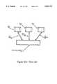
- FIG. 1(a)illustrates an Ethernet network and, specifically, illustrates two network segments.
- Each network segmentcomprises a coaxial cable, e.g., cable 108, and a plurality of nodes or devices, e.g., 101a, 101b and 101c.
- Each nodeis coupled with the coaxial cable through a transceiver cable (such as transceiver cable 102) and a transceiver (such as transceiver 103).
- the transceiveris built directly into the node, or least into a network interface card embodied within the node. This avoids the need for the transceiver cable and allows coupling directly with the coaxial cable.
- the network segmentsare illustrated as being coupled with a repeater module 109 which serves to allow communication between the various network segments.
- a repeater module 109which serves to allow communication between the various network segments.
- a multiport repeater 109is illustrated which allows communication between multiple network segments (however, only two segments are fully illustrated).
- the repeateris coupled with each of the various coaxial cables of the segments through a transceiver and transceiver cable or, more recently, simply through a transceiver embodied in the repeater coupled directly with the coaxial cable.
- all devices coupled with the networkshare a common communication medium with other devices, i.e., the coaxial cable.
- a message originating from any one nodeis communicated to all of the other various devices coupled with the segment (i.e., with the coaxial cable) and, through use of the repeater, the message is also communicated to other devices coupled with other segments of the network.
- this network configurationprovides for communication from one point to multiple other points over a shared media.
- FIG. 1(b)illustrates a central hub 133 in which each of the various nodes 131a, 131b and 131c are coupled to the hub 133 through link segments 132a, 132b and 132c, respectively.
- Link segments 132a, 132b and 132ceach have a transmit and a receive link as illustrated by the Figure.
- a number of such hubsmay be connected together, for example, in either a distributed or hierarchical fashion, to form a larger, enterprise-wide network, thereby providing the capability of communication between nodes coupled to different hubs.
- FIG. 1(c)illustrates an Ethernet controller network interface card 151 which is typically coupled with, for example, the motherboard of a node through interface 153.
- FIG. 1(c)illustrates the central hub 133 which includes a module 156 which allows for coupling with the controller card 151.
- the hub 133is illustrated as being of a modular design, it is not necessary to adopt such a design.
- Each of the controller 151 and module 156typically comprise a wiring jack, 156a and 156b, respectively.
- the jacks 156a and 156ballow coupling of wiring 154 between the controller 151 and module 156.
- this wiring 154comprises relatively inexpensive unshielded twisted pair (UTP) wiring, extra pairs of which are typically installed in most buildings to provide for expanded telephone communication.
- Wiring 154may also be comprised of optical fibers of the kind specified in IEEE standard 802.3j, 10BASE-FL.
- the hub configurationprovides for point-to-point communication between the nodes.
- the communication medium 154is not shared with other devices in the network, although signals on this medium are transmitted to other devices.
- transmission speedsof, for example, 10 Mb/s and 100 Mb/s.
- Thisrefers to the transmission speed of bits of information over the communication medium as distinguished from (1) the effective transmission rate of application level data from an application program running on one node to an application program running on another node, or from (2) the baud rate, which is also referred to as the line transition rate, which may be higher or lower than the bit transmission rate.
- various overhead and other factorsincluding, for example, transmission errors and congestion, cause lower effective bit transmission rates than the transmission rates actually achieved on the medium.
- 10 Mb/s Ethernet systemsutilize Manchester encoding on the communication medium.
- Use of Manchester encodingeffectively requires a baud rate of two times the desired bit transmission rate. Therefore, to achieve a bit transmission rate of 10 Mb/s in a typical Ethernet system utilizing Manchester encoding, a baud of 20 Mbaud is required. Further information on Manchester encoding techniques is available with reference to Madron at pages 60-63.
- the baud rate of conventional Ethernet communication mediamust be increased from 20 Mbaud to 200 Mbaud in order to achieve the desired 100 Mb/s transmission rate. Order of magnitude increases in the baud rate of conventional Ethernet communication media likely will lead to numerous issues including, for example, an increase of RF emissions with respect to regulatory limits.
- Ethernet networksare designed around the concept that a node which wishes to transmit on the network first senses the shared communication medium to determine if it is idle. After having determined the medium is idle, the node may transmit. If two nodes transmit relatively simultaneously, a collision of the information transmitted by both nodes occurs. In such an event, each node continues to transmit a sequence of additional bits called a jam until such time as the collision has propagated to the ends of the network, thus ensuring all nodes in the network are aware a collision has occurred. Each node involved in the collision then waits a random period of time before attempting to again transmit, in an effort to avoid another collision, according to what is referred to by those skilled in the art as a "backoff and retransmission" algorithm.
- a collisionoccurs only during the initial transmission of information from a node until such time as the transmission has propagated to all other nodes in the network. This period of time is referred to as the collision window.
- the collision windowOnce the transmission of information from a node has propagated to all other nodes in the network, i.e., once the collision window has passed, all the other nodes will have sensed the transmission and thereafter yield from transmitting until the communication medium is again idle.
- the transmitting nodedefinitively acquires the communication medium after a period of time equal to the round trip propagation time of the communication medium has expired since the beginning of its own transmission of information.
- nodes which do not have messages to transmitdo not transmit on the medium, although they continue to monitor the medium for packets to be read.
- active nodesnodes which do not have messages to transmit
- data packetsstart with a preamble to allow the various other nodes on the network to acquire and generate receive clock signals which are in phase with the incoming packet. By synchronizing clocks, data may be properly decoded when received.
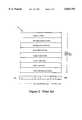
- the 802.3 standardspecifies a format of a frame or "packet structure" 201 for data packets which is more fully described with reference to FIG. 2.
- This packet structure 201is also referred to as the MAC packet structure because it is defined by IEEE 802.3 as part of the Media Access Control (MAC) sublayer derived from the OSI reference model.
- MACMedia Access Control
- the OSI reference modelis a 7 layer conceptual model for networking systems which is well documented in the art.
- the Data Link layeris often discussed as having two sublayers--the MAC or media access control sublayer and LLC or logical link control sublayer. Reference is made to Madron at pages 15-45 for further information on the OSI model.
- the present inventionis primarily concerned with the Physical layer and the MAC sublayer of the Data Link layer of the OSI model.
- the MAC packet structure as defined by the 802.3 standardsincludes substantial overhead.
- the packet structure 201includes a 7 octet (56 bit) preamble that, as has been mentioned, is provided for clocking synchronization between a transmitting node and the receiving nodes.
- the packet structure 201further includes a 1 octet (8 bit) start frame delimiter (SFD) that indicates the start of frame.
- SFDstart frame delimiter
- the minimum packet sizeis 72 octets (the maximum is 1526 octets); therefore it can be seen that the preamble and SFD can constitute as much as over 11 percent of the total packet size (8 octets out of 72).
- the preamble and SFD informationmust be transmitted with every packet, thus requiring 8 octets (64) bits of overhead to be associated with each packet.
- the packet structureincluding for example, the overhead of the preamble and the SFD, has a significant impact on the actual effective transmission rate of application level data from an application program running on one node to an application program running on another node.
- significant changes to the packet structure to improve the actual effective transmission rate of datawould most likely require changes to the MAC sublayer defined by IEEE 802.3.
- an improvement in the method of data transmissionthat does not change the packet structure or further increase the overhead associated with transmitting data is needed.
- the IEEEhas developed standards for use of twisted pair cabling in 802.3 networks.
- the standardsprovide for coupling of two devices (e.g., two data terminals or a data terminal and a repeater) over a twisted pair link comprising two sets of twisted pair wires.
- the twisted pair cablingterminates at a medium attachment unit (MAU) on each of the two devices.
- MAUmedium attachment unit
- Ethernet controller 151may be coupled with central hub 133 over unshielded twisted pair wiring 154.
- the Physical Layeris comprised of the Physical Media Access (PMA) and the Physical Layer Signaling (PLS) sublayer.
- PMAPhysical Media Access
- PLSPhysical Layer Signaling
- the PMAis embedded in the MAU.
- the Physical Layer Signaling (PLS) sublayerprovides for physical and logical coupling between the MAU and the Data Link Layer and, optionally, an Attachment Unit Interface (AUI) which provides for coupling between the MAU and the PLS.
- PLSPhysical Layer Signaling
- FIG. 1(d)logically illustrates aspects of the medium attachment units, 181 and 182, of each of the two devices.
- the Figurefurther illustrates coupling of the MAU with the AUI through differential pairs DO, DI, and CI.
- MAU 181receives signals for transmission on DO 161 from the AUI and proceeds to transmits these signals onto the twisted pair medium over differential pair 171 and 172.
- a positive signalis transmitted with line 171 being positive relative to the signal on line 172.
- a loopback functionis provided within the MAU whereby the signal on DO 161 is provided back on the input DI 163 of the MAU under control of a controller 167.
- Controller 167controls selection of signals for transmission on DI 163. Controller 167 selects either to loopback the signal on DO 161 when data is being transmitted on differential pair 171 and 172 or selects data from receive differential pair 173 and 174. For this purpose, data on receive differential pair 173 and 174 is monitored by controller 167. A collision is detected where there is a simultaneous occurrence of activity on DO 161 and of input data on the receive differential pair 173 and 174.
- MAU 181When not transmitting data received on DO 161, MAU 181 controls output differential pair 171 and 172 to transmit an active idle signal. Likewise, when data is not being received on input differential pair 173 and 174, the circuit expects to receive an active idle signal on this differential pair to assure that the connection with MAU 182 has been maintained.
- twisted pair 802.3 networking systems(often termed 10BASE-T or 802.3i) effectively allows for only half-duplex communication over the twisted pair link segment.
- the receive linesare monitored for the existence of a carrier signal. If carrier is received during transmission it is interpreted as a collision on the link.
- Ethernet controller cards and transceiversIn addition to the constraints imposed by the 802.3 standard, traditional commercial embodiments of the Ethernet controller cards and transceivers often share some internal hardware within the MAC, such as FIFO buffers and CRC generators/checkers, between the input and output paths. This, of course, further restricts these devices to half-duplex transmission.
- the loopback function provided within MAU 181 whereby the signal on DO 161 is provided back on input DI 163 of the MAU under control of controller 167is disabled.
- Controller 167is also disabled such that it cannot detect a simultaneous occurrence of activity on DO 161 and of input data on the receive differential pair 173 and 174, indicating a collision has occurred.
- Disabling the loopback and collision detection functionshas the effect of separating the transmit and receive circuitry of the MAU such that activity on the transmit differential pair 171 and 172 occurs without regard to activity on the receive differential pair 173 and 174, and vise versa, thereby enabling simultaneous transmission and reception of data through MAU 181.
- the disabling of the loopback and collision detection functionscan be accomplished in a number of ways.
- full-duplex communication of datais incorporated into existing 802.3 networks, for example, a 10BASE-T network
- backward compatibilityneeds to exist between newly installed devices supporting full-duplex communication of data and existing devices supporting only half-duplex communication of data, to allow for a smooth migration from half-duplex communication to full-duplex communication of data.
- the newly added devicesshould be capable of communicating data either in full-duplex or half-duplex mode.
- a number of methodshave been employed for a node to switch between half-duplex communication and full-duplex communication, each with their own disadvantages and advantages.
- any method of switching a device between half-duplex to full-duplex communication of datawill involve disabling or enabling the loopback and collision detection circuitry of the MAU coupled thereto.
- the remaining issue, to which the present invention is directed,is the method by which the disabling and enabling of the loopback and collision detection circuitry occurs.
- Prior art methods of switching between half- and full-duplex modeinclude 1) manually operated hardware switches of a MAU, 2) software-controlled switches of a MAU responsive to control signals wherein the control signals are generated by software commands from a node in which the MAU is installed, 3) circuitry located in a node or a MAU attached thereto capable of sending a signal onto the network in accordance with the CSMA/CD protocol indicating the node is capable of full-duplex operation, and additional circuitry located in the node or MAU attached thereto capable of responding to an acknowledgment signal received from the network to enable or disable the loopback and collision detection circuitry.
- a further prior art method of switching between half- and full-duplex modeinvolves what is referred to as physical layer link signaling for auto-negotiation on twisted-pair, or simply, auto-negotiation.
- Auto-negotiationprovides the ability for a device to advertise and request modes of operation of which it is capable to a device at the other end of a point-to-point link as well as receive and acknowledge information regarding modes of operation of which the other device is capable, such that the devices determine the modes of operation supported by each and optimally operate according to those modes shared by both devices.
- Auto-negotiationis performed out of band using a modified 10BASE-T link integrity test pulse sequence (also known as "fast link pulse” or "FLP”) to pass information which identifies the operational modes supported by a device, including, for example, full-duplex communication. This method is described in much greater detail with reference to the aforementioned IEEE Draft Supplement P802.3u/D2 and subsequent drafts.
- the present inventionprovides for effective switching between half-duplex and full-duplex communication of data without the need for any additional hardware switches, software switches or signaling beyond that required for full-duplex communication, or modifications to existing signals required as part of the IEEE 802.3 standard.
- the present inventionprovides a method and apparatus for a node to automatically switch between half-duplex and full-duplex transmission in CSMA/CD networks.
- the present inventionis characterized by a first and second device coupled over a communication link, such as two pairs of twisted pair wires to allow separate communication of information and control signals in each direction between the first and second device.
- a communication linksuch as two pairs of twisted pair wires to allow separate communication of information and control signals in each direction between the first and second device.
- Each of the two devicesinclude a transmit circuit and a receive circuit.
- the present inventionfurther provides a method for transmitting information in a network wherein a first device begins to transmit information on a first communication circuit, the first communication circuit providing for communication of information between the first device and a second device, and the second device receives the transmitted information. If, while the first device is transmitting information to the second device, the second device transmits information (i.e., a packet of legal length according to the protocol) on a second communication circuit, the second communication circuit providing for communication of information between the second device and the first device, and the first device receives the transmitted information, full-duplex communication therebetween is established.
- informationi.e., a packet of legal length according to the protocol
- the second devicetransmits a jam packet, i.e., a packet of collision event length according to the protocol, and the first device receives such a packet, half-duplex communication therebetween is subsequently established.
- a jam packeti.e., a packet of collision event length according to the protocol
- FIG. 1(a)illustrates a known CSMA/CD communication network including two network segments utilizing a coaxial cable.
- FIG. 1(b)illustrates a CSMA/CD communication network organized around a central hub utilizing link segments comprising unshielded twisted pair or fiber cabling.
- FIG. 1(c)illustrates an Ethernet controller card coupled with a central hub over a twisted pair wire connection.
- FIG. 1(d)illustrates further detail of the coupling of FIG. 1(c).
- FIG. 2illustrates a prior art packet and frame format.
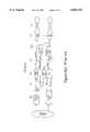
- FIG. 3(a)illustrates a prior art CSMA/CD interface as may be implemented by the present invention.
- FIG. 3(b)illustrates a CSMA/CD interface capable of either full- or half-duplex communication as may be implemented by the present invention.
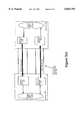
- FIG. 3(c)illustrates a CSMA/CD network, including a block diagram illustration of interfaces at two sides of a transmission link, as may be implemented by the present invention.
- reference numerals in all of the accompanying drawingstypically are in the form "drawing number" followed by two digits, xx; for example, reference numerals on FIG. 1 may be numbered 1xx; on FIG. 2, reference numerals may be numbered 2xx.
- a reference numeralmay be introduced on one drawing and the same reference numeral may be utilized on other drawings to refer to the same item.
- 802.3 networkswhen a device on the point-to-point link is transmitting data on its transmit link and simultaneously receives data (not the idle signal) on its receive link, the device recognizes the event as a collision.
- the point-to-point linkprovides for simultaneous bidirectional communication between the two devices, effectively, this communication is limited to one-way communication of data.
- a recent modification to 802.3 networksinvolves disabling the loopback and collision detection functions of a MAU, thereby enabling two-way communication of data.
- the present inventionprovides for effective switching between half-duplex (one-way) and full-duplex (two-way) communication of data, thereby taking advantage of full-duplex communication of data while at the same time providing backward compatibility with devices capable of only half-duplex communication of data.
- FIG. 3(a)illustrates a network interface of a prior art CSMA/CD system. It is useful to provide a brief overview of such a prior art interface in order to assist in developing an appreciation of the similarities and differences between such a prior art interface and the interface proposed by the preferred embodiment of the present invention.
- the prior art devicecommunicates over a link such as the illustrated unshielded twisted pair (UTP) link.
- This UTP linkcomprises two unshielded twisted pairs of wires, 341 and 342.
- These UTPs 341 and 342couple with MAU 343 of the prior art device and, in particular, the first UTP pair 341 couples with Data Out circuit 346 and the second pair 342 is coupled in communication with Data In circuit 347.
- Pair 342is coupled in communication with the Data In circuit 347 through loopback control circuit 344.
- Data Out circuit 346is provided as a second input to loopback control circuit 344.
- Carrier sense circuit 349provides as an output a signal indicating whether a carrier signal is present on circuit 347. This output is coupled as an input to OR gate 355.
- Data out circuit 346 and Data In circuit 347are both provided as inputs to AND gate 345. If transmission is detected on both circuit 346 and 347, a collision condition is signaled on collision detection line 354. Collision detection line 354, as well as the output of carrier sense circuit 349, are provided as inputs to OR gate 355.
- the output of OR gate 355is provided as a control input to CSMA/CD transmitter 352 of the MAC interface 351.
- the output of AND gate 345is also provided as a control input to transmitter 352.
- the Data In circuit 347is further provided as an input to phase locked loop circuit 348 which provides, as its outputs, both a data signal and a receive clock signal to CSMA/CD receiver 353.
- CSMA/CD receiver 353interfaces as input to higher lever ISO layers 356.
- the higher level ISO layers 356also interface by providing information to CSMA/CD transmitter 352. Assuming carrier is sensed on the receive line (through carrier sense circuit 349) and no collision is sensed, CSMA/CD transmitter is controlled to provide output data to encoder 350 which is then provided on Data Out circuit 346.
- CSMA/CD transmitter 352may be controlled to transmit only when carrier is sensed and a collision is not detected. Therefore, by definition, the interface may only transmit or receive at any given time and the interface does not, therefore, provide a full-duplex interface.
- FIG. 3(b)illustrates the network interface of a device as may be implemented by the present invention.
- the logic diagram illustrated in FIG. 3(b)demonstrates, and is not limited to, one way in which a device and its associated MAU may switch from half-duplex to full-duplex communication of data, or vise versa.
- the interface of the present inventionis designed to interface with a communications link such as the illustrated unshielded twisted pair interface which comprises the two unshielded twisted pairs (UTP) of wires 341 and 342.
- the present inventionprovides for full-duplex communication over the link.
- full-duplex communicationis achieved by disabling the loopback and collision detection circuitry. This can be accomplished, for example, by way of multiplexor 360 and AND gates 363 and 364.
- CSMA/CD-FDX receiver 353deasserts the signals communicated over lines 361 and 362, loopback control circuit 344, carrier sense circuit 349, and collision detection line 354 are disabled.
- Control logic present in CSMA/CD-FDX receiver 353controls the assertion and deassertion of the signals transmitted over lines 361 and 362 to enable or disable the loopback control and collision detect circuitry, thereby controlling switching between half-duplex and full-duplex communication.
- FIG. 3(c)illustrates, conceptually, two devices, 304 and 305, coupled over a point-to-point communications link in which the collision detection and loopback circuitry has been disabled by way of the circuitry discussed in FIG. 3(b), namely, AND gates 363 and 364, multiplexor 360, lines 361 and 362, and control logic in CSMA/CD-FDX receiver 353.
- the devices 304 and 305may comprise, for example, computer workstations, printers, file servers, switching hubs, or other devices.
- device 304may be one of the nodes 131a-131c illustrated by FIG. 1(b), while device 305 may represent one connection of the central hub 133.
- Each of devices 304 and 305comprise a receive circuit 301 and 302, respectively, and a transmit circuit 311 and 312, respectively.
- Receive circuits 301 and 302 and transmit circuits 311 and 312are coupled with a full-duplex communications link 303, which may correspond to one of link segments 132a-132c.
- this link 303may comprise two pairs of twisted pair wiring coupled as in a cross-connected configuration as was described with reference to FIG. 1(d).
- other types of full duplex physical communications mediummay also be utilized, for example, shielded twisted pair wiring, and fiber optics cabling.
- transmit circuit 312 of device 305is coupled to communicate information to receive circuit 301 of device 304 and transmit circuit 311 of device 304 is coupled to communicate information to receive circuit 302 of device 305.
- Each of transmit circuits 311 and 312 and receive circuits 301 and 302are coupled to interface with higher ISO levels executing on their respective devices 304 and 305.
- Link segment 303is logically illustrated as providing for simultaneous bidirectional transmission of data signals 331 from device 304 through transmit circuit 311 to device 305 through receive circuit 302 and data signals 332 from device 305 through transmit circuit 312 to device 304 through receive circuit 301.
- the present inventionmay be implemented by changes to the OSI MAC sublayer and does not require changes to hardware and/or software implementing higher OSI levels.
- the present inventionmay be implemented with minimal changes to existing hardware and software while providing for significant performance enhancements.
- the higher level hardware and softwaremay be used in systems operating according to the present invention or in system implementing conventional technology.
- full-duplex communication of datais incorporated into existing 802.3 networks
- backward compatibilityneeds to exist between newly installed devices having MAUs supporting full-duplex communication of data and existing devices whose MAUs support only half-duplex communication of data, to allow for a smooth migration from half-duplex communication to full-duplex communication of data.
- the newly added devicesshould be capable of communicating data either in full-duplex or half-duplex mode.
- a number of methodshave been employed for a node to switch between half-duplex communication and full-duplex communication, that is, to enable or disable the loopback and collision detection circuitry located therein.
- any method of switching a device between half-duplex to full-duplex communication of datawill involve disabling or enabling the loopback and collision detection circuitry of the MAU coupled thereto. It is the method by which the disabling and enabling of the loopback and collision detection circuitry occurs to which the present invention is directed.
- the method of switching between full-duplex and half-duplex communicationis as follows.
- a device capable of full-duplex communication of data(the full-duplex device) initially powers up ready to perform full-duplex communication.
- CSMA/CD-FDX receiver 353 of the full-duplex deviceinitially deasserts the signals communicated over lines 361 and 362, loopback control circuit 344, carrier sense circuit 349, and collision detection line 354. In so doing, loopback control, collision detect and carrier sense circuitry is disabled, making full-duplex communication possible.
- full-duplex communicationis actually achieved by the full-duplex device depends on the capability of the other device on the other end of the point-to-point link segment. If the other device does not support full-duplex then full-duplex communication between the two devices will not be achieved.
- both devicessupport full-duplex communication
- the processis as follows. Both devices default to full-duplex communication, for example, upon power-up.
- the CSMA/CD-FDX receiver 353 in each devicehas deasserted the signals communicated over lines 361 and 362, loopback control circuit 344, carrier sense circuit 349, and collision detection line 354. No other steps are required. Both devices may transmit and receive data simultaneously.
- full-duplex communicationthat is, simultaneous bidirectional communication, between the two devices is achieved automatically.
- the processis as follows.
- one devicedefaults to full-duplex communication of data on power-up.
- the CSMA/CD receiver in that device(the full-duplex device) has deasserted the signals communicated over lines 361 and 362, loopback control circuit 344, carrier sense circuit 349, and collision detection line 354.
- the other device(the half-duplex device), however, does not support full-duplex communication.
- no negotiation or the likeis attempted between the full-duplex device ready to communicate in full-duplex mode and the half-duplex device able to communicate only in half-duplex mode.
- a connectionis then established between the two devices, for example, as directed by peer upper layers of the OSI model on each device.
- Either devicemay first begin to transmit frames of data to the other device.
- the full-duplex devicemay begin to transmit frames of data to the half-duplex device.
- the half-duplex devicemay then respond by transmitting frames of data to the full-duplex device.
- Communicationmay continue in this manner for some period of time depending on the level and timing of traffic between the full-duplex and half-duplex device, with both devices unaware that the other is operating in a different mode until such time as the full-duplex device transmits a frame of data at the same time the half-duplex device transmits a frame of data, whereupon the half-duplex device collision detection circuitry detects simultaneous transmission and reception of data over UTP pairs 341 and 342, respectively.
- CSMA/CD transmitter circuitry 352 in the half-duplex devicethen properly sends a jam signal and terminates transmission to notify the other device that a collision has occurred.
- the full-duplex devicereceives the collision fragment and recognizes on that basis that the half-duplex device is communicating in half-duplex mode, whereupon it switches to half-duplex communication. Specifically, a valid collision is detected by CSMA/CD-FDX receiver 353 of the full-duplex device. Control logic present in CSMA/CD-FDX receiver 353 of the full-duplex device then asserts the signals communicated over lines 361 and 362, thereby controlling switching from full-duplex to half-duplex communication.
- CSMA/CD-FDX receiver 353 of the full-duplex devicediscerns the difference between a frame of data received from the half-duplex device and a collision on the basis of the size of the frame.
- the minimum frame size of a valid frame of datais 512 bits or 64 octets.
- a collisionis less than 512 bits, (as governed by the slot time, which is based on the maximum round-trip propagational delay time, i.e., the time it takes for a signal to propagate from one end of the link segment and back, plus the size of the jam signal transmitted by the MAC layer upon detection of a collision, performed to notify other devices in the network that a collision has occurred).
- the slot timewhich is based on the maximum round-trip propagational delay time, i.e., the time it takes for a signal to propagate from one end of the link segment and back, plus the size of the jam signal transmitted by the MAC layer upon detection of a collision, performed to notify other devices in the network that a collision has occurred.
- CSMA/CD-FDX receiver 353 of the full-duplex devicereceives a frame of less than 512 bits while communicating in full-duplex mode, it recognizes it as a collision and, on that basis, switches the full-duplex device to half-duplex mode. If, however, the
- a collisionis not only less than 512 bits, but greater than or equal to 96 bits in length.
- CSMA/CD-FDX receiver 353 of the full-duplex devicemay further test for a frame size of less than 96 bits (the number of bit times required for interframe spacing). If a frame is less than 96 bits, it is considered a noise event, not a collision, in which case the full-duplex device remains in full-duplex mode.
- the test for a collisionis if CSMA/CD-FDX receiver 353 of the full-duplex device detects a frame greater than or equal to approximately 96 bits but less than approximately 512 bits, the frame is considered a collision, in which case, the full-duplex device asserts the signals communicated over lines 361 and 362, thereby controlling switching from full-duplex to half-duplex communication.
- the values of 96 bits and 512 bitsrequire slight adjustment for analog system losses.
Landscapes
- Engineering & Computer Science (AREA)
- Computer Networks & Wireless Communication (AREA)
- Signal Processing (AREA)
- Quality & Reliability (AREA)
- Small-Scale Networks (AREA)
Abstract
Description
Claims (27)
Priority Applications (1)
| Application Number | Priority Date | Filing Date | Title |
|---|---|---|---|
| US08/376,125US5825755A (en) | 1994-08-10 | 1995-01-19 | Method and apparatus for switching between full-duplex and half-duplex CSMA/CD systems |
Applications Claiming Priority (2)
| Application Number | Priority Date | Filing Date | Title |
|---|---|---|---|
| US08/288,963US5726976A (en) | 1993-04-06 | 1994-08-10 | Congestion sense controlled access for a star configured network |
| US08/376,125US5825755A (en) | 1994-08-10 | 1995-01-19 | Method and apparatus for switching between full-duplex and half-duplex CSMA/CD systems |
Related Parent Applications (1)
| Application Number | Title | Priority Date | Filing Date |
|---|---|---|---|
| US08/288,963Continuation-In-PartUS5726976A (en) | 1993-04-06 | 1994-08-10 | Congestion sense controlled access for a star configured network |
Publications (1)
| Publication Number | Publication Date |
|---|---|
| US5825755Atrue US5825755A (en) | 1998-10-20 |
Family
ID=23109423
Family Applications (1)
| Application Number | Title | Priority Date | Filing Date |
|---|---|---|---|
| US08/376,125Expired - Fee RelatedUS5825755A (en) | 1994-08-10 | 1995-01-19 | Method and apparatus for switching between full-duplex and half-duplex CSMA/CD systems |
Country Status (1)
| Country | Link |
|---|---|
| US (1) | US5825755A (en) |
Cited By (40)
| Publication number | Priority date | Publication date | Assignee | Title |
|---|---|---|---|---|
| US6011781A (en)* | 1997-03-19 | 2000-01-04 | Advanced Micro Devices, Inc. | Multipoint access protocol utilizing a point-to-point methodology |
| WO2000028684A1 (en)* | 1998-11-06 | 2000-05-18 | Path 1 Network Technologies, Inc. | Time-synchronized multi-layer network switch for providing quality of service guarantees in computer networks |
| US6081523A (en)* | 1997-12-05 | 2000-06-27 | Advanced Micro Devices, Inc. | Arrangement for transmitting packet data segments from a media access controller across multiple physical links |
| US6169729B1 (en)* | 1997-04-08 | 2001-01-02 | Level One Communications, Inc. | 200 Mbps PHY/MAC apparatus and method |
| GB2355373A (en)* | 1999-10-13 | 2001-04-18 | 3Com Corp | Network device with automatic detection of duplex mismatch |
| US6222825B1 (en)* | 1997-01-23 | 2001-04-24 | Advanced Micro Devices, Inc. | Arrangement for determining link latency for maintaining flow control in full-duplex networks |
| US6330248B1 (en)* | 1997-12-05 | 2001-12-11 | Advanced Micro Devices, Inc. | Arrangement for transmitting data packets from a media access controller across multiple physical links |
| US6366567B1 (en)* | 1998-08-06 | 2002-04-02 | Hewlett-Packard Company | Automatic detection of full or half duplex capability in a remote network device |
| US20020083233A1 (en)* | 2000-12-21 | 2002-06-27 | Owen Jonathan M. | System and method of allocating bandwith to a plurality of devices interconnected by a plurality of point-to-point communication links |
| US6600727B1 (en)* | 1999-05-27 | 2003-07-29 | Cisco Technology, Inc. | Distributed network repeater system |
| US20030161348A1 (en)* | 2000-09-28 | 2003-08-28 | Andrew Mills | Method for initializing a link suspend device for optimum receive recovery |
| US6778551B1 (en)* | 1998-10-29 | 2004-08-17 | Samsung Electronics Co., Ltd. | Collision control systems and methods utilizing an inter-frame gap code counter |
| US20040198425A1 (en)* | 2002-10-01 | 2004-10-07 | Mellone Charles M. | Establishing half-duplex audio link as battery saving means |
| KR100478760B1 (en)* | 2002-04-26 | 2005-03-24 | (주)넷비젼텔레콤 | Ethernet frame transmission apparatus using 2 wire lines |
| US20050195746A1 (en)* | 2004-03-05 | 2005-09-08 | Eugene Golovinsky | Method of heuristic determination of network interface transmission mode and apparatus implementing such method |
| US20050213518A1 (en)* | 2004-03-23 | 2005-09-29 | Motorola, Inc. | Mode shifting communications system and method |
| US20060023649A1 (en)* | 2004-07-31 | 2006-02-02 | Daniel Tillet | Subscriber unit capable of switching between full-duplex and half-duplex modes during an on-going session |
| US20060039399A1 (en)* | 2004-08-18 | 2006-02-23 | Takeshi Ejima | Communication device and communication mode setting method |
| US20060056320A1 (en)* | 2004-08-26 | 2006-03-16 | Gatts Todd D | System and process using simplex and duplex communication protocols |
| US20060291602A1 (en)* | 2005-06-23 | 2006-12-28 | Intel Corporation | Communications link clock recovery |
| US20070160087A1 (en)* | 1998-06-02 | 2007-07-12 | Cisco Technology, Inc. | Serial media independent interface |
| US20080170570A1 (en)* | 2007-01-12 | 2008-07-17 | Edward Moskaluk | System and method of switching from multicast to unicast calls |
| US20090034454A1 (en)* | 1995-10-05 | 2009-02-05 | Kubler Joseph J | Hierarchical Data Collection Network Supporting Packetized Voice Communications Among Wireless Terminals and Telephones |
| US20090129583A1 (en)* | 2000-11-29 | 2009-05-21 | Cisco Technology, Inc. A California Corporation | Unpowered twisted pair loopback circuit for differential mode signaling |
| US7539154B1 (en) | 2000-10-17 | 2009-05-26 | Cisco Technology, Inc. | Method and apparatus to detect and break loop configuration |
| US20090213765A1 (en)* | 2005-04-07 | 2009-08-27 | Rinne Mika P | Terminal having a variable duplex capability |
| US20090296609A1 (en)* | 2008-06-02 | 2009-12-03 | Hyung-Nam Choi | Adaptive operational full-duplex and half-duplex FDD modes in wireless networks |
| US7792774B2 (en) | 2007-02-26 | 2010-09-07 | International Business Machines Corporation | System and method for deriving a hierarchical event based database optimized for analysis of chaotic events |
| US7853611B2 (en) | 2007-02-26 | 2010-12-14 | International Business Machines Corporation | System and method for deriving a hierarchical event based database having action triggers based on inferred probabilities |
| US7930262B2 (en) | 2007-10-18 | 2011-04-19 | International Business Machines Corporation | System and method for the longitudinal analysis of education outcomes using cohort life cycles, cluster analytics-based cohort analysis, and probabilistic data schemas |
| US8055603B2 (en) | 2006-10-03 | 2011-11-08 | International Business Machines Corporation | Automatic generation of new rules for processing synthetic events using computer-based learning processes |
| US8145582B2 (en) | 2006-10-03 | 2012-03-27 | International Business Machines Corporation | Synthetic events for real time patient analysis |
| US20120113819A1 (en)* | 2006-04-25 | 2012-05-10 | Tektronix, Inc. | System and Method of Remote Testing in Loopback Mode Using MGCP/NCS |
| US8346802B2 (en) | 2007-02-26 | 2013-01-01 | International Business Machines Corporation | Deriving a hierarchical event based database optimized for pharmaceutical analysis |
| US8712955B2 (en) | 2008-01-02 | 2014-04-29 | International Business Machines Corporation | Optimizing federated and ETL'd databases with considerations of specialized data structures within an environment having multidimensional constraint |
| US20150237301A1 (en)* | 2012-09-27 | 2015-08-20 | Dolby International Ab | Near-end indication that the end of speech is received by the far end in an audio or video conference |
| US9202184B2 (en) | 2006-09-07 | 2015-12-01 | International Business Machines Corporation | Optimizing the selection, verification, and deployment of expert resources in a time of chaos |
| US10318877B2 (en) | 2010-10-19 | 2019-06-11 | International Business Machines Corporation | Cohort-based prediction of a future event |
| US10333686B2 (en) | 2015-05-14 | 2019-06-25 | Apple Inc. | Adaptive half duplex/full duplex operation for battery and antenna constrained devices |
| US20220376818A1 (en)* | 2021-05-18 | 2022-11-24 | Qualcomm Incorporated | Full-duplex control based on dynamic uplink skipping |
Citations (13)
| Publication number | Priority date | Publication date | Assignee | Title |
|---|---|---|---|---|
| US4531238A (en)* | 1981-12-03 | 1985-07-23 | Xerox Corporation | Statistical contention control for star configured communication networks |
| US4630288A (en)* | 1983-12-21 | 1986-12-16 | Motorola Canada Limited | Data transmission with block coding |
| US4759018A (en)* | 1985-06-17 | 1988-07-19 | At&T Bell Laboratories | Higher order digital transmission system including a multiplexer and a demultiplexer |
| US4920533A (en)* | 1987-11-02 | 1990-04-24 | Videotron Ltee | CATV subscriber terminal transmission control |
| US5012467A (en)* | 1989-10-10 | 1991-04-30 | 3Com Corporation | Method and apparatus for collision detection in a local area network transceiver |
| US5119372A (en)* | 1989-05-10 | 1992-06-02 | At&T Bell Laboratories | Multi-access ATD multiplexer with congestion detection circuitry |
| US5121382A (en)* | 1989-10-11 | 1992-06-09 | Digital Equipment Corporation | Station-to-station full duplex communication in a communications network |
| US5249183A (en)* | 1991-03-14 | 1993-09-28 | Level One Communications, Inc. | Interfacing unit for local area networks |
| US5351241A (en)* | 1992-12-24 | 1994-09-27 | Intel Corporation | Twisted pair ethernet hub for a star local area network |
| US5432775A (en)* | 1993-12-03 | 1995-07-11 | Advanced Micro Devices, Inc. | Auto negotiation system for a communications network |
| US5504738A (en)* | 1992-10-27 | 1996-04-02 | Seeq Technology Inc. | Apparatus and method for full-duplex ethernet communications |
| US5541964A (en)* | 1993-08-30 | 1996-07-30 | At&T Corp. | Distortion compensation technique |
| US5572511A (en)* | 1995-01-27 | 1996-11-05 | Tamarack Microelectronics, Inc. | Auto-adjustment circuit for collision detection of ethernet |
- 1995
- 1995-01-19USUS08/376,125patent/US5825755A/ennot_activeExpired - Fee Related
Patent Citations (13)
| Publication number | Priority date | Publication date | Assignee | Title |
|---|---|---|---|---|
| US4531238A (en)* | 1981-12-03 | 1985-07-23 | Xerox Corporation | Statistical contention control for star configured communication networks |
| US4630288A (en)* | 1983-12-21 | 1986-12-16 | Motorola Canada Limited | Data transmission with block coding |
| US4759018A (en)* | 1985-06-17 | 1988-07-19 | At&T Bell Laboratories | Higher order digital transmission system including a multiplexer and a demultiplexer |
| US4920533A (en)* | 1987-11-02 | 1990-04-24 | Videotron Ltee | CATV subscriber terminal transmission control |
| US5119372A (en)* | 1989-05-10 | 1992-06-02 | At&T Bell Laboratories | Multi-access ATD multiplexer with congestion detection circuitry |
| US5012467A (en)* | 1989-10-10 | 1991-04-30 | 3Com Corporation | Method and apparatus for collision detection in a local area network transceiver |
| US5121382A (en)* | 1989-10-11 | 1992-06-09 | Digital Equipment Corporation | Station-to-station full duplex communication in a communications network |
| US5249183A (en)* | 1991-03-14 | 1993-09-28 | Level One Communications, Inc. | Interfacing unit for local area networks |
| US5504738A (en)* | 1992-10-27 | 1996-04-02 | Seeq Technology Inc. | Apparatus and method for full-duplex ethernet communications |
| US5351241A (en)* | 1992-12-24 | 1994-09-27 | Intel Corporation | Twisted pair ethernet hub for a star local area network |
| US5541964A (en)* | 1993-08-30 | 1996-07-30 | At&T Corp. | Distortion compensation technique |
| US5432775A (en)* | 1993-12-03 | 1995-07-11 | Advanced Micro Devices, Inc. | Auto negotiation system for a communications network |
| US5572511A (en)* | 1995-01-27 | 1996-11-05 | Tamarack Microelectronics, Inc. | Auto-adjustment circuit for collision detection of ethernet |
Non-Patent Citations (5)
| Title |
|---|
| ANS/IEEE Standard 802.3, 1993 Edition, Abstract and Table of Contents.* |
| Martin dePrycker, Asynchronous Transfer Mode Solution for Broadband ISDN, 1992, Table of Contents.* |
| Martin dePrycker,"Asynchronous Transfer Mode Solution for Broadband ISDN," 1992, Table of Contents. |
| Thomas W. Madron, "LANS Applications of IEEE/ANSI 802 Standards," 1989, pp. 15-45 and 60-63. |
| Thomas W. Madron, LANS Applications of IEEE/ANSI 802 Standards, 1989, pp. 15 45 and 60 63.* |
Cited By (68)
| Publication number | Priority date | Publication date | Assignee | Title |
|---|---|---|---|---|
| US20090034454A1 (en)* | 1995-10-05 | 2009-02-05 | Kubler Joseph J | Hierarchical Data Collection Network Supporting Packetized Voice Communications Among Wireless Terminals and Telephones |
| US7899007B2 (en)* | 1995-10-05 | 2011-03-01 | Broadcom Corporation | Hierarchical data collection network supporting packetized voice communications among wireless terminals and telephones |
| US6222825B1 (en)* | 1997-01-23 | 2001-04-24 | Advanced Micro Devices, Inc. | Arrangement for determining link latency for maintaining flow control in full-duplex networks |
| US6011781A (en)* | 1997-03-19 | 2000-01-04 | Advanced Micro Devices, Inc. | Multipoint access protocol utilizing a point-to-point methodology |
| US6169729B1 (en)* | 1997-04-08 | 2001-01-02 | Level One Communications, Inc. | 200 Mbps PHY/MAC apparatus and method |
| US6330248B1 (en)* | 1997-12-05 | 2001-12-11 | Advanced Micro Devices, Inc. | Arrangement for transmitting data packets from a media access controller across multiple physical links |
| US6081523A (en)* | 1997-12-05 | 2000-06-27 | Advanced Micro Devices, Inc. | Arrangement for transmitting packet data segments from a media access controller across multiple physical links |
| US20070160087A1 (en)* | 1998-06-02 | 2007-07-12 | Cisco Technology, Inc. | Serial media independent interface |
| US6366567B1 (en)* | 1998-08-06 | 2002-04-02 | Hewlett-Packard Company | Automatic detection of full or half duplex capability in a remote network device |
| US6778551B1 (en)* | 1998-10-29 | 2004-08-17 | Samsung Electronics Co., Ltd. | Collision control systems and methods utilizing an inter-frame gap code counter |
| US6141355A (en)* | 1998-11-06 | 2000-10-31 | Path 1 Network Technologies, Inc. | Time-synchronized multi-layer network switch for providing quality of service guarantees in computer networks |
| WO2000028684A1 (en)* | 1998-11-06 | 2000-05-18 | Path 1 Network Technologies, Inc. | Time-synchronized multi-layer network switch for providing quality of service guarantees in computer networks |
| US7486630B1 (en) | 1999-05-27 | 2009-02-03 | Cisco Technology, Inc. | Module for distributed network repeater |
| US6600727B1 (en)* | 1999-05-27 | 2003-07-29 | Cisco Technology, Inc. | Distributed network repeater system |
| US6973230B1 (en) | 1999-05-27 | 2005-12-06 | Cisco Technology Inc. | Distributed network repeater system |
| US7880474B1 (en) | 1999-05-27 | 2011-02-01 | Cisco Technology Inc. | Distributed network repeater system |
| GB2355373A (en)* | 1999-10-13 | 2001-04-18 | 3Com Corp | Network device with automatic detection of duplex mismatch |
| US6665275B1 (en) | 1999-10-13 | 2003-12-16 | 3Com Corporation | Network device including automatic detection of duplex mismatch |
| GB2355373B (en)* | 1999-10-13 | 2001-10-10 | 3Com Corp | Network device including automatic detection of duplex mismatch |
| US20030161348A1 (en)* | 2000-09-28 | 2003-08-28 | Andrew Mills | Method for initializing a link suspend device for optimum receive recovery |
| US7317691B2 (en)* | 2000-09-28 | 2008-01-08 | Teridian Semiconductor, Corp. | Method for initializing a link suspend device for optimum receive recovery |
| US7539154B1 (en) | 2000-10-17 | 2009-05-26 | Cisco Technology, Inc. | Method and apparatus to detect and break loop configuration |
| US8094808B2 (en)* | 2000-11-29 | 2012-01-10 | Cisco Technology, Inc. | Unpowered twisted pair loopback circuit for differential mode signaling |
| US20090129583A1 (en)* | 2000-11-29 | 2009-05-21 | Cisco Technology, Inc. A California Corporation | Unpowered twisted pair loopback circuit for differential mode signaling |
| US6751684B2 (en)* | 2000-12-21 | 2004-06-15 | Jonathan M. Owen | System and method of allocating bandwidth to a plurality of devices interconnected by a plurality of point-to-point communication links |
| US20020083233A1 (en)* | 2000-12-21 | 2002-06-27 | Owen Jonathan M. | System and method of allocating bandwith to a plurality of devices interconnected by a plurality of point-to-point communication links |
| KR100478760B1 (en)* | 2002-04-26 | 2005-03-24 | (주)넷비젼텔레콤 | Ethernet frame transmission apparatus using 2 wire lines |
| US20040198425A1 (en)* | 2002-10-01 | 2004-10-07 | Mellone Charles M. | Establishing half-duplex audio link as battery saving means |
| US7742423B2 (en)* | 2004-03-05 | 2010-06-22 | Bmc Software, Inc. | Method of heuristic determination of network interface transmission mode and apparatus implementing such method |
| US20050195746A1 (en)* | 2004-03-05 | 2005-09-08 | Eugene Golovinsky | Method of heuristic determination of network interface transmission mode and apparatus implementing such method |
| US7940691B2 (en) | 2004-03-05 | 2011-05-10 | Bmc Software, Inc. | Heuristic determination of network interface transmission mode |
| US20100220625A1 (en)* | 2004-03-05 | 2010-09-02 | Bmc Software, Inc. | Heuristic Determination of Network Interface Transmission Mode |
| EP2469963A3 (en)* | 2004-03-23 | 2014-11-12 | Motorola Mobility LLC | Mode shifting communications system and method |
| US20050213518A1 (en)* | 2004-03-23 | 2005-09-29 | Motorola, Inc. | Mode shifting communications system and method |
| US7230930B2 (en)* | 2004-03-23 | 2007-06-12 | Motorola, Inc. | Mode shifting communications system and method |
| WO2005099122A1 (en) | 2004-03-23 | 2005-10-20 | Motorola, Inc. | Mode shifting communications system and method |
| EP1730855A4 (en)* | 2004-03-23 | 2009-12-16 | Motorola Inc | Mode shifting communications system and method |
| WO2006014912A3 (en)* | 2004-07-31 | 2006-08-17 | Nextel Communications | Subscriber unit capable of switching between full-duplex and half-duplex modes during an on-going session |
| US20060023649A1 (en)* | 2004-07-31 | 2006-02-02 | Daniel Tillet | Subscriber unit capable of switching between full-duplex and half-duplex modes during an on-going session |
| US7974224B2 (en) | 2004-07-31 | 2011-07-05 | Nextel Communications Inc. | Subscriber unit capable of switching between full-duplex and half-duplex modes during an on-going session |
| US20060039399A1 (en)* | 2004-08-18 | 2006-02-23 | Takeshi Ejima | Communication device and communication mode setting method |
| US20060056320A1 (en)* | 2004-08-26 | 2006-03-16 | Gatts Todd D | System and process using simplex and duplex communication protocols |
| US7630330B2 (en)* | 2004-08-26 | 2009-12-08 | International Business Machines Corporation | System and process using simplex and duplex communication protocols |
| US8462671B2 (en)* | 2005-04-07 | 2013-06-11 | Nokia Corporation | Terminal having a variable duplex capability |
| US20090213765A1 (en)* | 2005-04-07 | 2009-08-27 | Rinne Mika P | Terminal having a variable duplex capability |
| US20060291602A1 (en)* | 2005-06-23 | 2006-12-28 | Intel Corporation | Communications link clock recovery |
| US8767563B2 (en)* | 2006-04-25 | 2014-07-01 | Tektronix, Inc. | System and method of remote testing in loopback mode using MGCP/NCS |
| US20120113819A1 (en)* | 2006-04-25 | 2012-05-10 | Tektronix, Inc. | System and Method of Remote Testing in Loopback Mode Using MGCP/NCS |
| US9202184B2 (en) | 2006-09-07 | 2015-12-01 | International Business Machines Corporation | Optimizing the selection, verification, and deployment of expert resources in a time of chaos |
| US8055603B2 (en) | 2006-10-03 | 2011-11-08 | International Business Machines Corporation | Automatic generation of new rules for processing synthetic events using computer-based learning processes |
| US8145582B2 (en) | 2006-10-03 | 2012-03-27 | International Business Machines Corporation | Synthetic events for real time patient analysis |
| US20080170570A1 (en)* | 2007-01-12 | 2008-07-17 | Edward Moskaluk | System and method of switching from multicast to unicast calls |
| US9660827B2 (en)* | 2007-01-12 | 2017-05-23 | Symbol Technologies, Llc | System and method of switching from multicast to unicast calls |
| US7792774B2 (en) | 2007-02-26 | 2010-09-07 | International Business Machines Corporation | System and method for deriving a hierarchical event based database optimized for analysis of chaotic events |
| US8135740B2 (en) | 2007-02-26 | 2012-03-13 | International Business Machines Corporation | Deriving a hierarchical event based database having action triggers based on inferred probabilities |
| US7853611B2 (en) | 2007-02-26 | 2010-12-14 | International Business Machines Corporation | System and method for deriving a hierarchical event based database having action triggers based on inferred probabilities |
| US8346802B2 (en) | 2007-02-26 | 2013-01-01 | International Business Machines Corporation | Deriving a hierarchical event based database optimized for pharmaceutical analysis |
| US7930262B2 (en) | 2007-10-18 | 2011-04-19 | International Business Machines Corporation | System and method for the longitudinal analysis of education outcomes using cohort life cycles, cluster analytics-based cohort analysis, and probabilistic data schemas |
| US8712955B2 (en) | 2008-01-02 | 2014-04-29 | International Business Machines Corporation | Optimizing federated and ETL'd databases with considerations of specialized data structures within an environment having multidimensional constraint |
| US20090296609A1 (en)* | 2008-06-02 | 2009-12-03 | Hyung-Nam Choi | Adaptive operational full-duplex and half-duplex FDD modes in wireless networks |
| US8542617B2 (en)* | 2008-06-02 | 2013-09-24 | Apple Inc. | Adaptive operational full-duplex and half-duplex FDD modes in wireless networks |
| US10318877B2 (en) | 2010-10-19 | 2019-06-11 | International Business Machines Corporation | Cohort-based prediction of a future event |
| US20150237301A1 (en)* | 2012-09-27 | 2015-08-20 | Dolby International Ab | Near-end indication that the end of speech is received by the far end in an audio or video conference |
| US9525845B2 (en)* | 2012-09-27 | 2016-12-20 | Dobly Laboratories Licensing Corporation | Near-end indication that the end of speech is received by the far end in an audio or video conference |
| US10333686B2 (en) | 2015-05-14 | 2019-06-25 | Apple Inc. | Adaptive half duplex/full duplex operation for battery and antenna constrained devices |
| US11190330B2 (en) | 2015-05-14 | 2021-11-30 | Apple Inc. | Adaptive half duplex / full duplex operation for battery and antenna constrained devices |
| US20220376818A1 (en)* | 2021-05-18 | 2022-11-24 | Qualcomm Incorporated | Full-duplex control based on dynamic uplink skipping |
| US11569932B2 (en)* | 2021-05-18 | 2023-01-31 | Qualcomm Incorporated | Full-duplex control based on dynamic uplink skipping |
Similar Documents
| Publication | Publication Date | Title |
|---|---|---|
| US5825755A (en) | Method and apparatus for switching between full-duplex and half-duplex CSMA/CD systems | |
| US5726976A (en) | Congestion sense controlled access for a star configured network | |
| US5432775A (en) | Auto negotiation system for a communications network | |
| EP0772326B1 (en) | Full duplex flow control for ethernet networks | |
| US6198722B1 (en) | Flow control method for networks | |
| EP0830768B1 (en) | Enhancements to 802.3 media access control and associate signaling schemes for full duplex ethernet | |
| US6192422B1 (en) | Repeater with flow control device transmitting congestion indication data from output port buffer to associated network node upon port input buffer crossing threshold level | |
| US7065075B1 (en) | Reduced pin gigabit media independent interface | |
| EP0966128B1 (en) | Apparatus and method of determining a link status between network stations connected to a telephone line medium | |
| US5940401A (en) | Carrier extension for gigabit/second ethernet networks operable up to at least 200 m distances | |
| EP0830769A1 (en) | Flow control method and apparatus for ethernet packet switched hub | |
| JPH0637765A (en) | Network connecting system, data processing network and its operating method | |
| JPH05219088A (en) | Communication network control method | |
| EP0904645B1 (en) | Rotating priority arrangement in an ethernet network | |
| US20090245120A1 (en) | Ethernet Physical Layer Transceiver with Auto-Ranging Function | |
| US20040199834A1 (en) | Transceiver circuit, transceiving method, and transceiver apparatus | |
| US6778551B1 (en) | Collision control systems and methods utilizing an inter-frame gap code counter | |
| US6370115B1 (en) | Ethernet device and method for applying back pressure | |
| US6009104A (en) | Apparatus and method for selectively modulating interpacket gap interval following a collision to avoid capture effect | |
| US20030058841A1 (en) | Anti-offline device adapted to be used in home PNA compliant network system and the data packet transmission method thereof | |
| Jain | Recent Advances in 100 Mbps LAN Technologies | |
| Buchanan | Local Area Networks (Ethernet) | |
| Buchanan | Ethernet | |
| KR20010026669A (en) | Method for providing inter-frame gap time |
Legal Events
| Date | Code | Title | Description |
|---|---|---|---|
| AS | Assignment | Owner name:SYNOPTICS COMMUNICATIONS, INC., CALIFORNIA Free format text:ASSIGNMENT OF ASSIGNORS INTEREST;ASSIGNORS:THOMPSON, GEOFFREY O.;WOODRUFF, PAUL;REEL/FRAME:007316/0217 Effective date:19950116 | |
| AS | Assignment | Owner name:BAY NETWORKS, INC., CALIFORNIA Free format text:CHANGE OF NAME;ASSIGNOR:SYNOPTICS COMMUNICATIONS, INC.;REEL/FRAME:009210/0239 Effective date:19950110 | |
| AS | Assignment | Owner name:BAY NETWORKS GROUP, INC., CALIFORNIA Free format text:CHANGE OF NAME;ASSIGNOR:SYNOPTICS COMMUNICATIONS, INC.;REEL/FRAME:010949/0471 Effective date:19950110 | |
| FEPP | Fee payment procedure | Free format text:PAYOR NUMBER ASSIGNED (ORIGINAL EVENT CODE: ASPN); ENTITY STATUS OF PATENT OWNER: LARGE ENTITY | |
| FEPP | Fee payment procedure | Free format text:PAYER NUMBER DE-ASSIGNED (ORIGINAL EVENT CODE: RMPN); ENTITY STATUS OF PATENT OWNER: LARGE ENTITY Free format text:PAYOR NUMBER ASSIGNED (ORIGINAL EVENT CODE: ASPN); ENTITY STATUS OF PATENT OWNER: LARGE ENTITY | |
| AS | Assignment | Owner name:NORTEL NETWORKS GROUP INC., CALIFORNIA Free format text:CHANGE OF NAME;ASSIGNOR:BAY NETWORKS GROUP, INC.;REEL/FRAME:012475/0142 Effective date:19990420 | |
| FPAY | Fee payment | Year of fee payment:4 | |
| AS | Assignment | Owner name:NORTEL NETWORKS GROUP INC., CALIFORNIA Free format text:CHANGE OF NAME;ASSIGNOR:BAY NETWORKS GROUP, INC.;REEL/FRAME:013403/0973 Effective date:19990420 | |
| AS | Assignment | Owner name:NORTEL NETWORKS NA INC., CALIFORNIA Free format text:CERTIFICATE OF OWNERSHIP;ASSIGNOR:NORTEL NETWORKS GROUP INC.;REEL/FRAME:013653/0554 Effective date:19991221 | |
| AS | Assignment | Owner name:NORTEL NETWORKS INC., CANADA Free format text:ASSIGNMENT OF ASSIGNORS INTEREST;ASSIGNOR:NORTEL NETWORKS NA INC.;REEL/FRAME:013735/0970 Effective date:20001231 | |
| AS | Assignment | Owner name:NORTEL NETWORKS LIMITED, CANADA Free format text:ASSIGNMENT OF ASSIGNORS INTEREST;ASSIGNOR:NORTEL NETWORKS INC.;REEL/FRAME:013751/0653 Effective date:20030619 | |
| FPAY | Fee payment | Year of fee payment:8 | |
| REMI | Maintenance fee reminder mailed | ||
| LAPS | Lapse for failure to pay maintenance fees | ||
| STCH | Information on status: patent discontinuation | Free format text:PATENT EXPIRED DUE TO NONPAYMENT OF MAINTENANCE FEES UNDER 37 CFR 1.362 | |
| FP | Lapsed due to failure to pay maintenance fee | Effective date:20101020 |