US5825045A - Extended range highly selective low power consuming data tag and information display system - Google Patents
Extended range highly selective low power consuming data tag and information display systemDownload PDFInfo
- Publication number
- US5825045A US5825045AUS08/901,389US90138997AUS5825045AUS 5825045 AUS5825045 AUS 5825045AUS 90138997 AUS90138997 AUS 90138997AUS 5825045 AUS5825045 AUS 5825045A
- Authority
- US
- United States
- Prior art keywords
- data
- light beam
- tag
- data tag
- infrared
- Prior art date
- Legal status (The legal status is an assumption and is not a legal conclusion. Google has not performed a legal analysis and makes no representation as to the accuracy of the status listed.)
- Expired - Fee Related
Links
Images


Classifications
- G—PHYSICS
- G06—COMPUTING OR CALCULATING; COUNTING
- G06K—GRAPHICAL DATA READING; PRESENTATION OF DATA; RECORD CARRIERS; HANDLING RECORD CARRIERS
- G06K19/00—Record carriers for use with machines and with at least a part designed to carry digital markings
- G06K19/06—Record carriers for use with machines and with at least a part designed to carry digital markings characterised by the kind of the digital marking, e.g. shape, nature, code
- G06K19/067—Record carriers with conductive marks, printed circuits or semiconductor circuit elements, e.g. credit or identity cards also with resonating or responding marks without active components
- G06K19/07—Record carriers with conductive marks, printed circuits or semiconductor circuit elements, e.g. credit or identity cards also with resonating or responding marks without active components with integrated circuit chips
- G06K19/0723—Record carriers with conductive marks, printed circuits or semiconductor circuit elements, e.g. credit or identity cards also with resonating or responding marks without active components with integrated circuit chips the record carrier comprising an arrangement for non-contact communication, e.g. wireless communication circuits on transponder cards, non-contact smart cards or RFIDs
- G06K19/0728—Record carriers with conductive marks, printed circuits or semiconductor circuit elements, e.g. credit or identity cards also with resonating or responding marks without active components with integrated circuit chips the record carrier comprising an arrangement for non-contact communication, e.g. wireless communication circuits on transponder cards, non-contact smart cards or RFIDs the arrangement being an optical or sound-based communication interface
- G—PHYSICS
- G06—COMPUTING OR CALCULATING; COUNTING
- G06K—GRAPHICAL DATA READING; PRESENTATION OF DATA; RECORD CARRIERS; HANDLING RECORD CARRIERS
- G06K19/00—Record carriers for use with machines and with at least a part designed to carry digital markings
- G06K19/06—Record carriers for use with machines and with at least a part designed to carry digital markings characterised by the kind of the digital marking, e.g. shape, nature, code
- G06K19/067—Record carriers with conductive marks, printed circuits or semiconductor circuit elements, e.g. credit or identity cards also with resonating or responding marks without active components
- G06K19/07—Record carriers with conductive marks, printed circuits or semiconductor circuit elements, e.g. credit or identity cards also with resonating or responding marks without active components with integrated circuit chips
- G06K19/0723—Record carriers with conductive marks, printed circuits or semiconductor circuit elements, e.g. credit or identity cards also with resonating or responding marks without active components with integrated circuit chips the record carrier comprising an arrangement for non-contact communication, e.g. wireless communication circuits on transponder cards, non-contact smart cards or RFIDs
- G—PHYSICS
- G06—COMPUTING OR CALCULATING; COUNTING
- G06K—GRAPHICAL DATA READING; PRESENTATION OF DATA; RECORD CARRIERS; HANDLING RECORD CARRIERS
- G06K7/00—Methods or arrangements for sensing record carriers, e.g. for reading patterns
- G06K7/10—Methods or arrangements for sensing record carriers, e.g. for reading patterns by electromagnetic radiation, e.g. optical sensing; by corpuscular radiation
- G06K7/10544—Methods or arrangements for sensing record carriers, e.g. for reading patterns by electromagnetic radiation, e.g. optical sensing; by corpuscular radiation by scanning of the records by radiation in the optical part of the electromagnetic spectrum
- G06K7/10821—Methods or arrangements for sensing record carriers, e.g. for reading patterns by electromagnetic radiation, e.g. optical sensing; by corpuscular radiation by scanning of the records by radiation in the optical part of the electromagnetic spectrum further details of bar or optical code scanning devices
- G06K7/1097—Optical sensing of electronic memory record carriers, such as interrogation of RFIDs with an additional optical interface
- G—PHYSICS
- G06—COMPUTING OR CALCULATING; COUNTING
- G06K—GRAPHICAL DATA READING; PRESENTATION OF DATA; RECORD CARRIERS; HANDLING RECORD CARRIERS
- G06K2207/00—Other aspects
- G06K2207/1011—Aiming
Definitions
- This inventionrelates to the field of automatic identification, and particularly to solid state records such as so called tags which may store data which can be interrogated or modified via a wireless link, typically with the use of a hand-held device.
- Bar codesare useful for identifying and maintaining inventory for a variety of products and goods.
- One of the disadvantages of a bar code systemis that it may be difficult to read, depending on ambient light availability, and the bar codes position in relation to the reader.
- radio frequency transponderswhich require contact with a reader in order to be read.
- radio frequency tag magnetic readersin which no contact is required. These magnetic RF tags may be read by a reader which activates a transmitter within an RF tag whenever the RF tag becomes disposed within the electromagnetic field generated by the RF tag reader. This causes a radio frequency signal to be transmitted which may then be received by the reader.
- a typical prior art systemutilizes an RF tag which when interrogated by RF energy from a hand-held unit, emits an RF signal serving to provide an identification of a product with which the tag is associated.
- a preferred embodiment of the present inventionis based on the use of a visible light beam to activate or interrogate a solid state record, herein referred to as a data tag so as to reflect its antecedent in the RF tag art.
- a desired data tagcan be selected from other adjacent data tags by directing a laser beam so as to impinge on the selected tag.
- the tagis light sensitive, and selective to the wavelength of the laser beam, impingement of the beam can activate the data tag, e.g., to transmit its data wirelessly as with the conventional RF tag.
- the energy of the laser beamcan provide operating power for the data tag, e.g. the intensity of the tag response signal being proportional to the duration of the incidence of the laser beam to minimize the production of, e.g., RF noise in the environment.
- the laser light beam when directed to impinge on the data tagcan adjust its spot size relative to the photosensitive area of the data tag so as to insure steady coupling and then be modulated to e.g. modify stored data in the data tag.
- the system of the present inventioncan use, e.g., a laser beam to select a given information display record or data tag and to modify the display as desired.
- the data tagcan store product identification data which can be wirelessly interrogated (e.g., by a command signal transmitted by the laser beam), and can thus respond to a hand-held terminal device for inventory or reordering purposes.
- the photosensitive region of the data tagcould be also sensitive to ambient light, e.g. retail store lighting, so as to store operating power.
- a readerhaving a size and a shape which may be hand-held and is operably attached to a separate hand-held or pocket sized or belt attached or the like terminal for receiving, processing and storing information.
- the terminalmay be hard wired or RF linked to the reader such that it may be utilized independently for other purposes when it is not operably coupled with an RF tag reader.
- a conventional bar code readermay also be operably coupled with the terminal if desired.
- the data tagis at least partially powered by the radiant energy beam of the tag reader unit such that the data tag is both activated and powered by the tag reader unit.
- FIG. 1is a diagrammatic elevational view showing adjoining stacks of articles with solid state records or data tags thereon which store product identification information for wireless transmission to a reader device in response to impingement of a laser beam of a given wavelength from the reader unit impinging upon a selected tag;
- FIG. 2is a diagrammatic side elevational view showing a data tag such as those illustrated in FIG. 1 with a photosensitive surface receiving an interrogating laser beam, and responsive thereto for wirelessly transmitting its stored data e.g. via an infrared, acoustic or RF transmitter;
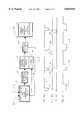
- FIG. 3is a diagrammatic block diagram indicating functional components of the solid state circuit imbedded in the data tag of FIGS. 1 and 2;
- FIGS. 4A and 4Billustrate a preferred method of two-way communication between the reader unit and the data tag
- FIG. 4Ashowing the periodic transmission of visible laser light energy to the data tag
- FIG. 4Bshowing an exemplary location of a communication aperture or time window which has a given time duration and a given time spacing from the waveform of FIG. 4A
- FIG. 4Cillustrates the presence of a data pulse generated by the data tag within the time window of FIG. 4B, e.g. for representing a binary one data bit during such time window;
- FIG. 5illustrates the case where the "on" intervals of FIG. 4A are reduced, causing reduced energy transfer from the laser beam to the data tag, and consequent reduced intensity of the return data pulse from the data tag;
- FIG. 6illustrates an embodiment of the present invention which provides a data tag at least partially powered by the radiant energy beam of the tag reader unit such that the data tag is both activated and powered by the tag reader unit.
- FIGS. 1 through 11 of U.S. Pat. No. 5,280,159, issued Jan. 18, 1994,are hereby incorporated herein by reference.
- FIG. 1shows a series of stacks such as 10, 11 and 12 rising vertically from support surfaces such as indicated at 14.
- a first stack 10may comprise identical products 16 with respective identifying data tags 16A.
- a second stack 11may comprise respective identical articles 17 with respective identical identifying data tags 17A, while a third stack 12 may comprise respective identical articles 18 with identical identifying data tags 18A.
- a tag readeris provided with a laser beam source which produces a laser beam of size to conveniently select a desired data tag from different adjoining data tags.
- a spot from a laser beam tag readerdoes not greatly exceed the size of the entire data tag such as 17A, and further the laser beam is preferably of a visible wavelength, so that the spot 20 is readily visible to the user who is aiming the tag reader device.
- each data tag such as 17Ais provided with a photosensitive surface area such as diagrammatically indicated at 22 and which may comprise a major portion of the surface of tag 17A as viewed in FIG. 1.
- the tagis shown provided with a transmitter diagrammatically indicated at 24.
- a laser beamsuch as indicated at 20A is incident anywhere within the sensitive area 22, this may activate the data tag for example to transmit identifying data as indicated at 26, such data for example identifying the product 17 and differentiating such product from other products such as 16 and 18.
- the transmitter 24provides wireless coupling with the reader unit, and may for example be an infrared, acoustic, or RF transmitter.
- the readermay have a gun configuration such as is common in the laser bar code scanner art with a trigger controlling a laser diode or other preferably visible light laser source for projecting the beam 20A.
- the reader unit 30is provided with a trigger as indicated at 31 and may have a window as indicated at 32 through which the beam 20A is emitted longitudinally so as to facilitate proprioceptive directing of the reader unit 31 by the user, or if desired, actual visual sighting, where the unit 30 is raised to shoulder height or the like and the user actually sights along the barrel of the unit.
- An infrared return signalmay be relatively omnidirectional, and, for example, the same window 32 may have a sufficient area to receive a substantial amount of the return signal energy which is then suitably optically concentrated and focused onto an optical e.g. infrared detector.
- a portion of the window 32may be replaced with an acoustical transducer for receiving the return acoustic signal.
- the unit 30may have an external or internal antenna, and in this respect may correspond with a conventional RF tag unit.
- FIG. 3shows the example of a data tag 17A with a photosensitive surface 22 which is not only sensitive to the wavelength of laser beam 22A, but is also suitable for converting ambient light surrounding the data tag and impinging on the data tag as represented by arrow 41 to produce operating power as indicated by arrow 42, for example, for storage to maintain a suitable integrated circuit memory such as RAM component 43.
- the laser beammay be amplitude modulated at a suitable frequency, and a frequency selective circuit 50 may respond to such modulated laser light energy to transmit a signal to a processor system such as microprocessor 51.
- a response driver component 54which activates a transmitter 55 of one of the types previously mentioned.
- Components 43, 50, 51, 54 and 55may all be part of a relatively small solid state device such as represented by the data tags 16A, 17A and 18A in FIG. 1.
- FIG. 4Ashows the case where the e.g. amplitude modulated laser beam while aligned with a given tag is periodically turned off at intervals 61, 62 and 63 so as to initiate a timing cycle e.g. within processor circuit 51 and within the reader unit itself, resulting in the definition of a desired communication window as represented at 61A in FIG. 4B during which one data bit may be transmitted by components 51, 54 and 55.
- the window 61Amay have a time duration of one hundred nanoseconds
- a pulse 70, FIG. 4C, generated by the data tagmay have a duration of twenty nanoseconds and be located within the time window 61A for presence of a binary one in the particular data frame represented by pulse 61 and window 61A.
- FIG. 6illustrates an information transducing system 100 wherein the data tag 102 is at least partially powered by the tag reader unit 104 radiant energy beams (106A, 106B).
- the data tag 102includes a rare earth (preferably Erbium) doped optical material 108.
- the tag reader unit 104includes a first laser light source 106A capable of generating a first radiant energy beam 108A (preferably with a frequency in the green range), and a second laser light source 106B capable of generating a second radiant energy beam 108B (preferably with a frequency in the infrared range).
- the data tag 102includes an erbium doped optical material (or other suitable rare earth material) 110, a digital memory 114, and a radio frequency transmitter 116 (a photovoltaic cell 112 may also be provided).
- the first laser 106Aoperates at a characteristic frequency in the green range.
- the second laser 106Boperates in the infrared range.
- the green laserprovides photons that are more energetic than the infrared laser. (The photon energy is the product of the frequency and Planck's constant, thus, an increase in frequency will produce an increased photon energy level).
- the erbiumabsorbs some of the higher elevated energetic states that are metastable establishing a population inversion. These erbium atoms have at least two routes they may take to reach their ground state. They may directly emit light at the same wavelength they absorbed or they can emit light at intermediate frequencies making at least two emissions to reach their ground state. These allowed frequencies are well defined and not arbitrary. Preferably the infrared laser frequency just matches one of these allowed emission
- the erbium doped optical material 110is exposed to two incoming laser beams, energetically appropriate and of the correct allowed frequency, an interesting phenomenon predicted by Einstein takes place.
- the lower frequency infrared beamstimulates infrared emission from the metastable erbium atoms.
- This emitted lightis coherent and directed in the same direction as the incident stimulating infrared beam.
- a responder made of erbium doped optical material and backed by a mirrormay be utilized to achieve an optical gain and reradiate more energy in the infrared back to the tag reader unit 104 than is incident upon it. This optical gain may be detected by a receiver 120.
- the respondermay encode reradiated emissions by means of masks and polarizing filters.
Landscapes
- Engineering & Computer Science (AREA)
- Physics & Mathematics (AREA)
- Theoretical Computer Science (AREA)
- General Physics & Mathematics (AREA)
- Microelectronics & Electronic Packaging (AREA)
- Computer Hardware Design (AREA)
- Computer Networks & Wireless Communication (AREA)
- Electromagnetism (AREA)
- Health & Medical Sciences (AREA)
- General Health & Medical Sciences (AREA)
- Toxicology (AREA)
- Artificial Intelligence (AREA)
- Computer Vision & Pattern Recognition (AREA)
- Optical Communication System (AREA)
Abstract
Description
Claims (17)
Priority Applications (1)
| Application Number | Priority Date | Filing Date | Title |
|---|---|---|---|
| US08/901,389US5825045A (en) | 1992-02-13 | 1997-07-28 | Extended range highly selective low power consuming data tag and information display system |
Applications Claiming Priority (4)
| Application Number | Priority Date | Filing Date | Title |
|---|---|---|---|
| US83602492A | 1992-02-13 | 1992-02-13 | |
| US18463694A | 1994-01-18 | 1994-01-18 | |
| US50356995A | 1995-07-18 | 1995-07-18 | |
| US08/901,389US5825045A (en) | 1992-02-13 | 1997-07-28 | Extended range highly selective low power consuming data tag and information display system |
Related Parent Applications (1)
| Application Number | Title | Priority Date | Filing Date |
|---|---|---|---|
| US50356995AContinuation | 1992-02-13 | 1995-07-18 |
Publications (1)
| Publication Number | Publication Date |
|---|---|
| US5825045Atrue US5825045A (en) | 1998-10-20 |
Family
ID=27391867
Family Applications (1)
| Application Number | Title | Priority Date | Filing Date |
|---|---|---|---|
| US08/901,389Expired - Fee RelatedUS5825045A (en) | 1992-02-13 | 1997-07-28 | Extended range highly selective low power consuming data tag and information display system |
Country Status (1)
| Country | Link |
|---|---|
| US (1) | US5825045A (en) |
Cited By (52)
| Publication number | Priority date | Publication date | Assignee | Title |
|---|---|---|---|---|
| WO2001031600A1 (en)* | 1999-10-26 | 2001-05-03 | Paolo Borlenghi | System for identifying a personal item, such as an item of clothing, an accessory or a portable device |
| WO2001099040A3 (en)* | 2000-06-21 | 2002-04-04 | Atlantes Services Inc | Bidirectional barcode scanning system |
| US6393045B1 (en)* | 1997-09-26 | 2002-05-21 | Wherenet Corp. | Spread spectrum baseband modulation of magnetic fields for communications and proximity sensing |
| US6415978B1 (en)* | 1999-05-03 | 2002-07-09 | Psc Scanning, Inc. | Multiple technology data reader for bar code labels and RFID tags |
| EP1103824A3 (en)* | 1999-11-23 | 2002-08-28 | Xerox Corporation | Virtual control system using non-imaging scanners |
| US6542083B1 (en) | 1999-11-23 | 2003-04-01 | Xerox Corporation | Electronic tag position detection using radio broadcast |
| EP1315133A1 (en)* | 2001-11-22 | 2003-05-28 | Sony International (Europe) GmbH | Mobile transmitting device for transmitting messages in a beamed way |
| EP1107161A3 (en)* | 1999-12-10 | 2003-06-04 | VLG Virtual Laser Systems GmbH | Circuit for signal response |
| US20040027455A1 (en)* | 2000-12-15 | 2004-02-12 | Leonard Reiffel | Imaged coded data source tracking product |
| US20040041027A1 (en)* | 2000-12-15 | 2004-03-04 | Leonard Reiffel | Imaged coded data source transducer product |
| US20040125224A1 (en)* | 2000-08-18 | 2004-07-01 | Leonard Reiffel | Annotating imaged data product |
| US20040135766A1 (en)* | 2001-08-15 | 2004-07-15 | Leonard Reiffel | Imaged toggled data input product |
| US20040188525A1 (en)* | 2000-05-03 | 2004-09-30 | Leonard Reiffel | Dual mode data imaging product |
| WO2004100058A1 (en)* | 2003-05-12 | 2004-11-18 | Valtion Teknillinen Tutkimuskeskus | Remote sensor, device and method for activating selected remote sensor components |
| US6830181B1 (en)* | 1998-02-09 | 2004-12-14 | Intermec Ip Corp. | Combined optical and radio frequency tag reader |
| WO2004090800A3 (en)* | 2003-04-14 | 2004-12-23 | Giesecke & Devrient Gmbh | Contactless data carrier |
| US20050040241A1 (en)* | 2003-08-19 | 2005-02-24 | Ramesh Raskar | Radio and optical identification tags |
| FR2860625A1 (en)* | 2003-10-01 | 2005-04-08 | Commissariat Energie Atomique | OPTICAL IDENTIFICATION LABEL ADDRESSABLE BY A PLAYBACK UNIT |
| US20050102332A1 (en)* | 2000-12-15 | 2005-05-12 | Leonard Reiffel | Multi-imager multi-source multi-use coded data source data iInput product |
| US20050116813A1 (en)* | 2003-08-19 | 2005-06-02 | Ramesh Raskar | Radio and optical identification tags |
| US7034803B1 (en) | 2000-08-18 | 2006-04-25 | Leonard Reiffel | Cursor display privacy product |
| US20060127097A1 (en)* | 2004-12-14 | 2006-06-15 | Pitney Bowes Incorporated | Utilizing a laser to securely communicate with radio frequency identification tags |
| US20060138225A1 (en)* | 1999-11-23 | 2006-06-29 | Richley Edward A | Laser locating and tracking system for externally activated tags |
| US20060187050A1 (en)* | 2005-02-11 | 2006-08-24 | Psc Scanning, Inc. | Loop antenna for RFID |
| US7137711B1 (en) | 2000-03-21 | 2006-11-21 | Leonard Reiffel | Multi-user retro reflector data input |
| US20060261951A1 (en)* | 2005-04-26 | 2006-11-23 | Rf Code, Inc. | RFID systems and methods employing infrared localization |
| US20060291797A1 (en)* | 2003-05-27 | 2006-12-28 | Leonard Reiffel | Multi-imager multi-source multi-use coded data source data input product |
| US7207486B1 (en)* | 1998-02-09 | 2007-04-24 | Intermec Ip Corp. | Combined optical and radio frequency tag reader |
| US20070187506A1 (en)* | 2001-04-19 | 2007-08-16 | Leonard Reiffel | Combined imaging coded data source data acquisition |
| US20070287134A1 (en)* | 2006-05-26 | 2007-12-13 | Chung Bobby H | System and Method to Minimize Laser Misalignment Error in a Firearms Training Simulator |
| US20080030305A1 (en)* | 2006-05-16 | 2008-02-07 | O'connor Ruaidhri M | Systems and Methods for Using a Tag |
| US20090294535A1 (en)* | 2004-12-10 | 2009-12-03 | Koninklijke Philips Electronics N.V. | Data carrier with a chip and a plurality of sensors |
| US20090314829A1 (en)* | 2007-05-22 | 2009-12-24 | Mcallistor Clarke | Systems, Methods, and Devices for Replication of Data onto Wireless Sensors |
| USD626949S1 (en) | 2008-02-20 | 2010-11-09 | Vocollect Healthcare Systems, Inc. | Body-worn mobile device |
| US20100283584A1 (en)* | 2005-08-19 | 2010-11-11 | Mcallister Clarke William | Systems, Methods, and Devices for Commissioning Wireless Sensors. |
| US20110091216A1 (en)* | 2009-10-20 | 2011-04-21 | Ken Addy | Long range selective rfid using laser photodetection wakeup |
| USD643013S1 (en) | 2010-08-20 | 2011-08-09 | Vocollect Healthcare Systems, Inc. | Body-worn mobile device |
| USD643400S1 (en) | 2010-08-19 | 2011-08-16 | Vocollect Healthcare Systems, Inc. | Body-worn mobile device |
| US8128422B2 (en) | 2002-06-27 | 2012-03-06 | Vocollect, Inc. | Voice-directed portable terminals for wireless communication systems |
| US8386261B2 (en) | 2008-11-14 | 2013-02-26 | Vocollect Healthcare Systems, Inc. | Training/coaching system for a voice-enabled work environment |
| US8618998B2 (en) | 2009-07-21 | 2013-12-31 | Applied Wireless Identifications Group, Inc. | Compact circular polarized antenna with cavity for additional devices |
| US8659397B2 (en) | 2010-07-22 | 2014-02-25 | Vocollect, Inc. | Method and system for correctly identifying specific RFID tags |
| US20150022321A1 (en)* | 2013-07-17 | 2015-01-22 | Donald Keith Lefevre | Long-Range Electronic Identification System |
| US9272805B2 (en) | 2005-08-19 | 2016-03-01 | Adasa Inc. | Systems, methods, and devices for commissioning wireless sensors |
| US20170181401A1 (en)* | 2013-07-17 | 2017-06-29 | Donald Keith Lefevre | Long-Range Electronic Identification System |
| US9747480B2 (en) | 2011-12-05 | 2017-08-29 | Adasa Inc. | RFID and robots for multichannel shopping |
| US9780435B2 (en) | 2011-12-05 | 2017-10-03 | Adasa Inc. | Aerial inventory antenna |
| US10050330B2 (en) | 2011-12-05 | 2018-08-14 | Adasa Inc. | Aerial inventory antenna |
| US20190005289A1 (en)* | 2017-06-29 | 2019-01-03 | Samsung Sds Co., Ltd. | Image code recognition apparatus |
| US10476130B2 (en) | 2011-12-05 | 2019-11-12 | Adasa Inc. | Aerial inventory antenna |
| US10846497B2 (en) | 2011-12-05 | 2020-11-24 | Adasa Inc. | Holonomic RFID reader |
| US11093722B2 (en) | 2011-12-05 | 2021-08-17 | Adasa Inc. | Holonomic RFID reader |
Citations (4)
| Publication number | Priority date | Publication date | Assignee | Title |
|---|---|---|---|---|
| US4242663A (en)* | 1979-02-01 | 1980-12-30 | Lockheed Electronics Corporation | Electronic identification system |
| US4658147A (en)* | 1985-04-03 | 1987-04-14 | Baird Corporation | Remote optically readable system and method |
| US5280159A (en)* | 1989-03-09 | 1994-01-18 | Norand Corporation | Magnetic radio frequency tag reader for use with a hand-held terminal |
| US5382784A (en)* | 1993-02-08 | 1995-01-17 | Indala Corporation | Hand-held dual technology identification tag reading head |
- 1997
- 1997-07-28USUS08/901,389patent/US5825045A/ennot_activeExpired - Fee Related
Patent Citations (4)
| Publication number | Priority date | Publication date | Assignee | Title |
|---|---|---|---|---|
| US4242663A (en)* | 1979-02-01 | 1980-12-30 | Lockheed Electronics Corporation | Electronic identification system |
| US4658147A (en)* | 1985-04-03 | 1987-04-14 | Baird Corporation | Remote optically readable system and method |
| US5280159A (en)* | 1989-03-09 | 1994-01-18 | Norand Corporation | Magnetic radio frequency tag reader for use with a hand-held terminal |
| US5382784A (en)* | 1993-02-08 | 1995-01-17 | Indala Corporation | Hand-held dual technology identification tag reading head |
Cited By (86)
| Publication number | Priority date | Publication date | Assignee | Title |
|---|---|---|---|---|
| US6393045B1 (en)* | 1997-09-26 | 2002-05-21 | Wherenet Corp. | Spread spectrum baseband modulation of magnetic fields for communications and proximity sensing |
| US6830181B1 (en)* | 1998-02-09 | 2004-12-14 | Intermec Ip Corp. | Combined optical and radio frequency tag reader |
| US7207486B1 (en)* | 1998-02-09 | 2007-04-24 | Intermec Ip Corp. | Combined optical and radio frequency tag reader |
| US6415978B1 (en)* | 1999-05-03 | 2002-07-09 | Psc Scanning, Inc. | Multiple technology data reader for bar code labels and RFID tags |
| JP2003513380A (en)* | 1999-10-26 | 2003-04-08 | ボルレンギ、パオロ | A system for identifying personal items such as clothes, accessories, or portable devices |
| WO2001031600A1 (en)* | 1999-10-26 | 2001-05-03 | Paolo Borlenghi | System for identifying a personal item, such as an item of clothing, an accessory or a portable device |
| US7229017B2 (en) | 1999-11-23 | 2007-06-12 | Xerox Corporation | Laser locating and tracking system for externally activated tags |
| US6542083B1 (en) | 1999-11-23 | 2003-04-01 | Xerox Corporation | Electronic tag position detection using radio broadcast |
| EP1103824A3 (en)* | 1999-11-23 | 2002-08-28 | Xerox Corporation | Virtual control system using non-imaging scanners |
| US20060138225A1 (en)* | 1999-11-23 | 2006-06-29 | Richley Edward A | Laser locating and tracking system for externally activated tags |
| EP1107161A3 (en)* | 1999-12-10 | 2003-06-04 | VLG Virtual Laser Systems GmbH | Circuit for signal response |
| US7137711B1 (en) | 2000-03-21 | 2006-11-21 | Leonard Reiffel | Multi-user retro reflector data input |
| US20040188525A1 (en)* | 2000-05-03 | 2004-09-30 | Leonard Reiffel | Dual mode data imaging product |
| US7000840B2 (en)* | 2000-05-03 | 2006-02-21 | Leonard Reiffel | Dual mode data imaging product |
| US6460770B1 (en) | 2000-06-21 | 2002-10-08 | Atlantes Services, Inc. | Bidirectional barcode scanning system |
| WO2001099040A3 (en)* | 2000-06-21 | 2002-04-04 | Atlantes Services Inc | Bidirectional barcode scanning system |
| US7161581B2 (en) | 2000-08-18 | 2007-01-09 | Leonard Reiffel | Annotating imaged data product |
| US20040125224A1 (en)* | 2000-08-18 | 2004-07-01 | Leonard Reiffel | Annotating imaged data product |
| US7034803B1 (en) | 2000-08-18 | 2006-04-25 | Leonard Reiffel | Cursor display privacy product |
| US20040027455A1 (en)* | 2000-12-15 | 2004-02-12 | Leonard Reiffel | Imaged coded data source tracking product |
| US7184075B2 (en) | 2000-12-15 | 2007-02-27 | Leonard Reiffel | Imaged coded data source tracking product |
| US20040041027A1 (en)* | 2000-12-15 | 2004-03-04 | Leonard Reiffel | Imaged coded data source transducer product |
| US20050102332A1 (en)* | 2000-12-15 | 2005-05-12 | Leonard Reiffel | Multi-imager multi-source multi-use coded data source data iInput product |
| US7099070B2 (en) | 2000-12-15 | 2006-08-29 | Leonard Reiffel | Multi-imager multi-source multi-use coded data source data input product |
| US6945460B2 (en) | 2000-12-15 | 2005-09-20 | Leonard Reiffel | Imaged coded data source transducer product |
| US7377438B2 (en) | 2001-04-19 | 2008-05-27 | Leonard Reiffel | Combined imaging coded data source data acquisition |
| US20070187506A1 (en)* | 2001-04-19 | 2007-08-16 | Leonard Reiffel | Combined imaging coded data source data acquisition |
| US20040135766A1 (en)* | 2001-08-15 | 2004-07-15 | Leonard Reiffel | Imaged toggled data input product |
| EP1315133A1 (en)* | 2001-11-22 | 2003-05-28 | Sony International (Europe) GmbH | Mobile transmitting device for transmitting messages in a beamed way |
| US8128422B2 (en) | 2002-06-27 | 2012-03-06 | Vocollect, Inc. | Voice-directed portable terminals for wireless communication systems |
| WO2004090800A3 (en)* | 2003-04-14 | 2004-12-23 | Giesecke & Devrient Gmbh | Contactless data carrier |
| US7837119B2 (en) | 2003-04-14 | 2010-11-23 | Giesecke & Devrient Gmbh | Contactless data carrier |
| US20070063055A1 (en)* | 2003-04-14 | 2007-03-22 | Hans Graf | Contactless data carrier |
| CN100552704C (en)* | 2003-04-14 | 2009-10-21 | 德国捷德有限公司 | Contactless data carrier, reading device and method therefor |
| EP2081135A3 (en)* | 2003-04-14 | 2009-08-26 | Giesecke & Devrient GmbH | Contactless data carrier |
| WO2004100058A1 (en)* | 2003-05-12 | 2004-11-18 | Valtion Teknillinen Tutkimuskeskus | Remote sensor, device and method for activating selected remote sensor components |
| US20060202802A1 (en)* | 2003-05-12 | 2006-09-14 | Seppae Heikki | Remote sensor, device and method for activating selected remote sensor components |
| US7671721B2 (en) | 2003-05-12 | 2010-03-02 | Valtion Teknillinen Tutkimuskesus | Remote sensor, device and method for activating selected remote sensor components |
| US20060291797A1 (en)* | 2003-05-27 | 2006-12-28 | Leonard Reiffel | Multi-imager multi-source multi-use coded data source data input product |
| WO2005017823A1 (en)* | 2003-08-19 | 2005-02-24 | Mitsubishi Denki Kabushiki Kaisha | Identification tag |
| US7229023B2 (en)* | 2003-08-19 | 2007-06-12 | Mitsubishi Electric Research Laboratories, Inc. | Radio and optical identification tags |
| US20050040241A1 (en)* | 2003-08-19 | 2005-02-24 | Ramesh Raskar | Radio and optical identification tags |
| US20050116813A1 (en)* | 2003-08-19 | 2005-06-02 | Ramesh Raskar | Radio and optical identification tags |
| FR2860625A1 (en)* | 2003-10-01 | 2005-04-08 | Commissariat Energie Atomique | OPTICAL IDENTIFICATION LABEL ADDRESSABLE BY A PLAYBACK UNIT |
| WO2005034029A1 (en)* | 2003-10-01 | 2005-04-14 | Commissariat A L'energie Atomique | Reader-addressable optical identification tag |
| US8899486B2 (en)* | 2004-12-10 | 2014-12-02 | Quotainne Enterprises Llc | Data carrier with a chip and a plurality of sensors |
| US20090294535A1 (en)* | 2004-12-10 | 2009-12-03 | Koninklijke Philips Electronics N.V. | Data carrier with a chip and a plurality of sensors |
| EP1684215A3 (en)* | 2004-12-14 | 2007-07-11 | Pitney Bowes Inc. | Utilizing a laser to securely communicate with radio frequency identification tags |
| US20060127097A1 (en)* | 2004-12-14 | 2006-06-15 | Pitney Bowes Incorporated | Utilizing a laser to securely communicate with radio frequency identification tags |
| WO2006073129A1 (en)* | 2005-01-06 | 2006-07-13 | Mitsubishi Denki Kabushiki Kaisha | Identification tag, identification method and identification reader |
| US20060187050A1 (en)* | 2005-02-11 | 2006-08-24 | Psc Scanning, Inc. | Loop antenna for RFID |
| US20060261951A1 (en)* | 2005-04-26 | 2006-11-23 | Rf Code, Inc. | RFID systems and methods employing infrared localization |
| US7486189B2 (en) | 2005-04-26 | 2009-02-03 | Rf Code, Inc | RFID systems and methods employing infrared localization |
| US20100283584A1 (en)* | 2005-08-19 | 2010-11-11 | Mcallister Clarke William | Systems, Methods, and Devices for Commissioning Wireless Sensors. |
| US8228198B2 (en) | 2005-08-19 | 2012-07-24 | Adasa Inc. | Systems, methods, and devices for commissioning wireless sensors |
| US9272805B2 (en) | 2005-08-19 | 2016-03-01 | Adasa Inc. | Systems, methods, and devices for commissioning wireless sensors |
| US20080030305A1 (en)* | 2006-05-16 | 2008-02-07 | O'connor Ruaidhri M | Systems and Methods for Using a Tag |
| US20070287134A1 (en)* | 2006-05-26 | 2007-12-13 | Chung Bobby H | System and Method to Minimize Laser Misalignment Error in a Firearms Training Simulator |
| US20090314829A1 (en)* | 2007-05-22 | 2009-12-24 | Mcallistor Clarke | Systems, Methods, and Devices for Replication of Data onto Wireless Sensors |
| USD626949S1 (en) | 2008-02-20 | 2010-11-09 | Vocollect Healthcare Systems, Inc. | Body-worn mobile device |
| US8386261B2 (en) | 2008-11-14 | 2013-02-26 | Vocollect Healthcare Systems, Inc. | Training/coaching system for a voice-enabled work environment |
| US8618998B2 (en) | 2009-07-21 | 2013-12-31 | Applied Wireless Identifications Group, Inc. | Compact circular polarized antenna with cavity for additional devices |
| US8205800B2 (en)* | 2009-10-20 | 2012-06-26 | Hand Held Products, Inc. | Long range selective RFID using laser photodetection wakeup |
| US20110091216A1 (en)* | 2009-10-20 | 2011-04-21 | Ken Addy | Long range selective rfid using laser photodetection wakeup |
| CN104392196B (en)* | 2009-10-20 | 2017-07-21 | 手持产品公司 | The remote selective RFID waken up is detected using laser optical |
| CN104392196A (en)* | 2009-10-20 | 2015-03-04 | 手持产品公司 | Long range selective rfid using laser photodetection wakeup |
| CN102073839A (en)* | 2009-10-20 | 2011-05-25 | 手持产品公司 | Long-range selective RFID wake-up using laser photodetection |
| CN102073839B (en)* | 2009-10-20 | 2014-12-24 | 手持产品公司 | Long-range selective RFID wake-up using laser photodetection |
| US8933791B2 (en) | 2010-07-22 | 2015-01-13 | Vocollect, Inc. | Method and system for correctly identifying specific RFID tags |
| US8659397B2 (en) | 2010-07-22 | 2014-02-25 | Vocollect, Inc. | Method and system for correctly identifying specific RFID tags |
| US9449205B2 (en) | 2010-07-22 | 2016-09-20 | Vocollect, Inc. | Method and system for correctly identifying specific RFID tags |
| US10108824B2 (en) | 2010-07-22 | 2018-10-23 | Vocollect, Inc. | Method and system for correctly identifying specific RFID tags |
| USD643400S1 (en) | 2010-08-19 | 2011-08-16 | Vocollect Healthcare Systems, Inc. | Body-worn mobile device |
| USD643013S1 (en) | 2010-08-20 | 2011-08-09 | Vocollect Healthcare Systems, Inc. | Body-worn mobile device |
| US11093722B2 (en) | 2011-12-05 | 2021-08-17 | Adasa Inc. | Holonomic RFID reader |
| US10846497B2 (en) | 2011-12-05 | 2020-11-24 | Adasa Inc. | Holonomic RFID reader |
| US10476130B2 (en) | 2011-12-05 | 2019-11-12 | Adasa Inc. | Aerial inventory antenna |
| US9747480B2 (en) | 2011-12-05 | 2017-08-29 | Adasa Inc. | RFID and robots for multichannel shopping |
| US9780435B2 (en) | 2011-12-05 | 2017-10-03 | Adasa Inc. | Aerial inventory antenna |
| US10050330B2 (en) | 2011-12-05 | 2018-08-14 | Adasa Inc. | Aerial inventory antenna |
| US20170181401A1 (en)* | 2013-07-17 | 2017-06-29 | Donald Keith Lefevre | Long-Range Electronic Identification System |
| US10757915B2 (en)* | 2013-07-17 | 2020-09-01 | Donald Keith Lefevre | Long-range electronic identification system |
| WO2015009979A1 (en)* | 2013-07-17 | 2015-01-22 | Lefevre Donald | Long-range electronic identification system |
| US20150022321A1 (en)* | 2013-07-17 | 2015-01-22 | Donald Keith Lefevre | Long-Range Electronic Identification System |
| KR20190001989A (en)* | 2017-06-29 | 2019-01-08 | 삼성에스디에스 주식회사 | Apparatus for reading image code |
| US20190005289A1 (en)* | 2017-06-29 | 2019-01-03 | Samsung Sds Co., Ltd. | Image code recognition apparatus |
Similar Documents
| Publication | Publication Date | Title |
|---|---|---|
| US5825045A (en) | Extended range highly selective low power consuming data tag and information display system | |
| US6234394B1 (en) | Triggered optical reader | |
| EP0467036B1 (en) | Method and apparatus for radio identification and tracking | |
| US5600121A (en) | Optical reader with independent triggering and graphical user interface | |
| US20010038037A1 (en) | Triggered data collector and data transmitter | |
| US6311896B1 (en) | Compact bar code scanner | |
| EP1904948B1 (en) | Ramped interrogation power levels | |
| US8098159B2 (en) | RF device comparing DAC output to incoming signal for selectively performing an action | |
| EP0694860B1 (en) | Apparatus and method for identifying multiple transponders | |
| US4114151A (en) | Passive transponder apparatus for use in an interrogator-responder system | |
| US5099226A (en) | Intelligent security system | |
| EP0789254B1 (en) | Detection of multiple articles | |
| US5528232A (en) | Method and apparatus for locating items | |
| US20150091700A1 (en) | Backscatter interrogators, communication systems and backscatter communication methods | |
| US20070194929A1 (en) | RFID antenna system having reduced orientation sensitivity | |
| US20040085207A1 (en) | Method for monitoring and tracking objects | |
| US9135477B2 (en) | Radio frequency identification reader with illuminated field of view | |
| EP0355355B1 (en) | Portable scanning system including a surveillance tag deactivator | |
| US20020130184A1 (en) | Sales transaction system with electronic coupon processing | |
| US5744791A (en) | Solar energy-powered optical reader | |
| ES479734A1 (en) | Reading stroke codes | |
| EP0073644A2 (en) | An electronic identification method and means | |
| US6995654B2 (en) | Apparatus and method for locating a tagged item | |
| US7190907B2 (en) | Dynamic optical tag | |
| JP4478648B2 (en) | Method and apparatus for long distance reading of passive tags in a radio frequency identification system |
Legal Events
| Date | Code | Title | Description |
|---|---|---|---|
| AS | Assignment | Owner name:NORAND CORPORATION, IOWA Free format text:ASSIGNMENT OF ASSIGNORS INTEREST;ASSIGNORS:KOENCK, STEVEN E.;MILLER, PHILLIP;HANSON, GEORGE E.;REEL/FRAME:009269/0320;SIGNING DATES FROM 19940121 TO 19940201 | |
| FPAY | Fee payment | Year of fee payment:4 | |
| FEPP | Fee payment procedure | Free format text:PAYOR NUMBER ASSIGNED (ORIGINAL EVENT CODE: ASPN); ENTITY STATUS OF PATENT OWNER: LARGE ENTITY | |
| AS | Assignment | Owner name:INTERMEC TECHNOLOGIES CORPORATION, WASHINGTON Free format text:MERGER;ASSIGNOR:NORAND CORPORATION;REEL/FRAME:016237/0153 Effective date:19971219 Owner name:INTERMEC IP CORP., WASHINGTON Free format text:ASSIGNMENT OF ASSIGNORS INTEREST;ASSIGNOR:INTERMEC TECHNOLOGIES CORPORATION;REEL/FRAME:016237/0161 Effective date:19990721 | |
| FPAY | Fee payment | Year of fee payment:8 | |
| REMI | Maintenance fee reminder mailed | ||
| LAPS | Lapse for failure to pay maintenance fees | ||
| LAPS | Lapse for failure to pay maintenance fees | Free format text:PATENT EXPIRED FOR FAILURE TO PAY MAINTENANCE FEES (ORIGINAL EVENT CODE: EXP.); ENTITY STATUS OF PATENT OWNER: LARGE ENTITY | |
| STCH | Information on status: patent discontinuation | Free format text:PATENT EXPIRED DUE TO NONPAYMENT OF MAINTENANCE FEES UNDER 37 CFR 1.362 | |
| FP | Lapsed due to failure to pay maintenance fee | Effective date:20101020 |