US5823671A - Apparatus and method of mixing materials in a sterile environment - Google Patents
Apparatus and method of mixing materials in a sterile environmentDownload PDFInfo
- Publication number
- US5823671A US5823671AUS08/555,270US55527095AUS5823671AUS 5823671 AUS5823671 AUS 5823671AUS 55527095 AUS55527095 AUS 55527095AUS 5823671 AUS5823671 AUS 5823671A
- Authority
- US
- United States
- Prior art keywords
- piston
- volume
- centrate
- variable volume
- collagen
- Prior art date
- Legal status (The legal status is an assumption and is not a legal conclusion. Google has not performed a legal analysis and makes no representation as to the accuracy of the status listed.)
- Expired - Lifetime
Links
Images


Classifications
- B—PERFORMING OPERATIONS; TRANSPORTING
- B01—PHYSICAL OR CHEMICAL PROCESSES OR APPARATUS IN GENERAL
- B01F—MIXING, e.g. DISSOLVING, EMULSIFYING OR DISPERSING
- B01F25/00—Flow mixers; Mixers for falling materials, e.g. solid particles
- B01F25/40—Static mixers
- B01F25/45—Mixers in which the materials to be mixed are pressed together through orifices or interstitial spaces, e.g. between beads
- B01F25/451—Mixers in which the materials to be mixed are pressed together through orifices or interstitial spaces, e.g. between beads characterised by means for moving the materials to be mixed or the mixture
- B01F25/4512—Mixers in which the materials to be mixed are pressed together through orifices or interstitial spaces, e.g. between beads characterised by means for moving the materials to be mixed or the mixture with reciprocating pistons
Definitions
- the present inventionrelates generally to methods and apparatuses for dispersing particulate materials in viscous fluids to form a suspension having a uniform concentration of particulates therein. More particularly, the present invention relates to methods and apparatus for mixing a discrete volume of a viscous fluid having a variable concentration of solid or semi-solid particulates suspended therein through multiple receptacle volumes and thereby evenly distribute the particulates within the fluid volume.
- the present inventionrelates to the redistribution of collagen fibrils and fibril aggregates in a centrate to form a liquid suspension having a homogeneous concentration of collagen fibrils and fibril aggregates therein, and combining that suspension with one or more carrier fluids to form a homogenous distribution of collagen fibrils and fibril aggregates in suspension in a carrier fluid for ultimate use in humans and/or other mammals.
- a batch of the bovine or porcine coriumis first softened by soaking it in a mild acid. After softening, the corium is scraped to remove the hair, fat and epidermis. The depilated corium is again soaked in a mild acid, and then comminuted by grinding, mincing, milling or similar physical treatments. This comminution prepares the corium for solubilization in a liquid medium.
- the comminuted coriumis solubilized under non-denaturing conditions by dispersing it in an aqueous medium and digesting it with a proteolytic enzyme other than collagenase, preferably an enzyme such as pepsin or papain that is active at acidic pHs.
- a proteolytic enzyme other than collagenasepreferably an enzyme such as pepsin or papain that is active at acidic pHs.
- Pepsinis the preferred digesting enzyme, because it is easily removed from the solution after the digestion end point is reached.
- the preferred enzyme concentrationis 0.1 to 10.0 weight percent, based upon the weight of the collagen.
- the liquid mediumwill typically include a dilute acid such as HCl or a carboxylic acid therein, and the solubilizing mixture will be maintained at relatively low temperatures.
- the pH of the mixturewill normally be in the range of about 1.5 to 5.0, depending on the enzyme used, and the temperature is maintained at about 5° C. to 25° C. At these conditions, most of the mass of comminuted corium will solubilize in two days to two weeks.
- the viscosity of the liquid mediummay be used as an indicator of the completeness of the digestion of the corium.
- the rate of change of the viscosityreaches a preselected low level, the digestion may be considered at end point.
- the concentration of solubilized collagen in the liquid mediumis preferably on the order of 0.3 to 5.0 milligrams of collagen per milliliter of liquid medium.
- fibrils of atelopeptide collagenmay be precipitated from the liquid medium.
- the fibrils of collagenare precipitated from the liquid medium by raising the pH of the liquid medium which causes collagen molecules to begin precipitating out of the liquid medium.
- the pH level of the liquid mediummay be controllably raised to institute the generation of collagen fibrils from the precipitating collagen molecules.
- the collagen moleculeswill join to form fibrils having a range of sizes, and the fibrils may interconnect to form collagen fibril aggregates.
- the fibril aggregatesmay be formed by mechanical and/or weak hydrogen bonding between the individual collagen fibrils, or may simply be closely associated groups of fibrils or smaller fibril aggregates.
- the fibrils and fibril aggregatesmay be cross-linked, if desired, by using various methods known in the art such as heat treatment or irradiation. Chemical cross-linking agents may also be used to create covalently cross-linked collagen.
- the force required to cause the collagen fibrils and fibril aggregates to collect in the centrifuge containeralso causes most of these collagen fibrils and fibril aggregates to become packed together and form larger fibril aggregates from mechanical interaction, weak hydrogen bonding, or close association in the residual liquid remaining in the centrate.
- the fibril aggregates in the centratemay be formed from as few as two to an innumerable number of fibrils.
- the fibrils themselvesmay be formed from as few as one to an innumerable number of collagen molecules.
- the size of the largest fibril aggregateis variable, depends upon multiple independent processing factors.
- the concentration of collagen fibrils in the centratewill vary within the centrate. Typically, where the collagen fibrils are centrifuged, the fibril concentration at the bottom of the centrate is substantially greater than the concentration of fibrils at the top of the centrate.
- the fibril collagen in the centratemust be evenly dispersed within the centrate, and the large fibril aggregates must be dispersed or redistributed.
- the redistributed centratemust be diluted with a liquid carrier, and the diluted centrate must be configured to smoothly flow through an aperture in a needle without clogging or binding.
- the aperture size of the needlewill vary with each product and application, most collagen products must pass through a 30 to 31 gauge needle, whereas some cross-linked products may pass through needle apertures as large as 22 gauge.
- the concentration of collagen in the liquid carriermay not vary by more than ⁇ 10% within a batch of collagen, and the maximum size of any fibril or fibril aggregate in the entire batch of collagen may not exceed the size of a specified needle aperture.
- the diluted centratemay be screened to physically remove the larger fibril aggregates from the centrate; or, the centrate may be physically agitated to disperse the large fibril aggregates formed during centrifuging into smaller fibril aggregates and individual fibrils. Screening as the sole means of removing the large fibril aggregates, without first agitating the collagen to disperse the larger fibril aggregates, is unacceptable. If screening is used as the only means of limiting the upper size limit of the fibril aggregates, large quantities of valuable product will be screened out of the process stream and discarded.
- the preferred method of eliminating the large fibril aggregatesis to physically disperse, separate, or de-aggregate the large fibril aggregates into smaller acceptably sized aggregates using a physical agitation means. Then, once the aggregate size has been reduced, the collagen may be screened to reduce any remaining oversized collagen fibril aggregates. This latter method maximizes the collagen ultimately recovered from each batch of corium, and also ensures that a maximum fibril aggregate size is present in the final collagen product. Further the physical agitation process may be used to redistribute the collagen fibrils within a liquid medium while simultaneously reducing the maximum fibril aggregate size.
- the size of the fibrils and fibril aggregates formed by processing the corium into collagenmay be determined using back scattering sampling techniques.
- One such techniqueexamines the size of the collagen fibrils or aggregates in a diluted sample of the collagen suspension or centrate.
- the diluted sampleis prepared by first taking a small volume of collagen in suspension, or in centrate form, and adding a buffer while gently stirring to distribute the collagen fibrils and fibril aggregates in the total volume of liquid and buffer. After the buffer is added, the preferred concentration of collagen in the total liquid volume is 3.0 mg/ml or less. Once the volume of collagen is diluted, a sample of the diluted volume is smeared on a slide and the slide is positioned between a sampling screen and a light source.
- the fibrils and fibril aggregatecast shadows, or silhouettes, that are projected as dark spaces on the sampling screen.
- the size and distribution in size of these silhouettesis tabulated and the resulting number, expressed in terms of ⁇ m 2 , has a direct relationship to the volumetric size of the individual fibrils and fibril aggregates in the diluted sample.
- this techniqueis performed using an Olympus Cue-2 analyzer. Using this technique, it has been found that the sizes of the fibrils and fibril aggregates of the collagen in the suspension before centrifuging, in terms of silhouette area, varies from about 500 ⁇ m 2 to about 4000 ⁇ m 2 .
- the size of the fibrils and fibril aggregates of the non-cross-linked collagen in the centratein terms of silhouette area, varies from about 1,000 ⁇ m 2 to about 10,000 ⁇ m 2
- the size of the fibrils and fibril aggregates of the cross-linked collagen in the centratevaries from about 10,000 ⁇ m 2 to about 100,000 ⁇ m 2 .
- One known method of physically agitating the collagen centrate to reduce the maximum fibril aggregate size below a desired threshold size, while simultaneously dispersing the fibrils and fibril aggregates to create a homogeneous distribution of collagen in the residual liquid mediumemploys an upright right circular truncated cone shaped mixing tub having a large upper opening and a small lower opening.
- a ribbon or wand type of rotating impellermoves within the tub to distribute the centrate within the conical volume of the tub.
- secondary scrapersmust be deployed to scrape the collagen from the sides of the tub.
- the rotating impeller and scrapersboth distribute centrate from the sides of the tub and into the central area of the tub.
- a pumpis connected to the narrow end of the cone shaped tub, and a tubing loop is connected to the pump discharge to return the centrate from the pump to the large diameter end of the tub.
- the conical tub mixerWhen used to mix a viscous fluid, such as the collagen centrate, the conical tub mixer has several limitations which affect its ability reliably de-aggregate the larger fibril aggregates and evenly distribute the collagen in the residual liquid medium.
- the viscous centratetends to cling to any surface with which it comes into contact, and it therefore forms a film on the tub walls, the scrapers and the ribbon mixer.
- the tendency of the centrate to form a film on the surfaces of the mixerin combination with the configuration of the mixer, causes a core of moving centrate to form through the conical tub from the tub inlet to the tub outlet. This core is a moving volume of centrate which recirculates through the pump but does not significantly interact with the remainder of the centrate in the conical tub.
- the cross-sectional area of the coreis approximately equal to the cross-sectional area of the tub outlet to the pump. Therefore, a specific volume of fluid moves through the pump and the tub and a stagnant volume of centrate is created between the moving volume of centrate and the walls of the tub.
- the scrapers and the mixing impellerhelp distribute this centrate into the moving volume, but their effectiveness is limited by the tendency of the collagen to stick to their surfaces.
- the fibrils and fibril aggregates in the volume of centrate in the moving core that passed through the pumpwill be relatively evenly distributed, but the collagen fibrils and fibril aggregates in the centrate that adhered to the surfaces of the tub, scrapers and ribbon mixer are not evenly distributed. Therefore, to ensure that the concentration of the mixed centrate is relatively continuous and no localized volumes of unmixed collagen are present in the final product, the unmixed portions of the centrate that adhere to the surfaces of the mixer must be disposed of.
- the conical tub mixeris sized to mix relatively small volumes of centrate, i.e., approximately one to eight liters, the relative quantity of centrate that does not pass through the pump is small. Therefore, the cost of the centrate that must be disposed of because it did not pass through the pump is small.
- the only way to increase the batch capacity of this conical tub style mixeris to increase the size of the tub and the length of the tubing loop. However, if the size of the tub is significantly increased, the volume of centrate that is not mixed, commonly known as the "hold up” or “hold up volume” becomes unacceptable.
- the conical type mixeris scaled to mix quantities of centrate on the order of 10 to 20 liters, the frictional forces created by the adhesion of the centrate to the walls of the mixer and the tubing loop will exceed the head capacity of the pump. As a result, the pump cannot physically pull the centrate from the tub by suction, and cannot physically pump the centrate back into the larger tub through the extended tubing loop. Therefore, the present collagen mixing apparatus is batch size limited.
- the present inventionpertains to mixing apparatus and methods of using the apparatus for distributing particulate material in a viscous fluid to create a relatively homogeneous concentration of particulate in the fluid and, if desired, for reducing the maximum particle size of the particulate as the particulate material is distributed in the fluid.
- the inventionincludes a pair of variable volume fluid receptacles which are interlinked by at least one fluid passage. A combined volume of fluid and particulate may be pumped through the fluid passage between the variable fluid volumes to create a homogeneous concentration of the particulate within the fluid.
- each of the variable volume fluid receptacleshas an intermediate volume that is greater than the combined volume of the fluid and particulate, and a minimum volume of approximately zero to provide low hold up.
- the fluid and particulatesmay be pumped through the fluid passage to affect distribution of the particulate into the fluid.
- the configuration of the multiple variable volume receptacles, in conjunction with the interconnecting fluid passage,ensures that virtually all of the combined volume of the fluid and particulate will be mixed together to distribute the particulate in the fluid.
- variable volume receptaclesare configured as tubular vessels with rigid outer walls, and each vessel includes a free floating piston therein which may be selectively alternately moved in its respective vessel to push the volume of particulate and liquid between the two vessels.
- each pistonincludes a pair of seal members extending about its outer diameter to seal the piston against the interior wall of the vessel. The seals may also form a bearing surface to maintain a minimum separation between the vessel wall and the piston.
- the sealsare configured to selectively use the pressures within the vessels to increase the sealing force between the seal and the vessel wall when the pressure within the vessel in increased.
- the pistonmay be magnetically coupled to an external indicator to provide a visual indication of the position of the piston in the tubular vessel.
- a piston loading deviceis provided to load the piston, with the seals therein, into the vessel.
- the loading deviceincludes a seal biasing means to bias the seals inwardly of the outer surface of the piston to allow the piston to slide into the vessel without binding, pinching, rolling or cutting the seals and without cocking or binding the piston.
- the mixing apparatus of the present inventionis particularly useful for distributing collagen fibrils and fibril aggregates, and also for further mixing the distributed collagen fibrils and fibril bundles into a carrier fluid to form a dilute collagen-fibril-containing product having a desired uniformity of concentration of collagen in the carrier fluid.
- the source of collagen fibrilsis a centrate from prior processing, wherein the collagen fibrils are aggregated within a fluid medium at a high concentration.
- the centratemay be separately processed in the mixing apparatus to redistribute the collagen fibrils therein, or, the centrate may be diluted with a carrier fluid and then mixed to redistribute the collagen to produce a uniform concentration of collagen in the carrier fluid.
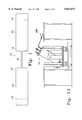
- FIG. 1is a simplified schematic view of a collagen mixing process of the present invention
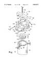
- FIG. 2is a perspective view, partially in section, of the preferred embodiment of the mixing portion of the apparatus of the present invention
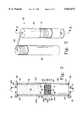
- FIG. 3is a sectional view of one of the mixing cylinders of FIG. 2 at section 3--3;
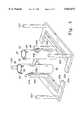
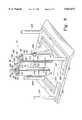
- FIG. 4is a perspective view of the shells of the mixing apparatus of the present received on moveable carts;
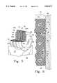
- FIG. 5is a perspective view, partially in section, of the piston configured for autoclaving
- FIG. 6is a partial sectional view of the piston and a portion of a mixing cylinder of the present invention.
- FIG. 7is an exploded view of the piston loading assembly of the present invention.
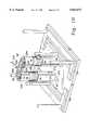
- FIG. 8is a perspective view of the apparatus of the present invention, partially in section, configured for pressure testing
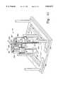
- FIG. 9is a perspective view of the apparatus of FIG. 8, partially in section, configured for centrate loading and sampling;
- FIG. 10is a perspective view of the apparatus of FIG. 8, partially in section, configured for centrate de-aeration;
- FIG. 11is a perspective view of the apparatus of FIG. 8, partially in section, configured for carrier fluid loading;
- FIG. 12is a perspective view of the apparatus of FIG. 8, partially in section, configured for centrate screening;
- FIG. 13is a perspective view of the apparatus of FIG. 8 configured for centrate de-lumping.
- FIG. 14is a schematic of the preferred embodiment of the control system for controlling the apparatus of the present invention.
- the present inventionprovides methods and apparatus for mixing a combined volume of constituents, such as a fluid and a particulate matter, with assurance that the entire combined volume or very nearly the entire combined volume of the constituents will be mixed together.
- the combined volumemay be a fixed volume, or the combined volume may change volume as the individual constituents are intermixed, such as by volume changes which occur during solubilization of one of the constituents into another of the constituents.
- the apparatusis particularly useful as a batch mixer for mixing highly viscous, high value products which must be maintained in a sterile environment, such as pharmaceuticals or other materials that may be used in humans and/or mammals.
- One such useis the redistributing of fibrils and fibril aggregates of collagen in a centrate 18 and for mixing the centrate 18 into a liquid carrier, and the invention will be primarily described with respect to this process. Additionally, the apparatus may be used to de-aggregate the larger fibril aggregates in the centrate. However, the invention is useful for distributing any particulate into a liquid, and should not be considered limited to the processing of collagen.
- the inventiongenerally includes a first variable volume member 14 a second variable volume member 14 which are interconnected by a fluid passage 16.
- a combined volume of the materialis loaded into the first variable volume member 12 to the level shown at line 13.
- the volume of the first variable volume member 12is then reduced to the volume shown at line 15, which forces nearly all of the material from the first variable volume 12 through the fluid passage 16 and into the second variable volume 14.
- the volume of the second variable volume 14is reduced to its minimum volume, as referenced at line 15', before the material is forced through the fluid passage 16.
- the second fluid volume 14is increased as the material moves therein through the fluid passage 16.
- the materialis passed through the fluid passage 16 multiple times which distributes the particulates into the liquid medium to a desired uniform concentration of particulate within the liquid, and may simultaneously reduce the mean particle size.
- the material being mixedis a collagen centrate 18
- the fibrils and fibril aggregatesare redistributed to a desired uniformity, and the larger aggregates are de-aggregated into smaller aggregates and individual fibrils as the centrate 18 is moved between the variable volumes 12, 14.
- the apparatus 10may also be used to mix the redistributed centrate 18 into a fluid carrier to form a final collagen product.
- the mixing apparatus 10 of the present inventionfor redistributing and if desired de-aggregating, collagen fibrils and fibril aggregates within a centrate 18 and then mixing the centrate 18 into a carrier fluid.
- the first variable volume member 12is configured as a first cylinder
- the second variable volume member 14is configured as a second cylinder 40
- the fluid passage 16is configured as a fluid interchange 60 interconnecting the cylinders 20, 40.
- the fluid interchange 60may include one or more fluid passages interconnecting the cylinders 20, 40, and only one such passage is shown in FIG. 2.
- the cylinders 20, 40are preferably identically configured to receive a discrete volume of collagen centrate 18 and pass the centrate 18 through the fluid interchange 60 to redistribute the collagen fibrils and fibril aggregates in the centrate 18 to a desired degree of uniformity, and to de-aggregate the fibril aggregates into smaller fibril aggregates and individual fibrils.
- the apparatus 10functions by forcing a combined volume of centrate 18 back and forth through the fluid interchange 60.
- the cross-sectional area of the cylindersis at least 20 times the cross sectional area of the fluid interchange 60.
- the centrate 18preferably flows through the fluid interchange 60 between the two cylinders 20, 40 at a rate of approximately one liter per second, and the fluid interchange 60 is sized to ensure turbulent movement of the centrate 18 through the fluid interchange 60.
- the cylinder 20includes a tubular shell 22 with opposed open lower and upper ends 24, 26, a lower cover plate 30 disposed over the lower open end 24 and an upper cover plate 28 disposed over the upper open end 26.
- the cover plates 28, 30are releasably attached to the ends 24 and 26, preferably with swinging bolt and wing nut combinations 25.
- An o-ring 27 or other seal memberis retained in a seal groove 29 in each end of the sleeve 22.
- the o-ring 27is preferably formed from silicone, and it forms a seal between the sleeve 22 and each of the cover plates 28, 30.
- a piston 34is located within the shell 22, and is actuatable therein between the cover plates 28, 30 as will be further described herein.
- the centrate 18 and any carrier fluidmust be mixed in a sterile environment. Additionally, all of the materials which the centrate 18 may contact must be non-cytotoxic, non-extractable materials.
- the shell 22 and cover plates 28, 30are fabricated from stainless steel, and the piston 34 is fabricated from polysulfone and stainless steel. Alternatively, the shell 22 may be fabricated from polysulfone.
- These individual components of the cylinders 20, 40, the components and fittings of the fluid interchange 60 and any other article which the centrate 18 or carrier fluid may contactmust also be sterilized. To provide a sterilized environment, the entire apparatus 10 of the present invention is configured to be disassembled for cleaning such as by autoclaving and then assembled and used in a class 100 clean room environment.
- the sleeve 22 of the cylinder 20is configured to connect to a cart 200
- the sleeve 22' of the cylinder 40is configured to connect to a cart 202 as shown in FIG. 4.
- the carts 200, 202, with the sleeves 22, 22' attached thereto,are sized to fit in an autoclaving chamber, and the carts 200, 202 allow the sleeves 22, 22' to be moved from the autoclaving chamber after sterilization without the sleeve 22, 22' being touched or otherwise contaminated.
- the carts and sleeve 22, 22', the pistons 34 (shown in FIG. 3), cover plates 28, 30 (shown in FIG. 3) and all seals, fittings and valves which may contact the centrate 18 of the carrier fluidare sterilized, preferably by autoclaving.
- Each of the carts 200, 202include a base 204 generally configured as a U-shaped member with wheels, a support 206 extending upwardly from the base 204 and a pair of steering rods 207.
- Each of the sleeves 22, 22'includes a mounting plate 208 on the outer surface thereof (best shown in FIG. 3) which is interconnected to the support 206 by a swivel rod 210.
- Each sleeve 22, 22'may be rotated 360° about the swivel rod 210, which allows the cylinder 20, 40 to be easily manipulated for placement of the sterilized componentry into or onto the cylinders 20, 40.
- the sleeves 22, 22'may be moved after autoclaving without being touched or otherwise contaminated.
- the mixing cylinders 20, 40are preferably configured to alternately force the centrate 18 therefrom and receive the centrate 18 therein.
- the volume within the cylinder 20 which receives the centrate 18may be varied by moving the piston 34 within the cylinder 20.
- the volume of the cylinder 20 which may receive the centrate 18is defined as the volume between the piston 34, the upper cover plate 28 and the inner wall of the shell 22. Therefore, as the piston 34 moves within the shell 22, the distance between the piston 34 and the cover plate 28, and thus the volume in the cylinder 20 which may receive the centrate 18, is reduced.
- the minimum volume of centrate 18is located in cylinder 20.
- the cylinder 20has a variable volume 32 for receiving the centrate 18.
- the maximum volume of the cylinder 20is at least as great as the maximum volume of centrate 18, and the minimum volume of the cylinder is approximately zero to provide minimum hold up of the collagen product.
- the piston 34is preferably a fully pneumatic/hydraulic piston 34, i.e., no mechanical linkage is provided to drive the piston 34 within the shell 22, the interface of the piston 34 and the shell 22 must have minimal friction. Additionally, the annular area, or gap 35, between the piston 34 and the shell 22 must be sealed, and the piston 34 must be configured to resist twisting, binding or cocking as it moves through the shell 22.
- the piston 34must be sized to closely match the inner diameter of the shell 22 to limit the size of any leak path between the piston 34 and the wall of the shell 22, but must be isolated from contact with the shell 22 to minimize friction and to avoid twisting, binding or cocking.
- the piston 34is preferably a multi-element member formed from a plurality of disks 33a-c, preferably manufactured from polysulfone, interconnected by an upper plate and stud assembly 39 and a lower plate 41.
- the stud of the upper plate and stud assembly 39extends through aligned apertures in the disks 33, and is received in the lower disk 41 to securely connect the disks 33a-c together to form the piston 34.
- a seal 43preferably configured from silicone, is provided between each disk adjacent the apertures to isolate the stud.
- the piston 34 thus formedincludes an outer cylindrical surface 62 bounded by an upper circular face 64 and a lower circular fact 66.
- the mean gap 35(best shown in FIG.
- An upper seal groove 68 and a lower seal groove 70are disposed in the outer cylindrical surface 62 of the piston 34 and extend circumferentially thereabout.
- the seal groove 68is disposed at the interface of the uppermost disk 33 and the middle disk 33b and includes a seal ring 72 therein
- the seal groove 70is disposed at the interface of the center disk 33b and the lowermost disk 33c and it includes a seal ring 73 therein.
- the seal rings 72, 73are configured to span the gap 35 between the piston 34 outer circumferential surface 62 and the inner wall of the shell 22, and to form a circumferential bearing surface on which the piston 34 slides along the inner wall of the shell 22 to maintain the piston 34 in a non-contacting relationship with the inner wall of the shell 22.
- the seal rings 72, 73also provide a means of centering the piston 34 within the shell 22, and thus help prevent twisting, binding or cocking of the piston 34 within the shell 22.
- the piston 34is specifically configured to be easily sterilized. Referring to FIG. 5, the piston 34 is shown partially assembled for autoclaving. In this configuration, the stud portion of the upper plate and stud assembly 39 is only partially received in the lower plate 41 of the piston 34, which allows the disks 33a-c of the piston 34 to be separated slightly during autoclaving. Further, a plurality of apertures 37 are provided through the outermost disks 33a, 33c around the circumference of the piston 34, and they terminate behind the seal grooves 68, 70 .
- the gaps between the disks 33a-c, and the porting affect of the apertures 37ensure that steam can contact all surfaces of the piston 35, including the back of the grooves 68, 70 and the back surfaces of the seals 72, 73 to ensure sterility. Further, the apertures 37 allow any condensation that forms adjacent the grooves 68, 70 during autoclaving to drain from the piston 34. Finally, during the autoclaving process, the piston 34 is held on its side on a fixture 45. This further ensures that any condensation that may form on the piston 34 during autoclaving drains from the piston 34 before use.
- Each seal ring 72, 73is preferably a double lip or double wiper seal, and includes a base 74 and opposed wipers 76, 78 projecting upwardly and outwardly from opposite sides of the base 74 to form a recess 82 therebetween.
- the base 74 and wipers 76, 78are preferably manufactured in one piece from ultra high molecular weight polyethylene.
- a spreader spring 80preferably configured from stainless steel, is located in the recess 82 between the wipers 76, 78.
- the spreader spring 80biases the inner wiper 76 into contact with the base of the groove 68, 70, and also biases the outer wiper 78 into contact with the inner surface of the shell 22.
- the positioning of the seal rings 72, 73 in the piston 34provides a buffer annulus 84 in the area bonded by the seal rings 72, 73 within the upper and lower grooves 68, 70, the wall of the shell 22 and the outer cylindrical surface 62 of the piston 34.
- This buffer annulus 84provides an intervening chamber between the conditions within the variable volume 32 and the conditions on the lower face 64 of the piston 34 to isolate the variable volume 32 from contamination.
- the inner wall of the shell 22is honed to a finish of 8 microinches, and then further electropolished to yield a 2 to 8 microinch electropolished surface.
- the alignment of the seal rings 72, 73 within the grooves 68, 70, in combination with the 2 to 8 microinch electropolish finish on the inner wall of the sleeve,helps to ensure that no materials will leak from the variable volume 32 and past the piston 34 and minimal particles of seal materials will be generated as the seals 72, 73 move over the inner wall of the shell. Generally, if any leaks occur past these seal rings 72, 73, the batch of centrate 18 being processed in the apparatus 10 must be destroyed.
- the seal rings 72, 73are received in the grooves 68, 70 such that the recess 82 in the seal ring 72 in the upper groove 68 is exposed to the variable volume 32, and the recess 82 in the seal ring 72 in the upper groove 68 is exposed to the volume within the cylinder 30 below the piston 34.
- This configurationhelps additionally load the outer wipers 78 of the seal rings 72 into engagement with the inner wall of the shell 22 as the piston 34 is moved under pressure.
- the multiple element configuration of the piston 34allows the use of semi-rigid seals 72, 73, because the seals 72, 73 are assemble into the piston 34 as the individual disks 33 that form the body of the piston 34 are assembled.
- the outer disks 33a and 33cpreferably include a square cut groove formed around the outer perimeter of one of the faces thereof, which when abutted against the adjacent center disk 33b forms the seal grooves 68, 70.
- the air pressure acting on the seal member 73'will additionally bias the wiper thereof into engagement with the inner wall of the shell 22', and the centrate loading on the upper surface of the piston 34' in the shell 22', and on the piston 34 in shell 22, will additionally bias the wipers 78, 78' of the seals 72, 72' against the inner wall of their respective shells 22, 22'.
- the cylinders 20, 40must be assembled, and the crossover 60 configured, to begin the loading, monitoring and redistributing of the centrate 18.
- the assembly of the apparatus 10is performed in a class 100 clean room.
- the apparatus 10should be configured for easy measurement of the centrate 18 and the carrier liquid. Therefore, in the preferred embodiment the carts 200, 202 with the sleeves 22, 22' thereon are pushed up a ramp 209 and onto a scale 211 maintained in the clean room. Once the carts 200, 202 are located on the scale 211, the cylinders 20, 40 may be assembled.
- the assembly of the covers 28, 30 and the various valves and fittingsis relatively straightforward so long as sterility is maintained. However, the loading of the piston 34 requires great care.
- the very small gap 35 between the piston 34 and the inner wall of the sleeve 22, on the order of 0.004 inches where the sleeve 22 has an inner diameter of approximately 8.25 inches,provides very little tolerance for aligning the piston 34 and the seals 72, 73, into the sleeve 22.
- the outer wiper 78 of the seal 72will tend to bind, twist or tear against the intersection of the inner wall of the shell 22 and the shell end 24 or 26, and the piston 34 can easily cock or bind as the piston 34 is lowered or pressed into the shell 22.
- the piston 34can contact the shell 22, and dent, scratch or otherwise damage either component, and the wiper 78 of the seal 72 can engage the end 24 of the shell 22 and further pressing of the piston 34 into the shell 22 may bend all or a portion of the wiper 78 back upon itself. In the best case, this will merely reduce the effectiveness of the seal 72. At worst, it will destroy the seal 72.
- the outer wiper 78 of the seal 72could be bent with a shim or feeler gage as the piston 34 is loaded into the shell 22, but these tools could nick or cut the seal 72 or damage the piston 34 and/or the sleeve 22 and thereby damage the sealing characteristics of the seal 72.
- the seals 72, 73must be easily retracted into their respective grooves 68, 70, but then allowed to actuate their outer wipers 78 into contact with the inner wall of the shell 22 once the piston 34 is received in the sleeve 22, and the piston 34 must enter the sleeve 22 with minimal misalignment.
- FIG. 7an exploded view of a load assembly 90 is shown for loading the piston 34 into the cylinder 20 without binding the seals 72, 73 as they are enter the shell 22.
- the shell 22is inverted on the carrier 200 such that the lower open end 24 of the shell 22 is upright.
- the piston 34is then received in a pre-sterilized load assembly 90.
- the load assembly 90is then attached to the upright lower end 24 of the shell 22 and the piston 34 is pressed therefrom into the shell 22.
- the load assembly 90depresses the seals 72, 73 into the seal grooves 68, 70 and maintains the seals 72, 73 in a depressed position as the seals 72, 73 enter the sleeve 22.
- the load assembly 90maintains the outer circumferential wall 62 of the piston 34 aligned with the inner wall of the shell 22. This helps prevent the piston 34 from contacting the inner wall of the shell 22 as the piston 34 enters the shell 22.
- the load assembly 90includes a pair of semicircular clamp halves 92, 94 which are interconnected about the piston 34.
- Each of the clamp halves 92, 94includes a semi-cylindrical inner portion 96, opposed connection flanges 98, 100 disposed approximately 180 apart on the opposed ends of the semi-cylindrical inner portion 96, and a rearwardly projecting lower flange 101 having an alignment tongue 103 (shown only on clamp halve 92) projecting downwardly therefrom and extending along the underside of the lower flange 101 in a semi-circular arc.
- each of the connection flanges 98, 100includes an alignment dowel hole 102, a clamping aperture 104 and a loading slot 106 therein (shown clearly in halve 92).
- the dowel hole 102, clamping aperture 104 and loading slot 106 on each flange 98, 100 on one of the clamp halves 92align with the dowel hole 102, clamping aperture 104 and loading slot 106 on the mating flange 98, 100 on the other of the semicircular clamp halves 94.
- the clamp halves 92, 94are placed around a piston 34, and a dowel 110 is placed in the dowel holes 102 of one of the clamp halves 92, 94.
- the clamp halves 92, 94are then brought into proximity to connect the dowel 110 into the dowel holes 102 in each of the flanges 98, 100, such as by impacting the clamp halves 92, 94 with a plastic mallet.
- the clamp halves 92, 94are interconnected by tee handled studs 112 inserted through each of the clamping apertures 104 and threaded into a nut 114 held on the back side of the aperture 104 in the opposite flange 96 or 98.
- the flange 98 of the clamp halve 92may be brought into contact with the flange 100 of the opposite clamp halve 94, and the flange 98 of the clamp halve 94 may be brought into contact with the flange 100 of the opposite clamp halve 92 by turning the tee handled studs 112 to bring the halves 92, 94 together.
- the semi-cylindrical portions 96 of the clamp halves 92, 94when loaded about the piston 34, depress the wipers 78 of the seals 72, 73 into the seal grooves 68, 70 of the piston 34 to a position such that the furthest outward extension of the wipers 78 is less than the gap 35 between the outer circumferential wall 62 of the piston and the inner wall of the sleeve 22 when the piston 34 is fully received in the sleeve 22.
- each clamp halve 92, 94is configured to form a semicircular extending rib that is received into the seal groove 29 in the end 24 of the sleeve 22 as the clamp halves are placed on the sleeve end 24.
- the piston 34is pressed out of the clamp halves 92, 94 and into the cylinder 20 or 40.
- the inner diameter between the semi-cylindrical inner portions 96is equal to, or slightly smaller than, the inner diameter of the sleeve 22. Therefore, as the piston 34 is pressed from the load assembly 90, the outer wipers 78 of the seals 72, 73 will be positioned radially inwardly of the inner wall of the sleeve 22 as the seal 72 or 73 exits the load assembly 90 and enters the sleeve 22.
- the load assembly 90preferably includes a integral press portion 116.
- this integral press portion 116includes a cross bar 118 extending between the clamp halves 92, 94 and over the center of the piston 34, a bearing plate 120 disposable against the piston 34, and a lead screw 122 extending through a threaded aperture 124 in the cross bar 118 and terminating on the bearing plate 120.
- the cross bar 118includes a downwardly projecting lip 119 at either end thereof, which includes an inwardly projecting tongue 121 thereon.
- the tongue 121may be slid into the loading slots 106 in each pair of opposed flanges 98, 100.
- the cross bar 118may be slid onto and off of the clamp halves 92, 94, but held rigidly in a longitudinal direction by the tongues 121 in the slots 106.
- the lead screw 122is turned to actuate the bearing plate 120 downwardly against the piston 34 to force the piston 34 into the sleeve 22.
- the lead screw 122engages the bearing plate 120 against the center of the piston 34. By loading the center of the piston 34, the piston 34 will enter the sleeve 22 with minimal cocking or binding.
- the interconnection of the cylinders 20, 40 to pass the centrate 18 between the two cylinders 20, 40is provided by the fluid interchange 60.
- the upper cover plate 28, 28' of each of the cylinders 20, 40includes a plurality of openings therethrough, to which multiple conduits may be attached to communicate between the variable volume 32 in the first cylinder 20 and the variable volume 32' in the second cylinder 40.
- the openingsinclude a first set of openings 50, 50', a second set of openings 52, 52' and a third set of openings 54, 54'.
- Each of the sets of openingsmay, if desired, be interlinked by a conduit to form all or a portion of the fluid interchange 60. Additionally, the openings may be used as ports to place fluids, such as carrier fluids, particulates or solids such as the collagen centrate 18, or vacuum or air supplies into the variable volumes 32, 32'.
- the upper cover plates 28, 28'also include an aperture 56 which is configured to receive a sensor 58 therein, preferably a proximity probe, which detects the presence of the piston 34 adjacent the top of the cylinder 20.
- each shell 22includes a level indicator 212 disposed longitudinally on the outer surface thereof.
- the indicator 212is preferably configured to provide an easily viewed indication of the level of the piston 34 within the cylinders 20, 40.
- One such indicatoris a flag type indicator, wherein a plurality of paddles 216 are disposed within a channel member 214.
- the paddles 216are supported on the side walls of the channel in low friction rotary connections, preferably by the receipt of the ends of a rod passing through the paddle 216 into the side walls of the channel 214.
- the channel 214is affixed to the outer wall of the cylinders 20, 40.
- a plurality of magnets 218is maintained are disposed within the piston 34, and the piston 34 and the channel 214 are assembled such that at least one of the magnets 218 (shown in FIG. 7) is maintained immediately behind the channel 214 within the cylinder 20 or 40.
- the piston 34moves in the cylinder 20 or 40, it sweeps a magnet along the back of the channel 214.
- Each of the paddles 216have a brightly colored side and a dark side.
- the magnet 218sweeps past each paddle 216, it flips the paddle 216 over about the rod to change the color of the paddle 216 as viewed through the indicator 212. Because a plurality of paddles 216 are disposed within the channel 214, the location on the channel 214 where the paddles 216 change from the dark color to the light color provides a visual display of the location of the piston 34.
- One indicator 212 having these propertiesis available from the MagTech Division of ISE of Texas, Inc. of Webster, Tex., under the designation "LG Series flipper/roller option.”
- LG Series flipper/roller optionOne skilled in the art will recognize that a number of different embodiments which include magnetically coupled indicators may be used to provide the piston level indicator.
- a plurality of sensorsmay be provided on the exterior of the cylinders 20, 40 to sense the passage of the magnets 218 therepast, and these sensors may be coupled to a processor or controller to record, or in conjunction with the air supplies control, the location of the piston 34 in the cylinders 20, 40.
- cylinders 20, 40are shown configured for pressure testing.
- a vacuum/air feed line 232is connected to the apertures 54, 54'
- a crossover line 234interconnects the apertures 52, 52'
- a pressure gauge 236 and quick connect fitting 238are located in each of the apertures 50, 50'.
- a valve 240is disposed in-line in the crossover line 234 to selectively isolate the two cylinders 20, 40 from each other.
- any leakage of the cylinders 20, 40, or of the piston seals 72,may be located, and the free movement of the pistons 34, 34' within the cylinders 20, 40 may be checked.
- each suction wand 242is connected into each of the apertures 50, 50', preferably through a sterile hose 244 placed in series with an automatic valve 247.
- Each suction wand 242includes a stem portion 246, which is preferably on the order of nine to twelve inches long, and a flared tip 248.
- the stem portion 246must be sufficiently long to enable an operator to hold the wand 242 in his or her hand and manipulate the flared tip 248 in a centrifuge bottle 249.
- the flared tip 248includes a flat portion 250 for scraping the base of the centrifuge bottle 249, and a rounded portion 252 to scrape the rounded wall of the centrifuge bottle 249.
- the cylinders 20, 40To load the centrate 18 into the cylinders 20, 40 through the suction wands 242, the cylinders 20, 40 must be operated at a vacuum. To provide this vacuum, an air/vacuum supply hose 254 is fitted to the bottom plate 30 of each of the cylinders 20, 40 (as shown in FIG. 3), and a vacuum is drawn into the cylinder below the pistons 34. Simultaneously, an identical vacuum is drawn through the vacuum/air feed line 232. This creates a vacuum in the variable volume 32, 32' of the cylinders 20, 40 above the pistons 34, 34'. The vacuum in the upper portion of the cylinders 20, 40 draws the centrate 18 through the wands 242.
- the automatic valves 247are operated by a foot switch, so that the operators may selectively open the valves 247 to suck centrate 18 into the wands 242.
- the configuration of the cylinders 20, 40 for de-aerating the centrate 18is shown.
- the cylinders 20, 40are configured to remove entrained air from the centrate 18.
- the vacuum/air feed line 232is disconnected from the apertures 54, 54' and connected across the apertures 50, 50'.
- a sightglass 256is placed in series with a manual sampling valve 258, and this series assembly is connected between manual valves 262, 264 located in the apertures 54, 54' to form a small crossover line 260.
- the small crossover line 260 and the crossover line 234together form the fluid interchange 60, and provide the total area through which the centrate 18 and the carrier will pass between the cylinders 20, 40 during mixing.
- a vacuumis pulled from the variable volumes 32, 32' of the cylinders 20, 40 containing the centrate 18, and from the underside of the pistons 34, 34'. Air entrained in the centrate 18 will froth out of the centrate 18, and be evacuated from the cylinders 20, 40 through the vacuum/air feed line 232. After the de-aeration step, but before mixing, the area below the pistons 34, 34' is vented, and the pistons 34, 34' move upwardly in the cylinders 20, 40 and into contact with the centrate 18. At this point the mixing of the centrate 18 to redistribute the fibril aggregates to create a homogenous concentration of collagen in the centrate 18, and to simultaneously reduce the maximum fibril aggregate size, may begin.
- the lower circular faces 64, 64' of the pistons 34, 34'are alternatively pressurized, which alternately drives the pressurized pistons 34, 34' upwardly in the sleeves 22, 22' to force the centrate 18 back and forth through the crossover line 234 and small crossover line 260.
- the crossover line 234has a seven-eighths inch inner diameter
- the small crossover line 260has a three-eighths inch inner diameter
- 17 liters of centrate 18will be sufficiently redistributed and have an acceptable maximum fibril aggregate size after 30 to 150 upward and downward cycles of each of the pistons 34, 34'.
- the centrate 18must be sampled to confirm that the operation of the apparatus 10 has properly redistributed the centrate 18 to create a uniform distribution of fibrils and fibril aggregates in the residual liquid medium, and to determine the proper amount of carrier liquid to add to the centrate 18 to form a final collagen product.
- one of the pistonsfor example piston 34 in cylinder 20, is actuated fully upwardly to force the centrate 18 into cylinder 40. Then, the crossover line 234 is closed, the piston 34' is moved upwardly in short incremental steps, and samples of the centrate 18 are removed through the sampling valve 258 at each incremental step.
- the operatorviews the indicator 216 on the side of the cylinder 40 to determine the position of the piston 34' within the cylinder 40.
- the samplesare then checked for collagen concentration, and for the uniformity of collagen concentration from sample to sample. If the samples have the desired concentration and uniformity, the centrate is then mixed with a carrier fluid. If the uniformity of the concentration is unacceptable, the centrate 18 is processed through another 50 cycles in the apparatus 10. If the concentration of the centrate 18 is too low, the centrate 18 is removed from the apparatus 10 and re-centrifuged.
- the sampled centrate 18may also be evaluated for particle size, if desired, with a Olympus Cue-2 Image analyzer available from Olympus of Japan using the technique described herein supra for diluting the centrate 18 and determining the size of the silhouettes of the fibrils and fibril aggregates.
- This devicewill determine the mean fibril size and the range of fibril sizes from the mean to a specified number of standard deviations in a collagen centrate. If the maximum fibril aggregate size is too large, or if the quantity of the larger fibril sizes would require too many screen changes, the centrate may be returned to the cylinders 20, 40 for mixing. Once the desired redistribution of the collagen in the centrate 18 has been accomplished with the apparatus, the centrate 18 may be de-aggregated in the apparatus indefinitely without affecting the homogeneous concentration of the centrate 18.
- the centrate 18must be mixed into a carrier liquid, preferably a carrier liquid which renders the centrate isotonic. Once the centrate 18 is mixed with a carrier fluid, it becomes diluted centrate.
- the apparatus 10is configured for the addition of the carrier liquid, commonly one or more buffer materials, into the homogenized centrate 18.
- the carrier loading apparatusis preferably a short piece of silicone tubing 266 attached at one end thereof to the sampling valve 258, and a tubular wand 268 is attached to the free end of the tubing 266.
- the sampling valve 258is opened and the tubular wand 268 is dipped into a sterile volume of carrier. Simultaneously, a vacuum is drawn through one or both of the air/vacuum supply hoses 232, 254 to draw the carrier into the cylinders 20, 40 through the tubular wand 268.
- the sampling valve 258is closed and the vacuum below the pistons 34, 341 is allowed to backfill with air. The combination of homogenized centrate 18 and carrier is then mixed by alternatively pressurizing the lower circular faces 64, 64' of the pistons 34, 34' to force the centrate 18 and carrier fluid back and forth through the fluid interchange 60.
- the diluted centrate 18 mixtureAfter mixing, the diluted centrate 18 mixture must be sampled, and if necessary, remixed or further diluted with carrier.
- the sampling valve 258again provides an easy source for sampling the mixture and for introducing more carrier to further dilute the diluted centrate, if necessary.
- the sampling valve 216is used in combination with the indicator 212 to sample the mixture at several locations within the fluid volume. By stepping the pistons 34 upwardly within their respective cylinders 20, 40 and noting the position of color change of the flippers 216 of the indicator 212, which color change corresponds to the position of the pistons 34 in the cylinders 20, 40, the operator may obtain samples from multiple locations within the volume of diluted centrate 18 and carrier.
- the mixing of the centrate 18 in the apparatus 10is normally sufficient to cause nearly all of the fibril aggregates having sizes greater than the desired aggregate size to separate into smaller aggregates or individual fibrils.
- the diluted centrateis screened. To perform the screening function, the entire volume of the diluted centrate is forced into cylinder 20, and the manual valve 258 is removed and replaced with a screen housing 270 placed in line with the sightglass 256 as shown in FIG. 12.
- the screen housing 270includes a screen therein, and the screen is selected so that the spaces in the screen mesh through which the diluted centrate is passed correspond to the size of the needle aperture through which the product that is ultimately produced from the batch of collagen must pass.
- the automatic valve 240 in the crossover line 234is closed and the diluted centrate is then forced from cylinder 20 to cylinder 40 through the small crossover line 260.
- the operatorcan determine if the screen in the screen housing 270 has become clogged. Whenever the screen becomes clogged, the transfer of the diluted centrate between the cylinders 20, 40 is stopped and the screen is replaced. Before replacing the screen, the valves 262, 264 are closed to prevent any unintended ejection of materials from the cylinders 20, 40.
- the entire volume of the diluted centrate in the second cylinder 40has a certifiable maximum fibril aggregate size.
- FIG. 13an apparatus configuration for further reducing the fibril aggregate size is shown.
- the diluted centrateis passed through a secondary de-lumping mixer 280 as it is pushed from cylinder 40 to cylinder 20.
- the secondary de-lumping mixer 280is a piston pump, which converts the mixture exiting from the cylinder 40 into two high velocity streams, and impinges these streams together in a 300 micron chamber at 2500 to 3000 psi which causes cavitation of the stream to cause further separation of the fibril aggregates.
- This mixer 280vigorously mechanically disrupts the centrate, and reduces the average fibril aggregate size by an amount sufficient to ensure that it will pass through a standard gauge needle, wherein the needle size varies with the intended use of the collagen.
- the de-lumped dilute centrateis then screened as would be any other diluted centrate.
- One apparatus useful as the mixer 280is available from Microfluidics Corporation, Newton Mass., under the designation HC-5000 Laboratory Homogenizer.
- the preferred control apparatus of the present inventionincludes a programmable controller 300 which is connected to a convertor 302 which is in turn connected to a touchview display panel 304.
- a microcomputer 306such as an IBM compatible 386 microcomputer, is connected to the process controller 300 to a state logic processor in the controller 300.
- the controller 300is configured to control the function of a mixing control unit 308 having multiple electric and pneumatic control switches therein.
- the control unit 306is connected to supplies of filtered shop air and vacuum.
- the control unit 308receives inputs from the controller 300 to control the function of the control switches which are configured to control the flow of air and the vacuum to the pistons 34, 34'.
- the touchview display 304provides visible indications of the operation of the apparatus 10, and it may also receive operator inputs to the controller 300.
- the controller 300reads inputs from the operator internal logic to control the mixing cycle.
- centrate 18is redistributed, de-aggregated, mixed with a carrier and then screened and de-lumped if necessary, it is ready for further processing.
- the cylinders 20, 40are specifically configured to be transportable, and the entire cylinder 20 or 40 having the collagen and carrier mixture therein may be simply wheeled into the next manufacturing area to be placed into syringes, implant materials or other configurations. This configuration allows the collagen to be transported to an additional processing station without compromising its sterility.
- the embodiments of the invention described hereinallow a combination of fluids and particulate matter, including collagen centrate 18 or diluted collagen centrate, to be intermixed to provide a homogenous concentration of collagen fibrils and fibril aggregates in the centrate 18 or carrier liquid, and, if necessary, reduce the maximum fibril aggregate size.
- the inventionis particularly suited for high viscosity fluid mixing, such as the redistributing of collagen in a centrate 18, and mixing that redistributed centrate 18 into a carrier liquid
- the inventionmay be used to mix many combinations of particulates and liquids, liquids and liquids, or even flowable particulates and particulates, and perform that mixing in a sterile environment.
- the inventionis of particular use where a high viscosity, high value product must be mixed and maintained in a sterile environment, because the quantity of hold up is minimal.
Landscapes
- Chemical & Material Sciences (AREA)
- Dispersion Chemistry (AREA)
- Chemical Kinetics & Catalysis (AREA)
- Apparatus Associated With Microorganisms And Enzymes (AREA)
- Prostheses (AREA)
- Accessories For Mixers (AREA)
- Mixers With Rotating Receptacles And Mixers With Vibration Mechanisms (AREA)
Abstract
Description
Claims (26)
Priority Applications (1)
| Application Number | Priority Date | Filing Date | Title |
|---|---|---|---|
| US08/555,270US5823671A (en) | 1994-05-10 | 1995-11-08 | Apparatus and method of mixing materials in a sterile environment |
Applications Claiming Priority (2)
| Application Number | Priority Date | Filing Date | Title |
|---|---|---|---|
| US24124494A | 1994-05-10 | 1994-05-10 | |
| US08/555,270US5823671A (en) | 1994-05-10 | 1995-11-08 | Apparatus and method of mixing materials in a sterile environment |
Related Parent Applications (1)
| Application Number | Title | Priority Date | Filing Date |
|---|---|---|---|
| US24124494AContinuation | 1994-05-10 | 1994-05-10 |
Publications (1)
| Publication Number | Publication Date |
|---|---|
| US5823671Atrue US5823671A (en) | 1998-10-20 |
Family
ID=22909870
Family Applications (1)
| Application Number | Title | Priority Date | Filing Date |
|---|---|---|---|
| US08/555,270Expired - LifetimeUS5823671A (en) | 1994-05-10 | 1995-11-08 | Apparatus and method of mixing materials in a sterile environment |
Country Status (7)
| Country | Link |
|---|---|
| US (1) | US5823671A (en) |
| EP (1) | EP0681863B1 (en) |
| JP (1) | JP2980825B2 (en) |
| CA (1) | CA2146090C (en) |
| DE (1) | DE69514862T2 (en) |
| ES (1) | ES2146679T3 (en) |
| MX (1) | MXPA95002006A (en) |
Cited By (66)
| Publication number | Priority date | Publication date | Assignee | Title |
|---|---|---|---|---|
| US20020101785A1 (en)* | 2001-01-26 | 2002-08-01 | Howmedica Osteonics Corp. | Cement mixing and dispensing device |
| US20030162708A1 (en)* | 2001-12-21 | 2003-08-28 | Jorgen Wolff | Haemostatic kit, a method of preparing a haemostatic agent and a method of promoting haemostatis |
| US20040120217A1 (en)* | 2002-12-23 | 2004-06-24 | Sentmanat Martin Lamar | Dual chamber orifice mixer and method of use |
| US20040125690A1 (en)* | 2002-12-30 | 2004-07-01 | Sentmanat Martin Lamar | Cascading orifice mixer |
| US20050052946A1 (en)* | 2003-09-08 | 2005-03-10 | Trivascular, Inc. | Fluid mixing apparatus and method |
| US20090148527A1 (en)* | 2007-12-07 | 2009-06-11 | Robinson Michael R | Intraocular formulation |
| US7654728B2 (en) | 1997-10-24 | 2010-02-02 | Revalesio Corporation | System and method for therapeutic application of dissolved oxygen |
| US7770814B2 (en) | 1997-10-24 | 2010-08-10 | Revalesio Corporation | System and method for irrigating with aerated water |
| US7806584B2 (en) | 1997-10-24 | 2010-10-05 | Revalesio Corporation | Diffuser/emulsifier |
| US7832920B2 (en) | 2006-10-25 | 2010-11-16 | Revalesio Corporation | Mixing device for creating an output mixture by mixing a first material and a second material |
| US7887698B2 (en) | 1997-10-24 | 2011-02-15 | Revalesio Corporation | Diffuser/emulsifier for aquaculture applications |
| US7923031B2 (en) | 2004-01-30 | 2011-04-12 | Ferrosan Medical Devices A/S | Haemostatic sprays and compositions |
| US7955288B2 (en) | 2002-12-11 | 2011-06-07 | Ferrosan Medical Devices A/S | Gelatine-based materials as swabs |
| US20110172180A1 (en)* | 2010-01-13 | 2011-07-14 | Allergan Industrie. Sas | Heat stable hyaluronic acid compositions for dermatological use |
| US20110224164A1 (en)* | 2010-03-12 | 2011-09-15 | Allergan Industrie, Sas | Fluid compositions for improving skin conditions |
| US8021684B2 (en) | 2004-07-09 | 2011-09-20 | Ferrosan Medical Devices A/S | Haemostatic composition comprising hyaluronic acid |
| US20110262231A1 (en)* | 2010-04-22 | 2011-10-27 | Micon | Pumpable Support with Cladding |
| US8338388B2 (en) | 2003-04-10 | 2012-12-25 | Allergan, Inc. | Cross-linking of low-molecular weight and high-molecular weight polysaccharides, preparation of injectable monophase hydrogels, polysaccharides and hydrogels obtained |
| US8338375B2 (en) | 2007-05-23 | 2012-12-25 | Allergan, Inc. | Packaged product |
| US8357795B2 (en) | 2008-08-04 | 2013-01-22 | Allergan, Inc. | Hyaluronic acid-based gels including lidocaine |
| US8394783B2 (en) | 2007-11-30 | 2013-03-12 | Allergan, Inc. | Polysaccharide gel formulation having multi-stage bioactive agent delivery |
| US8394782B2 (en) | 2007-11-30 | 2013-03-12 | Allergan, Inc. | Polysaccharide gel formulation having increased longevity |
| US8445546B2 (en) | 2006-10-25 | 2013-05-21 | Revalesio Corporation | Electrokinetically-altered fluids comprising charge-stabilized gas-containing nanostructures |
| US20130129554A1 (en)* | 2010-05-12 | 2013-05-23 | Audi Ag | Lubricant pump and control piston |
| US8591957B2 (en) | 2006-10-25 | 2013-11-26 | Revalesio Corporation | Methods of therapeutic treatment of eyes and other human tissues using an oxygen-enriched solution |
| US8609148B2 (en) | 2006-10-25 | 2013-12-17 | Revalesio Corporation | Methods of therapeutic treatment of eyes |
| US8617616B2 (en) | 2006-10-25 | 2013-12-31 | Revalesio Corporation | Methods of wound care and treatment |
| US8642831B2 (en) | 2008-02-29 | 2014-02-04 | Ferrosan Medical Devices A/S | Device for promotion of hemostasis and/or wound healing |
| US8691279B2 (en) | 2010-03-22 | 2014-04-08 | Allergan, Inc. | Polysaccharide and protein-polysaccharide cross-linked hydrogels for soft tissue augmentation |
| US8697044B2 (en) | 2007-10-09 | 2014-04-15 | Allergan, Inc. | Crossed-linked hyaluronic acid and collagen and uses thereof |
| US8697057B2 (en) | 2010-08-19 | 2014-04-15 | Allergan, Inc. | Compositions and soft tissue replacement methods |
| US8784897B2 (en) | 2006-10-25 | 2014-07-22 | Revalesio Corporation | Methods of therapeutic treatment of eyes |
| US8784898B2 (en) | 2006-10-25 | 2014-07-22 | Revalesio Corporation | Methods of wound care and treatment |
| US8815292B2 (en) | 2009-04-27 | 2014-08-26 | Revalesio Corporation | Compositions and methods for treating insulin resistance and diabetes mellitus |
| US8883139B2 (en) | 2010-08-19 | 2014-11-11 | Allergan Inc. | Compositions and soft tissue replacement methods |
| US8889123B2 (en) | 2010-08-19 | 2014-11-18 | Allergan, Inc. | Compositions and soft tissue replacement methods |
| US8980325B2 (en) | 2008-05-01 | 2015-03-17 | Revalesio Corporation | Compositions and methods for treating digestive disorders |
| US9005605B2 (en) | 2010-08-19 | 2015-04-14 | Allergan, Inc. | Compositions and soft tissue replacement methods |
| US9114188B2 (en) | 2010-01-13 | 2015-08-25 | Allergan, Industrie, S.A.S. | Stable hydrogel compositions including additives |
| US9149422B2 (en) | 2011-06-03 | 2015-10-06 | Allergan, Inc. | Dermal filler compositions including antioxidants |
| US9198929B2 (en) | 2010-05-07 | 2015-12-01 | Revalesio Corporation | Compositions and methods for enhancing physiological performance and recovery time |
| US9228027B2 (en) | 2008-09-02 | 2016-01-05 | Allergan Holdings France S.A.S. | Threads of Hyaluronic acid and/or derivatives thereof, methods of making thereof and uses thereof |
| US9265761B2 (en) | 2007-11-16 | 2016-02-23 | Allergan, Inc. | Compositions and methods for treating purpura |
| US9265858B2 (en) | 2012-06-12 | 2016-02-23 | Ferrosan Medical Devices A/S | Dry haemostatic composition |
| US9393263B2 (en) | 2011-06-03 | 2016-07-19 | Allergan, Inc. | Dermal filler compositions including antioxidants |
| US9408797B2 (en) | 2011-06-03 | 2016-08-09 | Allergan, Inc. | Dermal filler compositions for fine line treatment |
| US9492404B2 (en) | 2010-08-12 | 2016-11-15 | Revalesio Corporation | Compositions and methods for treatment of taupathy |
| US9523090B2 (en) | 2007-10-25 | 2016-12-20 | Revalesio Corporation | Compositions and methods for treating inflammation |
| US9724078B2 (en) | 2013-06-21 | 2017-08-08 | Ferrosan Medical Devices A/S | Vacuum expanded dry composition and syringe for retaining same |
| US9745567B2 (en) | 2008-04-28 | 2017-08-29 | Revalesio Corporation | Compositions and methods for treating multiple sclerosis |
| US9795711B2 (en) | 2011-09-06 | 2017-10-24 | Allergan, Inc. | Hyaluronic acid-collagen matrices for dermal filling and volumizing applications |
| US10111980B2 (en) | 2013-12-11 | 2018-10-30 | Ferrosan Medical Devices A/S | Dry composition comprising an extrusion enhancer |
| US10111981B2 (en) | 2013-03-04 | 2018-10-30 | Dermelle, Llc | Injectable in situ polymerizable collagen composition |
| US10125359B2 (en) | 2007-10-25 | 2018-11-13 | Revalesio Corporation | Compositions and methods for treating inflammation |
| US10653837B2 (en) | 2014-12-24 | 2020-05-19 | Ferrosan Medical Devices A/S | Syringe for retaining and mixing first and second substances |
| US10722444B2 (en) | 2014-09-30 | 2020-07-28 | Allergan Industrie, Sas | Stable hydrogel compositions including additives |
| US10918796B2 (en) | 2015-07-03 | 2021-02-16 | Ferrosan Medical Devices A/S | Syringe for mixing two components and for retaining a vacuum in a storage condition |
| US11046818B2 (en) | 2014-10-13 | 2021-06-29 | Ferrosan Medical Devices A/S | Dry composition for use in haemostasis and wound healing |
| US11083684B2 (en) | 2011-06-03 | 2021-08-10 | Allergan Industrie, Sas | Dermal filler compositions |
| US11109849B2 (en) | 2012-03-06 | 2021-09-07 | Ferrosan Medical Devices A/S | Pressurized container containing haemostatic paste |
| US11260015B2 (en) | 2015-02-09 | 2022-03-01 | Allergan Industrie, Sas | Compositions and methods for improving skin appearance |
| US11801324B2 (en) | 2018-05-09 | 2023-10-31 | Ferrosan Medical Devices A/S | Method for preparing a haemostatic composition |
| US11844878B2 (en) | 2011-09-06 | 2023-12-19 | Allergan, Inc. | Crosslinked hyaluronic acid-collagen gels for improving tissue graft viability and soft tissue augmentation |
| US11980699B2 (en) | 2021-09-01 | 2024-05-14 | Shanghai Qisheng Biological Preparation Co., Ltd. | Cartilage regeneration using injectable, in situ polymerizable collagen compositions containing chondrocytes or stem cells |
| US12304974B2 (en) | 2021-12-28 | 2025-05-20 | Shanghai Qisheng Biological Preparation Co., Ltd. | Hyaluronic acid-collagen copolymer compositions and medical applications thereof |
| US12324868B2 (en) | 2015-02-13 | 2025-06-10 | Allergan Industrie, Sas | Implants for sculpting, augmenting or correcting facial features such as the chin |
Families Citing this family (3)
| Publication number | Priority date | Publication date | Assignee | Title |
|---|---|---|---|---|
| FR2777284B1 (en)* | 1998-04-10 | 2000-05-26 | Hamza Mansour | PROCESS FOR THE STERILIZATION OF A NATIVE COLLAGEN IN A LIQUID MEDIUM, A STERILE NATIVE COLLAGEN OBTAINED, COMPOSITIONS CONTAINING THE SAME AND APPLICATIONS |
| DE102008058034B4 (en)* | 2008-11-18 | 2014-05-15 | Imp Pape Gmbh & Co. Kg | Use of a syringe as a storage container for ready-to-use pharmaceutical preparations and syringe set |
| CN116084915B (en)* | 2022-12-19 | 2024-10-18 | 四川大学 | A simulation device for in-situ film formation and quality preservation of core sampling of combustible ice while drilling |
Citations (40)
| Publication number | Priority date | Publication date | Assignee | Title |
|---|---|---|---|---|
| DE35486C (en)* | E. SPANDAU in Magdeburg, Hartstrafse 7 II | Average liquid sampler | ||
| GB1052971A (en)* | 1962-10-25 | |||
| US1458067A (en)* | 1921-10-13 | 1923-06-05 | Michael S Linton | Piston-ring tool |
| GB229277A (en)* | 1924-02-11 | 1925-08-27 | Georg Schwager | |
| US2477598A (en)* | 1948-02-16 | 1949-08-02 | George M Hain | Microworker for lubricating greases |
| US2716272A (en)* | 1951-05-02 | 1955-08-30 | Muskegon Piston Ring Co Inc | Piston and piston ring installing tool |
| US2859017A (en)* | 1956-10-18 | 1958-11-04 | Semco Res Inc | Apparatus for air-free mixing of fluid materials |
| US3010705A (en)* | 1960-09-26 | 1961-11-28 | Brown Ethan Allan | Emulsifiers |
| US3390580A (en)* | 1966-01-24 | 1968-07-02 | L.B. Taylor | Sample systems |
| US3700215A (en)* | 1970-10-21 | 1972-10-24 | Hardman Inc | Mixing and dispensing device |
| FR2152452A1 (en)* | 1971-09-10 | 1973-04-27 | Merlin Gerin | Resin mixer dispenser unit - using twin adjustable throw pistons for a controlled volume discharge |
| FR2158118A2 (en)* | 1971-11-03 | 1973-06-15 | Merlin Gerin | Resin mixer dispenser - with fully emptying spherical diaphragm pump chambers to reduce stagnation and membrane wear |
| DE2216340A1 (en)* | 1972-04-05 | 1973-11-08 | Westinghouse Bremsen Apparate | METHOD AND DEVICE FOR INSERTING PISTONS WITH PISTON RINGS IN CYLINDERS |
| US3793718A (en)* | 1971-11-08 | 1974-02-26 | Mitsui Shipbuilding Eng | Apparatus for removing or inserting a piston in reciprocating engines |
| US3949073A (en)* | 1974-11-18 | 1976-04-06 | The Board Of Trustees Of Leland Stanford Junior University | Process for augmenting connective mammalian tissue with in situ polymerizable native collagen solution |
| US3952393A (en)* | 1974-01-17 | 1976-04-27 | International Standard Electric Corporation | Machine and method for assembling pistons into engines |
| US4106779A (en)* | 1975-03-03 | 1978-08-15 | Nl Hycalog | Automatic sequential dual action sealing system |
| GB2048090A (en)* | 1979-02-09 | 1980-12-10 | Colombo C Cereghini G Cristofo | Mixing Liquids |
| US4240644A (en)* | 1977-04-27 | 1980-12-23 | Gemini Seals, Inc. | Piston seal |
| JPS5676349A (en)* | 1979-11-16 | 1981-06-23 | Hitachi Seiki Co Ltd | Automatic assembling device for piston |
| JPS5676350A (en)* | 1979-11-20 | 1981-06-23 | Hitachi Seiki Co Ltd | Automatic assembling device for piston |
| US4347002A (en)* | 1979-01-16 | 1982-08-31 | Born Raisa I | Method and apparatus for the preparation of drilling mud |
| WO1982004127A1 (en)* | 1981-05-15 | 1982-11-25 | Olenfalk Lars | Apparatus for sampling of liquid |
| EP0092975A1 (en)* | 1982-04-27 | 1983-11-02 | The British Petroleum Company p.l.c. | Sample receiving and mixing device |
| JPS59115129A (en)* | 1982-12-22 | 1984-07-03 | Honda Motor Co Ltd | How to assemble the piston |
| US4548509A (en)* | 1984-10-05 | 1985-10-22 | Clif Mock Company | Mixing disc |
| US4626700A (en)* | 1984-07-05 | 1986-12-02 | Nippon Air Brake Co., Ltd. | Hydraulic reservoir with fluid level detector |
| US4651623A (en)* | 1984-12-07 | 1987-03-24 | American Standard Inc. | Work cylinder having a piston member with an integral cushioning arrangement |
| JPS62228116A (en)* | 1986-03-28 | 1987-10-07 | Tokyo Tatsuno Co Ltd | How to assemble the piston in a piston type flowmeter |
| US4754984A (en)* | 1987-01-02 | 1988-07-05 | The United States Of America As Represented By The Secretary Of The Navy | Dual-seal-ring shaft seal |
| US4805758A (en)* | 1987-07-08 | 1989-02-21 | Van Dam Machine Corporation | Crossed turret cup feeder |
| US4846780A (en)* | 1988-08-10 | 1989-07-11 | Exxon Production Research Company | Centrifuge processor and liquid level control system |
| EP0324934A1 (en)* | 1987-12-10 | 1989-07-26 | Colgate-Palmolive Company | Apparatus for making a post-foaming gel |
| US4881326A (en)* | 1987-02-13 | 1989-11-21 | Leybold Aktiengesellschaft | Sterilizing device for a freeze-drying apparatus |
| US4883150A (en)* | 1987-03-20 | 1989-11-28 | Tokico Ltd. | Hydraulic shock absorber with piston rod position detecting means |
| US5002463A (en)* | 1988-07-29 | 1991-03-26 | Innovac Technology Inc. | Apparatus and method for flow control |
| US5143382A (en)* | 1991-03-04 | 1992-09-01 | W. S. Shamban & Company | Pressure relieving slipper seal system |
| WO1993012413A1 (en)* | 1991-12-19 | 1993-06-24 | Ultrakust Electronic Gmbh | Process and device for taking representative milk samples |
| US5328441A (en)* | 1991-12-04 | 1994-07-12 | Carr Engineering Associates, Inc. | Imperforate bowl centrifugal separator with solids gate |
| US5356367A (en)* | 1991-12-04 | 1994-10-18 | Carr Engineering Associates, Inc. | Centrifugal separator with flexibly suspended restrainable bowl |
- 1995
- 1995-03-31CACA002146090Apatent/CA2146090C/ennot_activeExpired - Fee Related
- 1995-04-28MXMXPA95002006Apatent/MXPA95002006A/enunknown
- 1995-05-09DEDE69514862Tpatent/DE69514862T2/ennot_activeExpired - Lifetime
- 1995-05-09JPJP7110991Apatent/JP2980825B2/ennot_activeExpired - Fee Related
- 1995-05-09EPEP95107000Apatent/EP0681863B1/ennot_activeExpired - Lifetime
- 1995-05-09ESES95107000Tpatent/ES2146679T3/ennot_activeExpired - Lifetime
- 1995-11-08USUS08/555,270patent/US5823671A/ennot_activeExpired - Lifetime
Patent Citations (41)
| Publication number | Priority date | Publication date | Assignee | Title |
|---|---|---|---|---|
| DE35486C (en)* | E. SPANDAU in Magdeburg, Hartstrafse 7 II | Average liquid sampler | ||
| US1458067A (en)* | 1921-10-13 | 1923-06-05 | Michael S Linton | Piston-ring tool |
| GB229277A (en)* | 1924-02-11 | 1925-08-27 | Georg Schwager | |
| US2477598A (en)* | 1948-02-16 | 1949-08-02 | George M Hain | Microworker for lubricating greases |
| US2716272A (en)* | 1951-05-02 | 1955-08-30 | Muskegon Piston Ring Co Inc | Piston and piston ring installing tool |
| US2859017A (en)* | 1956-10-18 | 1958-11-04 | Semco Res Inc | Apparatus for air-free mixing of fluid materials |
| US3010705A (en)* | 1960-09-26 | 1961-11-28 | Brown Ethan Allan | Emulsifiers |
| GB1052971A (en)* | 1962-10-25 | |||
| US3390580A (en)* | 1966-01-24 | 1968-07-02 | L.B. Taylor | Sample systems |
| US3700215A (en)* | 1970-10-21 | 1972-10-24 | Hardman Inc | Mixing and dispensing device |
| FR2152452A1 (en)* | 1971-09-10 | 1973-04-27 | Merlin Gerin | Resin mixer dispenser unit - using twin adjustable throw pistons for a controlled volume discharge |
| FR2158118A2 (en)* | 1971-11-03 | 1973-06-15 | Merlin Gerin | Resin mixer dispenser - with fully emptying spherical diaphragm pump chambers to reduce stagnation and membrane wear |
| US3793718A (en)* | 1971-11-08 | 1974-02-26 | Mitsui Shipbuilding Eng | Apparatus for removing or inserting a piston in reciprocating engines |
| DE2216340A1 (en)* | 1972-04-05 | 1973-11-08 | Westinghouse Bremsen Apparate | METHOD AND DEVICE FOR INSERTING PISTONS WITH PISTON RINGS IN CYLINDERS |
| US3952393A (en)* | 1974-01-17 | 1976-04-27 | International Standard Electric Corporation | Machine and method for assembling pistons into engines |
| US3949073A (en)* | 1974-11-18 | 1976-04-06 | The Board Of Trustees Of Leland Stanford Junior University | Process for augmenting connective mammalian tissue with in situ polymerizable native collagen solution |
| US4106779A (en)* | 1975-03-03 | 1978-08-15 | Nl Hycalog | Automatic sequential dual action sealing system |
| US4240644A (en)* | 1977-04-27 | 1980-12-23 | Gemini Seals, Inc. | Piston seal |
| US4347002A (en)* | 1979-01-16 | 1982-08-31 | Born Raisa I | Method and apparatus for the preparation of drilling mud |
| GB2048090A (en)* | 1979-02-09 | 1980-12-10 | Colombo C Cereghini G Cristofo | Mixing Liquids |
| JPS5676349A (en)* | 1979-11-16 | 1981-06-23 | Hitachi Seiki Co Ltd | Automatic assembling device for piston |
| JPS5676350A (en)* | 1979-11-20 | 1981-06-23 | Hitachi Seiki Co Ltd | Automatic assembling device for piston |
| WO1982004127A1 (en)* | 1981-05-15 | 1982-11-25 | Olenfalk Lars | Apparatus for sampling of liquid |
| EP0092975A1 (en)* | 1982-04-27 | 1983-11-02 | The British Petroleum Company p.l.c. | Sample receiving and mixing device |
| JPS59115129A (en)* | 1982-12-22 | 1984-07-03 | Honda Motor Co Ltd | How to assemble the piston |
| US4626700A (en)* | 1984-07-05 | 1986-12-02 | Nippon Air Brake Co., Ltd. | Hydraulic reservoir with fluid level detector |
| US4548509A (en)* | 1984-10-05 | 1985-10-22 | Clif Mock Company | Mixing disc |
| US4651623A (en)* | 1984-12-07 | 1987-03-24 | American Standard Inc. | Work cylinder having a piston member with an integral cushioning arrangement |
| JPS62228116A (en)* | 1986-03-28 | 1987-10-07 | Tokyo Tatsuno Co Ltd | How to assemble the piston in a piston type flowmeter |
| US4754984A (en)* | 1987-01-02 | 1988-07-05 | The United States Of America As Represented By The Secretary Of The Navy | Dual-seal-ring shaft seal |
| US4881326A (en)* | 1987-02-13 | 1989-11-21 | Leybold Aktiengesellschaft | Sterilizing device for a freeze-drying apparatus |
| US4883150A (en)* | 1987-03-20 | 1989-11-28 | Tokico Ltd. | Hydraulic shock absorber with piston rod position detecting means |
| US4805758A (en)* | 1987-07-08 | 1989-02-21 | Van Dam Machine Corporation | Crossed turret cup feeder |
| EP0324934A1 (en)* | 1987-12-10 | 1989-07-26 | Colgate-Palmolive Company | Apparatus for making a post-foaming gel |
| US5002463A (en)* | 1988-07-29 | 1991-03-26 | Innovac Technology Inc. | Apparatus and method for flow control |
| US4846780A (en)* | 1988-08-10 | 1989-07-11 | Exxon Production Research Company | Centrifuge processor and liquid level control system |
| US5143382A (en)* | 1991-03-04 | 1992-09-01 | W. S. Shamban & Company | Pressure relieving slipper seal system |
| US5328441A (en)* | 1991-12-04 | 1994-07-12 | Carr Engineering Associates, Inc. | Imperforate bowl centrifugal separator with solids gate |
| US5356367A (en)* | 1991-12-04 | 1994-10-18 | Carr Engineering Associates, Inc. | Centrifugal separator with flexibly suspended restrainable bowl |
| US5425698A (en)* | 1991-12-04 | 1995-06-20 | Carr Engineering Associates, Inc. | Centrifugal separator with flexibly suspended restrainable bowl |
| WO1993012413A1 (en)* | 1991-12-19 | 1993-06-24 | Ultrakust Electronic Gmbh | Process and device for taking representative milk samples |
Non-Patent Citations (6)
| Title |
|---|
| Patent Abstracts of JP, vol. 005, No. 143 (M 087), Sep. 9, 1981 (Abstract of JP 56 076350), a copy of which is also enclosed.* |
| Patent Abstracts of JP, vol. 005, No. 143 (M-087), Sep. 9, 1981 (Abstract of JP 56-076350), a copy of which is also enclosed. |
| Patent Abstracts of JP, vol. 012, No. 095 (P 681), Mar. 29, 1988 (Abstract of JP 62 228116), a copy of which is also enclosed.* |
| Patent Abstracts of JP, vol. 012, No. 095 (P-681), Mar. 29, 1988 (Abstract of JP 62-228116), a copy of which is also enclosed. |
| Patente Abstracts of JP, vol. 008, No. 234 (M 334), Oct. 26, 1984 (Abstract of JP 59 115129), a copy of which is also enclosed.* |
| Patente Abstracts of JP, vol. 008, No. 234 (M-334), Oct. 26, 1984 (Abstract of JP 59-115129), a copy of which is also enclosed. |
Cited By (142)
| Publication number | Priority date | Publication date | Assignee | Title |
|---|---|---|---|---|
| US7770814B2 (en) | 1997-10-24 | 2010-08-10 | Revalesio Corporation | System and method for irrigating with aerated water |
| US8349191B2 (en) | 1997-10-24 | 2013-01-08 | Revalesio Corporation | Diffuser/emulsifier for aquaculture applications |
| US7887698B2 (en) | 1997-10-24 | 2011-02-15 | Revalesio Corporation | Diffuser/emulsifier for aquaculture applications |
| US9034195B2 (en) | 1997-10-24 | 2015-05-19 | Revalesio Corporation | Diffuser/emulsifier for aquaculture applications |
| US7806584B2 (en) | 1997-10-24 | 2010-10-05 | Revalesio Corporation | Diffuser/emulsifier |
| US7654728B2 (en) | 1997-10-24 | 2010-02-02 | Revalesio Corporation | System and method for therapeutic application of dissolved oxygen |
| US6592251B2 (en)* | 2001-01-26 | 2003-07-15 | Howmedica Osteonics Corp. | Cement mixing and dispensing device |
| US20020101785A1 (en)* | 2001-01-26 | 2002-08-01 | Howmedica Osteonics Corp. | Cement mixing and dispensing device |
| US20030162708A1 (en)* | 2001-12-21 | 2003-08-28 | Jorgen Wolff | Haemostatic kit, a method of preparing a haemostatic agent and a method of promoting haemostatis |
| US8283320B2 (en) | 2001-12-21 | 2012-10-09 | Ferrosan Medical Devices A/S | Haemostatic kit, a method of preparing a haemostatic agent and a method of promoting haemostasis |
| US7923431B2 (en)* | 2001-12-21 | 2011-04-12 | Ferrosan Medical Devices A/S | Haemostatic kit, a method of preparing a haemostatic agent and a method of promoting haemostatis |
| US7955288B2 (en) | 2002-12-11 | 2011-06-07 | Ferrosan Medical Devices A/S | Gelatine-based materials as swabs |
| US6799884B2 (en) | 2002-12-23 | 2004-10-05 | The Goodyear Tire And Rubber Company | Dual chamber orifice mixer and method of use |
| US20040120217A1 (en)* | 2002-12-23 | 2004-06-24 | Sentmanat Martin Lamar | Dual chamber orifice mixer and method of use |
| US7033067B2 (en) | 2002-12-30 | 2006-04-25 | The Goodyear Tire & Rubber Company | Cascading orifice mixer |
| US20040125690A1 (en)* | 2002-12-30 | 2004-07-01 | Sentmanat Martin Lamar | Cascading orifice mixer |
| US9062130B2 (en) | 2003-04-10 | 2015-06-23 | Allergan Industrie Sas | Cross-linking of low-molecular weight and high-molecular weight polysaccharides, preparation of injectable monophase hydrogels, polysaccharides and hydrogels obtained |
| US10653716B2 (en) | 2003-04-10 | 2020-05-19 | Allergan Industrie, Sas | Injectable monophase hydrogels |
| US8563532B2 (en) | 2003-04-10 | 2013-10-22 | Allergan Industrie Sas | Cross-linking of low-molecular weight and high-molecular weight polysaccharides, preparation of injectable monophase hydrogels, polysaccharides and hydrogels obtained |
| US11045490B2 (en) | 2003-04-10 | 2021-06-29 | Allergan Industrie, Sas | Injectable monophase hydrogels |
| US10080767B2 (en) | 2003-04-10 | 2018-09-25 | Allergan Industrie Sas | Injectable monophase hydrogels |
| US8338388B2 (en) | 2003-04-10 | 2012-12-25 | Allergan, Inc. | Cross-linking of low-molecular weight and high-molecular weight polysaccharides, preparation of injectable monophase hydrogels, polysaccharides and hydrogels obtained |
| US20050052946A1 (en)* | 2003-09-08 | 2005-03-10 | Trivascular, Inc. | Fluid mixing apparatus and method |
| US7178978B2 (en)* | 2003-09-08 | 2007-02-20 | Boston Scientific Santa Rosa Corp., | Fluid mixing apparatus and method |
| US7923031B2 (en) | 2004-01-30 | 2011-04-12 | Ferrosan Medical Devices A/S | Haemostatic sprays and compositions |
| US8021684B2 (en) | 2004-07-09 | 2011-09-20 | Ferrosan Medical Devices A/S | Haemostatic composition comprising hyaluronic acid |
| US8609148B2 (en) | 2006-10-25 | 2013-12-17 | Revalesio Corporation | Methods of therapeutic treatment of eyes |
| US8449172B2 (en) | 2006-10-25 | 2013-05-28 | Revalesio Corporation | Mixing device for creating an output mixture by mixing a first material and a second material |
| US9004743B2 (en) | 2006-10-25 | 2015-04-14 | Revalesio Corporation | Mixing device for creating an output mixture by mixing a first material and a second material |
| US8784898B2 (en) | 2006-10-25 | 2014-07-22 | Revalesio Corporation | Methods of wound care and treatment |
| US8784897B2 (en) | 2006-10-25 | 2014-07-22 | Revalesio Corporation | Methods of therapeutic treatment of eyes |
| US8410182B2 (en) | 2006-10-25 | 2013-04-02 | Revalesio Corporation | Mixing device |
| US8445546B2 (en) | 2006-10-25 | 2013-05-21 | Revalesio Corporation | Electrokinetically-altered fluids comprising charge-stabilized gas-containing nanostructures |
| US9511333B2 (en) | 2006-10-25 | 2016-12-06 | Revalesio Corporation | Ionic aqueous solutions comprising charge-stabilized oxygen-containing nanobubbles |
| US9512398B2 (en) | 2006-10-25 | 2016-12-06 | Revalesio Corporation | Ionic aqueous solutions comprising charge-stabilized oxygen-containing nanobubbles |
| US8617616B2 (en) | 2006-10-25 | 2013-12-31 | Revalesio Corporation | Methods of wound care and treatment |
| US8470893B2 (en) | 2006-10-25 | 2013-06-25 | Revalesio Corporation | Electrokinetically-altered fluids comprising charge-stabilized gas-containing nanostructures |
| US7832920B2 (en) | 2006-10-25 | 2010-11-16 | Revalesio Corporation | Mixing device for creating an output mixture by mixing a first material and a second material |
| US9402803B2 (en) | 2006-10-25 | 2016-08-02 | Revalesio Corporation | Methods of wound care and treatment |
| US7919534B2 (en) | 2006-10-25 | 2011-04-05 | Revalesio Corporation | Mixing device |
| US8591957B2 (en) | 2006-10-25 | 2013-11-26 | Revalesio Corporation | Methods of therapeutic treatment of eyes and other human tissues using an oxygen-enriched solution |
| US8597689B2 (en) | 2006-10-25 | 2013-12-03 | Revalesio Corporation | Methods of wound care and treatment |
| US8962700B2 (en) | 2006-10-25 | 2015-02-24 | Revalesio Corporation | Electrokinetically-altered fluids comprising charge-stabilized gas-containing nanostructures |
| US8338375B2 (en) | 2007-05-23 | 2012-12-25 | Allergan, Inc. | Packaged product |
| US8697044B2 (en) | 2007-10-09 | 2014-04-15 | Allergan, Inc. | Crossed-linked hyaluronic acid and collagen and uses thereof |
| US8703118B2 (en) | 2007-10-09 | 2014-04-22 | Allergan, Inc. | Crossed-linked hyaluronic acid and collagen and uses thereof |
| US9523090B2 (en) | 2007-10-25 | 2016-12-20 | Revalesio Corporation | Compositions and methods for treating inflammation |
| US10125359B2 (en) | 2007-10-25 | 2018-11-13 | Revalesio Corporation | Compositions and methods for treating inflammation |
| US9265761B2 (en) | 2007-11-16 | 2016-02-23 | Allergan, Inc. | Compositions and methods for treating purpura |
| US8394782B2 (en) | 2007-11-30 | 2013-03-12 | Allergan, Inc. | Polysaccharide gel formulation having increased longevity |
| US8394784B2 (en) | 2007-11-30 | 2013-03-12 | Allergan, Inc. | Polysaccharide gel formulation having multi-stage bioactive agent delivery |
| US8394783B2 (en) | 2007-11-30 | 2013-03-12 | Allergan, Inc. | Polysaccharide gel formulation having multi-stage bioactive agent delivery |
| US8853184B2 (en) | 2007-11-30 | 2014-10-07 | Allergan, Inc. | Polysaccharide gel formulation having increased longevity |
| US8513216B2 (en) | 2007-11-30 | 2013-08-20 | Allergan, Inc. | Polysaccharide gel formulation having increased longevity |
| US20090148527A1 (en)* | 2007-12-07 | 2009-06-11 | Robinson Michael R | Intraocular formulation |
| US8642831B2 (en) | 2008-02-29 | 2014-02-04 | Ferrosan Medical Devices A/S | Device for promotion of hemostasis and/or wound healing |
| US9533069B2 (en) | 2008-02-29 | 2017-01-03 | Ferrosan Medical Devices A/S | Device for promotion of hemostasis and/or wound healing |
| US9745567B2 (en) | 2008-04-28 | 2017-08-29 | Revalesio Corporation | Compositions and methods for treating multiple sclerosis |
| US8980325B2 (en) | 2008-05-01 | 2015-03-17 | Revalesio Corporation | Compositions and methods for treating digestive disorders |
| US9358322B2 (en) | 2008-08-04 | 2016-06-07 | Allergan Industrie Sas | Hyaluronic acid-based gels including lidocaine |
| US11173232B2 (en) | 2008-08-04 | 2021-11-16 | Allergan Industrie, Sas | Hyaluronic acid-based gels including lidocaine |
| US10328180B2 (en) | 2008-08-04 | 2019-06-25 | Allergan Industrie, S.A.S. | Hyaluronic acid-based gels including lidocaine |
| US8822676B2 (en) | 2008-08-04 | 2014-09-02 | Allergan Industrie, Sas | Hyaluronic acid-based gels including lidocaine |
| US9238013B2 (en) | 2008-08-04 | 2016-01-19 | Allergan Industrie, Sas | Hyaluronic acid-based gels including lidocaine |
| US8357795B2 (en) | 2008-08-04 | 2013-01-22 | Allergan, Inc. | Hyaluronic acid-based gels including lidocaine |
| US10391202B2 (en) | 2008-08-04 | 2019-08-27 | Allergan Industrie Sas | Hyaluronic acid-based gels including lidocaine |
| US10485896B2 (en) | 2008-08-04 | 2019-11-26 | Allergan Industrie Sas | Hyaluronic acid-based gels including lidocaine |
| US9089517B2 (en) | 2008-08-04 | 2015-07-28 | Allergan Industrie Sas | Hyaluronic acid-based gels including lidocaine |
| US9089518B2 (en) | 2008-08-04 | 2015-07-28 | Allergan Industrie Sas | Hyaluronic acid-based gels including lidocaine |
| US9089519B2 (en) | 2008-08-04 | 2015-07-28 | Allergan Industrie Sas | Hyaluronic acid-based gels including lidocaine |
| US8450475B2 (en) | 2008-08-04 | 2013-05-28 | Allergan, Inc. | Hyaluronic acid-based gels including lidocaine |
| US11020512B2 (en) | 2008-08-04 | 2021-06-01 | Allergan Industrie, Sas | Hyaluronic acid-based gels including lidocaine |
| US11154484B2 (en) | 2008-09-02 | 2021-10-26 | Allergan Holdings France S.A.S. | Threads of hyaluronic acid and/or derivatives thereof, methods of making thereof and uses thereof |
| US9228027B2 (en) | 2008-09-02 | 2016-01-05 | Allergan Holdings France S.A.S. | Threads of Hyaluronic acid and/or derivatives thereof, methods of making thereof and uses thereof |
| US9861570B2 (en) | 2008-09-02 | 2018-01-09 | Allergan Holdings France S.A.S. | Threads of hyaluronic acid and/or derivatives thereof, methods of making thereof and uses thereof |
| US9272000B2 (en) | 2009-04-27 | 2016-03-01 | Revalesio Corporation | Compositions and methods for treating insulin resistance and diabetes mellitus |
| US9011922B2 (en) | 2009-04-27 | 2015-04-21 | Revalesio Corporation | Compositions and methods for treating insulin resistance and diabetes mellitus |
| US8815292B2 (en) | 2009-04-27 | 2014-08-26 | Revalesio Corporation | Compositions and methods for treating insulin resistance and diabetes mellitus |
| US9114188B2 (en) | 2010-01-13 | 2015-08-25 | Allergan, Industrie, S.A.S. | Stable hydrogel compositions including additives |
| US9855367B2 (en) | 2010-01-13 | 2018-01-02 | Allergan Industrie, Sas | Heat stable hyaluronic acid compositions for dermatological use |
| US9333160B2 (en) | 2010-01-13 | 2016-05-10 | Allergan Industrie, Sas | Heat stable hyaluronic acid compositions for dermatological use |
| US10449268B2 (en) | 2010-01-13 | 2019-10-22 | Allergan Industrie, S.A.S. | Stable hydrogel compositions including additives |
| US20110172180A1 (en)* | 2010-01-13 | 2011-07-14 | Allergan Industrie. Sas | Heat stable hyaluronic acid compositions for dermatological use |
| US10220113B2 (en) | 2010-01-13 | 2019-03-05 | Allergan Industrie, Sas | Heat stable hyaluronic acid compositions for dermatological use |
| US8946192B2 (en) | 2010-01-13 | 2015-02-03 | Allergan, Inc. | Heat stable hyaluronic acid compositions for dermatological use |
| US9655991B2 (en) | 2010-01-13 | 2017-05-23 | Allergan Industrie, S.A.S. | Stable hydrogel compositions including additives |
| US10806821B2 (en) | 2010-01-13 | 2020-10-20 | Allergan Industrie, Sas | Heat stable hyaluronic acid compositions for dermatological use |
| US8586562B2 (en) | 2010-03-12 | 2013-11-19 | Allergan Industrie, Sas | Fluid compositions for improving skin conditions |
| US9125840B2 (en) | 2010-03-12 | 2015-09-08 | Allergan Industrie Sas | Methods for improving skin conditions |
| US20110224164A1 (en)* | 2010-03-12 | 2011-09-15 | Allergan Industrie, Sas | Fluid compositions for improving skin conditions |
| US8921338B2 (en) | 2010-03-12 | 2014-12-30 | Allergan Industrie, Sas | Fluid compositions for improving skin conditions |
| US9585821B2 (en) | 2010-03-12 | 2017-03-07 | Allergan Industrie Sas | Methods for making compositions for improving skin conditions |
| US9012517B2 (en) | 2010-03-22 | 2015-04-21 | Allergan, Inc. | Polysaccharide and protein-polysaccharide cross-linked hydrogels for soft tissue augmentation |
| US10111984B2 (en) | 2010-03-22 | 2018-10-30 | Allergan, Inc. | Polysaccharide and protein-polysaccharide cross-linked hydrogels for soft tissue augmentation |
| US10905797B2 (en) | 2010-03-22 | 2021-02-02 | Allergan, Inc. | Polysaccharide and protein-polysaccharide cross-linked hydrogels for soft tissue augmentation |
| US8691279B2 (en) | 2010-03-22 | 2014-04-08 | Allergan, Inc. | Polysaccharide and protein-polysaccharide cross-linked hydrogels for soft tissue augmentation |
| US9480775B2 (en) | 2010-03-22 | 2016-11-01 | Allergan, Inc. | Polysaccharide and protein-polysaccharide cross-linked hydrogels for soft tissue augmentation |
| US20110262231A1 (en)* | 2010-04-22 | 2011-10-27 | Micon | Pumpable Support with Cladding |
| US8851804B2 (en)* | 2010-04-22 | 2014-10-07 | Micon | Pumpable support with cladding |
| US9198929B2 (en) | 2010-05-07 | 2015-12-01 | Revalesio Corporation | Compositions and methods for enhancing physiological performance and recovery time |
| US20130129554A1 (en)* | 2010-05-12 | 2013-05-23 | Audi Ag | Lubricant pump and control piston |
| US9181946B2 (en)* | 2010-05-12 | 2015-11-10 | Audi Ag | Lubricant pump and control piston |
| US9492404B2 (en) | 2010-08-12 | 2016-11-15 | Revalesio Corporation | Compositions and methods for treatment of taupathy |
| US8883139B2 (en) | 2010-08-19 | 2014-11-11 | Allergan Inc. | Compositions and soft tissue replacement methods |
| US8697057B2 (en) | 2010-08-19 | 2014-04-15 | Allergan, Inc. | Compositions and soft tissue replacement methods |
| US8889123B2 (en) | 2010-08-19 | 2014-11-18 | Allergan, Inc. | Compositions and soft tissue replacement methods |
| US9005605B2 (en) | 2010-08-19 | 2015-04-14 | Allergan, Inc. | Compositions and soft tissue replacement methods |
| US9737633B2 (en) | 2011-06-03 | 2017-08-22 | Allergan, Inc. | Dermal filler compositions including antioxidants |
| US9393263B2 (en) | 2011-06-03 | 2016-07-19 | Allergan, Inc. | Dermal filler compositions including antioxidants |
| US9408797B2 (en) | 2011-06-03 | 2016-08-09 | Allergan, Inc. | Dermal filler compositions for fine line treatment |
| US11083684B2 (en) | 2011-06-03 | 2021-08-10 | Allergan Industrie, Sas | Dermal filler compositions |
| US9149422B2 (en) | 2011-06-03 | 2015-10-06 | Allergan, Inc. | Dermal filler compositions including antioxidants |
| US9962464B2 (en) | 2011-06-03 | 2018-05-08 | Allergan, Inc. | Dermal filler compositions including antioxidants |
| US9950092B2 (en) | 2011-06-03 | 2018-04-24 | Allergan, Inc. | Dermal filler compositions for fine line treatment |
| US11000626B2 (en) | 2011-06-03 | 2021-05-11 | Allergan Industrie, Sas | Dermal filler compositions including antioxidants |
| US10624988B2 (en) | 2011-06-03 | 2020-04-21 | Allergan Industrie, Sas | Dermal filler compositions including antioxidants |
| US10994049B2 (en) | 2011-06-03 | 2021-05-04 | Allergan Industrie, Sas | Dermal filler compositions for fine line treatment |
| US9795711B2 (en) | 2011-09-06 | 2017-10-24 | Allergan, Inc. | Hyaluronic acid-collagen matrices for dermal filling and volumizing applications |
| US11844878B2 (en) | 2011-09-06 | 2023-12-19 | Allergan, Inc. | Crosslinked hyaluronic acid-collagen gels for improving tissue graft viability and soft tissue augmentation |
| US9821086B2 (en) | 2011-09-06 | 2017-11-21 | Allergan, Inc. | Hyaluronic acid-collagen matrices for dermal filling and volumizing applications |
| US11833269B2 (en) | 2011-09-06 | 2023-12-05 | Allergan, Inc. | Hyaluronic acid-collagen matrices for dermal filling and volumizing applications |
| US10434214B2 (en) | 2011-09-06 | 2019-10-08 | Allergan, Inc. | Hyaluronic acid-collagen matrices for dermal filling and volumizing applications |
| US11109849B2 (en) | 2012-03-06 | 2021-09-07 | Ferrosan Medical Devices A/S | Pressurized container containing haemostatic paste |
| US9999703B2 (en) | 2012-06-12 | 2018-06-19 | Ferrosan Medical Devices A/S | Dry haemostatic composition |
| US10799611B2 (en) | 2012-06-12 | 2020-10-13 | Ferrosan Medical Devices A/S | Dry haemostatic composition |
| US9265858B2 (en) | 2012-06-12 | 2016-02-23 | Ferrosan Medical Devices A/S | Dry haemostatic composition |
| US11235089B2 (en) | 2013-03-04 | 2022-02-01 | Shanghai Haohai Biological Technology Co., Ltd. | Injectable in situ polymerizable collagen composition |
| US10111981B2 (en) | 2013-03-04 | 2018-10-30 | Dermelle, Llc | Injectable in situ polymerizable collagen composition |
| US9724078B2 (en) | 2013-06-21 | 2017-08-08 | Ferrosan Medical Devices A/S | Vacuum expanded dry composition and syringe for retaining same |
| US10595837B2 (en) | 2013-06-21 | 2020-03-24 | Ferrosan Medical Devices A/S | Vacuum expanded dry composition and syringe for retaining same |
| US11103616B2 (en) | 2013-12-11 | 2021-08-31 | Ferrosan Medical Devices A/S | Dry composition comprising an extrusion enhancer |
| US10111980B2 (en) | 2013-12-11 | 2018-10-30 | Ferrosan Medical Devices A/S | Dry composition comprising an extrusion enhancer |
| US10722444B2 (en) | 2014-09-30 | 2020-07-28 | Allergan Industrie, Sas | Stable hydrogel compositions including additives |
| US11046818B2 (en) | 2014-10-13 | 2021-06-29 | Ferrosan Medical Devices A/S | Dry composition for use in haemostasis and wound healing |
| US10653837B2 (en) | 2014-12-24 | 2020-05-19 | Ferrosan Medical Devices A/S | Syringe for retaining and mixing first and second substances |
| US11260015B2 (en) | 2015-02-09 | 2022-03-01 | Allergan Industrie, Sas | Compositions and methods for improving skin appearance |
| US12011500B2 (en) | 2015-02-09 | 2024-06-18 | Allergan Industrie, Sas | Compositions and methods for improving skin appearance |
| US12324868B2 (en) | 2015-02-13 | 2025-06-10 | Allergan Industrie, Sas | Implants for sculpting, augmenting or correcting facial features such as the chin |
| US10918796B2 (en) | 2015-07-03 | 2021-02-16 | Ferrosan Medical Devices A/S | Syringe for mixing two components and for retaining a vacuum in a storage condition |
| US11801324B2 (en) | 2018-05-09 | 2023-10-31 | Ferrosan Medical Devices A/S | Method for preparing a haemostatic composition |
| US11980699B2 (en) | 2021-09-01 | 2024-05-14 | Shanghai Qisheng Biological Preparation Co., Ltd. | Cartilage regeneration using injectable, in situ polymerizable collagen compositions containing chondrocytes or stem cells |
| US12304974B2 (en) | 2021-12-28 | 2025-05-20 | Shanghai Qisheng Biological Preparation Co., Ltd. | Hyaluronic acid-collagen copolymer compositions and medical applications thereof |
Also Published As
| Publication number | Publication date |
|---|---|
| EP0681863A3 (en) | 1996-02-21 |
| CA2146090A1 (en) | 1995-11-11 |
| MXPA95002006A (en) | 2005-02-03 |
| EP0681863B1 (en) | 2000-02-02 |
| JPH0847628A (en) | 1996-02-20 |
| DE69514862T2 (en) | 2000-07-27 |
| DE69514862D1 (en) | 2000-03-09 |
| ES2146679T3 (en) | 2000-08-16 |
| EP0681863A2 (en) | 1995-11-15 |
| JP2980825B2 (en) | 1999-11-22 |
| CA2146090C (en) | 1998-11-24 |
Similar Documents
| Publication | Publication Date | Title |
|---|---|---|
| US5823671A (en) | Apparatus and method of mixing materials in a sterile environment | |
| DE69827019T2 (en) | DEVICE AND METHOD FOR PROCESSING BIOLOGICAL CELLS | |
| DE602004007443T2 (en) | Apparatus and method for mixing components comprising a flexible deformable container | |
| US5888409A (en) | Methods for cell isolation and collection | |
| WO2012148350A1 (en) | Automated systems and methods for isolating regenerative cells from adipose tissue | |
| US20100112695A1 (en) | Apparatus And Methods For Processing Tissue to Release Cells | |
| US7972058B2 (en) | Apparatus and method for mixing with a diaphragm pump | |
| AU758047B2 (en) | Improved method for mixing and processing specimen samples | |
| US6830935B1 (en) | Method for mixing and processing specimen samples | |
| US9314753B2 (en) | Multi plane mixer and separator (MPMS) system | |
| AU640660B2 (en) | Diaphragm valve | |
| AU2013308131B2 (en) | Multi plane mixer and separator (MPMS) system | |
| US6149871A (en) | System for processing multiple specimens of biological fluid | |
| JP7095205B2 (en) | Mixer-based assembly and usage for mixing vessels | |
| US5160117A (en) | Bottom-of-vat valve | |
| JP2577239Y2 (en) | Connecting tube for mixing chemicals | |
| US4792434A (en) | Sample preparation chamber with mixer/grinder and sample aliquot isolation | |
| US4925628A (en) | Sample preparation chamber with mixer/grinder and sample aliquot isolation | |
| EP0475938B1 (en) | Method and apparatus for sampling | |
| CN211814486U (en) | Equipment for preparing cells | |
| JP2002512561A (en) | Aseptic vortex concentrator |
Legal Events
| Date | Code | Title | Description |
|---|---|---|---|
| AS | Assignment | Owner name:COLLAGEN CORPORATION, CALIFORNIA Free format text:ASSIGNMENT OF ASSIGNORS INTEREST;ASSIGNORS:MITCHELL, MARK E.;PALIN, PHILIP R.;REEL/FRAME:007787/0537 Effective date:19951103 | |
| STCF | Information on status: patent grant | Free format text:PATENTED CASE | |
| AS | Assignment | Owner name:COHESION TECHNOLOGIES, INC., CALIFORNIA Free format text:ASSIGNMENT OF ASSIGNORS INTEREST;ASSIGNOR:COLLAGEN CORPORATION;REEL/FRAME:009648/0228 Effective date:19981104 | |
| AS | Assignment | Owner name:COLLAGEN AESTHETICS, INC., CALIFORNIA Free format text:ASSIGNMENT OF ASSIGNORS INTEREST;ASSIGNOR:COHESION TECHNOLOGIES, INC.;REEL/FRAME:010206/0739 Effective date:19990825 | |
| FPAY | Fee payment | Year of fee payment:4 | |
| REMI | Maintenance fee reminder mailed | ||
| AS | Assignment | Owner name:UNION BANK OF CALIFORNIA, N.A., AS ADMINISTRATIVE Free format text:NOTICE OF GRANT OF SECURITY INTEREST;ASSIGNOR:COLLAGEN AESTHETICS, INC.;REEL/FRAME:014007/0453 Effective date:20030725 | |
| AS | Assignment | Owner name:COLLAGEN AESTHETICS, INC., CALIFORNIA Free format text:CHANGE OF NAME;ASSIGNOR:COLLAGEN CORPORATION;REEL/FRAME:014615/0778 Effective date:19980809 | |
| FPAY | Fee payment | Year of fee payment:8 | |
| AS | Assignment | Owner name:COLLAGEN AESTHETICS, INC., CALIFORNIA Free format text:TERMINATION OF SECURITY INTEREST;ASSIGNOR:UNION BANK OF CALIFORNIA, N.A., AS ADMINISTRATIVE AGENT;REEL/FRAME:017527/0502 Effective date:20060310 | |
| AS | Assignment | Owner name:ALLERGAN, INC., CALIFORNIA Free format text:ASSIGNMENT OF ASSIGNORS INTEREST;ASSIGNOR:COLLAGEN AESTHETICS, INC.;REEL/FRAME:018797/0323 Effective date:20061212 | |
| FPAY | Fee payment | Year of fee payment:12 |