US5823620A - Vehicle seat having lumbar support - Google Patents
Vehicle seat having lumbar supportDownload PDFInfo
- Publication number
- US5823620A US5823620AUS08/847,829US84782997AUS5823620AUS 5823620 AUS5823620 AUS 5823620AUS 84782997 AUS84782997 AUS 84782997AUS 5823620 AUS5823620 AUS 5823620A
- Authority
- US
- United States
- Prior art keywords
- conduit
- assembly
- crank
- core element
- set forth
- Prior art date
- Legal status (The legal status is an assumption and is not a legal conclusion. Google has not performed a legal analysis and makes no representation as to the accuracy of the status listed.)
- Expired - Fee Related
Links
- 238000003825pressingMethods0.000claimsabstractdescription7
- 230000001360synchronised effectEffects0.000claimsabstractdescription4
- 239000000463materialSubstances0.000claimsdescription6
- 239000006260foamSubstances0.000abstractdescription2
- 230000007246mechanismEffects0.000description9
- 238000010276constructionMethods0.000description3
- 230000008901benefitEffects0.000description2
- 238000006243chemical reactionMethods0.000description2
- 239000004744fabricSubstances0.000description2
- 230000006872improvementEffects0.000description2
- 230000009471actionEffects0.000description1
- 230000000712assemblyEffects0.000description1
- 238000000429assemblyMethods0.000description1
- 239000002131composite materialSubstances0.000description1
- 238000006073displacement reactionMethods0.000description1
- 230000000694effectsEffects0.000description1
- 239000012530fluidSubstances0.000description1
- 239000010985leatherSubstances0.000description1
- 210000004705lumbosacral regionAnatomy0.000description1
- 238000004519manufacturing processMethods0.000description1
- 230000004048modificationEffects0.000description1
- 238000012986modificationMethods0.000description1
- 230000009467reductionEffects0.000description1
- 230000004044responseEffects0.000description1
- 230000004043responsivenessEffects0.000description1
- 230000003319supportive effectEffects0.000description1
- 239000000725suspensionSubstances0.000description1
- 230000001225therapeutic effectEffects0.000description1
Images


Classifications
- B—PERFORMING OPERATIONS; TRANSPORTING
- B60—VEHICLES IN GENERAL
- B60N—SEATS SPECIALLY ADAPTED FOR VEHICLES; VEHICLE PASSENGER ACCOMMODATION NOT OTHERWISE PROVIDED FOR
- B60N2/00—Seats specially adapted for vehicles; Arrangement or mounting of seats in vehicles
- B60N2/64—Back-rests or cushions
- B60N2/66—Lumbar supports
- B60N2/667—Lumbar supports having flexible support member bowed by applied forces
- B60N2/6671—Lumbar supports having flexible support member bowed by applied forces with cable actuators
- Y—GENERAL TAGGING OF NEW TECHNOLOGICAL DEVELOPMENTS; GENERAL TAGGING OF CROSS-SECTIONAL TECHNOLOGIES SPANNING OVER SEVERAL SECTIONS OF THE IPC; TECHNICAL SUBJECTS COVERED BY FORMER USPC CROSS-REFERENCE ART COLLECTIONS [XRACs] AND DIGESTS
- Y10—TECHNICAL SUBJECTS COVERED BY FORMER USPC
- Y10T—TECHNICAL SUBJECTS COVERED BY FORMER US CLASSIFICATION
- Y10T74/00—Machine element or mechanism
- Y10T74/20—Control lever and linkage systems
- Y10T74/20396—Hand operated
- Y10T74/20402—Flexible transmitter [e.g., Bowden cable]
- Y10T74/2045—Flexible transmitter [e.g., Bowden cable] and sheath support, connector, or anchor
- Y—GENERAL TAGGING OF NEW TECHNOLOGICAL DEVELOPMENTS; GENERAL TAGGING OF CROSS-SECTIONAL TECHNOLOGIES SPANNING OVER SEVERAL SECTIONS OF THE IPC; TECHNICAL SUBJECTS COVERED BY FORMER USPC CROSS-REFERENCE ART COLLECTIONS [XRACs] AND DIGESTS
- Y10—TECHNICAL SUBJECTS COVERED BY FORMER USPC
- Y10T—TECHNICAL SUBJECTS COVERED BY FORMER US CLASSIFICATION
- Y10T74/00—Machine element or mechanism
- Y10T74/20—Control lever and linkage systems
- Y10T74/20396—Hand operated
- Y10T74/20402—Flexible transmitter [e.g., Bowden cable]
- Y10T74/20462—Specific cable connector or guide
Definitions
- the subject inventionrelates generally to an adjustable lumbar support mechanism concealed within the backrest portion of a seat, and in particular a cable operated mechanism for use in an automobile seat assembly.
- lumbar support mechanismsare a welcome addition to many automobile seat assemblies.
- the lumbar support mechanismsmust be adjustable in view of the varying body sizes and shapes of automobile drivers and passengers, as well as the desire to alter one's seat conditions from time to time.
- the subject inventioncomprises an automobile seat assembly including a backrest portion having a structural frame and a cover enveloping the frame.
- First and second applicator padsare supported within the cover of the backrest portion for generally synchronized movement toward respective extended positions applying outward pressure to the cover.
- a first crankis operatively connected to the first applicator pad, and a second crank is operatively connected to the second applicator pad.
- a conduitconnects to the first crank, and a core element is slidably disposed within the conduit and connected to the second crank.
- the improvement of the subject inventioncomprises an actuator which simultaneously applies a tensile force along the core element and a complimentary compressive force along the conduit to move the first and second cranks and thereby displace the first and second applicator pads in unison against the cover, thus providing lumbar support to a seated occupant.
- the subject inventionalso contemplates an adjustable lumbar support assembly for selectively applying pressure to the lower area of a seat backrest.
- the assemblycomprises a first support wire, a second support wire spaced parallel from the first support wire, a first applicator pad pivotally supported on the first support wire, a second applicator pad pivotally supported on the second support wire, a first crank operatively connected to the first applicator pad, a second crank operatively connected to the second applicator pad, a conduit operatively connected to the first crank, and a core element slidably disposed within the conduit and operatively connected to the second crank.
- the improvement of the inventioncomprises an actuator operatively connected to the conduit and the core element for applying a tensile force along the core element and a complimentary compressive force along the conduit to simultaneously move the first and second cranks and thereby displace the first and second applicator pads in unison against the cover providing lumbar support to a seated occupant.
- the subject actuatorresults in a manually adjusted lumbar support mechanism which is particularly inexpensive to construct and substantially lighter than the prior art designs.
- the subject designis also very durable and can be readily installed in most existing seat constructions.
- FIG. 1is a perspective view of an automobile seat assembly including the lumbar support assembly of the subject invention
- FIG. 2is a perspective view of the internal frame structure of an automobile seat assembly including the lumbar support assembly of the subject invention operatively supported therein;
- FIG. 3is a fragmentary rear view of the actuator according to the subject invention.
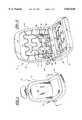
- FIG. 4is a cross-sectional view taken generally along lines 4--4 of FIG. 1 and showing on the left half thereof the subject lumbar support assembly in a retracted condition and in an extended lumbar supporting condition on the right half thereof;
- FIG. 5is a cross-sectional view taken generally along lines 5--5 of FIG. 3 showing the subject lumbar support assembly.
- an automobile seat assemblyis generally indicated at 10.
- the seat assembly 10includes a generally vertical backrest portion 12 and a horizontal seat portion 14.
- the backrest portion 12has a tubular frame 16 positioned along its inner periphery.
- the backrest portion 12is filled with a foam-type cushion 18, which is supported within the frame 16 by a suspension mat-type wire mesh 20, as is known to those skilled in the art.
- the frame 16, cushion 18 and wire mesh 18are all enveloped by a decorative cover 22 made of fabric, leather or other material.
- the wire mesh 20is best shown in FIGS. 2 and 3.
- a lumbar support assemblyis generally shown at 24 in FIGS. 2-5 for selectively applying pressure to the lower area of the backrest portion 12.
- the lumbar support assembly 24includes first 26 and second 28 applicator pads positioned beneath the fabric cover 22 and foam cushion 18 of the backrest portion 12.
- the first and second applicator pads 26, 28are pivotally supported within the backrest portion 12 for generally synchronized movement toward an extended position (right half of FIG. 4) applying outward pressure to the cover 22.
- the first and second applicator pads 26, 28are oriented so as to apply pressure on opposite sides of a seated occupant's spine, in the lower back region.
- the first and second applicator pads 26, 28are each fabricated from a plastic material and include a plurality of apertures formed therein for weight and cost reduction purposes.
- the first and second applicator pads 26, 28each include an arm 30, 32, respectively, extending laterally therefrom.
- the arms 30, 32each comprise a pair of rod-like beams are fabricated from a heavy gauge wire material.
- the applicator pads 26, 28are rigidly connected to the arms 30, 32.
- the applicator pads 26, 28may be articulated or otherwise flexibly connected to the arms 30, 32.
- the arms 30, 32are fixedly connected to respective first and second cranks 34, 36. Therefore, the first crank 34 is operatively connected to the first applicator pad 26 and the second crank 36 is operatively connected to the second applicator pad 28.
- the two cranks 34, 36are identical in construction, thereby minimizing production, tooling and inventory costs, and are preferably fabricated from a durable plastic material.
- Each crank 34, 36includes an arcuate (or otherwise rounded) rim 38 which is grooved much like the rim of a pulley sheave.
- the cranks 34, 36are independently supported for movement upon a bearing surface 40, which surrounds a vertically extending axle section 42 of wire(s) in the wire mesh 20.
- the bearing surface 40permits either relative rotation between the cranks 34, 36 and the axle section 42 of the wire mesh 20, or as in the case of the embodiment as shown in FIGS. 3-5 the bearing surface 40 non-rotatably grips a pair of side-by-side wires, thereby using the inherent torsion spring properties of the wires.
- each crank 34, 36is independently pivotal about an axis (generally vertical) defined by the axle section 42 of the wire(s) of the wire mesh 20.
- its associated arm 30, 32 and connected applicator pad 26, 28swings an arc either toward or away from the lower back of an occupant seated in the seat assembly 10.
- cranks 34, 36can be supported for rotation on a yoke-like support or other feature of the frame 16, instead of the wire mesh 20.
- the lumbar support assemblyis fully independent of the wire mesh 20.
- An actuatorgenerally indicated at 44 in FIGS. 1-5, is provided for selectively manipulating the applicator pads 26, 28 so that an occupant can adjust the amount and degree of lumbar support.
- the actuator 44may take any general form, including electric motor and/or pressurized fluid power assisted, as will become apparent to those skilled in the art.
- the actuator 44preferably comprises a manual input device described in detail below.
- a flexible motion transmitting remote control assemblytransmits motion and forces between the cranks 34, 36 and the actuator 44.
- the motion transmitting remote control assemblyincludes a sheath-like conduit 46 which slidably supports an internal moving core element 48.
- the conduit 46may be of the composite type having an inner tubular liner defining the internal boundaries of a core passage, at least one metallic supportive lay wire wrapped helically about the liner, and an outer cover disposed about the lay wire.
- the core element 48may be either a single wire or a plurality of wire filaments wrapped helically to form a single motion transmitter.
- the conduit 46includes one end 50 operatively connected to the first crank 34, in a pocket thereof.
- the connection between the one end 50 of the conduit 46 and the first crank 34allows compressive forces to be transferred therebetween and resists disconnection.
- An opposite end 52 of the conduit 46is operatively connected to a housing of the actuator 44, as by a clamp or other such fastener.
- a curved section 54forms in the conduit 46 between the actuator 44 and the first crank 34.
- One end of the core element 48is operatively connected to the second crank 36 via a slug 56 seated in a corresponding notch, as best shown in FIG. 5.
- the other end 58 of the core element 48is operatively connected to the actuator 44, such that manipulation of the actuator 44 causes displacement of the core element 48 within the conduit 46.
- the core element 48is shown extending unsheathed from the one end 50 of the conduit 46, around the rim 38 of the first crank 34, through the interior of the backrest portion 12, around the rim 38 of the second crank 36, and finally to the slug 56.
- the core element 48slides over the rim 38 of the first crank 34, and imparts no significant forces thereto.
- the actuator 44functions by applying a tensile force along the core element 48 and at the same time a complimentary compressive reaction force along the conduit 46.
- This contemporaneous pulling force on the core element 48 and pushing force on the conduit 46simultaneously rotates the first 34 and second 36 cranks and thereby displaces the first 26 and second 28 applicator pads in unison against the cover 22 to provide lumbar support to a seated occupant.
- the compressive forceis generated along the conduit 46 by a reaction of the curved section 54 tending to straighten out as the core element 48 is tensioned.
- the compressive forcesare met with immovable resistance at the end 52 anchored to the housing of the actuator 44, via its attachment to the frame 16, while the end 50 butted against the first crank 34 is yieldable via the bearing surface 40 axle section 42 interface.
- the actuator 44preferably includes a manual input device.
- the manual input devicemay include a twist knob 60, and a drum 62 operatively disposed between the one end 58 core element 48 and the twist knob 60.
- the twist knob 60includes a worm gear 64 and the drum 62 includes gear teeth 66 operatively meshing with the worm gear 64.
- Rotation of the twist knob 60drives the drum 62, which in turn winds and unwinds the core element 48 depending upon direction of rotation. This results in an increase or decrease in the tensile forces applied to the core element 48.
- Changes in the mechanical advantage of the twist knob 60can be effected by varying the pitch of the worm gear 64 and/or the pitch circle diameter of the drum gear teeth 66.
- the applicator pads 26, 28are at the unactuated position shown in the left half of FIG. 4.
- the twist knob 60any desired number of revolutions within the range of movement of the components.
- Thiscauses the core element 48 to begin pulling the second crank 36 via the abutment of the slug 56.
- Thispivots the second crank 36 about its wire axle 42 in a clockwise direction as viewed from the right half of FIG. 4, and swings the associated applicator pad 28 into pressing engagement with the occupant's lower back.
- the core element 48is tensioned, and effectively shortened, the bowed section 54 of the conduit 46 is urged to straighten itself.
- This action of the conduit 46results in a compressive force being transmitted along its length, thereby reacting against the first crank 34 and causing it to pivot in the counter clockwise direction, thus swinging its associated applicator pad 26 into pressing engagement with the occupant's lower back.
- both applicator pads 26, 28swing simultaneously into the lower back region of the occupant as the actuator 44 is manipulated.
- the actuator 44restrains the core element 48 relative to the conduit 46, via the worm gear 64 arrangement, thus effectively locking the applicator pads 26, 28 in any displaced position.
- the twist knob 60is rotated in the reverse direction while the occupant gently leans rearwardly against the applicator pads 26, 28, thereby forcing the system to return to its home condition.
- the lumbar support assemblycan be adapted to provide a range of responsiveness to the occupant. For example, by altering the length of the arms 30, 32 and the shape/size of the applicator pads 26, 28, different comfort responses can be achieved. Likewise, by moving the assembly vertically relative seat frame 16, variations in the comfort can be realized. Furthermore, by altering the material and/or diameter of the arms 30, 32, it is possible to increase or decrease their rigidity. In some applications, it may be desirable to limit flexibility of the arms 30, 32, whereas in other situations a high degree of flexibility may be preferred. Similarly, the position of the arms 30, 32 relative to their respective applicator pads 26, 28 has an effect on the flexibility within and along each of the applicator pads 26, 28. For example, in the preferred embodiment, the uppermost and lowermost regions of the applicator pads 26, 28 will likely experience some deflection during use. If this is undesirable, the respective pairs of arms 30, 32 can be spread apart further to more fully reinforce the associated applicator pads 26, 28.
Landscapes
- Engineering & Computer Science (AREA)
- Aviation & Aerospace Engineering (AREA)
- Transportation (AREA)
- Mechanical Engineering (AREA)
- Chair Legs, Seat Parts, And Backrests (AREA)
- Seats For Vehicles (AREA)
Abstract
Description
1. Field of the Invention
The subject invention relates generally to an adjustable lumbar support mechanism concealed within the backrest portion of a seat, and in particular a cable operated mechanism for use in an automobile seat assembly.
2. Description of Related Art
For ergonomic and therapeutic reasons, it is desirable to provide adjustable support to the lower lumbar region of a person's back when seated for long periods of time. As automobile driving often entails long seated periods with only limited movement, lumbar support mechanisms are a welcome addition to many automobile seat assemblies. The lumbar support mechanisms must be adjustable in view of the varying body sizes and shapes of automobile drivers and passengers, as well as the desire to alter one's seat conditions from time to time.
The prior art has advanced many types of adjustable lumbar support mechanisms for the automobile seat environment, including both manually adjusted and powered adjusted units. To help maintain costs low and weight down, manually adjusted lumbar support mechanisms are more often preferred over the powered versions. Examples of manually adjusted lumbar support mechanisms may be had by reference to U.S. Pat. No. 5,076,643, to Colasanti et al., issued Dec. 31, 1991, and U.S. Pat. No. 5,088,790, to Wainwright et al., issued Feb. 18, 1992, both assigned to the assignee of the subject invention, the disclosures of which are hereby incorporated by reference. While nearly all prior art manually adjusted lumbar support mechanisms function satisfactorily, there remains the ever-present desire to further reduce both cost and weight, while maintaining and/or increasing durability, functionality and assembly.
The subject invention comprises an automobile seat assembly including a backrest portion having a structural frame and a cover enveloping the frame. First and second applicator pads are supported within the cover of the backrest portion for generally synchronized movement toward respective extended positions applying outward pressure to the cover. A first crank is operatively connected to the first applicator pad, and a second crank is operatively connected to the second applicator pad. A conduit connects to the first crank, and a core element is slidably disposed within the conduit and connected to the second crank. The improvement of the subject invention comprises an actuator which simultaneously applies a tensile force along the core element and a complimentary compressive force along the conduit to move the first and second cranks and thereby displace the first and second applicator pads in unison against the cover, thus providing lumbar support to a seated occupant.
The subject invention also contemplates an adjustable lumbar support assembly for selectively applying pressure to the lower area of a seat backrest. The assembly comprises a first support wire, a second support wire spaced parallel from the first support wire, a first applicator pad pivotally supported on the first support wire, a second applicator pad pivotally supported on the second support wire, a first crank operatively connected to the first applicator pad, a second crank operatively connected to the second applicator pad, a conduit operatively connected to the first crank, and a core element slidably disposed within the conduit and operatively connected to the second crank. The improvement of the invention comprises an actuator operatively connected to the conduit and the core element for applying a tensile force along the core element and a complimentary compressive force along the conduit to simultaneously move the first and second cranks and thereby displace the first and second applicator pads in unison against the cover providing lumbar support to a seated occupant.
The subject actuator results in a manually adjusted lumbar support mechanism which is particularly inexpensive to construct and substantially lighter than the prior art designs. The subject design is also very durable and can be readily installed in most existing seat constructions.
Other advantages of the present invention will be readily appreciated as the same becomes better understood by reference to the following detailed description when considered in connection with the accompanying drawings wherein:
FIG. 1 is a perspective view of an automobile seat assembly including the lumbar support assembly of the subject invention;
FIG. 2 is a perspective view of the internal frame structure of an automobile seat assembly including the lumbar support assembly of the subject invention operatively supported therein;
FIG. 3 is a fragmentary rear view of the actuator according to the subject invention;
FIG. 4 is a cross-sectional view taken generally alonglines 4--4 of FIG. 1 and showing on the left half thereof the subject lumbar support assembly in a retracted condition and in an extended lumbar supporting condition on the right half thereof; and
FIG. 5 is a cross-sectional view taken generally alonglines 5--5 of FIG. 3 showing the subject lumbar support assembly.
Referring to the Figures, wherein like numerals indicate like or corresponding parts throughout the several views, an automobile seat assembly is generally indicated at 10. Theseat assembly 10 includes a generallyvertical backrest portion 12 and ahorizontal seat portion 14. Thebackrest portion 12 has atubular frame 16 positioned along its inner periphery. Thebackrest portion 12 is filled with a foam-type cushion 18, which is supported within theframe 16 by a suspension mat-type wire mesh 20, as is known to those skilled in the art. Theframe 16,cushion 18 andwire mesh 18 are all enveloped by adecorative cover 22 made of fabric, leather or other material. Thewire mesh 20 is best shown in FIGS. 2 and 3.
A lumbar support assembly is generally shown at 24 in FIGS. 2-5 for selectively applying pressure to the lower area of thebackrest portion 12. Thelumbar support assembly 24 includes first 26 and second 28 applicator pads positioned beneath thefabric cover 22 andfoam cushion 18 of thebackrest portion 12. The first andsecond applicator pads backrest portion 12 for generally synchronized movement toward an extended position (right half of FIG. 4) applying outward pressure to thecover 22. The first andsecond applicator pads second applicator pads
The first andsecond applicator pads arm arms applicator pads arms applicator pads arms
As shown in FIGS. 2-5, thearms second cranks first crank 34 is operatively connected to thefirst applicator pad 26 and thesecond crank 36 is operatively connected to thesecond applicator pad 28. The twocranks crank rim 38 which is grooved much like the rim of a pulley sheave. Thecranks bearing surface 40, which surrounds a vertically extendingaxle section 42 of wire(s) in thewire mesh 20. Thebearing surface 40 permits either relative rotation between thecranks axle section 42 of thewire mesh 20, or as in the case of the embodiment as shown in FIGS. 3-5 thebearing surface 40 non-rotatably grips a pair of side-by-side wires, thereby using the inherent torsion spring properties of the wires. In either case, eachcrank axle section 42 of the wire(s) of thewire mesh 20. As eachcrank arm applicator pad seat assembly 10.
Those skilled in the art will appreciate that in an alternative embodiment, thecranks frame 16, instead of thewire mesh 20. In this application (not shown), the lumbar support assembly is fully independent of thewire mesh 20.
An actuator, generally indicated at 44 in FIGS. 1-5, is provided for selectively manipulating theapplicator pads actuator 44 may take any general form, including electric motor and/or pressurized fluid power assisted, as will become apparent to those skilled in the art. However, theactuator 44 preferably comprises a manual input device described in detail below.
A flexible motion transmitting remote control assembly transmits motion and forces between thecranks actuator 44. The motion transmitting remote control assembly includes a sheath-like conduit 46 which slidably supports an internal movingcore element 48. Theconduit 46 may be of the composite type having an inner tubular liner defining the internal boundaries of a core passage, at least one metallic supportive lay wire wrapped helically about the liner, and an outer cover disposed about the lay wire. However, any such conduit construction or Bowden-type actuator will perform satisfactorily. Thecore element 48 may be either a single wire or a plurality of wire filaments wrapped helically to form a single motion transmitter.
Theconduit 46 includes oneend 50 operatively connected to thefirst crank 34, in a pocket thereof. The connection between the oneend 50 of theconduit 46 and thefirst crank 34 allows compressive forces to be transferred therebetween and resists disconnection. Anopposite end 52 of theconduit 46 is operatively connected to a housing of theactuator 44, as by a clamp or other such fastener. Acurved section 54 forms in theconduit 46 between the actuator 44 and thefirst crank 34. In order for theapplicator pads actuator 44, there must be anunrestrained bow 54 in theconduit 46, as will be more fully described below.
One end of thecore element 48 is operatively connected to the second crank 36 via aslug 56 seated in a corresponding notch, as best shown in FIG. 5. Theother end 58 of thecore element 48 is operatively connected to theactuator 44, such that manipulation of theactuator 44 causes displacement of thecore element 48 within theconduit 46. Referring to FIGS. 3-5, thecore element 48 is shown extending unsheathed from the oneend 50 of theconduit 46, around therim 38 of thefirst crank 34, through the interior of thebackrest portion 12, around therim 38 of the second crank 36, and finally to theslug 56. Thecore element 48 slides over therim 38 of thefirst crank 34, and imparts no significant forces thereto.
The actuator 44 functions by applying a tensile force along thecore element 48 and at the same time a complimentary compressive reaction force along theconduit 46. This contemporaneous pulling force on thecore element 48 and pushing force on theconduit 46 simultaneously rotates the first 34 and second 36 cranks and thereby displaces the first 26 and second 28 applicator pads in unison against thecover 22 to provide lumbar support to a seated occupant. The compressive force is generated along theconduit 46 by a reaction of thecurved section 54 tending to straighten out as thecore element 48 is tensioned. As a result, the compressive forces are met with immovable resistance at theend 52 anchored to the housing of theactuator 44, via its attachment to theframe 16, while theend 50 butted against thefirst crank 34 is yieldable via the bearingsurface 40axle section 42 interface.
As stated above, theactuator 44 preferably includes a manual input device. The manual input device may include atwist knob 60, and adrum 62 operatively disposed between the oneend 58core element 48 and thetwist knob 60. Thetwist knob 60 includes aworm gear 64 and thedrum 62 includesgear teeth 66 operatively meshing with theworm gear 64. Rotation of thetwist knob 60 drives thedrum 62, which in turn winds and unwinds thecore element 48 depending upon direction of rotation. This results in an increase or decrease in the tensile forces applied to thecore element 48. Changes in the mechanical advantage of thetwist knob 60 can be effected by varying the pitch of theworm gear 64 and/or the pitch circle diameter of thedrum gear teeth 66.
In operation, theapplicator pads applicator pads twist knob 60 any desired number of revolutions within the range of movement of the components. This causes thecore element 48 to begin pulling the second crank 36 via the abutment of theslug 56. This, in turn, pivots the second crank 36 about itswire axle 42 in a clockwise direction as viewed from the right half of FIG. 4, and swings the associatedapplicator pad 28 into pressing engagement with the occupant's lower back. As thecore element 48 is tensioned, and effectively shortened, the bowedsection 54 of theconduit 46 is urged to straighten itself. This action of theconduit 46 results in a compressive force being transmitted along its length, thereby reacting against the first crank 34 and causing it to pivot in the counter clockwise direction, thus swinging its associatedapplicator pad 26 into pressing engagement with the occupant's lower back.
Accordingly, bothapplicator pads actuator 44 is manipulated. Theactuator 44 restrains thecore element 48 relative to theconduit 46, via theworm gear 64 arrangement, thus effectively locking theapplicator pads applicator pads twist knob 60 is rotated in the reverse direction while the occupant gently leans rearwardly against theapplicator pads
The lumbar support assembly can be adapted to provide a range of responsiveness to the occupant. For example, by altering the length of thearms applicator pads relative seat frame 16, variations in the comfort can be realized. Furthermore, by altering the material and/or diameter of thearms arms arms respective applicator pads applicator pads applicator pads arms applicator pads
The invention has been described in an illustrative manner, and it is to be understood that the terminology which has been used is intended to be in the nature of words of description rather than of limitation.
Obviously, many modifications and variations of the present invention are possible in light of the above teachings. It is, therefore, to be understood that within the scope of the appended claims, wherein reference numerals are merely for convenience and are not to be in any way limiting, the invention may be practiced otherwise than as specifically described.
Claims (20)
1. An automotive seat assembly comprising:
a backrest portion having a structural frame and a cover enveloping said frame;
first and second applicator pads supported within said cover of said backrest portion for generally synchronized movement toward respective extended positions applying outward pressure to said cover;
a first crank operatively connected to said first applicator pad;
a second crank operatively connected to said second applicator pad;
a conduit operatively connected to said first crank, said conduit having a curved section;
a core element slidably disposed within said conduit and operatively connected to said second crank; and
an actuator operatively connected to said conduit and said core element, for applying a tensile force along said core element,
wherein the curved section of said conduit causes a compressive force along said conduit to move said first crank as the tensile force is applied to said core element to move said second crank, thereby displacing said first and second applicator pads against said cover to provide lumbar support to a seated occupant.
2. An assembly as set forth in claim 1 wherein said first and second cranks each include a grooved arcuate surface.
3. An assembly as set forth in claim 1 wherein said first and second cranks each include a bearing surface, and said frame includes respective axle supports for engaging said bearing surfaces.
4. An assembly as set forth in claim 3 wherein said frame includes a wire mesh supported within said cover of said backrest.
5. An assembly as set forth in claim 4 wherein said axle supports comprise vertically extending sections of said wire mesh.
6. An assembly as set forth in claim 1 wherein said first and second applicator pads include an arm extending laterally to said respective.
7. An assembly as set forth in claim 6 wherein said arm of each of said first and second applicator pads comprises a pair of beams.
8. An assembly as set forth in claim 6 wherein said actuator includes a manual input device.
9. An assembly as set forth in claim 8 wherein said manual input device includes a twist knob.
10. An assembly as set forth in claim 9 wherein said actuator includes a drum operatively disposed between said core element and said twist knob.
11. An assembly as set forth in claim 10 wherein said twist knob includes a worm gear and said drum includes gear teeth operatively meshing with said worm gear.
12. An assembly as set forth in claim 1 wherein said first and second applicator pads are each fabricated from a plastic material and include a plurality of apertures formed therein.
13. An assembly ass et forth in claim 1 wherein said backrest includes a cushion disposed between said first and second applicator pads and said cover.
14. An adjustable lumbar support assembly for selectively applying pressure to a lower area of a seat backrest, said assembly comprising:
a first support wire;
a second support wire spaced parallel from said first support wire;
a first applicator pad pivotally supported on said first support wire;
a second applicator pad pivotally supported on said second support wire;
a first crank operatively connected to said first applicator pad;
a second crank operatively connected said second applicator pad;
a conduit operatively connected to said first crank, said conduit having a curved section;
a core element slidably disposed within said conduit and operatively connected said second crank; and
an actuator operatively connected to said conduit and said core element for applying a tensile force along said core element,
wherein the curved section of said conduit causes a compressive force along said conduit to move said first crank as the tensile force is applied to said core element to move said second crank, thereby displacing said first and second applicator pads against the lower area of the seat backrest to provide lumbar support to a seated occupant.
15. An assembly as set forth in claim 14 wherein said first and second cranks each include a grooved arcuate surface.
16. An assembly as set forth in claim 14 wherein said first and second applicator pads include an arm extending laterally to said respective first and second crank.
17. An assembly as set forth in claim 16 wherein said arm of each of said first and second applicator pads comprises a pair of beams.
18. An assembly as set forth in claim 14 wherein said actuator includes a twist knob having a drum operatively engaging said core element.
19. An assembly as set forth in claim 18 wherein said twist knob includes a worm gear and said drum includes gear teeth operatively meshing with said worm gear.
20. An adjustable lumbar support assembly for selectively applying pressure to a lower area of a seat backrest, said assembly, comprising:
a backrest portion having a structural frame and a cover enveloping said frame;
first and second applicator pads supported within said cover of said backrest portion;
a first crank operatively connected to said first applicator pad;
a second crank operatively connected to said second applicator pad;
a conduit operatively connected to said first crank, said conduit having a curved section;
a core element slidably disposed within said conduit and operatively connected to said second crank; and
an actuator operatively connected to said conduit and said core element,
wherein applying an increase in a tensile force along said core element by said actuator causes the curved section of said conduit to increase a compressive force along said conduit, thereby causing said first and second cranks to increase a pressure applied by said first and second applicator pads against the lower area of the seat backrest, and
wherein applying a decease in the tensile force along said core element by said actuator causes the curved section of said conduit to decrease the compressive force along said conduit, thereby causing said first and second cranks to decrease the pressure applied by said first and second applicator pads against the lower area of the seat backrest.
Priority Applications (1)
| Application Number | Priority Date | Filing Date | Title |
|---|---|---|---|
| US08/847,829US5823620A (en) | 1997-04-17 | 1997-04-17 | Vehicle seat having lumbar support |
Applications Claiming Priority (1)
| Application Number | Priority Date | Filing Date | Title |
|---|---|---|---|
| US08/847,829US5823620A (en) | 1997-04-17 | 1997-04-17 | Vehicle seat having lumbar support |
Publications (1)
| Publication Number | Publication Date |
|---|---|
| US5823620Atrue US5823620A (en) | 1998-10-20 |
Family
ID=25301612
Family Applications (1)
| Application Number | Title | Priority Date | Filing Date |
|---|---|---|---|
| US08/847,829Expired - Fee RelatedUS5823620A (en) | 1997-04-17 | 1997-04-17 | Vehicle seat having lumbar support |
Country Status (1)
| Country | Link |
|---|---|
| US (1) | US5823620A (en) |
Cited By (119)
| Publication number | Priority date | Publication date | Assignee | Title |
|---|---|---|---|---|
| US5954399A (en)* | 1998-07-15 | 1999-09-21 | Hong; Jung-Myung | Lumbar support for a car seat |
| US6052886A (en)* | 1996-12-09 | 2000-04-25 | Atoma International, Inc. | Method of installing a bowden wire assembly and the resulting installation |
| US6068336A (en)* | 1997-11-13 | 2000-05-30 | Bertrand Faure Sitztechnik Gmbh & Co. Kg. | Adjustment mechanism for the side support panels of a seat back |
| US6074006A (en)* | 1999-05-21 | 2000-06-13 | Magna Interior Systems, Inc. | Automotive seat with pneumatic pelvic stabilization |
| US6089664A (en)* | 1996-01-27 | 2000-07-18 | Yoshida; Atsuo | Support for backrest and seat of seat furniture |
| US6152531A (en)* | 1996-08-23 | 2000-11-28 | Youngflex Ag | Seat suspension arrangement and adjustment mechanism therefore |
| US6189972B1 (en)* | 1998-06-05 | 2001-02-20 | Teknion Furniture Systems Inc. | Lumbar support adjustment mechanism |
| US6223622B1 (en) | 2000-01-21 | 2001-05-01 | L&P Property Management Company | Push button cable actuator |
| DE19957965A1 (en)* | 1999-12-02 | 2001-06-07 | Bayerische Motoren Werke Ag | Seat back for motor vehicle has lumbar support section installed on spring-supported frame elastically deformable or displaceable in direction perpendicular to plane of upholstery support surface |
| US6318785B1 (en) | 2000-10-13 | 2001-11-20 | Asc Incorporated | Automotive vehicle foot rest |
| WO2002024033A1 (en) | 2000-09-18 | 2002-03-28 | L & P Property Management Company | Adjustable lumbar support |
| US6402246B1 (en) | 2001-04-11 | 2002-06-11 | L&P Property Management | Simplified strap lumbar support device |
| US6499803B2 (en)* | 2000-03-30 | 2002-12-31 | Aisin Seiki Kabushiki Kaisha | Lumbar support device |
| US20030001424A1 (en)* | 2001-06-27 | 2003-01-02 | David Mundell | Integral elastomeric suspension article and manufacturing process |
| DE10135473A1 (en)* | 2001-07-20 | 2003-02-06 | Itw Automotive Prod Gmbh & Co | Seat for automobiles or the like |
| WO2003034871A1 (en)* | 2001-10-22 | 2003-05-01 | L & P Property Management Company | Apparatus and method for cyclic adjustment of a supporting element in a seat |
| WO2003005859A3 (en)* | 2001-07-11 | 2003-09-04 | Alfmeier Corp | Integrated adjustable lumbar support and trim attachment system |
| US6619739B2 (en)* | 2001-03-01 | 2003-09-16 | L & P Property Management Company | Universal ergonomic support with self-contained actuator |
| US6623076B2 (en) | 1993-06-17 | 2003-09-23 | Schukra-Gerätebau AG | Adjustment apparatus for a resiliently flexible support element of a back rest |
| US6644740B2 (en) | 2000-06-28 | 2003-11-11 | Lear Corporation | Vehicle seat lumbar support system |
| US6652029B2 (en) | 2001-12-20 | 2003-11-25 | L & P Property Management Company | Unitized back plate and lumbar support |
| US6652028B2 (en) | 2001-11-02 | 2003-11-25 | L & P Property Management | Apparatus and method for lumbar support with variable apex |
| US6666511B2 (en) | 1989-08-04 | 2003-12-23 | Schukra Geratebau Ag | Arching mechanism and method of use |
| US6676214B2 (en) | 2001-11-16 | 2004-01-13 | L & P Property Management Company | Method and apparatus for lumbar support with integrated actuator housing |
| US6692074B1 (en) | 2002-12-02 | 2004-02-17 | L & P Property Management Company | Apparatus and method for bi-directional cable adjustment of an ergonomic support |
| US6758522B2 (en) | 2001-03-29 | 2004-07-06 | L&P Property Management Company | Apparatus and method for varying coefficients of friction in a variable apex back support |
| US20040140700A1 (en)* | 2003-01-22 | 2004-07-22 | Mcmillen Robert J. | Fold down seat lumbar support apparatus and method |
| US6779844B2 (en) | 2001-12-14 | 2004-08-24 | L&P Propety Maqnagement Company | Arching lumbar support with weight distribution surface |
| US20040212227A1 (en)* | 2002-09-30 | 2004-10-28 | Mark Farquhar | Vehicle seat having a lumbar support system |
| US6854804B2 (en) | 2001-09-28 | 2005-02-15 | Ficosa North America | Seat bottom support structure |
| KR100492228B1 (en)* | 2002-12-13 | 2005-05-30 | 주식회사다스 | Lumbar support of seat back for vehicle |
| WO2004089693A3 (en)* | 2003-04-03 | 2005-06-02 | Brock M Walker | Seat with adjustable support system |
| US6908153B2 (en) | 2002-12-02 | 2005-06-21 | L&P Property Management Company | Power lumbar support cable apparatus and method |
| US6908152B2 (en) | 2001-12-14 | 2005-06-21 | L & P Property Management Company | Push lumbar support with flexible pressure surface |
| US20050168036A1 (en)* | 2003-12-08 | 2005-08-04 | Johnson Controls Technology Company | Easy lift mechanism for vehicle seats |
| US6938955B2 (en) | 2001-10-11 | 2005-09-06 | L&P Property Management Co. | Power lumbar mechanism |
| US20050200178A1 (en)* | 2004-03-12 | 2005-09-15 | Maxime Arthur Maurice Samain | Lumbar with flexwires in cross |
| US6994399B2 (en)* | 2001-11-28 | 2006-02-07 | L&P Swiss Holding Company | Seat back suspension arrangement |
| US7000986B2 (en) | 2001-09-28 | 2006-02-21 | Ficosa North America | Lumbar support apparatus |
| US20060091705A1 (en)* | 2002-11-08 | 2006-05-04 | Johnson Controls Technology Company | Seat cushion presenter device for folding seat |
| US7052087B2 (en) | 2002-12-09 | 2006-05-30 | L&P Property Management Company | Method and apparatus for a scissors ergonomic support |
| EP1661494A1 (en)* | 2004-11-30 | 2006-05-31 | L&P Swiss Holding Company | Support structure for a seat |
| EP1680984A1 (en)* | 2005-01-12 | 2006-07-19 | L&P Swiss Holding Company | Lumbar support assembly and corresponding seat structure |
| US20060226683A1 (en)* | 2005-04-08 | 2006-10-12 | Alfmeier Corporation | Adjustable lumbar support with extensive configurability |
| US7137664B2 (en) | 2003-01-22 | 2006-11-21 | L&P Property Management Company | Automatically actuating ergonomic support system for a fold down seat |
| US7140680B2 (en) | 2003-01-22 | 2006-11-28 | L&P Property Management Company | Fold down seat lumbar support apparatus and method |
| EP1733649A1 (en)* | 2005-06-15 | 2006-12-20 | L&P Swiss Holding Company | Guiding element, support assembly and corresponding seat structure |
| US20070228798A1 (en)* | 2006-03-31 | 2007-10-04 | 115124 Canada Inc. | Seat structure with elastic suspension |
| US20070236062A1 (en)* | 2006-03-30 | 2007-10-11 | Schukra Of North America, Ltd | Trim foam lumbar |
| US7399036B2 (en) | 2006-12-01 | 2008-07-15 | Sabic Innovative Plastics Ip B.V. | Molded plastic universal seat |
| US20080262398A1 (en)* | 2007-03-09 | 2008-10-23 | Fka Distributing Co. D/B/A Homedics, Inc. | Body massager |
| US7490899B2 (en) | 2006-03-30 | 2009-02-17 | Schukra Of North America | Combination lumbar-bolster system |
| US20090174241A1 (en)* | 2005-02-07 | 2009-07-09 | L&P Swiss Holding Company | Lumbar Support Device |
| US20090236889A1 (en)* | 2005-05-30 | 2009-09-24 | Brose Fahrzeugteile Ghbh & Kg. Coburg | Support with a backrest adjuster device for a motor vehicle seat |
| US7614696B2 (en) | 2006-12-11 | 2009-11-10 | Schukra Of North America | Lumbar system for climate seating |
| US20100066136A1 (en)* | 2008-09-18 | 2010-03-18 | Lear Corporation | Horizontal lumbar suspension for vehicle seats |
| US20100066135A1 (en)* | 2008-09-15 | 2010-03-18 | Lear Corporation | Active head restraint system with lumbar support for vehicle seats |
| US7690726B2 (en) | 2005-01-12 | 2010-04-06 | L&P Swiss Holding Company | Coupling unit and adjusting mechanism using the coupling unit |
| US7775595B2 (en) | 2004-02-06 | 2010-08-17 | Schukra Of North America | Drive mechanism |
| US20100268133A1 (en)* | 2007-11-07 | 2010-10-21 | Maxime Samain | Support assembly and corresponding seat structure |
| US7862119B2 (en) | 2005-04-08 | 2011-01-04 | Alfmeier Prazision Ag Baugruppen Und Systemlosungen | Vehicle seat with lordosis support |
| US20110062757A1 (en)* | 2009-09-14 | 2011-03-17 | Renato Colja | Pelvic and lumbar support |
| US7984949B2 (en) | 2007-04-24 | 2011-07-26 | Schukra Of North America | Lumbar and bolster support for second row seat |
| US7984948B2 (en)* | 2004-07-30 | 2011-07-26 | Schukra Of North America, Ltd. | Modular contour support apparatus |
| US7997650B2 (en) | 2008-02-22 | 2011-08-16 | Schukra Of North America | Constant pressure retreating lumbar system |
| DE102010039353A1 (en)* | 2010-08-16 | 2012-02-16 | Brose Fahrzeugteile Gmbh & Co. Kommanditgesellschaft, Coburg | Seat-back structure for backrest of motor vehicle seat, has backrest frame, which has front side and extends along backrest longitudinal direction |
| DE102010053190A1 (en)* | 2010-12-03 | 2012-06-06 | Brose Fahrzeugteile Gmbh & Co. Kommanditgesellschaft, Coburg | Seat back structure for vehicle seat, has backrest frame, which has front side facing back of user of seat and backrest cushion |
| US20120256455A1 (en)* | 2010-11-10 | 2012-10-11 | Raul Daniel Flores Aguirre | Passenger seat with wire-frame support |
| US8398170B2 (en) | 2006-10-06 | 2013-03-19 | Brock Walker | Active response seating system |
| US8439441B2 (en) | 2010-09-29 | 2013-05-14 | Lear Corporation | Adjustable lumbar assembly for vehicle seats |
| US20140203610A1 (en)* | 2013-01-24 | 2014-07-24 | Ford Global Technologies, Llc | Upper seatback pivot system |
| US20150239381A1 (en)* | 2014-02-26 | 2015-08-27 | Toyota Jidosha Kabushiki Kaisha | Vehicle seat |
| US9193287B2 (en) | 2012-09-13 | 2015-11-24 | Leggett & Platt Canada Co. | Lumbar support system |
| US9193280B2 (en) | 2012-09-13 | 2015-11-24 | Leggett & Platt Canada Co. | Lumbar support system |
| US9199565B2 (en) | 2012-09-13 | 2015-12-01 | Leggett & Platt Canada Co. | Lumbar support system |
| US9604560B1 (en) | 2015-11-13 | 2017-03-28 | Kongsberg Automotive, Inc. | Assembly for adjusting a lumbar region of a seat |
| US9649962B2 (en) | 2013-01-24 | 2017-05-16 | Ford Global Technologies, Llc | Independent cushion extension and thigh support |
| US9707873B2 (en) | 2013-01-24 | 2017-07-18 | Ford Global Technologies, Llc | Flexible seatback system |
| US9707870B2 (en) | 2013-01-24 | 2017-07-18 | Ford Global Technologies, Llc | Flexible seatback system |
| US9756408B2 (en) | 2016-01-25 | 2017-09-05 | Ford Global Technologies, Llc | Integrated sound system |
| US9776543B2 (en) | 2016-01-25 | 2017-10-03 | Ford Global Technologies, Llc | Integrated independent thigh supports |
| US9802512B1 (en) | 2016-04-12 | 2017-10-31 | Ford Global Technologies, Llc | Torsion spring bushing |
| US9809131B2 (en) | 2015-12-04 | 2017-11-07 | Ford Global Technologies, Llc | Anthropomorphic pivotable upper seatback support |
| US9834166B1 (en) | 2016-06-07 | 2017-12-05 | Ford Global Technologies, Llc | Side airbag energy management system |
| US9845029B1 (en) | 2016-06-06 | 2017-12-19 | Ford Global Technologies, Llc | Passive conformal seat with hybrid air/liquid cells |
| US9849817B2 (en) | 2016-03-16 | 2017-12-26 | Ford Global Technologies, Llc | Composite seat structure |
| US9849856B1 (en) | 2016-06-07 | 2017-12-26 | Ford Global Technologies, Llc | Side airbag energy management system |
| US9889773B2 (en) | 2016-04-04 | 2018-02-13 | Ford Global Technologies, Llc | Anthropomorphic upper seatback |
| US9902293B2 (en) | 2013-01-24 | 2018-02-27 | Ford Global Technologies, Llc | Independent cushion extension with optimized leg-splay angle |
| US9914378B1 (en) | 2016-12-16 | 2018-03-13 | Ford Global Technologies, Llc | Decorative and functional upper seatback closeout assembly |
| US9994135B2 (en) | 2016-03-30 | 2018-06-12 | Ford Global Technologies, Llc | Independent cushion thigh support |
| US10035442B2 (en) | 2016-01-25 | 2018-07-31 | Ford Global Technologies, Llc | Adjustable upper seatback module |
| CN108357401A (en)* | 2018-02-09 | 2018-08-03 | 广州汽车集团零部件有限公司 | A kind of motor vehicle seat back waist support regulating device |
| US10046681B2 (en) | 2016-04-12 | 2018-08-14 | Ford Global Technologies, Llc | Articulating mechanical thigh extension composite trim payout linkage system |
| US10046682B2 (en) | 2015-08-03 | 2018-08-14 | Ford Global Technologies, Llc | Back cushion module for a vehicle seating assembly |
| US10046683B2 (en) | 2014-01-23 | 2018-08-14 | Ford Global Technologies, Llc | Suspension seat back and cushion system having an inner suspension panel |
| US10052990B2 (en) | 2016-01-25 | 2018-08-21 | Ford Global Technologies, Llc | Extended seatback module head restraint attachment |
| US10065546B2 (en) | 2014-04-02 | 2018-09-04 | Ford Global Technologies, Llc | Vehicle seating assembly with manual independent thigh supports |
| US10081279B2 (en) | 2016-04-12 | 2018-09-25 | Ford Global Technologies, Llc | Articulating thigh extension trim tensioning slider mechanism |
| US20180272969A1 (en)* | 2017-03-24 | 2018-09-27 | Ts Tech Co., Ltd. | Vehicle seat |
| US10166894B2 (en) | 2016-06-09 | 2019-01-01 | Ford Global Technologies, Llc | Seatback comfort carrier |
| US10166895B2 (en) | 2016-06-09 | 2019-01-01 | Ford Global Technologies, Llc | Seatback comfort carrier |
| US10220737B2 (en) | 2016-04-01 | 2019-03-05 | Ford Global Technologies, Llc | Kinematic back panel |
| US10239431B2 (en) | 2016-09-02 | 2019-03-26 | Ford Global Technologies, Llc | Cross-tube attachment hook features for modular assembly and support |
| US10279714B2 (en) | 2016-08-26 | 2019-05-07 | Ford Global Technologies, Llc | Seating assembly with climate control features |
| US10286818B2 (en) | 2016-03-16 | 2019-05-14 | Ford Global Technologies, Llc | Dual suspension seating assembly |
| US10286824B2 (en) | 2016-08-24 | 2019-05-14 | Ford Global Technologies, Llc | Spreader plate load distribution |
| US10369905B2 (en) | 2014-10-03 | 2019-08-06 | Ford Global Technologies, Llc | Tuned flexible support member and flexible suspension features for comfort carriers |
| US10377279B2 (en) | 2016-06-09 | 2019-08-13 | Ford Global Technologies, Llc | Integrated decking arm support feature |
| US10391910B2 (en) | 2016-09-02 | 2019-08-27 | Ford Global Technologies, Llc | Modular assembly cross-tube attachment tab designs and functions |
| US10427569B2 (en) | 2015-01-26 | 2019-10-01 | Kongsberg Automotive, Inc. | Adjustment mechanism for a seat |
| US10532679B2 (en) | 2017-03-24 | 2020-01-14 | Ts Tech Co., Ltd. | Vehicle seat |
| US10596936B2 (en) | 2017-05-04 | 2020-03-24 | Ford Global Technologies, Llc | Self-retaining elastic strap for vent blower attachment to a back carrier |
| US10625646B2 (en) | 2016-04-12 | 2020-04-21 | Ford Global Technologies, Llc | Articulating mechanical thigh extension composite trim payout linkage system |
| US10632882B2 (en) | 2012-09-13 | 2020-04-28 | Leggett & Platt Canada Co. | Lumbar support system |
| US10654385B2 (en) | 2017-03-24 | 2020-05-19 | Ts Tech Co., Ltd. | Vehicle seat |
| US10758051B2 (en) | 2017-07-28 | 2020-09-01 | Inter-Face Medical Llc | Lower back and posture support device |
| EP4105075A1 (en)* | 2021-05-19 | 2022-12-21 | Adient US LLC | Seat adjustment device for a flexible seat frame and method of use |
| CN117426635A (en)* | 2022-07-21 | 2024-01-23 | 李尔公司 | Seat assembly and support portion |
Citations (2)
| Publication number | Priority date | Publication date | Assignee | Title |
|---|---|---|---|---|
| US5076643A (en)* | 1990-08-20 | 1991-12-31 | Lear Seating Corporation | Lumbar support |
| US5088790A (en)* | 1990-05-21 | 1992-02-18 | Lear Seating Corporation | Adjustable lumbar support mechanism for a vehicular seat |
- 1997
- 1997-04-17USUS08/847,829patent/US5823620A/ennot_activeExpired - Fee Related
Patent Citations (2)
| Publication number | Priority date | Publication date | Assignee | Title |
|---|---|---|---|---|
| US5088790A (en)* | 1990-05-21 | 1992-02-18 | Lear Seating Corporation | Adjustable lumbar support mechanism for a vehicular seat |
| US5076643A (en)* | 1990-08-20 | 1991-12-31 | Lear Seating Corporation | Lumbar support |
Cited By (182)
| Publication number | Priority date | Publication date | Assignee | Title |
|---|---|---|---|---|
| US6666511B2 (en) | 1989-08-04 | 2003-12-23 | Schukra Geratebau Ag | Arching mechanism and method of use |
| US6883867B2 (en) | 1993-06-17 | 2005-04-26 | Schukra Geratebau Ag | Device for adjusting a flexible support element of a backrest |
| US6623076B2 (en) | 1993-06-17 | 2003-09-23 | Schukra-Gerätebau AG | Adjustment apparatus for a resiliently flexible support element of a back rest |
| US6089664A (en)* | 1996-01-27 | 2000-07-18 | Yoshida; Atsuo | Support for backrest and seat of seat furniture |
| US6152531A (en)* | 1996-08-23 | 2000-11-28 | Youngflex Ag | Seat suspension arrangement and adjustment mechanism therefore |
| US6052886A (en)* | 1996-12-09 | 2000-04-25 | Atoma International, Inc. | Method of installing a bowden wire assembly and the resulting installation |
| US6068336A (en)* | 1997-11-13 | 2000-05-30 | Bertrand Faure Sitztechnik Gmbh & Co. Kg. | Adjustment mechanism for the side support panels of a seat back |
| US6260921B1 (en)* | 1998-06-05 | 2001-07-17 | Teknion Furniture Systems, Inc. | Lumbar support adjustment mechanism |
| US6189972B1 (en)* | 1998-06-05 | 2001-02-20 | Teknion Furniture Systems Inc. | Lumbar support adjustment mechanism |
| US5954399A (en)* | 1998-07-15 | 1999-09-21 | Hong; Jung-Myung | Lumbar support for a car seat |
| US6074006A (en)* | 1999-05-21 | 2000-06-13 | Magna Interior Systems, Inc. | Automotive seat with pneumatic pelvic stabilization |
| DE19957965A1 (en)* | 1999-12-02 | 2001-06-07 | Bayerische Motoren Werke Ag | Seat back for motor vehicle has lumbar support section installed on spring-supported frame elastically deformable or displaceable in direction perpendicular to plane of upholstery support surface |
| US6301991B2 (en) | 2000-01-21 | 2001-10-16 | L & P Property Management Company | Push button cable actuator |
| US6223622B1 (en) | 2000-01-21 | 2001-05-01 | L&P Property Management Company | Push button cable actuator |
| US6499803B2 (en)* | 2000-03-30 | 2002-12-31 | Aisin Seiki Kabushiki Kaisha | Lumbar support device |
| US6644740B2 (en) | 2000-06-28 | 2003-11-11 | Lear Corporation | Vehicle seat lumbar support system |
| US6557938B1 (en) | 2000-09-18 | 2003-05-06 | L & P Property Management Company | Adjustable lumbar device |
| WO2002024033A1 (en) | 2000-09-18 | 2002-03-28 | L & P Property Management Company | Adjustable lumbar support |
| US6318785B1 (en) | 2000-10-13 | 2001-11-20 | Asc Incorporated | Automotive vehicle foot rest |
| US6619739B2 (en)* | 2001-03-01 | 2003-09-16 | L & P Property Management Company | Universal ergonomic support with self-contained actuator |
| US6824214B2 (en) | 2001-03-01 | 2004-11-30 | L & P Property Management Company | Universal ergonomic support with self-contained actuator |
| US7077476B2 (en) | 2001-03-01 | 2006-07-18 | L&P Property Management Company | Universal ergonomic support with self-contained actuator |
| US20050035637A1 (en)* | 2001-03-01 | 2005-02-17 | Mcmillen Robert James | Universal ergonomic support with self-contained actuator |
| US6758522B2 (en) | 2001-03-29 | 2004-07-06 | L&P Property Management Company | Apparatus and method for varying coefficients of friction in a variable apex back support |
| US6595585B2 (en) | 2001-04-11 | 2003-07-22 | L&P Property Management Company | Lumbar support device |
| US6402246B1 (en) | 2001-04-11 | 2002-06-11 | L&P Property Management | Simplified strap lumbar support device |
| US20030001424A1 (en)* | 2001-06-27 | 2003-01-02 | David Mundell | Integral elastomeric suspension article and manufacturing process |
| WO2003005859A3 (en)* | 2001-07-11 | 2003-09-04 | Alfmeier Corp | Integrated adjustable lumbar support and trim attachment system |
| US7011369B2 (en) | 2001-07-11 | 2006-03-14 | Alfmeier Corporation | Integrated adjustable lumbar support and trim attachment system |
| US7201446B2 (en) | 2001-07-11 | 2007-04-10 | Alfmeier Corporation | Integrated adjustable lumbar support and trim attachment system |
| US20050023873A1 (en)* | 2001-07-11 | 2005-02-03 | Massara Andrew J. | Integrated adjustable lumbar support and trim attachment system |
| US6837543B2 (en) | 2001-07-20 | 2005-01-04 | Itw Automotive Products Gmbh & Co. Kg | Seat, for automobiles or the like |
| DE10135473A1 (en)* | 2001-07-20 | 2003-02-06 | Itw Automotive Prod Gmbh & Co | Seat for automobiles or the like |
| DE10135473B4 (en)* | 2001-07-20 | 2007-01-04 | Itw Automotive Products Gmbh & Co. Kg | Seat, especially for automobiles |
| US6854804B2 (en) | 2001-09-28 | 2005-02-15 | Ficosa North America | Seat bottom support structure |
| US7000986B2 (en) | 2001-09-28 | 2006-02-21 | Ficosa North America | Lumbar support apparatus |
| US6938955B2 (en) | 2001-10-11 | 2005-09-06 | L&P Property Management Co. | Power lumbar mechanism |
| WO2003034871A1 (en)* | 2001-10-22 | 2003-05-01 | L & P Property Management Company | Apparatus and method for cyclic adjustment of a supporting element in a seat |
| US20040245824A1 (en)* | 2001-11-02 | 2004-12-09 | L & P Property Management Company | Apparatus and method for lumbar support with variable apex |
| US6652028B2 (en) | 2001-11-02 | 2003-11-25 | L & P Property Management | Apparatus and method for lumbar support with variable apex |
| US6676214B2 (en) | 2001-11-16 | 2004-01-13 | L & P Property Management Company | Method and apparatus for lumbar support with integrated actuator housing |
| US6994399B2 (en)* | 2001-11-28 | 2006-02-07 | L&P Swiss Holding Company | Seat back suspension arrangement |
| US6908152B2 (en) | 2001-12-14 | 2005-06-21 | L & P Property Management Company | Push lumbar support with flexible pressure surface |
| US6779844B2 (en) | 2001-12-14 | 2004-08-24 | L&P Propety Maqnagement Company | Arching lumbar support with weight distribution surface |
| US6652029B2 (en) | 2001-12-20 | 2003-11-25 | L & P Property Management Company | Unitized back plate and lumbar support |
| US20060103205A1 (en)* | 2002-09-30 | 2006-05-18 | Mark Farquhar | Vehicle seat having a lumbar support system |
| US6991288B2 (en)* | 2002-09-30 | 2006-01-31 | Lear Corporation | Vehicle seat having a lumbar support system |
| US7128372B2 (en) | 2002-09-30 | 2006-10-31 | Lear Corporation | Vehicle seat having a lumbar support system |
| US20040212227A1 (en)* | 2002-09-30 | 2004-10-28 | Mark Farquhar | Vehicle seat having a lumbar support system |
| US7311358B2 (en) | 2002-11-08 | 2007-12-25 | Johnson Controls Technology Company | Seat cushion presenter device for folding seat |
| US20060091705A1 (en)* | 2002-11-08 | 2006-05-04 | Johnson Controls Technology Company | Seat cushion presenter device for folding seat |
| US6908153B2 (en) | 2002-12-02 | 2005-06-21 | L&P Property Management Company | Power lumbar support cable apparatus and method |
| US6692074B1 (en) | 2002-12-02 | 2004-02-17 | L & P Property Management Company | Apparatus and method for bi-directional cable adjustment of an ergonomic support |
| US7052087B2 (en) | 2002-12-09 | 2006-05-30 | L&P Property Management Company | Method and apparatus for a scissors ergonomic support |
| KR100492228B1 (en)* | 2002-12-13 | 2005-05-30 | 주식회사다스 | Lumbar support of seat back for vehicle |
| US7140680B2 (en) | 2003-01-22 | 2006-11-28 | L&P Property Management Company | Fold down seat lumbar support apparatus and method |
| US7137664B2 (en) | 2003-01-22 | 2006-11-21 | L&P Property Management Company | Automatically actuating ergonomic support system for a fold down seat |
| US6905170B2 (en) | 2003-01-22 | 2005-06-14 | L & P Property Management Company | Fold down seat lumbar support apparatus and method |
| US20040140700A1 (en)* | 2003-01-22 | 2004-07-22 | Mcmillen Robert J. | Fold down seat lumbar support apparatus and method |
| WO2004089693A3 (en)* | 2003-04-03 | 2005-06-02 | Brock M Walker | Seat with adjustable support system |
| US20060103204A1 (en)* | 2003-04-03 | 2006-05-18 | Brock M. Walker | Seat with adjustable support system |
| US7429080B2 (en) | 2003-04-03 | 2008-09-30 | Walker Brock M | Seat with adjustable support system |
| US7448685B2 (en) | 2003-12-08 | 2008-11-11 | Frederick Wilkinson | Easy lift mechanism for vehicle seats |
| US20050168036A1 (en)* | 2003-12-08 | 2005-08-04 | Johnson Controls Technology Company | Easy lift mechanism for vehicle seats |
| US7775595B2 (en) | 2004-02-06 | 2010-08-17 | Schukra Of North America | Drive mechanism |
| WO2005094633A1 (en)* | 2004-03-12 | 2005-10-13 | L & P Property Management Company | Lumbar support structure with cross-bars providing additional support |
| US20050200178A1 (en)* | 2004-03-12 | 2005-09-15 | Maxime Arthur Maurice Samain | Lumbar with flexwires in cross |
| US7252335B2 (en) | 2004-03-12 | 2007-08-07 | L&P Property Management Company | Lumbar with flexwires in cross |
| US7984948B2 (en)* | 2004-07-30 | 2011-07-26 | Schukra Of North America, Ltd. | Modular contour support apparatus |
| US8382204B2 (en) | 2004-07-30 | 2013-02-26 | Schukra of North America Co. | Modular contour support apparatus |
| CN101068490B (en)* | 2004-11-30 | 2010-09-22 | L&P瑞士持有公司 | Support structure for seats |
| US20090302653A1 (en)* | 2004-11-30 | 2009-12-10 | L&P Swiss Holding Company | Support Structure for a Seat |
| WO2006058727A1 (en)* | 2004-11-30 | 2006-06-08 | L & P Swiss Holding Company | Support structure for a seat |
| EP1661494A1 (en)* | 2004-11-30 | 2006-05-31 | L&P Swiss Holding Company | Support structure for a seat |
| US7841661B2 (en) | 2005-01-12 | 2010-11-30 | L&P Swiss Holding Company | Lumbar support assembly and corresponding seat structure |
| EP1680984A1 (en)* | 2005-01-12 | 2006-07-19 | L&P Swiss Holding Company | Lumbar support assembly and corresponding seat structure |
| WO2006074714A1 (en)* | 2005-01-12 | 2006-07-20 | L & P Swiss Holding Company | Lumbar support assembly and corresponding seat structure |
| US7690726B2 (en) | 2005-01-12 | 2010-04-06 | L&P Swiss Holding Company | Coupling unit and adjusting mechanism using the coupling unit |
| US8544953B2 (en) | 2005-01-12 | 2013-10-01 | L&P Swiss Holding Ag | Lumbar support assembly and corresponding seat structure |
| US20090174241A1 (en)* | 2005-02-07 | 2009-07-09 | L&P Swiss Holding Company | Lumbar Support Device |
| US7862119B2 (en) | 2005-04-08 | 2011-01-04 | Alfmeier Prazision Ag Baugruppen Und Systemlosungen | Vehicle seat with lordosis support |
| US20060226683A1 (en)* | 2005-04-08 | 2006-10-12 | Alfmeier Corporation | Adjustable lumbar support with extensive configurability |
| US7823975B2 (en)* | 2005-05-30 | 2010-11-02 | Brose Fahrzeugteile Gmbh & Co Kg, Coburg | Support with a backrest adjuster device for a motor vehicle seat |
| US20090236889A1 (en)* | 2005-05-30 | 2009-09-24 | Brose Fahrzeugteile Ghbh & Kg. Coburg | Support with a backrest adjuster device for a motor vehicle seat |
| WO2006133912A3 (en)* | 2005-06-15 | 2007-03-08 | L&P Swiss Holding Co | Guiding element, support assembly and corresponding seat structure |
| US20090184551A1 (en)* | 2005-06-15 | 2009-07-23 | L&P Swiss Holding Company | Guiding Element, Support Assembly and Corresponding Seat Structure |
| EP1733649A1 (en)* | 2005-06-15 | 2006-12-20 | L&P Swiss Holding Company | Guiding element, support assembly and corresponding seat structure |
| US7490899B2 (en) | 2006-03-30 | 2009-02-17 | Schukra Of North America | Combination lumbar-bolster system |
| US7300106B2 (en)* | 2006-03-30 | 2007-11-27 | Schukra Of North America, Ltd. | Trim foam lumbar |
| US20070236062A1 (en)* | 2006-03-30 | 2007-10-11 | Schukra Of North America, Ltd | Trim foam lumbar |
| US20070228798A1 (en)* | 2006-03-31 | 2007-10-04 | 115124 Canada Inc. | Seat structure with elastic suspension |
| US7396077B2 (en)* | 2006-03-31 | 2008-07-08 | 155124 Canada Inc. | Seat structure with elastic suspension |
| US9049937B2 (en) | 2006-10-06 | 2015-06-09 | Brock Walker | Active response seating system |
| US8398170B2 (en) | 2006-10-06 | 2013-03-19 | Brock Walker | Active response seating system |
| US9675179B2 (en) | 2006-10-06 | 2017-06-13 | Trac Tec, Ltd. | Active response seating system |
| US7399036B2 (en) | 2006-12-01 | 2008-07-15 | Sabic Innovative Plastics Ip B.V. | Molded plastic universal seat |
| US7614696B2 (en) | 2006-12-11 | 2009-11-10 | Schukra Of North America | Lumbar system for climate seating |
| US20080262398A1 (en)* | 2007-03-09 | 2008-10-23 | Fka Distributing Co. D/B/A Homedics, Inc. | Body massager |
| US8394041B2 (en)* | 2007-03-09 | 2013-03-12 | Fka Distributing Co., Llc | Body massager |
| US7984949B2 (en) | 2007-04-24 | 2011-07-26 | Schukra Of North America | Lumbar and bolster support for second row seat |
| US20100268133A1 (en)* | 2007-11-07 | 2010-10-21 | Maxime Samain | Support assembly and corresponding seat structure |
| US8840186B2 (en)* | 2007-11-07 | 2014-09-23 | L&P Swiss Holding Ag | Support assembly and corresponding seat structure |
| US7997650B2 (en) | 2008-02-22 | 2011-08-16 | Schukra Of North America | Constant pressure retreating lumbar system |
| US7857381B2 (en) | 2008-09-15 | 2010-12-28 | Lear Corporation | Active head restraint system with lumbar support for vehicle seats |
| US20100066135A1 (en)* | 2008-09-15 | 2010-03-18 | Lear Corporation | Active head restraint system with lumbar support for vehicle seats |
| US7874616B2 (en) | 2008-09-18 | 2011-01-25 | Lear Corporation | Horizontal lumbar suspension for vehicle seats |
| US20100066136A1 (en)* | 2008-09-18 | 2010-03-18 | Lear Corporation | Horizontal lumbar suspension for vehicle seats |
| US20110062757A1 (en)* | 2009-09-14 | 2011-03-17 | Renato Colja | Pelvic and lumbar support |
| US8454090B2 (en)* | 2009-09-14 | 2013-06-04 | Leggett & Platt Canada Co. | Pelvic and lumbar support system |
| DE102010039353A1 (en)* | 2010-08-16 | 2012-02-16 | Brose Fahrzeugteile Gmbh & Co. Kommanditgesellschaft, Coburg | Seat-back structure for backrest of motor vehicle seat, has backrest frame, which has front side and extends along backrest longitudinal direction |
| US8439441B2 (en) | 2010-09-29 | 2013-05-14 | Lear Corporation | Adjustable lumbar assembly for vehicle seats |
| US20120256455A1 (en)* | 2010-11-10 | 2012-10-11 | Raul Daniel Flores Aguirre | Passenger seat with wire-frame support |
| DE102010053190A1 (en)* | 2010-12-03 | 2012-06-06 | Brose Fahrzeugteile Gmbh & Co. Kommanditgesellschaft, Coburg | Seat back structure for vehicle seat, has backrest frame, which has front side facing back of user of seat and backrest cushion |
| US9764670B2 (en) | 2012-09-13 | 2017-09-19 | Leggett & Platt Canada Co. | Lumbar support system |
| US10632882B2 (en) | 2012-09-13 | 2020-04-28 | Leggett & Platt Canada Co. | Lumbar support system |
| US9193287B2 (en) | 2012-09-13 | 2015-11-24 | Leggett & Platt Canada Co. | Lumbar support system |
| US9193280B2 (en) | 2012-09-13 | 2015-11-24 | Leggett & Platt Canada Co. | Lumbar support system |
| US9199565B2 (en) | 2012-09-13 | 2015-12-01 | Leggett & Platt Canada Co. | Lumbar support system |
| US9873362B2 (en) | 2013-01-24 | 2018-01-23 | Ford Global Technologies, Llc | Flexible seatback system |
| US9126508B2 (en)* | 2013-01-24 | 2015-09-08 | Ford Global Technologies, Llc | Upper seatback pivot system |
| US9707870B2 (en) | 2013-01-24 | 2017-07-18 | Ford Global Technologies, Llc | Flexible seatback system |
| US9707873B2 (en) | 2013-01-24 | 2017-07-18 | Ford Global Technologies, Llc | Flexible seatback system |
| US9902293B2 (en) | 2013-01-24 | 2018-02-27 | Ford Global Technologies, Llc | Independent cushion extension with optimized leg-splay angle |
| US9649962B2 (en) | 2013-01-24 | 2017-05-16 | Ford Global Technologies, Llc | Independent cushion extension and thigh support |
| US20140203610A1 (en)* | 2013-01-24 | 2014-07-24 | Ford Global Technologies, Llc | Upper seatback pivot system |
| US9873360B2 (en) | 2013-01-24 | 2018-01-23 | Ford Global Technologies, Llc | Flexible seatback system |
| US10046683B2 (en) | 2014-01-23 | 2018-08-14 | Ford Global Technologies, Llc | Suspension seat back and cushion system having an inner suspension panel |
| US20150239381A1 (en)* | 2014-02-26 | 2015-08-27 | Toyota Jidosha Kabushiki Kaisha | Vehicle seat |
| US9873364B2 (en)* | 2014-02-26 | 2018-01-23 | Toyota Jidosha Kabushiki Kaisha | Vehicle seat |
| US10065546B2 (en) | 2014-04-02 | 2018-09-04 | Ford Global Technologies, Llc | Vehicle seating assembly with manual independent thigh supports |
| US10369905B2 (en) | 2014-10-03 | 2019-08-06 | Ford Global Technologies, Llc | Tuned flexible support member and flexible suspension features for comfort carriers |
| US10427569B2 (en) | 2015-01-26 | 2019-10-01 | Kongsberg Automotive, Inc. | Adjustment mechanism for a seat |
| US10046682B2 (en) | 2015-08-03 | 2018-08-14 | Ford Global Technologies, Llc | Back cushion module for a vehicle seating assembly |
| US9604560B1 (en) | 2015-11-13 | 2017-03-28 | Kongsberg Automotive, Inc. | Assembly for adjusting a lumbar region of a seat |
| US10239419B2 (en) | 2015-12-04 | 2019-03-26 | Ford Global Technologies, Llc | Anthropomorphic pivotable upper seatback support |
| US9809131B2 (en) | 2015-12-04 | 2017-11-07 | Ford Global Technologies, Llc | Anthropomorphic pivotable upper seatback support |
| US9776543B2 (en) | 2016-01-25 | 2017-10-03 | Ford Global Technologies, Llc | Integrated independent thigh supports |
| US10035442B2 (en) | 2016-01-25 | 2018-07-31 | Ford Global Technologies, Llc | Adjustable upper seatback module |
| US9756408B2 (en) | 2016-01-25 | 2017-09-05 | Ford Global Technologies, Llc | Integrated sound system |
| US10052990B2 (en) | 2016-01-25 | 2018-08-21 | Ford Global Technologies, Llc | Extended seatback module head restraint attachment |
| US9849817B2 (en) | 2016-03-16 | 2017-12-26 | Ford Global Technologies, Llc | Composite seat structure |
| US10286818B2 (en) | 2016-03-16 | 2019-05-14 | Ford Global Technologies, Llc | Dual suspension seating assembly |
| US9994135B2 (en) | 2016-03-30 | 2018-06-12 | Ford Global Technologies, Llc | Independent cushion thigh support |
| US10220737B2 (en) | 2016-04-01 | 2019-03-05 | Ford Global Technologies, Llc | Kinematic back panel |
| US9889773B2 (en) | 2016-04-04 | 2018-02-13 | Ford Global Technologies, Llc | Anthropomorphic upper seatback |
| US10081279B2 (en) | 2016-04-12 | 2018-09-25 | Ford Global Technologies, Llc | Articulating thigh extension trim tensioning slider mechanism |
| US10625646B2 (en) | 2016-04-12 | 2020-04-21 | Ford Global Technologies, Llc | Articulating mechanical thigh extension composite trim payout linkage system |
| US9802512B1 (en) | 2016-04-12 | 2017-10-31 | Ford Global Technologies, Llc | Torsion spring bushing |
| US10046681B2 (en) | 2016-04-12 | 2018-08-14 | Ford Global Technologies, Llc | Articulating mechanical thigh extension composite trim payout linkage system |
| US9845029B1 (en) | 2016-06-06 | 2017-12-19 | Ford Global Technologies, Llc | Passive conformal seat with hybrid air/liquid cells |
| US9849856B1 (en) | 2016-06-07 | 2017-12-26 | Ford Global Technologies, Llc | Side airbag energy management system |
| US9834166B1 (en) | 2016-06-07 | 2017-12-05 | Ford Global Technologies, Llc | Side airbag energy management system |
| US10166894B2 (en) | 2016-06-09 | 2019-01-01 | Ford Global Technologies, Llc | Seatback comfort carrier |
| US10166895B2 (en) | 2016-06-09 | 2019-01-01 | Ford Global Technologies, Llc | Seatback comfort carrier |
| US10377279B2 (en) | 2016-06-09 | 2019-08-13 | Ford Global Technologies, Llc | Integrated decking arm support feature |
| US10286824B2 (en) | 2016-08-24 | 2019-05-14 | Ford Global Technologies, Llc | Spreader plate load distribution |
| US10279714B2 (en) | 2016-08-26 | 2019-05-07 | Ford Global Technologies, Llc | Seating assembly with climate control features |
| US10239431B2 (en) | 2016-09-02 | 2019-03-26 | Ford Global Technologies, Llc | Cross-tube attachment hook features for modular assembly and support |
| US10391910B2 (en) | 2016-09-02 | 2019-08-27 | Ford Global Technologies, Llc | Modular assembly cross-tube attachment tab designs and functions |
| US9914378B1 (en) | 2016-12-16 | 2018-03-13 | Ford Global Technologies, Llc | Decorative and functional upper seatback closeout assembly |
| US10857958B2 (en) | 2017-03-24 | 2020-12-08 | Ts Tech Co., Ltd. | Vehicle seat |
| US10538212B2 (en)* | 2017-03-24 | 2020-01-21 | Ts Tech Co., Ltd. | Vehicle seat |
| US20180272969A1 (en)* | 2017-03-24 | 2018-09-27 | Ts Tech Co., Ltd. | Vehicle seat |
| US12017594B2 (en) | 2017-03-24 | 2024-06-25 | Ts Tech Co., Ltd. | Vehicle seat |
| US10654385B2 (en) | 2017-03-24 | 2020-05-19 | Ts Tech Co., Ltd. | Vehicle seat |
| US11745679B2 (en) | 2017-03-24 | 2023-09-05 | Ts Tech Co., Ltd. | Vehicle seat |
| US10532679B2 (en) | 2017-03-24 | 2020-01-14 | Ts Tech Co., Ltd. | Vehicle seat |
| US10889217B2 (en) | 2017-03-24 | 2021-01-12 | Ts Tech Co., Ltd. | Vehicle seat |
| US11235719B2 (en) | 2017-03-24 | 2022-02-01 | Ts Tech Co., Ltd. | Vehicle seat |
| US11370338B2 (en) | 2017-03-24 | 2022-06-28 | Ts Tech Co., Ltd. | Vehicle seat |
| US10596936B2 (en) | 2017-05-04 | 2020-03-24 | Ford Global Technologies, Llc | Self-retaining elastic strap for vent blower attachment to a back carrier |
| US11432654B2 (en) | 2017-07-28 | 2022-09-06 | Inter-Face Medical Llc | Lower back and posture support device |
| US10758051B2 (en) | 2017-07-28 | 2020-09-01 | Inter-Face Medical Llc | Lower back and posture support device |
| CN108357401B (en)* | 2018-02-09 | 2024-02-23 | 广州汽车集团零部件有限公司 | Car seat back waist holds in palm adjusting device |
| CN108357401A (en)* | 2018-02-09 | 2018-08-03 | 广州汽车集团零部件有限公司 | A kind of motor vehicle seat back waist support regulating device |
| EP4105075A1 (en)* | 2021-05-19 | 2022-12-21 | Adient US LLC | Seat adjustment device for a flexible seat frame and method of use |
| US12049162B2 (en) | 2021-05-19 | 2024-07-30 | Adient Us Llc | Seat adjustment device for a flexible seat frame and method of use |
| CN117426635A (en)* | 2022-07-21 | 2024-01-23 | 李尔公司 | Seat assembly and support portion |
| US20240025314A1 (en)* | 2022-07-21 | 2024-01-25 | Lear Corporation | Seat assembly and support portion |
| US11958391B2 (en)* | 2022-07-21 | 2024-04-16 | Lear Corporation | Seat assembly and support portion |
| DE102023117048B4 (en) | 2022-07-21 | 2024-09-05 | Lear Corporation | Seating arrangement and support section |
| CN117426635B (en)* | 2022-07-21 | 2025-03-28 | 李尔公司 | Seat assembly and support portion |
Similar Documents
| Publication | Publication Date | Title |
|---|---|---|
| US5823620A (en) | Vehicle seat having lumbar support | |
| JP4322212B2 (en) | Method and apparatus for scissors ergonomic support | |
| JP3505178B2 (en) | Adjustable hip support | |
| CN100406301C (en) | Occupant centering ergonomic support apparatus and method | |
| JP4057427B2 (en) | Lumber support device | |
| US6499803B2 (en) | Lumbar support device | |
| US5449219A (en) | Seat arrangements providing adjustable lumbar support | |
| US7357454B2 (en) | Regulating device for a lateral part of a seat | |
| US7201446B2 (en) | Integrated adjustable lumbar support and trim attachment system | |
| CN100528634C (en) | Adjustable seat cushion bolster mechanism | |
| AU681745B2 (en) | Improvements in and relating to seat arrangements providing adjustable support | |
| CN105620316B (en) | It include the seat of the pivotable backrest comprising handrail | |
| US5087098A (en) | Lumbar support device | |
| US6520580B1 (en) | Lumbar support controlling apparatus for a car seat | |
| US5580027A (en) | Cable drive mechanical seat suspension | |
| WO1999055200A1 (en) | An adjustable lumbar seat support | |
| AU2002258768A1 (en) | Lumbar support device | |
| JPH08509399A (en) | Lumbar support adjustment | |
| CN105026207A (en) | Actuator assembly and method for seat adjustment | |
| EP0803400A2 (en) | Vehicle seat lumbar support | |
| US7942479B2 (en) | Combined manual recline and manual lumbar adjustment mechanism | |
| KR102057461B1 (en) | Lumbar support assembly | |
| KR20070118701A (en) | Height adjustment device of the side of the seat and its adjustment method | |
| JPH0819452A (en) | Back part supporting device of seat for vehicle | |
| US3912215A (en) | Seat construction |
Legal Events
| Date | Code | Title | Description |
|---|---|---|---|
| AS | Assignment | Owner name:LEAR CORPORATION, MICHIGAN Free format text:ASSIGNMENT OF ASSIGNORS INTEREST;ASSIGNOR:LE CAZ, CHRISTIAN;REEL/FRAME:008741/0991 Effective date:19970708 | |
| FEPP | Fee payment procedure | Free format text:PAYOR NUMBER ASSIGNED (ORIGINAL EVENT CODE: ASPN); ENTITY STATUS OF PATENT OWNER: LARGE ENTITY | |
| REMI | Maintenance fee reminder mailed | ||
| LAPS | Lapse for failure to pay maintenance fees | ||
| STCH | Information on status: patent discontinuation | Free format text:PATENT EXPIRED DUE TO NONPAYMENT OF MAINTENANCE FEES UNDER 37 CFR 1.362 | |
| FP | Lapsed due to failure to pay maintenance fee | Effective date:20021020 |