US5823390A - Chemical dispensing apparatus having a pivotal actuator - Google Patents
Chemical dispensing apparatus having a pivotal actuatorDownload PDFInfo
- Publication number
- US5823390A US5823390AUS08/540,235US54023595AUS5823390AUS 5823390 AUS5823390 AUS 5823390AUS 54023595 AUS54023595 AUS 54023595AUS 5823390 AUS5823390 AUS 5823390A
- Authority
- US
- United States
- Prior art keywords
- vessel
- nozzle
- fluid
- conveying tube
- actuator nozzle
- Prior art date
- Legal status (The legal status is an assumption and is not a legal conclusion. Google has not performed a legal analysis and makes no representation as to the accuracy of the status listed.)
- Expired - Lifetime
Links
- 239000000126substanceSubstances0.000titleclaimsabstractdescription36
- 238000004891communicationMethods0.000claimsabstractdescription10
- 239000007788liquidSubstances0.000claimsdescription71
- 239000012530fluidSubstances0.000claimsdescription57
- 230000007246mechanismEffects0.000claimsdescription13
- 230000000694effectsEffects0.000claimsdescription12
- 239000000463materialSubstances0.000claimsdescription11
- 238000006073displacement reactionMethods0.000claimsdescription8
- 230000000737periodic effectEffects0.000claimsdescription8
- 230000000007visual effectEffects0.000claimsdescription8
- 238000005086pumpingMethods0.000claimsdescription4
- 230000003247decreasing effectEffects0.000claimsdescription3
- 230000004044responseEffects0.000claimsdescription3
- 238000001514detection methodMethods0.000claimsdescription2
- 238000007599dischargingMethods0.000claimsdescription2
- 239000003990capacitorSubstances0.000description12
- 230000000249desinfective effectEffects0.000description6
- 238000012360testing methodMethods0.000description6
- 101100339482Colletotrichum orbiculare (strain 104-T / ATCC 96160 / CBS 514.97 / LARS 414 / MAFF 240422) HOG1 geneProteins0.000description5
- 238000010586diagramMethods0.000description5
- 238000009434installationMethods0.000description5
- 238000000034methodMethods0.000description5
- 239000004033plasticSubstances0.000description5
- 101100284548Neosartorya fumigata (strain ATCC MYA-4609 / Af293 / CBS 101355 / FGSC A1100) helA geneProteins0.000description4
- 230000009471actionEffects0.000description4
- 230000001877deodorizing effectEffects0.000description4
- 230000000994depressogenic effectEffects0.000description4
- 239000003205fragranceSubstances0.000description4
- 210000002445nippleAnatomy0.000description4
- 239000013618particulate matterSubstances0.000description4
- XLYOFNOQVPJJNP-UHFFFAOYSA-NwaterSubstancesOXLYOFNOQVPJJNP-UHFFFAOYSA-N0.000description4
- 230000007423decreaseEffects0.000description3
- 229920001971elastomerPolymers0.000description3
- 230000003287optical effectEffects0.000description3
- 239000002245particleSubstances0.000description3
- 238000012546transferMethods0.000description3
- 230000008901benefitEffects0.000description2
- 230000002146bilateral effectEffects0.000description2
- 230000005540biological transmissionEffects0.000description2
- 230000001419dependent effectEffects0.000description2
- 239000000645desinfectantSubstances0.000description2
- 230000009977dual effectEffects0.000description2
- 230000006870functionEffects0.000description2
- 230000005484gravityEffects0.000description2
- 238000007373indentationMethods0.000description2
- 239000002184metalSubstances0.000description2
- 238000012986modificationMethods0.000description2
- 230000004048modificationEffects0.000description2
- 230000002028prematureEffects0.000description2
- 230000032258transportEffects0.000description2
- ZAMOUSCENKQFHK-UHFFFAOYSA-NChlorine atomChemical compound[Cl]ZAMOUSCENKQFHK-UHFFFAOYSA-N0.000description1
- 210000004128D cellAnatomy0.000description1
- LFQSCWFLJHTTHZ-UHFFFAOYSA-NEthanolChemical compoundCCOLFQSCWFLJHTTHZ-UHFFFAOYSA-N0.000description1
- 206010034962PhotopsiaDiseases0.000description1
- 238000010521absorption reactionMethods0.000description1
- 230000003213activating effectEffects0.000description1
- 230000004913activationEffects0.000description1
- 239000000443aerosolSubstances0.000description1
- 230000003115biocidal effectEffects0.000description1
- 230000008859changeEffects0.000description1
- 229910052801chlorineInorganic materials0.000description1
- 239000000460chlorineSubstances0.000description1
- 238000004140cleaningMethods0.000description1
- 239000013013elastic materialSubstances0.000description1
- 238000001914filtrationMethods0.000description1
- 238000011010flushing procedureMethods0.000description1
- 238000005286illuminationMethods0.000description1
- 238000001746injection mouldingMethods0.000description1
- 238000004519manufacturing processMethods0.000description1
- 238000004377microelectronicMethods0.000description1
- 230000008569processEffects0.000description1
- 238000012545processingMethods0.000description1
- 230000009467reductionEffects0.000description1
- 230000001105regulatory effectEffects0.000description1
- 229920002379silicone rubberPolymers0.000description1
- 239000004945silicone rubberSubstances0.000description1
- 239000004094surface-active agentSubstances0.000description1
- 230000007704transitionEffects0.000description1
Images


Classifications
- E—FIXED CONSTRUCTIONS
- E03—WATER SUPPLY; SEWERAGE
- E03D—WATER-CLOSETS OR URINALS WITH FLUSHING DEVICES; FLUSHING VALVES THEREFOR
- E03D9/00—Sanitary or other accessories for lavatories ; Devices for cleaning or disinfecting the toilet room or the toilet bowl; Devices for eliminating smells
- E03D9/02—Devices adding a disinfecting, deodorising, or cleaning agent to the water while flushing
- E03D9/03—Devices adding a disinfecting, deodorising, or cleaning agent to the water while flushing consisting of a separate container with an outlet through which the agent is introduced into the flushing water, e.g. by suction ; Devices for agents in direct contact with flushing water
- E03D9/031—Devices connected to or dispensing into the flushing pipe
- A—HUMAN NECESSITIES
- A47—FURNITURE; DOMESTIC ARTICLES OR APPLIANCES; COFFEE MILLS; SPICE MILLS; SUCTION CLEANERS IN GENERAL
- A47K—SANITARY EQUIPMENT NOT OTHERWISE PROVIDED FOR; TOILET ACCESSORIES
- A47K5/00—Holders or dispensers for soap, toothpaste, or the like
- A47K5/06—Dispensers for soap
- A47K5/12—Dispensers for soap for liquid or pasty soap
- A47K5/1217—Electrical control means for the dispensing mechanism
Definitions
- Deodorizing and disinfecting treatment systems for urinals and toilet bowlsare known in the art and are typically wall mounted units having wick-type dispensing systems that periodically allow drops of olfactory and biocidal fluid to flow through a tube and onto the surface to be treated, such as onto the inside of the toilet bowl or the inside wall of a urinal.
- the wicksare generally mounted to absorb fluid from a gravity-fed liquid reservoir, while another end of the wick is positioned to drip into a flow tube or other liquid guiding mechanism. At least a portion of the wick is exposed to facilitate odorizing of the surrounding area within a room.
- the wickserves as the liquid transfer mechanism between the reservoir, the flow tube and the odorizing medium.
- FIG. 5is a block diagram of an integrated circuit for use as part of a control circuit according to the present invention.
- the nozzle assembly 20is shown generally in FIGS. 3 and 4A.
- the nozzle 22is slidingly and pivotally mounted within the pair of guides 30 attached to the motor plate 31. This allows the nozzle 22 to slide or to be reciprocally displaced in a vertical direction relative to the housing, as shown by arrow 115 of FIGS. 2-3.
- the nozzle 22is also capable of outward pivotal movement relative to the housing 12 to permit reciprocal engagement and disengagement of the bottle 34, as shown by arrow 116 of FIGS. 3 and 4E.
- the guides 30each are formed as "L-shaped" brackets that project outwardly and away from the motor plate 31 to which they are mounted (FIG. 3).
- the guides 30may be constructed from plastic, metal or any other suitable material.
- Each guide 30includes a guide base 118 and a guide mount portion 120 outwardly projecting from the guide base at right angles.
- the guide base 118is secured to the motor plate 31 by screws, rivets, bolts, welds or any other suitable method.
- Two guide mount portions 120opposingly face each other so that the nozzle 22 may be mounted therebetween.
- Each guide mount portion 120comprises a vertical groove or channel 122 disposed along its center, as best shown in FIG. 4A.
- the nozzle 22includes two tabs 128 outwardly projecting from opposite sides of the nozzle, which tabs are configured to communicate with the corresponding channels 122 disposed in the guide mount portions 120.
- the tabs 128 on each side of the nozzleform a releasable interference fit with the channels 122 sufficient to retain the nozzle in place while allowing simple hand pressure to vertically displace the nozzle.
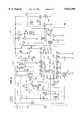
- FIG. 5is a block diagram generally depicting an integrated circuit (IC) 300 and FIG. 6 is a schematic diagram implementing the integrated circuit shown in FIG. 5.
- the integrated circuit 300is used as part of a control circuit 302 for operating the dispensing apparatus 10.
- the IC 300is preferably a model TC-2020 chip manufactured by Holtek Microelectronics Inc., Taiwan. However, any suitably programmed microcomputer or other discrete circuitry may also be used.
- the IC 300includes an oscillator circuit 304 for providing oscillator output signals OSC2 306, OSC3 308 and OSC4 310, and for receiving a variable oscillator input signal OSC1 312.
- the oscillator circuit 304provides a frequency output signal 324 to a divider "A" circuit 328 which divides the frequency output signal by a value of 1024 to produce a divider "A" first output signal 330.
- the number of pulses or the frequency of the output signal 324varies in accordance with resistance and capacitance changes that are selectable by the user through a selectable switching arrangement in conjunction with the signals OSC1 312, OSC2 306, OSC3 308 and OSC4 310, as will be described hereinafter.
- An input control circuit 340receives various inputs, such as TEST 350, CDS 352, OFF 354, RESET 356, CONT1 360, CONT2 362 DAY/NIGHT 364 and BATT 368.
- the input control circuit 340generates an input control first output signal 380 which controls a divider "B" circuit 384.
- the divider "B” circuit 384receives its frequency input from the divider "A" first output signal 330 and divides that frequency by a value of 1024.
- the divider "B” circuit 384then produces a divider "B” output signal 386 under control of the input control circuit 340.
- the output control circuit 392provides an output pulse signal OP 410 to activate a drive motor 412 to periodically depress the nozzle 22. For example, during normal operation, a pulse interval of a predetermined number of counts that correspond to approximately 15 minutes is set so that an output pulse OP 410 occurs every 15 minutes to eject liquid 38 from the bottle 34.
- the output control circuit 392also receives a counter & latch signal 422 from the counter & latch circuit 396 that indicates when a predetermined time-out period has occurred, such as when a total of 3,072 pulses have been output (e.g. the bottle 34 is empty) so that the drive motor 412 may be inhibited and the user notified to replace the bottle.
- the divider "A" 328divides the frequency output signal 324 from the oscillator circuit 304 into a visual flash pulse signal to drive a first LED drive circuit 440 and a second LED drive circuit 442.
- the first and second LED drive circuits 440 and 442activate and deactivate a first LED 446 and a second LED 448, respectively.
- a maximum pulse count signal 450is latched by the counter & latch circuit 396 at a maximum counter value corresponding to when a refill of the bottle 34 is required, such as when the count equals 3072. This corresponds to a bottle empty condition.
- the maximum pulse count signal 450is coupled to the second LED driver circuit 442 and directs the second LED driver circuit 442 to activate the second LED 448 to provide a visual indication corresponding to the bottle empty condition.
- the oscillator circuit 304includes a bilateral switch block 480 which contains a switch “A” 482 and a switch “B” 484. Switch “A” and switch “B” 482, 484 are controlled by a switch control signal 486 generated by the counter & latch circuit 346 that allows the oscillator circuit 304 to operate in one of two predetermined modes.
- an oscillator "A” 488is operational.
- the oscillator "A” 488includes the input signal OSC1 312 and the output signals OSC2 306 and OSC3 308, while an oscillator “B” 490 includes the input signal OSC1 and the output signals OSC2 306 and OSC4 310.
- the switch control signal 486is issued to instruct the bilateral switch block 480 to switch to an oscillator "B" mode.
- the generation of particular frequencies for the oscillator circuit 304will be described in greater detail hereinafter with respect to the circuit diagram of FIG. 6.
- the control circuit 302includes a memory backup circuit 500 formed by a diode D1 and a capacitor C1 to provide a suitable voltage level to the IC 300 when power is removed.
- a power supply circuit 502includes an "ON/OFF" switch S1 coupled to a current limiting resistor R1.
- the current limiting resistor R1couples to a filtering capacitor C2 and a diode D2.
- a three volt DC source of powersuch as the batteries 196, supply three volts to the diode D2 and is labeled Power Line A.
- a reset circuit 504 formed by a "RESET” momentary switch S2 and a capacitor C3allows the IC 300 to be manually reset upon the depression of the RESET switch S2. For example, when the bottle 34 is empty, a new bottle is inserted into the apparatus 10 and the user then resets the control circuitry 302 to again begin the timing and control process.
- a light sensing circuit 508includes a photo-sensitive element, such as a photo resistor R2, which has a resistance that varies with the amount of light sensed by the resistor R2.
- An "AUTO/24 HR" switch S3allows selection between continuous operation (24 hour continuous operation) and automatic operation (operation dependent on lighting conditions).
- the power line Aconnects to the CDS pin 352 in the IC 300 through a diode D3 thereby bypassing the photo resistor R2. This indicates to the input control circuit 340 that a continuous twenty-four hour operation has been selected.
- the diode D3is coupled to a diode D4 and a current limiting resistor R4 that, in turn, is coupled to ground.
- the resistors R3 and R4serve as current limiting resistors.
- switch S3When operating in the automatic mode (switch S3 is open), a variable voltage level on the CDS pin 352 indicates the amount of light detected, and the output pin OP 410 is controlled in response thereto.
- a "DAY/NIGHT" switch S4allows the user to select between a day and a night mode of operation.
- the DAY/NIGHT switch S4in combination with the AUTO/24 HR switch S3 provides a selectable daytime mode or nighttime mode.
- the AUTO/24 HR switch S3is opened, indicating the automatic mode.
- the apparatus 10is responsive to the amount of light detected, as indicated by the voltage level present on the CDS pin 352.
- the AUTO/24 HR switch S3is closed and the control circuit 302 generates an output pulse OP 410 approximately every fifteen minutes during both morning and night conditions, regardless of lighting conditions. No sequence of four pulses OP 410 is generated during the morning and night transition periods.
- This increased frequencycauses the counters and dividers 340, 328 and 384 to operate at an increased frequency and causes the maximum count value to be reached sooner than in the normal mode of operation.
- Such a conditionrepresents a heavy mode of operation where activation of the nozzle 22 occurs at twice the rate as in the normal mode of operation.
- the CONT2 pin 352is tied high so that a maximum count of output pulses OP 410 (ejections from the nozzle 22) must equal 3072 before the input control circuit 340 determines that the bottle 34 is empty. High and low voltage levels may be applied to CONT2 pin 352 can vary the maximum count, thus varying the output of pulses on OP 410.
- the visual indicating mode of the first and second LEDs 151 and 152may be reversed by simple reconfiguration of the CONT1 pin 360. If the CONT1 pin 360 is tied low instead of high, the first LED 151 will not flash when a low power condition is sensed but rather, will flash only when the battery voltage level is sufficient.
- an AC/DC adapter(not shown) may be incorporated into the apparatus 10 so that the dispensing device may be plugged into an AC wall socket, as is well known in the art.
- the oscillating buzzer circuit 418generates an audible tone when the output pin BZB 416 is driven high. This occurs when the counter & latch circuit 396 counts to the maximum pulse count of 3072 OP pulses, thereby audibly indicating that the bottle 34 is empty.
- the BZB pin 416is coupled to the base of a transistor Q5 through a current limiting resistor R22. When the BZB pin 416 is activated, the transistor Q5 oscillates and amplifies the signal to produce an audible tone through an audio speaker SP1.
- the audio speaker SP1 and an inductor L1are connected in parallel between the collector of the transistor Q5 and the power line A. If the CONT1 pin 350 is connected to ground, the audio feature is disabled.
- a "TONE/QUIET” switch S8when closed, connects the base of the transistor Q5 to ground thereby turning-off the transistor Q5 to prevent the audible tone from occurring.
- the switch S8allows the user to select between a quiet mode and an audible tone mode.
- the control circuit 302receives power through the ON/OFF switch S1 which connects the 3-volt battery supply (Power Line A) to the control circuit.
- the apparatus 10is controlled so that the nozzle 22 will be periodically depressed to dispense approximately 28 ounces of liquid 38 in a 31-day period.
- the pumpe.g., nozzle 22 and stem 36
- a predetermined countis selected which corresponds to the number of depressions necessary to dispense the entire amount of liquid during that 31-day period. Once the predetermined count is reached, for example 3072 depressions of the nozzle 22, the second LED 152 is activated.
- FIG. 7shows the hose insert or restrictor insert 114 in greater detail where the hose insert is shown secured within the conveying tube 90.
- the conveying tube 90has an outside diameter 600 and an inside diameter 602 which may change slightly along its length since the material from which the conveying tube is formed is elastic or deformable in nature. Thus, the conveying tube 90 may deform under the pressure of the liquid 38 ejected into the conveying tube.
- the conveying tube 90may, for example, be formed from soft plastic or rubber such as silicone rubber or surgical-type rubber tubing. However, any suitable elastic or rubber material may be used.
- the restrictor insert 114is configured to selectively regulate the volume of liquid 38 ejected into the conveying tube 90 and hence, the liquid back pressure.
- the conveying tube 90is defined as having a source end 610 for receiving the liquid 38 from the nozzle 22 and the pump mechanism 37, and a drain end 612 for discharging the liquid into the nipple 98.
- the ability to regulate the volume of liquid 38 ejected by the nozzle 22 and the ability to regulate and maintain a predetermined level of liquid back pressureis extremely advantageous. Several conditions exist which necessitate use of the restrictor insert 114.
- the conveying tube 90eventually terminates at its suitable destination device (not shown) which may, for example, be a urinal, a toilet and the like.
- suitable destination devicemay, for example, be a urinal, a toilet and the like.
- Such deviceswhen activated or flushed, tend to create a vacuum further increasing the vacuum which may already be present within the conveying tube 90.
- the siphon effect described aboveis further increased when the destination device is flushed which may also result in premature emptying of the bottle. This effect may be amplified during simultaneous liquid ejection and destination device flushing since the vacuum or siphon effect acts upon an "open" nozzle 22.
- the siphon effectdoes not present problems.
- the nozzle 22may not be functioning properly and may become temporarily unseated after liquid 38 has been ejected. Dirt and particulate matter may cause the nozzle 22 to temporarily jam, thus allowing liquid 38 to be drawn out of the bottle 34 between ejections. If the nozzle 22 becomes temporarily jammed (in an open or "leaky” state), the siphon effect can drain a significant portion of the liquid 38 from the bottle 34.
- the restrictor insert 114reduces or eliminates the additional volume of liquid discharged due to the above-described act.
- the nozzle 22 and the pump mechanism 37perform optimally when a predetermined amount of back pressure is created within the conveying tube 90 during liquid ejection.
- back pressurein part, is due the elastic nature of the conveying tube 90.
- the amount of back pressure requireddepends upon the size of the nozzle orifice (not shown). For reasons of manufacturability, different nozzles 22 may be interchanged, which may have different diameter orifices. To insure optimal nozzle 22 performance, the back pressure must be adjusted for each different nozzle type.
- the restrictor insert 114provides a method for adjusting and maintaining the required amount of back pressure within the conveying tube 90.
- the restrictor insert 114shown generally.
- the restrictor insert 114includes a head portion 620, a tail portion 622 and a central portion 624 connected between the head portion and the tail portion.
- the head portion 620, the tail portion 622 and the central portion 624are preferably integrally formed using injection molding or other suitable heat processing techniques.
- the head portion 620has an outside diameter 630 slightly greater than the inside diameter 602 of the conveying tube 90 to form an interference fit with the conveying tube. Since the conveying tube 90 is formed from relatively elastic material, the conveying tube essentially "stretches" or deforms around the head portion 620. Such deformation, in part, tends to retain the restrictor insert 114 vertically in place.
- the head portion 620also provides a "self-cleaning" feature. Particulate matter and dirt may accumulate or may be dispensed into the conveying tube 90 during liquid ejection, which could clog typical devices. However, such particulate matter tends to become trapped between the outside surface of the head portion 620 and the conveying tube 90 where the elastic nature of the conveying tube traps the particles in place. The liquid 38 is able to flow around any trapped particulate matter.
- back pressureThe above-described pressure created within the conveying tube 90 between the nozzle 22 and the restrictor insert 114 is referred to as "back pressure" and is required for optimal nozzle 22 performance.
- the amount of back pressureis adjustable through selective vertical placement of the restrictor insert 114 within the conveying tube 90.
- the amount of back pressureis inversely proportional to the total amount of deformation of the conveying tube 90 and is dependent upon the diameter and the length of the conveying tube subject to deformation.
- the restrictor insert 114is placed relatively far from the nozzle 22, a large portion of the length of the conveying tube 90 is subject to deformation and hence, the amount of back pressure is small. If the restrictor insert 114 is placed relatively close to the nozzle 22, a small portion of the length of the conveying tube 90 is subject to deformation and hence, the amount of back pressure is great. By selecting the appropriate vertical position within the conveying tube 90 to fixedly place the restrictor insert 114, the back pressure to which the nozzle 22 is subject can be selectively regulated and maintained.
- the ability to selectively regulate the amount of back pressure by appropriate vertical placement of the restrictor insert 114may, for example, modify the volume of liquid pumped over time by about between 5% to 20%. Thus, in a selected period of time, the amount of liquid ejected can be modified by up to 20%.
- increasing the diameter of the conveying tube 90 and the restrictor insert 114decreases the amount of back pressure while reducing the diameter of the conveying tube and the restrictor insert increases the amount of back pressure.
- the amount of back pressuremay be adjusted by changing the degree of elasticity of the conveying tube 90 by appropriate selection of material. Increasing the elasticity of the conveying tube 90 decreases the back pressure while decreasing the elasticity increases the back pressure.
Landscapes
- Health & Medical Sciences (AREA)
- Public Health (AREA)
- Epidemiology (AREA)
- Life Sciences & Earth Sciences (AREA)
- Engineering & Computer Science (AREA)
- Hydrology & Water Resources (AREA)
- Water Supply & Treatment (AREA)
- Devices For Dispensing Beverages (AREA)
Abstract
Description
Claims (37)
Priority Applications (3)
| Application Number | Priority Date | Filing Date | Title |
|---|---|---|---|
| US08/540,235US5823390A (en) | 1995-10-06 | 1995-10-06 | Chemical dispensing apparatus having a pivotal actuator |
| PCT/US1995/013292WO1997012834A1 (en) | 1995-10-06 | 1995-10-10 | Chemical dispensing apparatus having a pivotal actuator |
| AU40018/95AAU4001895A (en) | 1995-10-06 | 1995-10-10 | Chemical dispensing apparatus having a pivotal actuator |
Applications Claiming Priority (1)
| Application Number | Priority Date | Filing Date | Title |
|---|---|---|---|
| US08/540,235US5823390A (en) | 1995-10-06 | 1995-10-06 | Chemical dispensing apparatus having a pivotal actuator |
Publications (1)
| Publication Number | Publication Date |
|---|---|
| US5823390Atrue US5823390A (en) | 1998-10-20 |
Family
ID=24154581
Family Applications (1)
| Application Number | Title | Priority Date | Filing Date |
|---|---|---|---|
| US08/540,235Expired - LifetimeUS5823390A (en) | 1995-10-06 | 1995-10-06 | Chemical dispensing apparatus having a pivotal actuator |
Country Status (3)
| Country | Link |
|---|---|
| US (1) | US5823390A (en) |
| AU (1) | AU4001895A (en) |
| WO (1) | WO1997012834A1 (en) |
Cited By (83)
| Publication number | Priority date | Publication date | Assignee | Title |
|---|---|---|---|---|
| WO2001019720A1 (en)* | 1999-09-15 | 2001-03-22 | Technical Concepts, L.P. | System and method for programmably dispensing material |
| US6390329B1 (en)* | 2000-10-10 | 2002-05-21 | Joseph S. Kanfer | Apparatus for hands-free dispensing of a measured quantity of material |
| US6550269B2 (en)* | 2000-02-16 | 2003-04-22 | The Coca-Cola Company | Dispensing apparatus with directional LED lighting |
| US6595389B2 (en)* | 2000-12-23 | 2003-07-22 | Ing. Erich Pfeiffer Gmbh | Device for detecting the operation of a dispenser and the dispenser |
| US6644507B2 (en) | 2001-03-14 | 2003-11-11 | Johnsondiversey, Inc. | Automatic air freshener with dynamically variable dispensing interval |
| US20040050959A1 (en)* | 2002-05-28 | 2004-03-18 | Mazooji Amber N. | Automated cleansing sprayer |
| US20050000551A1 (en)* | 2003-06-23 | 2005-01-06 | Mcintyre Carrie Lilley | Dishwasher liquid delivery systems |
| US20050224596A1 (en)* | 2003-07-08 | 2005-10-13 | Panopoulos Peter J | Machine that is an automatic pesticide, insecticide, repellant, poison, air freshener, disinfectant or other type of spray delivery system |
| US20050247735A1 (en)* | 2004-05-10 | 2005-11-10 | Muderlak Kenneth J | Apparatus and method for dispensing post-foaming gel soap |
| US6979096B2 (en) | 2003-03-11 | 2005-12-27 | The Coca-Cola Company | LED lighting for proportion blending system |
| US20060131329A1 (en)* | 2003-12-16 | 2006-06-22 | Sayers Richard C | Electronically keyed dispensing systems and related methods of installation and use |
| US7108199B1 (en)* | 2005-10-19 | 2006-09-19 | Brown Peter M | Device for dispensing liquid scent |
| USD535004S1 (en) | 2005-10-11 | 2007-01-09 | S. C. Johnson & Son, Inc. | Cover plate for a fragrance dispenser |
| USD537929S1 (en) | 2004-07-01 | 2007-03-06 | Technical Concepts, Llc | Dispenser |
| USD541921S1 (en) | 2004-07-01 | 2007-05-01 | Technical Concepts, Llc | Dispenser |
| US20070095941A1 (en)* | 2005-11-03 | 2007-05-03 | Gorres Geoffrey H | Scent dispensing apparatus |
| EP1808537A1 (en) | 2006-01-16 | 2007-07-18 | Aromania Fragancias Naturales, S.L. | Dual-purpose machine for air freshening and hygienic cleansing |
| US20080185399A1 (en)* | 2007-02-01 | 2008-08-07 | Simplehuman, Llc | Electric soap dispenser |
| US20080185396A1 (en)* | 2007-02-01 | 2008-08-07 | Frank Yang | Electric Soap Dispenser |
| US20080185398A1 (en)* | 2007-02-01 | 2008-08-07 | Simplehuman, Llc | Electric soap dispenser |
| USD580039S1 (en)* | 2007-05-25 | 2008-11-04 | Pestco, Inc. | Dispenser cabinet for deodorant |
| USD582027S1 (en) | 2007-08-16 | 2008-12-02 | Sara Lee Household And Body Care Nederland B.V. | Air deodorising apparatus |
| US20090095331A1 (en)* | 2007-10-12 | 2009-04-16 | General Electric Company | Multiple compartments wash additives auto-dispenser in washer or dryer pedestal |
| US20090095028A1 (en)* | 2007-10-12 | 2009-04-16 | General Electric Company | Bulk dispense user adjustable controls |
| US20090184432A1 (en)* | 2008-01-18 | 2009-07-23 | Georgia-Pacific Consumer Products Lp | Air Freshener Device And Methods For Controlling An Amount Of Evaporated Scented Material Emitted From The Air Freshener Device |
| US20090236362A1 (en)* | 2008-03-24 | 2009-09-24 | Helf Thomas A | Volatile material dispenser |
| US20090266751A1 (en)* | 2003-10-29 | 2009-10-29 | Idex Health & Science Llc | Dosing engine and cartridge apparatus for liquid dispensing and method |
| US20090266753A1 (en)* | 2008-02-26 | 2009-10-29 | David Johnson | Dispensing System for Microbial Solution |
| US20090284157A1 (en)* | 2006-01-09 | 2009-11-19 | Whirlpool Corporation | Control for a refrigerator door dispenser light |
| US20100025427A1 (en)* | 2008-07-25 | 2010-02-04 | Technical Concepts Llc | Dual substance dispenser |
| US20100059602A1 (en)* | 2008-09-09 | 2010-03-11 | Technical Concepts, Llc | Substance dispenser |
| US7690540B1 (en)* | 2005-03-10 | 2010-04-06 | Owens John J | Liquid animal scent dispenser |
| US7775458B2 (en) | 2001-04-13 | 2010-08-17 | S.C. Johnson & Son, Inc. | Automated cleansing sprayer |
| US7837065B2 (en) | 2004-10-12 | 2010-11-23 | S.C. Johnson & Son, Inc. | Compact spray device |
| US20100294852A1 (en)* | 2009-05-21 | 2010-11-25 | Banco Michael J | Methods of Dispensing Two or More Volatile Materials |
| USD629236S1 (en) | 2010-05-21 | 2010-12-21 | Rubbermaid Commercial Products, Llc | Liquid dispenser |
| USD629237S1 (en) | 2010-05-21 | 2010-12-21 | Rubbermaid Commercial Products, Llc | Liquid dispenser |
| US20110095051A1 (en)* | 2009-10-28 | 2011-04-28 | Wei-Ta Liao | Structure of automatic foam soap dispenser |
| US20110101032A1 (en)* | 2009-10-29 | 2011-05-05 | Hokwang Industries Co., Ltd. | Pressing structure of soap dispenser capable of adjusting output soap amount |
| US20110114669A1 (en)* | 2009-11-18 | 2011-05-19 | Simplehuman, Llc | Soap dispenser |
| US8056747B2 (en) | 2007-10-12 | 2011-11-15 | General Electric Company | Removable tank for laundry bulk dispenser system |
| US8061562B2 (en) | 2004-10-12 | 2011-11-22 | S.C. Johnson & Son, Inc. | Compact spray device |
| USD659452S1 (en) | 2011-03-04 | 2012-05-15 | Simplehuman, Llc | Soap pump |
| USD674636S1 (en) | 2012-03-09 | 2013-01-22 | Simplehuman, Llc | Soap pump |
| US8381951B2 (en) | 2007-08-16 | 2013-02-26 | S.C. Johnson & Son, Inc. | Overcap for a spray device |
| US8381329B2 (en) | 2006-10-24 | 2013-02-26 | Bradley Fixtures Corporation | Capacitive sensing for washroom fixture |
| USD679793S1 (en) | 2012-01-25 | 2013-04-09 | S. C. Johnson & Son, Inc. | Dispenser shroud |
| US20130098940A1 (en)* | 2011-10-19 | 2013-04-25 | Bobrick Washroom Equipment, Inc. | Automated fluid dispensing system |
| US8459499B2 (en) | 2009-10-26 | 2013-06-11 | S.C. Johnson & Son, Inc. | Dispensers and functional operation and timing control improvements for dispensers |
| US8469244B2 (en) | 2007-08-16 | 2013-06-25 | S.C. Johnson & Son, Inc. | Overcap and system for spraying a fluid |
| US20130264355A1 (en)* | 2012-04-06 | 2013-10-10 | Michael Jodoin | Motion-Activated, Upward-Directed Soap Dispenser |
| US8556122B2 (en) | 2007-08-16 | 2013-10-15 | S.C. Johnson & Son, Inc. | Apparatus for control of a volatile material dispenser |
| USD693597S1 (en) | 2012-03-09 | 2013-11-19 | Simplehuman, Llc | Soap pump |
| US8590743B2 (en) | 2007-05-10 | 2013-11-26 | S.C. Johnson & Son, Inc. | Actuator cap for a spray device |
| USD699475S1 (en) | 2013-02-28 | 2014-02-18 | Simplehuman, Llc | Soap pump |
| US8678244B2 (en) | 2011-03-04 | 2014-03-25 | Simplehuman, Llc | Soap dispensing units with anti-drip valve |
| US9108782B2 (en) | 2012-10-15 | 2015-08-18 | S.C. Johnson & Son, Inc. | Dispensing systems with improved sensing capabilities |
| US9156603B1 (en)* | 2010-03-18 | 2015-10-13 | Dispensing Dynamics International | Dispensing System |
| US9265383B2 (en) | 2012-02-08 | 2016-02-23 | Simplehuman, Llc | Liquid dispensing units |
| USD770798S1 (en) | 2015-02-25 | 2016-11-08 | Simplehuman, Llc | Soap pump |
| USD773848S1 (en) | 2015-03-06 | 2016-12-13 | Simplehuman, Llc | Liquid dispenser cartridge |
| US20170049276A1 (en)* | 2015-08-21 | 2017-02-23 | Gojo Industries, Inc. | Power systems for dynamically controlling a soap, sanitizer or lotion dispenser drive motor |
| USD785970S1 (en) | 2016-01-25 | 2017-05-09 | Simplehuman, Llc | Soap pump head |
| USD818741S1 (en) | 2017-03-17 | 2018-05-29 | Simplehuman, Llc | Soap pump |
| US10036782B2 (en) | 2016-07-20 | 2018-07-31 | Ecolab Usa Inc. | Battery condition detection in hand hygiene product dispensers |
| US10076216B2 (en) | 2015-02-25 | 2018-09-18 | Simplehuman, Llc | Foaming soap dispensers |
| US20180271336A1 (en)* | 2017-03-24 | 2018-09-27 | Garfield Ron Mingo | Multi-function automatic liquid soap dispenser |
| US10220109B2 (en) | 2014-04-18 | 2019-03-05 | Todd H. Becker | Pest control system and method |
| US10258713B2 (en) | 2014-04-18 | 2019-04-16 | Todd H. Becker | Method and system of controlling scent diffusion with a network gateway device |
| US10588467B2 (en) | 2015-03-06 | 2020-03-17 | Simplehuman, Llc | Foaming soap dispensers |
| US10806305B2 (en) | 2017-03-17 | 2020-10-20 | Simplehuman, Llc | Soap pump |
| US10814028B2 (en) | 2016-08-03 | 2020-10-27 | Scentbridge Holdings, Llc | Method and system of a networked scent diffusion device |
| EP3821775A3 (en)* | 2019-11-15 | 2021-08-11 | OP-Hygiene IP GmbH | Fluid dispenser with wake up sensor |
| US20210255624A1 (en)* | 2020-02-19 | 2021-08-19 | Danny Muallem | Robotic Biocide dispenser and cleaner |
| US11298438B1 (en)* | 2021-04-30 | 2022-04-12 | Aldo Ivan Novelo Ascencio | Intelligent device for hand hygiene and mobile device disinfection |
| US11369710B2 (en) | 2019-05-16 | 2022-06-28 | Dispensing Dynamics International, Inc. | Fragrance dispensers and methods |
| USD962672S1 (en) | 2020-08-26 | 2022-09-06 | Simplehuman, Llc | Dispenser |
| USD967650S1 (en) | 2020-10-26 | 2022-10-25 | Simplehuman, Llc | Liquid dispenser |
| US20230003211A1 (en)* | 2021-06-30 | 2023-01-05 | Memolub International | Device for delivering a fluid to a consumption point and associated method |
| US20230148802A1 (en)* | 2023-01-18 | 2023-05-18 | Shenzhen City Itas in-tech Sanitary Wares Co.,Limited | Novel foam pump |
| US11759060B2 (en) | 2021-02-08 | 2023-09-19 | Simplehuman, Llc | Portable consumer liquid pump |
| US11918156B2 (en) | 2021-02-05 | 2024-03-05 | Simplehuman, Llc | Push-pump for dispensing soap or other liquids |
| EP4602986A1 (en) | 2024-02-16 | 2025-08-20 | Machan Investments, LLC | Automatic fluid dispenser |
Families Citing this family (1)
| Publication number | Priority date | Publication date | Assignee | Title |
|---|---|---|---|---|
| ES2540162B1 (en) | 2013-11-27 | 2016-04-14 | Zobele España, S.A. | Device and procedure for diffusion of volatile substances |
Citations (20)
| Publication number | Priority date | Publication date | Assignee | Title |
|---|---|---|---|---|
| US2821435A (en)* | 1955-02-02 | 1958-01-28 | Airkem Inc | Valve aligning means |
| US3286883A (en)* | 1964-12-21 | 1966-11-22 | Mediclean Drug & Chemical Corp | Enclosure and operating mechanism for an aerosol can |
| US4185224A (en)* | 1977-04-13 | 1980-01-22 | Thompson Stephen L | Alarm system for dispensing systems |
| US4286590A (en)* | 1978-07-24 | 1981-09-01 | Terumo Corporation | Stactometric apparatus |
| US4454966A (en)* | 1981-11-27 | 1984-06-19 | Hicks Sonja L | Aerosol dispenser case |
| US4483466A (en)* | 1981-02-26 | 1984-11-20 | Gutierrez Arturo M | Apparatus for automatically operating the discharge valve of a pressure container |
| US4615476A (en)* | 1982-07-26 | 1986-10-07 | Huntington Laboratories, Inc. | Fluid-dispensing apparatus |
| US4667856A (en)* | 1986-01-10 | 1987-05-26 | Nelson Marvin I | Dispenser for attachment to liquid containers |
| US4953763A (en)* | 1988-11-04 | 1990-09-04 | Kierum Chandler T | Animal scent dispensing apparatus |
| US4967935A (en)* | 1989-05-15 | 1990-11-06 | Celest Salvatore A | Electronically controlled fluid dispenser |
| US5027982A (en)* | 1990-03-29 | 1991-07-02 | S. C. Johnson & Son, Inc. | Aerosol actuator and overcap assembly |
| US5055822A (en)* | 1990-07-06 | 1991-10-08 | Gordon Campbell | Scent alarm device |
| US5156308A (en)* | 1990-01-31 | 1992-10-20 | Ricoh Company, Ltd. | Liquid supply device for a developing unit using a liquid developer |
| US5234132A (en)* | 1992-05-29 | 1993-08-10 | The Gillette Company | Actuator for dispensing pump |
| US5249728A (en)* | 1993-03-10 | 1993-10-05 | Atmel Corporation | Bumpless bonding process having multilayer metallization |
| US5255827A (en)* | 1987-06-03 | 1993-10-26 | Loctite Corporation | Sealless modular positive displacement dispenser |
| US5271526A (en)* | 1990-12-07 | 1993-12-21 | Titan Industries, Inc. | Programmable additive controller |
| US5348193A (en)* | 1993-05-28 | 1994-09-20 | Mace Security International, Inc. | Holder for aerosol can |
| US5429270A (en)* | 1994-09-12 | 1995-07-04 | Tumminia; Ronald | Process and apparatus for dispensing liquids to a remote bathroom fixture |
| US5558639A (en)* | 1993-06-10 | 1996-09-24 | Gangemi; Ronald J. | Ambulatory patient infusion apparatus |
Family Cites Families (1)
| Publication number | Priority date | Publication date | Assignee | Title |
|---|---|---|---|---|
| US5249718A (en)* | 1992-03-16 | 1993-10-05 | Technical Concepts | Automatic pump-type spray dispenser |
- 1995
- 1995-10-06USUS08/540,235patent/US5823390A/ennot_activeExpired - Lifetime
- 1995-10-10WOPCT/US1995/013292patent/WO1997012834A1/enactiveApplication Filing
- 1995-10-10AUAU40018/95Apatent/AU4001895A/ennot_activeAbandoned
Patent Citations (20)
| Publication number | Priority date | Publication date | Assignee | Title |
|---|---|---|---|---|
| US2821435A (en)* | 1955-02-02 | 1958-01-28 | Airkem Inc | Valve aligning means |
| US3286883A (en)* | 1964-12-21 | 1966-11-22 | Mediclean Drug & Chemical Corp | Enclosure and operating mechanism for an aerosol can |
| US4185224A (en)* | 1977-04-13 | 1980-01-22 | Thompson Stephen L | Alarm system for dispensing systems |
| US4286590A (en)* | 1978-07-24 | 1981-09-01 | Terumo Corporation | Stactometric apparatus |
| US4483466A (en)* | 1981-02-26 | 1984-11-20 | Gutierrez Arturo M | Apparatus for automatically operating the discharge valve of a pressure container |
| US4454966A (en)* | 1981-11-27 | 1984-06-19 | Hicks Sonja L | Aerosol dispenser case |
| US4615476A (en)* | 1982-07-26 | 1986-10-07 | Huntington Laboratories, Inc. | Fluid-dispensing apparatus |
| US4667856A (en)* | 1986-01-10 | 1987-05-26 | Nelson Marvin I | Dispenser for attachment to liquid containers |
| US5255827A (en)* | 1987-06-03 | 1993-10-26 | Loctite Corporation | Sealless modular positive displacement dispenser |
| US4953763A (en)* | 1988-11-04 | 1990-09-04 | Kierum Chandler T | Animal scent dispensing apparatus |
| US4967935A (en)* | 1989-05-15 | 1990-11-06 | Celest Salvatore A | Electronically controlled fluid dispenser |
| US5156308A (en)* | 1990-01-31 | 1992-10-20 | Ricoh Company, Ltd. | Liquid supply device for a developing unit using a liquid developer |
| US5027982A (en)* | 1990-03-29 | 1991-07-02 | S. C. Johnson & Son, Inc. | Aerosol actuator and overcap assembly |
| US5055822A (en)* | 1990-07-06 | 1991-10-08 | Gordon Campbell | Scent alarm device |
| US5271526A (en)* | 1990-12-07 | 1993-12-21 | Titan Industries, Inc. | Programmable additive controller |
| US5234132A (en)* | 1992-05-29 | 1993-08-10 | The Gillette Company | Actuator for dispensing pump |
| US5249728A (en)* | 1993-03-10 | 1993-10-05 | Atmel Corporation | Bumpless bonding process having multilayer metallization |
| US5348193A (en)* | 1993-05-28 | 1994-09-20 | Mace Security International, Inc. | Holder for aerosol can |
| US5558639A (en)* | 1993-06-10 | 1996-09-24 | Gangemi; Ronald J. | Ambulatory patient infusion apparatus |
| US5429270A (en)* | 1994-09-12 | 1995-07-04 | Tumminia; Ronald | Process and apparatus for dispensing liquids to a remote bathroom fixture |
Cited By (140)
| Publication number | Priority date | Publication date | Assignee | Title |
|---|---|---|---|---|
| US6769580B2 (en) | 1999-09-15 | 2004-08-03 | Technical Concepts, Llc | System and method for programmably dispensing material |
| US6394310B1 (en)* | 1999-09-15 | 2002-05-28 | Kenneth J. Muderlak | System and method for programmably dispensing material |
| WO2001019720A1 (en)* | 1999-09-15 | 2001-03-22 | Technical Concepts, L.P. | System and method for programmably dispensing material |
| US6550269B2 (en)* | 2000-02-16 | 2003-04-22 | The Coca-Cola Company | Dispensing apparatus with directional LED lighting |
| US6390329B1 (en)* | 2000-10-10 | 2002-05-21 | Joseph S. Kanfer | Apparatus for hands-free dispensing of a measured quantity of material |
| US6595389B2 (en)* | 2000-12-23 | 2003-07-22 | Ing. Erich Pfeiffer Gmbh | Device for detecting the operation of a dispenser and the dispenser |
| US6644507B2 (en) | 2001-03-14 | 2003-11-11 | Johnsondiversey, Inc. | Automatic air freshener with dynamically variable dispensing interval |
| US7775458B2 (en) | 2001-04-13 | 2010-08-17 | S.C. Johnson & Son, Inc. | Automated cleansing sprayer |
| US8550378B2 (en) | 2002-05-28 | 2013-10-08 | S.C. Johnson & Son, Inc. | Automated cleansing sprayer |
| US20040050959A1 (en)* | 2002-05-28 | 2004-03-18 | Mazooji Amber N. | Automated cleansing sprayer |
| US7837132B2 (en) | 2002-05-28 | 2010-11-23 | S.C. Johnson & Son, Inc. | Automated cleansing sprayer |
| US20110024466A1 (en)* | 2002-05-28 | 2011-02-03 | Mazooji Amber N | Automated Cleansing Sprayer |
| US6979096B2 (en) | 2003-03-11 | 2005-12-27 | The Coca-Cola Company | LED lighting for proportion blending system |
| US20050000551A1 (en)* | 2003-06-23 | 2005-01-06 | Mcintyre Carrie Lilley | Dishwasher liquid delivery systems |
| US7464718B2 (en) | 2003-06-23 | 2008-12-16 | General Electric Company | Dishwasher liquid delivery systems |
| US20050224596A1 (en)* | 2003-07-08 | 2005-10-13 | Panopoulos Peter J | Machine that is an automatic pesticide, insecticide, repellant, poison, air freshener, disinfectant or other type of spray delivery system |
| US8431020B2 (en)* | 2003-10-29 | 2013-04-30 | Idex Health & Science Llc | Dosing engine and cartridge apparatus for liquid dispensing and method |
| US20090266751A1 (en)* | 2003-10-29 | 2009-10-29 | Idex Health & Science Llc | Dosing engine and cartridge apparatus for liquid dispensing and method |
| US20060131329A1 (en)* | 2003-12-16 | 2006-06-22 | Sayers Richard C | Electronically keyed dispensing systems and related methods of installation and use |
| US8009015B2 (en)* | 2003-12-16 | 2011-08-30 | Joseph S. Kanfer | Electronically keyed dispensing systems and related methods of installation and use |
| US20050247735A1 (en)* | 2004-05-10 | 2005-11-10 | Muderlak Kenneth J | Apparatus and method for dispensing post-foaming gel soap |
| US7540397B2 (en) | 2004-05-10 | 2009-06-02 | Technical Concepts, Llc | Apparatus and method for dispensing post-foaming gel soap |
| USD541921S1 (en) | 2004-07-01 | 2007-05-01 | Technical Concepts, Llc | Dispenser |
| USD537929S1 (en) | 2004-07-01 | 2007-03-06 | Technical Concepts, Llc | Dispenser |
| US8887954B2 (en) | 2004-10-12 | 2014-11-18 | S.C. Johnson & Son, Inc. | Compact spray device |
| US7954667B2 (en) | 2004-10-12 | 2011-06-07 | S.C. Johnson & Son, Inc. | Compact spray device |
| US8061562B2 (en) | 2004-10-12 | 2011-11-22 | S.C. Johnson & Son, Inc. | Compact spray device |
| US20150028062A1 (en)* | 2004-10-12 | 2015-01-29 | S.C. Johnson & Son, Inc. | Compact spray device |
| US8091734B2 (en) | 2004-10-12 | 2012-01-10 | S.C. Johnson & Son, Inc. | Compact spray device |
| US9457951B2 (en)* | 2004-10-12 | 2016-10-04 | S. C. Johnson & Son, Inc. | Compact spray device |
| US8678233B2 (en) | 2004-10-12 | 2014-03-25 | S.C. Johnson & Son, Inc. | Compact spray device |
| US7837065B2 (en) | 2004-10-12 | 2010-11-23 | S.C. Johnson & Son, Inc. | Compact spray device |
| US8342363B2 (en) | 2004-10-12 | 2013-01-01 | S.C. Johnson & Son, Inc. | Compact spray device |
| US10011419B2 (en) | 2004-10-12 | 2018-07-03 | S. C. Johnson & Son, Inc. | Compact spray device |
| US7690540B1 (en)* | 2005-03-10 | 2010-04-06 | Owens John J | Liquid animal scent dispenser |
| USD535004S1 (en) | 2005-10-11 | 2007-01-09 | S. C. Johnson & Son, Inc. | Cover plate for a fragrance dispenser |
| US7108199B1 (en)* | 2005-10-19 | 2006-09-19 | Brown Peter M | Device for dispensing liquid scent |
| US20070095941A1 (en)* | 2005-11-03 | 2007-05-03 | Gorres Geoffrey H | Scent dispensing apparatus |
| US7921658B2 (en)* | 2006-01-09 | 2011-04-12 | Whirlpool Corporation | Control for a refrigerator door dispenser light |
| US20090284157A1 (en)* | 2006-01-09 | 2009-11-19 | Whirlpool Corporation | Control for a refrigerator door dispenser light |
| EP1808537A1 (en) | 2006-01-16 | 2007-07-18 | Aromania Fragancias Naturales, S.L. | Dual-purpose machine for air freshening and hygienic cleansing |
| US8381329B2 (en) | 2006-10-24 | 2013-02-26 | Bradley Fixtures Corporation | Capacitive sensing for washroom fixture |
| US9328490B2 (en) | 2006-10-24 | 2016-05-03 | Bradley Fixtures Corporation | Capacitive sensing for washroom fixture |
| US20080185396A1 (en)* | 2007-02-01 | 2008-08-07 | Frank Yang | Electric Soap Dispenser |
| US20080185399A1 (en)* | 2007-02-01 | 2008-08-07 | Simplehuman, Llc | Electric soap dispenser |
| US8109411B2 (en) | 2007-02-01 | 2012-02-07 | Simplehuman, Llc | Electric soap dispenser |
| US8096445B2 (en) | 2007-02-01 | 2012-01-17 | Simplehuman, Llc | Electric soap dispenser |
| US20080185398A1 (en)* | 2007-02-01 | 2008-08-07 | Simplehuman, Llc | Electric soap dispenser |
| US8087543B2 (en)* | 2007-02-01 | 2012-01-03 | Simplehuman, Llc | Electric soap dispenser |
| US8590743B2 (en) | 2007-05-10 | 2013-11-26 | S.C. Johnson & Son, Inc. | Actuator cap for a spray device |
| US8746504B2 (en) | 2007-05-10 | 2014-06-10 | S.C. Johnson & Son, Inc. | Actuator cap for a spray device |
| USD580039S1 (en)* | 2007-05-25 | 2008-11-04 | Pestco, Inc. | Dispenser cabinet for deodorant |
| USD582027S1 (en) | 2007-08-16 | 2008-12-02 | Sara Lee Household And Body Care Nederland B.V. | Air deodorising apparatus |
| US9061821B2 (en) | 2007-08-16 | 2015-06-23 | S.C. Johnson & Son, Inc. | Apparatus for control of a volatile material dispenser |
| US8469244B2 (en) | 2007-08-16 | 2013-06-25 | S.C. Johnson & Son, Inc. | Overcap and system for spraying a fluid |
| US8381951B2 (en) | 2007-08-16 | 2013-02-26 | S.C. Johnson & Son, Inc. | Overcap for a spray device |
| US8556122B2 (en) | 2007-08-16 | 2013-10-15 | S.C. Johnson & Son, Inc. | Apparatus for control of a volatile material dispenser |
| US20090095331A1 (en)* | 2007-10-12 | 2009-04-16 | General Electric Company | Multiple compartments wash additives auto-dispenser in washer or dryer pedestal |
| US7802335B2 (en) | 2007-10-12 | 2010-09-28 | General Electric Company | Bulk dispense user adjustable controls |
| US20090095028A1 (en)* | 2007-10-12 | 2009-04-16 | General Electric Company | Bulk dispense user adjustable controls |
| US8056747B2 (en) | 2007-10-12 | 2011-11-15 | General Electric Company | Removable tank for laundry bulk dispenser system |
| US8056374B2 (en) | 2007-10-12 | 2011-11-15 | General Electric Company | Multiple compartments wash additives auto-dispenser in washer or dryer pedestal |
| US20090184432A1 (en)* | 2008-01-18 | 2009-07-23 | Georgia-Pacific Consumer Products Lp | Air Freshener Device And Methods For Controlling An Amount Of Evaporated Scented Material Emitted From The Air Freshener Device |
| US7648127B2 (en) | 2008-01-18 | 2010-01-19 | Georgia-Pacific Consumer Products Lp | Air freshener device and methods for controlling an amount of evaporated scented material emitted from the air freshener device |
| US20090266753A1 (en)* | 2008-02-26 | 2009-10-29 | David Johnson | Dispensing System for Microbial Solution |
| US9089622B2 (en) | 2008-03-24 | 2015-07-28 | S.C. Johnson & Son, Inc. | Volatile material dispenser |
| US20090236362A1 (en)* | 2008-03-24 | 2009-09-24 | Helf Thomas A | Volatile material dispenser |
| US8387827B2 (en)* | 2008-03-24 | 2013-03-05 | S.C. Johnson & Son, Inc. | Volatile material dispenser |
| US20100025427A1 (en)* | 2008-07-25 | 2010-02-04 | Technical Concepts Llc | Dual substance dispenser |
| US20100059602A1 (en)* | 2008-09-09 | 2010-03-11 | Technical Concepts, Llc | Substance dispenser |
| US20100294852A1 (en)* | 2009-05-21 | 2010-11-25 | Banco Michael J | Methods of Dispensing Two or More Volatile Materials |
| US8668115B2 (en) | 2009-10-26 | 2014-03-11 | S.C. Johnson & Son, Inc. | Functional operation and timing control improvements for dispensers |
| US8459499B2 (en) | 2009-10-26 | 2013-06-11 | S.C. Johnson & Son, Inc. | Dispensers and functional operation and timing control improvements for dispensers |
| US20110095051A1 (en)* | 2009-10-28 | 2011-04-28 | Wei-Ta Liao | Structure of automatic foam soap dispenser |
| US8342369B2 (en)* | 2009-10-29 | 2013-01-01 | Hokwang Industries Co., Ltd. | Pressing structure of soap dispenser capable of adjusting output soap amount |
| US20110101032A1 (en)* | 2009-10-29 | 2011-05-05 | Hokwang Industries Co., Ltd. | Pressing structure of soap dispenser capable of adjusting output soap amount |
| US20110114669A1 (en)* | 2009-11-18 | 2011-05-19 | Simplehuman, Llc | Soap dispenser |
| US9156603B1 (en)* | 2010-03-18 | 2015-10-13 | Dispensing Dynamics International | Dispensing System |
| USD629236S1 (en) | 2010-05-21 | 2010-12-21 | Rubbermaid Commercial Products, Llc | Liquid dispenser |
| USD629237S1 (en) | 2010-05-21 | 2010-12-21 | Rubbermaid Commercial Products, Llc | Liquid dispenser |
| USD659452S1 (en) | 2011-03-04 | 2012-05-15 | Simplehuman, Llc | Soap pump |
| USD663983S1 (en) | 2011-03-04 | 2012-07-24 | Simplehuman, Llc | Soap pump |
| US8678244B2 (en) | 2011-03-04 | 2014-03-25 | Simplehuman, Llc | Soap dispensing units with anti-drip valve |
| US10159384B2 (en) | 2011-10-19 | 2018-12-25 | Bobrick Washroom Equipment, Inc. | Automated fluid dispensing system |
| US9591950B2 (en) | 2011-10-19 | 2017-03-14 | Bobrick Washroom Equipment, Inc. | Automated fluid dispensing system |
| US20130098940A1 (en)* | 2011-10-19 | 2013-04-25 | Bobrick Washroom Equipment, Inc. | Automated fluid dispensing system |
| US9226624B2 (en)* | 2011-10-19 | 2016-01-05 | Bobrick Washroom Equipment, Inc. | Automated fluid dispensing system |
| USD679793S1 (en) | 2012-01-25 | 2013-04-09 | S. C. Johnson & Son, Inc. | Dispenser shroud |
| US11647871B2 (en) | 2012-02-08 | 2023-05-16 | Simplehuman, Llc | Liquid dispensing units |
| US9265383B2 (en) | 2012-02-08 | 2016-02-23 | Simplehuman, Llc | Liquid dispensing units |
| US11064846B2 (en) | 2012-02-08 | 2021-07-20 | Simplehuman, Llc | Liquid dispensing units |
| US9763546B2 (en) | 2012-02-08 | 2017-09-19 | Simplehuman, Llc | Liquid dispensing units |
| USD693597S1 (en) | 2012-03-09 | 2013-11-19 | Simplehuman, Llc | Soap pump |
| USD674636S1 (en) | 2012-03-09 | 2013-01-22 | Simplehuman, Llc | Soap pump |
| US20130264355A1 (en)* | 2012-04-06 | 2013-10-10 | Michael Jodoin | Motion-Activated, Upward-Directed Soap Dispenser |
| US9108782B2 (en) | 2012-10-15 | 2015-08-18 | S.C. Johnson & Son, Inc. | Dispensing systems with improved sensing capabilities |
| USD699475S1 (en) | 2013-02-28 | 2014-02-18 | Simplehuman, Llc | Soap pump |
| US10220109B2 (en) | 2014-04-18 | 2019-03-05 | Todd H. Becker | Pest control system and method |
| US11648330B2 (en) | 2014-04-18 | 2023-05-16 | Scentbridge Holdings, Llc | Method and system of sensor feedback for a scent diffusion device |
| US11813378B2 (en) | 2014-04-18 | 2023-11-14 | Scentbridge Holdings, Llc | Method and system of sensor feedback for a scent diffusion device |
| US11129917B2 (en) | 2014-04-18 | 2021-09-28 | Scentbridge Holdings, Llc | Method and system of sensor feedback for a scent diffusion device |
| US10695454B2 (en) | 2014-04-18 | 2020-06-30 | Scentbridge Holdings, Llc | Method and system of sensor feedback for a scent diffusion device |
| US10603400B2 (en) | 2014-04-18 | 2020-03-31 | Scentbridge Holdings, Llc | Method and system of sensor feedback for a scent diffusion device |
| US10537654B2 (en) | 2014-04-18 | 2020-01-21 | Todd H. Becker | Pest control system and method |
| US10258712B2 (en) | 2014-04-18 | 2019-04-16 | Todd H. Becker | Method and system of diffusing scent complementary to a service |
| US10258713B2 (en) | 2014-04-18 | 2019-04-16 | Todd H. Becker | Method and system of controlling scent diffusion with a network gateway device |
| US10076216B2 (en) | 2015-02-25 | 2018-09-18 | Simplehuman, Llc | Foaming soap dispensers |
| USD770798S1 (en) | 2015-02-25 | 2016-11-08 | Simplehuman, Llc | Soap pump |
| USD829465S1 (en) | 2015-03-06 | 2018-10-02 | Simplehuman, Llc | Liquid dispenser cartridge |
| US10588467B2 (en) | 2015-03-06 | 2020-03-17 | Simplehuman, Llc | Foaming soap dispensers |
| US11607088B2 (en) | 2015-03-06 | 2023-03-21 | Simplehuman, Llc | Foaming soap dispensers |
| US11141026B2 (en) | 2015-03-06 | 2021-10-12 | Simplehuman, Llc | Foaming soap dispensers |
| USD773848S1 (en) | 2015-03-06 | 2016-12-13 | Simplehuman, Llc | Liquid dispenser cartridge |
| US20170049276A1 (en)* | 2015-08-21 | 2017-02-23 | Gojo Industries, Inc. | Power systems for dynamically controlling a soap, sanitizer or lotion dispenser drive motor |
| USD785970S1 (en) | 2016-01-25 | 2017-05-09 | Simplehuman, Llc | Soap pump head |
| US10539620B2 (en) | 2016-07-20 | 2020-01-21 | Ecolab Usa Inc. | Battery condition detection in hand hygiene product dispensers |
| US12050250B2 (en) | 2016-07-20 | 2024-07-30 | Ecolab Usa Inc. | Battery condition detection in hand hygiene product dispensers |
| US11067632B2 (en) | 2016-07-20 | 2021-07-20 | Ecolab Usa Inc. | Battery condition detection in hand hygiene product dispensers |
| US10036782B2 (en) | 2016-07-20 | 2018-07-31 | Ecolab Usa Inc. | Battery condition detection in hand hygiene product dispensers |
| US12029836B2 (en) | 2016-08-03 | 2024-07-09 | Scentbridge Holdings, Llc | Method and system of a networked scent diffusion device |
| US10814028B2 (en) | 2016-08-03 | 2020-10-27 | Scentbridge Holdings, Llc | Method and system of a networked scent diffusion device |
| US10806305B2 (en) | 2017-03-17 | 2020-10-20 | Simplehuman, Llc | Soap pump |
| USD818741S1 (en) | 2017-03-17 | 2018-05-29 | Simplehuman, Llc | Soap pump |
| US20180271336A1 (en)* | 2017-03-24 | 2018-09-27 | Garfield Ron Mingo | Multi-function automatic liquid soap dispenser |
| US11369710B2 (en) | 2019-05-16 | 2022-06-28 | Dispensing Dynamics International, Inc. | Fragrance dispensers and methods |
| US11857704B2 (en) | 2019-05-16 | 2024-01-02 | Dispensing Dynamics International, Inc. | Fragrance dispensers and methods |
| US11389035B2 (en) | 2019-11-15 | 2022-07-19 | Op-Hygiene Ip Gmbh | Fluid dispenser with wake up sensor |
| EP3821775A3 (en)* | 2019-11-15 | 2021-08-11 | OP-Hygiene IP GmbH | Fluid dispenser with wake up sensor |
| US11865221B2 (en) | 2020-01-17 | 2024-01-09 | Aldo Ivan Novelo Ascencio | Hand hygiene monitoring and user reinforcement at an intelligent hand hygiene device |
| US20210255624A1 (en)* | 2020-02-19 | 2021-08-19 | Danny Muallem | Robotic Biocide dispenser and cleaner |
| US11809186B2 (en)* | 2020-02-19 | 2023-11-07 | Danny Muallem | Robotic biocide dispenser and cleaner |
| USD962672S1 (en) | 2020-08-26 | 2022-09-06 | Simplehuman, Llc | Dispenser |
| USD967650S1 (en) | 2020-10-26 | 2022-10-25 | Simplehuman, Llc | Liquid dispenser |
| US11918156B2 (en) | 2021-02-05 | 2024-03-05 | Simplehuman, Llc | Push-pump for dispensing soap or other liquids |
| US11759060B2 (en) | 2021-02-08 | 2023-09-19 | Simplehuman, Llc | Portable consumer liquid pump |
| US11298438B1 (en)* | 2021-04-30 | 2022-04-12 | Aldo Ivan Novelo Ascencio | Intelligent device for hand hygiene and mobile device disinfection |
| US20230003211A1 (en)* | 2021-06-30 | 2023-01-05 | Memolub International | Device for delivering a fluid to a consumption point and associated method |
| US20230148802A1 (en)* | 2023-01-18 | 2023-05-18 | Shenzhen City Itas in-tech Sanitary Wares Co.,Limited | Novel foam pump |
| US12096892B2 (en)* | 2023-01-18 | 2024-09-24 | Shenzhen City Itas in-tech Sanitary Wares Co., Limited | Foam pump |
| EP4602986A1 (en) | 2024-02-16 | 2025-08-20 | Machan Investments, LLC | Automatic fluid dispenser |
Also Published As
| Publication number | Publication date |
|---|---|
| WO1997012834A1 (en) | 1997-04-10 |
| AU4001895A (en) | 1997-04-28 |
Similar Documents
| Publication | Publication Date | Title |
|---|---|---|
| US5823390A (en) | Chemical dispensing apparatus having a pivotal actuator | |
| US5449117A (en) | Apparatus and method for controllably dispensing drops of liquid | |
| US8371474B2 (en) | Fluid dispenser | |
| US20020185500A1 (en) | System and method for dispensing soap | |
| US6467651B1 (en) | System and method for dispensing soap | |
| US5297400A (en) | Liquid dispensing assembly for a refrigerator | |
| US20040226962A1 (en) | Automatic liquid dispenser | |
| US7222756B2 (en) | Self-contained, portable and automatic fluid dispenser | |
| US20080078780A1 (en) | Automatic dispenser | |
| EP0695834A1 (en) | Programmable dispensor | |
| US3434628A (en) | Automatic soap dispenser | |
| KR20070007918A (en) | Apparatus and method for dispensing foamed gel soap after | |
| AU1494301A (en) | System and method for dispensing soap | |
| WO2000064802A1 (en) | Material dispensing method and apparatus with stall detect | |
| US20100140300A1 (en) | Anti drip fluid dispenser | |
| JP2004530466A (en) | Automatic air freshener with dynamic variable distribution intervals | |
| US20090000016A1 (en) | Toilet Bowl Cleaning And/Or Deodorizing Device | |
| US12285142B2 (en) | Dispenser system | |
| US20040216221A1 (en) | Liquid cleaner dispenser for toilet | |
| US20070246486A1 (en) | Conversion Kit to Retrofit Kitchen Sink Soap Dispenser to a Liquid Soap Bottle | |
| AU2011101604A4 (en) | A dispenser unit | |
| ATE331850T1 (en) | DISPENSING DEVICE FOR COLORED LIQUID INTO A TOILET BASIN | |
| JP2968401B2 (en) | Chemical supply device for flush toilet |
Legal Events
| Date | Code | Title | Description |
|---|---|---|---|
| AS | Assignment | Owner name:TECHNICAL CONCEPTS, L.P., ILLINOIS Free format text:ASSIGNMENT OF ASSIGNORS INTEREST;ASSIGNOR:SHEIH, ROCKY;REEL/FRAME:008865/0938 Effective date:19971113 Owner name:TECHNICAL CONCEPTS, L.P., ILLINOIS Free format text:ASSIGNMENT OF ASSIGNORS INTEREST;ASSIGNOR:MUDERLAK, KENNETH J.;REEL/FRAME:008865/0941 Effective date:19971110 | |
| STCF | Information on status: patent grant | Free format text:PATENTED CASE | |
| FPAY | Fee payment | Year of fee payment:4 | |
| AS | Assignment | Owner name:AMERICAN CAPITAL FINANCIAL SERVICES, INC., ITS AGE Free format text:SENIOR CONDITIONAL ASSIGNMENT OF AND SECURITY INTEREST IN PATENTS;ASSIGNOR:TECHNICAL CONCEPTS, LLC;REEL/FRAME:013922/0080 Effective date:20030204 Owner name:AMERICAN CAPITAL FINANCIAL SERVICES, INC., ITS AGE Free format text:SUBORDINATED CONDITIONAL ASSIGNMENT OF AND SECURITY INTEREST IN PATENTS;ASSIGNOR:TECHNICAL CONCEPTS, LLC;REEL/FRAME:013913/0599 Effective date:20030204 Owner name:AMERICAN CAPITAL STRATEGIES, LTD., ITS LENDER, MAR Free format text:SENIOR CONDITIONAL ASSIGNMENT OF AND SECURITY INTEREST IN PATENTS;ASSIGNOR:TECHNICAL CONCEPTS, LLC;REEL/FRAME:013922/0080 Effective date:20030204 Owner name:AMERICAN CAPITAL STRATEGIES, LTD., ITS LENDER, MAR Free format text:SUBORDINATED CONDITIONAL ASSIGNMENT OF AND SECURITY INTEREST IN PATENTS;ASSIGNOR:TECHNICAL CONCEPTS, LLC;REEL/FRAME:013913/0599 Effective date:20030204 Owner name:LIBERTY PARTNERS LENDERS, L.L.C., ITS LENDER, NEW Free format text:SENIOR CONDITIONAL ASSIGNMENT OF AND SECURITY INTEREST IN PATENTS;ASSIGNOR:TECHNICAL CONCEPTS, LLC;REEL/FRAME:013922/0080 Effective date:20030204 Owner name:LIBERTY PARTNERS LENDERS, L.L.C., NEW YORK Free format text:SUBORDINATED CONDITIONAL ASSIGNMENT OF AND SECURITY INTEREST IN PATENTS;ASSIGNOR:TECHNICAL CONCEPTS, LLC;REEL/FRAME:013913/0599 Effective date:20030204 | |
| AS | Assignment | Owner name:TECHNICAL CONCEPTS, LLC, ILLINOIS Free format text:RELEASE OF SUBORDINATED CONDITIONAL ASSIGNMENT AND SECURITY INTEREST RECORDED AT REEL 013913 FRAME 0599;ASSIGNOR:AMERICAN CAPITAL STRATEGIES, LTD., AS AGENT FOR THE SUCCESSORS-IN-INTEREST TO LIBERTY PARTNERS LENDERS, L.L.C., AMERICAN CAPITAL STRATEGIES, LTD., AND AMERICAN CAPITAL FINANCIAL SERVICES, INC.;REEL/FRAME:017207/0975 Effective date:20060223 Owner name:TECHNICAL CONCEPTS, LLC, ILLINOIS Free format text:RELEASE OF SENIOR CONDITIONAL ASSIGNMENT AND SECURITY INTEREST RECORDED AT REEL 013922 FRAME 0080;ASSIGNOR:AMERICAN CAPITAL STRATEGIES, LTD., AS AGENT FOR THE SUCCESSORS-IN-INTEREST TO LIBERTY PARTNERS LENDERS, L.L.C., AMERICAN CAPITAL STRATEGIES, LTD., AND AMERICAN CAPITAL FINANCIAL SERVICES, INC.;REEL/FRAME:017215/0110 Effective date:20060223 | |
| AS | Assignment | Owner name:TECHNICAL CONCEPTS, LLC, ILLINOIS Free format text:ASSIGNMENT OF ASSIGNORS INTEREST;ASSIGNOR:TECHNICAL CONCEPTS, LP;REEL/FRAME:017275/0568 Effective date:20030204 | |
| AS | Assignment | Owner name:CAPITALSOURCE FINANCE LLC, MARYLAND Free format text:SECURITY AGREEMENT;ASSIGNOR:TECHNICAL CONCEPTS, LLC;REEL/FRAME:017746/0839 Effective date:20060215 | |
| FPAY | Fee payment | Year of fee payment:8 | |
| AS | Assignment | Owner name:TECHNICAL CONCEPTS, LLC, ILLINOIS Free format text:RELEASE BY SECURED PARTY;ASSIGNOR:CAPITALSOURCE FINANCE LLC, AS AGENT;REEL/FRAME:021127/0947 Effective date:20080401 | |
| FPAY | Fee payment | Year of fee payment:12 |