US5823229A - Faucet having multiple water discharges - Google Patents
Faucet having multiple water dischargesDownload PDFInfo
- Publication number
- US5823229A US5823229AUS08/761,404US76140496AUS5823229AUS 5823229 AUS5823229 AUS 5823229AUS 76140496 AUS76140496 AUS 76140496AUS 5823229 AUS5823229 AUS 5823229A
- Authority
- US
- United States
- Prior art keywords
- water
- faucet
- housing
- filter
- discharge
- Prior art date
- Legal status (The legal status is an assumption and is not a legal conclusion. Google has not performed a legal analysis and makes no representation as to the accuracy of the status listed.)
- Expired - Fee Related
Links
- XLYOFNOQVPJJNP-UHFFFAOYSA-NwaterSubstancesOXLYOFNOQVPJJNP-UHFFFAOYSA-N0.000titleclaimsabstractdescription222
- 239000007921spraySubstances0.000claimsabstractdescription68
- 230000000007visual effectEffects0.000claimsdescription13
- OKTJSMMVPCPJKN-UHFFFAOYSA-NCarbonChemical compound[C]OKTJSMMVPCPJKN-UHFFFAOYSA-N0.000claimsdescription12
- 229910052799carbonInorganic materials0.000claimsdescription12
- 230000002093peripheral effectEffects0.000claimsdescription6
- 239000004973liquid crystal related substanceSubstances0.000claimsdescription4
- 239000011230binding agentSubstances0.000claimsdescription3
- 239000006080lead scavengerSubstances0.000claimsdescription3
- VNWKTOKETHGBQD-UHFFFAOYSA-NmethaneChemical compoundCVNWKTOKETHGBQD-UHFFFAOYSA-N0.000claimsdescription3
- 238000007789sealingMethods0.000claimsdescription3
- 230000004913activationEffects0.000claimsdescription2
- 239000008187granular materialSubstances0.000claims2
- 238000007599dischargingMethods0.000claims1
- 230000000994depressogenic effectEffects0.000description6
- 239000002245particleSubstances0.000description4
- WHXSMMKQMYFTQS-UHFFFAOYSA-NLithiumChemical compound[Li]WHXSMMKQMYFTQS-UHFFFAOYSA-N0.000description3
- 238000004891communicationMethods0.000description3
- 229910052744lithiumInorganic materials0.000description3
- 230000013011matingEffects0.000description3
- 230000008859changeEffects0.000description2
- 238000003780insertionMethods0.000description2
- 230000037431insertionEffects0.000description2
- 239000004698PolyethyleneSubstances0.000description1
- 239000004820Pressure-sensitive adhesiveSubstances0.000description1
- 238000005276aeratorMethods0.000description1
- 230000004075alterationEffects0.000description1
- 230000000903blocking effectEffects0.000description1
- 235000012206bottled waterNutrition0.000description1
- 239000013078crystalSubstances0.000description1
- 238000010586diagramMethods0.000description1
- 239000003651drinking waterSubstances0.000description1
- 230000000694effectsEffects0.000description1
- 238000000034methodMethods0.000description1
- 244000005700microbiomeSpecies0.000description1
- 238000012986modificationMethods0.000description1
- 230000004048modificationEffects0.000description1
- 230000037361pathwayEffects0.000description1
- -1polyethylenePolymers0.000description1
- 229920000573polyethylenePolymers0.000description1
- 239000010453quartzSubstances0.000description1
- VYPSYNLAJGMNEJ-UHFFFAOYSA-Nsilicon dioxideInorganic materialsO=[Si]=OVYPSYNLAJGMNEJ-UHFFFAOYSA-N0.000description1
- 229920002379silicone rubberPolymers0.000description1
- 238000009718spray depositionMethods0.000description1
- 238000006467substitution reactionMethods0.000description1
Images


Classifications
- B—PERFORMING OPERATIONS; TRANSPORTING
- B01—PHYSICAL OR CHEMICAL PROCESSES OR APPARATUS IN GENERAL
- B01D—SEPARATION
- B01D35/00—Filtering devices having features not specifically covered by groups B01D24/00 - B01D33/00, or for applications not specifically covered by groups B01D24/00 - B01D33/00; Auxiliary devices for filtration; Filter housing constructions
- B01D35/02—Filters adapted for location in special places, e.g. pipe-lines, pumps, stop-cocks
- B01D35/04—Plug, tap, or cock filters filtering elements mounted in or on a faucet
- B01D35/043—Reversible faucet filters
- E—FIXED CONSTRUCTIONS
- E03—WATER SUPPLY; SEWERAGE
- E03C—DOMESTIC PLUMBING INSTALLATIONS FOR FRESH WATER OR WASTE WATER; SINKS
- E03C1/00—Domestic plumbing installations for fresh water or waste water; Sinks
- E03C1/02—Plumbing installations for fresh water
- E03C1/04—Water-basin installations specially adapted to wash-basins or baths
- E—FIXED CONSTRUCTIONS
- E03—WATER SUPPLY; SEWERAGE
- E03C—DOMESTIC PLUMBING INSTALLATIONS FOR FRESH WATER OR WASTE WATER; SINKS
- E03C2201/00—Details, devices or methods not otherwise provided for
- E03C2201/30—Diverter valves in faucets or taps
- Y—GENERAL TAGGING OF NEW TECHNOLOGICAL DEVELOPMENTS; GENERAL TAGGING OF CROSS-SECTIONAL TECHNOLOGIES SPANNING OVER SEVERAL SECTIONS OF THE IPC; TECHNICAL SUBJECTS COVERED BY FORMER USPC CROSS-REFERENCE ART COLLECTIONS [XRACs] AND DIGESTS
- Y10—TECHNICAL SUBJECTS COVERED BY FORMER USPC
- Y10T—TECHNICAL SUBJECTS COVERED BY FORMER US CLASSIFICATION
- Y10T137/00—Fluid handling
- Y10T137/794—With means for separating solid material from the fluid
- Y10T137/8085—Hollow strainer, fluid inlet and outlet perpendicular to each other
- Y—GENERAL TAGGING OF NEW TECHNOLOGICAL DEVELOPMENTS; GENERAL TAGGING OF CROSS-SECTIONAL TECHNOLOGIES SPANNING OVER SEVERAL SECTIONS OF THE IPC; TECHNICAL SUBJECTS COVERED BY FORMER USPC CROSS-REFERENCE ART COLLECTIONS [XRACs] AND DIGESTS
- Y10—TECHNICAL SUBJECTS COVERED BY FORMER USPC
- Y10T—TECHNICAL SUBJECTS COVERED BY FORMER US CLASSIFICATION
- Y10T137/00—Fluid handling
- Y10T137/8593—Systems
- Y10T137/87917—Flow path with serial valves and/or closures
- Y10T137/88054—Direct response normally closed valve limits direction of flow
- Y—GENERAL TAGGING OF NEW TECHNOLOGICAL DEVELOPMENTS; GENERAL TAGGING OF CROSS-SECTIONAL TECHNOLOGIES SPANNING OVER SEVERAL SECTIONS OF THE IPC; TECHNICAL SUBJECTS COVERED BY FORMER USPC CROSS-REFERENCE ART COLLECTIONS [XRACs] AND DIGESTS
- Y10—TECHNICAL SUBJECTS COVERED BY FORMER USPC
- Y10T—TECHNICAL SUBJECTS COVERED BY FORMER US CLASSIFICATION
- Y10T137/00—Fluid handling
- Y10T137/8593—Systems
- Y10T137/87917—Flow path with serial valves and/or closures
- Y10T137/88062—Coaxial oppositely directed seats
- Y—GENERAL TAGGING OF NEW TECHNOLOGICAL DEVELOPMENTS; GENERAL TAGGING OF CROSS-SECTIONAL TECHNOLOGIES SPANNING OVER SEVERAL SECTIONS OF THE IPC; TECHNICAL SUBJECTS COVERED BY FORMER USPC CROSS-REFERENCE ART COLLECTIONS [XRACs] AND DIGESTS
- Y10—TECHNICAL SUBJECTS COVERED BY FORMER USPC
- Y10T—TECHNICAL SUBJECTS COVERED BY FORMER US CLASSIFICATION
- Y10T137/00—Fluid handling
- Y10T137/9464—Faucets and spouts
Definitions
- the present inventionrelates to faucets having an integral water filter.
- the faucet wandmay be mounted on a base with a hose connection to the faucet control valve.
- the wandmay be removed from the base and directed at any portion of the sink.
- the faucetnot only has the conventional stream discharge and spray discharge, but also has a filtered water discharge.
- a filterwhich may be formed of carbon granules is mounted within the housing of the wand and forms a portion of the water flow path from the input hose connection to the described multiple discharges.
- the input connection to the faucet wandincludes an antisiphon check valve, preventing the flow of water backwards through the wand into the potable water supply, as well as an antiflow valve which will prevent flow into the wand when a filter cartridge is not present within the wand.
- the filter cartridgeforming a portion of the water flow path between the input connection and the water discharges, creates continuous flow of both unfiltered water and filtered water from the unfiltered water hose connection to the valve which controls the flow of water to the multiple discharges.
- the wandhas one button which activates a stream discharge, a second button which activates a spray discharge, and a third button which activates a filtered water discharge.
- the wand which provides the multiple water dischargesincludes a visual and audio indication of the condition of the filter, the remaining life of the filter, and the condition of the battery which provides the electrical power for the electronic circuit, which in turn provides the audio and visual displays.
- the faucet of the present inventionprovides both filtered and unfiltered water discharges, is easily manually operable to direct water through one of the multiple discharges, and provides an accessible visual and audio indication to the user of the faucet as to the condition of the filter.
- Each filterincludes an identification of the life of the filter and the information from this identification is electromechanically connected to the electrical circuit so that the visual and audio indications provided by the electrical circuit may be consistent with the type of filter being used in the faucet wand.
- the present inventionrelates to faucets for use in a kitchen environment and particularly to a pullout faucet wand that provides for stream and spray water discharges and a filtered water discharge.
- a primary purpose of the inventionis a pullout kitchen faucet wand as described, which includes a built-in filter cartridge to provide filtered water for the user upon demand.
- Another purposeis a filtered water pullout kitchen faucet as described including a display on the wand providing an indication of when filtered water is being supplied, the remaining life of the filter, and an indication of low battery and low filter life.
- Another purposeis a kitchen faucet as described in which the pullout wand includes antiflow means preventing water flow into the wand unless a filter cartridge is properly positioned therein.
- Another purposeis a kitchen faucet as described, including an antisiphon check valve.
- Another purposeis a kitchen faucet including a filter cartridge which continuously supplies both filtered and unfiltered water to the wand valve control.
- Another purposeis a kitchen faucet as described in which the valve control automatically returns to a stream position when the water is turned off.
- Another purposeis a kitchen faucet as described in which depression of one of the operating buttons, stream, spray or filtered water, only need be momentary to maintain the wand with that type of discharge.
- FIG. 1is a side view of the wand assembly as it would be used in a single handle faucet with portions of the valve assembly shown in section;
- FIG. 2is a side view of the wand assembly removed from the valve assembly
- FIG. 4is a sectional view of the wand head as taken along line 4--4 of FIG. 3;
- FIG. 5is a sectional view taken along line 5--5 of FIG. 4;
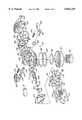
- FIG. 6is an exploded perspective view showing the components which make up the wand assembly
- FIG. 7is an exploded perspective of the valve in the wand head
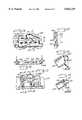
- FIG. 8is a plan view of the front valve body from the inlet side
- FIG. 9is a section taken along line 9--9 of FIG. 8;
- FIG. 10is a section taken along line 10--10 of FIG. 8;
- FIG. 11is an underside view of the main valve body shown in relation to FIG. 5;
- FIG. 12is a section taken along line 12--12 of FIG. 11;
- FIG. 13is a section taken along line 13--13 of FIG. 12;
- FIG. 14is a plan view of the intermediate body from the inlet side
- FIG. 15is a section along line 15--15 of FIG. 14;
- FIG. 16is a section along line 16--16 of FIG. 14;
- FIG. 17is a plan view of the rear body from the inlet side
- FIG. 18is a section along line 18--18 of FIG. 17 showing the unfiltered water inlet
- FIG. 19is a section along line 19--19 of FIG. 17 showing the filtered water inlet
- FIG. 20is an end view of the filter button
- FIG. 21is a section along line 21--21 of FIG. 20;
- FIG. 22is a side view of the filter actuator
- FIG. 23is an end view of FIG. 22 from the inlet side
- FIG. 24is a section along line 24--24 of FIG. 22;
- FIG. 25is an inlet side perspective of the filter actuator
- FIG. 26is an exploded sectional side view showing the method of connection between the filter button and the stem of the filter actuator
- FIG. 27is a plan view of the front gasket
- FIG. 28is a side view of the stream actuator
- FIG. 29is an inside end view of the stream actuator
- FIG. 30is a section along line 30--30 of FIG. 29;
- FIG. 31is an inside perspective view of the stream actuator
- FIG. 32is an outside end view of the spray actuator
- FIG. 33is a partial section taken along line 33--33 of FIG. 32;
- FIG. 34is a side view of the spray actuator
- FIG. 35is an inside perspective of the spray actuator
- FIG. 36is a plan view of the diaphragm
- FIG. 37is a section taken along line 37--37 of FIG. 36;
- FIG. 38is a plan view of the rear gasket
- FIG. 39is an end view of the spray former as viewed from the outlet side;
- FIG. 40is an inside end view of the spray former
- FIG. 41is an enlarged detail of FIG. 40
- FIG. 42is a section taken along line 42--42 of FIG. 40;
- FIG. 43is a top perspective view of the PCB assembly
- FIG. 44is a side view of FIG. 43;
- FIG. 45is a top plan view
- FIG. 46is a bottom plan view
- FIG. 47is an underside perspective of the PCB assembly
- FIG. 48is a perspective view of the filter I.D. keypad
- FIG. 49is a section along line 49--49 of FIG. 48;
- FIG. 50is an underside plan view of the wand body top
- FIG. 51is a sectional view taken on line 51--51 of FIG. 50;
- FIG. 52is an inside plan view of the wand body bottom
- FIG. 53is a sectional view taken along line 53--53 of FIG. 52;
- FIG. 54is an exploded sectional view of the wand housings
- FIG. 55is a sectional detail of the inlet end of the wand assembly
- FIG. 56is an end view of the quarter turn connector with integral check valves
- FIG. 57is a section taken along line 57--57 of FIG. 56;
- FIG. 58is an end view of the quarter turn connector with the check valves omitted as viewed from the right side of FIG. 57;
- FIG. 59is a perspective view of the anti-flow spool of one of the check valves.
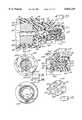
- FIG. 60is a plan of the filter assembly
- FIG. 61is a sectional view of the filter assembly taken along line 61--61 of FIG. 60;
- FIG. 62is a sectional view taken along line 62--62 of FIG. 61;
- FIG. 63is a sectional view of the filter jacket
- FIG. 64is an enlarged detail of the filter jacket end
- FIG. 65is an end view of the filter jacket
- FIG. 66is an enlarged sectional detail showing the attachment of the filter jacket cap
- FIG. 67is an end view of the filter jacket cap
- FIG. 68is a sectional view taken along line 68--68 of FIG. 67;
- FIG. 69is a plan view of the filter carbon end cap
- FIG. 70is a sectional view taken along line 70--70 of FIG. 69;
- FIG. 71is a side view of the quarter turn connector
- FIG. 72is a sectional view taken along line 72--72 of FIG. 71;
- FIG. 73is a perspective view of the filter carbon block as viewed from the exit end;
- FIG. 74is a perspective view of the filter carbon block as viewed from the inlet end
- FIG. 75is an end view of FIG. 73;
- FIG. 76is a section along line 76--76 of FIG. 75;
- FIG. 77is a section along line 77--77 of FIG. 76;
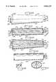
- FIG. 78is a top perspective of the boot assembly
- FIG. 79is a top plan view
- FIG. 80is a section along line 80--80 of FIG. 79;
- FIG. 81is a section along line 81--81 of FIG. 79;
- FIG. 82is an underside perspective of FIG. 78;
- FIG. 83is a block diagram of the wand assembly electronics.
- FIG. 84is a plan view of the liquid crystal display.
- the present inventionrelates to a faucet assembly primarily for use in a kitchen environment. It includes a wand, attached by a hose to a faucet control valve which may be either a single lever mixing valve or a two-handle control valve system.
- the wandmay be pulled out from the faucet housing, along with its hose connection, so that it may be directed by the user to various portions of the sink area.
- the wandprovides a stream discharge, a spray discharge, and a filtered water discharge.
- the dischargeWhen the water is initially turned on, the discharge will be in a stream form.
- the userpresses a spray button.
- the usermay either turn off the water or press the stream button.
- the filter buttonTo provide a filtered water discharge, the user presses the filter button, adjacent the nose of the wand and there will be a filtered water discharge.
- the faucetis returned from a filtered water discharge to a stream discharge by turning off the water.
- a button or control elementonce a button or control element is pressed, it may be released and will remain in the designated position.
- FIG. 1the faucet is shown using a single lever mixing valve cartridge.
- the wand assemblyis indicated at 10 and the faucet handle is indicated at 12.
- the faucet handle 12 and mixing valve 18form no specific part of the present invention and are only a means to provide water to the input of the wand assembly.
- the wateris mixed in that it has varying proportions of hot and cold water, as determined by the position of the control handle 12.
- the wand assemblyhas certain basic parts, each of which will be described in detail hereinafter.
- the wand assemblyincludes a wand body top 20, a wand body bottom 80, an upper cover 140 and a lower cover 180.
- a printed circuit board assembly (PCB assembly) 200Positioned within the housing assembly made up of the above-described elements is a printed circuit board assembly (PCB assembly) 200 and a wand control valve 400.
- the input for the wand assemblyis provided by a check valve assembly 300.
- the above-described partswhen assembled as described hereinafter, provide the three types of water discharge as determined by the positions of the control buttons.
- the check valve assembly 300is illustrated in FIGS. 55 through 59, 71 and 72.
- the check valve assembly 300provides the connection between the hose 19 and the wand assembly 10 and includes an outer connector 302 having exterior threads 304 for making the hose connection.
- a central passage 310which is the water passage through the connector assembly to the wand assembly.
- an antiflow spool 312illustrated particularly in FIG. 59.
- the spool 312has a conical seat 314 and a plurality of radially extending guide ribs or fins 316. The space between the ribs 316 provides for water flow and the ribs provide a guiding function to maintain proper orientation of the antiflow spool within the passage 310.
- the antiflow spool 312has an interior cavity 318 within which is positioned a spring 320.
- the spring 320is seated on a boss 322 and is effective to urge the antiflow spool 312 and an antisiphon spool 324 in opposite axial directions.
- the spool 312will normally have its conical seat 314 in peripheral contact with a seat 326 on the interior of passage 310 to close off the flow of water into the wand assembly. Insertion of the filter cartridge, as described hereinafter, will move the antiflow spool 312 off of the seat 326 to allow water flow.
- the spring 320normally closes the antisiphon spool 324 to prevent back siphonage.
- the antisiphon spool 324is opened by water flow as it comes from the hose connection.
- the antisiphon spool 324has an O-ring seal 336 positioned within a groove adjacent an outwardly extending flange 338. There is an axially extending projection 340 which houses the spring 320 and is positioned within the cavity 318 of the antiflow spool 312.
- the spool 324has a truncated conical nose 328 which seats against a conical surface 330 on a retainer 332.
- An O-ring 334seals the retainer to the interior of the passage 310 as formed by the connector 302.
- the wand body top 20is illustrated in FIGS. 50 and 51 and the wand body bottom 80 is illustrated in FIGS. 52 and 53.
- FIG. 54illustrates the wand body top and bottom from an end view in a slightly separated position.
- the wand body top 20has a partially frustoconic outer cover 22 and a partial cylindrical projection 24 which forms a part of the inlet connection with the check valve assembly.
- the interior of projection 24has a circumferential rib 26 which will bear against the interior wall 305 of cavity 306 when the wand bodies are attached to the check valve assembly as shown in FIG. 55. Rib 26 provides orientation to insure proper connection with the check valve assembly.
- Wand body top 20further includes a support 28 which will mount the PCB assembly 200, as will be described hereinafter.
- the wand body top 20has four spaced lugs or projections 30 which will interact with mating recesses 82 formed in an opposing edge of the cover 84 of wand body bottom 80.
- the wand body bottomhas a cylindrical projection 86 similar to the projection 24 on the wand body top, which projections together define the cylindrical connection with the check valve.
- the wand body bottomfurther has a weep opening 88 at the inlet end to permit seepage of any water which may accumulate within the wand assembly.
- the connection between the two wand bodiesincludes what is known as a half lap joint.
- the wand body top 20 along the edge which mates with the wand body bottomhas a continuous interior flange 31 and an adjacent rabbeted groove 32.
- the mating edge of the wand body bottomhas an interior projection 90 and a rabbeted groove 92.
- the wand bodiesare held together at the inlet side by the exterior cams 33 and 93 located on projections 24 and 86 which form a bayonet connection with the check valve assembly 300.
- the cam elements 33 and 93will interact with the openings 308 in the connector 302 once the wand body and check valve assembly have been axially moved to the position of FIG. 55, after which the check valve assembly is given a quarter turn so that the cams will interact in the manner shown in FIG. 55.
- the exterior of the wand assemblyis completed by the upper cover 140 and the lower cover 180.
- the upper coverincludes a visual display opening 142, which will be described in more detail and is shown specifically in FIG. 84.
- the upper cover 140further has a front recess 144 and there is a similar recess 182 in the lower cover, with the recesses, when combined in the assembled position, providing an opening for the filtered water discharge button.
- each of the upper and lower covershas recesses 146 and 184, respectively, for the spray and stream buttons to be described later.
- the filter assemblyis illustrated in FIGS. 60, 61 and 62, the filter jacket is illustrated in FIGS. 63 through 70, and the filter is illustrated in FIGS. 73 through 77.
- the filterwill consist of carbon granules, a binder and a lead scavenger. Acceptable proportions of these elements would include approximately 10-14 grams of a lead scavenger which may be a product called ATS manufactured by Engelhard Corporation, 20 grams of a binder which may be polyethylene, and approximately 30 grams of carbon particles.
- the carbon particlesshould be of a size which would pass through an 80 ⁇ 325 mesh screen, although the invention should not be so limited. It is desirable that the carbon block filter remove any particle greater than one micron which will eliminate certain potentially medically harmful microorganisms.
- the one micron sizeis a nominal rating for the filter.
- the filteris indicated at 362 and as shown in FIGS. 73 through 77, has a generally frustoconic exterior. There is an interior passage 364 which is somewhat tapered, gradually enlarging from the inlet end 366 to the outlet end 367. Positioned within the passage 364, as particularly shown in FIGS. 60 through 62, is a tube 368 which provides a direct unfiltered water connection from the inlet end of the filter assembly 360 to the outlet end.
- the inlet end of the filterincludes an end cap 370, shown in FIGS. 69 and 70, having an interior opening 372 which centers the tube 368 at the inlet end of the filter.
- a filter jacket cap 374illustrated in FIGS. 67 and 68, which may be ultrasonically welded to filter jacket 386.
- the center port 376has two filter identification projections 378 adjacent thereto, the purpose of which will be described in connection with the electronic system for the wand.
- a filtered water outlet port 380Directly adjacent to port 376 is a filtered water outlet port 380.
- the tube 368extends into the opening 382 of the cap which leads to the port 376 with the filtered water port 380 being in communication with the area extending about the unfiltered water tube 368.
- FIGS. 61 and 62there is a thin peripheral chamber 384 between the exterior of the carbon block filter 362 and the interior of the filter jacket 386.
- Watermay flow into the chamber 384 through a plurality of grooves 388 at the inlet end of the filter jacket as particularly shown in FIGS. 62 and 63.
- water flowing into the inlet port 390, from the check valve assembly 300will flow both into the tube 368 and into the peripheral chamber 384.
- Water flowing into the peripheral chambermust radially flow through the carbon block filter in order to reach the tapered annular space 392 which is inside of the filter and on the exterior of tube 368.
- filtered watercan then flow to the filtered water discharge port 380.
- the projection 394 of the filter jacket 386has an O-ring seal 396 and a pair of spaced projections 398, as particularly shown in FIGS. 61 and 62.
- These projectionsare effective to move the antiflow spool 312 away from its seat 326 to permit water to flow into the filter assembly.
- the projections on the filter assemblyare required in order to open the antiflow spool. Accordingly, the projections provide a safety feature, as when a filter is being changed, no water will flow into the wand.
- the wand control valve assemblywill be described in connection with FIGS. 7 through 19.
- the control valve assemblyincludes a rear body 402 shown in FIGS. 17, 18 and 19; an intermediate body 404, separated by a gasket 406 from rear body 402 and illustrated in FIGS. 14 through 18; a main valve body 408 separated by a gasket/diaphragm 400 from the intermediate body 404 and illustrated in FIGS. 11, 12 and 13; and a front body 412 separated by a gasket 413 from main body 408 illustrated in FIGS. 8 through 10.
- the rear body 402has a filtered water input 414 which includes a flow control element 416 and is connected to a filtered output port 418. This is shown in FIG. 19. Input 414 will connect with filtered water output 380 (FIG. 67). The unfiltered water from filter assembly output 376 flows into an inlet port 420 and cut through an outlet port 422. This is water for either the spray or stream discharge.
- the intermediate valve body 404 shown in FIGS. 14, 15 and 16has a filtered water passage 424 which receives water from rear body outlet 418 and passes the filtered water directly to the main body. Unfiltered water from the rear body flows into a passage 426 in the intermediate valve body 404, note FIG. 16, and then flows into a main body passage 428 shown in FIG. 13. The unfiltered water passes through the main body 408 and makes a 90 degree bend to flow into a cavity 430 at the front or outlet side of the main body. The unfiltered water then turns 90° again and flows through a cavity 432, which would normally be filled with the spool from the spray control button, with water exiting from cavity 432 through small passages 434, as shown particularly in FIG. 12.
- the wandhas both a spray discharge and a stream discharge, with the spray and stream discharge buttons being illustrated in FIGS. 28 through 34 and shown in their relationship to the above-described valve bodies in FIG. 7.
- the stream actuator shown in FIGS. 28 through 31includes a spool portion 460 which is located within cavity 442 shown in FIG. 13 and an exterior button portion 462.
- the button portion 462has a cylindrical cavity 464 which contains the return spring 466 shown in FIG. 7. Operation of the stream button will return the wand to a stream discharge if the wand is in the spray discharge.
- the spring 466normally retains the stream actuator in an outward position. The stream actuator forces water to flow through the stream flow path and shuts off flow through the spray flow path.
- the spray actuator illustrated in FIGS. 33-35is similar and has a spool 467 which is positioned within cavity 432 in FIG. 13. There is an exterior button 468 and a cavity 470 for location of a return spring 472. Both the spray actuator and the stream actuator have seal rings 474 and 478 for appropriate sealing of the cavities to prevent water from within the wand leaking to the outside. Seal ring 476 on the spray actuator prevents incoming unfiltered water from leaking prematurely into cavity 432.
- the diaphragm 410is important in having the wand assembly return to a stream position when the water is turned off or what may be termed a default position.
- the diaphragm 410is illustrated in FIGS. 4, 5, 7, 36 and 37. It has a central portion 480 which is located within cavity 482 in the main body as shown in FIGS. 4, 5 and 13.
- water flowing through passages 434will create a force on the diaphragm which will cause the diaphragm to remain against the intermediate body passage 448. Because of the differential forces on the diaphragm, it will remain in this position until the spray button is operated.
- the aerator for the stream dischargeis indicated at 482
- the spray former for the spray dischargeis indicated at 484, and is shown in particular in FIGS. 39 through 42.
- the spray formeris cylindrical in nature with a flange 492 at one end and a series of peripherally arranged spray forming discharge ports 494 at the opposite end.
- the stream dischargewill go through the center 496 of the spray former.
- the spray formerhas an annular cavity 498 which is in communication with the openings 494 and which will be in communication with the spray outlets 454 shown in FIG. 11.
- the diaphragm 410in addition to the movable central portion 480, has a series of openings which are in alignment with the above-described ports in the main body 408 and the intermediate body 404.
- the diaphragm portion 480is inherently biased toward a position in which water flows to a stream discharge. Force created by water pressure will move the diaphragm 480 to a position causing water to flow in the above-described spray path, assuming the spray actuator button has been depressed. Once a button has been depressed to cause either et stream or a spray discharge, release of the button will retain the wand in the particular discharge position caused by operation of the button.
- the front body 412contains the filtered water discharge. Filtered water will enter the front body 412 through a port 500; pass along passage 502, make a 90 degree turn to passage 504, make a further 90 degree turn into passage 506 and then down through the filtered water discharge port 508. This is assuming that the filtered water discharge button has been operated.
- the filtered water actuatoris shown in FIGS. 20 through 26.
- the filter actuator 510has an unfiltered flow preventing portion 512 which cooperates with a face seal 514 to fit within front cavity 430 in the main body 408. Normally, water will flow through cavity 430 in passing to the stream or spray discharge. Although filtered water will flow through the main body outwardly through port 518 (FIG. 13) to the front body to reach passage 500, the presence of the filter actuator 510 within cavity 506 (FIGS. 4, 5) in the front body will prevent a filter water discharge.
- the filter actuator 510has a filter button 520 with a cavity 522 to receive the end 524 of the filter actuator as particularly shown in FIG. 26. Movement of the button 520 will cause movement of the filter actuator to cause the blocking portion 512 and its related seal ring 514 to move into the cavity 430, preventing the flow of unfiltered water to the stream or spray discharge.
- the filter discharge actuator assemblyincludes the described button 520 and the front body 412, as well as the actuator 510.
- a spring 530fits within a cavity 532 in the button 520 and normally urges the button to the outward position shown in FIGS. 4 and 5.
- the springis supported on a portion of the front body indicated at 534. Screws 536 will pass through openings 538 in the front body, main body and intermediate body and screw into the rear body, as particularly shown in FIG. 7.
- the filter actuator 510mounts four separate seals, as shown in FIGS. 4, 5 and 7, the seals being indicated at 514, 540, 542 and 546. Further, the actuator has a seal 542 which bears against a seat 550 in the front body interior, as shown in FIGS. 4 and 5, which normally closes the flow of filtered water through the front body. Only when the button 520 is operated, causing the filter actuator 510 to move away from the described seat, will water flow into passage 506 and then down through the filter discharge 508.
- the filter actuatorwill close off the flow of unfiltered stream and spray water through cavity 430 and that pressure applied to the front of unfiltered flow portion 512 will hold the filter actuator in the described position until water is turned off.
- spring 530will return the filter button and filter actuator to their normally closed position, as shown in FIGS. 4 and 5, permitting unfiltered water to flow in the previously described passage.
- the wand control valves assemblywill return to the default stream position when water is turned off and this is the only way that the filter button can be returned to its at rest or default position shown in FIGS. 4 and 5.
- the PCB assembly 200will normally seat upon the top wand housing projection 28, with the PCB assembly being illustrated in detail in FIGS. 43 through 46.
- the circuit components which are shown physically on the PCB assembly 200are illustrated in FIG. 83.
- FIGS. 78 through 82illustrate a gasket 202 which fits over the PCB assembly 200 and has, molded integrally therewith, a stream boot 204 and a spray boot 206, as well as a filter water discharge boot 208.
- the boot, a single molded elastomeric seal element,will be positioned as shown in FIGS.
- the seal elementcomprises the visible exterior buttons for the user to operate with depression thereof, causing the buttons to move through the described operating positions.
- the circuit associated with the filter discharge which is mounted on PCB assembly 200includes a microcontroller 210 which has combined hardware and software to provide the following described functions.
- a lithium cell 212which provides the battery power for the microcontroller.
- a quartz crystal 214which is a timing device and provides uniform clock pulses to the microcontroller whenever there is a filtered water discharge.
- the microcontrolleris connected to a liquid crystal display 216 which is shown in FIG. 84 with the various icons that will be displayed.
- the circuit of FIG. 83further includes a piezo diaphragm 228 connected to a driver circuit 230 which will provide an audio indication to the user to correspond with certain visual displays.
- filter lifeis shown by the percentage at the top of the display indicated at 218, in this case the display being 100 percent.
- Beneath the display of the actual percentageis a representation of a water drop indicated at 220, with a series of wavy lines thereacross, with the lines moving during the time there is a discharge of filtered water.
- a low water symbol 224which will flash when filter life remaining is less than five percent. An audio indication will accompany this display.
- a low battery indicator 226which will flash when the remaining life of the lithium cell 212 has reached an unacceptable level, indicating replacement is desirable. Again, this will be accompanied with an audio indication.
- the low filter life icon 224 and battery indicatorwill appear both when the filter is active and when it is inactive.
- the circuitfurther includes filter cable selection jumpers indicated at 232 which are to accommodate the use of the wand with filters having different capacities. Thus, for a particular filter or for filters of a particular type the jumpers would be set in one position, whereas, if different life filters are used, the jumpers might be varied and their use is just to accommodate future variations in filter life.
- There is a filter activation switch 234which is operated upon actuation of the filter button through a magnet 236 shown in FIG. 7. Closure of switch 234 causes pulses from timer 214 to be used by the microcontroller to determining remaining filter life.
- filter identification switches 238which are responsive to the filter identification protrusions to be described hereinafter.
- Each filterwill have a designated life and although all of the filters will be of the same physical size, the makeup of the carbon particles and related elements in the filter will provide filters with different capacity or different ratings.
- the identification of the particular filteris necessary so that the microcontroller can properly display the remaining life of the filter.
- the clock pulses from timer 214provide the microcontroller with an indication of filter use, which with the known capacity of a particular filter provides the data for the microcontroller to calculate remaining filter life and provide a signal indicative thereof to the liquid crystal display 216.
- the filter identification protrusionsare indicated at 378 in FIG. 67. When the filter is installed, these protrusions will be in contact with the filter I.D. keypad indicated at 250 in FIGS. 48 and 49.
- the keypadis a silicon rubber element which is responsive to the particular protrusions on the filter cartridge and in turn will cause the contacts 252 and 254 of the keypad to be pushed into electrical and mechanical contact with the filter identification switch elements 238 on the printed circuit board.
- the filter I.D. keypadhas a pressure sensitive adhesive backing so that this element can also function as a seal to prevent water from entering the electronic compartment.
- the spray buttonis pressed, which causes movement of the spray actuator so that water will then flow through the above-described spray path rather than the stream path.
- the buttonOnce the button has been depressed, it may be released and water will continue to flow in a spray pattern, as the diaphragm will have moved to a spray position and the pressure differential will retain it in such position.
- the stream buttonis pressed, causing movement of the stream actuator, in which case the diaphragm will move closing off the flow of water to the spray pathway. Again, a momentary depression of the button will cause the wand to return to the stream position.
- the filter buttonWhen it is desired to have a filter discharge, the filter button is depressed, which will close off the flow of water in the stream and spray path and will open the path for filtered water to flow to the filtered water discharge. This discharge will continue until such time as water is turned off, as that is the only way to return the wand to its default stream position.
- the readout which is powered by the described lithium batterywill give visual indication to the user whenever the wand is in a filter position of the remaining life of the filter. This will be a percentage indication and will be accompanied by a visual movement of the wavy lines in the water drop icon when the filter is being used. At such time as the filter life reaches a five percent level, there will be both a flashing visual and an audio warning. This will occur both when the filter button is activated and deactivated. If battery life reaches an unacceptable level, there will also be an audio and flashing visual display when the filter is active and inactive.
- the filter displayprovides an indication of the remaining life of the filter, when the filter is completely used up, as well as when the battery should be changed.
Landscapes
- Engineering & Computer Science (AREA)
- Water Supply & Treatment (AREA)
- Health & Medical Sciences (AREA)
- Life Sciences & Earth Sciences (AREA)
- Hydrology & Water Resources (AREA)
- Public Health (AREA)
- Chemical & Material Sciences (AREA)
- Chemical Kinetics & Catalysis (AREA)
- Domestic Plumbing Installations (AREA)
- Multiple-Way Valves (AREA)
Abstract
Description
Claims (35)
Priority Applications (3)
| Application Number | Priority Date | Filing Date | Title |
|---|---|---|---|
| US08/761,404US5823229A (en) | 1996-12-06 | 1996-12-06 | Faucet having multiple water discharges |
| CA002221645ACA2221645C (en) | 1996-12-06 | 1997-11-20 | Faucet having multiple water discharges |
| MXPA/A/1997/009922AMXPA97009922A (en) | 1996-12-06 | 1997-12-05 | Tap with multiple downloads from a |
Applications Claiming Priority (1)
| Application Number | Priority Date | Filing Date | Title |
|---|---|---|---|
| US08/761,404US5823229A (en) | 1996-12-06 | 1996-12-06 | Faucet having multiple water discharges |
Publications (1)
| Publication Number | Publication Date |
|---|---|
| US5823229Atrue US5823229A (en) | 1998-10-20 |
Family
ID=25062074
Family Applications (1)
| Application Number | Title | Priority Date | Filing Date |
|---|---|---|---|
| US08/761,404Expired - Fee RelatedUS5823229A (en) | 1996-12-06 | 1996-12-06 | Faucet having multiple water discharges |
Country Status (2)
| Country | Link |
|---|---|
| US (1) | US5823229A (en) |
| CA (1) | CA2221645C (en) |
Cited By (76)
| Publication number | Priority date | Publication date | Assignee | Title |
|---|---|---|---|---|
| US5935426A (en) | 1997-08-08 | 1999-08-10 | Teledyne Industries, Inc., A California Corporation | Water treatment device with volumetric and time monitoring features |
| US5993648A (en)* | 1998-03-17 | 1999-11-30 | American Standard, Inc. | Water filtration device with a water fountain outlet and a faucet outlet with flow viewing apparatus |
| US6051144A (en)* | 1997-03-19 | 2000-04-18 | Clack Corporation | Liquid filtration system and replaceable filter cartridge usable therewith |
| US6074552A (en)* | 1998-04-24 | 2000-06-13 | Trumeter Company Ltd. | Electrical switch |
| US6145670A (en)* | 1997-09-22 | 2000-11-14 | Risser; William | Bathtub spout with removable filter |
| US6179130B1 (en)* | 1997-08-08 | 2001-01-30 | Emhart Inc. | Faucet spout assembly |
| US6231770B1 (en)* | 1996-07-09 | 2001-05-15 | Pall Corporation | Multiple element filter and method of using therefor |
| US6533926B2 (en)* | 2001-04-05 | 2003-03-18 | Fleetguard, Inc. | Filter cartridge with concentric circuit rings for data transmission |
| US6537444B2 (en)* | 2001-04-05 | 2003-03-25 | Fleetguard, Inc. | Replaceable-cartridge filter with data transmission feature |
| US20030132306A1 (en)* | 2002-01-15 | 2003-07-17 | Chiu Edward Samson | Mixing faucet having multiple discharges |
| US6599428B1 (en) | 1999-10-01 | 2003-07-29 | Paragon Water Systems, Inc. | Filter system for removing contaminants from water and method thereof |
| US6619567B1 (en)* | 2002-07-15 | 2003-09-16 | Globe Union Industrial Corp. | Structure of a flexible water tap |
| US20040164183A1 (en)* | 2001-06-04 | 2004-08-26 | Fabrizio Nobili | Water dispensing head for a handshower |
| US20040182457A1 (en)* | 2003-03-20 | 2004-09-23 | Freddy Vidal | Fluid spigot and filter unit |
| US6797156B2 (en)* | 2001-12-21 | 2004-09-28 | Yiu Chau Chau | Faucet water treatment |
| US20050072722A1 (en)* | 1999-07-05 | 2005-04-07 | Kotobuki Tsushou Co., Ltd. | Shower head with water purification function |
| US20050145554A1 (en)* | 1999-10-01 | 2005-07-07 | Cunningham William G. | Multiple flow sink counter-top water sprayer and filter system |
| EP1557501A1 (en) | 2004-01-26 | 2005-07-27 | Fabrizio Nobili | Treated water delivery assembly, faucet and feeding pipe therefor |
| US20050224406A1 (en)* | 1999-07-05 | 2005-10-13 | Kotobuki Tsushou Co., Ltd. | Shower head with water purification function |
| US20060016912A1 (en)* | 2004-07-21 | 2006-01-26 | Fabrizio Nobili | Spray head for sprayers in general and particularly for manual sprayers for sinks and the like |
| US20060102549A1 (en)* | 2004-11-18 | 2006-05-18 | Arvinmeritor Technology, Llc | Co-molded and cured filter cartridge end using different durometer plastisols |
| USD533622S1 (en) | 2003-10-01 | 2006-12-12 | Water Pik, Inc. | End-of-faucet filter |
| US20070018019A1 (en)* | 2005-07-21 | 2007-01-25 | Fabrizio Nobili | Spray head for differential delivery of treated water and mains water |
| US20070119773A1 (en)* | 2005-11-30 | 2007-05-31 | Ratnakar Sahasrabudhe | Water filtration system |
| USD545394S1 (en) | 2005-11-30 | 2007-06-26 | General Electric Company | Water treatment assembly |
| GB2433890A (en)* | 2004-10-09 | 2007-07-11 | Enviroquest Group Ltd | Non-ionic surfactant aggregates |
| USD547417S1 (en) | 2005-11-30 | 2007-07-24 | General Electric Company | Water treatment assembly |
| US7261117B2 (en) | 2003-10-17 | 2007-08-28 | Access Business Group International Llc | Diverter valve assembly |
| US20070200014A1 (en)* | 2006-02-28 | 2007-08-30 | Fabrizio Nobili | Sink spray head with supply jet variation and flow rate regulation |
| US20070210181A1 (en)* | 2006-02-28 | 2007-09-13 | Fabrizio Nobili | Sink spray head with supply jet variation and flow rate regulation |
| US20070221760A1 (en)* | 2006-03-21 | 2007-09-27 | Fabrizio Nobili | Spray head with simplified activation particularly for kitchen sinks |
| USD555763S1 (en) | 2005-04-25 | 2007-11-20 | Fabrizio Nobili | Shower head |
| USD555768S1 (en) | 2005-04-25 | 2007-11-20 | Fabrizio Nobili | Shower head |
| US20080006707A1 (en)* | 2006-07-06 | 2008-01-10 | Fabrizio Nobili | Showerhead with simplified actuator |
| US7326334B2 (en) | 2003-10-01 | 2008-02-05 | Instapure Brands, Inc. | End-of-faucet filter |
| US7343930B2 (en) | 2004-12-03 | 2008-03-18 | Masco Corporation Of Indiana | Sprayer with non-faucet control |
| USD576255S1 (en) | 2006-07-06 | 2008-09-02 | Fabrizio Nobili | Faucet |
| US20080245897A1 (en)* | 2006-08-03 | 2008-10-09 | Fabrizio Nobili | Showerhead |
| USD585961S1 (en) | 2007-07-27 | 2009-02-03 | Fabrizio Nobili | Showerhead |
| USD587343S1 (en) | 2007-07-27 | 2009-02-24 | Fabrizio Nobili | Showerhead |
| USD598979S1 (en) | 2006-11-02 | 2009-08-25 | Fabrizio Nobili | Faucet |
| US20090211654A1 (en)* | 2005-07-01 | 2009-08-27 | Fabrizio Nobili | Assembly For The Differential Delivery Of Treated And Mains Water |
| US20100000931A1 (en)* | 2008-07-01 | 2010-01-07 | Janet Castillo | Potable liquid dispenser |
| US20100089472A1 (en)* | 2007-10-31 | 2010-04-15 | Meza Humberto V | Faucet with Integral Filter and Method of Installation |
| US7850098B2 (en) | 2005-05-13 | 2010-12-14 | Masco Corporation Of Indiana | Power sprayer |
| US7871020B2 (en) | 2006-01-26 | 2011-01-18 | Masco Corporation Of Indiana | Faucet spray head with volume control |
| US20110114187A1 (en)* | 2009-11-19 | 2011-05-19 | Masco Corporation Of Indiana | System and method for conveying status information regarding an electronic faucet |
| US8089473B2 (en) | 2006-04-20 | 2012-01-03 | Masco Corporation Of Indiana | Touch sensor |
| US8118240B2 (en) | 2006-04-20 | 2012-02-21 | Masco Corporation Of Indiana | Pull-out wand |
| US8152078B2 (en) | 2006-10-25 | 2012-04-10 | Masco Corporation Of Indiana | Faucet spray head |
| WO2012045276A1 (en)* | 2010-10-09 | 2012-04-12 | 厦门松霖科技有限公司 | Button-switching water outlet mechanism and switching method thereof |
| US8162236B2 (en)* | 2006-04-20 | 2012-04-24 | Masco Corporation Of Indiana | Electronic user interface for electronic mixing of water for residential faucets |
| ITVR20100225A1 (en)* | 2010-11-25 | 2012-05-26 | Scilm Spa | DEVICE FOR WATER PURIFICATION. |
| US8365767B2 (en) | 2006-04-20 | 2013-02-05 | Masco Corporation Of Indiana | User interface for a faucet |
| US8424781B2 (en) | 2006-02-06 | 2013-04-23 | Masco Corporation Of Indiana | Power sprayer |
| WO2013019272A3 (en)* | 2011-07-31 | 2013-05-23 | Sloan Valve Company | Automatic faucets |
| US8448667B2 (en) | 2009-10-19 | 2013-05-28 | Masco Corporation Of Indiana | Multi-function pull-out wand |
| CN103566651A (en)* | 2012-08-11 | 2014-02-12 | 宁波康润机械科技有限公司 | Filter for spraying box |
| US20150076254A1 (en)* | 2013-09-18 | 2015-03-19 | David Aaron Farley | Filtered shower wand with twist-lock connector |
| US9175458B2 (en) | 2012-04-20 | 2015-11-03 | Delta Faucet Company | Faucet including a pullout wand with a capacitive sensing |
| US9243756B2 (en) | 2006-04-20 | 2016-01-26 | Delta Faucet Company | Capacitive user interface for a faucet and method of forming |
| US20160090721A1 (en)* | 2014-09-30 | 2016-03-31 | Xiamen Runner Industrial Corporation | Two-Route Switching Water Output System |
| US20160090720A1 (en)* | 2014-09-30 | 2016-03-31 | Xiamen Runner Industrial Corporation | Two-Path Water Output Device |
| US20160091100A1 (en)* | 2014-09-30 | 2016-03-31 | Xiamen Runner Industrial Corporation | Water Output Converter |
| US20160138250A1 (en)* | 2014-11-17 | 2016-05-19 | Xiamen Runner Industrial Corporation | Type Water Output Converter |
| CN105804166A (en)* | 2011-03-15 | 2016-07-27 | 仕龙阀门公司 | Automatic faucets |
| US20170121184A1 (en)* | 2015-10-28 | 2017-05-04 | Xiaomi Inc. | Method and apparatus for controlling water output of water purifier, water purifier, and storage medium |
| US9695579B2 (en) | 2011-03-15 | 2017-07-04 | Sloan Valve Company | Automatic faucets |
| JP2018172871A (en)* | 2017-03-31 | 2018-11-08 | 株式会社タカギ | Faucet fixture |
| CN111059328A (en)* | 2019-12-30 | 2020-04-24 | 宁波方太厨具有限公司 | Fireproof check valve for range hood |
| US11053670B2 (en) | 2018-08-23 | 2021-07-06 | Spectrum Brands, Inc. | Faucet spray head alignment system |
| US20220034074A1 (en)* | 2020-08-01 | 2022-02-03 | Vann Stone Faison | Duality Faucet Head |
| US11267003B2 (en) | 2005-05-13 | 2022-03-08 | Delta Faucet Company | Power sprayer |
| US11346088B2 (en) | 2018-08-23 | 2022-05-31 | Spectrum Brands, Inc. | Faucet head alignment system |
| US20240307896A1 (en)* | 2023-03-17 | 2024-09-19 | James K. Isabell | Shower Wand Scrubber |
| US12442164B2 (en) | 2023-11-20 | 2025-10-14 | Assa Abloy Americas Residential Inc. | Faucet spray head alignment system |
Families Citing this family (2)
| Publication number | Priority date | Publication date | Assignee | Title |
|---|---|---|---|---|
| US10525387B2 (en) | 2017-04-06 | 2020-01-07 | Whirlpool Corporation | Filter cartridge |
| US10584040B2 (en) | 2017-10-06 | 2020-03-10 | Whirlpool Corporation | Filter cartridge |
Citations (22)
| Publication number | Priority date | Publication date | Assignee | Title |
|---|---|---|---|---|
| US712868A (en)* | 1902-05-09 | 1902-11-04 | William A Traxton | Filtering-faucet. |
| US738486A (en)* | 1903-01-28 | 1903-09-08 | Lewis E Rogers | Filter. |
| US816517A (en)* | 1905-07-10 | 1906-03-27 | Augustus P Whalen | Combined faucet and filter. |
| US1835865A (en)* | 1930-03-06 | 1931-12-08 | Fred E Hansen | Nozzle |
| US2334791A (en)* | 1941-03-04 | 1943-11-23 | Abraham Rothenberg | Attachment filter |
| US3637083A (en)* | 1966-04-04 | 1972-01-25 | Nils O Rosaen | Fluid system with self-cleaning filter |
| US3690565A (en)* | 1971-01-07 | 1972-09-12 | Ecom Systems Inc | Diverter valve |
| US3722800A (en)* | 1969-05-28 | 1973-03-27 | Melard Mfg Corp | Shuttle type diverter valve for use with handle controlled spray |
| US3743188A (en)* | 1970-11-13 | 1973-07-03 | J Wagner | Spray gun |
| US3895643A (en)* | 1969-10-22 | 1975-07-22 | Modern Faucet Mfg Co | Valve assembly |
| US4107046A (en)* | 1975-09-29 | 1978-08-15 | Teledyne Industries, Inc. | Water purifier |
| US4242201A (en)* | 1979-06-14 | 1980-12-30 | TDV Co. | By-pass water softener system and installation |
| US4863103A (en)* | 1986-07-08 | 1989-09-05 | Gannaway Richard M | Combination sink spray and water filter apparatus |
| US4982900A (en)* | 1988-05-16 | 1991-01-08 | Blake William S | Trigger sprayer |
| US5008011A (en)* | 1989-10-20 | 1991-04-16 | Underwood David T | Shower dechlorinator using granulated copper alloy filter material |
| US5020569A (en)* | 1990-10-01 | 1991-06-04 | Wpm, Inc. | Vented faucet system |
| US5145093A (en)* | 1991-10-15 | 1992-09-08 | Zeller Henry O | Toothpaste dispenser |
| US5152464A (en)* | 1991-06-12 | 1992-10-06 | Farley Frederick A | Shower filter assembly |
| US5171429A (en)* | 1989-09-29 | 1992-12-15 | Inax Corporation | Apparatus for discharging water with passage selection sensor |
| US5279329A (en)* | 1992-11-16 | 1994-01-18 | Amway Corporation | Faucet diverter valve |
| US5370314A (en)* | 1992-09-28 | 1994-12-06 | J. Wagner Gmbh | Spray gun |
| US5385667A (en)* | 1991-06-04 | 1995-01-31 | Steger; William R. | Apparatus for the purification of shower water |
- 1996
- 1996-12-06USUS08/761,404patent/US5823229A/ennot_activeExpired - Fee Related
- 1997
- 1997-11-20CACA002221645Apatent/CA2221645C/ennot_activeExpired - Fee Related
Patent Citations (23)
| Publication number | Priority date | Publication date | Assignee | Title |
|---|---|---|---|---|
| US712868A (en)* | 1902-05-09 | 1902-11-04 | William A Traxton | Filtering-faucet. |
| US738486A (en)* | 1903-01-28 | 1903-09-08 | Lewis E Rogers | Filter. |
| US816517A (en)* | 1905-07-10 | 1906-03-27 | Augustus P Whalen | Combined faucet and filter. |
| US1835865A (en)* | 1930-03-06 | 1931-12-08 | Fred E Hansen | Nozzle |
| US2334791A (en)* | 1941-03-04 | 1943-11-23 | Abraham Rothenberg | Attachment filter |
| US3637083A (en)* | 1966-04-04 | 1972-01-25 | Nils O Rosaen | Fluid system with self-cleaning filter |
| US3722800A (en)* | 1969-05-28 | 1973-03-27 | Melard Mfg Corp | Shuttle type diverter valve for use with handle controlled spray |
| US3895643A (en)* | 1969-10-22 | 1975-07-22 | Modern Faucet Mfg Co | Valve assembly |
| US3743188A (en)* | 1970-11-13 | 1973-07-03 | J Wagner | Spray gun |
| US3690565A (en)* | 1971-01-07 | 1972-09-12 | Ecom Systems Inc | Diverter valve |
| US4107046A (en)* | 1975-09-29 | 1978-08-15 | Teledyne Industries, Inc. | Water purifier |
| US4242201A (en)* | 1979-06-14 | 1980-12-30 | TDV Co. | By-pass water softener system and installation |
| US4863103A (en)* | 1986-07-08 | 1989-09-05 | Gannaway Richard M | Combination sink spray and water filter apparatus |
| US4982900A (en)* | 1988-05-16 | 1991-01-08 | Blake William S | Trigger sprayer |
| US4982900B1 (en)* | 1988-05-16 | 1998-05-05 | William S Blake | Trigger sprayer |
| US5171429A (en)* | 1989-09-29 | 1992-12-15 | Inax Corporation | Apparatus for discharging water with passage selection sensor |
| US5008011A (en)* | 1989-10-20 | 1991-04-16 | Underwood David T | Shower dechlorinator using granulated copper alloy filter material |
| US5020569A (en)* | 1990-10-01 | 1991-06-04 | Wpm, Inc. | Vented faucet system |
| US5385667A (en)* | 1991-06-04 | 1995-01-31 | Steger; William R. | Apparatus for the purification of shower water |
| US5152464A (en)* | 1991-06-12 | 1992-10-06 | Farley Frederick A | Shower filter assembly |
| US5145093A (en)* | 1991-10-15 | 1992-09-08 | Zeller Henry O | Toothpaste dispenser |
| US5370314A (en)* | 1992-09-28 | 1994-12-06 | J. Wagner Gmbh | Spray gun |
| US5279329A (en)* | 1992-11-16 | 1994-01-18 | Amway Corporation | Faucet diverter valve |
Cited By (111)
| Publication number | Priority date | Publication date | Assignee | Title |
|---|---|---|---|---|
| US6231770B1 (en)* | 1996-07-09 | 2001-05-15 | Pall Corporation | Multiple element filter and method of using therefor |
| US6051144A (en)* | 1997-03-19 | 2000-04-18 | Clack Corporation | Liquid filtration system and replaceable filter cartridge usable therewith |
| US6284129B1 (en) | 1997-08-08 | 2001-09-04 | Water Pik, Inc. | Water treatment device with volumetric and time monitoring features |
| US6517707B2 (en) | 1997-08-08 | 2003-02-11 | Water Pik, Inc. | Water treatment device with volumetric and time monitoring features |
| US6106705A (en) | 1997-08-08 | 2000-08-22 | Teledyne Industries, Inc. | Water treatment device with volumetric and time monitoring features |
| US5935426A (en) | 1997-08-08 | 1999-08-10 | Teledyne Industries, Inc., A California Corporation | Water treatment device with volumetric and time monitoring features |
| US6179130B1 (en)* | 1997-08-08 | 2001-01-30 | Emhart Inc. | Faucet spout assembly |
| US6926821B2 (en) | 1997-08-08 | 2005-08-09 | Water Pik, Inc. | Water treatment device with volumetric and time monitoring features |
| US6145670A (en)* | 1997-09-22 | 2000-11-14 | Risser; William | Bathtub spout with removable filter |
| US5993648A (en)* | 1998-03-17 | 1999-11-30 | American Standard, Inc. | Water filtration device with a water fountain outlet and a faucet outlet with flow viewing apparatus |
| US6074552A (en)* | 1998-04-24 | 2000-06-13 | Trumeter Company Ltd. | Electrical switch |
| US20050072722A1 (en)* | 1999-07-05 | 2005-04-07 | Kotobuki Tsushou Co., Ltd. | Shower head with water purification function |
| US7504033B2 (en) | 1999-07-05 | 2009-03-17 | Kotobuki Tsushou Co., Ltd. | Water quality purification cartidge |
| US20050224406A1 (en)* | 1999-07-05 | 2005-10-13 | Kotobuki Tsushou Co., Ltd. | Shower head with water purification function |
| US7235176B1 (en) | 1999-07-05 | 2007-06-26 | Kotobuki Tsushou Co., Ltd. | Shower head with water purification function |
| US6599428B1 (en) | 1999-10-01 | 2003-07-29 | Paragon Water Systems, Inc. | Filter system for removing contaminants from water and method thereof |
| US20050145554A1 (en)* | 1999-10-01 | 2005-07-07 | Cunningham William G. | Multiple flow sink counter-top water sprayer and filter system |
| US6533926B2 (en)* | 2001-04-05 | 2003-03-18 | Fleetguard, Inc. | Filter cartridge with concentric circuit rings for data transmission |
| US6537444B2 (en)* | 2001-04-05 | 2003-03-25 | Fleetguard, Inc. | Replaceable-cartridge filter with data transmission feature |
| US20040164183A1 (en)* | 2001-06-04 | 2004-08-26 | Fabrizio Nobili | Water dispensing head for a handshower |
| US6797156B2 (en)* | 2001-12-21 | 2004-09-28 | Yiu Chau Chau | Faucet water treatment |
| US6808123B2 (en) | 2002-01-15 | 2004-10-26 | Edward Samson Chiu | Mixing faucet having multiple discharges |
| US20030132306A1 (en)* | 2002-01-15 | 2003-07-17 | Chiu Edward Samson | Mixing faucet having multiple discharges |
| US6619567B1 (en)* | 2002-07-15 | 2003-09-16 | Globe Union Industrial Corp. | Structure of a flexible water tap |
| US6941968B2 (en)* | 2003-03-20 | 2005-09-13 | Qmp, Inc. | Fluid spigot and filter unit |
| US20040182457A1 (en)* | 2003-03-20 | 2004-09-23 | Freddy Vidal | Fluid spigot and filter unit |
| US7326334B2 (en) | 2003-10-01 | 2008-02-05 | Instapure Brands, Inc. | End-of-faucet filter |
| USD533622S1 (en) | 2003-10-01 | 2006-12-12 | Water Pik, Inc. | End-of-faucet filter |
| US7261117B2 (en) | 2003-10-17 | 2007-08-28 | Access Business Group International Llc | Diverter valve assembly |
| US20050161533A1 (en)* | 2004-01-26 | 2005-07-28 | Fabrizio Nobili | Delivery system for treated water, showerhead and supply pipe for said system |
| EP1557501A1 (en) | 2004-01-26 | 2005-07-27 | Fabrizio Nobili | Treated water delivery assembly, faucet and feeding pipe therefor |
| US7314189B2 (en) | 2004-01-26 | 2008-01-01 | Fabrizio Nobili | Delivery system for treated water, showerhead and supply pipe for said system |
| US20060016912A1 (en)* | 2004-07-21 | 2006-01-26 | Fabrizio Nobili | Spray head for sprayers in general and particularly for manual sprayers for sinks and the like |
| GB2433890A (en)* | 2004-10-09 | 2007-07-11 | Enviroquest Group Ltd | Non-ionic surfactant aggregates |
| GB2433890B (en)* | 2004-10-09 | 2009-02-11 | Enviroquest Group Ltd | Non-ionic surfactant aggregates |
| US20060102549A1 (en)* | 2004-11-18 | 2006-05-18 | Arvinmeritor Technology, Llc | Co-molded and cured filter cartridge end using different durometer plastisols |
| US7343930B2 (en) | 2004-12-03 | 2008-03-18 | Masco Corporation Of Indiana | Sprayer with non-faucet control |
| USD562943S1 (en) | 2005-04-25 | 2008-02-26 | Fabrizio Nobili | Shower head |
| USD555763S1 (en) | 2005-04-25 | 2007-11-20 | Fabrizio Nobili | Shower head |
| USD555768S1 (en) | 2005-04-25 | 2007-11-20 | Fabrizio Nobili | Shower head |
| USD559946S1 (en) | 2005-04-25 | 2008-01-15 | Fabrizio Nobili | Shower head |
| USD560754S1 (en) | 2005-04-25 | 2008-01-29 | Fabrizio Nobili | Shower head |
| US7850098B2 (en) | 2005-05-13 | 2010-12-14 | Masco Corporation Of Indiana | Power sprayer |
| US11267003B2 (en) | 2005-05-13 | 2022-03-08 | Delta Faucet Company | Power sprayer |
| US10618066B2 (en) | 2005-05-13 | 2020-04-14 | Delta Faucet Company | Power sprayer |
| US9962718B2 (en) | 2005-05-13 | 2018-05-08 | Delta Faucet Company | Power sprayer |
| US20090211654A1 (en)* | 2005-07-01 | 2009-08-27 | Fabrizio Nobili | Assembly For The Differential Delivery Of Treated And Mains Water |
| US20070018019A1 (en)* | 2005-07-21 | 2007-01-25 | Fabrizio Nobili | Spray head for differential delivery of treated water and mains water |
| USD547417S1 (en) | 2005-11-30 | 2007-07-24 | General Electric Company | Water treatment assembly |
| US20070119773A1 (en)* | 2005-11-30 | 2007-05-31 | Ratnakar Sahasrabudhe | Water filtration system |
| USD545394S1 (en) | 2005-11-30 | 2007-06-26 | General Electric Company | Water treatment assembly |
| US8256625B2 (en) | 2005-11-30 | 2012-09-04 | General Electric Company | Water filtration system |
| US7871020B2 (en) | 2006-01-26 | 2011-01-18 | Masco Corporation Of Indiana | Faucet spray head with volume control |
| US8424781B2 (en) | 2006-02-06 | 2013-04-23 | Masco Corporation Of Indiana | Power sprayer |
| US20070210181A1 (en)* | 2006-02-28 | 2007-09-13 | Fabrizio Nobili | Sink spray head with supply jet variation and flow rate regulation |
| US20070200014A1 (en)* | 2006-02-28 | 2007-08-30 | Fabrizio Nobili | Sink spray head with supply jet variation and flow rate regulation |
| US7607588B2 (en)* | 2006-02-28 | 2009-10-27 | Fabrizio Nobili | Sink spray head with supply jet variation and flow rate regulation |
| US20070221760A1 (en)* | 2006-03-21 | 2007-09-27 | Fabrizio Nobili | Spray head with simplified activation particularly for kitchen sinks |
| US9856634B2 (en) | 2006-04-20 | 2018-01-02 | Delta Faucet Company | Fluid delivery device with an in-water capacitive sensor |
| US9715238B2 (en) | 2006-04-20 | 2017-07-25 | Delta Faucet Company | Electronic user interface for electronic mixing of water for residential faucets |
| US10698429B2 (en) | 2006-04-20 | 2020-06-30 | Delta Faucet Company | Electronic user interface for electronic mixing of water for residential faucets |
| US11886208B2 (en) | 2006-04-20 | 2024-01-30 | Delta Faucet Company | Electronic user interface for electronic mixing of water for residential faucets |
| US8089473B2 (en) | 2006-04-20 | 2012-01-03 | Masco Corporation Of Indiana | Touch sensor |
| US8118240B2 (en) | 2006-04-20 | 2012-02-21 | Masco Corporation Of Indiana | Pull-out wand |
| US9228329B2 (en) | 2006-04-20 | 2016-01-05 | Delta Faucet Company | Pull-out wand |
| US9285807B2 (en) | 2006-04-20 | 2016-03-15 | Delta Faucet Company | Electronic user interface for electronic mixing of water for residential faucets |
| US8162236B2 (en)* | 2006-04-20 | 2012-04-24 | Masco Corporation Of Indiana | Electronic user interface for electronic mixing of water for residential faucets |
| US9243756B2 (en) | 2006-04-20 | 2016-01-26 | Delta Faucet Company | Capacitive user interface for a faucet and method of forming |
| US8243040B2 (en) | 2006-04-20 | 2012-08-14 | Masco Corporation Of Indiana | Touch sensor |
| US8365767B2 (en) | 2006-04-20 | 2013-02-05 | Masco Corporation Of Indiana | User interface for a faucet |
| US20080006707A1 (en)* | 2006-07-06 | 2008-01-10 | Fabrizio Nobili | Showerhead with simplified actuator |
| USD576255S1 (en) | 2006-07-06 | 2008-09-02 | Fabrizio Nobili | Faucet |
| US20080245897A1 (en)* | 2006-08-03 | 2008-10-09 | Fabrizio Nobili | Showerhead |
| US8152078B2 (en) | 2006-10-25 | 2012-04-10 | Masco Corporation Of Indiana | Faucet spray head |
| USD598979S1 (en) | 2006-11-02 | 2009-08-25 | Fabrizio Nobili | Faucet |
| USD587343S1 (en) | 2007-07-27 | 2009-02-24 | Fabrizio Nobili | Showerhead |
| USD585961S1 (en) | 2007-07-27 | 2009-02-03 | Fabrizio Nobili | Showerhead |
| US20100089472A1 (en)* | 2007-10-31 | 2010-04-15 | Meza Humberto V | Faucet with Integral Filter and Method of Installation |
| US20100000931A1 (en)* | 2008-07-01 | 2010-01-07 | Janet Castillo | Potable liquid dispenser |
| US8448667B2 (en) | 2009-10-19 | 2013-05-28 | Masco Corporation Of Indiana | Multi-function pull-out wand |
| US8922369B2 (en) | 2009-11-19 | 2014-12-30 | Masco Corporation Of Indiana | System and method for conveying status information regarding an electronic faucet |
| US8482409B2 (en) | 2009-11-19 | 2013-07-09 | Masco Corporation Of Indiana | System and method for conveying status information regarding an electronic faucet |
| US20110114187A1 (en)* | 2009-11-19 | 2011-05-19 | Masco Corporation Of Indiana | System and method for conveying status information regarding an electronic faucet |
| US9151404B2 (en) | 2010-10-09 | 2015-10-06 | Xiamen Solex High-Tech Industries Co., Ltd. | Button switch outlet mechanism |
| WO2012045276A1 (en)* | 2010-10-09 | 2012-04-12 | 厦门松霖科技有限公司 | Button-switching water outlet mechanism and switching method thereof |
| ITVR20100225A1 (en)* | 2010-11-25 | 2012-05-26 | Scilm Spa | DEVICE FOR WATER PURIFICATION. |
| CN105804166A (en)* | 2011-03-15 | 2016-07-27 | 仕龙阀门公司 | Automatic faucets |
| US10508423B2 (en) | 2011-03-15 | 2019-12-17 | Sloan Valve Company | Automatic faucets |
| US9695579B2 (en) | 2011-03-15 | 2017-07-04 | Sloan Valve Company | Automatic faucets |
| WO2013019272A3 (en)* | 2011-07-31 | 2013-05-23 | Sloan Valve Company | Automatic faucets |
| CN103842597B (en)* | 2011-07-31 | 2017-08-01 | 仕龙阀门公司 | automatic faucet |
| US9175458B2 (en) | 2012-04-20 | 2015-11-03 | Delta Faucet Company | Faucet including a pullout wand with a capacitive sensing |
| CN103566651A (en)* | 2012-08-11 | 2014-02-12 | 宁波康润机械科技有限公司 | Filter for spraying box |
| US20150076254A1 (en)* | 2013-09-18 | 2015-03-19 | David Aaron Farley | Filtered shower wand with twist-lock connector |
| US20160091100A1 (en)* | 2014-09-30 | 2016-03-31 | Xiamen Runner Industrial Corporation | Water Output Converter |
| US20160090720A1 (en)* | 2014-09-30 | 2016-03-31 | Xiamen Runner Industrial Corporation | Two-Path Water Output Device |
| US9611944B2 (en)* | 2014-09-30 | 2017-04-04 | Xiamen Runner Industrial Corporation | Two-route switching water output system |
| US9611943B2 (en)* | 2014-09-30 | 2017-04-04 | Xiamen Runner Industrial Corporation | Water output converter |
| US20160090721A1 (en)* | 2014-09-30 | 2016-03-31 | Xiamen Runner Industrial Corporation | Two-Route Switching Water Output System |
| US9611628B2 (en)* | 2014-11-17 | 2017-04-04 | Xiamen Runner Industrial Corporation | Type water output converter |
| US20160138250A1 (en)* | 2014-11-17 | 2016-05-19 | Xiamen Runner Industrial Corporation | Type Water Output Converter |
| US10196284B2 (en)* | 2015-10-28 | 2019-02-05 | Xiaomi Inc. | Method and apparatus for controlling water output of water purifier, water purifier, and storage medium |
| US20170121184A1 (en)* | 2015-10-28 | 2017-05-04 | Xiaomi Inc. | Method and apparatus for controlling water output of water purifier, water purifier, and storage medium |
| JP2018172871A (en)* | 2017-03-31 | 2018-11-08 | 株式会社タカギ | Faucet fixture |
| US11053670B2 (en) | 2018-08-23 | 2021-07-06 | Spectrum Brands, Inc. | Faucet spray head alignment system |
| US11346088B2 (en) | 2018-08-23 | 2022-05-31 | Spectrum Brands, Inc. | Faucet head alignment system |
| US11859374B2 (en) | 2018-08-23 | 2024-01-02 | Assa Abloy Americas Residential Inc. | Faucet spray head alignment system |
| CN111059328A (en)* | 2019-12-30 | 2020-04-24 | 宁波方太厨具有限公司 | Fireproof check valve for range hood |
| US20220034074A1 (en)* | 2020-08-01 | 2022-02-03 | Vann Stone Faison | Duality Faucet Head |
| US20240307896A1 (en)* | 2023-03-17 | 2024-09-19 | James K. Isabell | Shower Wand Scrubber |
| US12442164B2 (en) | 2023-11-20 | 2025-10-14 | Assa Abloy Americas Residential Inc. | Faucet spray head alignment system |
Also Published As
| Publication number | Publication date |
|---|---|
| MX9709922A (en) | 1998-10-31 |
| CA2221645C (en) | 2003-08-19 |
| CA2221645A1 (en) | 1998-06-06 |
Similar Documents
| Publication | Publication Date | Title |
|---|---|---|
| US5823229A (en) | Faucet having multiple water discharges | |
| US5858215A (en) | Water filter containing faucet and display therefor | |
| US5744033A (en) | Water filter for use with a faucet | |
| US5699832A (en) | Faucet water input connection | |
| US5976362A (en) | Faucet mounted water filter | |
| US6123837A (en) | Faucet mounted water filter | |
| US6227246B1 (en) | Faucet mixing valve housing with check valves and filter | |
| US6093313A (en) | Multiple discharge water faucet with self-contained filter | |
| US7487797B2 (en) | 4 port fluid cartridge | |
| KR19990023463A (en) | Faucet assembly | |
| US12116758B2 (en) | Faucet with integrated water filter | |
| JP7163146B2 (en) | faucet device | |
| WO2021197306A1 (en) | Filter and main body thereof | |
| US7080790B2 (en) | Cartridge for sanitary appliances | |
| JP4030912B2 (en) | Hot and cold water mixing faucet with water purification function | |
| CN111467867B (en) | Water tap filter | |
| CA2291303C (en) | Multiple discharge water faucet with self-contained filter | |
| JP4575556B2 (en) | Shower head with water purification function | |
| JP2007263320A (en) | Hot/cold water combination faucet | |
| MXPA97009922A (en) | Tap with multiple downloads from a | |
| KR200360715Y1 (en) | A bidet filter assembly and coupling apparatus for controling water purifier by attaching filter of which inlet/outlet is formed in the same direction | |
| KR100668762B1 (en) | A bidet filter and its connecting device for selectively controlling the supply of purified water only by attaching and detaching the filter assembly formed in the same direction. | |
| JPH1098U (en) | Water purifier | |
| JP2020084505A (en) | Faucet device | |
| JP3627350B2 (en) | Flow checker and water purifier |
Legal Events
| Date | Code | Title | Description |
|---|---|---|---|
| AS | Assignment | Owner name:MOEN INCORPORATED, OHIO Free format text:ASSIGNMENT OF ASSIGNORS INTEREST;ASSIGNORS:LOFGREN, JOHN;WAGNER, HENRY N.;REEL/FRAME:008344/0288 Effective date:19961108 Owner name:MOEN INCORPORATED, OHIO Free format text:ASSIGNMENT OF ASSIGNORS INTEREST;ASSIGNORS:BERTRAND, JOHN E.;MERCER, LEE A.;REEL/FRAME:008344/0296 Effective date:19961120 Owner name:MOEN INCORPORATED, OHIO Free format text:ASSIGNMENT OF ASSIGNORS INTEREST;ASSIGNORS:BURCHARD, THOMAS H.;HUNTER, GREGORY;JOHNSON, KEVIN M.;AND OTHERS;REEL/FRAME:008344/0291;SIGNING DATES FROM 19961112 TO 19961119 | |
| FEPP | Fee payment procedure | Free format text:PAYOR NUMBER ASSIGNED (ORIGINAL EVENT CODE: ASPN); ENTITY STATUS OF PATENT OWNER: LARGE ENTITY | |
| FPAY | Fee payment | Year of fee payment:4 | |
| FPAY | Fee payment | Year of fee payment:8 | |
| REMI | Maintenance fee reminder mailed | ||
| LAPS | Lapse for failure to pay maintenance fees | ||
| STCH | Information on status: patent discontinuation | Free format text:PATENT EXPIRED DUE TO NONPAYMENT OF MAINTENANCE FEES UNDER 37 CFR 1.362 | |
| FP | Lapsed due to failure to pay maintenance fee | Effective date:20101020 |