US5822312A - Repeaters for multibeam satellites - Google Patents
Repeaters for multibeam satellitesDownload PDFInfo
- Publication number
- US5822312A US5822312AUS08/633,676US63367696AUS5822312AUS 5822312 AUS5822312 AUS 5822312AUS 63367696 AUS63367696 AUS 63367696AUS 5822312 AUS5822312 AUS 5822312A
- Authority
- US
- United States
- Prior art keywords
- channels
- interbeam
- switched
- subchannels
- output
- Prior art date
- Legal status (The legal status is an assumption and is not a legal conclusion. Google has not performed a legal analysis and makes no representation as to the accuracy of the status listed.)
- Expired - Lifetime
Links
- 238000004891communicationMethods0.000claimsabstractdescription26
- 238000010897surface acoustic wave methodMethods0.000claimsdescription16
- 238000001914filtrationMethods0.000claimsdescription10
- 229910001218Gallium arsenideInorganic materials0.000claimsdescription6
- 239000011159matrix materialSubstances0.000claimsdescription6
- 239000007787solidSubstances0.000claimsdescription6
- 238000009499grossingMethods0.000claims1
- 238000000926separation methodMethods0.000claims1
- 238000000034methodMethods0.000abstractdescription16
- 230000003321amplificationEffects0.000description5
- 238000003199nucleic acid amplification methodMethods0.000description5
- 230000008901benefitEffects0.000description4
- 238000013461designMethods0.000description3
- 238000012545processingMethods0.000description3
- 238000011161developmentMethods0.000description2
- 230000018109developmental processEffects0.000description2
- 238000013507mappingMethods0.000description2
- 238000005070samplingMethods0.000description2
- 230000005540biological transmissionEffects0.000description1
- 230000001413cellular effectEffects0.000description1
- 238000006243chemical reactionMethods0.000description1
- 230000003750conditioning effectEffects0.000description1
- 238000010276constructionMethods0.000description1
- 238000013144data compressionMethods0.000description1
- 230000001419dependent effectEffects0.000description1
- 230000003292diminished effectEffects0.000description1
- 230000000694effectsEffects0.000description1
- 238000005516engineering processMethods0.000description1
- 239000000446fuelSubstances0.000description1
- 230000007774longtermEffects0.000description1
- 238000010295mobile communicationMethods0.000description1
- 238000012986modificationMethods0.000description1
- 230000004048modificationEffects0.000description1
- 239000013307optical fiberSubstances0.000description1
- 230000001151other effectEffects0.000description1
- 238000012552reviewMethods0.000description1
- 238000001228spectrumMethods0.000description1
- 239000002699waste materialSubstances0.000description1
Images


Classifications
- H—ELECTRICITY
- H04—ELECTRIC COMMUNICATION TECHNIQUE
- H04B—TRANSMISSION
- H04B7/00—Radio transmission systems, i.e. using radiation field
- H04B7/14—Relay systems
- H04B7/15—Active relay systems
- H04B7/204—Multiple access
- H04B7/2041—Spot beam multiple access
Definitions
- This inventionrelates to switching networks associated with multibeam communications satellite repeaters.
- Prior art multibeam satellite repeatersemployed input demultiplexers for dividing incoming beams into a number of transponder channels. Prior to high-power amplification, these channels were interbeam switched by means of coaxial switches so that communications intelligence arriving at the satellite via one of the incoming beams could be directed to one of several output beams. These connections were made on a relatively broad channel basis, i.e. all of the information in one transponder channel had to be switched as a packet onto the outgoing channel.
- each incoming radio-frequency beamis divided first into transponder channels by means of a demultiplexer as is well known in the art.
- Each channelis then downconverted to an intermediate frequency and further divided into subchannels by use of surface-acoustic-wave (SAW) filters.
- SAWsurface-acoustic-wave
- Interbeam switchingis then carried out using GaAs FET switches at the relatively narrow subchannel level, rather than at the channel level as in prior systems
- the output of the switchesare subsequently multiplexed back into transponder channels, and upconverted to radio-frequency for amplification and multiplexing into output beams.
- the Ito et al. developmentallows for significant improvements in satellite use by enabling greater transponder efficiency while reacting to the demand for switching of narrower bandwidth information packets.
- the Ito et al. improvementpermits the uplinked input information at the subchannel bandwidth level to be simultaneously connected to a number of output beams, thereby permitting narrowband information broadcasting to several reception points.
- the satellitemust have multiple beams: in a system with one uplink and one downlink all traffic would have a single source and a single destination and independently switched subchannels would produce no benefit.
- the operatormust lease fractional transponders.
- the traffic volume from an uplink to a downlinkmight occupy 2.2 transponders.
- a system without subchannelizationwould require three full transponders to serve only 2.2 transponders worth of traffic.
- the purpose of the subchannelizationis to manage the fractional part of the traffic, 0.2 of a transponder in this example, in the various links. A single subchannel could then be used for this fractional part of the traffic, leaving the other subchannels free for use in other links.
- the integral part of the traffic, 2 transponders in this examplecould use ordinary transponder channels without loss of efficiency.
- transpondersare not a problem.
- the number of transpondersis limited by several considerations such as cost, internationally agreed spectrum allocations, and the available power on the satellite bus.
- Multibeam satellitesare generally power-limited. In the current state of the art, an 8-beam satellite would typically support 4 transponders per beam, though this may increase to 8 transponders per beam in the foreseeable future with the introduction of very-high-power buses. In such multibeam systems, a substantial proportion of the transponders would be partially occupied.
- Subchannelizationallows more efficient operation of the satellite without increasing the total number of transponders. The actual capacity increase produced by subchannelization is dependent on system configuration and traffic patterns, but is typically 25%.
- the major disadvantages of the Ito et al. systemare the increases in the cost, mass and power budgets of the satellite to support the subchannelization of each transponder channel.
- the additional hardware increases, the initial system cost, and the increase in mass and power consumption (leading to an increase in power-supply hardware)must be compensated by a reduced fuel load, which in turn reduces satellite lifetime and hence long-term revenue.
- the inventorshave discovered that, by combining the coaxial switch methods with the subchannelization methods taught by Ito et al., similar advantages to those of the Ito et al. system can be obtained with greatly reduced hardware complexity, and with greatly diminished power requirements, hardware and launch costs and satellite mass.
- the traffic pattern studies conducted by the present inventorshave indicated that in the 8-beam, 8-channel system considered above, subchannelizing 4 channels would typically produce a 20% capacity improvement, while subchannelizing all 8, as proposed by Ito et al., would produce only a 25 % improvement.
- the marginal gains that can be made by going from 4 to 8 subchannelized channelsdo not justify the associated doubling or, possibly, quadrupling in the amount of processor hardware.
- full subchannelizing systemlies in the increase in cost, power, weight and volume budgets for a satellite.
- the added cost of building, launching and operating the more complex Ito et al. satelliteoffsets the increase in customer revenues due to the marginally more efficient use of the satellite.
- the present inventioncombines the coaxial switching methods with the subchannelization method taught by Ito et al., wherein only a portion of the transponder channels are subchannelized, the remainder of the channels being switched using the coaxial switching method, thus enabling the commissioning of relatively inexpensive subchannelizing systems that offer more efficient transponder utilization than standard coaxial switching systems, and do so at much lower cost, weight, and power consumption than the full subchannelized system of Ito et al.
- the present inventionthus offers new commercial opportunities hitherto not realizable. For example, service to remote communities becomes more attractive. These services would include telephone services as well as, possibly, some form of cellular service such as described in U.S. Pat. No. 5,081,703 by Lee et al, issued on 9 Jan. 1992 and assigned to PACTEL CORPORATION.
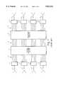
- FIG. 1shows the prior art that utilizes coaxial switching to accomplish interbeam switching at the transponder channel level.
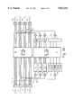
- FIG. 2shows the prior art improvement as described in the Ito et al. patent.
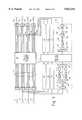
- FIG. 3Ashows a first embodiment of the present invention.
- FIG. 3Bshows an alternative first embodiment of the present invention with a redundant parallel architecture.
- FIG. 4shows a second embodiment of the present invention in which part of the input demultiplexer is bypassed.
- FIG. 5shows a third embodiment of the present invention in which digital techniques are used.
- the standard circuit components found in a satellite repeater systeminclude the low-noise amplifiers, the frequency down-converters (e.g. from 14 GHz to 12 GHz) and the redundancy selection circuits. Such additional circuitry is well known in the art of satellite repeater systems.
- each beamis divided into 4 channels.
- Input beams 1 to 4are fed to the input demultiplexers 5 and the resulting sixteen channels (generally shown at 6) are connected to a coaxial switching network 7 to provide for interbeam connections.
- the reconstituted 16 channels(generally shown at 8) are fed through further processing equipment (e.g. amplifiers) shown at 9 for connection via path (generally shown at 10) to the output multiplexers 11 and for further connection to the beam outputs shown at 12 to 15.
- This prior art systemprovides channel switching of the incoming beams to the outgoing beams, but does not provide any type of subchannelization of the transponder channels.
- input beams 1 to 4are also connected to the input demultiplexers 5 and split into sixteen channels 6. All of the channels (only one channel from each beam is shown in FIG. 2 for simplicity) are downconverted via mixers shown at 16 to an intermediate frequency. After subchannelizing in the SAW filter networks 17, the subchannels are then passed (generally shown at 18) to the GaAs FET switching network 19 for interbeam connection at the subchannel level. The newly reconstituted subchannels are combined in circuits 20 to form new channels 21.
- each of the transponder channelsare likewise subchannelized and each of the subchannels is then switched using the GaAs FET switching network.
- the Ito et al. methodof only partially subchannelizing the transponder channels, or of combining the subchannelization technique with the prior art coaxial switching technique on some portion of the transponder channels.
- radio-frequency signalscomprising each of the four incoming beams shown as 1 to 4 respectively, and arriving at the inputs are each separated by waveguide-cavity demultiplexers 5 into 4 channels generally shown at 6.
- the beamscould come from terrestrial sources or, in the case of intersatellite links, from another satellite).
- the information on each of these derived channelsis packaged so that it could be usefully further divided into subchannels.
- the incoming beamscould be 14 GHz in frequency and channels 54 MHz in bandwidth could be generated.
- One channel of each demultiplexed beamis selected (shown at 28), downconverted via mixers 29 to a lower frequency (e.g. an intermediate frequency of 350 MHz) and fed to the input of a filter bank 54 of SAW filters 67, as described in Ito et al., to form subchannels.
- a filter bank 54 of SAW filters 67as described in Ito et al.
- two subchannelsare 18 MHz in bandwidth and two are 9 MHz in bandwidth.
- These subchannelsare interbeam switched using solid state switches in switching matrix 30: for example, Ito et al, use GaAs FET switches.
- the reconstituted subchannelsare recombined in 32, upconverted through mixers 31 to an appropriate radio frequency such as 12 GHz and form one channel each feeding amplifiers and other appropriate processing or conditioning circuitry (not shown in the drawings). These subchannelized channels are finally fed to the input of the high-power amplifiers and output multiplexers (shown as lumped together in blocks 23) and as taught in Ito et al.
- the reconfigured beams, 32 to 35comprise the output signals.
- the remaining channels that were not selected for subchannelization by feeding to the filter bankare connected into the standard coaxial switching system and processed, interbeam switched and amplified.
- This technologyis well known in the art and is generally depicted by the block 36 (refer also to FIG. 1).
- the output of block 36is frequency translated to 12 GHz (generally this happens prior to demultiplexing in 5) and connected in known fashion to the high-power amplifier and output multiplexer 23, in parallel with the previously described subchannelized channels from the mixers 31.
- a satellite repeateris provided which combines transponder efficiency gains similar to the full subchannelization technique with the power, cost, and weight savings properties of the standard coaxial switching system.
- FIG. 3B of the drawingsan alternative embodiment of the present invention is set forth which is similar to the embodiment of FIG. 3A, but which adds a degree of parallelism and fault tolerance to the repeater.
- this alternative embodimentinstead of only feeding the non-subchannelized channels into the standard coaxial switching network 36, as set forth in FIG. 3A, all of the channels 6, including those fed into the subchannelization network 28 are fed into the standard coaxial switching network 36.
- a plurality of switches 43are interposed between the outputs of the two switching networks and the inputs of the multiplexers in a fashion similar to that disclosed below in connection with FIG. 4.
- This architectureprovides for a degree of parallelism and fault tolerance in the repeater that is not part of the prior art. For example, if one of the SAW filter banks 54 of the repeater failed, that particular channel would still be useful for channel switched information by positioning the switch 43 to select from the output of the coaxial switching network 36. Alternatively, if the coaxial switching network failed, those channels that are routed through the subchannel switching network would still be capable of use by positioning the switches 43 to select from the outputs of the subchannel network.
- This redundant systemis more robust than a single switching network system as taught by the prior art, in that both the coaxial switching network and the subchannelizing switching network have to fail in order for the repeater to be wholly inoperative.
- the incoming radio-frequency signalsare fed in parallel to the input demultiplexers and to the inputs of four novel processors 37.
- the radio-frequency signalpasses through band-limiting, noise-reducing filter 44, which uses resonators of low selectivity (when compared to the selectivity of waveguide cavity resonators in standard input demultiplexers).
- the purpose of filter 44is to suppress out-of-band signals such that noise due to intermodulation and other effects are within acceptable limits for signal traffic.
- the signalis fed from filter 44 to mixer 38 for downconversion to a lower frequency (e.g. an intermediate frequency of 350 MHz).
- the resulting channel signalis then fed through a bank of SAW filters shown at 39 for subchannelization.
- the high selectivity of the SAW filtersserve to provide fine selection of the signals corresponding to one channel only.
- filter 44is of micro-stripline construction, it can be readily integrated into the printed-circuit-board design.
- the filtered signals representing one channelare then connected to solid-state (e.g. GaAs FET) switching matrices 40 and treated from there on as described above, i.e.
- radio-frequency signalsare fed to the input demultiplexers which separate the channels.
- the outputs of the input demultiplexersare sent for coaxial switching in 36 as described before.
- the beam-switched channels from 36are connected to high-power amplifiers and the output multiplexers as well known in the art and generally shown in blocks 23.
- an added feature of this embodimentis that the newly formed subchannelized channels are connected by way of single-pole, double-throw switches 43 to appropriate output channels prior to amplification in high-power amplifiers feeding the output multiplexers. These switches are used to connect selectively either the outputs from the coaxial switching matrix or the outputs from the combining circuits 41 and mixers 42 to the amplifier/multiplexer 23.
- the channels sent for subchannelizingare also separated out in the input demultiplexer and fed to the coaxial switches. This arrangement allows for a degree of redundancy by providing choice of paths, i.e. if, for example, the processors 37 fail, alternate connection paths are available through the coaxial switches. Note that not all switches 43 need be thrown in the same position so that there may be various combinations of connections achieved, i.e. not all of the processors 37 need be in operational use at any one time.
- FIG. 5in another embodiment of the present invention, a digital processor is used to subchannelize and route a set of transponder channels between beams.
- FIG. 5shows the digital processor with inputs from 4 beams. The various sections will be described with reference to FIG. 5.
- the channels for digital subchannelizationcan be selected either before or after the input demultiplexers as described with respect to FIGS. 3 and 4 above.
- the followingdescribes an embodiment in which connection is made prior to the input demultiplexers 5.
- An arrangementsuch as described in FIG. 4 above is used.
- the radio-frequency signalspass through filters 44, such as described above with reference to FIG. 4, and are downconverted in mixers 38 from radio frequency to a lower frequency, i.e. an intermediate frequency such as 350 MHz as described with reference to FIG. 4.
- FIG. 5illustrates that a double downconversion occurs, first via the mixer 38, and then by the Quadrature downconverter 48.
- the dotted outline (block 64)is shown in detail only once. Within the block 64, after filtering of the intermediate frequency in 45, the signal is downconverted to baseband in quadrature downconverter 48 in order to reduce the required sampling rate. It is also possible to use a real downconversion with conversion to complex baseband performed digitally if the analog-to-digital converter has sufficient bandwidth and sampling rate. Note that the reverse of this process occurs in the upconversion chain (shown in dotted outline as block 65 and in detail only once).
- Lowpass filtering and amplificationare supplied by filter 49 and amplifier 50 respectively so that devices operate in their optimal range.
- An anti-aliasing filteris required before digitizing the signal. This can be applied by either bandpass filters 45 before the final downconversion stage (for example with surface-acoustic-wave devices) or by lowpass filters 49 after the final downconversion stage 48.
- the signalsare converted to digital form in analog-to-digital converters 51. They feed into the inputs of digital demultiplexers 52 which take these frequency-multiplexed input signals and pass time-multiplexed signals to the input ports of digital switch 53.
- Demultiplexing in 52can be performed by any number of well-known algorithms such as poly-phase Fast Fourier Transform (FFT) or multistage filtering. The exact selection will depend upon the overall bandwidth and the number of subchannels. As is possible with SAW-based filtering, subchannel filtering can be performed in such a manner that if two contiguous subchannels are switched to the same output beam, the full bandwidth of both subchannels is available with no guardband between them.
- FFTpoly-phase Fast Fourier Transform
- the digital switch 53routes the inputs to different outputs according to a mapping that varies according to the time slot (i.e. subchannel). This mapping can be updated to vary connectivity.
- the outputsgo to the digital multiplexers 55.
- the multiplexers 55perform the exact inverse of processing in the demultiplexers, hence the same algorithms can be used.
- the time-division multiplex signalis converted to a frequency division multiplex signal at the output of the multiplexer.
- the digital signalis converted to analog form by a digital-to-analog converter 56 followed by a lowpass filter 57.
- a real upconversion in mixer 59is illustrated but a complex upconversion can be performed if it is necessary to reduce the requirement on the digital-to-analog converter.
- Gainis applied by amplifier 58 as required to ensure the various devices operate at their optimum range and to ensure output signals are at the correct signal levels.
- the output of the upconversionis filtered by bandpass filter 66 and then goes to either a conventional switch (switching points 43 as described with reference to FIG. 4 are shown as one option) or a high-power amplifier, such as a travelling-wave-tube amplifier.
- the processoris a SAW-based electronics subsystem whose function is to subchannelize 54 MHz transponders into two 9 MHz and two 18 MHz subchannels.
- the 16 subchannelsare recombined, via solid-state switches, in any combination of subchannels to form four new 54 MHz channels, now containing interbeam exchanged information.
- each individual subchannelcan be selected arbitrarily from any of the input beams.
- a subchannel on an input beamwill be routed to only one output beam but in broadcast mode (see the teaching of Ito et al.) a single subchannel or group of subchannels may be routed to multiple outputs and subchannels may be recombined such that all subchannels that make up each new 54 MHz channel have the same downlink (beam) destination.
- the four 54 MHz channelsare then output from the processor and switched into the standard repeater path for downlinking.
- bandwidths of the channelsmay not be equal to each other and may be more or less than 54 MHz.
- more or fewer than four subchannelscould be generated, and these could be of bandwidths to suit specific traffic requirements.
- Meanscould be included in the design (e.g. in the subchannels) to ensure approximate equalization of output power levels.
- Four or eight beamsare given as examples: these are examples only and the invention should not be limited to those numbers of beams.
Landscapes
- Engineering & Computer Science (AREA)
- Computer Networks & Wireless Communication (AREA)
- Signal Processing (AREA)
- Radio Relay Systems (AREA)
Abstract
Description
This invention relates to switching networks associated with multibeam communications satellite repeaters. Prior art multibeam satellite repeaters employed input demultiplexers for dividing incoming beams into a number of transponder channels. Prior to high-power amplification, these channels were interbeam switched by means of coaxial switches so that communications intelligence arriving at the satellite via one of the incoming beams could be directed to one of several output beams. These connections were made on a relatively broad channel basis, i.e. all of the information in one transponder channel had to be switched as a packet onto the outgoing channel.
Recently, a number of important developments have occurred in the mobile communications markets. For the hand-held-terminal market, interest is now focused on low-earth-orbit (LEO) and medium-earth-orbit (MEO) satellite constellations. The fixed (geostationary or GEO) market is also undergoing major changes. Traditional point-to-point communications between major population centers are being converted to optical fiber and operators are now looking to provide a far greater number of narrowbandwidth links, principally to areas that are not well served by existing terrestrial infrastructure. To this end, recently proposed satellites have more beams, higher effective isotropic radiated power (EIRP) and greater interbeam connectivity so that users will require less expensive ground terminals. These trends are being accelerated by data compression which is forcing operators to lease comparatively narrow bandwidths.
The mounting demand for greater connectivity and leases of fractions of transponders cannot be satisfied by simply increasing the number of beams since this aggravates the connectivity problem and leads to reduced transponder utilization efficiency.
The problem of interconnecting narrowbandwidth links was addressed by Ito et al. in U.S. Pat. No. 4,706,239 issued Nov. 12, 1987 and assigned to Kokusai Denshin Denwa Co. Ltd. In the Ito et al patent, each incoming radio-frequency beam is divided first into transponder channels by means of a demultiplexer as is well known in the art. Each channel is then downconverted to an intermediate frequency and further divided into subchannels by use of surface-acoustic-wave (SAW) filters. Interbeam switching is then carried out using GaAs FET switches at the relatively narrow subchannel level, rather than at the channel level as in prior systems The output of the switches are subsequently multiplexed back into transponder channels, and upconverted to radio-frequency for amplification and multiplexing into output beams.
The Ito et al. development allows for significant improvements in satellite use by enabling greater transponder efficiency while reacting to the demand for switching of narrower bandwidth information packets. In addition, the Ito et al. improvement permits the uplinked input information at the subchannel bandwidth level to be simultaneously connected to a number of output beams, thereby permitting narrowband information broadcasting to several reception points.
There are certain conditions that must be satisfied for this form of subchannelization to be useful. First, the satellite must have multiple beams: in a system with one uplink and one downlink all traffic would have a single source and a single destination and independently switched subchannels would produce no benefit. Second, the operator must lease fractional transponders.
If these conditions are satisfied, then, in general, there will be links on the satellite with requirements for a fraction of a transponder. For example, the traffic volume from an uplink to a downlink might occupy 2.2 transponders. In this case, a system without subchannelization would require three full transponders to serve only 2.2 transponders worth of traffic. The purpose of the subchannelization is to manage the fractional part of the traffic, 0.2 of a transponder in this example, in the various links. A single subchannel could then be used for this fractional part of the traffic, leaving the other subchannels free for use in other links. The integral part of the traffic, 2 transponders in this example, could use ordinary transponder channels without loss of efficiency.
If surplus transponders are available, then partially occupied transponders are not a problem. However, the number of transponders is limited by several considerations such as cost, internationally agreed spectrum allocations, and the available power on the satellite bus. Multibeam satellites are generally power-limited. In the current state of the art, an 8-beam satellite would typically support 4 transponders per beam, though this may increase to 8 transponders per beam in the foreseeable future with the introduction of very-high-power buses. In such multibeam systems, a substantial proportion of the transponders would be partially occupied. Subchannelization allows more efficient operation of the satellite without increasing the total number of transponders. The actual capacity increase produced by subchannelization is dependent on system configuration and traffic patterns, but is typically 25%.
The major disadvantages of the Ito et al. system are the increases in the cost, mass and power budgets of the satellite to support the subchannelization of each transponder channel. The additional hardware increases, the initial system cost, and the increase in mass and power consumption (leading to an increase in power-supply hardware) must be compensated by a reduced fuel load, which in turn reduces satellite lifetime and hence long-term revenue. These factors would significantly offset the advantages of the 25% efficiency improvement gained by using the Ito method to subchannelize each of the transponder channels, and hence this method has proven to be unsatisfactory.
In the Ito et al. system, for an 8-beam, 8-channel satellite, 8 processors would be employed, each providing full 8-beam connectivity at the subchannel level. This would require substantial hardware and, consequently, would cause a substantial power drain on the satellite power bus, would increase the total mass of the satellite, and would cause an increase in the cost of both the satellite and the launch. In addition, the present inventors have conducted traffic-pattern studies which indicate that the Ito et al. full subchannelization method would not provide significantly superior performance to a satellite system with only a portion of the transponder channels subchannelized. The reason for this result is that subchannelization is useful only for managing the fractional portion of the overall satellite traffic pattern. For example, if a certain user of the satellite required the bandwidth of an entire transponder channel for its information, then subchannelization of that channel is a waste of system resources. It is therefore only worthwhile to subchannelize sufficient channels to accommodate the fractional traffic in the various links: the integral traffic volumes can then be handled by conventional transponders and switch matrices. Such an arrangement minimizes the impact of the processors on the cost, mass and power budgets, while preserving most of the benefit. In addition, further reviews indicate that a full 8-by-8 connectivity for each processor would give only marginally better performance than suitably configured 4-by-4 processors.
The inventors have discovered that, by combining the coaxial switch methods with the subchannelization methods taught by Ito et al., similar advantages to those of the Ito et al. system can be obtained with greatly reduced hardware complexity, and with greatly diminished power requirements, hardware and launch costs and satellite mass. For example, the traffic pattern studies conducted by the present inventors have indicated that in the 8-beam, 8-channel system considered above, subchannelizing 4 channels would typically produce a 20% capacity improvement, while subchannelizing all 8, as proposed by Ito et al., would produce only a 25 % improvement. The marginal gains that can be made by going from 4 to 8 subchannelized channels do not justify the associated doubling or, possibly, quadrupling in the amount of processor hardware. The major disadvantages of the Ito et al. full subchannelizing system lies in the increase in cost, power, weight and volume budgets for a satellite. The added cost of building, launching and operating the more complex Ito et al. satellite offsets the increase in customer revenues due to the marginally more efficient use of the satellite.
The present invention combines the coaxial switching methods with the subchannelization method taught by Ito et al., wherein only a portion of the transponder channels are subchannelized, the remainder of the channels being switched using the coaxial switching method, thus enabling the commissioning of relatively inexpensive subchannelizing systems that offer more efficient transponder utilization than standard coaxial switching systems, and do so at much lower cost, weight, and power consumption than the full subchannelized system of Ito et al. The present invention thus offers new commercial opportunities hitherto not realizable. For example, service to remote communities becomes more attractive. These services would include telephone services as well as, possibly, some form of cellular service such as described in U.S. Pat. No. 5,081,703 by Lee et al, issued on 9 Jan. 1992 and assigned to PACTEL CORPORATION.
FIG. 1 shows the prior art that utilizes coaxial switching to accomplish interbeam switching at the transponder channel level.
FIG. 2 shows the prior art improvement as described in the Ito et al. patent.
FIG. 3A shows a first embodiment of the present invention.
FIG. 3B shows an alternative first embodiment of the present invention with a redundant parallel architecture.
FIG. 4 shows a second embodiment of the present invention in which part of the input demultiplexer is bypassed.
FIG. 5 shows a third embodiment of the present invention in which digital techniques are used.
Not shown in the drawings or discussed to any extent in the description are the standard circuit components found in a satellite repeater system. These include the low-noise amplifiers, the frequency down-converters (e.g. from 14 GHz to 12 GHz) and the redundancy selection circuits. Such additional circuitry is well known in the art of satellite repeater systems.
Referring to FIG. 1, consideration is given to a prior art 4-beam satellite in which each beam is divided into 4 channels. Input beams 1 to 4 are fed to theinput demultiplexers 5 and the resulting sixteen channels (generally shown at 6) are connected to a coaxial switching network 7 to provide for interbeam connections. The reconstituted 16 channels (generally shown at 8) are fed through further processing equipment (e.g. amplifiers) shown at 9 for connection via path (generally shown at 10) to theoutput multiplexers 11 and for further connection to the beam outputs shown at 12 to 15. This prior art system provides channel switching of the incoming beams to the outgoing beams, but does not provide any type of subchannelization of the transponder channels.
Referring to FIG. 2, the prior art system of Ito et al. teaches that, for the 4-by-4 satellite described above, input beams 1 to 4 are also connected to theinput demultiplexers 5 and split into sixteenchannels 6. All of the channels (only one channel from each beam is shown in FIG. 2 for simplicity) are downconverted via mixers shown at 16 to an intermediate frequency. After subchannelizing in theSAW filter networks 17, the subchannels are then passed (generally shown at 18) to the GaAsFET switching network 19 for interbeam connection at the subchannel level. The newly reconstituted subchannels are combined incircuits 20 to formnew channels 21. These channels are upconverted viamixers 22 and fed to the high-power amplifiers and output multiplexer, shown lumped together asblock 23, for onward transmission to the 4 output beam feeds shown as 24 to 27. The connectivity is the same as shown in FIG. 1, but it is now provided at the subchannel, rather than at the channel, level. In the Ito et al. prior art method each of the transponder channels are likewise subchannelized and each of the subchannels is then switched using the GaAs FET switching network. There is no teaching or disclosure by the Ito et al. method of only partially subchannelizing the transponder channels, or of combining the subchannelization technique with the prior art coaxial switching technique on some portion of the transponder channels.
Referring now to FIG. 3A in the drawings, in one embodiment of the present invention, radio-frequency signals comprising each of the four incoming beams shown as 1 to 4 respectively, and arriving at the inputs are each separated by waveguide-cavity demultiplexers 5 into 4 channels generally shown at 6. (The beams could come from terrestrial sources or, in the case of intersatellite links, from another satellite). Usually, the information on each of these derived channels is packaged so that it could be usefully further divided into subchannels. (See Ito et al.) For example, the incoming beams could be 14 GHz in frequency andchannels 54 MHz in bandwidth could be generated. One channel of each demultiplexed beam is selected (shown at 28), downconverted viamixers 29 to a lower frequency (e.g. an intermediate frequency of 350 MHz) and fed to the input of afilter bank 54 of SAW filters 67, as described in Ito et al., to form subchannels. In this embodiment, two subchannels are 18 MHz in bandwidth and two are 9 MHz in bandwidth. These subchannels are interbeam switched using solid state switches in switching matrix 30: for example, Ito et al, use GaAs FET switches. The reconstituted subchannels are recombined in 32, upconverted throughmixers 31 to an appropriate radio frequency such as 12 GHz and form one channel each feeding amplifiers and other appropriate processing or conditioning circuitry (not shown in the drawings). These subchannelized channels are finally fed to the input of the high-power amplifiers and output multiplexers (shown as lumped together in blocks 23) and as taught in Ito et al. The reconfigured beams, 32 to 35, comprise the output signals.
The remaining channels that were not selected for subchannelization by feeding to the filter bank are connected into the standard coaxial switching system and processed, interbeam switched and amplified. This technology is well known in the art and is generally depicted by the block 36 (refer also to FIG. 1). The output ofblock 36 is frequency translated to 12 GHz (generally this happens prior to demultiplexing in 5) and connected in known fashion to the high-power amplifier andoutput multiplexer 23, in parallel with the previously described subchannelized channels from themixers 31. In this fashion, a satellite repeater is provided which combines transponder efficiency gains similar to the full subchannelization technique with the power, cost, and weight savings properties of the standard coaxial switching system.
Referring now to FIG. 3B of the drawings, an alternative embodiment of the present invention is set forth which is similar to the embodiment of FIG. 3A, but which adds a degree of parallelism and fault tolerance to the repeater. In this alternative embodiment, instead of only feeding the non-subchannelized channels into the standardcoaxial switching network 36, as set forth in FIG. 3A, all of thechannels 6, including those fed into thesubchannelization network 28 are fed into the standardcoaxial switching network 36. In order to accommodate the redundant channels that are both channel-switched by thecoaxial network 36, and subchannelized and switched by thesubchannel network 30, a plurality ofswitches 43 are interposed between the outputs of the two switching networks and the inputs of the multiplexers in a fashion similar to that disclosed below in connection with FIG. 4. This architecture provides for a degree of parallelism and fault tolerance in the repeater that is not part of the prior art. For example, if one of theSAW filter banks 54 of the repeater failed, that particular channel would still be useful for channel switched information by positioning theswitch 43 to select from the output of thecoaxial switching network 36. Alternatively, if the coaxial switching network failed, those channels that are routed through the subchannel switching network would still be capable of use by positioning theswitches 43 to select from the outputs of the subchannel network. This redundant system is more robust than a single switching network system as taught by the prior art, in that both the coaxial switching network and the subchannelizing switching network have to fail in order for the repeater to be wholly inoperative.
In another embodiment of the present invention shown in FIG. 4, the incoming radio-frequency signals are fed in parallel to the input demultiplexers and to the inputs of fournovel processors 37. (To avoid confusion in the understanding, only oneprocessor 37 is shown in detail and the following will describe the operation of just one processor 37). The radio-frequency signal passes through band-limiting, noise-reducingfilter 44, which uses resonators of low selectivity (when compared to the selectivity of waveguide cavity resonators in standard input demultiplexers). The purpose offilter 44 is to suppress out-of-band signals such that noise due to intermodulation and other effects are within acceptable limits for signal traffic. The signal is fed fromfilter 44 tomixer 38 for downconversion to a lower frequency (e.g. an intermediate frequency of 350 MHz). The resulting channel signal is then fed through a bank of SAW filters shown at 39 for subchannelization. The high selectivity of the SAW filters serve to provide fine selection of the signals corresponding to one channel only. One could choose, therefore, to design input demultiplexers that drop the channels that are treated in the SAW filter processor. However, as will be explained below, it is preferred to pass all channels through the standard coaxial switching system for reasons of redundancy. Iffilter 44 is of micro-stripline construction, it can be readily integrated into the printed-circuit-board design. The filtered signals representing one channel are then connected to solid-state (e.g. GaAs FET) switchingmatrices 40 and treated from there on as described above, i.e. combined in a known way in circuits shown at 41 and subsequently upconverted in mixers shown at 42. In parallel with the subchannelizing activity, radio-frequency signals are fed to the input demultiplexers which separate the channels. The outputs of the input demultiplexers are sent for coaxial switching in 36 as described before. The beam-switched channels from 36 are connected to high-power amplifiers and the output multiplexers as well known in the art and generally shown inblocks 23.
An added feature of this embodiment is that the newly formed subchannelized channels are connected by way of single-pole, double-throw switches 43 to appropriate output channels prior to amplification in high-power amplifiers feeding the output multiplexers. These switches are used to connect selectively either the outputs from the coaxial switching matrix or the outputs from the combiningcircuits 41 andmixers 42 to the amplifier/multiplexer 23. In this example, the channels sent for subchannelizing are also separated out in the input demultiplexer and fed to the coaxial switches. This arrangement allows for a degree of redundancy by providing choice of paths, i.e. if, for example, theprocessors 37 fail, alternate connection paths are available through the coaxial switches. Note that not allswitches 43 need be thrown in the same position so that there may be various combinations of connections achieved, i.e. not all of theprocessors 37 need be in operational use at any one time.
Now turning to FIG. 5, in another embodiment of the present invention, a digital processor is used to subchannelize and route a set of transponder channels between beams. FIG. 5 shows the digital processor with inputs from 4 beams. The various sections will be described with reference to FIG. 5.
The channels for digital subchannelization can be selected either before or after the input demultiplexers as described with respect to FIGS. 3 and 4 above. The following describes an embodiment in which connection is made prior to theinput demultiplexers 5. An arrangement such as described in FIG. 4 above is used. The radio-frequency signals pass throughfilters 44, such as described above with reference to FIG. 4, and are downconverted inmixers 38 from radio frequency to a lower frequency, i.e. an intermediate frequency such as 350 MHz as described with reference to FIG. 4.
FIG. 5 illustrates that a double downconversion occurs, first via themixer 38, and then by theQuadrature downconverter 48. The dotted outline (block 64) is shown in detail only once. Within theblock 64, after filtering of the intermediate frequency in 45, the signal is downconverted to baseband inquadrature downconverter 48 in order to reduce the required sampling rate. It is also possible to use a real downconversion with conversion to complex baseband performed digitally if the analog-to-digital converter has sufficient bandwidth and sampling rate. Note that the reverse of this process occurs in the upconversion chain (shown in dotted outline asblock 65 and in detail only once). Lowpass filtering and amplification are supplied byfilter 49 andamplifier 50 respectively so that devices operate in their optimal range. An anti-aliasing filter is required before digitizing the signal. This can be applied by eitherbandpass filters 45 before the final downconversion stage (for example with surface-acoustic-wave devices) or bylowpass filters 49 after thefinal downconversion stage 48.
The signals are converted to digital form in analog-to-digital converters 51. They feed into the inputs ofdigital demultiplexers 52 which take these frequency-multiplexed input signals and pass time-multiplexed signals to the input ports ofdigital switch 53. Demultiplexing in 52 can be performed by any number of well-known algorithms such as poly-phase Fast Fourier Transform (FFT) or multistage filtering. The exact selection will depend upon the overall bandwidth and the number of subchannels. As is possible with SAW-based filtering, subchannel filtering can be performed in such a manner that if two contiguous subchannels are switched to the same output beam, the full bandwidth of both subchannels is available with no guardband between them.
Thedigital switch 53 routes the inputs to different outputs according to a mapping that varies according to the time slot (i.e. subchannel). This mapping can be updated to vary connectivity. The outputs go to thedigital multiplexers 55.
Themultiplexers 55 perform the exact inverse of processing in the demultiplexers, hence the same algorithms can be used. The time-division multiplex signal is converted to a frequency division multiplex signal at the output of the multiplexer. The digital signal is converted to analog form by a digital-to-analog converter 56 followed by alowpass filter 57. A real upconversion inmixer 59 is illustrated but a complex upconversion can be performed if it is necessary to reduce the requirement on the digital-to-analog converter. Gain is applied byamplifier 58 as required to ensure the various devices operate at their optimum range and to ensure output signals are at the correct signal levels. After further filtering in 60 and amplification (61), the output of the upconversion (mixer 62) is filtered bybandpass filter 66 and then goes to either a conventional switch (switching points 43 as described with reference to FIG. 4 are shown as one option) or a high-power amplifier, such as a travelling-wave-tube amplifier.
In the embodiments of the present invention exemplified by FIGS. 3 and 4, the processor is a SAW-based electronics subsystem whose function is to subchannelize 54 MHz transponders into two 9 MHz and two 18 MHz subchannels. Under operator control, the 16 subchannels are recombined, via solid-state switches, in any combination of subchannels to form four new 54 MHz channels, now containing interbeam exchanged information. However, each individual subchannel can be selected arbitrarily from any of the input beams.
Normally, a subchannel on an input beam will be routed to only one output beam but in broadcast mode (see the teaching of Ito et al.) a single subchannel or group of subchannels may be routed to multiple outputs and subchannels may be recombined such that all subchannels that make up each new 54 MHz channel have the same downlink (beam) destination. The four 54 MHz channels are then output from the processor and switched into the standard repeater path for downlinking.
In the specification, various embodiments have been shown and examples have been given. Modifications can be made without departing from the spirit of the invention. For example, bandwidths of the channels may not be equal to each other and may be more or less than 54 MHz. Also, more or fewer than four subchannels could be generated, and these could be of bandwidths to suit specific traffic requirements. Means could be included in the design (e.g. in the subchannels) to ensure approximate equalization of output power levels. Four or eight beams are given as examples: these are examples only and the invention should not be limited to those numbers of beams.
Reference has been made to the use of coaxial switching matrices. It would be recognized by those skilled in the art that other forms of electro-mechanical radio-frequency switches may be used. For example, waveguide switches may be substituted, especially where high radio frequencies, e.g. Ka-Band and higher, are to be used.
The embodiments of the invention in which an exclusive property or privilege is claimed are defined as follows:
Claims (17)
1. A communications repeater for a multibeam satellite in which a satellite radio-frequency communications band for each beam is comprised of a plurality of associated channels, each channel containing intelligence separable into distinct subchannels, said satellite repeater having an input demultiplexer for each incoming beam for dividing beams into channels and an output multiplexer for each outgoing beam for combining channels into beams wherein the improvement comprises the combination of:
first means for interbeam switching a plurality of the channels produced at the output of said input demultiplexers, thereby creating a set of interbeam-switched channels;
means for selecting and for dividing into subchannels at least one channel from each of at least two of the incoming beams, wherein each said means for selecting and for dividing is connected to an output of an input demultiplexer and includes a frequency downconverter in series with a bank of surface-acoustic-wave filters;
second means for interbeam switching the subchannels produced by dividing the selected channels;
means for combining the interbeam-switched subchannels into a set of interbeam-switched subchannelized channels; and
means for connecting the interbeam-switched channels and the interbeam-switched subchannelized channels to the inputs of the output multiplexers.
2. A communications repeater for a multibeam satellite in which a satellite radio-frequency communications band for each beam is comprised of a plurality of associated channels, each channel containing intelligence separable into distinct subchannels, said satellite repeater having an input demultiplexer for each incoming beam for dividing beams into channels and an output multiplexer for each outgoing beam for combining channels into beams wherein the improvement comprises the combination of:
first means for interbeam switching a plurality of the channels produced at the output of said input demultiplexers, thereby creating a set of interbeam-switched channels;
means for selecting and for dividing into subchannels at least one channel from each of at least two of the incoming beams, wherein each said means for selecting and dividing is connected to an input of an input demultiplexer and includes, in series, a band-limiting filter, a frequency downconverter and a bank of surface-acoustic-wave filters;
second means for interbeam switching the subchannels produced by dividing the selected channels;
means for combining the interbeam-switched subchannels into a set of interbeam-switched subchannelized channels; and
means for connecting the interbeam-switched channels and the interbeam-switched subchannelized channels to the inputs of the output multiplexers.
3. A communications repeater for a multibeam satellite in which a satellite radio-frequency communications hand for each beam is comprised of a plurality of associated channels, each channel containing intelligence separable into distinct subchannels, said satellite repeater having an input demultiplexer for each incoming beam for dividing beams into channels and an output multiplexer for each outgoing beam for combining channels into beams wherein the improvement comprises the combination of:
first means for interbeam switching a plurality of the channels produced at the output of said input demultiplexers, thereby creating a set of interbeam-switched channels;
means for selecting and for dividing into subchannels at least one channel from each of at least two of the incoming beams, wherein each said means for selecting and dividing is connected to an input of an input demultiplexer and includes means for converting each selected channel to a digital format and digital multiplexer means to divide the converted selected channels into subchannels;
second means for interbeam switching the subchannels produced by dividing the selected channels;
means for combining the interbeam-switched subchannels into a set of interbeam-switched subchannelized channels; and
means for connecting the interbeam-switched channels and the interbeam-switched subchannelized channels to the inputs of the output multiplexers.
4. A communications repeater for a multibeam satellite in which a satellite radio-frequency communications band for each beam is comprised of a plurality of associated channels, each channel containing intelligence separable into distinct subchannels, said satellite repeater having an input demultiplexer for each incoming beam for dividing beams into channels and an output multiplexer for each outgoing beam for combining channels into beams wherein the improvement comprises the combination of:
first means for interbeam switching a plurality of the channels produced at the output of said input demultiplexers, thereby creating a set of interbeam-switched channels;
means for selecting and for dividing into subchannels at least one channel from each of at least two of the incoming beams;
second means for interbeam switching the subchannels produced by dividing the selected channel, wherein said second means for interbeam switching comprises a solid-state switching network;
means for combining the interbeam-switched subchannels into a set of interbeam-switched subchannelized channels; and
means for connecting the interbeam-switched channels and the interbeam-switched subchannelized channels to the inputs of the output multiplexers.
5. A communications repeater for a multibeam satellite in which a satellite radio-frequency communications band for each beam is comprised of a plurality of associated channels, each channel containing intelligence separable into distinct subchannels, said satellite repeater having an input demultiplexer for each incoming beam for dividing beams into channels and an output multiplexer for each outgoing beam for combining channels into beams wherein the improvement comprises the combination of:
first means for interbeam switching a plurality of the channels produced at the output of said input demultiplexers, thereby creating a set of interbeam-switched channels;
means for selecting and for dividing into subchannels at least one channel from each of at least two of the incoming beams;
second means for interbeam switching the subchannels produced by dividing the selected channels, wherein said second means for interbeam switching comprises a matrix of GaAs FET devices;
means for combining the interbeam-switched subchannels into a set of interbeam-switched subchannelized channels; and
means for connecting the interbeam-switched channels and the interbeam-switched subchannelized channels to the inputs of the output multiplexers.
6. A communications repeater for a multibeam satellite in which a satellite radio-frequency communications band for each beam is comprised of a plurality of associated channels, each channel containing intelligence separable into distinct subchannels, said satellite repeater having an input demultiplexer for each incoming beam for dividing beams into channels and an output multiplexer for each outgoing beam for combining channels into beams wherein the improvement comprises the combination of:
first means for interbeam switching a plurality of the channels produced at the output of said input demultiplexers, thereby creating a set of interbeam-switched channels;
means for selecting and for dividing into subchannels at least one channel from each of at least two of the incoming beams;
second means for interbeam switching the subchannels produced by dividing the selected channels;
means for combining the interbeam-switched subchannels into a set of interbeam-switched subchannelized channels; and
means for connecting the interbeam-switched channels and interbeam-switched subchannelized channels to the inputs of the output multiplexers, wherein said means for connecting includes a switch for selectively connecting either an interbeam-switched channel or an interbeam-switched subchannelized channel, to the input of an output multiplexer.
7. A communications repeater for a multibeam satellite in which a satellite radio-frequency communications band for each beam is comprised of a plurality of associated channels, each channel containing intelligence separable into distinct subchannels, said satellite repeater having an input demultiplexer for each incoming beam for dividing beams into channels and an output multiplexer for each outgoing beam for combining channels into beams, wherein the improvement comprises the combination of:
a coaxial switching matrix connected to the outputs of said input demultiplexers for interbeam switching, at radio frequency, channels produced at the output of said input demultiplexers, thereby to create a set of interbeam-switched channels;
frequency downconversion circuits connected to the input demultiplexers, each of said downconversion circuits downconverting the channels associated with an input beam to an intermediate frequency;
a bank of surface-acoustic-wave filters connected to the output of each frequency downconversion circuit to divide, at an intermediate frequency, the channel into frequency-spaced subchannels;
a solid-state matrix connected to the outputs of the banks of filters for interbeam switching the subchannels produced by the filter banks;
a solid-state network for combining the interbeam-switched subchannels into a set of interbeam-switched subchannelized channels;
frequency upconversion circuits connected to the outputs of the solid-state network to convert the set of interbeam-switched subchannelized channels to radio frequency; and
connection circuitry, including amplifiers and filtering circuits, to connect the interbeam-switched channels and the interbeam-switched subchannelized channels to the inputs to the output multiplexers.
8. The communications repeater according to claim 7, wherein each frequency downconversion circuit is connected to at least one output of each of at least two input demultiplexers, said frequency downconversion circuits downconverting the demultiplexed channels to an intermediate frequency.
9. The communications repeater according to claim 7, wherein each frequency downconversion circuit is connected, through band-limiting filters, to the input of at least two input demultiplexers, said frequency downconversion circuits each downconverting signals representing a channel to an intermediate frequency.
10. A communications repeater for a multibeam satellite in which a satellite radio-frequency communications band for each beam is comprised of a plurality of associated channels, each channel containing intelligence separable into distinct subchannels, said satellite repeater having an input demultiplexer for each incoming beam for dividing beams into channels and an output multiplexer for each outgoing beam for combining channels into beams, wherein the improvement comprises the combination of:
a coaxial switching matrix connected to the outputs of said input demultiplexers for interbeam switching, at radio frequency, said channels produced at the output of said input demultiplexers, thereby to create a set of interbeam-switched channels;
frequency downconverting circuits connected, through band-limiting filters, to the inputs of at least two input demultiplexers, said circuits downconverting the signals at the outputs of said band-limiting filters to an intermediate frequency, the down-converted signals representing at least two selected channels;
a bandpass filter connected to the output of each frequency downconverting circuit and each connected to the input of a quadrature downconverter;
each said quadrature downconverter connected to the output of the bandpass filter to convert the selected channel to baseband;
first lowpass filters connected to the outputs of each quadrature downconverter;
analog-to-digital converters for receiving the output signals from the first lowpass filters for converting the baseband signal to digital format;
digital demultiplexers connected to the outputs of the analog-to-digital converters to divide the digital signals into subchannels, each subchannel being represented by a time slot;
a digital switch connected to the outputs of the digital demultiplexers for routing the subchannels in their time slots to digital multiplexing circuits, said digital multiplexing circuits serving to combine the subchannels into a set of interbeam-switched subchannelized channels;
digital-to-analog converters connected to the outputs of the digital multiplexing circuits for converting the interbeam-switched subchannelized channels to analog format;
second lowpass filters connected to the output of said digital-to-analog converters for smoothing the digital-to-analog output signal and filtering of upper-frequency images;
upconverting circuits for converting the outputs of the second lowpass filters to radio frequency;
connecting circuitry, including amplifiers and filtering circuits, to connect the interbeam-switched channels and the interbeam-switched subchannelized channels to the inputs to the output multiplexers.
11. The communications repeater of claim 10 in which the bandpass filter is an anti-aliasing filter to restrict the signals at its output to those of one of the selected channels only.
12. The communications repeater of claim 10 in which the lowpass filter is an anti-aliasing filter to restrict the signals at its output to those of one of the selected channels only.
13. A communications repeater for use with a multibeam satellite, said repeater comprising:
a plurality of input demultiplexers, wherein each input demultiplexer is connected to an input beam, and wherein each input demultiplexer separates the input beam into a plurality of channels;
a coaxial switching network connected to some, but not all, of the plurality of channels, wherein said coaxial switching network switches the connected channels to form a set of interbeam-switched channels;
a subchannelizing and solid state switching circuit connected to the plurality of channels which are not connected to the coaxial switching network, wherein the circuit separates the connected channels into subchannels, switches the subchannels, and forms a set of interbeam-switched subchannelized channels;
a plurality of output demultiplexers, wherein each output demultiplexer is connected to at least one of the interbeam-switched channels and at least one of the interbeam-switched subchannelized channels, and wherein the output of each output demultiplexer forms an output beam.
14. The satellite repeater according to claim 13, wherein the subchannelizing and solid state switching circuit includes a plurality of downconversion mixers and banks of surface-acoustic-wave filters that separate each connected channel into subchannels.
15. The satellite repeater according to claim 14, wherein the subchannelizing and solid state switching circuit includes a FET switching network connected to the banks of surface-acoustic-wave filters, wherein the FET switching network switches the subchannels onto its outputs.
16. The satellite repeater according to claim 15, wherein the subchannelizing and solid state switching circuit includes a plurality of recombining and upconversion circuits, wherein each recombining and upconversion circuit is connected to a plurality of outputs from the FET switching network, and wherein the outputs from the plurality of recombining and upconversion circuits forms the set of interbeam-switched subchannelized channels.
17. A communications repeater for use with a multibeam satellite, said repeater comprising:
a plurality of input demultiplexers, wherein each input demultiplexer is connected to an input beam, and wherein each input demultiplexer separates the input beam into a plurality of channels;
a coaxial switching network connected to the plurality of channels, wherein the coaxial switching network switches the channels to form a set of interbeam-switched channels;
a filtering, subchannelizing and solid state switching processor connected to at least one of the input beams, wherein said processor includes narrow bandpass filters that filter the input beam into a representative channel, wherein said processor further includes separation circuitry that separates the filtered channel into subchannels, and wherein said processor further includes subchannel switches that switch the separated subchannels to form a set of interbeam-switched subchannelized channels;
a plurality of channel switches, wherein each of said channel switches is connected to at least one interbeam-switched channel and at least one interbeam-switched subchannelized channel, and wherein the switch is used to selectively connect either the interbeam-switched channel or the interbeam-switched subchannelized channel onto the channel switch output;
a plurality of output multiplexers, each output multiplexer connected to at least one of the interbeam-switched channels and at least one channel switch output, the output of each output demultiplexer forming an output beam.
Priority Applications (3)
| Application Number | Priority Date | Filing Date | Title |
|---|---|---|---|
| DE69626905TDE69626905T2 (en) | 1995-08-30 | 1996-08-13 | Satellite repeater for switching radio lobes of channels and subchannels |
| EP19960113034EP0760561B9 (en) | 1995-08-30 | 1996-08-13 | Repeaters for multibeam satellites with channels divided in subchannels and interbeam switching |
| NO963548ANO963548L (en) | 1995-08-30 | 1996-08-26 | Repeater device for multi-jet satellites |
Applications Claiming Priority (2)
| Application Number | Priority Date | Filing Date | Title |
|---|---|---|---|
| CA2157209 | 1995-08-30 | ||
| CA002157209ACA2157209C (en) | 1995-08-30 | 1995-08-30 | Repeaters for multibeam satellites |
Publications (1)
| Publication Number | Publication Date |
|---|---|
| US5822312Atrue US5822312A (en) | 1998-10-13 |
Family
ID=4156509
Family Applications (1)
| Application Number | Title | Priority Date | Filing Date |
|---|---|---|---|
| US08/633,676Expired - LifetimeUS5822312A (en) | 1995-08-30 | 1996-04-17 | Repeaters for multibeam satellites |
Country Status (2)
| Country | Link |
|---|---|
| US (1) | US5822312A (en) |
| CA (1) | CA2157209C (en) |
Cited By (22)
| Publication number | Priority date | Publication date | Assignee | Title |
|---|---|---|---|---|
| WO1999043104A1 (en)* | 1998-02-18 | 1999-08-26 | Viasat, Inc. | Method for improving inter-beam capacity switching for multiple spot beam satellite systems |
| WO2001001606A1 (en)* | 1999-06-25 | 2001-01-04 | Qualcomm Incorporated | Feeder link spatial multiplexing in a satellite communication system |
| US6188874B1 (en)* | 1997-06-27 | 2001-02-13 | Lockheed Martin Corporation | Control and telemetry signal communication system for geostationary satellites |
| US6229986B1 (en)* | 1998-11-18 | 2001-05-08 | Hughes Electronics Corporation | Reconfigurable analog channel processor for multibeam satellites |
| US6341213B1 (en)* | 1999-08-11 | 2002-01-22 | Hughes Electronics Corporation | Dynamic repeater configuration for multilink satellite systems with robust subchannel interconnect capability |
| US6469984B1 (en) | 1999-06-24 | 2002-10-22 | Qualcomm Incorporated | Method and system for monitoring traffic on a code division multiple access repeater |
| US20030068979A1 (en)* | 2001-10-05 | 2003-04-10 | The Boeing Company | Satellite transponder architecture with integral redundancy and beam selection capabilities |
| US6704543B1 (en) | 1999-09-27 | 2004-03-09 | Ems Technologies, Inc. | Multi-beam satellite communications system |
| US6836658B1 (en) | 2000-03-03 | 2004-12-28 | Ems Technologies, Inc. | High data rate satellite communications system and method |
| US20050053164A1 (en)* | 2003-07-09 | 2005-03-10 | Severine Catreux | System and method for RF signal combining and adaptive bit loading for data rate maximization in multi-antenna communication systems |
| US20050078622A1 (en)* | 2003-10-09 | 2005-04-14 | Dicamillo Nicholas F. | Signal processing apparatus and method, and communication system utilizing same |
| US20060029146A1 (en)* | 2003-03-17 | 2006-02-09 | Severine Catreux | Multi-antenna communication systems utilizing RF-based and baseband signal weighting and combining |
| US20060072514A1 (en)* | 2003-07-09 | 2006-04-06 | Mark Kent | Method and system for single weight (SW) antenna system for spatial multiplexing (SM) MIMO system for WCDMA/HSDPA |
| US20090295628A1 (en)* | 2006-09-26 | 2009-12-03 | Viasat, Inc. | Satellite System Optimization |
| US20100027411A1 (en)* | 2005-10-26 | 2010-02-04 | Thomson Licensing | System and Method for Compensating for a Satellite Gateway Failure |
| US20110058518A1 (en)* | 2009-09-09 | 2011-03-10 | Comtech Ef Data Corp. | Multi-Channel Single Carrier Per Channel (SCPC) Systems and Related Methods |
| US20110317620A1 (en)* | 2009-12-18 | 2011-12-29 | Thales | Multi-Spot Transmission and Reception System on Board a Satellite and Satellite Comprising Such a System |
| US8185075B2 (en) | 2003-03-17 | 2012-05-22 | Broadcom Corporation | System and method for channel bonding in multiple antenna communication systems |
| US20120244798A1 (en)* | 2006-09-26 | 2012-09-27 | Viasat, Inc. | Frequency re-use for service and gateway beams |
| US9503149B1 (en)* | 2015-07-28 | 2016-11-22 | Beijing Lenovo Software Ltd. | Electronic device and control method thereof |
| US9848370B1 (en)* | 2015-03-16 | 2017-12-19 | Rkf Engineering Solutions Llc | Satellite beamforming |
| US20200059379A1 (en)* | 2018-08-08 | 2020-02-20 | Daegu Gyeongbuk Institute Of Science And Technology | System for network using bus protocol |
Citations (41)
| Publication number | Priority date | Publication date | Assignee | Title |
|---|---|---|---|---|
| US3548108A (en)* | 1965-02-27 | 1970-12-15 | Nippon Electric Co | Telegraph and telephone switching system utilizing a stationary satellite |
| US3636452A (en)* | 1969-08-28 | 1972-01-18 | Licentia Gmbh | Radio relay system |
| US4029902A (en)* | 1975-10-22 | 1977-06-14 | Hughes Aircraft Company | Contiguous channel multiplexer |
| US4144495A (en)* | 1977-02-23 | 1979-03-13 | Communications Satellite Corporation | Satellite switching system |
| CA1084183A (en)* | 1976-09-21 | 1980-08-19 | William R. Holme | Branched path, path routing arrangement and systems |
| US4228401A (en)* | 1977-12-22 | 1980-10-14 | Communications Satellite Corporation | Communication satellite transponder interconnection utilizing variable bandpass filter |
| US4242756A (en)* | 1979-05-21 | 1980-12-30 | Rockwell International Corporation | Multiline switching protection apparatus |
| US4381562A (en)* | 1980-05-01 | 1983-04-26 | Bell Telephone Laboratories, Incorporated | Broadcast type satellite communication systems |
| US4425639A (en)* | 1981-01-12 | 1984-01-10 | Bell Telephone Laboratories, Incorporated | Satellite communications system with frequency channelized beams |
| US4456988A (en)* | 1981-01-29 | 1984-06-26 | Kokusai Denshin Denwa Kabushiki Kaisha | Satellite repeater |
| JPS59149434A (en)* | 1983-02-16 | 1984-08-27 | Nec Corp | Repeater with internal switching function |
| US4691882A (en)* | 1983-01-12 | 1987-09-08 | British Aerospace Plc | Co-operative satellites |
| US4706239A (en)* | 1984-12-24 | 1987-11-10 | Kokusai Denshin Denwa Co., Ltd. | Communications satellite repeater |
| US4813036A (en)* | 1985-11-27 | 1989-03-14 | National Exchange, Inc. | Fully interconnected spot beam satellite communication system |
| US4858229A (en)* | 1986-08-14 | 1989-08-15 | Hughes Aircraft Company | Filter interconnection matrix |
| US4858225A (en)* | 1987-11-05 | 1989-08-15 | International Telecommunications Satellite | Variable bandwidth variable center-frequency multibeam satellite-switched router |
| US4868886A (en)* | 1988-06-14 | 1989-09-19 | Communication Satellite Corporation | Combined global/spot beam configuration for satellite communications |
| CA2066712A1 (en)* | 1989-11-03 | 1991-05-04 | Walter Lee Davis | Global communication system, receiver and method for operating the same |
| CA2068875A1 (en)* | 1989-11-30 | 1991-05-31 | Robert J. Schwendeman | Satellite based global paging system |
| US5033108A (en)* | 1988-08-17 | 1991-07-16 | British Aerospace Public Limited Company Limited | Signal repeater using shared amplification with selectable input/output connections |
| CA2073336A1 (en)* | 1990-03-06 | 1991-09-07 | Motorola, Inc. | Networked satellite and terrestrial cellular radiotelephone systems |
| US5068813A (en)* | 1989-11-07 | 1991-11-26 | Mts Systems Corporation | Phased digital filtering in multichannel environment |
| US5129095A (en)* | 1989-11-03 | 1992-07-07 | Motorola, Inc. | Global communication system receiver and method for operating the same |
| CA2061090A1 (en)* | 1991-03-11 | 1992-09-12 | Richard A. Miska | Personal mobile communication system with call bridging |
| CA2087542A1 (en)* | 1991-05-20 | 1992-11-21 | Leonhard Korowajczuk | Cell-type telephone system with extended cell |
| US5233609A (en)* | 1990-08-27 | 1993-08-03 | Gte Government Systems | Multichannel multiplexer with frequency discrimination characteristics |
| CA2089043A1 (en)* | 1992-03-25 | 1993-09-26 | Theresa Chen Yen Wang | Call processing using logical channel assignments |
| CA2114851A1 (en)* | 1992-06-02 | 1993-12-23 | Roger D. Linquist | Adaptive communication system for transmitting voice/data |
| US5274627A (en)* | 1991-07-10 | 1993-12-28 | International Telecommunications Satellite Organization | Non-regenerative multibeam satellite communications system with FDMA access and SSTDM connectivity |
| US5274840A (en)* | 1989-11-06 | 1993-12-28 | Motorola, Inc. | Satellite communication system |
| US5303286A (en)* | 1991-03-29 | 1994-04-12 | Space Systems/Loral, Inc. | Wireless telephone/satellite roaming system |
| US5343512A (en)* | 1992-03-27 | 1994-08-30 | Motorola, Inc. | Call setup method for use with a network having mobile end users |
| US5355512A (en)* | 1992-03-12 | 1994-10-11 | General Electric Co. | Uplink null intrusion rejection for satellite communications systems |
| CA2125371A1 (en)* | 1993-07-26 | 1995-01-27 | Steven Harry Moritz | Cellular communications with scheduled handoffs |
| US5394560A (en)* | 1992-09-30 | 1995-02-28 | Motorola, Inc. | Nationwide satellite message delivery system |
| US5396643A (en)* | 1992-08-24 | 1995-03-07 | Motorola, Inc. | Geographic-area selective low-earth satellite-based paging broadcast system and method |
| US5408515A (en)* | 1988-04-29 | 1995-04-18 | Mobile Telecommunication Technologies | Ground-to-air telephone calling system and related method for directing a call to a particular passenger |
| US5428814A (en)* | 1992-08-14 | 1995-06-27 | Alcatel Espace | Space communications apparatus employing switchable band filters for transparently switching signals on board a communications satellite, payload architectures using such apparatus, and methods of implementing the apparatus and the architectures |
| US5432780A (en)* | 1988-09-12 | 1995-07-11 | Motorola, Inc. | High capacity sectorized cellular communication system |
| US5555257A (en)* | 1994-01-11 | 1996-09-10 | Ericsson Ge Mobile Communications Inc. | Cellular/satellite communications system with improved frequency re-use |
| US5563892A (en)* | 1995-03-16 | 1996-10-08 | Bell Atlantic Network Services, Inc. | Method of upgrading the program transport capacity of an RF broadcast channel |
- 1995
- 1995-08-30CACA002157209Apatent/CA2157209C/ennot_activeExpired - Fee Related
- 1996
- 1996-04-17USUS08/633,676patent/US5822312A/ennot_activeExpired - Lifetime
Patent Citations (41)
| Publication number | Priority date | Publication date | Assignee | Title |
|---|---|---|---|---|
| US3548108A (en)* | 1965-02-27 | 1970-12-15 | Nippon Electric Co | Telegraph and telephone switching system utilizing a stationary satellite |
| US3636452A (en)* | 1969-08-28 | 1972-01-18 | Licentia Gmbh | Radio relay system |
| US4029902A (en)* | 1975-10-22 | 1977-06-14 | Hughes Aircraft Company | Contiguous channel multiplexer |
| CA1084183A (en)* | 1976-09-21 | 1980-08-19 | William R. Holme | Branched path, path routing arrangement and systems |
| US4144495A (en)* | 1977-02-23 | 1979-03-13 | Communications Satellite Corporation | Satellite switching system |
| US4228401A (en)* | 1977-12-22 | 1980-10-14 | Communications Satellite Corporation | Communication satellite transponder interconnection utilizing variable bandpass filter |
| US4242756A (en)* | 1979-05-21 | 1980-12-30 | Rockwell International Corporation | Multiline switching protection apparatus |
| US4381562A (en)* | 1980-05-01 | 1983-04-26 | Bell Telephone Laboratories, Incorporated | Broadcast type satellite communication systems |
| US4425639A (en)* | 1981-01-12 | 1984-01-10 | Bell Telephone Laboratories, Incorporated | Satellite communications system with frequency channelized beams |
| US4456988A (en)* | 1981-01-29 | 1984-06-26 | Kokusai Denshin Denwa Kabushiki Kaisha | Satellite repeater |
| US4691882A (en)* | 1983-01-12 | 1987-09-08 | British Aerospace Plc | Co-operative satellites |
| JPS59149434A (en)* | 1983-02-16 | 1984-08-27 | Nec Corp | Repeater with internal switching function |
| US4706239A (en)* | 1984-12-24 | 1987-11-10 | Kokusai Denshin Denwa Co., Ltd. | Communications satellite repeater |
| US4813036A (en)* | 1985-11-27 | 1989-03-14 | National Exchange, Inc. | Fully interconnected spot beam satellite communication system |
| US4858229A (en)* | 1986-08-14 | 1989-08-15 | Hughes Aircraft Company | Filter interconnection matrix |
| US4858225A (en)* | 1987-11-05 | 1989-08-15 | International Telecommunications Satellite | Variable bandwidth variable center-frequency multibeam satellite-switched router |
| US5408515A (en)* | 1988-04-29 | 1995-04-18 | Mobile Telecommunication Technologies | Ground-to-air telephone calling system and related method for directing a call to a particular passenger |
| US4868886A (en)* | 1988-06-14 | 1989-09-19 | Communication Satellite Corporation | Combined global/spot beam configuration for satellite communications |
| US5033108A (en)* | 1988-08-17 | 1991-07-16 | British Aerospace Public Limited Company Limited | Signal repeater using shared amplification with selectable input/output connections |
| US5432780A (en)* | 1988-09-12 | 1995-07-11 | Motorola, Inc. | High capacity sectorized cellular communication system |
| CA2066712A1 (en)* | 1989-11-03 | 1991-05-04 | Walter Lee Davis | Global communication system, receiver and method for operating the same |
| US5129095A (en)* | 1989-11-03 | 1992-07-07 | Motorola, Inc. | Global communication system receiver and method for operating the same |
| US5274840A (en)* | 1989-11-06 | 1993-12-28 | Motorola, Inc. | Satellite communication system |
| US5068813A (en)* | 1989-11-07 | 1991-11-26 | Mts Systems Corporation | Phased digital filtering in multichannel environment |
| CA2068875A1 (en)* | 1989-11-30 | 1991-05-31 | Robert J. Schwendeman | Satellite based global paging system |
| CA2073336A1 (en)* | 1990-03-06 | 1991-09-07 | Motorola, Inc. | Networked satellite and terrestrial cellular radiotelephone systems |
| US5233609A (en)* | 1990-08-27 | 1993-08-03 | Gte Government Systems | Multichannel multiplexer with frequency discrimination characteristics |
| CA2061090A1 (en)* | 1991-03-11 | 1992-09-12 | Richard A. Miska | Personal mobile communication system with call bridging |
| US5303286A (en)* | 1991-03-29 | 1994-04-12 | Space Systems/Loral, Inc. | Wireless telephone/satellite roaming system |
| CA2087542A1 (en)* | 1991-05-20 | 1992-11-21 | Leonhard Korowajczuk | Cell-type telephone system with extended cell |
| US5274627A (en)* | 1991-07-10 | 1993-12-28 | International Telecommunications Satellite Organization | Non-regenerative multibeam satellite communications system with FDMA access and SSTDM connectivity |
| US5355512A (en)* | 1992-03-12 | 1994-10-11 | General Electric Co. | Uplink null intrusion rejection for satellite communications systems |
| CA2089043A1 (en)* | 1992-03-25 | 1993-09-26 | Theresa Chen Yen Wang | Call processing using logical channel assignments |
| US5343512A (en)* | 1992-03-27 | 1994-08-30 | Motorola, Inc. | Call setup method for use with a network having mobile end users |
| CA2114851A1 (en)* | 1992-06-02 | 1993-12-23 | Roger D. Linquist | Adaptive communication system for transmitting voice/data |
| US5428814A (en)* | 1992-08-14 | 1995-06-27 | Alcatel Espace | Space communications apparatus employing switchable band filters for transparently switching signals on board a communications satellite, payload architectures using such apparatus, and methods of implementing the apparatus and the architectures |
| US5396643A (en)* | 1992-08-24 | 1995-03-07 | Motorola, Inc. | Geographic-area selective low-earth satellite-based paging broadcast system and method |
| US5394560A (en)* | 1992-09-30 | 1995-02-28 | Motorola, Inc. | Nationwide satellite message delivery system |
| CA2125371A1 (en)* | 1993-07-26 | 1995-01-27 | Steven Harry Moritz | Cellular communications with scheduled handoffs |
| US5555257A (en)* | 1994-01-11 | 1996-09-10 | Ericsson Ge Mobile Communications Inc. | Cellular/satellite communications system with improved frequency re-use |
| US5563892A (en)* | 1995-03-16 | 1996-10-08 | Bell Atlantic Network Services, Inc. | Method of upgrading the program transport capacity of an RF broadcast channel |
Non-Patent Citations (4)
| Title |
|---|
| "The Application of Surface Acoustic Wave Filters to Communications Satellite Design" AIAA-94-1007-CP, pp. 707-715 R.C. Peach, F.Z. Bi and B. Van Osch COM DEV Ltd., Cambridge, Ontario, Danada. |
| SS/FDMA System for Digital Transmission "Application of Bandwidth-Variable SAW Filter Matrix for Efficient Interbeam Connection in Multibeam Satellite" H. Shinonaga and Y. Ito KDD R&D Laboratories Nakameguro 2-1-23, Meguro, Tokyo 153 Japan. |
| SS/FDMA System for Digital Transmission Application of Bandwidth Variable SAW Filter Matrix for Efficient Interbeam Connection in Multibeam Satellite H. Shinonaga and Y. Ito KDD R&D Laboratories Nakameguro 2 1 23, Meguro, Tokyo 153 Japan.* |
| The Application of Surface Acoustic Wave Filters to Communications Satellite Design AIAA 94 1007 CP, pp. 707 715 R.C. Peach, F.Z. Bi and B. Van Osch COM DEV Ltd., Cambridge, Ontario, Danada.* |
Cited By (42)
| Publication number | Priority date | Publication date | Assignee | Title |
|---|---|---|---|---|
| US6188874B1 (en)* | 1997-06-27 | 2001-02-13 | Lockheed Martin Corporation | Control and telemetry signal communication system for geostationary satellites |
| WO1999043104A1 (en)* | 1998-02-18 | 1999-08-26 | Viasat, Inc. | Method for improving inter-beam capacity switching for multiple spot beam satellite systems |
| US6229986B1 (en)* | 1998-11-18 | 2001-05-08 | Hughes Electronics Corporation | Reconfigurable analog channel processor for multibeam satellites |
| US6469984B1 (en) | 1999-06-24 | 2002-10-22 | Qualcomm Incorporated | Method and system for monitoring traffic on a code division multiple access repeater |
| JP2003503888A (en)* | 1999-06-25 | 2003-01-28 | クゥアルコム・インコーポレイテッド | Feeder-link spatial multiplexing in satellite communication systems |
| KR100755217B1 (en)* | 1999-06-25 | 2007-09-04 | 퀄컴 인코포레이티드 | Feeder Link Space Multiplexing in Satellite Communication Systems |
| WO2001001606A1 (en)* | 1999-06-25 | 2001-01-04 | Qualcomm Incorporated | Feeder link spatial multiplexing in a satellite communication system |
| US6341213B1 (en)* | 1999-08-11 | 2002-01-22 | Hughes Electronics Corporation | Dynamic repeater configuration for multilink satellite systems with robust subchannel interconnect capability |
| US6704543B1 (en) | 1999-09-27 | 2004-03-09 | Ems Technologies, Inc. | Multi-beam satellite communications system |
| US20040166801A1 (en)* | 1999-09-27 | 2004-08-26 | Ems Technologies, Inc. | Multi-beam satellite communications system |
| US6836658B1 (en) | 2000-03-03 | 2004-12-28 | Ems Technologies, Inc. | High data rate satellite communications system and method |
| US20030068979A1 (en)* | 2001-10-05 | 2003-04-10 | The Boeing Company | Satellite transponder architecture with integral redundancy and beam selection capabilities |
| US7369810B2 (en) | 2001-10-05 | 2008-05-06 | The Boeing Company | Satellite transponder architecture with integral redundancy and beam selection capabilities |
| US7822140B2 (en)* | 2003-03-17 | 2010-10-26 | Broadcom Corporation | Multi-antenna communication systems utilizing RF-based and baseband signal weighting and combining |
| US20110096860A1 (en)* | 2003-03-17 | 2011-04-28 | Broadcom Corporation | Multi-Antenna Communication Systems Utilizing RF-Based and Baseband Signal Weighting and Combining |
| US20060029146A1 (en)* | 2003-03-17 | 2006-02-09 | Severine Catreux | Multi-antenna communication systems utilizing RF-based and baseband signal weighting and combining |
| US8693577B2 (en) | 2003-03-17 | 2014-04-08 | Broadcom Corporation | Multi-antenna communication systems utilizing RF-based and baseband signal weighting and combining |
| US8185075B2 (en) | 2003-03-17 | 2012-05-22 | Broadcom Corporation | System and method for channel bonding in multiple antenna communication systems |
| US9130696B2 (en) | 2003-03-17 | 2015-09-08 | Broadcom Corporation | System and method for RF signal combining and adaptive bit loading for data rate maximization in multi-antenna communication systems |
| US7983355B2 (en) | 2003-07-09 | 2011-07-19 | Broadcom Corporation | System and method for RF signal combining and adaptive bit loading for data rate maximization in multi-antenna communication systems |
| US20050053164A1 (en)* | 2003-07-09 | 2005-03-10 | Severine Catreux | System and method for RF signal combining and adaptive bit loading for data rate maximization in multi-antenna communication systems |
| US20060072514A1 (en)* | 2003-07-09 | 2006-04-06 | Mark Kent | Method and system for single weight (SW) antenna system for spatial multiplexing (SM) MIMO system for WCDMA/HSDPA |
| US8817825B2 (en) | 2003-07-09 | 2014-08-26 | Broadcom Corporation | Method and system for single weight (SW) antenna system for spatial multiplexing (SM) MIMO system for WCDMA/HSDPA |
| US8391322B2 (en) | 2003-07-09 | 2013-03-05 | Broadcom Corporation | Method and system for single weight (SW) antenna system for spatial multiplexing (SM) MIMO system for WCDMA/HSDPA |
| US20050078622A1 (en)* | 2003-10-09 | 2005-04-14 | Dicamillo Nicholas F. | Signal processing apparatus and method, and communication system utilizing same |
| US7280523B2 (en)* | 2003-10-09 | 2007-10-09 | Northrop Grumman Corporation | Signal processing apparatus and method, and communication system utilizing same |
| US20100027411A1 (en)* | 2005-10-26 | 2010-02-04 | Thomson Licensing | System and Method for Compensating for a Satellite Gateway Failure |
| US8811155B2 (en)* | 2005-10-26 | 2014-08-19 | Thomson Licensing | System and method for compensating for a satellite gateway failure |
| US9172457B2 (en)* | 2006-09-26 | 2015-10-27 | Viasat, Inc. | Frequency re-use for service and gateway beams |
| US8548377B2 (en)* | 2006-09-26 | 2013-10-01 | Viasat, Inc. | Frequency re-use for service and gateway beams |
| US20120244798A1 (en)* | 2006-09-26 | 2012-09-27 | Viasat, Inc. | Frequency re-use for service and gateway beams |
| US20140192707A1 (en)* | 2006-09-26 | 2014-07-10 | Viasat, Inc. | Frequency re-use for service and gateway beams |
| US8855552B2 (en) | 2006-09-26 | 2014-10-07 | Viasat, Inc. | Placement of gateways away from service beams |
| US20090295628A1 (en)* | 2006-09-26 | 2009-12-03 | Viasat, Inc. | Satellite System Optimization |
| US20110058518A1 (en)* | 2009-09-09 | 2011-03-10 | Comtech Ef Data Corp. | Multi-Channel Single Carrier Per Channel (SCPC) Systems and Related Methods |
| US8542626B2 (en)* | 2009-12-18 | 2013-09-24 | Thales | Multi-spot transmission and reception system on board a satellite and satellite comprising such a system |
| US20110317620A1 (en)* | 2009-12-18 | 2011-12-29 | Thales | Multi-Spot Transmission and Reception System on Board a Satellite and Satellite Comprising Such a System |
| US9848370B1 (en)* | 2015-03-16 | 2017-12-19 | Rkf Engineering Solutions Llc | Satellite beamforming |
| US10555236B1 (en)* | 2015-03-16 | 2020-02-04 | Rkf Engineering Solutions Llc | Satellite beamforming |
| US9503149B1 (en)* | 2015-07-28 | 2016-11-22 | Beijing Lenovo Software Ltd. | Electronic device and control method thereof |
| US20200059379A1 (en)* | 2018-08-08 | 2020-02-20 | Daegu Gyeongbuk Institute Of Science And Technology | System for network using bus protocol |
| US10897377B2 (en)* | 2018-08-08 | 2021-01-19 | Daegu Gyeongbuk Institute Of Science And Technology | System for network using bus protocol |
Also Published As
| Publication number | Publication date |
|---|---|
| CA2157209C (en) | 2001-04-10 |
| CA2157209A1 (en) | 1997-03-01 |
Similar Documents
| Publication | Publication Date | Title |
|---|---|---|
| US5822312A (en) | Repeaters for multibeam satellites | |
| US5956620A (en) | Analog processor for digital satellites | |
| US5825325A (en) | Intersatellite communications systems | |
| US6175719B1 (en) | Multi-spot-beam satellite system with broadcast and surge capacity capability | |
| US6498922B1 (en) | Regional programming in a direct broadcast satellite | |
| US6657978B1 (en) | Optimized integrated high capacity digital satellite trunking network | |
| US10454567B2 (en) | Multi-beam satellite communication system | |
| US6341213B1 (en) | Dynamic repeater configuration for multilink satellite systems with robust subchannel interconnect capability | |
| JP2003249884A (en) | Apparatus and method for implementing flexible hub- spoke satellite communication network | |
| US6898428B2 (en) | Satellite communication system with gateway switch networks | |
| EP1328073A2 (en) | Intermediate frequency transponder payload implementation | |
| EP0355985A2 (en) | A signal repeater assembly for a spacecraft | |
| EP0472018A2 (en) | Switchable on-board communication payload for multi-band and multi-beam applications | |
| EP0760561B9 (en) | Repeaters for multibeam satellites with channels divided in subchannels and interbeam switching | |
| EP0780998B1 (en) | Intersatellite communication system with switching at subchannel level using bent-pipe architecture | |
| US7256735B2 (en) | Satellite amplifier system | |
| US6301465B1 (en) | Adaptive transceiver architecture for real time allocation of communications resources in a satellite based telecommunication system | |
| US11336365B2 (en) | Method for managing the telecommunication data traffic of a very high throughput satellite communication system | |
| US20030134594A1 (en) | Downlink switching mechanism for a satellite | |
| WO1999043104A1 (en) | Method for improving inter-beam capacity switching for multiple spot beam satellite systems | |
| JP3194296B2 (en) | Satellite transponder | |
| JORASCH et al. | Advanced satellite system architecture for VSATs with ISDN compatibility | |
| Beauchamp et al. | The BEAM* LINK processor-Description and application | |
| Peach | SAW based systems for communications satellites |
Legal Events
| Date | Code | Title | Description |
|---|---|---|---|
| AS | Assignment | Owner name:COM DEV LIMITED, CANADA Free format text:ASSIGNMENT OF ASSIGNORS INTEREST;ASSIGNORS:PEACH, ROBERT;MILLER, NIGEL;TAILOR, BHARAT;AND OTHERS;REEL/FRAME:007947/0810 Effective date:19951114 | |
| STCF | Information on status: patent grant | Free format text:PATENTED CASE | |
| FPAY | Fee payment | Year of fee payment:4 | |
| AS | Assignment | Owner name:CANADIAN IMPERIAL BANK OF COMMERCE, CANADA Free format text:SECURITY AGREEMENT;ASSIGNOR:COM DEV LTD.;REEL/FRAME:013998/0806 Effective date:20021206 | |
| FEPP | Fee payment procedure | Free format text:PAYOR NUMBER ASSIGNED (ORIGINAL EVENT CODE: ASPN); ENTITY STATUS OF PATENT OWNER: LARGE ENTITY | |
| FPAY | Fee payment | Year of fee payment:8 | |
| AS | Assignment | Owner name:COM DEV LTD., CANADA Free format text:SECURITY INTEREST DISCHARGE;ASSIGNOR:CANADIAN IMPERIAL BANK OF COMMERCE;REEL/FRAME:020837/0285 Effective date:20060622 | |
| FPAY | Fee payment | Year of fee payment:12 |