US5821935A - Graphical user interface with electronic feature access - Google Patents
Graphical user interface with electronic feature accessDownload PDFInfo
- Publication number
- US5821935A US5821935AUS08/707,155US70715596AUS5821935AUS 5821935 AUS5821935 AUS 5821935AUS 70715596 AUS70715596 AUS 70715596AUS 5821935 AUS5821935 AUS 5821935A
- Authority
- US
- United States
- Prior art keywords
- display
- subsystem
- display screen
- subsystems
- switch
- Prior art date
- Legal status (The legal status is an assumption and is not a legal conclusion. Google has not performed a legal analysis and makes no representation as to the accuracy of the status listed.)
- Expired - Fee Related
Links
Images


Classifications
- B—PERFORMING OPERATIONS; TRANSPORTING
- B60—VEHICLES IN GENERAL
- B60K—ARRANGEMENT OR MOUNTING OF PROPULSION UNITS OR OF TRANSMISSIONS IN VEHICLES; ARRANGEMENT OR MOUNTING OF PLURAL DIVERSE PRIME-MOVERS IN VEHICLES; AUXILIARY DRIVES FOR VEHICLES; INSTRUMENTATION OR DASHBOARDS FOR VEHICLES; ARRANGEMENTS IN CONNECTION WITH COOLING, AIR INTAKE, GAS EXHAUST OR FUEL SUPPLY OF PROPULSION UNITS IN VEHICLES
- B60K35/00—Instruments specially adapted for vehicles; Arrangement of instruments in or on vehicles
- B60K35/10—Input arrangements, i.e. from user to vehicle, associated with vehicle functions or specially adapted therefor
- B—PERFORMING OPERATIONS; TRANSPORTING
- B60—VEHICLES IN GENERAL
- B60K—ARRANGEMENT OR MOUNTING OF PROPULSION UNITS OR OF TRANSMISSIONS IN VEHICLES; ARRANGEMENT OR MOUNTING OF PLURAL DIVERSE PRIME-MOVERS IN VEHICLES; AUXILIARY DRIVES FOR VEHICLES; INSTRUMENTATION OR DASHBOARDS FOR VEHICLES; ARRANGEMENTS IN CONNECTION WITH COOLING, AIR INTAKE, GAS EXHAUST OR FUEL SUPPLY OF PROPULSION UNITS IN VEHICLES
- B60K35/00—Instruments specially adapted for vehicles; Arrangement of instruments in or on vehicles
- B60K35/20—Output arrangements, i.e. from vehicle to user, associated with vehicle functions or specially adapted therefor
- B60K35/21—Output arrangements, i.e. from vehicle to user, associated with vehicle functions or specially adapted therefor using visual output, e.g. blinking lights or matrix displays
- B60K35/22—Display screens
- B—PERFORMING OPERATIONS; TRANSPORTING
- B60—VEHICLES IN GENERAL
- B60K—ARRANGEMENT OR MOUNTING OF PROPULSION UNITS OR OF TRANSMISSIONS IN VEHICLES; ARRANGEMENT OR MOUNTING OF PLURAL DIVERSE PRIME-MOVERS IN VEHICLES; AUXILIARY DRIVES FOR VEHICLES; INSTRUMENTATION OR DASHBOARDS FOR VEHICLES; ARRANGEMENTS IN CONNECTION WITH COOLING, AIR INTAKE, GAS EXHAUST OR FUEL SUPPLY OF PROPULSION UNITS IN VEHICLES
- B60K35/00—Instruments specially adapted for vehicles; Arrangement of instruments in or on vehicles
- B60K35/50—Instruments characterised by their means of attachment to or integration in the vehicle
- B—PERFORMING OPERATIONS; TRANSPORTING
- B60—VEHICLES IN GENERAL
- B60K—ARRANGEMENT OR MOUNTING OF PROPULSION UNITS OR OF TRANSMISSIONS IN VEHICLES; ARRANGEMENT OR MOUNTING OF PLURAL DIVERSE PRIME-MOVERS IN VEHICLES; AUXILIARY DRIVES FOR VEHICLES; INSTRUMENTATION OR DASHBOARDS FOR VEHICLES; ARRANGEMENTS IN CONNECTION WITH COOLING, AIR INTAKE, GAS EXHAUST OR FUEL SUPPLY OF PROPULSION UNITS IN VEHICLES
- B60K35/00—Instruments specially adapted for vehicles; Arrangement of instruments in or on vehicles
- B60K35/60—Instruments characterised by their location or relative disposition in or on vehicles
- B—PERFORMING OPERATIONS; TRANSPORTING
- B60—VEHICLES IN GENERAL
- B60Q—ARRANGEMENT OF SIGNALLING OR LIGHTING DEVICES, THE MOUNTING OR SUPPORTING THEREOF OR CIRCUITS THEREFOR, FOR VEHICLES IN GENERAL
- B60Q1/00—Arrangement of optical signalling or lighting devices, the mounting or supporting thereof or circuits therefor
- B60Q1/0076—Switches therefor
- B60Q1/0082—Switches therefor mounted on the steering wheel
- B—PERFORMING OPERATIONS; TRANSPORTING
- B60—VEHICLES IN GENERAL
- B60K—ARRANGEMENT OR MOUNTING OF PROPULSION UNITS OR OF TRANSMISSIONS IN VEHICLES; ARRANGEMENT OR MOUNTING OF PLURAL DIVERSE PRIME-MOVERS IN VEHICLES; AUXILIARY DRIVES FOR VEHICLES; INSTRUMENTATION OR DASHBOARDS FOR VEHICLES; ARRANGEMENTS IN CONNECTION WITH COOLING, AIR INTAKE, GAS EXHAUST OR FUEL SUPPLY OF PROPULSION UNITS IN VEHICLES
- B60K2360/00—Indexing scheme associated with groups B60K35/00 or B60K37/00 relating to details of instruments or dashboards
- B60K2360/11—Instrument graphical user interfaces or menu aspects
- B—PERFORMING OPERATIONS; TRANSPORTING
- B60—VEHICLES IN GENERAL
- B60K—ARRANGEMENT OR MOUNTING OF PROPULSION UNITS OR OF TRANSMISSIONS IN VEHICLES; ARRANGEMENT OR MOUNTING OF PLURAL DIVERSE PRIME-MOVERS IN VEHICLES; AUXILIARY DRIVES FOR VEHICLES; INSTRUMENTATION OR DASHBOARDS FOR VEHICLES; ARRANGEMENTS IN CONNECTION WITH COOLING, AIR INTAKE, GAS EXHAUST OR FUEL SUPPLY OF PROPULSION UNITS IN VEHICLES
- B60K2360/00—Indexing scheme associated with groups B60K35/00 or B60K37/00 relating to details of instruments or dashboards
- B60K2360/77—Instrument locations other than the dashboard
- B60K2360/782—Instrument locations other than the dashboard on the steering wheel
- Y—GENERAL TAGGING OF NEW TECHNOLOGICAL DEVELOPMENTS; GENERAL TAGGING OF CROSS-SECTIONAL TECHNOLOGIES SPANNING OVER SEVERAL SECTIONS OF THE IPC; TECHNICAL SUBJECTS COVERED BY FORMER USPC CROSS-REFERENCE ART COLLECTIONS [XRACs] AND DIGESTS
- Y10—TECHNICAL SUBJECTS COVERED BY FORMER USPC
- Y10S—TECHNICAL SUBJECTS COVERED BY FORMER USPC CROSS-REFERENCE ART COLLECTIONS [XRACs] AND DIGESTS
- Y10S715/00—Data processing: presentation processing of document, operator interface processing, and screen saver display processing
- Y10S715/961—Operator interface with visual structure or function dictated by intended use
- Y10S715/965—Operator interface with visual structure or function dictated by intended use for process control and configuration
- Y10S715/97—Instrumentation and component modelling, e.g. interactive control panel
Definitions
- This inventionrelates to a graphical user interface for use inside of vehicles. More particularly, this invention relates to a graphical user interface that provides a user visual access to a variety of features associated with a subsystem of a vehicle without requiring the user to page through a series of menus to access those functions.
- a variety of graphical user interfaceshave been developed for facilitating a user's access and control of electronic products and systems. More recently, attempts have been made to integrate graphical user interfaces into vehicles. Incorporating a graphical user interface into a vehicle presents special problems. For example, a computer operator within an office environment typically has the luxury of being able to page through a series of menus to access a desired application. The same is not true, however, for a driver within a vehicle. A driver of a vehicle must be able to devote as much attention as possible to the road and driving conditions to avoid traffic accidents. If a driver were required to page through a series of menus to access various electronic functions and subsystems within the vehicle, the potential for a traffic accident is increased.
- a graphical user interfacewhich is adapted to be used in a vehicle, that provides ready access to a variety of adjustable features associated with an electronically controllable subsystem within the vehicle without requiring the driver to page through a series of menu screens.
- This inventionaddresses the need for a graphical user interface that is readily and easily used by a driver of a vehicle.
- the arrangement of controls and screen displays associated with this inventionprovide a driver or user of the system with convenient, accurate and simple access to a variety of adjustable functions associated with various subsystems on the vehicle.
- this inventionis a system for controlling a plurality of subsystems within a vehicle.
- the systemincludes a plurality of selection switches that are manipulable to select one of the plurality of subsystems to be controlled.
- a display screenis adapted to display the selected functions and a plurality of adjustable functions associated with the selected subsystem.
- An multi-purpose adjustment switchmanipulable to select from among the displayed plurality of adjustable functions.
- the multi-purpose adjustment switchis also to manipulable to make adjustments to a selected function of the subsystem.
- An control switchis also included that is associated with a particular one of the displayed plurality of adjustable functions. The control switch is manipulable to make adjustments to that particular function.
- An electronic controlleris coupled with the plurality of subsystems, the selection switches, the display screen, the multi-purpose adjustment switch and the control switch.
- the electronic controllercontrols the display screen for displaying the selected subsystem and adjustments made to the adjustable functions.
- the displayshows the adjustments being made to the functions simultaneous with a user manipulating one of the switches.
- the electronic controllerchanges the operation of a selected subsystem responsive to at least one of the switches being manipulated so that the operation of each subsystem is consistent with a display of each subsystem.
- the method of this inventionincludes several basic steps.
- the method of controlling a plurality of subsystems within a vehiclethat includes a display screen, a plurality of selection switches each dedicated to a respective subsystem, at least one multi-purpose adjustment switch for controlling a plurality of functions associated with the subsystems, and an electronic controller for controlling the display screen and the subsystems.
- the first stepis to manipulate one of the selection switches to select the subsystem that is associated with that selection switches.
- the electronic controllerresponsively causes the selected subsystem and a plurality of functions associated with that subsystem to be displayed on the display screen.
- the multi-purpose adjustmentis then used to select one of the displayed functions.
- the multi-purpose adjustment switchis next manipulated to adjust the selected function.
- the electronic controllercauses the display screen to simultaneously display an adjustment made to the selected function when the multi-purpose adjustment switch is manipulated to adjust that function.
- the electronic controllerresponsively adjusts the selected subsystem so that its performance is consistent with what is indicated on the visual display.
- the display screenis mounted on a rotatable steering wheel within the vehicle.
- the method of this inventionincludes determining a desired orientation of a display on the display screen so that the display is in an upright position relative to the driver.
- a steering wheel home positionis determined, which corresponds to the desired orientation of the display being aligned with the display screen.
- a rotated position of the steering wheel with respect to the steering wheel home positionis determined and the display on the display screen is counter-rotated in an amount corresponding to the rotated position of the steering wheel to maintain the display in the desired orientation.
- FIG. 1is a schematic illustration of a graphical user interface system designed according to this invention.
- FIG. 2is a diagrammatic illustration of a screen display associated with this invention.
- FIG. 3is a diagrammatic illustration of a screen display associated with this invention.
- FIG. 4is a diagrammatic illustration of a screen display associated with this invention.
- FIG. 5is a flow chart diagram illustrating a method associated with this invention.
- FIG. 6is a diagrammatic illustration of an alternative embodiment of this invention.
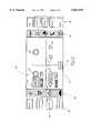
- FIG. 1illustrates a graphical user interface system 20 that is designed to be placed within a vehicle.
- a display screen 22displays a variety of information for a driver and/or passenger of a vehicle.
- An electronic controller 24controls what is shown on the display screen 22.
- the electronic controller 24is coupled to a plurality of vehicle subsystems 26. Examples of subsystems include a radio 28, a cruise control 30, the heating, ventilation and air conditioning (HVAC) system 32 and a cellular telephone 34.
- HVACheating, ventilation and air conditioning
- FIG. 1illustrates a graphical user interface system 20 that is designed to be placed within a vehicle.
- a display screen 22displays a variety of information for a driver and/or passenger of a vehicle.
- An electronic controller 24controls what is shown on the display screen 22.
- the electronic controller 24is coupled to a plurality of vehicle subsystems 26. Examples of subsystems include a radio 28, a cruise control 30, the heating, ventilation and air conditioning (HVAC) system 32 and a cellular telephone 34
- a plurality of selection switches 36enable a user to select one of the subsystems to be adjusted.
- a set of switches 38enable a user of the system to modify the operation of a selected subsystem.
- two multi-purpose adjustment switches 40 and 42are included.
- the knobs 40 and 42preferably are push-turn adjustment switches that can be pressed or rotated.
- the preferred embodimentalso includes a plurality of control switches. In the illustrated embodiment, control switches 44 and 46 are grouped as one set while control switches 48 and 50 are grouped as a second set. The grouping of the control switches provides a convenient way of having bi-directional control of a function.
- the system 20, designed according to this inventionuses a reduced number of switches and provides the significant advantage of eliminating a driver's need to navigate through a series of menus. Further, this invention allows instant activation of the vehicle subsystems at a single press of a switch.
- the specific arrangement and type of multi-purpose adjustment switches 40, 42 and control switches 44, 46, 48 and 50provides the ability to easily locate and operate the switches without distracting a driver from the task of driving the vehicle.
- the selection switches 36preferably are arrayed together alongside the display screen 22.
- the selection switches 36can be placed on an angled, hand-contoured shelf near the display or on a collar behind the steering wheel, for example.
- the selection switches, multi-purpose adjustment switches and control switchesare supported on the steering wheel for easy access.
- Each of the selection switches 36preferably is a spring-loaded rocker switch. Each switch preferably is programmed to activate a single subsystem and, therefore, is dedicated to one subsystem within the vehicle. Having dedicated selection switches 36 provides the ability to label the switches in a manner that makes them readily perceivable by a driver. If the display screen 22 is within a "no-lean reach" of a driver, it is most preferred to place the selection switches 36 along side the display screen 22 generally as illustrated.
- the spring-loaded rocker switch 52includes a labelled activation surface 54 and a deactivation surface 56 that is labeled with the word "Off.” All of the selection switches 36 preferably are programmed such that an initial press of the activation surface causes the electronic controller 24 to instantaneously display the subsystem and its adjustable functions on the display screen 22 and to activate the subsystem according to preselected default settings. Subsequent presses of the activation surface of each selection switch will recall the subsystem display to the screen 22.
- a subsystempreferably is deactivated by the first press of the deactivation surface. "Initial" press of the activation surface refers to the first time that an activation surface is pressed after the vehicle is turned on.
- FIG. 2illustrates a preferred display 58 on the screen 22 associated with the radio subsystem.
- the display screenincludes a subsystem identifier 59.
- the illustrated displayis divided into four sub-screens or quadrants. Each sub-screen is associated with one of the multi-purpose adjustment switches or a set of control switches.
- the illustrated multi-purpose adjustment switches 40' and 42'are visual representations on the display screen 22 of the actual multi-purpose adjustment switches 40 and 42, respectively.
- the control switches 44', 46', 48' and 50'are representations on the screen of the actual control switches.
- the multi-purpose adjustment switches and control switches illustrated on the display screenare arranged in the same order as the physical layout within the vehicle.
- the correspondence between the physical layout and the displayenables a user to readily associate movement of the switches with a desired adjustment to the functions of a displayed subsystem. Adjustments made by manipulating the switches preferably are displayed on the screen 22 simultaneously with the control knobs and buttons being manipulated by the driver.
- the display 58preferably includes the entire plurality of adjustable functions associated with the radio subsystem all on one screen. Those functions that can be adjusted by manipulating multi-purpose adjustment switch 40 are illustrated at 60. Similarly, those control functions that can be adjusted with multi-purpose adjustment switch 42 are illustrated at 62.
- a display portion 63shows the driver a visual representation of an adjustment being made or the current setting for a selected function.
- the control switches 48 and 50are dedicated to an adjustable function 64.
- the display portion 65visually indicates to the driver the current setting of the function 64 and, simultaneously displays any adjustments made by manipulating the control switches 48 and 50.
- the control switches 44 and 46are dedicated to an adjustable function 66.
- the display screen 22preferably includes a plurality of icons 68 and 70 that correspond to the vehicle subsystems that can be operated and adjusted through the system 20.
- the screen icons 68 and 70preferably appear whenever the display screen 22 is activated.
- An advantage provided by the screen iconsis that each icon corresponds to one of the vehicle subsystems and preferably is located on the screen adjacent to the corresponding selection switch. Further, it is most preferred that the icon corresponding to a selected subsystem be highlighted or otherwise visually distinguished on the screen relative to the remaining icons. This provides the driver an additional visual indication of the selected subsystem. For example, in FIG. 2, the icon 72 is highlighted when the electronic controller 24 recognizes that the activation surface 54 of the selection switch 52 has been pressed.
- the display 74when the activation of the selection switch 73 is pressed, the display 74 appears on the screen 22.
- the display 74includes a subsystem indicator 75, an indication of the functions 76 that are controllable by manipulating the adjustment switch 40 and an adjustable function 78 that is controllable by manipulating the control switches 48 and 50.
- the icon 79indicates that the cruise control subsystem is activated and ready to be adjusted.
- HVACheating, ventilation and air conditioning subsystem
- a plurality of functions 86 for controlling the climate on the driver side of the vehicleare adjustable using the multi-purpose adjustment switch 40.
- a plurality of functions 88 for controlling the climate on the passenger side of the vehicleare adjustable by manipulating the adjustment switch 42.
- the display 90indicates the current level of operation of the fan on the driver side of the vehicle. To increase or decrease the fan speed, the driver simply rotates the adjustment switch 40. If the driver wishes to change the temperature, she simply presses the adjustment switch 40 until the temperature function is highlighted and then rotates the adjustment switch 40 to adjust the temperature in a desired direction.
- the air conditioning function 92is dedicated to the control switches 48 and 50.
- the control switches 48 and 50may be used for increasing and decreasing adjustments of a function, in the illustrated embodiment they are used as on and off switches for subsystems such as the air conditioning.
- the control switches 44 and 46control whether the rear defogger is on or off.
- the adjustment switches 40 and 42are used to adjust and/or select a plurality of functions associated with different subsystems. For example, manipulating adjustment switch 40 adjusts the volume, balance or fade functions of the radio and the temperature, vent door positions and fan speed of the HVAC subsystem on the driver's side of the vehicle.
- the adjustment switchestherefore, are very useful in realizing a graphical user interface system designed according to this invention.
- control switches 44, 46, 48 and 50are dedicated to one function for each subsystem.
- the inventive arrangement of the switchestherefore, provides system versatility with a relatively small number of control switches knobs and/or buttons.
- a variety of display screensare available, however, the most visually satisfying displays with a large amount of versatility are achieved by using an electroluminescent display. Therefore, an electroluminescent display is preferred.
- a variety of microprocessors and microcontrollersare commercially available that will suffice for the electronic controller 24.
- the flow chart 100illustrates the basic methodology of this invention in six basic steps. Specifically, a particular subsystem is selected by a user by pressing an activation surface of one of the selection switches 36. The electronic controller 24 then displays the selected subsystem on the screen along with the entire plurality of adjustable functions associated with that subsystem. The user then utilizes the switches 38 to select one of the displayed functions. An appropriate switch is then used to adjust the selected function. The electronic controller 24 ensures that the adjustment made to the selected function is simultaneously displayed on the display screen 22. Electronic controller 24 then modifies the operation of the subsystem according to the adjustment made by the user so that the operation of the subsystem is consistent with that shown on the display screen 22. Given the above description, one skilled in the art can develop the specific code to program the controller 24 to accomplish the results achieved by a system designed according to this invention.
- the display screen 22in one embodiment, is mounted on a steering wheel 110 within the vehicle.
- the display screen 22will rotate with the wheel 110 when the steering wheel is rotated by a driver.
- a wheel position sensor 112preferably is included for determining a rotated position of the wheel. Information from the sensor 112 is processed by the electronic controller 24 and the display on the display screen 22 preferably is manipulated. Specifically, the display on the display screen 22 will be counter-rotated with rotations of the steering wheel 110 to maintain the display in an upright, readable orientation relative to the driver.
- the wheel position sensor 112determines an angle of rotation of the steering wheel 110 from a home position (illustrated in FIG. 6).
- the electronic controller 24responsively rotates the display on the display screen 22 through an angle in an opposite direction and having a magnitude proportional to the angle of rotation of the steering wheel 110.
Landscapes
- Engineering & Computer Science (AREA)
- Mechanical Engineering (AREA)
- Chemical & Material Sciences (AREA)
- Combustion & Propulsion (AREA)
- Transportation (AREA)
- Instrument Panels (AREA)
- User Interface Of Digital Computer (AREA)
Abstract
Description
Claims (19)
Priority Applications (2)
| Application Number | Priority Date | Filing Date | Title |
|---|---|---|---|
| US08/707,155US5821935A (en) | 1996-09-03 | 1996-09-03 | Graphical user interface with electronic feature access |
| PCT/US1997/014971WO1998009847A1 (en) | 1996-09-03 | 1997-08-26 | Graphical user interface with electronic feature access |
Applications Claiming Priority (1)
| Application Number | Priority Date | Filing Date | Title |
|---|---|---|---|
| US08/707,155US5821935A (en) | 1996-09-03 | 1996-09-03 | Graphical user interface with electronic feature access |
Publications (1)
| Publication Number | Publication Date |
|---|---|
| US5821935Atrue US5821935A (en) | 1998-10-13 |
Family
ID=24840566
Family Applications (1)
| Application Number | Title | Priority Date | Filing Date |
|---|---|---|---|
| US08/707,155Expired - Fee RelatedUS5821935A (en) | 1996-09-03 | 1996-09-03 | Graphical user interface with electronic feature access |
Country Status (2)
| Country | Link |
|---|---|
| US (1) | US5821935A (en) |
| WO (1) | WO1998009847A1 (en) |
Cited By (66)
| Publication number | Priority date | Publication date | Assignee | Title |
|---|---|---|---|---|
| WO1999014655A1 (en)* | 1997-09-15 | 1999-03-25 | Sony Trans Com, Inc. | Scrolling navigational display system |
| US6201540B1 (en)* | 1998-01-07 | 2001-03-13 | Microsoft Corporation | Graphical interface components for in-dash automotive accessories |
| FR2798329A1 (en)* | 1999-09-13 | 2001-03-16 | Siemens Automotive Sa | Vehicle control device associated with steering wheel has tactile surface located on central part of wheel that may operate calculator located on sideboard and screen used for indicators, telephone etc. |
| US6223103B1 (en)* | 1997-11-12 | 2001-04-24 | Lear Automotive Dearborn, Inc. | Driver display with highlighted images |
| US20010052912A1 (en)* | 2000-06-19 | 2001-12-20 | Yazaki Corporation | Multifunction switch device with display function |
| FR2813966A1 (en)* | 2000-09-12 | 2002-03-15 | Volkswagen Ag | METHOD FOR OPERATING A MENU-GUIDED MULTI-FUNCTIONAL DISPLAY DEVICE AND THE CORRESPONDING DISPLAY DEVICE |
| US6429542B1 (en)* | 1999-06-18 | 2002-08-06 | Yazaki Corporation | Multi-function switch system |
| EP1228917A1 (en) | 2001-02-01 | 2002-08-07 | Pi Technology | A control arrangement |
| US6567069B1 (en)* | 1998-11-25 | 2003-05-20 | Alliedsignal Inc. | Integrated display and yoke mechanism |
| US20030128103A1 (en)* | 2002-01-04 | 2003-07-10 | Fitzpatrick Robert C. | Multi-position display for vehicle |
| US20030167112A1 (en)* | 2002-03-01 | 2003-09-04 | Susumu Akiyama | Vehicle agent system acting for driver in controlling in-vehicle devices |
| US6640169B2 (en)* | 2001-03-21 | 2003-10-28 | Volkswagen Ag | Dynamic human-machine interface device and method |
| EP1080974A3 (en)* | 1999-09-03 | 2004-01-07 | Volkswagen Aktiengesellschaft | Display unit for a vehicle heating or airconditioning device including a screen |
| WO2004008467A1 (en)* | 2002-07-15 | 2004-01-22 | Volkswagen Aktiengesellschaft | Method for operating functional groups and/or functions, and operator device |
| US6704032B1 (en)* | 2000-10-27 | 2004-03-09 | Microsoft Corporation | Methods and arrangements for interacting with controllable objects within a graphical user interface environment using various input mechanisms |
| US20040143372A1 (en)* | 2002-11-13 | 2004-07-22 | Heiko Taxis | In-car computer system and method for selecting and activating option menus |
| US20040172182A1 (en)* | 2003-02-28 | 2004-09-02 | Pathare Prakash S. | Vehicle user interface system and method |
| US20040201284A1 (en)* | 2003-04-09 | 2004-10-14 | Mccullough Scott A. | Method, programming interface and mechanism for changing vehicle personalization settings/features |
| US20040207607A1 (en)* | 2003-04-15 | 2004-10-21 | Will Specks | Operating element having an integrated display element, and a method for command output using an operating element |
| US20050014478A1 (en)* | 2003-07-14 | 2005-01-20 | Visteon Global Technologies, Inc. | Radio human-machine interface using knobs and menu picks |
| US20050021190A1 (en)* | 2003-07-24 | 2005-01-27 | Worrell Barry C. | Method and apparatus for accessing vehicle systems |
| US20050076308A1 (en)* | 2003-10-01 | 2005-04-07 | Mansell Wayne T. | Control system with customizable menu structure for personal mobility vehicle |
| US20050197745A1 (en)* | 2004-03-04 | 2005-09-08 | Davis Alan C. | Vehicle information system with remote communicator |
| EP1055544A3 (en)* | 1999-05-27 | 2005-12-21 | CLARION Co., Ltd. | In-car switch controller |
| US20060020376A1 (en)* | 2004-01-06 | 2006-01-26 | Isao Kanno | Display device for watercraft |
| US20060070795A1 (en)* | 2003-04-04 | 2006-04-06 | Takata-Petri Ag | Steering wheel for motor vehicles |
| US20060146074A1 (en)* | 2004-12-31 | 2006-07-06 | Harrison Edward R | Display for rotatable steering device |
| US20060155431A1 (en)* | 2004-03-04 | 2006-07-13 | Berg Frederick J | Vehicle information system with remote communicator |
| USD528549S1 (en)* | 2005-04-11 | 2006-09-19 | Microsoft Corporation | Transitional image for a portion of a display screen |
| USD529035S1 (en)* | 2005-04-11 | 2006-09-26 | Microsoft Corporation | Image for a portion of a display screen |
| USD529506S1 (en)* | 2005-04-11 | 2006-10-03 | Microsoft Corporation | Image for a portion of a display screen |
| US20060276940A1 (en)* | 2005-06-01 | 2006-12-07 | Berg Frederick J | Vehicle information system with remote communicators in a network environment |
| US20060286944A1 (en)* | 2005-06-06 | 2006-12-21 | Songwe Jr N | Vehicle information/control system |
| US20070008305A1 (en)* | 2005-06-28 | 2007-01-11 | Visteon Global Technologies, Inc. | Multiple function radio bezel interface |
| US20070032913A1 (en)* | 2005-08-04 | 2007-02-08 | Ghoneim Youssef A | Method and system for dynamic automotive vehicle moding |
| US20070069914A1 (en)* | 2004-07-26 | 2007-03-29 | Gm Global Technology Operations, Inc. | Multifunction control system |
| US20070069880A1 (en)* | 2005-09-29 | 2007-03-29 | Best Steven F | Customizing the layout of the instrument panel of a motorized vehicle |
| US20070227795A1 (en)* | 2003-09-18 | 2007-10-04 | Daimlerchrysler Ag | Operating and Display Unit |
| USD553577S1 (en)* | 2004-05-17 | 2007-10-23 | Dynamic Controls Limited | Electronic vehicle controller |
| US20080028339A1 (en)* | 2003-12-23 | 2008-01-31 | Daimlerchrysler | Control System for a Motor Vehicle |
| US20080023254A1 (en)* | 2005-01-19 | 2008-01-31 | Takata-Petri Ag | Steering wheel assembly for a motor vehicle |
| DE102006035171A1 (en)* | 2006-07-29 | 2008-01-31 | Daimler Ag | Steering wheel operating system for e.g. lorry, has display instrument with panel switching from information mode into pop-up-window mode in reaction to manipulation of key, where pop up window is assigned to key |
| US20080125936A1 (en)* | 2006-11-29 | 2008-05-29 | Giga-Byte Technology Co., Ltd. | Method for Controlling Car Computer and Apparatus Thereof |
| WO2008108751A3 (en)* | 2007-03-02 | 2008-11-20 | Volvo Trucks North America Inc | Control module for controlling vehicular systems having different communication protocols |
| US20080301587A1 (en)* | 2003-12-23 | 2008-12-04 | Daimlerchrysler Ag | Control System for a Motor Vehicle |
| US20090192677A1 (en)* | 2007-11-13 | 2009-07-30 | Tk Holdings Inc. | Vehicle communication system and method |
| US20090192795A1 (en)* | 2007-11-13 | 2009-07-30 | Tk Holdings Inc. | System and method for receiving audible input in a vehicle |
| US20090319095A1 (en)* | 2008-06-20 | 2009-12-24 | Tk Holdings Inc. | Vehicle driver messaging system and method |
| DE102008041625A1 (en)* | 2008-08-27 | 2010-03-04 | Faurecia Innenraum Systeme Gmbh | Operating element for a display device in a means of transport |
| US20100107121A1 (en)* | 2007-07-17 | 2010-04-29 | Toyota Jidosha Kabushiki Kaisha | Operation apparatus |
| DE102008050921A1 (en) | 2008-10-10 | 2010-06-24 | Ford-Werke Gmbh | Indicating- and control- device for use in motor vehicle, has input keypad provided with input keys and placed on control panel to input data such that data in input field is represented on display panel |
| DE102006055532B4 (en)* | 2006-11-24 | 2011-07-07 | MAN Truck & Bus AG, 80995 | Dimensional representation of the function keys of a steering wheel in the instrument panel of the motor vehicle |
| US8001488B1 (en)* | 2002-05-31 | 2011-08-16 | Hewlett-Packard Development Company, L.P. | User interface dial with display |
| DE102010012240A1 (en)* | 2010-03-22 | 2011-09-22 | Volkswagen Ag | Operating and display device for motor car, has common display area for representation of function groups, where selected functions are displayed in display area during approximation of operating unit and/or contact of operating controllers |
| USD696679S1 (en)* | 2011-06-15 | 2013-12-31 | Samsung Electronics Co., Ltd. | Display screen or portion thereof with a graphical user interface |
| US20150286385A1 (en)* | 2012-10-11 | 2015-10-08 | Lg Electronics Inc. | Display device mounted on steering wheel of vehicle and control method thereof |
| US9164619B2 (en)* | 2014-03-04 | 2015-10-20 | Panasonic Automotive Systems Company Of America, Division Of Panasonic Corporation Of North America | Configurable touch screen LCD steering wheel controls |
| US20150360711A1 (en)* | 2013-01-31 | 2015-12-17 | Daimler Ag | Steering Wheel with Data Transmission via a Finger Navigation Module |
| US20160039457A1 (en)* | 2013-04-11 | 2016-02-11 | Zf Friedrichshafen Ag | Display device and method for displaying data and driver assistance system for a vehicle |
| US20160046323A1 (en)* | 2013-04-11 | 2016-02-18 | Zf Friedrichshafen Ag | Sensor device and method for determining a steering angle of a vehicle and driver assistance system for a vehicle |
| US9628705B2 (en) | 2011-11-14 | 2017-04-18 | Nvidia Corporation | Navigation device |
| US10144383B2 (en) | 2016-09-29 | 2018-12-04 | Steering Solutions Ip Holding Corporation | Steering wheel with video screen and airbag |
| US10322682B2 (en) | 2016-03-03 | 2019-06-18 | Steering Solutions Ip Holding Corporation | Steering wheel with keyboard |
| US11435862B2 (en)* | 2018-10-15 | 2022-09-06 | Mitsubishi Electric Corporation | Touch panel input device, touch panel input method, and recording medium |
| US11912178B2 (en) | 2022-06-17 | 2024-02-27 | Morteza Vadipour | System for transforming the interior of a vehicle into a sleeping or load space |
| US20240408962A1 (en)* | 2023-06-07 | 2024-12-12 | Dr. Ing. H. C. F. Porsche Ag | Steering apparatus for a motor vehicle |
Families Citing this family (6)
| Publication number | Priority date | Publication date | Assignee | Title |
|---|---|---|---|---|
| CN100347005C (en)* | 1998-10-15 | 2007-11-07 | 大众汽车有限公司 | Multifunctional display and control device in automobile and control method thereof |
| DE19943579A1 (en)* | 1999-09-13 | 2000-11-02 | Bayerische Motoren Werke Ag | Multifunction control device for a motor vehicle |
| DE19947504B4 (en)* | 1999-10-01 | 2004-06-03 | Robert Bosch Gmbh | Circuit arrangement for a motor vehicle cockpit |
| NO20020896L (en)* | 2001-10-02 | 2003-04-03 | Ziad Badarneh | Interactive system |
| DE102007051013A1 (en) | 2007-10-25 | 2009-04-30 | Bayerische Motoren Werke Aktiengesellschaft | Method for operating a dialogue system for a motor vehicle |
| DE102010012239B4 (en)* | 2010-03-22 | 2023-11-30 | Volkswagen Ag | Operating and display device for a motor vehicle |
Citations (6)
| Publication number | Priority date | Publication date | Assignee | Title |
|---|---|---|---|---|
| US4792783A (en)* | 1986-05-07 | 1988-12-20 | Electro-Mechanical Products | Vehicular function controller having alterable function designators |
| US5270689A (en)* | 1988-10-27 | 1993-12-14 | Baverische Motoren Werke Ag | Multi-function operating device |
| DE4338171C1 (en)* | 1993-11-09 | 1995-04-20 | Daimler Benz Ag | Keyboard and display system |
| DE29604717U1 (en)* | 1996-03-14 | 1996-05-30 | Moeller, Jens-Ulrich, 35581 Wetzlar | Operating complex for electrical / electronic automotive equipment |
| US5539429A (en)* | 1989-10-24 | 1996-07-23 | Mitsubishi Denki Kabushiki Kaisha | Touch device panel |
| US5666102A (en)* | 1996-07-24 | 1997-09-09 | United Technologies Automotive Systems, Inc. | Vehicle signals incorporated into steering wheel rim |
Family Cites Families (3)
| Publication number | Priority date | Publication date | Assignee | Title |
|---|---|---|---|---|
| US5017916A (en)* | 1989-03-09 | 1991-05-21 | Navistar International Transportation Corp. | Shift prompter/driver information display |
| DE4130993C1 (en)* | 1991-09-18 | 1993-02-18 | Adam Opel Ag, 6090 Ruesselsheim, De | |
| DE4328564C1 (en)* | 1993-08-25 | 1994-08-25 | Daimler Benz Ag | Steering wheel for a motor vehicle |
- 1996
- 1996-09-03USUS08/707,155patent/US5821935A/ennot_activeExpired - Fee Related
- 1997
- 1997-08-26WOPCT/US1997/014971patent/WO1998009847A1/enactiveApplication Filing
Patent Citations (6)
| Publication number | Priority date | Publication date | Assignee | Title |
|---|---|---|---|---|
| US4792783A (en)* | 1986-05-07 | 1988-12-20 | Electro-Mechanical Products | Vehicular function controller having alterable function designators |
| US5270689A (en)* | 1988-10-27 | 1993-12-14 | Baverische Motoren Werke Ag | Multi-function operating device |
| US5539429A (en)* | 1989-10-24 | 1996-07-23 | Mitsubishi Denki Kabushiki Kaisha | Touch device panel |
| DE4338171C1 (en)* | 1993-11-09 | 1995-04-20 | Daimler Benz Ag | Keyboard and display system |
| DE29604717U1 (en)* | 1996-03-14 | 1996-05-30 | Moeller, Jens-Ulrich, 35581 Wetzlar | Operating complex for electrical / electronic automotive equipment |
| US5666102A (en)* | 1996-07-24 | 1997-09-09 | United Technologies Automotive Systems, Inc. | Vehicle signals incorporated into steering wheel rim |
Non-Patent Citations (2)
| Title |
|---|
| Yamaha PSR 520 Owner s Manual, Yamaha Corp., 1995 pp. 4 5, 10 14, 33 34.* |
| Yamaha PSR-520 Owner's Manual, Yamaha Corp., 1995 pp. 4-5, 10-14, 33-34. |
Cited By (95)
| Publication number | Priority date | Publication date | Assignee | Title |
|---|---|---|---|---|
| US6034688A (en)* | 1997-09-15 | 2000-03-07 | Sony Corporation | Scrolling navigational display system |
| WO1999014655A1 (en)* | 1997-09-15 | 1999-03-25 | Sony Trans Com, Inc. | Scrolling navigational display system |
| US6223103B1 (en)* | 1997-11-12 | 2001-04-24 | Lear Automotive Dearborn, Inc. | Driver display with highlighted images |
| US6201540B1 (en)* | 1998-01-07 | 2001-03-13 | Microsoft Corporation | Graphical interface components for in-dash automotive accessories |
| US6567069B1 (en)* | 1998-11-25 | 2003-05-20 | Alliedsignal Inc. | Integrated display and yoke mechanism |
| EP1055544A3 (en)* | 1999-05-27 | 2005-12-21 | CLARION Co., Ltd. | In-car switch controller |
| EP1785308A3 (en)* | 1999-05-27 | 2007-05-30 | Clarion Co., Ltd. | In-car switch controller |
| US6429542B1 (en)* | 1999-06-18 | 2002-08-06 | Yazaki Corporation | Multi-function switch system |
| EP1080974A3 (en)* | 1999-09-03 | 2004-01-07 | Volkswagen Aktiengesellschaft | Display unit for a vehicle heating or airconditioning device including a screen |
| FR2798329A1 (en)* | 1999-09-13 | 2001-03-16 | Siemens Automotive Sa | Vehicle control device associated with steering wheel has tactile surface located on central part of wheel that may operate calculator located on sideboard and screen used for indicators, telephone etc. |
| US20010052912A1 (en)* | 2000-06-19 | 2001-12-20 | Yazaki Corporation | Multifunction switch device with display function |
| FR2813966A1 (en)* | 2000-09-12 | 2002-03-15 | Volkswagen Ag | METHOD FOR OPERATING A MENU-GUIDED MULTI-FUNCTIONAL DISPLAY DEVICE AND THE CORRESPONDING DISPLAY DEVICE |
| US6704032B1 (en)* | 2000-10-27 | 2004-03-09 | Microsoft Corporation | Methods and arrangements for interacting with controllable objects within a graphical user interface environment using various input mechanisms |
| EP1228917A1 (en) | 2001-02-01 | 2002-08-07 | Pi Technology | A control arrangement |
| US6640169B2 (en)* | 2001-03-21 | 2003-10-28 | Volkswagen Ag | Dynamic human-machine interface device and method |
| US20030128103A1 (en)* | 2002-01-04 | 2003-07-10 | Fitzpatrick Robert C. | Multi-position display for vehicle |
| US6853896B2 (en)* | 2002-03-01 | 2005-02-08 | Denso Corporation | Vehicle agent system acting for driver in controlling in-vehicle devices |
| US20030167112A1 (en)* | 2002-03-01 | 2003-09-04 | Susumu Akiyama | Vehicle agent system acting for driver in controlling in-vehicle devices |
| US8001488B1 (en)* | 2002-05-31 | 2011-08-16 | Hewlett-Packard Development Company, L.P. | User interface dial with display |
| WO2004008467A1 (en)* | 2002-07-15 | 2004-01-22 | Volkswagen Aktiengesellschaft | Method for operating functional groups and/or functions, and operator device |
| US20040143372A1 (en)* | 2002-11-13 | 2004-07-22 | Heiko Taxis | In-car computer system and method for selecting and activating option menus |
| US7035720B2 (en)* | 2002-11-13 | 2006-04-25 | Harman / Becker Automotive Systems Gmbh | In-car computer system and method for selecting and activating option menus |
| US20040172182A1 (en)* | 2003-02-28 | 2004-09-02 | Pathare Prakash S. | Vehicle user interface system and method |
| US6842677B2 (en) | 2003-02-28 | 2005-01-11 | Prakash S. Pathare | Vehicle user interface system and method |
| US7414520B2 (en)* | 2003-04-04 | 2008-08-19 | Takata-Petri Ag | Steering wheel for motor vehicles |
| US20060070795A1 (en)* | 2003-04-04 | 2006-04-06 | Takata-Petri Ag | Steering wheel for motor vehicles |
| US20040201284A1 (en)* | 2003-04-09 | 2004-10-14 | Mccullough Scott A. | Method, programming interface and mechanism for changing vehicle personalization settings/features |
| US7112894B2 (en)* | 2003-04-09 | 2006-09-26 | General Motors Corporation | Method, programming interface and mechanism for changing vehicle personalization settings/features |
| US20040207607A1 (en)* | 2003-04-15 | 2004-10-21 | Will Specks | Operating element having an integrated display element, and a method for command output using an operating element |
| US20050014478A1 (en)* | 2003-07-14 | 2005-01-20 | Visteon Global Technologies, Inc. | Radio human-machine interface using knobs and menu picks |
| US7233779B2 (en)* | 2003-07-14 | 2007-06-19 | Visteon Global Technologies, Inc. | Radio human-machine interface using knobs and menu picks |
| US20050021190A1 (en)* | 2003-07-24 | 2005-01-27 | Worrell Barry C. | Method and apparatus for accessing vehicle systems |
| US20070227795A1 (en)* | 2003-09-18 | 2007-10-04 | Daimlerchrysler Ag | Operating and Display Unit |
| US20050076308A1 (en)* | 2003-10-01 | 2005-04-07 | Mansell Wayne T. | Control system with customizable menu structure for personal mobility vehicle |
| US7159181B2 (en) | 2003-10-01 | 2007-01-02 | Sunrise Medical Hhg Inc. | Control system with customizable menu structure for personal mobility vehicle |
| US20080028339A1 (en)* | 2003-12-23 | 2008-01-31 | Daimlerchrysler | Control System for a Motor Vehicle |
| US20080301587A1 (en)* | 2003-12-23 | 2008-12-04 | Daimlerchrysler Ag | Control System for a Motor Vehicle |
| US20060020376A1 (en)* | 2004-01-06 | 2006-01-26 | Isao Kanno | Display device for watercraft |
| US7571032B2 (en)* | 2004-01-06 | 2009-08-04 | Yamaha Hatsudoki Kabushiki Kaisha | Display device for watercraft |
| US20050197745A1 (en)* | 2004-03-04 | 2005-09-08 | Davis Alan C. | Vehicle information system with remote communicator |
| US20060155431A1 (en)* | 2004-03-04 | 2006-07-13 | Berg Frederick J | Vehicle information system with remote communicator |
| USD553577S1 (en)* | 2004-05-17 | 2007-10-23 | Dynamic Controls Limited | Electronic vehicle controller |
| US20070069914A1 (en)* | 2004-07-26 | 2007-03-29 | Gm Global Technology Operations, Inc. | Multifunction control system |
| US7340333B2 (en)* | 2004-07-26 | 2008-03-04 | Gm Global Technology Operations, Inc. | Multifunction control system |
| US20060146074A1 (en)* | 2004-12-31 | 2006-07-06 | Harrison Edward R | Display for rotatable steering device |
| US7602278B2 (en)* | 2005-01-19 | 2009-10-13 | Takata-Petri Ag | Steering wheel assembly for a motor vehicle |
| US7605694B2 (en) | 2005-01-19 | 2009-10-20 | Takata-Petri Ag | Steering wheel assembly for a motor vehicle |
| US20080023253A1 (en)* | 2005-01-19 | 2008-01-31 | Takata-Petri Ag | Steering wheel assembly for a motor vehicle |
| US20080023254A1 (en)* | 2005-01-19 | 2008-01-31 | Takata-Petri Ag | Steering wheel assembly for a motor vehicle |
| USD528549S1 (en)* | 2005-04-11 | 2006-09-19 | Microsoft Corporation | Transitional image for a portion of a display screen |
| USD529035S1 (en)* | 2005-04-11 | 2006-09-26 | Microsoft Corporation | Image for a portion of a display screen |
| USD529506S1 (en)* | 2005-04-11 | 2006-10-03 | Microsoft Corporation | Image for a portion of a display screen |
| US20060276940A1 (en)* | 2005-06-01 | 2006-12-07 | Berg Frederick J | Vehicle information system with remote communicators in a network environment |
| US7593792B2 (en) | 2005-06-01 | 2009-09-22 | Delphi Technologies, Inc. | Vehicle information system with remote communicators in a network environment |
| US20060286944A1 (en)* | 2005-06-06 | 2006-12-21 | Songwe Jr N | Vehicle information/control system |
| US7474204B2 (en)* | 2005-06-06 | 2009-01-06 | Joneso Design & Consulting, Inc. | Vehicle information/control system |
| US20090108617A1 (en)* | 2005-06-06 | 2009-04-30 | Joneso Design & Consulting, Inc. | Vehicle Information/Control System |
| US20070008305A1 (en)* | 2005-06-28 | 2007-01-11 | Visteon Global Technologies, Inc. | Multiple function radio bezel interface |
| US20070032913A1 (en)* | 2005-08-04 | 2007-02-08 | Ghoneim Youssef A | Method and system for dynamic automotive vehicle moding |
| US20070069880A1 (en)* | 2005-09-29 | 2007-03-29 | Best Steven F | Customizing the layout of the instrument panel of a motorized vehicle |
| DE102006035171A1 (en)* | 2006-07-29 | 2008-01-31 | Daimler Ag | Steering wheel operating system for e.g. lorry, has display instrument with panel switching from information mode into pop-up-window mode in reaction to manipulation of key, where pop up window is assigned to key |
| DE102006055532B4 (en)* | 2006-11-24 | 2011-07-07 | MAN Truck & Bus AG, 80995 | Dimensional representation of the function keys of a steering wheel in the instrument panel of the motor vehicle |
| US20080125936A1 (en)* | 2006-11-29 | 2008-05-29 | Giga-Byte Technology Co., Ltd. | Method for Controlling Car Computer and Apparatus Thereof |
| WO2008108751A3 (en)* | 2007-03-02 | 2008-11-20 | Volvo Trucks North America Inc | Control module for controlling vehicular systems having different communication protocols |
| US20100107121A1 (en)* | 2007-07-17 | 2010-04-29 | Toyota Jidosha Kabushiki Kaisha | Operation apparatus |
| US9102244B2 (en)* | 2007-07-17 | 2015-08-11 | Toyota Jidosha Kabushiki Kaisha | Operation apparatus |
| US20090192795A1 (en)* | 2007-11-13 | 2009-07-30 | Tk Holdings Inc. | System and method for receiving audible input in a vehicle |
| US20090192677A1 (en)* | 2007-11-13 | 2009-07-30 | Tk Holdings Inc. | Vehicle communication system and method |
| US9302630B2 (en) | 2007-11-13 | 2016-04-05 | Tk Holdings Inc. | System and method for receiving audible input in a vehicle |
| US8296012B2 (en) | 2007-11-13 | 2012-10-23 | Tk Holdings Inc. | Vehicle communication system and method |
| US20090319095A1 (en)* | 2008-06-20 | 2009-12-24 | Tk Holdings Inc. | Vehicle driver messaging system and method |
| US9520061B2 (en)* | 2008-06-20 | 2016-12-13 | Tk Holdings Inc. | Vehicle driver messaging system and method |
| DE102008041625A1 (en)* | 2008-08-27 | 2010-03-04 | Faurecia Innenraum Systeme Gmbh | Operating element for a display device in a means of transport |
| DE102008041625B4 (en)* | 2008-08-27 | 2013-07-18 | Faurecia Innenraum Systeme Gmbh | Control element for a display device in a means of transport and center console of a motor vehicle and method for operating a control element for a display device and computer program product |
| US20100259483A1 (en)* | 2008-10-10 | 2010-10-14 | Ford Global Technologies, Llc | Operating and display system for a vehicle |
| DE102008050921A1 (en) | 2008-10-10 | 2010-06-24 | Ford-Werke Gmbh | Indicating- and control- device for use in motor vehicle, has input keypad provided with input keys and placed on control panel to input data such that data in input field is represented on display panel |
| DE102010012240A1 (en)* | 2010-03-22 | 2011-09-22 | Volkswagen Ag | Operating and display device for motor car, has common display area for representation of function groups, where selected functions are displayed in display area during approximation of operating unit and/or contact of operating controllers |
| USD696679S1 (en)* | 2011-06-15 | 2013-12-31 | Samsung Electronics Co., Ltd. | Display screen or portion thereof with a graphical user interface |
| US9628705B2 (en) | 2011-11-14 | 2017-04-18 | Nvidia Corporation | Navigation device |
| US20150286385A1 (en)* | 2012-10-11 | 2015-10-08 | Lg Electronics Inc. | Display device mounted on steering wheel of vehicle and control method thereof |
| US9552148B2 (en)* | 2012-10-11 | 2017-01-24 | Lg Electronics Inc. | Display device mounted on steering wheel of vehicle and control method thereof |
| US9878731B2 (en)* | 2013-01-31 | 2018-01-30 | Daimler Ag | Steering wheel with data transmission via a finger navigation module |
| US20150360711A1 (en)* | 2013-01-31 | 2015-12-17 | Daimler Ag | Steering Wheel with Data Transmission via a Finger Navigation Module |
| US9637169B2 (en)* | 2013-04-11 | 2017-05-02 | Zf Friedrichshafen Ag | Display device and method for displaying data and driver assistance system for a vehicle |
| US20160039457A1 (en)* | 2013-04-11 | 2016-02-11 | Zf Friedrichshafen Ag | Display device and method for displaying data and driver assistance system for a vehicle |
| US9656689B2 (en)* | 2013-04-11 | 2017-05-23 | Zf Friedrichshafen Ag | Sensor device and method for determining a steering angle of a vehicle and driver assistance system for a vehicle |
| US20160046323A1 (en)* | 2013-04-11 | 2016-02-18 | Zf Friedrichshafen Ag | Sensor device and method for determining a steering angle of a vehicle and driver assistance system for a vehicle |
| US9557851B2 (en)* | 2014-03-04 | 2017-01-31 | Panasonic Automotive Systems Company Of America, Division Of Panasonic Corporation Of North America | Configurable touch screen LCD steering wheel controls |
| US20160004383A1 (en)* | 2014-03-04 | 2016-01-07 | Panasonic Automotive Systems Company Of America, Division Of Panasonic Corporation Of North America | Configurable touch screen lcd steering wheel controls |
| US9164619B2 (en)* | 2014-03-04 | 2015-10-20 | Panasonic Automotive Systems Company Of America, Division Of Panasonic Corporation Of North America | Configurable touch screen LCD steering wheel controls |
| US10322682B2 (en) | 2016-03-03 | 2019-06-18 | Steering Solutions Ip Holding Corporation | Steering wheel with keyboard |
| US10144383B2 (en) | 2016-09-29 | 2018-12-04 | Steering Solutions Ip Holding Corporation | Steering wheel with video screen and airbag |
| US11435862B2 (en)* | 2018-10-15 | 2022-09-06 | Mitsubishi Electric Corporation | Touch panel input device, touch panel input method, and recording medium |
| US11912178B2 (en) | 2022-06-17 | 2024-02-27 | Morteza Vadipour | System for transforming the interior of a vehicle into a sleeping or load space |
| US20240408962A1 (en)* | 2023-06-07 | 2024-12-12 | Dr. Ing. H. C. F. Porsche Ag | Steering apparatus for a motor vehicle |
Also Published As
| Publication number | Publication date |
|---|---|
| WO1998009847A1 (en) | 1998-03-12 |
Similar Documents
| Publication | Publication Date | Title |
|---|---|---|
| US5821935A (en) | Graphical user interface with electronic feature access | |
| US5916288A (en) | Multi-functional control switch arrangement | |
| US5847704A (en) | Method of controlling an electronically generated visual display | |
| US6157372A (en) | Method and apparatus for controlling a plurality of controllable devices | |
| US6348772B1 (en) | Control device | |
| US6411877B2 (en) | Automobile multifunctional display and control device method | |
| EP1569073B1 (en) | Single knob multifunction controller and display unit | |
| US9283829B2 (en) | Process and device for displaying different information for driver and passenger of a vehicle | |
| US5555502A (en) | Display and control apparatus for the electronic systems of a motor vehicle | |
| US10303339B2 (en) | Multi-information display software switch strategy | |
| US8041460B2 (en) | User interface for adjusting parameters for climate control systems in motor vehicles | |
| US6563492B1 (en) | Multi-function switch unit and function indicating method of the same | |
| EP2165865B1 (en) | An automotive user interface for a ventilation or airconditioning system of a road vehicle | |
| EP2572261B1 (en) | Control dial method and apparatus | |
| US20100188349A1 (en) | Control panels for onboard instruments | |
| US20170255280A1 (en) | SmartKnob | |
| US20130015964A1 (en) | Motor vehicle | |
| US6223103B1 (en) | Driver display with highlighted images | |
| JP2013528137A (en) | Vehicle display device | |
| JP7559944B2 (en) | Display control device and display control method | |
| US20100327070A1 (en) | Touch sensitive interface for heating or air conditioning a vehicle, and method for adjusting same | |
| CN102712233B (en) | Operating unit for an air conditioning device | |
| CN1855019A (en) | Apparatus for controlling electronic devices, especially in the traffic tools | |
| US11474669B2 (en) | Operating unit and method of setting a parameter of a functional unit of a motor vehicle | |
| JP2002539010A (en) | Operation device |
Legal Events
| Date | Code | Title | Description |
|---|---|---|---|
| AS | Assignment | Owner name:UNITED TECHNOLOGIES AUTOMOTIVE, INC., MICHIGAN Free format text:ASSIGNMENT OF ASSIGNORS INTEREST;ASSIGNORS:HARTMAN, HOLLISTER A.;NG, JEROME GO;REEL/FRAME:008212/0705 Effective date:19960925 | |
| AS | Assignment | Owner name:UT AUTOMOTIVE DEARBORN, INC., MICHIGAN Free format text:ASSIGNMENT OF ASSIGNORS INTEREST;ASSIGNOR:UNITED TECHNOLOGIES AUTOMOTIVE, INC.;REEL/FRAME:009083/0924 Effective date:19980330 | |
| FEPP | Fee payment procedure | Free format text:PAYOR NUMBER ASSIGNED (ORIGINAL EVENT CODE: ASPN); ENTITY STATUS OF PATENT OWNER: LARGE ENTITY | |
| FPAY | Fee payment | Year of fee payment:4 | |
| REMI | Maintenance fee reminder mailed | ||
| AS | Assignment | Owner name:LEAR CORPORATION EEDS AND INTERIORS, MICHIGAN Free format text:CHANGE OF NAME;ASSIGNOR:UNITED TECHNOLOGIES AUTOMOTIVE, INC.;REEL/FRAME:014172/0760 Effective date:19990504 | |
| FPAY | Fee payment | Year of fee payment:8 | |
| AS | Assignment | Owner name:JPMORGAN CHASE BANK, N.A., AS GENERAL ADMINISTRATI Free format text:SECURITY AGREEMENT;ASSIGNOR:LEAR CORPORATION EEDS AND INTERIORS;REEL/FRAME:017833/0198 Effective date:20060425 | |
| AS | Assignment | Owner name:LEAR AUTOMOTIVE DEARBORN, INC., MICHIGAN Free format text:CHANGE OF NAME;ASSIGNOR:UT AUTOMOTIVE DEARBORN, INC.;REEL/FRAME:018816/0718 Effective date:19990617 | |
| AS | Assignment | Owner name:JPMORGAN CHASE BANK, N.A., AS ADMINISTRATIVE AGENT Free format text:GRANT OF FIRST LIEN SECURITY INTEREST IN PATENT RIGHTS;ASSIGNOR:LEAR CORPORATION EEDS AND INTERIORS;REEL/FRAME:023525/0086 Effective date:20091109 Owner name:JPMORGAN CHASE BANK, N.A., AS ADMINISTRATIVE AGENT Free format text:GRANT OF SECOND LIEN SECURITY INTEREST IN PATENT RIGHTS;ASSIGNOR:LEAR CORPORATION EEDS AND INTERIORS;REEL/FRAME:023525/0095 Effective date:20091109 | |
| REMI | Maintenance fee reminder mailed | ||
| LAPS | Lapse for failure to pay maintenance fees | ||
| STCH | Information on status: patent discontinuation | Free format text:PATENT EXPIRED DUE TO NONPAYMENT OF MAINTENANCE FEES UNDER 37 CFR 1.362 | |
| FP | Lapsed due to failure to pay maintenance fee | Effective date:20101013 | |
| AS | Assignment | Owner name:LEAR CORPORATION EEDS AND INTERIORS, MICHIGAN Free format text:RELEASE BY SECURED PARTY;ASSIGNOR:JPMORGAN CHASE BANK, N.A.;REEL/FRAME:032699/0345 Effective date:20100830 Owner name:LEAR CORPORATION EEDS AND INTERIORS, MICHIGAN Free format text:RELEASE BY SECURED PARTY;ASSIGNOR:JPMORGAN CHASE BANK, N.A.;REEL/FRAME:032699/0604 Effective date:20100830 | |
| AS | Assignment | Owner name:LEAR CORPORATION EEDS AND INTERIORS, MICHIGAN Free format text:RELEASE BY SECURED PARTY;ASSIGNOR:JPMORGAN CHASE BANK, N.A., AS AGENT;REEL/FRAME:037670/0312 Effective date:20160104 Owner name:LEAR CORPORATION EEDS AND INTERIORS, MICHIGAN Free format text:RELEASE BY SECURED PARTY;ASSIGNOR:JPMORGAN CHASE BANK, N.A., AS AGENT;REEL/FRAME:037670/0270 Effective date:20160104 Owner name:LEAR CORPORATION EEDS AND INTERIORS, MICHIGAN Free format text:RELEASE BY SECURED PARTY;ASSIGNOR:JPMORGAN CHASE BANK, N.A., AS AGENT;REEL/FRAME:037670/0291 Effective date:20160104 |