US5821920A - Control input device for interfacing an elongated flexible object with a computer system - Google Patents
Control input device for interfacing an elongated flexible object with a computer systemDownload PDFInfo
- Publication number
- US5821920A US5821920AUS08/825,412US82541297AUS5821920AUS 5821920 AUS5821920 AUS 5821920AUS 82541297 AUS82541297 AUS 82541297AUS 5821920 AUS5821920 AUS 5821920A
- Authority
- US
- United States
- Prior art keywords
- receiving portion
- elongated flexible
- input device
- control input
- recited
- Prior art date
- Legal status (The legal status is an assumption and is not a legal conclusion. Google has not performed a legal analysis and makes no representation as to the accuracy of the status listed.)
- Expired - Lifetime
Links
- 230000033001locomotionEffects0.000claimsabstractdescription79
- 238000013519translationMethods0.000claimsdescription95
- 238000004088simulationMethods0.000claimsdescription20
- 230000004044responseEffects0.000claimsdescription14
- 230000003287optical effectEffects0.000claimsdescription13
- 238000012545processingMethods0.000claimsdescription12
- 230000007246mechanismEffects0.000claimsdescription11
- 230000003993interactionEffects0.000claimsdescription5
- 230000035807sensationEffects0.000claimsdescription4
- 210000001367arteryAnatomy0.000claimsdescription2
- 210000003462veinAnatomy0.000claimsdescription2
- 230000008878couplingEffects0.000claims1
- 238000010168coupling processMethods0.000claims1
- 238000005859coupling reactionMethods0.000claims1
- 210000000056organAnatomy0.000claims1
- 230000002792vascularEffects0.000claims1
- 238000000034methodMethods0.000description20
- 239000000463materialSubstances0.000description9
- 238000007654immersionMethods0.000description7
- 239000000523sampleSubstances0.000description6
- 230000000694effectsEffects0.000description4
- 238000003780insertionMethods0.000description4
- 230000037431insertionEffects0.000description4
- 239000000126substanceSubstances0.000description4
- 230000004888barrier functionEffects0.000description3
- 239000004033plasticSubstances0.000description3
- 230000001953sensory effectEffects0.000description3
- 238000012549trainingMethods0.000description3
- 241000699666Mus <mouse, genus>Species0.000description2
- 241001422033ThestylusSpecies0.000description2
- 239000006096absorbing agentSubstances0.000description2
- XAGFODPZIPBFFR-UHFFFAOYSA-NaluminiumChemical compound[Al]XAGFODPZIPBFFR-UHFFFAOYSA-N0.000description2
- 229910052782aluminiumInorganic materials0.000description2
- 238000005094computer simulationMethods0.000description2
- 238000010276constructionMethods0.000description2
- 230000006378damageEffects0.000description2
- 230000006870functionEffects0.000description2
- 239000003562lightweight materialSubstances0.000description2
- 239000006249magnetic particleSubstances0.000description2
- 238000012986modificationMethods0.000description2
- 230000004048modificationEffects0.000description2
- 238000012216screeningMethods0.000description2
- 230000035939shockEffects0.000description2
- 230000002463transducing effectEffects0.000description2
- 230000000007visual effectEffects0.000description2
- MFRCZYUUKMFJQJ-UHFFFAOYSA-N1,4-dioxane-2,5-dione;1,3-dioxan-2-oneChemical compoundO=C1OCCCO1.O=C1COC(=O)CO1MFRCZYUUKMFJQJ-UHFFFAOYSA-N0.000description1
- 241000699670Mus sp.Species0.000description1
- XUIMIQQOPSSXEZ-UHFFFAOYSA-NSiliconChemical compound[Si]XUIMIQQOPSSXEZ-UHFFFAOYSA-N0.000description1
- 238000004026adhesive bondingMethods0.000description1
- 230000036592analgesiaEffects0.000description1
- 230000015572biosynthetic processEffects0.000description1
- 238000005520cutting processMethods0.000description1
- 238000013461designMethods0.000description1
- 238000002059diagnostic imagingMethods0.000description1
- 239000003814drugSubstances0.000description1
- 230000007613environmental effectEffects0.000description1
- 239000000835fiberSubstances0.000description1
- 238000002357laparoscopic surgeryMethods0.000description1
- 238000004519manufacturing processMethods0.000description1
- 229910052710siliconInorganic materials0.000description1
- 239000010703siliconSubstances0.000description1
- 229910001220stainless steelInorganic materials0.000description1
- 239000010935stainless steelSubstances0.000description1
- 230000000451tissue damageEffects0.000description1
- 231100000827tissue damageToxicity0.000description1
Images


Classifications
- G—PHYSICS
- G05—CONTROLLING; REGULATING
- G05B—CONTROL OR REGULATING SYSTEMS IN GENERAL; FUNCTIONAL ELEMENTS OF SUCH SYSTEMS; MONITORING OR TESTING ARRANGEMENTS FOR SUCH SYSTEMS OR ELEMENTS
- G05B19/00—Programme-control systems
- G05B19/02—Programme-control systems electric
- G05B19/18—Numerical control [NC], i.e. automatically operating machines, in particular machine tools, e.g. in a manufacturing environment, so as to execute positioning, movement or co-ordinated operations by means of programme data in numerical form
- G05B19/409—Numerical control [NC], i.e. automatically operating machines, in particular machine tools, e.g. in a manufacturing environment, so as to execute positioning, movement or co-ordinated operations by means of programme data in numerical form characterised by using manual data input [MDI] or by using control panel, e.g. controlling functions with the panel; characterised by control panel details or by setting parameters
- A—HUMAN NECESSITIES
- A61—MEDICAL OR VETERINARY SCIENCE; HYGIENE
- A61B—DIAGNOSIS; SURGERY; IDENTIFICATION
- A61B34/00—Computer-aided surgery; Manipulators or robots specially adapted for use in surgery
- A61B34/70—Manipulators specially adapted for use in surgery
- A61B34/76—Manipulators having means for providing feel, e.g. force or tactile feedback
- G—PHYSICS
- G09—EDUCATION; CRYPTOGRAPHY; DISPLAY; ADVERTISING; SEALS
- G09B—EDUCATIONAL OR DEMONSTRATION APPLIANCES; APPLIANCES FOR TEACHING, OR COMMUNICATING WITH, THE BLIND, DEAF OR MUTE; MODELS; PLANETARIA; GLOBES; MAPS; DIAGRAMS
- G09B23/00—Models for scientific, medical, or mathematical purposes, e.g. full-sized devices for demonstration purposes
- G09B23/28—Models for scientific, medical, or mathematical purposes, e.g. full-sized devices for demonstration purposes for medicine
- G09B23/285—Models for scientific, medical, or mathematical purposes, e.g. full-sized devices for demonstration purposes for medicine for injections, endoscopy, bronchoscopy, sigmoidscopy, insertion of contraceptive devices or enemas
- G—PHYSICS
- G05—CONTROLLING; REGULATING
- G05B—CONTROL OR REGULATING SYSTEMS IN GENERAL; FUNCTIONAL ELEMENTS OF SUCH SYSTEMS; MONITORING OR TESTING ARRANGEMENTS FOR SUCH SYSTEMS OR ELEMENTS
- G05B2219/00—Program-control systems
- G05B2219/30—Nc systems
- G05B2219/35—Nc in input of data, input till input file format
- G05B2219/35338—Display virtual tool, locus, part to check possibility of execution next block
- G—PHYSICS
- G05—CONTROLLING; REGULATING
- G05B—CONTROL OR REGULATING SYSTEMS IN GENERAL; FUNCTIONAL ELEMENTS OF SUCH SYSTEMS; MONITORING OR TESTING ARRANGEMENTS FOR SUCH SYSTEMS OR ELEMENTS
- G05B2219/00—Program-control systems
- G05B2219/30—Nc systems
- G05B2219/35—Nc in input of data, input till input file format
- G05B2219/35441—Production design metaphore, tool, operation like input system
- G—PHYSICS
- G05—CONTROLLING; REGULATING
- G05B—CONTROL OR REGULATING SYSTEMS IN GENERAL; FUNCTIONAL ELEMENTS OF SUCH SYSTEMS; MONITORING OR TESTING ARRANGEMENTS FOR SUCH SYSTEMS OR ELEMENTS
- G05B2219/00—Program-control systems
- G05B2219/30—Nc systems
- G05B2219/40—Robotics, robotics mapping to robotics vision
- G05B2219/40119—Virtual internal model, derive from forces on object, motion of end effector
- G—PHYSICS
- G05—CONTROLLING; REGULATING
- G05B—CONTROL OR REGULATING SYSTEMS IN GENERAL; FUNCTIONAL ELEMENTS OF SUCH SYSTEMS; MONITORING OR TESTING ARRANGEMENTS FOR SUCH SYSTEMS OR ELEMENTS
- G05B2219/00—Program-control systems
- G05B2219/30—Nc systems
- G05B2219/40—Robotics, robotics mapping to robotics vision
- G05B2219/40137—Force sensation feedback from simulated tool
- G—PHYSICS
- G05—CONTROLLING; REGULATING
- G05B—CONTROL OR REGULATING SYSTEMS IN GENERAL; FUNCTIONAL ELEMENTS OF SUCH SYSTEMS; MONITORING OR TESTING ARRANGEMENTS FOR SUCH SYSTEMS OR ELEMENTS
- G05B2219/00—Program-control systems
- G05B2219/30—Nc systems
- G05B2219/45—Nc applications
- G05B2219/45118—Endoscopic, laparoscopic manipulator
Definitions
- the present inventionrelates to human/computer interface input devices, and, more particularly, to computer input devices for simulating medical procedures.
- Virtual reality computer systemsprovide users with the illusion that they are part of a "virtual" environment.
- a virtual reality systemwill typically include a computer processor, such as a personal computer or workstation, specialized virtual reality software, and virtual reality I/O devices such as head mounted displays, pointer gloves, three-dimensional (“3D”) pointers and the like.
- Virtual reality computer systemshave been used successfully for training in many fields, such as aviation and vehicle and systems operation. The appeal of using virtual reality computer systems for training relates in part to the ability of such systems to allow neophyte practitioners the luxury of operating in a highly realistic environment and making disastrous mistakes without consequence to the trainee, others or property.
- a trainee pilot or automobile drivercan learn to fly (or drive) using a virtual reality simulator without concern for accidents that would cause death and/or property damage in the real world.
- operators of complex systemse.g., nuclear power plants and weapons systems, can safely practice a wide variety of training scenarios that would risk life or property if performed in reality.
- a virtual reality computer systemcan allow a doctor-trainee or other human operator or user to "manipulate" a scalpel or probe within a computer-simulated “body", and thereby perform medical procedures on a virtual patient.
- an I/O deviceas a scalpel or probe.
- an imageis displayed on the screen of the computer system, and the results of the pointer's movements are updated and displayed so that the operator can gain the experience of performing such a procedure without practicing on an actual human being or a cadaver.
- Immersion PROBETMis marketed by Immersion Human Interface Corporation of Palo Alto, Calif., allows manual control in 3-dimensional virtual reality computer environments.
- a pen-like stylusallows for dexterous 3-dimensional manipulation, and the position and orientation of the stylus is communicated to a host computer.
- the Immersion PROBEhas six degrees of freedom which convey spatial coordinates (x, y, z) and orientation (role, pitch, yaw) of the stylus to the host computer.
- Immersion PROBEis an excellent 3-dimensional interface tool, it may be inappropriate for certain virtual reality simulation applications.
- three or four degrees of freedom for a 3-dimensional human/computer interface toolis sufficient and, often, more desirable than five or six degrees of freedom because it more accurately mimics the real-life constraints of the actual medical procedure.
- catheterswork in a largely two dimensional environment created by the channel into which the catheter is inserted, e.g., a vein or artery.
- the forces to which a catheter is subjectedoften are simplified compared to other medical implements, consisting mainly of drag forces.
- the present inventionprovides a human/computer interface tool which is particularly well adapted to simulations requiring between two and four degrees of freedom, and especially two degrees of freedom, such as for simulations of catheter procedures.
- the present inventionprovides a less complex, more compact, lighter weight, lower inertia and less expensive alternative to a six degree of freedom human/computer interface tool than heretofore available.
- the present inventionincludes a means for providing to a user a highly realistic force feedback to produce the sorts of tactile sensations assoicated with catheter procedures.
- the present inventionincludes an apparatus for interfacing the motion of an elongated flexible object capable of translation and rotation with an electrical system, which apparatus includes (a) an object receiving portion and (b) a rotation transducer coupled to the object receiving portion, which rotation transducer is adapted to determine rotational motion of the elongated flexible object; thereby providing an electromechanical interface between the elongated flexible object and the electrical system.
- an especially preferred embodimentis one wherein the electrical system is a digital electrical system.
- the rotation transducercomprises a disk including an aperture dimensioned to receive the elongated flexible object.
- the diskis coupled with a hollow shaft that is dimensioned to engagedly receive the object.
- the hollow shaftincludes at least one bend.
- the shaftmay further include at least two substantially parallel sections.
- the hollow shaftincludes two bends in substantially opposing directions and three substantially parallel sections.
- the apparatus of the inventionincludes an actuator to engage the elongated flexible object and a translation transducer coupled to the object receiving portion which is adapted to determine translational motion of the elongated flexible object.
- a second actuator and a second transducerare coupled to the object receiving portion and are disposed between the actuator and the translation transducer and the rotation transducer.
- the apparatus of the inventionis mounted on a gimbal apparatus including a support and a gimbal mechanism having a base, a first portion of which base is rotatably mounted to the support and a second portion of which base is rotatably mounted to the object receiving portion.
- An actuator and translation and rotation transducersare further coupled with the object receiving portion.
- the rotation transducerincludes a disk including an aperture dimensioned to receive the elongated flexible object.
- the diskis coupled with a hollow shaft that is dimensioned to engagedly receive the object.
- the hollow shaftincludes at least one bend.
- the present inventionincludes a human/computer interface including a shaft receiving portion; an elongated flexible shaft engaged with the shaft receiving portion having a grip area to be grasped by the operator; a first sensor to detect translational motion of the shaft; and a second sensor to detect rotational motion of the shaft, wherein the second sensor includes a disk including an aperture dimensioned to receive the elongated flexible object.
- the diskis coupled with a hollow shaft that is dimensioned to engagedly receive the object.
- the hollow shaftincludes at least one bend.
- FIG. 1is an illustration of a computer/human interface system in accordance with the present invention.
- FIGS. 2, 2A and 2Bare illustrations of an apparatus for interfacing the motion of an elongated flexible object capable of translation and rotation with a computer system.
- FIG. 2illustrates an apparatus for interfacing the motion of an elongated flexible object, including rotation and translation transducers.
- FIG. 2Ais an illustration of an actuator for engaging an elongated flexible object.
- FIG. 2Bis an illustration of a device for determining the translation of an elongated flexible object.
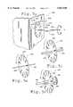
- FIGS. 3A and 3Billustrate a hollow shaft used for determining the rotation of an elongated flexible object.
- FIG. 3Aillustrates a side view of the shaft, including a depression of depth "D".
- FIG. 3Bis a cross section of FIG. 3A, taken along the line 3B--3B.
- FIGS. 4A and 4Billustrate a second configuration of a shaft used to determine the rotation of an elongated flexible object.
- FIG. 4Aillustrates a side view of the shaft, having a bend of depth "D".
- FIG. 4Bis an illustration of a cross section taken along line 4B--4B as the shaft is rotated through 360°.
- FIGS. 5A, 5B, 5C, 5D, 5E, 5F and 5Gillustrate rotation sensors in accordance with the present invention.
- FIG. 5Aillustrates one embodiment of a rotational sensor of the invention including a shaft coupled to a disk.
- FIG. 5Billustrates a second rotational sensor including a disk having an aperture dimensioned to engagedly receive a shaft.
- FIG. 5Cillustrates another rotational sensor embodiment wherein a disk includes a key dimensioned to receive a shaft having a flat.
- FIG. 5Dillustrates a rotational sensor fixedly coupled to a shaft.
- FIG. 5E, 5F and 5Geach illustrate an embodiment of the invention wherein the rotation of a shaft is determined using an optical encoder.
- FIG. 6is an illustration of two apparatuses of the invention arranged in a tandem configuration.
- FIG. 7is an illustration of an apparatus of the invention mounted on a gimbal mechanism.
- a virtual reality system 100used to simulate a medical procedure including a human/computer interface apparatus 102, a electronic interface 104 and a computer 106 is shown.
- the illustrated virtual reality system 100is directed to a virtual reality simulation of a catheter procedure.
- the software of the simulationis not a part of this invention and thus will not be discussed in any detail. However, such software is commercially available. Suitable software drivers which interface such simulation software with computer input/output (I/O) devices are also available commercially, e.g., from Immersion Human Interface Corporation of Palo Alto, Calif., USA.
- a catheter 108 used in conjunction with the present inventionis manipulated by an operator and virtual reality images are displayed on a screen 110 of the digital processing system in response to such manipulations.
- the digital processing systemis a personal computer or workstation, such as an IBM-PC AT or Macintosh personal computer, or a SUN or Silicon Graphics workstation.
- the digital processing systemis a personal computer which operates under the MS-DOS operating system in conformance with an IBM PC AT standard.
- the human/interface apparatus 102includes a barrier 112 and a "central line" 114 through which the catheter is inserted into the body.
- the barrier 112is used to represent portion of the skin covering the body of a patient.
- barrier 112is formed from a mannequin or other life-like representation of a body or body portion, e.g., the torso, arm or leg.
- Central line 114is inserted into the body of the patient to provide an entry and removal point from the body of the patient for the catheter 108, and to allow the manipulation of the distal portion of the catheter 108 within the body of the patient while minimizing tissue damage.
- Catheter 108 and central line 114are commercially available from sources such as Target Therapeutics of Fremont, California, USA and U.S. Surgical of Connecticut, USA.
- the catheter 108is modified such that the end of the tool (such as any cutting edges) are removed, leaving only the handle and the shaft.
- the end of the catheter tool 108is not required for the virtual reality simulation, and is removed to prevent any potential damage to persons or property.
- the catheter 108includes a handle or "grip" portion 116 and a shaft portion 118.
- the grip portioncan be any conventional device used to manipulate the catheter, or the grip may comprise the shaft portion itself.
- the shaft portionis an elongated flexible object and, in particular, is an elongated cylindrical object.
- the present inventionis concerned with tracking the movement of the shaft portion 118 in three-dimensional space, where the movement has been constrained such that the shaft portion 118 has only two, three or four degrees of motion. This is a good simulation of the typical use of a catheter 108 in that once the catheter is inserted into a patient, it is limited to about two degrees of freedom. More particularly, the shaft 118 is constrained at some point of along its length such that it can move with two degrees of freedom within the patient's body.
- the present inventionwill be discussed with reference to the shaft portion 118 of catheter tool 108, it will be appreciated that a great number of other types of objects can be used with the method and apparatus of the present invention.
- the present inventioncan be used with any elongated mechanical object where it is desirable to provide a human/computer interface with three or four degrees of freedom.
- Such objectsmay include catheters, hypodermic needles, wires, fiber optic bundles, screw drivers, pool cues, etc.
- the described preferred embodiment of the present inventioncontemplates the use of a elongated cylindrical mechanical object, other embodiments of the present invention provide a similar human/computer interface for an elongated mechanical objects which are not cylindrical in shape.
- the electronic interface 104is a part of the human/computer interface apparatus 102 and couples the apparatus 102 to the computer 106. More particularly, interface 104 is used in preferred embodiments to couple the various actuators and sensors contained in apparatus 102 (which actuators and sensors are described in detail below) to computer 106.
- An electronic interface 104 that is particularly well adapted for the presentis described in U.S. Pat. application Ser. No. 08/092,974, filed Jul. 16, 1993, issued Nov. 19, 1996, as U.S. Pat. No. 5,576,727 and entitled "3-D Mechanical Mouse” which application is assigned to the assignee of the present invention and incorporated herein by reference in its entirety.
- the electronic interface described thereinwas designed for the Immersion PROBETM 3-D mechanical mouse and has six channels corresponding to the six degrees of freedom of the Immersion PROBE.
- the electronic interface 104requires the use of only two, three or four of the six channels, since the present invention is preferably constrained to no more than two, three or four degrees of freedom.
- the electronic interface 104is coupled to a human/computer interface apparatus 120 of the apparatus 102 by a cable 122 and is coupled to the computer 106 by a cable 124.
- interface 104serves solely as an input device for the computer 106.
- interface 104serves solely as an output device for the computer 106.
- the interface 104serves as an input/output (I/O) device for the computer 106.
- Apparatus 120is shown in greater detail at 200 in FIG. 2.
- Apparatus 200includes an object receiving portion 202 into which an elongated flexible object 204, such as a catheter, is introduced through aperture 205.
- Elongated flexible object 204passes through the interior of object receiving portion 202, the interior of which receiving portion includes one or more electromechanical transducers coupled with the object receiving portion and associated with the elongated flexible object, such as actuator 206 and translation transducer 208.
- the elongated flexible object 204exits the object receiving portion 202 through a second aperture 209 whereupon the elongated flexible object passes through rotational transducer 210 which rotational transducer is rotatably coupled to the object receiving portion.
- the object receiving portion 202is preferably fashioned from a unitary mass of material made from aluminum or some other lightweight material, such as a plastic, that preferably is cast, molded, and/or machined as a monoblock member having the aforementioned actuator, translation transducer and rotation transducer.
- the object receiving portioncan also be a housing to which various acutators, transducers and sensors are coupled.
- the terms “associated with”, “related to”, or the likeare meant to indicate that the electromechanical transducer is influenced by or influences one of the degrees of freedom of the elongated flexible object 204.
- the electromechanical transducerscan be input transducers, in which case they sense motion along a respective degree of freedom and produce an electrical signal corresponding thereto for input into computer 106.
- the electromechanical transducerscan be output transducers which receive electrical signals from computer 106 that cause the transducers to impart a force on the object in accordance with their respective degrees of freedom.
- the electromechanical transducerscan also be hybrid or bi-directional transducers which operate both as sensors and as actuator devices.
- transducersare input transducers ("sensors”)
- sensorscan include encoded wheel transducers, potentiometers, optical encoders, etc.
- Output transducersinclude stepper motors, servo motors, magnetic particle brakes, friction brakes, pneumatic actuators, etc.
- Hybrid or bi-directional transducersoften pair input and output transducers together, but may also include a purely bi-directional transducer such as a permanent magnet electric motor/generator.
- an absolute sensoris one which the angle of the sensor is known in absolute terms, such as with an analog potentiometer.
- Relative sensorsonly provide relative angle information, and thus require some form of calibration step which provides a reference position for the relative angle information.
- the sensors described hereinare primarily relative sensors. In consequence, there is an implied calibration step after system power-up wherein the shaft is placed in a known position within the gimbal mechanism and a calibration signal is provided to the system to provide the reference position mentioned above. All angles provided by the sensors are thereafter relative to that reference position.
- Such calibration methodsare well known to those skilled in the art and, therefore, will not be discussed in any great detail herein.
- actuator 206is a solenoid comprising a base/sensor portion 212 to which is coupled a lower interface 214 by a shaft 216.
- the lower interface portion 214engages elongated flexible object 204 against upper interface portion 218 by applying a force in a direction substantially perpendicular to the direction of translation of the elongated flexible object 204, which direction is indicated by the linear bi-directional arrow, to produce thereby a frictional force along the direction of translation of the object 204.
- Such solenoidsare available commercially from, e.g., Guardian Electric (Woodstock, Ill., USA).
- actuator 206can also be a pneumatic or hydraulic device which applies a force to elongated flexible object 204.
- actuator 206can also be a pneumatic or hydraulic device which applies a force to elongated flexible object 204.
- the choice of a electromechanical, electromagnetic, pneumatic or hydraulic actuatorwill depend in part on the response time, cost and complexity of the device.
- the actuatorhas a response time suitable for realistic simulations (i.e., a fast response time), a low cost and low complexity.
- Electromechanical/electromagnetic transducersare preferred as they typically have a fast response time, low cost are smaller and simpler than hydraulic and pneumatic devices performing the same or similar function.
- FIG. 2Aillustrates a preferred solenoid embodiment at 238.
- Solenoid 238includes a base/sensor portion 240 which is coupled with a lower interface 242 through a reciprocating shaft 244.
- Lower interface 242comprises a platform 246 which is coupled with shaft 244 and upon which platform is coupled an optional resilient pad 246 and a brake pad 250.
- Resilient pad 248comprises a substance which effective to act as a shock absorber, such as rubber, and is optional.
- Brake pad 250comprises a substance which is effective to stop or slow the translational motion of elongated flexible object 204 when the lower interface 242 engages the elongated flexible object 204 against upper interface 252.
- the materials appropriate for the optional shock absorber and brake padwill be apparent to those of skill in the art.
- Upper interface 252includes a fixed support 254 which may be coupled to the object receiving portion or to the base/sensor 240. To the fixed support 254 is coupled a second resilient pad 256 and a second brake pad 258, both of which are comprised of the same materials as resilient pad 246 and brake pad 250.
- translation transducer 208includes a wheel 200 which wheel is mounted on a shaft 222 coupled to a sensor 224 which sensor is coupled to object receiving portion 202 by a base 226.
- Translation transducer 208is adapted to determine translational motion of elongated flexible object 204 by sensing positions of the elongated flexible object along the direction of translation thereof and producing electrical signals corresponding to the positions, as illustrated in FIG. 2B.
- Wheel 220engages elongated flexible object 204 with a normal force (downward arrow) such that translation of elongated flexible object 204 (indicated by the bi-directional linear arrow) causes rotation of shaft end 247 (indicated by the bi-directional curved arrow) creating an electrical signal from sensor 224 (not shown) which is recorded by interface 104 (also not shown).
- translation transducer 208could also be an output transducer (actuator) and apply a frictional braking force to elongated object 204 to simulate such effects as drag experienced by the catheter as the catheter traverses various vessels in the body.
- Such transducersare well known in the art and available commercially.
- One preferred transduceris an optical encoder model SI marketed by U.S.
- This transduceris an encoded wheel type input transducer.
- a preferred output transducer for use of the present inventionis a d.c. motor model 2434.970-50 produced by Maxon of Fall River, Mass. USA.
- This type of transduceris a servo motor type output transducer.
- Rotational transducer 210is rotatably coupled to object receiving portion 202 to determine the rotational motion of elongated flexible object 204.
- Rotational transducer 210includes a disk 228 coupled with a hollow shaft 232.
- the disk and hollow shaftare attached, e.g., by gluing or press fitting, to provide a substantially unitary device.
- the disk 228includes an aperture (not shown) dimensioned to receive the elongated flexible object and the hollow shaft is dimensioned to receivably engage the elongated flexible object such that disk 228 substantially tracks the rotational motion of the elongated flexible object 204; yet provides minimal translational friction.
- the rotation of the diskis detected by sensor 230, as will be described in greater detail below.
- Hollow shaft 232is illustrated in greater detail in FIG. 3A which provides a cut-away view of the elongated object and the hollow shaft at 300.
- Hollow shaft 302is preferably made from stainless steel.
- the hollow shaftis dimensioned to engagably receive elongated object 304 with a gap 306 between hollow shaft 302 and elongated flexible object 304 sufficient to allow translation of the elongated flexible object without substantial interference from the interior surface of the hollow shaft; yet small enough that the hollow shaft rotates substantially continuously with the elongated flexible object.
- Gap 306is further illustrated in FIG. 3B, a cut-away view taken along the line 3B--3B of FIG. 3A, where the size of the gap is denoted "d".
- dis chosen such that the hollow and shaft and the elongated flexible object have a tight engaging fit.
- the diameter of the hollow shaftis between about 120% and about 150% of the diameter of the elongated flexible object, i.e., the size of the gap is between about 20% and about 50% of the diameter of the elongated flexible object.
- preferred values for dare between about 0.001 inches and about 0.010 inches and, more preferably, between about 0.003 inches and about 0.006 inches.
- the hollow shaftcan further include substances to increase or decrease the friction between the interior wall of the hollow shaft and the surface of the elongated flexible object. Such substances are known to persons of skill in the art.
- hollow shaft 302further includes at least one bend, such as that shown generally at 308, where two bends in substantially opposite directions are illustrated.
- one or two bends included in the hollow shaftPreferably the sections of the hollow shaft on each side of the bend(s) are substantially parallel. The bend(s) function to allow the hollow shaft and disk 228 to track the rotational motion of the elongated flexible object while offering little impedance to the translational movement of the elongated flexible object.
- DThe depth of the bend is denoted by "D".
- Dis chosen such that the hollow shaft and elongated flexible object have the desired rotation tracking and translation characteristics. It has been found that preferred values for D depend on several factors, including the stiffness of the elongated object and the tightness of fit between the hollow shaft and the elongated flexible object. Stiffer elongated objects typically require a smaller value of D to achieve desirable rotation and translation properties for a given gap d than more flexible objects having the same value of d. For example, for values of d between about 0.002 and 0.010 inches, D is preferably between about 0.05 and about 0.20 inches, respectively.
- FIG. 4Aillustrates a second preferred embodiment of the hollow shaft at 400, wherein a single bend 402 is placed in hollow shaft 404, which hollow shaft includes elongated flexible object 406 and gap 408, to divide the hollow shaft into two substantially parallel sections.
- FIG. 4Billustrates a cut-away view taken along line 4B--4B of FIG. 4A as the hollow shaft and elongated flexible object are rotated through 360°.
- FIG. 5A at 500illustrates a preferred embodiment of rotation transducer 210 of FIG. 2.
- rotation transducer 500includes a disk 502 rotatably coupled with object receiving portion 504 for rotation by hollow shaft 506 and elongated flexible object 508.
- the diskis preferably made from a clear, plastic material and is provided with a number of dark radial bands 510 near its circumference, such as by printing or silk screening.
- a photodetector pair 512 including a light source 512a and a detector 512bare positioned on opposing sides of disk 502 in alignment with the bands 510.
- the bands 510alternatively allow light emanating from light source 512a to impinge or not impinge upon the detector 512b.
- the electronic interface 104coupled to the photodetector 512 by cable 514, counts the bands 510 as they pass the photodetector 512b to provide a signal on cable 122 to the computer 106 indicating the rotational position of the hollow shaft 506 and elongated flexible object 508 around axis A.
- the photodetectormay also be provided as two pairs of photodetectors to determine the direction of rotation, as is well known to those skilled in the art of sensor design and described in U.S. Pat. application Ser. No. 08/275,120, issued Apr. 22, 1997, as U.S. Pat. No. 5,623,582.
- FIG. 5Billustrates an alternate embodiment of the rotation transducer at 518, wherein disk 520 tracks the rotation of shaft 522 extending engagably through an aperture 524 in disk 520.
- the engagement between shaft 522 and disk aperture 524preferably is accomplished by the formation of a frictional seal between the disk aperture and shaft, as described in greater detail in U.S. Pat. application Ser. No. 08/275,120, issued Apr. 22, 1997, as U.S. Pat. No. 5,623,582.
- FIG. 5Cillustrates a second alternate embodiment at 530, wherein disk 532 is engaged with shaft 534 including a flat portion 535, which shaft extends through a key way 536 dimensioned to receivably engage shaft 534 and flat portion 535.
- Both disks 520 and 532include dark radial bands near their circumferences to be used in conjunction with a photodetector as described above.
- the rotation transducercomprises a disk 542 including a sleeve 544 dimensioned to receive and fixedly hold an end portion 548 of shaft 546.
- the sleeveis rotatably coupled to a bearing 550 which bearing is coupled to a wall of the object receiving portion.
- Disk 542is preferably provided with a number of dark radial bands near its circumference, such as by printing or silk screening, for use with an optical rotation detector as just described. It will be appreciated, however, that this embodiment does not allow translation of shaft 546 through disk 542.
- FIG. 5E at 560illustrates an embodiment wherein object receiving portion 562, including an actuator and translation transducer shown generally at 563 and as described above with respect to FIG. 2, contact shaft 564 which shaft is fixedly engaged with a fixed rotary sensor 566, the sensor comprising an optical encoder 568 which is coupled by a connection 570 to interface 104. Rotational motion at the end of the shaft 564 (see arrow) is sensed by the optical encoder which transmits signals to the interface for analysis by computer 106. Translational motion is also accommodated as illustrated in FIG. 5F.
- FIG. 5Gillustrates an alternate embodiment at 580 wherein the object receiving portion 582 which fixedly receives shaft 564 is positioned laterally from optical encoder 586 to thereby create a bend in shaft 584 as indicated at 588. Rotational motion at the distal end of the shaft is sensed at the optical encoder while translational motion is sensed as described above.
- FIG. 6A preferred tandem configuration for simulating a procedure such as an epidural procedure is shown in FIG. 6 at 600.
- First and second object receiving portions 602 and 604respectively are placed in an adjoining configuration, indicated by the dashed lines, and are substantially identical to object receiving portion 202 described above with respect to FIG. 2.
- Both object receiving portions 602 and 604are adapted to receive "epidural" device 606, which device includes external shaft 608 and elongated flexible object 610 which object can be coupled to an external control such as handle 612.
- actuator 614Within object receiving portion 602 is preferably included actuator 614, which actuator includes a base/sensor 616, a lower interface portion 618 and a shaft 620, in addition to upper interface portion 622 which is coupled to support 624.
- Object receiving portion 602also preferably includes translation transducer 626, which transducer includes wheel 628 and sensor 630.
- object receiving portion 604includes preferably actuator 632, which actuator includes a base/sensor 634, a lower interface portion 636 and a shaft 638, in addition to upper interface portion 640 which is coupled to support 642.
- Object receiving portion 604also preferably includes translation transducer 644, which transducer includes wheel 646 and sensor 648.
- the actuators and transducers, and their respective components,are all substantially identical to those described above with respect to FIG. 2.
- Object receiving portion 604is further rotatably coupled to rotation transducer 650, which transducer includes disk 652 and sensor 654.
- Disk 652is coupled to hollow shaft 656 which is dimensioned to engagably receive elongated flexible object 610.
- Rotation transducer 650, including disk 652, sensor 654 and hollow shaft 656are of substantially identical to those analogous components discussed above with respect to FIG. 5A. It will be appreciated that the alternative rotation sensor embodiments discussed above with respect to FIGS. 5B-5G can be used as well.
- a second preferred configurationis one wherein either actuator 614 or transducer 626 is omitted. It will also be appreciated that the actuators and transducers may be combined in a single object receiving portion.
- the object receiving portionis part of a gimbal apparatus as shown at 700 in FIG. 7.
- the gimbal apparatus 700preferably includes object receiving portion 702, a U-shaped base portion 704 and a support 706.
- the U-shaped base portionis rotatably coupled to the support and includes a base 708 and a pair of substantially parallel legs 710a and 710b extending upwardly therefrom that are capable of rotation about axis A 1 .
- substantially parallelwill mean that two objects or axis are exactly or almost parallel, i.e., the legs are at least within five or ten degrees of parallel, and are preferably within less than one degree of parallel.
- substantially perpendicularwill mean that two objects or axes are exactly or almost perpendicular, i.e., the legs are at least within five degrees or ten degrees of perpendicular, and, more preferably, within less than one degree of perpendicular.
- the elongated flexible object receiving portion 702is provided with object inlet portion 712 which object inlet portion includes an aperture 714 extending entirely through the object receiving portion.
- the aperture 714defines an object axis A 0 for an elongated flexible object, such as the shaft portion 118 of the catheter 108 of FIG. 1.
- the object inlet portion 712is at least partially disposed between the legs 710a and 710b of the U-shaped base portion, and is pivotally coupled thereto such as by a pair of pivots, one of which is shown as pivot 716a in leg 710a, which pivot lies on axis A 2
- Another pivot 716b(not shown) is provided in leg 710b.
- Axes A 1 and A 2are substantially mutually perpendicular and intersect at an origin point O within object inlet portion 712.
- Axis A 0also intersects this origin O and is substantially perpendicular to axes A 1 and A 2 .
- the object receiving portion 702also includes a actuator interface 718 and a translation interface 719. In some preferred embodiments, a second actuator interface 720 and a second translation interface 721 may be included as shown.
- the object receiving portion 702includes a bearing section 722, an actuator section 724, a translation sensor section 725, and optionally a second actuator section 726 and translation section 727 as shown.
- the object receiving portionalso includes rotation sensor section 728.
- the bearing section 722includes a mass of material provided with a cylindrical bore 730 forming a portion of the aperture 714.
- the actuator sensor section 724includes a pair of opposing wall surfaces 732a and 732b, each of which is provided with a cylindrical bore receptive to the cylindrical object and forming a part of the aperture 714 which extends through the object receiving portion.
- the translation sensor section 725includes a pair of opposing wall surfaces 734a and 734b of a wall and which are provided with cylindrical bores receptive to the elongated flexible object and therefore also forming a part of the aperture 714.
- Optional second actuator sensor section 726 and translation section 727include opposite facing walls 738a and 738b and 740a and 740b, respectively, which walls are analogous to the walls of actuator sensor section 724 and translation sensor section 725 just described.
- the object receiving portion 702is preferably a unitary mass of material made from aluminum or some other lightweight material such as a plastic, preferably cast, molded, and/or machined as a monoblock member having the aforementioned bearing section, translation sensory section, and rotation sensory sections.
- the materials and construction of U-shaped base portion 704preferably match the materials and construction techniques used for the production of object receiving portion 702.
- the gimbal apparatus 700 illustrated in FIG. 7constrains an object that is engaged with the object receiving portion 702 to four degrees of freedom. This is accomplished by allowing the U-shaped base portion 704 to rotate around an axis A 1 relative to the support 706, by allowing the object receiving portion 702 to rotate around an axis A 2 relative to the U-shaped base portion 704, by allowing the object to translate as illustrated by the bi-directional arrow "t" along axis A 0 of aperture 714, and by allowing the object to rotate as indicated by arrow "r” around the axis A 0 of aperture 714.
- a first degree of freedom electromechanical transducer 744is arranged to transduce motion and/or force between the U-shaped base portion 708 and the support 706, a second degree of freedom electromechanical transducer 746 is arranged to transduce motion and/or force between leg 710a of U-shaped base portion 708 and the object inlet portion 712, a third degree of freedom electromechanical actuator 748, including lower interface 750 and upper interface 752, is arranged to transduce force between the object receiving portion 702 and an object engaged with the object receiving portion 702, a third degree of freedom electromechanical transducer wheel 754 and sensor 756 is also arranged to transduce motion between the object receiving portion 702 and an object engaged with the object receiving portion 702.
- a second third degree of freedom actuator 758including upper and lower interfaces 760 and 762 respectively, and a second third degree of freedom transducer wheel 764 and sensor 766 can be arranged as just described for actuator 748 and translation transducer 756.
- a fourth degree of freedom transducer 768including disk 770, hollow shaft 772 and sensor 774 as described above, is engaged between the object receiving portion 702 and an object engaged with the object receiving portion 702.
- a housing of transducer 744is attached to the U-shaped base portion 704, and a shaft of the transducer extends through an oversize bore (not shown) in base 708 to engage a press-fit bore (also not shown) in support 706. Therefore, rotation of the U-shaped base portion 704 around axis A 1 will cause a rotation of a shaft of transducer 744.
- a housing of transducer 746is attached to leg 710a of the U-shaped base portion 704 such that its shaft forms pivot 716a.
- Actuator sensor 748is attached to a wall of actuator section 724, and a shaft of the actuator extends through a bore in the wall to connect lower interface 750 to the actuator sensor.
- Upper interface 752is fixedly attached to a wall of actuator section 748.
- the transducer 756is attached to object receiving portion 702 and extends through a bore (not shown) in a wall 776 of the translation sensor section 725.
- the shaft of wheel 754provides the axis for the translation interface 719 and rotates with the rotation of the translation interface 719.
- Optional actuator section 726 and translation section 727are constructed analogously.
- Disk 770is rotatable coupled to a wall 778 of rotation sensor section 768 and extends through a bore 780 in wall 778.
- a photodetector 774is attached to wall 778 and engages a circumferential surface of disk 770 to sense the rotation thereof.
- the shaft 118 of a catheter 108is inserted into aperture 714 along axis A 0 , causing the shaft 118 to frictionally engage the actuator interface 718 and the translation interface (wheel) 719.
- the translational interface 719is a friction wheel made out of a rubber-like material.
- the shaft 118is also in engagement with the rotation interface 768 and extends through hollow shaft 772. Rotation of the shaft 118 around the axis A 0 as illustrated by the arrow "r" will cause a rotation of disk 770 which is registered on sensor 774.
- a translation of the shaft 118 along axis A 0will not be affected appreciably by hollow shaft 772 or disk 770, but will cause a rotation of the friction wheel 754 which rotates the shaft of the transducer 756.
- a movement up or down of the catheter 108will cause a rotation of the shaft (pivot) 716a of transducer 746, and a side-to-side pivoting of the catheter 108 will cause a rotational about axis A 1 which is detected by transducer 744.
- catheter 108is an "epidural" instrument
- the translational and rotational movements of the catheterwill be tracked as just described, except that the translation section 727 and actuator section 726 will be used.
- the translational motion of the "needle”will be handled by translation section 725 and actuator 724 as described above for the case wherein a catheter is inserted through aperture 714.
- the transducersare input transducers, ie., the human/computer interface device is used an input device to the computer 106.
- the interface device 102can serve as an output device for the computer 106.
- output transducersWhen used as an output device, output transducers (“actuators") are used to respond to electrical signals developed by the computer 106 to impart a force upon the shaft 118 of catheter 108. This can provide useful movement and force (haptic) feedback to the doctor/trainee or other user.
- a forcecan be generated by actuator 748 making it harder for the doctor/trainee to push the shaft 118 further into the gimbal apparatus 700.
- twisting motionscan be imparted on the shaft 118 when the shaft encounters an obstacle within the virtual patient.
- force applied to the shaftmay not result in any movement of the shaft. This is because the shaft may be inhibited from movement by the hand of the operator who is grasping a handle or grip portion of the shaft. However, the force applied to the shaft may be sensed by the operator as haptic feedback.
- a method for mechanically interfacing an elongated mechanical object with an electrical system in accordance with the present inventionincludes first step of defining an origin in 3-dimensional space. This corresponds to the origin O at the intersection of axes A 1 and A 2 .
- a second stepis to physically constrain an elongated object in the 3-dimensional space such that a portion of the object always intersects the origin O and such that a portion of the object extending from the origin O defines a radius in a spherical coordinate system.
- the elongated object(such as shaft 118 of catheter 108) is physically constrained in a 3-dimensional space by the aperture 714 of the object receiving portion 702.
- the portion of the shaft 118 extending from origin Odefines the radius.
- a third stepincludes transducing a first electrical signal related to a first angular coordinate of the radius with a first transducer. This corresponds to the operation of transducer 744 which transduces a first electrical signal related to a first angular coordinate of the radius.
- a fourth stepis transducing a second electrical signal related to a second angular coordinate of the radius. This corresponds to the operation of transducer 746 which transduces a second electrical signal.
- a fifth stepis to transduce a third electrical signal related to the length of the radius, which corresponds to the operation of transducers 756 and/or 762.
- a sixth and final stepis to electrically couple the transducers to an electrical system which, in this instance, is preferably a computer 106.
- An additional steptransduces a fourth electrical signal related to a rotation of the object around an object axis which intersects the origin O. This step corresponds to the operation of rotation transducer 768.
- the transducerscan be input transducers, output transducers, or bi-directional transducers.
- the electrical system most frequently described in the present inventionis a digital processing system or a computer.
- other digital systems, analog systems, and simple electric or electromechanical systemcan also be utilized with the apparatus and method of the present invention.
- the "grip”can be a functional grip or handle attached to an elongated portion of the object, or the grip can be a portion of the object itself (i.e., the shaft, wire or catheter), such as a portion of the length of a shaft that can be gripped and/or manipulated by the operator.
- flexible shaftssuch as wires or catheters
- a human/computer interface for a catheter insertion virtual reality systemonly a translation interface and a rotation interface such as illustrated in FIG. 2 may be required.
- a cathetercan be moved in and out of a virtual patient (as sensed by translation interface 725) and can be twisted or rotated (as sensed by rotation interface 768), but cannot be, in any practical manner, moved up or down or from side-to-side due to the environmental constraints operating on the catheter.
- two extra degrees of freedomsuch as those provided by gimbal apparatus 700, to fix an angle in three dimensions; thereby, creating a more difficult, and realistic, scenario for the operator/trainee.
Landscapes
- Engineering & Computer Science (AREA)
- Health & Medical Sciences (AREA)
- General Physics & Mathematics (AREA)
- Physics & Mathematics (AREA)
- Medical Informatics (AREA)
- Surgery (AREA)
- Life Sciences & Earth Sciences (AREA)
- General Health & Medical Sciences (AREA)
- Chemical & Material Sciences (AREA)
- Nuclear Medicine, Radiotherapy & Molecular Imaging (AREA)
- Animal Behavior & Ethology (AREA)
- Heart & Thoracic Surgery (AREA)
- Public Health (AREA)
- Veterinary Medicine (AREA)
- Pulmonology (AREA)
- Radiology & Medical Imaging (AREA)
- Biomedical Technology (AREA)
- Medicinal Chemistry (AREA)
- Robotics (AREA)
- Algebra (AREA)
- Computational Mathematics (AREA)
- Molecular Biology (AREA)
- Mathematical Analysis (AREA)
- Mathematical Optimization (AREA)
- Mathematical Physics (AREA)
- Pure & Applied Mathematics (AREA)
- Business, Economics & Management (AREA)
- Educational Administration (AREA)
- Educational Technology (AREA)
- Theoretical Computer Science (AREA)
- Human Computer Interaction (AREA)
- Manufacturing & Machinery (AREA)
- Automation & Control Theory (AREA)
- Position Input By Displaying (AREA)
Abstract
Description
Claims (66)
Priority Applications (2)
| Application Number | Priority Date | Filing Date | Title |
|---|---|---|---|
| US08/825,412US5821920A (en) | 1994-07-14 | 1997-03-28 | Control input device for interfacing an elongated flexible object with a computer system |
| US09/153,938US6215470B1 (en) | 1994-07-14 | 1998-09-16 | User interface device including braking mechanism for interfacing with computer simulations |
Applications Claiming Priority (3)
| Application Number | Priority Date | Filing Date | Title |
|---|---|---|---|
| US08/275,120US5623582A (en) | 1994-07-14 | 1994-07-14 | Computer interface or control input device for laparoscopic surgical instrument and other elongated mechanical objects |
| US34414894A | 1994-11-23 | 1994-11-23 | |
| US08/825,412US5821920A (en) | 1994-07-14 | 1997-03-28 | Control input device for interfacing an elongated flexible object with a computer system |
Related Parent Applications (1)
| Application Number | Title | Priority Date | Filing Date |
|---|---|---|---|
| US34414894AContinuation | 1994-07-14 | 1994-11-23 |
Related Child Applications (1)
| Application Number | Title | Priority Date | Filing Date |
|---|---|---|---|
| US09/153,938ContinuationUS6215470B1 (en) | 1994-07-14 | 1998-09-16 | User interface device including braking mechanism for interfacing with computer simulations |
Publications (1)
| Publication Number | Publication Date |
|---|---|
| US5821920Atrue US5821920A (en) | 1998-10-13 |
Family
ID=26957263
Family Applications (2)
| Application Number | Title | Priority Date | Filing Date |
|---|---|---|---|
| US08/825,412Expired - LifetimeUS5821920A (en) | 1994-07-14 | 1997-03-28 | Control input device for interfacing an elongated flexible object with a computer system |
| US09/153,938Expired - LifetimeUS6215470B1 (en) | 1994-07-14 | 1998-09-16 | User interface device including braking mechanism for interfacing with computer simulations |
Family Applications After (1)
| Application Number | Title | Priority Date | Filing Date |
|---|---|---|---|
| US09/153,938Expired - LifetimeUS6215470B1 (en) | 1994-07-14 | 1998-09-16 | User interface device including braking mechanism for interfacing with computer simulations |
Country Status (1)
| Country | Link |
|---|---|
| US (2) | US5821920A (en) |
Cited By (182)
| Publication number | Priority date | Publication date | Assignee | Title |
|---|---|---|---|---|
| WO1999039317A1 (en)* | 1998-01-28 | 1999-08-05 | Ht Medical Systems, Inc. | Interface device and method for interfacing instruments to medical procedure simulation system |
| WO1999039315A3 (en)* | 1998-01-28 | 1999-11-25 | Ht Medical Systems Inc | Interface device and method for interfacing instruments to vascular access simulation systems |
| US6020875A (en)* | 1997-10-31 | 2000-02-01 | Immersion Corporation | High fidelity mechanical transmission system and interface device |
| US6024576A (en)* | 1996-09-06 | 2000-02-15 | Immersion Corporation | Hemispherical, high bandwidth mechanical interface for computer systems |
| US6067077A (en) | 1998-04-10 | 2000-05-23 | Immersion Corporation | Position sensing for force feedback devices |
| US6084587A (en)* | 1996-08-02 | 2000-07-04 | Sensable Technologies, Inc. | Method and apparatus for generating and interfacing with a haptic virtual reality environment |
| US6104382A (en) | 1997-10-31 | 2000-08-15 | Immersion Corporation | Force feedback transmission mechanisms |
| US6106301A (en) | 1996-09-04 | 2000-08-22 | Ht Medical Systems, Inc. | Interventional radiology interface apparatus and method |
| US6154198A (en) | 1995-01-18 | 2000-11-28 | Immersion Corporation | Force feedback interface apparatus including backlash and for generating feel sensations |
| US6191796B1 (en) | 1998-01-21 | 2001-02-20 | Sensable Technologies, Inc. | Method and apparatus for generating and interfacing with rigid and deformable surfaces in a haptic virtual reality environment |
| US6201533B1 (en) | 1995-01-18 | 2001-03-13 | Immersion Corporation | Method and apparatus for applying force in force feedback devices using friction |
| US6215470B1 (en)* | 1994-07-14 | 2001-04-10 | Immersion Corp | User interface device including braking mechanism for interfacing with computer simulations |
| US6259433B1 (en)* | 1996-05-14 | 2001-07-10 | Norman H. Meyers | Digital optical joystick with mechanically magnified resolution |
| US6271828B1 (en) | 1995-01-18 | 2001-08-07 | Immersion Corporation | Force feedback interface devices providing resistance forces using a fluid |
| US6281651B1 (en) | 1997-11-03 | 2001-08-28 | Immersion Corporation | Haptic pointing devices |
| US20010032278A1 (en)* | 1997-10-07 | 2001-10-18 | Brown Stephen J. | Remote generation and distribution of command programs for programmable devices |
| US6323837B1 (en) | 1994-07-14 | 2001-11-27 | Immersion Corporation | Method and apparatus for interfacing an elongated object with a computer system |
| US6375471B1 (en)* | 1998-07-10 | 2002-04-23 | Mitsubishi Electric Research Laboratories, Inc. | Actuator for independent axial and rotational actuation of a catheter or similar elongated object |
| US6400352B1 (en) | 1995-01-18 | 2002-06-04 | Immersion Corporation | Mechanical and force transmission for force feedback devices |
| US6404417B1 (en)* | 1999-03-22 | 2002-06-11 | Logitech Europe S.A. | Direct drive rotational sensor adapted to withstand off-axis loading |
| US6405158B1 (en) | 1993-10-01 | 2002-06-11 | Massachusetts Institute Of Technology | Force reflecting haptic inteface |
| US20020087169A1 (en)* | 1998-02-24 | 2002-07-04 | Brock David L. | Flexible instrument |
| US6421048B1 (en) | 1998-07-17 | 2002-07-16 | Sensable Technologies, Inc. | Systems and methods for interacting with virtual objects in a haptic virtual reality environment |
| US6437771B1 (en) | 1995-01-18 | 2002-08-20 | Immersion Corporation | Force feedback device including flexure member between actuator and user object |
| US20020128633A1 (en)* | 1998-02-24 | 2002-09-12 | Brock David L. | Surgical instrument |
| US6538634B1 (en) | 1998-12-18 | 2003-03-25 | Kent Ridge Digital Labs | Apparatus for the simulation of image-guided surgery |
| US6552722B1 (en) | 1998-07-17 | 2003-04-22 | Sensable Technologies, Inc. | Systems and methods for sculpting virtual objects in a haptic virtual reality environment |
| US6564168B1 (en) | 1999-09-14 | 2003-05-13 | Immersion Corporation | High-resolution optical encoder with phased-array photodetectors |
| WO2003050783A1 (en)* | 2001-12-11 | 2003-06-19 | Keymed (Medical And Industrial Equipment) Ltd | An apparatus for use in training an operator in the use of an endoscope system |
| US6639581B1 (en) | 1995-11-17 | 2003-10-28 | Immersion Corporation | Flexure mechanism for interface device |
| US6657617B2 (en) | 2001-06-25 | 2003-12-02 | International Business Machines Corporation | Method, apparatus and computer program product for three dimensional text creation |
| US6671651B2 (en) | 2002-04-26 | 2003-12-30 | Sensable Technologies, Inc. | 3-D selection and manipulation with a multiple dimension haptic interface |
| US20040019447A1 (en)* | 2002-07-16 | 2004-01-29 | Yehoshua Shachar | Apparatus and method for catheter guidance control and imaging |
| US6693622B1 (en) | 1999-07-01 | 2004-02-17 | Immersion Corporation | Vibrotactile haptic feedback devices |
| US20040142314A1 (en)* | 2003-01-22 | 2004-07-22 | Harrith M. Hasson | Medical training apparatus |
| US20040233161A1 (en)* | 1999-07-01 | 2004-11-25 | Shahoian Erik J. | Vibrotactile haptic feedback devices |
| US6850222B1 (en) | 1995-01-18 | 2005-02-01 | Immersion Corporation | Passive force feedback for computer interface devices |
| US6859671B1 (en) | 1995-05-30 | 2005-02-22 | Roy-G-Biv Corporation | Application programs for motion control devices including access limitations |
| US6857878B1 (en) | 1998-01-26 | 2005-02-22 | Simbionix Ltd. | Endoscopic tutorial system |
| US6867770B2 (en) | 2000-12-14 | 2005-03-15 | Sensable Technologies, Inc. | Systems and methods for voxel warping |
| US6885898B1 (en) | 2001-05-18 | 2005-04-26 | Roy-G-Biv Corporation | Event driven motion systems |
| US20050088408A1 (en)* | 1999-05-11 | 2005-04-28 | Braun Adam C. | Method and apparatus for compensating for position slip in interface devices |
| US20050096589A1 (en)* | 2003-10-20 | 2005-05-05 | Yehoshua Shachar | System and method for radar-assisted catheter guidance and control |
| US20050162389A1 (en)* | 2002-04-12 | 2005-07-28 | Obermeyer Henry K. | Multi-axis joystick and transducer means therefore |
| US6929481B1 (en) | 1996-09-04 | 2005-08-16 | Immersion Medical, Inc. | Interface device and method for interfacing instruments to medical procedure simulation systems |
| US20050190150A1 (en)* | 1999-04-20 | 2005-09-01 | Microsoft Corporation | Computer input device providing absolute and relative positional information |
| US6941543B1 (en) | 1995-05-30 | 2005-09-06 | Roy-G-Biv Corporation | Motion control system and method |
| US20050214723A1 (en)* | 2004-03-23 | 2005-09-29 | David Feygin | Vascular-access simulation system with external end-effector |
| US20050214726A1 (en)* | 2004-03-23 | 2005-09-29 | David Feygin | Vascular-access simulation system with receiver for an end effector |
| US20050214724A1 (en)* | 2004-03-23 | 2005-09-29 | David Feygin | Vascular-access simulation system with ergonomic features |
| US20050214725A1 (en)* | 2004-03-23 | 2005-09-29 | David Feygin | Vascular-access simulation system with skin-interaction features |
| US20050223327A1 (en)* | 2004-03-18 | 2005-10-06 | Cunningham Richard L | Medical device and procedure simulation |
| US6958752B2 (en) | 2001-01-08 | 2005-10-25 | Sensable Technologies, Inc. | Systems and methods for three-dimensional modeling |
| US6985133B1 (en) | 1998-07-17 | 2006-01-10 | Sensable Technologies, Inc. | Force reflecting haptic interface |
| US20060008786A1 (en)* | 2004-07-08 | 2006-01-12 | David Feygin | Vascular-access simulation system with three-dimensional modeling |
| US7024666B1 (en) | 2002-01-28 | 2006-04-04 | Roy-G-Biv Corporation | Motion control systems and methods |
| US20060073454A1 (en)* | 2001-01-24 | 2006-04-06 | Anders Hyltander | Method and system for simulation of surgical procedures |
| US7031798B2 (en) | 2001-02-09 | 2006-04-18 | Roy-G-Biv Corporation | Event management systems and methods for the distribution of motion control commands |
| US7095418B2 (en) | 2003-10-30 | 2006-08-22 | Sensable Technologies, Inc. | Apparatus and methods for texture mapping |
| US7113166B1 (en) | 1995-06-09 | 2006-09-26 | Immersion Corporation | Force feedback devices using fluid braking |
| US20060234195A1 (en)* | 2002-12-03 | 2006-10-19 | Jan Grund-Pedersen | Interventional simulator control system |
| US20060241864A1 (en)* | 2005-04-22 | 2006-10-26 | Outland Research, Llc | Method and apparatus for point-and-send data transfer within an ubiquitous computing environment |
| US7137107B1 (en) | 2003-04-29 | 2006-11-14 | Roy-G-Biv Corporation | Motion control systems and methods |
| US7139843B1 (en) | 1995-05-30 | 2006-11-21 | Roy-G-Biv Corporation | System and methods for generating and communicating motion data through a distributed network |
| US7149596B2 (en) | 2004-01-13 | 2006-12-12 | Sensable Technologies, Inc. | Apparatus and methods for modifying a model of an object to enforce compliance with a manufacturing constraint |
| US20060285644A1 (en)* | 2005-06-17 | 2006-12-21 | Siemens Aktiengesellschaft | Device for medical provision |
| EP1746559A1 (en) | 2005-07-20 | 2007-01-24 | Richstone Consulting LLC | A method for simulating a manual interventional operation by a user in a medical procedure |
| EP1746558A2 (en) | 2005-07-20 | 2007-01-24 | Richstone Consulting LLC | A system and a method for simulating a manual interventional operation by a user in a medical procedure |
| US20070063971A1 (en)* | 2004-03-12 | 2007-03-22 | Xitact S.A. | Actuator for an elongated object for a force feedback generating device |
| US7209028B2 (en) | 2001-06-27 | 2007-04-24 | Immersion Corporation | Position sensor with resistive element |
| US20070103437A1 (en)* | 2005-10-26 | 2007-05-10 | Outland Research, Llc | Haptic metering for minimally invasive medical procedures |
| US7225404B1 (en) | 1996-04-04 | 2007-05-29 | Massachusetts Institute Of Technology | Method and apparatus for determining forces to be applied to a user through a haptic interface |
| US7241263B2 (en) | 2004-09-30 | 2007-07-10 | Scimed Life Systems, Inc. | Selectively rotatable shaft coupler |
| US20070166682A1 (en)* | 2003-01-22 | 2007-07-19 | Realsim Systems, Llc. | Medical training apparatus |
| US20070197891A1 (en)* | 2006-02-23 | 2007-08-23 | Yehoshua Shachar | Apparatus for magnetically deployable catheter with MOSFET sensor and method for mapping and ablation |
| US20070250072A1 (en)* | 2002-08-14 | 2007-10-25 | Hansen Medical, Inc. | Robotic medical instrument system |
| US7297142B2 (en) | 1998-02-24 | 2007-11-20 | Hansen Medical, Inc. | Interchangeable surgical instrument |
| US20070276216A1 (en)* | 2004-08-16 | 2007-11-29 | Refael Beyar | Image-Guided Navigation for Catheter-Based Interventions |
| US7307619B2 (en) | 2001-05-04 | 2007-12-11 | Immersion Medical, Inc. | Haptic interface for palpation simulation |
| US7331967B2 (en) | 2002-09-09 | 2008-02-19 | Hansen Medical, Inc. | Surgical instrument coupling mechanism |
| US20080084387A1 (en)* | 2006-10-04 | 2008-04-10 | Mcardle James | Pointing device having rotational sensors |
| US20080088578A1 (en)* | 2006-10-16 | 2008-04-17 | Immersion Corporation | Flexible object simulator |
| US7382378B2 (en) | 2003-10-30 | 2008-06-03 | Sensable Technologies, Inc. | Apparatus and methods for stenciling an image |
| US7404716B2 (en) | 2001-07-16 | 2008-07-29 | Immersion Corporation | Interface apparatus with cable-driven force feedback and four grounded actuators |
| US7411576B2 (en) | 2003-10-30 | 2008-08-12 | Sensable Technologies, Inc. | Force reflecting haptic interface |
| US7413543B2 (en) | 2003-04-01 | 2008-08-19 | Scimed Life Systems, Inc. | Endoscope with actively cooled illumination sources |
| US20080249395A1 (en)* | 2007-04-06 | 2008-10-09 | Yehoshua Shachar | Method and apparatus for controlling catheter positioning and orientation |
| US7479106B2 (en) | 2004-09-30 | 2009-01-20 | Boston Scientific Scimed, Inc. | Automated control of irrigation and aspiration in a single-use endoscope |
| US7489979B2 (en) | 2005-01-27 | 2009-02-10 | Outland Research, Llc | System, method and computer program product for rejecting or deferring the playing of a media file retrieved by an automated process |
| US7519537B2 (en) | 2005-07-19 | 2009-04-14 | Outland Research, Llc | Method and apparatus for a verbo-manual gesture interface |
| US20090131955A1 (en)* | 2005-09-29 | 2009-05-21 | Corindus Ltd. | Methods and apparatuses for treatment of hollow organs |
| US7542816B2 (en) | 2005-01-27 | 2009-06-02 | Outland Research, Llc | System, method and computer program product for automatically selecting, suggesting and playing music media files |
| US7562117B2 (en) | 2005-09-09 | 2009-07-14 | Outland Research, Llc | System, method and computer program product for collaborative broadcast media |
| US7577522B2 (en) | 2005-12-05 | 2009-08-18 | Outland Research, Llc | Spatially associated personal reminder system and method |
| US7578786B2 (en) | 2003-04-01 | 2009-08-25 | Boston Scientific Scimed, Inc. | Video endoscope |
| US20090221958A1 (en)* | 2005-05-10 | 2009-09-03 | Rafael Beyar | User interface for remote control catheterization |
| US7586032B2 (en) | 2005-10-07 | 2009-09-08 | Outland Research, Llc | Shake responsive portable media player |
| US7591783B2 (en) | 2003-04-01 | 2009-09-22 | Boston Scientific Scimed, Inc. | Articulation joint for video endoscope |
| US7597662B2 (en) | 2004-09-30 | 2009-10-06 | Boston Scientific Scimed, Inc. | Multi-fluid delivery system |
| US7604642B2 (en) | 1998-02-24 | 2009-10-20 | Hansen Medical, Inc. | Interchangeable instrument |
| US7608083B2 (en) | 2001-02-15 | 2009-10-27 | Hansen Medical, Inc. | Robotically controlled medical instrument with a flexible section |
| US20090275828A1 (en)* | 2008-05-01 | 2009-11-05 | Magnetecs, Inc. | Method and apparatus for creating a high resolution map of the electrical and mechanical properties of the heart |
| US7626589B2 (en) | 2003-12-10 | 2009-12-01 | Sensable Technologies, Inc. | Haptic graphical user interface for adjusting mapped texture |
| US20100069833A1 (en)* | 2008-05-06 | 2010-03-18 | Corindus Ltd. | Catheter system |
| US7699835B2 (en) | 2001-02-15 | 2010-04-20 | Hansen Medical, Inc. | Robotically controlled surgical instruments |
| US7713190B2 (en) | 1998-02-24 | 2010-05-11 | Hansen Medical, Inc. | Flexible instrument |
| US7727185B2 (en) | 2001-02-15 | 2010-06-01 | Hansen Medical, Inc. | Coaxial catheter system |
| US7742036B2 (en) | 2003-12-22 | 2010-06-22 | Immersion Corporation | System and method for controlling haptic devices having multiple operational modes |
| US7744622B2 (en) | 1999-05-10 | 2010-06-29 | Hansen Medical, Inc. | Surgical instrument |
| US7755602B2 (en) | 1995-11-30 | 2010-07-13 | Immersion Corporation | Tactile feedback man-machine interface device |
| US7758569B2 (en) | 1998-02-24 | 2010-07-20 | Hansen Medical, Inc. | Interchangeable surgical instrument |
| US7775972B2 (en) | 1998-02-24 | 2010-08-17 | Hansen Medical, Inc. | Flexible instrument |
| US7789875B2 (en) | 1998-02-24 | 2010-09-07 | Hansen Medical, Inc. | Surgical instruments |
| US20100234873A1 (en)* | 2007-11-27 | 2010-09-16 | Yoshitaka Nagano | Drive device, and medical apparatus and training apparatus including the same |
| US7812820B2 (en) | 1991-10-24 | 2010-10-12 | Immersion Corporation | Interface device with tactile responsiveness |
| US7815436B2 (en) | 1996-09-04 | 2010-10-19 | Immersion Corporation | Surgical simulation interface device and method |
| US20100273135A1 (en)* | 2009-04-28 | 2010-10-28 | Immersion Corporation | System for Displaying and Interacting With Palpatable Feature |
| US7846107B2 (en) | 2005-05-13 | 2010-12-07 | Boston Scientific Scimed, Inc. | Endoscopic apparatus with integrated multiple biopsy device |
| US7850456B2 (en) | 2003-07-15 | 2010-12-14 | Simbionix Ltd. | Surgical simulation device, system and method |
| US20110032204A1 (en)* | 1995-06-29 | 2011-02-10 | Pryor Timothy R | Method for providing human input to a computer |
| US7889209B2 (en) | 2003-12-10 | 2011-02-15 | Sensable Technologies, Inc. | Apparatus and methods for wrapping texture onto the surface of a virtual object |
| USRE42183E1 (en) | 1994-11-22 | 2011-03-01 | Immersion Corporation | Interface control |
| US7904194B2 (en) | 2001-02-09 | 2011-03-08 | Roy-G-Biv Corporation | Event management systems and methods for motion control systems |
| US7901399B2 (en) | 1998-02-24 | 2011-03-08 | Hansen Medical, Inc. | Interchangeable surgical instrument |
| US20110057909A1 (en)* | 2009-09-04 | 2011-03-10 | Denso Corporation | Operation apparatus |
| WO2011027329A2 (en) | 2009-09-04 | 2011-03-10 | Ecole Polytechnique Federale De Lausanne (Epfl) | Haptic interface for simulator, such as a colonoscopy simulator |
| US7917148B2 (en) | 2005-09-23 | 2011-03-29 | Outland Research, Llc | Social musical media rating system and method for localized establishments |
| US7955255B2 (en) | 2006-04-20 | 2011-06-07 | Boston Scientific Scimed, Inc. | Imaging assembly with transparent distal cap |
| US20110144658A1 (en)* | 2008-08-29 | 2011-06-16 | Corindus Inc. | Catheter simulation and assistance system |
| US20110152882A1 (en)* | 2008-08-29 | 2011-06-23 | Corindus Inc. | Catheter control system and graphical user interface |
| US7967759B2 (en) | 2006-01-19 | 2011-06-28 | Boston Scientific Scimed, Inc. | Endoscopic system with integrated patient respiratory status indicator |
| US20110178508A1 (en)* | 2010-01-15 | 2011-07-21 | Ullrich Christopher J | Systems and Methods for Minimally Invasive Surgical Tools with Haptic Feedback |
| US8007511B2 (en) | 2003-06-06 | 2011-08-30 | Hansen Medical, Inc. | Surgical instrument design |
| EP2363794A2 (en) | 2010-03-03 | 2011-09-07 | Immersion Medical, Inc. | Systems and methods for simulations utilizing a virtual coupling |
| US8027349B2 (en) | 2003-09-25 | 2011-09-27 | Roy-G-Biv Corporation | Database event driven motion systems |
| US8027714B2 (en) | 2005-05-27 | 2011-09-27 | Magnetecs, Inc. | Apparatus and method for shaped magnetic field control for catheter, guidance, control, and imaging |
| US20110238082A1 (en)* | 2008-12-12 | 2011-09-29 | Corindus Inc. | Remote catheter procedure system |
| US8032605B2 (en) | 1999-10-27 | 2011-10-04 | Roy-G-Biv Corporation | Generation and distribution of motion commands over a distributed network |
| US8052597B2 (en) | 2005-08-30 | 2011-11-08 | Boston Scientific Scimed, Inc. | Method for forming an endoscope articulation joint |
| US8083671B2 (en) | 2004-09-30 | 2011-12-27 | Boston Scientific Scimed, Inc. | Fluid delivery system for use with an endoscope |
| US8097003B2 (en) | 2005-05-13 | 2012-01-17 | Boston Scientific Scimed, Inc. | Endoscopic apparatus with integrated variceal ligation device |
| US8102869B2 (en) | 2003-09-25 | 2012-01-24 | Roy-G-Biv Corporation | Data routing systems and methods |
| US8118732B2 (en) | 2003-04-01 | 2012-02-21 | Boston Scientific Scimed, Inc. | Force feedback control system for video endoscope |
| US8169402B2 (en) | 1999-07-01 | 2012-05-01 | Immersion Corporation | Vibrotactile haptic feedback devices |
| EP2457534A1 (en) | 2001-07-16 | 2012-05-30 | Immersion Corporation | Surgical instrument with haptic feedback |
| US8199187B2 (en) | 2004-09-30 | 2012-06-12 | Boston Scientific Scimed, Inc. | Adapter for use with digital imaging medical device |
| US8202265B2 (en) | 2006-04-20 | 2012-06-19 | Boston Scientific Scimed, Inc. | Multiple lumen assembly for use in endoscopes or other medical devices |
| US8271105B2 (en) | 1995-05-30 | 2012-09-18 | Roy-G-Biv Corporation | Motion control systems |
| US8303576B2 (en) | 1998-02-24 | 2012-11-06 | Hansen Medical, Inc. | Interchangeable surgical instrument |
| US8353860B2 (en) | 2004-09-30 | 2013-01-15 | Boston Scientific Scimed, Inc. | Device for obstruction removal with specific tip structure |
| US8357148B2 (en) | 2004-09-30 | 2013-01-22 | Boston Scientific Scimed, Inc. | Multi-functional endoscopic system for use in electrosurgical applications |
| US8414505B1 (en) | 2001-02-15 | 2013-04-09 | Hansen Medical, Inc. | Catheter driver system |
| US8414598B2 (en) | 1998-02-24 | 2013-04-09 | Hansen Medical, Inc. | Flexible instrument |
| US8457714B2 (en) | 2008-11-25 | 2013-06-04 | Magnetecs, Inc. | System and method for a catheter impedance seeking device |
| US8500451B2 (en) | 2007-01-16 | 2013-08-06 | Simbionix Ltd. | Preoperative surgical simulation |
| US20130231678A1 (en)* | 2010-03-02 | 2013-09-05 | Corindus, Inc. | Robotic catheter system with variable drive mechanism |
| US8535219B2 (en) | 2003-04-01 | 2013-09-17 | Boston Scientific Scimed, Inc. | Fluid manifold for endoscope system |
| US8543338B2 (en) | 2007-01-16 | 2013-09-24 | Simbionix Ltd. | System and method for performing computerized simulations for image-guided procedures using a patient specific model |
| US8745104B1 (en) | 2005-09-23 | 2014-06-03 | Google Inc. | Collaborative rejection of media for physical establishments |
| US8790297B2 (en) | 2009-03-18 | 2014-07-29 | Corindus, Inc. | Remote catheter system with steerable catheter |
| US8888684B2 (en) | 2006-03-27 | 2014-11-18 | Boston Scientific Scimed, Inc. | Medical devices with local drug delivery capabilities |
| US20150173838A1 (en)* | 2011-09-20 | 2015-06-25 | Corindus, Inc. | Variable drive force apparatus and method for robotic catheter system |
| US9220568B2 (en) | 2009-10-12 | 2015-12-29 | Corindus Inc. | Catheter system with percutaneous device movement algorithm |
| US9245428B2 (en) | 2012-08-02 | 2016-01-26 | Immersion Corporation | Systems and methods for haptic remote control gaming |
| US9501955B2 (en) | 2001-05-20 | 2016-11-22 | Simbionix Ltd. | Endoscopic ultrasonography simulation |
| US9509269B1 (en) | 2005-01-15 | 2016-11-29 | Google Inc. | Ambient sound responsive media player |
| US20170036348A1 (en)* | 2014-04-17 | 2017-02-09 | Technische Universität Berlin | Haptic system and operating method |
| US9655539B2 (en) | 2009-11-09 | 2017-05-23 | Magnetecs, Inc. | System and method for targeting catheter electrodes |
| US9711066B2 (en) | 2009-08-18 | 2017-07-18 | Airway Limited | Endoscope simulator |
| US20170249866A1 (en)* | 2016-02-26 | 2017-08-31 | Cae Healthcare Canada Inc. | Apparatus for simulating insertion of an elongated instrument into a structure and medical insertion simulator |
| US20170249867A1 (en)* | 2016-02-26 | 2017-08-31 | Cae Healthcare Canada Inc. | Apparatus for simulating insertion of an elongated instrument into a structure including a pulley and a pulley position sensing arrangement |
| US20170249865A1 (en)* | 2016-02-26 | 2017-08-31 | Cae Healthcare Canada Inc. | Apparatus for simulating insertion of an elongated instrument into a structure providing axial rotating connection of the elongated instrument to a carriage |
| US9802364B2 (en) | 2011-10-18 | 2017-10-31 | 3D Systems, Inc. | Systems and methods for construction of an instruction set for three-dimensional printing of a user-customizableimage of a three-dimensional structure |
| US9833293B2 (en) | 2010-09-17 | 2017-12-05 | Corindus, Inc. | Robotic catheter system |
| US9841818B2 (en) | 2015-12-21 | 2017-12-12 | Immersion Corporation | Haptic peripheral having a plurality of deformable membranes and a motor to move radial pins |
| US9849379B2 (en) | 2015-11-25 | 2017-12-26 | Immersion Corporation | Haptic peripheral having a deformable substrate configured for amplified deformation |
| US9962229B2 (en) | 2009-10-12 | 2018-05-08 | Corindus, Inc. | System and method for navigating a guide wire |
| US10613629B2 (en) | 2015-03-27 | 2020-04-07 | Chad Laurendeau | System and method for force feedback interface devices |
| CN114019031A (en)* | 2021-09-13 | 2022-02-08 | 上海工程技术大学 | Main end operating device of force touch system and force touch nuclear power equipment operation and maintenance device |
| US20220252804A1 (en)* | 2021-02-08 | 2022-08-11 | Scholly Fiberoptic Gmbh | Coupling device for light guides |
| CN116712113A (en)* | 2023-08-11 | 2023-09-08 | 中国科学院自动化研究所 | A four-degree-of-freedom flexible surgical instrument based on conical continuum |
| US11918314B2 (en) | 2009-10-12 | 2024-03-05 | Corindus, Inc. | System and method for navigating a guide wire |
Families Citing this family (15)
| Publication number | Priority date | Publication date | Assignee | Title |
|---|---|---|---|---|
| US6904823B2 (en) | 2002-04-03 | 2005-06-14 | Immersion Corporation | Haptic shifting devices |
| KR100463757B1 (en)* | 2002-07-30 | 2004-12-29 | 비엔비넷(주) | 2-DOF haptic device having a passive DOF |
| US20040040800A1 (en)* | 2002-07-31 | 2004-03-04 | George Anastas | System and method for providing passive haptic feedback |
| US7522152B2 (en)* | 2004-05-27 | 2009-04-21 | Immersion Corporation | Products and processes for providing haptic feedback in resistive interface devices |
| US7198137B2 (en)* | 2004-07-29 | 2007-04-03 | Immersion Corporation | Systems and methods for providing haptic feedback with position sensing |
| US8441433B2 (en)* | 2004-08-11 | 2013-05-14 | Immersion Corporation | Systems and methods for providing friction in a haptic feedback device |
| US9495009B2 (en)* | 2004-08-20 | 2016-11-15 | Immersion Corporation | Systems and methods for providing haptic effects |
| US8013847B2 (en)* | 2004-08-24 | 2011-09-06 | Immersion Corporation | Magnetic actuator for providing haptic feedback |
| US8803796B2 (en) | 2004-08-26 | 2014-08-12 | Immersion Corporation | Products and processes for providing haptic feedback in a user interface |
| US8002089B2 (en)* | 2004-09-10 | 2011-08-23 | Immersion Corporation | Systems and methods for providing a haptic device |
| US9046922B2 (en)* | 2004-09-20 | 2015-06-02 | Immersion Corporation | Products and processes for providing multimodal feedback in a user interface device |
| US7764268B2 (en)* | 2004-09-24 | 2010-07-27 | Immersion Corporation | Systems and methods for providing a haptic device |
| US7112018B2 (en)* | 2005-01-19 | 2006-09-26 | The Boeing Company | Automatic position-locking tool carrier apparatus and method |
| US10001804B2 (en)* | 2008-08-11 | 2018-06-19 | Force Dimension S.A.R.L. | Force-feedback device and method |
| US20220175996A1 (en)* | 2019-07-19 | 2022-06-09 | Hewlett-Packard Development Company, L.P. | Autoclavable human interface device |
Citations (106)
| Publication number | Priority date | Publication date | Assignee | Title |
|---|---|---|---|---|
| GB254911A (en) | 1925-09-17 | 1926-07-15 | Improvements in or relating to abutment devices for application to flexible electricconductors for the purpose of resisting a tensile effort between such conductors andelements such as lamp-holders, plug and socket connections, ceiling roses, | |
| US2906179A (en)* | 1957-01-28 | 1959-09-29 | North American Aviation Inc | Vector gage |
| US3490059A (en)* | 1966-06-06 | 1970-01-13 | Martin Marietta Corp | Three axis mounting and torque sensing apparatus |
| US3531868A (en)* | 1968-04-18 | 1970-10-06 | Ford Motor Co | Surface scanner for measuring the coordinates of points on a three-dimensional surface |
| US3795150A (en)* | 1972-12-13 | 1974-03-05 | Us Air Force | System for rapidly positioning gimbaled objects |
| US3875488A (en)* | 1973-02-15 | 1975-04-01 | Raytheon Co | Inertially stabilized gimbal platform |
| US3890958A (en)* | 1974-04-08 | 1975-06-24 | Moog Automotive Inc | Physiological diagnostic apparatus |
| US3944798A (en)* | 1974-04-18 | 1976-03-16 | Eaton-Leonard Corporation | Method and apparatus for measuring direction |
| US4216467A (en)* | 1977-12-22 | 1980-08-05 | Westinghouse Electric Corp. | Hand controller |
| US4436188A (en)* | 1981-11-18 | 1984-03-13 | Jones Cecil R | Controlled motion apparatus |
| US4477973A (en)* | 1982-07-14 | 1984-10-23 | Micro Control Systems, Inc. | Three dimensional graphics tablet |
| US4550617A (en)* | 1983-05-06 | 1985-11-05 | Societe Nationale D'etude Et De Construction De Moteurs D'aviation "S.N.E.C.M.A." | Multi axis force and moments transducer |
| US4571834A (en)* | 1984-02-17 | 1986-02-25 | Orthotronics Limited Partnership | Knee laxity evaluator and motion module/digitizer arrangement |
| US4593470A (en)* | 1982-07-14 | 1986-06-10 | Micro Control Systems, Inc. | Portable three dimensional graphics tablet |
| US4632341A (en)* | 1985-02-06 | 1986-12-30 | The United States Of America As Represented By The Secretary Of The Air Force | Stabilizing force feedback in bio-actuated control systems |
| US4638798A (en)* | 1980-09-10 | 1987-01-27 | Shelden C Hunter | Stereotactic method and apparatus for locating and treating or removing lesions |
| US4653011A (en)* | 1984-10-29 | 1987-03-24 | Mitutoyo Mfg. Co., Ltd. | Method of measuring by coordinate measuring instrument and coordinate measuring instrument |
| US4654648A (en)* | 1984-12-17 | 1987-03-31 | Herrington Richard A | Wireless cursor control system |
| US4676002A (en)* | 1984-06-25 | 1987-06-30 | Slocum Alexander H | Mechanisms to determine position and orientation in space |
| US4679331A (en)* | 1985-08-26 | 1987-07-14 | Ppg Industries, Inc. | Apparatus and method for determining contour characteristics of a contoured article |
| US4688983A (en)* | 1984-05-21 | 1987-08-25 | Unimation Inc. | Low cost robot |
| US4703443A (en)* | 1984-02-16 | 1987-10-27 | Kabushiki Kaisha Toshiba | Device for measuring the shape of a three-dimensional object |
| US4750487A (en)* | 1986-11-24 | 1988-06-14 | Zanetti Paul H | Stereotactic frame |
| US4769763A (en)* | 1985-06-28 | 1988-09-06 | Carl-Zeiss-Stiftung | Control for coordinate measuring instruments |
| US4775289A (en)* | 1987-09-25 | 1988-10-04 | Regents Of The University Of Minnesota | Statically-balanced direct-drive robot arm |
| US4787051A (en)* | 1986-05-16 | 1988-11-22 | Tektronix, Inc. | Inertial mouse system |
| US4791934A (en)* | 1986-08-07 | 1988-12-20 | Picker International, Inc. | Computer tomography assisted stereotactic surgery system and method |
| US4800721A (en)* | 1987-02-13 | 1989-01-31 | Caterpillar Inc. | Force feedback lever |
| US4803413A (en)* | 1986-07-15 | 1989-02-07 | Honeywell Inc. | Magnetic isolating and pointing gimbal apparatus |
| US4811608A (en)* | 1985-12-18 | 1989-03-14 | Spatial Systems Pty Limited | Force and torque converter |
| US4819195A (en)* | 1987-01-20 | 1989-04-04 | The Warner & Swasey Company | Method for calibrating a coordinate measuring machine and the like and system therefor |
| US4839838A (en)* | 1987-03-30 | 1989-06-13 | Labiche Mitchell | Spatial input apparatus |
| US4849692A (en)* | 1986-10-09 | 1989-07-18 | Ascension Technology Corporation | Device for quantitatively measuring the relative position and orientation of two bodies in the presence of metals utilizing direct current magnetic fields |
| US4879556A (en)* | 1986-10-27 | 1989-11-07 | Huka Developments B.V. | Joystick control unit using multiple substrates |
| US4888877A (en)* | 1987-11-26 | 1989-12-26 | Carl-Zeiss-Stiftung, Heidenhein/Brenz | Articulating head for a coordinate-measuring instrument |
| US4891889A (en)* | 1987-05-05 | 1990-01-09 | Garda Impianti S.R.L. | Apparatus for measure and/or check the position and orientation of characteristic spots or areas in structures, particularly in motor-vehicle bodies |
| US4907973A (en)* | 1988-11-14 | 1990-03-13 | Hon David C | Expert system simulator for modeling realistic internal environments and performance |
| US4907970A (en)* | 1988-03-30 | 1990-03-13 | Grumman Aerospace Corporation | Sidestick-type thrust control simulator |
| US4942545A (en)* | 1988-06-06 | 1990-07-17 | Combustion Engineering, Inc. | Calibration of eddy current profilometry |
| US4945501A (en)* | 1987-01-20 | 1990-07-31 | The Warner & Swasey Company | Method for determining position within the measuring volume of a coordinate measuring machine and the like and system therefor |
| US4945305A (en)* | 1986-10-09 | 1990-07-31 | Ascension Technology Corporation | Device for quantitatively measuring the relative position and orientation of two bodies in the presence of metals utilizing direct current magnetic fields |
| US4961138A (en)* | 1987-05-01 | 1990-10-02 | General Datacomm, Inc. | System and apparatus for providing three dimensions of input into a host processor |
| US4961267A (en)* | 1987-05-23 | 1990-10-09 | Carl-Zeiss-Stiftung | Method and apparatus for making coordinate measurements |
| US4962591A (en)* | 1988-10-03 | 1990-10-16 | Carl-Zeiss-Stiftung, Heidenheim/Brenz | Calibration-test member for a coordinate-measuring instrument |
| US4982504A (en)* | 1988-02-18 | 1991-01-08 | C.E. Johansson Ab | Method for determining positional errors and for compensating for such errors, and apparatus for carrying out the method |
| US5007085A (en)* | 1988-10-28 | 1991-04-09 | International Business Machines Corporation | Remotely sensed personal stylus |
| US5007300A (en)* | 1989-03-03 | 1991-04-16 | United Kingdom Atomic Energy Authority | Multi-axis hand controller |
| US5040306A (en)* | 1988-02-18 | 1991-08-20 | Renishaw Plc | Surface-sensing device |
| US5044956A (en)* | 1989-01-12 | 1991-09-03 | Atari Games Corporation | Control device such as a steering wheel for video vehicle simulator with realistic feedback forces |
| US5050608A (en)* | 1988-07-12 | 1991-09-24 | Medirand, Inc. | System for indicating a position to be operated in a patient's body |
| US5072361A (en)* | 1990-02-01 | 1991-12-10 | Sarcos Group | Force-reflective teleoperation control system |
| US5088046A (en)* | 1987-12-19 | 1992-02-11 | Renishaw Plc | Mounting for surface-sensing stylus and a method of using said mounting |
| US5088055A (en)* | 1989-02-22 | 1992-02-11 | Kabushiki Kaisha Okuma Tekkosho | Coordinate measuring apparatus having a stylus friction compensating means |
| US5095303A (en)* | 1990-03-27 | 1992-03-10 | Apple Computer, Inc. | Six degree of freedom graphic object controller |
| US5103404A (en)* | 1985-12-06 | 1992-04-07 | Tensor Development, Inc. | Feedback for a manipulator |
| US5116051A (en)* | 1989-01-12 | 1992-05-26 | Atari Games Corporation | Strain gauge pressure-sensitive video game control |
| US5126948A (en)* | 1989-11-08 | 1992-06-30 | Ltv Aerospace And Defense Company | Digital position encoder and data optimizer |
| US5128671A (en)* | 1990-04-12 | 1992-07-07 | Ltv Aerospace And Defense Company | Control device having multiple degrees of freedom |
| US5131844A (en)* | 1991-04-08 | 1992-07-21 | Foster-Miller, Inc. | Contact digitizer, particularly for dental applications |
| US5132672A (en)* | 1990-03-27 | 1992-07-21 | Apple Computer, Inc. | Three degree of freedom graphic object controller |
| US5139261A (en)* | 1989-09-15 | 1992-08-18 | Openiano Renato M | Foot-actuated computer game controller serving as a joystick |
| US5142506A (en)* | 1990-10-22 | 1992-08-25 | Logitech, Inc. | Ultrasonic position locating method and apparatus therefor |
| US5143505A (en)* | 1991-02-26 | 1992-09-01 | Rutgers University | Actuator system for providing force feedback to a dextrous master glove |
| US5142931A (en)* | 1991-02-14 | 1992-09-01 | Honeywell Inc. | 3 degree of freedom hand controller |
| US5148377A (en)* | 1986-12-10 | 1992-09-15 | Mcdonald Gregory J | Coordinate measuring system |
| US5181181A (en)* | 1990-09-27 | 1993-01-19 | Triton Technologies, Inc. | Computer apparatus input device for three-dimensional information |
| US5182557A (en)* | 1989-09-20 | 1993-01-26 | Semborg Recrob, Corp. | Motorized joystick |
| US5184319A (en)* | 1990-02-02 | 1993-02-02 | Kramer James F | Force feedback and textures simulating interface device |
| US5184306A (en)* | 1989-06-09 | 1993-02-02 | Regents Of The University Of Minnesota | Automated high-precision fabrication of objects of complex and unique geometry |
| US5185561A (en)* | 1991-07-23 | 1993-02-09 | Digital Equipment Corporation | Torque motor as a tactile feedback device in a computer system |
| US5187874A (en)* | 1989-04-28 | 1993-02-23 | Mitutoyo Corporation | Coordinate measuring machine with protected origin point blocks |
| US5189806A (en)* | 1988-12-19 | 1993-03-02 | Renishaw Plc | Method of and apparatus for scanning the surface of a workpiece |
| US5204824A (en)* | 1989-08-29 | 1993-04-20 | Mitutoyo Corporation | Method of and apparatus for copy controlling coordinate measuring probe with rotary table |
| US5209131A (en)* | 1989-11-03 | 1993-05-11 | Rank Taylor Hobson | Metrology |
| US5228356A (en)* | 1991-11-25 | 1993-07-20 | Chuang Keh Shih K | Variable effort joystick |
| US5230623A (en)* | 1991-12-10 | 1993-07-27 | Radionics, Inc. | Operating pointer with interactive computergraphics |
| US5243266A (en)* | 1991-07-05 | 1993-09-07 | Kabushiki Kaisha Daihen | Teaching control device for manual operation in an industrial robots-system |
| US5251156A (en)* | 1990-08-25 | 1993-10-05 | Carl-Zeiss-Stiftung, Heidenheim/Brenz | Method and apparatus for non-contact measurement of object surfaces |
| US5251127A (en)* | 1988-02-01 | 1993-10-05 | Faro Medical Technologies Inc. | Computer-aided surgery apparatus |
| US5259120A (en)* | 1991-07-27 | 1993-11-09 | Renishaw Transducer Systems Limited | Calibration and measurement device |
| US5259894A (en)* | 1990-01-26 | 1993-11-09 | Sampson Richard K | Method for solvent bonding non-porous materials to automatically create variable bond characteristics |
| US5275565A (en)* | 1991-05-23 | 1994-01-04 | Atari Games Corporation | Modular display simulator and method |
| US5296846A (en)* | 1990-10-15 | 1994-03-22 | National Biomedical Research Foundation | Three-dimensional cursor control device |
| US5317336A (en)* | 1992-06-23 | 1994-05-31 | Hall Kenneth J | Mouse yoke assembly for interfacing with a computer |
| US5351692A (en)* | 1993-06-09 | 1994-10-04 | Capistrano Labs Inc. | Laparoscopic ultrasonic probe |
| US5354162A (en)* | 1991-02-26 | 1994-10-11 | Rutgers University | Actuator system for providing force feedback to portable master support |
| US5379663A (en)* | 1992-03-02 | 1995-01-10 | Mitsui Engineering & Shipbuilding Co., Ltd. | Multi-axial joy stick device |
| US5384460A (en)* | 1993-11-03 | 1995-01-24 | Silitek Corporation | Encoder with a light emitting editing wheel |
| US5389865A (en)* | 1992-12-02 | 1995-02-14 | Cybernet Systems Corporation | Method and system for providing a tactile virtual reality and manipulator defining an interface device therefor |
| US5397323A (en)* | 1992-10-30 | 1995-03-14 | International Business Machines Corporation | Remote center-of-motion robot for surgery |
| US5402582A (en)* | 1993-02-23 | 1995-04-04 | Faro Technologies Inc. | Three dimensional coordinate measuring apparatus |
| US5405152A (en)* | 1993-06-08 | 1995-04-11 | The Walt Disney Company | Method and apparatus for an interactive video game with physical feedback |
| US5412880A (en)* | 1993-02-23 | 1995-05-09 | Faro Technologies Inc. | Method of constructing a 3-dimensional map of a measurable quantity using three dimensional coordinate measuring apparatus |
| US5414337A (en)* | 1991-10-24 | 1995-05-09 | Lex Computer And Management Corporation | Actuator having electronically controllable tactile responsiveness |
| US5417696A (en)* | 1991-02-13 | 1995-05-23 | Howmedica Inc. | Acetabular cup positioning insert with release mechanism |
| US5429140A (en)* | 1993-06-04 | 1995-07-04 | Greenleaf Medical Systems, Inc. | Integrated virtual reality rehabilitation system |
| US5436542A (en)* | 1994-01-28 | 1995-07-25 | Surgix, Inc. | Telescopic camera mount with remotely controlled positioning |
| US5436640A (en)* | 1993-10-29 | 1995-07-25 | Thrustmaster, Inc. | Video game and simulator joystick controller with geared potentiometer actuation |
| US5445166A (en)* | 1991-06-13 | 1995-08-29 | International Business Machines Corporation | System for advising a surgeon |
| US5467763A (en)* | 1992-01-21 | 1995-11-21 | Mcmahon; Michael J. | Surgical instruments |
| US5512919A (en) | 1992-03-31 | 1996-04-30 | Pioneer Electronic Corporation | Three-dimensional coordinates input apparatus |
| US5513100A (en) | 1993-06-10 | 1996-04-30 | The University Of British Columbia | Velocity controller with force feedback stiffness control |
| US5576727A (en) | 1993-07-16 | 1996-11-19 | Immersion Human Interface Corporation | Electromechanical human-computer interface with force feedback |
| US5587937A (en) | 1993-10-01 | 1996-12-24 | Massachusetts Institute Of Technology | Force reflecting haptic interface |
| US5589828A (en) | 1992-03-05 | 1996-12-31 | Armstrong; Brad A. | 6 Degrees of freedom controller with capability of tactile feedback |
| US5591924A (en) | 1985-12-18 | 1997-01-07 | Spacetec Imc Corporation | Force and torque converter |
Family Cites Families (43)
| Publication number | Priority date | Publication date | Assignee | Title |
|---|---|---|---|---|
| US3919691A (en) | 1971-05-26 | 1975-11-11 | Bell Telephone Labor Inc | Tactile man-machine communication system |
| GB2063474B (en) | 1979-10-24 | 1984-06-06 | Olympus Optical Co | Coeliac cavity ultrasonic diagnosis apparatus |
| NL8006091A (en) | 1980-11-07 | 1982-06-01 | Fokker Bv | FLIGHTMATTER. |
| DE3382431D1 (en) | 1982-01-22 | 1991-11-14 | British Aerospace | CONTROL UNIT. |
| US4560983A (en) | 1982-09-17 | 1985-12-24 | Ampex Corporation | Dynamically interactive responsive control device and system |
| US4604016A (en) | 1983-08-03 | 1986-08-05 | Joyce Stephen A | Multi-dimensional force-torque hand controller having force feedback |
| US4712101A (en) | 1984-12-04 | 1987-12-08 | Cheetah Control, Inc. | Control mechanism for electronic apparatus |
| JPH0537531Y2 (en) | 1985-06-11 | 1993-09-22 | ||
| US4724715A (en) | 1986-04-30 | 1988-02-16 | Culver Craig F | Control mechanism for computer keyboard and the like |
| US4868549A (en) | 1987-05-18 | 1989-09-19 | International Business Machines Corporation | Feedback mouse |
| US4896554A (en) | 1987-11-03 | 1990-01-30 | Culver Craig F | Multifunction tactile manipulatable control |
| US4823634A (en) | 1987-11-03 | 1989-04-25 | Culver Craig F | Multifunction tactile manipulatable control |
| US4949119A (en) | 1989-01-12 | 1990-08-14 | Atari Games Corporation | Gearshift for a vehicle simulator using computer controlled realistic real world forces |
| US4983901A (en) | 1989-04-21 | 1991-01-08 | Allergan, Inc. | Digital electronic foot control for medical apparatus and the like |
| US5076517A (en) | 1989-08-14 | 1991-12-31 | United Technologies Corporation | Programmable, linear collective control system for a helicopter |
| US5107080A (en) | 1989-12-01 | 1992-04-21 | Massachusetts Institute Of Technology | Multiple degree of freedom damped hand controls |
| JPH0434610A (en) | 1990-05-31 | 1992-02-05 | Fuji Heavy Ind Ltd | Gimbals device |
| US5197003A (en) | 1990-08-01 | 1993-03-23 | Atari Games Corporation | Gearshift for a vehicle simulator having a solenoid for imposing a resistance force |
| US5209661A (en) | 1990-10-29 | 1993-05-11 | Systems Control Technology, Inc. | Motor control desired dynamic load of a simulating system and method |
| US5193963A (en) | 1990-10-31 | 1993-03-16 | The United States Of America As Represented By The Administrator Of The National Aeronautics And Space Administration | Force reflecting hand controller |
| US5223776A (en) | 1990-12-31 | 1993-06-29 | Honeywell Inc. | Six-degree virtual pivot controller |
| US5203563A (en) | 1991-03-21 | 1993-04-20 | Atari Games Corporation | Shaker control device |
| GB9108497D0 (en) | 1991-04-20 | 1991-06-05 | Ind Limited W | Human/computer interface |
| US5146566A (en) | 1991-05-29 | 1992-09-08 | Ibm Corporation | Input/output system for computer user interface using magnetic levitation |
| US5696537A (en) | 1991-06-20 | 1997-12-09 | Tandberg Data Storage As | Mouse for data entry and control with control of ball friction force |
| US5186629A (en) | 1991-08-22 | 1993-02-16 | International Business Machines Corporation | Virtual graphics display capable of presenting icons and windows to the blind computer user and method |
| US5235868A (en) | 1991-10-02 | 1993-08-17 | Culver Craig F | Mechanism for generating control signals |
| US5889670A (en) | 1991-10-24 | 1999-03-30 | Immersion Corporation | Method and apparatus for tactilely responsive user interface |
| DE4205875A1 (en) | 1992-02-26 | 1993-09-02 | Vdo Schindling | Rotary selector e.g. for manual input of data in to electronic equipment - has movement of rotary input knob controlled by motor and generator with positions defined by load data in memory |
| US5361768A (en) | 1992-06-30 | 1994-11-08 | Cardiovascular Imaging Systems, Inc. | Automated longitudinal position translator for ultrasonic imaging probes, and methods of using same |
| US5286203A (en) | 1992-10-07 | 1994-02-15 | Aai Microflite Simulation International | Simulating horizontal stabilizer trimming in an aircraft |
| US5790108A (en) | 1992-10-23 | 1998-08-04 | University Of British Columbia | Controller |
| US5629594A (en) | 1992-12-02 | 1997-05-13 | Cybernet Systems Corporation | Force feedback system |
| US5769640A (en)* | 1992-12-02 | 1998-06-23 | Cybernet Systems Corporation | Method and system for simulating medical procedures including virtual reality and control method and system for use therein |
| US5396266A (en) | 1993-06-08 | 1995-03-07 | Technical Research Associates, Inc. | Kinesthetic feedback apparatus and method |
| US5739811A (en) | 1993-07-16 | 1998-04-14 | Immersion Human Interface Corporation | Method and apparatus for controlling human-computer interface systems providing force feedback |
| WO1995020787A1 (en) | 1994-01-27 | 1995-08-03 | Exos, Inc. | Multimode feedback display technology |
| JP2665313B2 (en) | 1994-04-22 | 1997-10-22 | 国際電業株式会社 | Reaction force generator |
| US6004134A (en) | 1994-05-19 | 1999-12-21 | Exos, Inc. | Interactive simulation including force feedback |
| US5821920A (en)* | 1994-07-14 | 1998-10-13 | Immersion Human Interface Corporation | Control input device for interfacing an elongated flexible object with a computer system |
| US5623582A (en)* | 1994-07-14 | 1997-04-22 | Immersion Human Interface Corporation | Computer interface or control input device for laparoscopic surgical instrument and other elongated mechanical objects |
| US5642469A (en) | 1994-11-03 | 1997-06-24 | University Of Washington | Direct-drive manipulator for pen-based force display |
| US5666138A (en) | 1994-11-22 | 1997-09-09 | Culver; Craig F. | Interface control |
- 1997
- 1997-03-28USUS08/825,412patent/US5821920A/ennot_activeExpired - Lifetime
- 1998
- 1998-09-16USUS09/153,938patent/US6215470B1/ennot_activeExpired - Lifetime
Patent Citations (108)
| Publication number | Priority date | Publication date | Assignee | Title |
|---|---|---|---|---|
| GB254911A (en) | 1925-09-17 | 1926-07-15 | Improvements in or relating to abutment devices for application to flexible electricconductors for the purpose of resisting a tensile effort between such conductors andelements such as lamp-holders, plug and socket connections, ceiling roses, | |
| US2906179A (en)* | 1957-01-28 | 1959-09-29 | North American Aviation Inc | Vector gage |
| US3490059A (en)* | 1966-06-06 | 1970-01-13 | Martin Marietta Corp | Three axis mounting and torque sensing apparatus |
| US3531868A (en)* | 1968-04-18 | 1970-10-06 | Ford Motor Co | Surface scanner for measuring the coordinates of points on a three-dimensional surface |
| US3795150A (en)* | 1972-12-13 | 1974-03-05 | Us Air Force | System for rapidly positioning gimbaled objects |
| US3875488A (en)* | 1973-02-15 | 1975-04-01 | Raytheon Co | Inertially stabilized gimbal platform |
| US3890958A (en)* | 1974-04-08 | 1975-06-24 | Moog Automotive Inc | Physiological diagnostic apparatus |
| US3944798A (en)* | 1974-04-18 | 1976-03-16 | Eaton-Leonard Corporation | Method and apparatus for measuring direction |
| US4216467A (en)* | 1977-12-22 | 1980-08-05 | Westinghouse Electric Corp. | Hand controller |
| US4638798A (en)* | 1980-09-10 | 1987-01-27 | Shelden C Hunter | Stereotactic method and apparatus for locating and treating or removing lesions |
| US4436188A (en)* | 1981-11-18 | 1984-03-13 | Jones Cecil R | Controlled motion apparatus |
| US4477973A (en)* | 1982-07-14 | 1984-10-23 | Micro Control Systems, Inc. | Three dimensional graphics tablet |
| US4593470A (en)* | 1982-07-14 | 1986-06-10 | Micro Control Systems, Inc. | Portable three dimensional graphics tablet |
| US4550617A (en)* | 1983-05-06 | 1985-11-05 | Societe Nationale D'etude Et De Construction De Moteurs D'aviation "S.N.E.C.M.A." | Multi axis force and moments transducer |
| US4703443A (en)* | 1984-02-16 | 1987-10-27 | Kabushiki Kaisha Toshiba | Device for measuring the shape of a three-dimensional object |
| US4571834A (en)* | 1984-02-17 | 1986-02-25 | Orthotronics Limited Partnership | Knee laxity evaluator and motion module/digitizer arrangement |
| US4688983A (en)* | 1984-05-21 | 1987-08-25 | Unimation Inc. | Low cost robot |
| US4676002A (en)* | 1984-06-25 | 1987-06-30 | Slocum Alexander H | Mechanisms to determine position and orientation in space |
| US4653011A (en)* | 1984-10-29 | 1987-03-24 | Mitutoyo Mfg. Co., Ltd. | Method of measuring by coordinate measuring instrument and coordinate measuring instrument |
| US4654648A (en)* | 1984-12-17 | 1987-03-31 | Herrington Richard A | Wireless cursor control system |
| US4632341A (en)* | 1985-02-06 | 1986-12-30 | The United States Of America As Represented By The Secretary Of The Air Force | Stabilizing force feedback in bio-actuated control systems |
| US4769763A (en)* | 1985-06-28 | 1988-09-06 | Carl-Zeiss-Stiftung | Control for coordinate measuring instruments |
| US4679331A (en)* | 1985-08-26 | 1987-07-14 | Ppg Industries, Inc. | Apparatus and method for determining contour characteristics of a contoured article |
| US5103404A (en)* | 1985-12-06 | 1992-04-07 | Tensor Development, Inc. | Feedback for a manipulator |
| US5591924A (en) | 1985-12-18 | 1997-01-07 | Spacetec Imc Corporation | Force and torque converter |
| US4811608A (en)* | 1985-12-18 | 1989-03-14 | Spatial Systems Pty Limited | Force and torque converter |
| US4787051A (en)* | 1986-05-16 | 1988-11-22 | Tektronix, Inc. | Inertial mouse system |
| US4803413A (en)* | 1986-07-15 | 1989-02-07 | Honeywell Inc. | Magnetic isolating and pointing gimbal apparatus |
| US4791934A (en)* | 1986-08-07 | 1988-12-20 | Picker International, Inc. | Computer tomography assisted stereotactic surgery system and method |
| US4849692A (en)* | 1986-10-09 | 1989-07-18 | Ascension Technology Corporation | Device for quantitatively measuring the relative position and orientation of two bodies in the presence of metals utilizing direct current magnetic fields |
| US4945305A (en)* | 1986-10-09 | 1990-07-31 | Ascension Technology Corporation | Device for quantitatively measuring the relative position and orientation of two bodies in the presence of metals utilizing direct current magnetic fields |
| US4879556A (en)* | 1986-10-27 | 1989-11-07 | Huka Developments B.V. | Joystick control unit using multiple substrates |
| US4750487A (en)* | 1986-11-24 | 1988-06-14 | Zanetti Paul H | Stereotactic frame |
| US5148377A (en)* | 1986-12-10 | 1992-09-15 | Mcdonald Gregory J | Coordinate measuring system |
| US4945501A (en)* | 1987-01-20 | 1990-07-31 | The Warner & Swasey Company | Method for determining position within the measuring volume of a coordinate measuring machine and the like and system therefor |
| US4819195A (en)* | 1987-01-20 | 1989-04-04 | The Warner & Swasey Company | Method for calibrating a coordinate measuring machine and the like and system therefor |
| US4800721A (en)* | 1987-02-13 | 1989-01-31 | Caterpillar Inc. | Force feedback lever |
| US4839838A (en)* | 1987-03-30 | 1989-06-13 | Labiche Mitchell | Spatial input apparatus |
| US4961138A (en)* | 1987-05-01 | 1990-10-02 | General Datacomm, Inc. | System and apparatus for providing three dimensions of input into a host processor |
| US4891889A (en)* | 1987-05-05 | 1990-01-09 | Garda Impianti S.R.L. | Apparatus for measure and/or check the position and orientation of characteristic spots or areas in structures, particularly in motor-vehicle bodies |
| US4961267A (en)* | 1987-05-23 | 1990-10-09 | Carl-Zeiss-Stiftung | Method and apparatus for making coordinate measurements |
| US4775289A (en)* | 1987-09-25 | 1988-10-04 | Regents Of The University Of Minnesota | Statically-balanced direct-drive robot arm |
| US4888877A (en)* | 1987-11-26 | 1989-12-26 | Carl-Zeiss-Stiftung, Heidenhein/Brenz | Articulating head for a coordinate-measuring instrument |
| US5088046A (en)* | 1987-12-19 | 1992-02-11 | Renishaw Plc | Mounting for surface-sensing stylus and a method of using said mounting |
| US5251127A (en)* | 1988-02-01 | 1993-10-05 | Faro Medical Technologies Inc. | Computer-aided surgery apparatus |
| US4982504A (en)* | 1988-02-18 | 1991-01-08 | C.E. Johansson Ab | Method for determining positional errors and for compensating for such errors, and apparatus for carrying out the method |
| US5040306A (en)* | 1988-02-18 | 1991-08-20 | Renishaw Plc | Surface-sensing device |
| US4907970A (en)* | 1988-03-30 | 1990-03-13 | Grumman Aerospace Corporation | Sidestick-type thrust control simulator |
| US4942545A (en)* | 1988-06-06 | 1990-07-17 | Combustion Engineering, Inc. | Calibration of eddy current profilometry |
| US5050608A (en)* | 1988-07-12 | 1991-09-24 | Medirand, Inc. | System for indicating a position to be operated in a patient's body |
| US4962591A (en)* | 1988-10-03 | 1990-10-16 | Carl-Zeiss-Stiftung, Heidenheim/Brenz | Calibration-test member for a coordinate-measuring instrument |
| US5007085A (en)* | 1988-10-28 | 1991-04-09 | International Business Machines Corporation | Remotely sensed personal stylus |
| US4907973A (en)* | 1988-11-14 | 1990-03-13 | Hon David C | Expert system simulator for modeling realistic internal environments and performance |
| US5189806A (en)* | 1988-12-19 | 1993-03-02 | Renishaw Plc | Method of and apparatus for scanning the surface of a workpiece |
| US5116051A (en)* | 1989-01-12 | 1992-05-26 | Atari Games Corporation | Strain gauge pressure-sensitive video game control |
| US5044956A (en)* | 1989-01-12 | 1991-09-03 | Atari Games Corporation | Control device such as a steering wheel for video vehicle simulator with realistic feedback forces |
| US5088055A (en)* | 1989-02-22 | 1992-02-11 | Kabushiki Kaisha Okuma Tekkosho | Coordinate measuring apparatus having a stylus friction compensating means |
| US5007300A (en)* | 1989-03-03 | 1991-04-16 | United Kingdom Atomic Energy Authority | Multi-axis hand controller |
| US5187874A (en)* | 1989-04-28 | 1993-02-23 | Mitutoyo Corporation | Coordinate measuring machine with protected origin point blocks |
| US5184306A (en)* | 1989-06-09 | 1993-02-02 | Regents Of The University Of Minnesota | Automated high-precision fabrication of objects of complex and unique geometry |
| US5204824A (en)* | 1989-08-29 | 1993-04-20 | Mitutoyo Corporation | Method of and apparatus for copy controlling coordinate measuring probe with rotary table |
| US5139261A (en)* | 1989-09-15 | 1992-08-18 | Openiano Renato M | Foot-actuated computer game controller serving as a joystick |
| US5182557A (en)* | 1989-09-20 | 1993-01-26 | Semborg Recrob, Corp. | Motorized joystick |
| US5209131A (en)* | 1989-11-03 | 1993-05-11 | Rank Taylor Hobson | Metrology |
| US5126948A (en)* | 1989-11-08 | 1992-06-30 | Ltv Aerospace And Defense Company | Digital position encoder and data optimizer |
| US5259894A (en)* | 1990-01-26 | 1993-11-09 | Sampson Richard K | Method for solvent bonding non-porous materials to automatically create variable bond characteristics |
| US5072361A (en)* | 1990-02-01 | 1991-12-10 | Sarcos Group | Force-reflective teleoperation control system |
| US5184319A (en)* | 1990-02-02 | 1993-02-02 | Kramer James F | Force feedback and textures simulating interface device |
| US5095303A (en)* | 1990-03-27 | 1992-03-10 | Apple Computer, Inc. | Six degree of freedom graphic object controller |
| US5132672A (en)* | 1990-03-27 | 1992-07-21 | Apple Computer, Inc. | Three degree of freedom graphic object controller |
| US5128671A (en)* | 1990-04-12 | 1992-07-07 | Ltv Aerospace And Defense Company | Control device having multiple degrees of freedom |
| US5251156A (en)* | 1990-08-25 | 1993-10-05 | Carl-Zeiss-Stiftung, Heidenheim/Brenz | Method and apparatus for non-contact measurement of object surfaces |
| US5181181A (en)* | 1990-09-27 | 1993-01-19 | Triton Technologies, Inc. | Computer apparatus input device for three-dimensional information |
| US5296846A (en)* | 1990-10-15 | 1994-03-22 | National Biomedical Research Foundation | Three-dimensional cursor control device |
| US5142506A (en)* | 1990-10-22 | 1992-08-25 | Logitech, Inc. | Ultrasonic position locating method and apparatus therefor |
| US5417696A (en)* | 1991-02-13 | 1995-05-23 | Howmedica Inc. | Acetabular cup positioning insert with release mechanism |
| US5142931A (en)* | 1991-02-14 | 1992-09-01 | Honeywell Inc. | 3 degree of freedom hand controller |
| US5354162A (en)* | 1991-02-26 | 1994-10-11 | Rutgers University | Actuator system for providing force feedback to portable master support |
| US5143505A (en)* | 1991-02-26 | 1992-09-01 | Rutgers University | Actuator system for providing force feedback to a dextrous master glove |
| US5131844A (en)* | 1991-04-08 | 1992-07-21 | Foster-Miller, Inc. | Contact digitizer, particularly for dental applications |
| US5275565A (en)* | 1991-05-23 | 1994-01-04 | Atari Games Corporation | Modular display simulator and method |
| US5445166A (en)* | 1991-06-13 | 1995-08-29 | International Business Machines Corporation | System for advising a surgeon |
| US5243266A (en)* | 1991-07-05 | 1993-09-07 | Kabushiki Kaisha Daihen | Teaching control device for manual operation in an industrial robots-system |
| US5185561A (en)* | 1991-07-23 | 1993-02-09 | Digital Equipment Corporation | Torque motor as a tactile feedback device in a computer system |
| US5259120A (en)* | 1991-07-27 | 1993-11-09 | Renishaw Transducer Systems Limited | Calibration and measurement device |
| US5414337A (en)* | 1991-10-24 | 1995-05-09 | Lex Computer And Management Corporation | Actuator having electronically controllable tactile responsiveness |
| US5228356A (en)* | 1991-11-25 | 1993-07-20 | Chuang Keh Shih K | Variable effort joystick |
| US5230623A (en)* | 1991-12-10 | 1993-07-27 | Radionics, Inc. | Operating pointer with interactive computergraphics |
| US5467763A (en)* | 1992-01-21 | 1995-11-21 | Mcmahon; Michael J. | Surgical instruments |
| US5379663A (en)* | 1992-03-02 | 1995-01-10 | Mitsui Engineering & Shipbuilding Co., Ltd. | Multi-axial joy stick device |
| US5589828A (en) | 1992-03-05 | 1996-12-31 | Armstrong; Brad A. | 6 Degrees of freedom controller with capability of tactile feedback |
| US5512919A (en) | 1992-03-31 | 1996-04-30 | Pioneer Electronic Corporation | Three-dimensional coordinates input apparatus |
| US5317336A (en)* | 1992-06-23 | 1994-05-31 | Hall Kenneth J | Mouse yoke assembly for interfacing with a computer |
| US5397323A (en)* | 1992-10-30 | 1995-03-14 | International Business Machines Corporation | Remote center-of-motion robot for surgery |
| US5389865A (en)* | 1992-12-02 | 1995-02-14 | Cybernet Systems Corporation | Method and system for providing a tactile virtual reality and manipulator defining an interface device therefor |
| US5459382B1 (en)* | 1992-12-02 | 1998-06-09 | Cybernet Systems Corp | Method and system for providing a tactile virtual reality and manipulator defining an interface device therefor |
| US5459382A (en)* | 1992-12-02 | 1995-10-17 | Cybernet Systems Corporation | Method and system for providing a tactile virtual reality and manipulator defining an interface device therefor |
| US5402582A (en)* | 1993-02-23 | 1995-04-04 | Faro Technologies Inc. | Three dimensional coordinate measuring apparatus |
| US5412880A (en)* | 1993-02-23 | 1995-05-09 | Faro Technologies Inc. | Method of constructing a 3-dimensional map of a measurable quantity using three dimensional coordinate measuring apparatus |
| US5429140A (en)* | 1993-06-04 | 1995-07-04 | Greenleaf Medical Systems, Inc. | Integrated virtual reality rehabilitation system |
| US5405152A (en)* | 1993-06-08 | 1995-04-11 | The Walt Disney Company | Method and apparatus for an interactive video game with physical feedback |
| US5351692A (en)* | 1993-06-09 | 1994-10-04 | Capistrano Labs Inc. | Laparoscopic ultrasonic probe |
| US5513100A (en) | 1993-06-10 | 1996-04-30 | The University Of British Columbia | Velocity controller with force feedback stiffness control |
| US5576727A (en) | 1993-07-16 | 1996-11-19 | Immersion Human Interface Corporation | Electromechanical human-computer interface with force feedback |
| US5587937A (en) | 1993-10-01 | 1996-12-24 | Massachusetts Institute Of Technology | Force reflecting haptic interface |
| US5436640A (en)* | 1993-10-29 | 1995-07-25 | Thrustmaster, Inc. | Video game and simulator joystick controller with geared potentiometer actuation |
| US5384460A (en)* | 1993-11-03 | 1995-01-24 | Silitek Corporation | Encoder with a light emitting editing wheel |
| US5436542A (en)* | 1994-01-28 | 1995-07-25 | Surgix, Inc. | Telescopic camera mount with remotely controlled positioning |
Non-Patent Citations (109)
| Title |
|---|
| "3D Immersion Interfae Tool," Immersion Probe™, 1993. |
| "Foot-Operated Mouse," IBM Technical Disclosure Bulletin, Apr. 1986, vol. 28, No. 11. |
| "Immersion Probe-MD™," Immersion Human Interface Corporation. |
| "Proceedings of the IFIP Congress 65," International Federation for Information Processing, Information Processing 1965, vol. 3, New York, May 24-29, 1965, p. 506. |
| "The Personal Digitizer™," Immersion Human Interface Corporation 1994. |
| "Useful technology for Your File," Designer's Corner, Design News, Mar. 7, 1994. |
| 3D Immersion Interfae Tool, Immersion Probe , 1993.* |
| Adelstein Bernard D. et al., "A High Performance Two Degree-of-Freedom Kinesthetic Interface," Massachusetts Institute of Technology 1992, pp. 108-112. |
| Adelstein Bernard D. et al., A High Performance Two Degree of Freedom Kinesthetic Interface, Massachusetts Institute of Technology 1992, pp. 108 112.* |
| Adlestein, Bernard D. et al., "Design and Implementation of a Force Reflecting Manipulandum for Manual Control Research," 1992, pp. 1-24. |
| Adlestein, Bernard D. et al., Design and Implementation of a Force Reflecting Manipulandum for Manual Control Research, 1992, pp. 1 24.* |
| Atkinston, William D. et al, "Computing with Feeling," Comput. & Graphics, vol. 2, No. 2-E, pp. 97-103. |
| Atkinston, William D. et al, Computing with Feeling, Comput. & Graphics, vol. 2, No. 2 E, pp. 97 103.* |
| Batter, James J. et al., "Grope-1: A Computer Display to the Sense of Feel," pp. TA-4-188-TA-4-192. |
| Batter, James J. et al., Grope 1: A Computer Display to the Sense of Feel, pp. TA 4 188 TA 4 192.* |
| Bejczy, Antal K., "The Phantom Robot: Predictive Displays for Teleoperation with Time Delay," IEEE 1990, pp. 546-550. |
| Bejczy, Antal K., The Phantom Robot: Predictive Displays for Teleoperation with Time Delay, IEEE 1990, pp. 546 550.* |
| Burdea, Grigore et al., "A Portable Dextrous Master with Force Feedback," Presence: Teleoperators and Virtual Environments, MIT Press, Jun. 1991. |
| Burdea, Grigore et al., "Dextrous Telerobotics with Force Feedback--An Overview," Robotica 1991, vol. 9. |
| Burdea, Grigore et al., "Distributed Virtual Force Feedback," IEEE, May 2, 1993, pp. 25-44. |
| Burdea, Grigore et al., A Portable Dextrous Master with Force Feedback, Presence: Teleoperators and Virtual Environments, MIT Press, Jun. 1991.* |
| Burdea, Grigore et al., Dextrous Telerobotics with Force Feedback An Overview, Robotica 1991, vol. 9.* |
| Burdea, Grigore et al., Distributed Virtual Force Feedback, IEEE, May 2, 1993, pp. 25 44.* |
| Buttolo, Pietro et al., "Pen-Based Force Display for Precision Manipulation in Virtual Environments," IEEE Mar. 1995, pp. 1-8. |
| Buttolo, Pietro et al., Pen Based Force Display for Precision Manipulation in Virtual Environments, IEEE Mar. 1995, pp. 1 8.* |
| Colgate J. Edward et al., Implementation of Stiff Virtual Walls in Force Reflecting Interfaces, Sep. 22, 1993.* |
| Colgate J. Edward et al., Implementation of Stiff Virtual Walls in Force-Reflecting Interfaces, Sep. 22, 1993. |
| Colgate, J. Edward et al., "Implementation of Stiff Virtual Walls in Force-Reflecting Interfaces," 1993, pp. 1-9. |
| Colgate, J. Edward et al., Implementation of Stiff Virtual Walls in Force Reflecting Interfaces, 1993, pp. 1 9.* |
| Ellis, R.E. et al., "Design and Evaluation of a High-Performance Prototype Planar Haptic Interface," AMSE Dec. 3, 1993, DSC-vol. 49, pp. 55-64. |
| Ellis, R.E. et al., Design and Evaluation of a High Performance Prototype Planar Haptic Interface, AMSE Dec. 3, 1993, DSC vol. 49, pp. 55 64.* |
| Fischer, patrick et al., "Specification and Design of Input Devices for Teleoperation," 1990. |
| Fischer, patrick et al., Specification and Design of Input Devices for Teleoperation, 1990.* |
| Fisher, S.S. et al., "Virtual Environment Display System," ACM Interactive 3D Graphics, Oct. 1986. |
| Fisher, S.S. et al., Virtual Environment Display System, ACM Interactive 3D Graphics, Oct. 1986.* |
| Foot Operated Mouse, IBM Technical Disclosure Bulletin, Apr. 1986, vol. 28, No. 11.* |
| Gotow, J.K., et al., "Perception of Mechanical Properties at the Man-Machine Interface," IEEE 1987, pp. 688-689. |
| Gotow, J.K., et al., Perception of Mechanical Properties at the Man Machine Interface, IEEE 1987, pp. 688 689.* |
| Hannaford, Blake et al., "Performance Evaluation of a Six-Axis Generalized Force-Reflecting Teleoperator," IEEE May/Jun. 1991, vol. 21, No. 3, pp. 620-633. |
| Hannaford, Blake et al., Performance Evaluation of a Six Axis Generalized Force Reflecting Teleoperator, IEEE May/Jun. 1991, vol. 21, No. 3, pp. 620 633.* |
| Herndon, J.N. et al., "The State-of-the-Art Model M-2 Maintenance System," Proceedings of the 1984 National Topical Meeting on Robotics and Remote Handling in Hostile Environments, American Nuclear Society, pp. 59-65. |
| Herndon, J.N. et al., The State of the Art Model M 2 Maintenance System, Proceedings of the 1984 National Topical Meeting on Robotics and Remote Handling in Hostile Environments, American Nuclear Society, pp. 59 65.* |
| High Performance Model of the Immersion Probe, Immersion Probe MD ,Immersion Corporation (1994).* |
| High Performance Model of the Immersion Probe, Immersion Probe-MD™,Immersion Corporation (1994). |
| Howe, Robert D. et al., "Task Performance with a Dextrous Teleoperated Hand System", Proceedings of SPIE, vol. 1833, Boston, pp. 1-9, Nov. 1992. |
| Howe, Robert D. et al., Task Performance with a Dextrous Teleoperated Hand System , Proceedings of SPIE, vol. 1833, Boston, pp. 1 9, Nov. 1992.* |
| Immersion Probe MD , Immersion Human Interface Corporation.* |
| Iwata, Hiroo et al, Volume Hapitization, IEEE 1993, pp. 16 18.* |
| Iwata, Hiroo et al, Volume Hapitization, IEEE 1993, pp. 16-18. |
| Iwata, Hiroo, "Pen-based Haptic Virtual Environment", Institute of Engineering Mechanics, University of Tsukuba, pp. 287-292, 1991. |
| Iwata, Hiroo, Pen based Haptic Virtual Environment , Institute of Engineering Mechanics, University of Tsukuba, pp. 287 292, 1991.* |
| Jacobsen, S.C. et al., "High Performance, High Dexterity, Force Reflective Teleoperator II," ANS Topical Meeting on Robotics & Remote Systems, Albuquerque, New Mexico Feb. 24-27, 1991, pp. 1-10. |
| Jacobsen, S.C. et al., High Performance, High Dexterity, Force Reflective Teleoperator II, ANS Topical Meeting on Robotics & Remote Systems, Albuquerque, New Mexico Feb. 24 27, 1991, pp. 1 10.* |
| Kilpatrick, Paul J., "The Use of a Kinesthetic Supplement in an Interactive Graphics System", The University of North Carolina at Chapel Hill, Xerox University Microfilms, 1976, pp. 1-175. |
| Kilpatrick, Paul J., The Use of a Kinesthetic Supplement in an Interactive Graphics System , The University of North Carolina at Chapel Hill, Xerox University Microfilms, 1976, pp. 1 175.* |
| Kim, Won S. et al., "Graphics Displays for Operator Aid in Telemanipulation," IEEE 1991, pp. 1059-1067. |
| Kim, Won S. et al., A Teleoperation Training Simulator with Visual and Kinesthetic Force Virtual Reality.* |
| Kim, Won S. et al., Graphics Displays for Operator Aid in Telemanipulation, IEEE 1991, pp. 1059 1067.* |
| Kotoku, Tetsuo et al., "Environment Modeling for the Interactive Display (EMID) Used in Telerobotic Systems," IEEE Nov. 3-5, 1991, pp. 99-1004. |
| Kotoku, Tetsuo et al., Environment Modeling for the Interactive Display (EMID) Used in Telerobotic Systems, IEEE Nov. 3 5, 1991, pp. 99 1004.* |
| McAffee et al., "Teleoperator Subsystem/Telerobot Demonstrator: Force Reflecting Hand Controller Equipment Manual", Jet Propulsion Laboratory, California Institute of technology, JPL D-5172, Jan. 1988. |
| McAffee et al., Teleoperator Subsystem/Telerobot Demonstrator: Force Reflecting Hand Controller Equipment Manual , Jet Propulsion Laboratory, California Institute of technology, JPL D 5172, Jan. 1988.* |
| Meyer, Kenneth et al., "A Survey of Position Trackers," The Massachusetts Institute of technology 1992, Presence, vol. 1, No. 2. |
| Meyer, Kenneth et al., A Survey of Position Trackers, The Massachusetts Institute of technology 1992, Presence, vol. 1, No. 2.* |
| Minsky, Margaret et al., "Feeling and Seeing: Issues in Force Display," ACM 1990, pp. 235-242. |
| Minsky, Margaret et al., Feeling and Seeing: Issues in Force Display, ACM 1990, pp. 235 242.* |
| Noll, A. Michael, "Man-Machine Tactile Communication Dissertation," Polytechnic Institute of Brooklyn, Jun. 1971, pp. 1-88. |
| Noll, A. Michael, Man Machine Tactile Communication Dissertation, Polytechnic Institute of Brooklyn, Jun. 1971, pp. 1 88.* |
| Ouh young, Ming et al., Force Display Performs Better than Visual Display in a Simple 6 D Docking Task, IEEE 1989, pp. 1462 1466.* |
| Ouh Young, Ming et al., Using a Manipulator for Force Display in Molecular Docking, IEEE 1988, pp. 1824 1829.* |
| Ouh Young, Ming, Force Display in Molecular Docking, Chapel Hill 1990, pp. 1 85.* |
| Ouh-young, Ming et al., "Force Display Performs Better than Visual Display in a Simple 6-D Docking Task," IEEE 1989, pp. 1462-1466. |
| Ouh-Young, Ming et al., "Using a Manipulator for Force Display in Molecular Docking," IEEE 1988, pp. 1824-1829. |
| Ouh-Young, Ming, "Force Display in Molecular Docking," Chapel Hill 1990, pp. 1-85. |
| Proceedings of the IFIP Congress 65, International Federation for Information Processing, Information Processing 1965, vol. 3, New York, May 24 29, 1965, p. 506.* |
| Rosenberg, Louis B. et al., "Perceptual Decomposition of Virtual Haptic Surfaces," IEEE, Oct. 1993. |
| Rosenberg, Louis B. et al., Perceptual Decomposition of Virtual Haptic Surfaces, IEEE, Oct. 1993.* |
| Rosenberg, Louis B., "perceptual Design of a Virtual Rigid Surface Contact," Center for Design Research Stanford University, Air Force Material Command, Apr. 1993, pp. 1-41. |
| Rosenberg, Louis B., "The Use of Virtual Fixtures as Perceptual Overlays to Enhance Operator Performance in Remote Environments," Air Force Material Command, Sep. 1992, pp. 1-42. |
| Rosenberg, Louis B., "The Use of Virtual Fixtures to Enhance Operator Performance in Time Delayed Teleoperation", Crew Systems Directorate Biodynamics and Biocommunications Division Wright-Patterson, Air Force Material Command, Mar. 1993, pp. 1-45. |
| Rosenberg, Louis B., "Virtual Fixtures as Tools to Enhance Operator Performance in Telepresence Environments," SPIE Telemanipulator Technology, 1993. |
| Rosenberg, Louis B., "Virtual Haptic Overlays Enhance Performance in Telepresence Tasks," SPIE 1994. |
| Rosenberg, Louis B., Crew Systems Directorate Biodynamics and Biocommunications Division Wright Patterson, Air Force Material Command, Mar. 1993, pp. 1 45.* |
| Rosenberg, Louis B., Crew Systems Directorate Biodynamics and Biocommunications Division Wright-Patterson, Air Force Material Command, Mar. 1993, pp. 1-45. |
| Rosenberg, Louis B., perceptual Design of a Virtual Rigid Surface Contact, Center for Design Research Stanford University, Air Force Material Command, Apr. 1993, pp. 1 41.* |
| Rosenberg, Louis B., The Use of Virtual Fixtures as Perceptual Overlays to Enhance Operator Performance in Remote Environments, Air Force Material Command, Sep. 1992, pp. 1 42.* |
| Rosenberg, Louis B., The Use of Virtual Fixtures to Enhance Operator Performance in Time Delayed Teleoperation , Crew Systems Directorate Biodynamics and Biocommunications Division Wright Patterson, Air Force Material Command, Mar. 1993, pp. 1 45.* |
| Rosenberg, Louis B., Virtual Fixtures as Tools to Enhance Operator Performance in Telepresence Environments, SPIE Telemanipulator Technology, 1993.* |
| Rosenberg, Louis B., Virtual Haptic Overlays Enhance Performance in Telepresence Tasks, SPIE 1994.* |
| Russo, M.A., "The Design and Implementation of a Three Degree-of-Freedom Force Output Joystick", Dept. of Mechanical Engineering, May 1990. |
| Russo, M.A., The Design and Implementation of a Three Degree of Freedom Force Output Joystick , Dept. of Mechanical Engineering, May 1990.* |
| Schmult et al., "Application Areas for a Force-Feedback Joystick", Dept. Machine Perception Research, AT&T Bell Laboratories, pp. 47-54, ASME 1993. |
| Schmult et al., Application Areas for a Force Feedback Joystick , Dept. Machine Perception Research, AT&T Bell Laboratories, pp. 47 54, ASME 1993.* |
| Smith, Geoffrey, "Call It Palpable Progress," Business Week, Oct. 9, 1995, pp. 93, 96. |
| Smith, Geoffrey, Call It Palpable Progress, Business Week, Oct. 9, 1995, pp. 93, 96.* |
| Tan, Hong Z. et al., "Human Factors for the Design of Force-Reflecting Haptic Interfaces," Tan, Srinivasan, Eberman, & Chang, ASME WAM 1994, pp. 1-11. |
| Tan, Hong Z. et al., Human Factors for the Design of Force Reflecting Haptic Interfaces, Tan, Srinivasan, Eberman, & Chang, ASME WAM 1994, pp. 1 11.* |
| Tavkhelidze, D.S. et al., "Kinematic Analysis of Five-Link Spherical Mechanisms," Mechanism and Machine Theory, Pergamon Press, 1974, vol. 9, pp. 181-190. |
| Tavkhelidze, D.S. et al., Kinematic Analysis of Five Link Spherical Mechanisms, Mechanism and Machine Theory, Pergamon Press, 1974, vol. 9, pp. 181 190.* |
| The Personal Digitizer , Immersion Human Interface Corporation 1994.* |
| Useful technology for Your File, Designer s Corner, Design News, Mar. 7, 1994.* |
| Ware, P.H., "Compact Force-Reflecting Hand Controller", NASA Tech Brief vol. 15, No. 4, Item #153, Apr. 1991. |
| Ware, P.H., Compact Force Reflecting Hand Controller , NASA Tech Brief vol. 15, No. 4, Item 153, Apr. 1991.* |
| Wiker, Steven F. et al., "Development of Tactile Mice for Blind Access to Computers: Importance of Stimulation Locus, Object Size, and Vibrotactile Display Resolution," Proceedings of the Human Factors Society 35th Annual Meeting 1991, pp. 708-712. |
| Wiker, Steven F. et al., Development of Tactile Mice for Blind Access to Computers: Importance of Stimulation Locus, Object Size, and Vibrotactile Display Resolution, Proceedings of the Human Factors Society 35th Annual Meeting 1991, pp. 708 712.* |
| Winey III, Calvin McCoy, "Computer Simulated Visual and Tactile Feedback as an Aid to Manipulator and Vehicle Control", Massachusetts Institute of Technology, Jun. 1981, pp. 1-79. |
| Winey III, Calvin McCoy, Computer Simulated Visual and Tactile Feedback as an Aid to Manipulator and Vehicle Control , Massachusetts Institute of Technology, Jun. 1981, pp. 1 79.* |
| Yamakita, M. et al., Tele Virtual Reality of Dynamic Mechanical Model, IEEE Jul. 7 10, 1992, pp. 1103 1110.* |
| Yamakita, M. et al., Tele-Virtual Reality of Dynamic Mechanical Model, IEEE Jul. 7-10, 1992, pp. 1103-1110. |
Cited By (345)
| Publication number | Priority date | Publication date | Assignee | Title |
|---|---|---|---|---|
| US7812820B2 (en) | 1991-10-24 | 2010-10-12 | Immersion Corporation | Interface device with tactile responsiveness |
| US7091950B2 (en) | 1993-07-16 | 2006-08-15 | Immersion Corporation | Force feedback device including non-rigid coupling |
| US6405158B1 (en) | 1993-10-01 | 2002-06-11 | Massachusetts Institute Of Technology | Force reflecting haptic inteface |
| US8184094B2 (en) | 1994-07-14 | 2012-05-22 | Immersion Corporation | Physically realistic computer simulation of medical procedures |
| US6323837B1 (en) | 1994-07-14 | 2001-11-27 | Immersion Corporation | Method and apparatus for interfacing an elongated object with a computer system |
| US7215326B2 (en) | 1994-07-14 | 2007-05-08 | Immersion Corporation | Physically realistic computer simulation of medical procedures |
| US6215470B1 (en)* | 1994-07-14 | 2001-04-10 | Immersion Corp | User interface device including braking mechanism for interfacing with computer simulations |
| US6654000B2 (en) | 1994-07-14 | 2003-11-25 | Immersion Corporation | Physically realistic computer simulation of medical procedures |
| USRE42183E1 (en) | 1994-11-22 | 2011-03-01 | Immersion Corporation | Interface control |
| US6154198A (en) | 1995-01-18 | 2000-11-28 | Immersion Corporation | Force feedback interface apparatus including backlash and for generating feel sensations |
| US6400352B1 (en) | 1995-01-18 | 2002-06-04 | Immersion Corporation | Mechanical and force transmission for force feedback devices |
| US7460104B2 (en) | 1995-01-18 | 2008-12-02 | Immersion Corporation | Laparoscopic simulation interface |
| US6201533B1 (en) | 1995-01-18 | 2001-03-13 | Immersion Corporation | Method and apparatus for applying force in force feedback devices using friction |
| US7821496B2 (en) | 1995-01-18 | 2010-10-26 | Immersion Corporation | Computer interface apparatus including linkage having flex |
| US6246390B1 (en) | 1995-01-18 | 2001-06-12 | Immersion Corporation | Multiple degree-of-freedom mechanical interface to a computer system |
| US6437771B1 (en) | 1995-01-18 | 2002-08-20 | Immersion Corporation | Force feedback device including flexure member between actuator and user object |
| US6271828B1 (en) | 1995-01-18 | 2001-08-07 | Immersion Corporation | Force feedback interface devices providing resistance forces using a fluid |
| US6697048B2 (en) | 1995-01-18 | 2004-02-24 | Immersion Corporation | Computer interface apparatus including linkage having flex |
| US6850222B1 (en) | 1995-01-18 | 2005-02-01 | Immersion Corporation | Passive force feedback for computer interface devices |
| US7023423B2 (en) | 1995-01-18 | 2006-04-04 | Immersion Corporation | Laparoscopic simulation interface |
| US7139843B1 (en) | 1995-05-30 | 2006-11-21 | Roy-G-Biv Corporation | System and methods for generating and communicating motion data through a distributed network |
| US6859671B1 (en) | 1995-05-30 | 2005-02-22 | Roy-G-Biv Corporation | Application programs for motion control devices including access limitations |
| US6941543B1 (en) | 1995-05-30 | 2005-09-06 | Roy-G-Biv Corporation | Motion control system and method |
| US8271105B2 (en) | 1995-05-30 | 2012-09-18 | Roy-G-Biv Corporation | Motion control systems |
| US7113166B1 (en) | 1995-06-09 | 2006-09-26 | Immersion Corporation | Force feedback devices using fluid braking |
| US6486872B2 (en) | 1995-06-09 | 2002-11-26 | Immersion Corporation | Method and apparatus for providing passive fluid force feedback |
| US20110032204A1 (en)* | 1995-06-29 | 2011-02-10 | Pryor Timothy R | Method for providing human input to a computer |
| US8044941B2 (en)* | 1995-06-29 | 2011-10-25 | Pryor Timothy R | Method for providing human input to a computer |
| US6639581B1 (en) | 1995-11-17 | 2003-10-28 | Immersion Corporation | Flexure mechanism for interface device |
| US9690379B2 (en) | 1995-11-30 | 2017-06-27 | Immersion Corporation | Tactile feedback interface device |
| US8368641B2 (en) | 1995-11-30 | 2013-02-05 | Immersion Corporation | Tactile feedback man-machine interface device |
| US7755602B2 (en) | 1995-11-30 | 2010-07-13 | Immersion Corporation | Tactile feedback man-machine interface device |
| US7225404B1 (en) | 1996-04-04 | 2007-05-29 | Massachusetts Institute Of Technology | Method and apparatus for determining forces to be applied to a user through a haptic interface |
| US6259433B1 (en)* | 1996-05-14 | 2001-07-10 | Norman H. Meyers | Digital optical joystick with mechanically magnified resolution |
| US6084587A (en)* | 1996-08-02 | 2000-07-04 | Sensable Technologies, Inc. | Method and apparatus for generating and interfacing with a haptic virtual reality environment |
| US7319466B1 (en) | 1996-08-02 | 2008-01-15 | Sensable Technologies, Inc. | Method and apparatus for generating and interfacing with a haptic virtual reality environment |
| US7800609B2 (en) | 1996-08-02 | 2010-09-21 | Sensable Technologies, Inc. | Method and apparatus for generating and interfacing with a haptic virtual reality environment |
| US7833018B2 (en) | 1996-09-04 | 2010-11-16 | Immersion Corporation | Interface device and method for interfacing instruments to medical procedure simulation systems |
| US8480406B2 (en) | 1996-09-04 | 2013-07-09 | Immersion Medical, Inc. | Interface device and method for interfacing instruments to medical procedure simulation systems |
| US6929481B1 (en) | 1996-09-04 | 2005-08-16 | Immersion Medical, Inc. | Interface device and method for interfacing instruments to medical procedure simulation systems |
| US7931470B2 (en) | 1996-09-04 | 2011-04-26 | Immersion Medical, Inc. | Interface device and method for interfacing instruments to medical procedure simulation systems |
| US6106301A (en) | 1996-09-04 | 2000-08-22 | Ht Medical Systems, Inc. | Interventional radiology interface apparatus and method |
| US7815436B2 (en) | 1996-09-04 | 2010-10-19 | Immersion Corporation | Surgical simulation interface device and method |
| US6024576A (en)* | 1996-09-06 | 2000-02-15 | Immersion Corporation | Hemispherical, high bandwidth mechanical interface for computer systems |
| US6705871B1 (en) | 1996-09-06 | 2004-03-16 | Immersion Corporation | Method and apparatus for providing an interface mechanism for a computer simulation |
| US7249951B2 (en) | 1996-09-06 | 2007-07-31 | Immersion Corporation | Method and apparatus for providing an interface mechanism for a computer simulation |
| US20040183777A1 (en)* | 1996-09-06 | 2004-09-23 | Bevirt Joeben | Method and apparatus for providing an interface mechanism for a computer simulation |
| US20090063628A1 (en)* | 1997-10-07 | 2009-03-05 | Brown Stephen J | System and/or method for audibly prompting a patient with a motion device |
| US7853645B2 (en) | 1997-10-07 | 2010-12-14 | Roy-G-Biv Corporation | Remote generation and distribution of command programs for programmable devices |
| US20010032278A1 (en)* | 1997-10-07 | 2001-10-18 | Brown Stephen J. | Remote generation and distribution of command programs for programmable devices |
| US6380925B1 (en) | 1997-10-31 | 2002-04-30 | Immersion Corporation | Force feedback device with spring selection mechanism |
| US6020875A (en)* | 1997-10-31 | 2000-02-01 | Immersion Corporation | High fidelity mechanical transmission system and interface device |
| US6104382A (en) | 1997-10-31 | 2000-08-15 | Immersion Corporation | Force feedback transmission mechanisms |
| US6281651B1 (en) | 1997-11-03 | 2001-08-28 | Immersion Corporation | Haptic pointing devices |
| US6191796B1 (en) | 1998-01-21 | 2001-02-20 | Sensable Technologies, Inc. | Method and apparatus for generating and interfacing with rigid and deformable surfaces in a haptic virtual reality environment |
| US6857878B1 (en) | 1998-01-26 | 2005-02-22 | Simbionix Ltd. | Endoscopic tutorial system |
| US6863536B1 (en) | 1998-01-26 | 2005-03-08 | Simbionix Ltd. | Endoscopic tutorial system with a bleeding complication |
| GB2349730B (en)* | 1998-01-28 | 2003-04-09 | Ht Medical Systems Inc | Interface device and method for interfacing instruments to medical procedure simulation system |
| WO1999039317A1 (en)* | 1998-01-28 | 1999-08-05 | Ht Medical Systems, Inc. | Interface device and method for interfacing instruments to medical procedure simulation system |
| US7806696B2 (en) | 1998-01-28 | 2010-10-05 | Immersion Corporation | Interface device and method for interfacing instruments to medical procedure simulation systems |
| EP1103041A4 (en)* | 1998-01-28 | 2009-03-04 | Immersion Medical Inc | Interface device and method for interfacing instruments to medical procedure simulation system |
| GB2349731A (en)* | 1998-01-28 | 2000-11-08 | Ht Medical Systems Inc | Interface device and method for interfacing instruments to vascular access simulation systems |
| GB2349730A (en)* | 1998-01-28 | 2000-11-08 | Ht Medical Systems Inc | Interface device and method for interfacing instruments to medical procedure simulation system |
| GB2349731B (en)* | 1998-01-28 | 2003-06-04 | Ht Medical Systems Inc | Interface device and method for interfacing instruments to vascular access simulation systems |
| US6470302B1 (en) | 1998-01-28 | 2002-10-22 | Immersion Medical, Inc. | Interface device and method for interfacing instruments to vascular access simulation systems |
| WO1999039315A3 (en)* | 1998-01-28 | 1999-11-25 | Ht Medical Systems Inc | Interface device and method for interfacing instruments to vascular access simulation systems |
| US20020128633A1 (en)* | 1998-02-24 | 2002-09-12 | Brock David L. | Surgical instrument |
| US7371210B2 (en) | 1998-02-24 | 2008-05-13 | Hansen Medical, Inc. | Flexible instrument |
| US7905828B2 (en) | 1998-02-24 | 2011-03-15 | Hansen Medical, Inc. | Flexible instrument |
| US7214230B2 (en) | 1998-02-24 | 2007-05-08 | Hansen Medical, Inc. | Flexible instrument |
| US8303576B2 (en) | 1998-02-24 | 2012-11-06 | Hansen Medical, Inc. | Interchangeable surgical instrument |
| US7713190B2 (en) | 1998-02-24 | 2010-05-11 | Hansen Medical, Inc. | Flexible instrument |
| US7918861B2 (en) | 1998-02-24 | 2011-04-05 | Hansen Medical, Inc. | Flexible instrument |
| US7297142B2 (en) | 1998-02-24 | 2007-11-20 | Hansen Medical, Inc. | Interchangeable surgical instrument |
| US7867241B2 (en) | 1998-02-24 | 2011-01-11 | Hansen Medical, Inc. | Flexible instrument |
| US7931586B2 (en) | 1998-02-24 | 2011-04-26 | Hansen Medical, Inc. | Flexible instrument |
| US7604642B2 (en) | 1998-02-24 | 2009-10-20 | Hansen Medical, Inc. | Interchangeable instrument |
| US7901399B2 (en) | 1998-02-24 | 2011-03-08 | Hansen Medical, Inc. | Interchangeable surgical instrument |
| US7758569B2 (en) | 1998-02-24 | 2010-07-20 | Hansen Medical, Inc. | Interchangeable surgical instrument |
| US7775972B2 (en) | 1998-02-24 | 2010-08-17 | Hansen Medical, Inc. | Flexible instrument |
| US7789875B2 (en) | 1998-02-24 | 2010-09-07 | Hansen Medical, Inc. | Surgical instruments |
| US8114097B2 (en) | 1998-02-24 | 2012-02-14 | Hansen Medical, Inc. | Flexible instrument |
| US8414598B2 (en) | 1998-02-24 | 2013-04-09 | Hansen Medical, Inc. | Flexible instrument |
| US20020087169A1 (en)* | 1998-02-24 | 2002-07-04 | Brock David L. | Flexible instrument |
| US8552982B2 (en) | 1998-04-10 | 2013-10-08 | Immersion Corporation | Position sensing methods for interface devices |
| US6704002B1 (en) | 1998-04-10 | 2004-03-09 | Immersion Corporation | Position sensing methods for interface devices |
| US6067077A (en) | 1998-04-10 | 2000-05-23 | Immersion Corporation | Position sensing for force feedback devices |
| US6375471B1 (en)* | 1998-07-10 | 2002-04-23 | Mitsubishi Electric Research Laboratories, Inc. | Actuator for independent axial and rotational actuation of a catheter or similar elongated object |
| US6421048B1 (en) | 1998-07-17 | 2002-07-16 | Sensable Technologies, Inc. | Systems and methods for interacting with virtual objects in a haptic virtual reality environment |
| US7259761B2 (en) | 1998-07-17 | 2007-08-21 | Sensable Technologies, Inc. | Systems and methods for sculpting virtual objects in a haptic virtual reality environment |
| US6792398B1 (en) | 1998-07-17 | 2004-09-14 | Sensable Technologies, Inc. | Systems and methods for creating virtual objects in a sketch mode in a haptic virtual reality environment |
| US7864173B2 (en) | 1998-07-17 | 2011-01-04 | Sensable Technologies, Inc. | Systems and methods for creating virtual objects in a sketch mode in a haptic virtual reality environment |
| US6552722B1 (en) | 1998-07-17 | 2003-04-22 | Sensable Technologies, Inc. | Systems and methods for sculpting virtual objects in a haptic virtual reality environment |
| US7102635B2 (en) | 1998-07-17 | 2006-09-05 | Sensable Technologies, Inc. | Systems and methods for sculpting virtual objects in a haptic virtual reality environment |
| US8576222B2 (en) | 1998-07-17 | 2013-11-05 | 3D Systems, Inc. | Systems and methods for interfacing with a virtual object in a haptic virtual environment |
| US6985133B1 (en) | 1998-07-17 | 2006-01-10 | Sensable Technologies, Inc. | Force reflecting haptic interface |
| US7714836B2 (en) | 1998-07-17 | 2010-05-11 | Sensable Technologies, Inc. | Force reflecting haptic interface |
| US6538634B1 (en) | 1998-12-18 | 2003-03-25 | Kent Ridge Digital Labs | Apparatus for the simulation of image-guided surgery |
| US6404417B1 (en)* | 1999-03-22 | 2002-06-11 | Logitech Europe S.A. | Direct drive rotational sensor adapted to withstand off-axis loading |
| US7046229B1 (en)* | 1999-04-20 | 2006-05-16 | Microsoft Corporation | Computer input device providing absolute and relative positional information |
| US7133024B2 (en) | 1999-04-20 | 2006-11-07 | Microsoft Corporation | Computer input device providing absolute and relative positional information |
| US20050190150A1 (en)* | 1999-04-20 | 2005-09-01 | Microsoft Corporation | Computer input device providing absolute and relative positional information |
| US7744622B2 (en) | 1999-05-10 | 2010-06-29 | Hansen Medical, Inc. | Surgical instrument |
| US7447604B2 (en) | 1999-05-11 | 2008-11-04 | Immersion Corporation | Method and apparatus for compensating for position slip in interface devices |
| US20080303789A1 (en)* | 1999-05-11 | 2008-12-11 | Immersion Corporation | Method and Apparatus for Compensating for Position Slip in Interface Devices |
| US20050088408A1 (en)* | 1999-05-11 | 2005-04-28 | Braun Adam C. | Method and apparatus for compensating for position slip in interface devices |
| US6903721B2 (en) | 1999-05-11 | 2005-06-07 | Immersion Corporation | Method and apparatus for compensating for position slip in interface devices |
| US8103472B2 (en) | 1999-05-11 | 2012-01-24 | Immersion Corporation | Method and apparatus for compensating for position slip in interface devices |
| US7561142B2 (en) | 1999-07-01 | 2009-07-14 | Immersion Corporation | Vibrotactile haptic feedback devices |
| US20040233161A1 (en)* | 1999-07-01 | 2004-11-25 | Shahoian Erik J. | Vibrotactile haptic feedback devices |
| US8169402B2 (en) | 1999-07-01 | 2012-05-01 | Immersion Corporation | Vibrotactile haptic feedback devices |
| US6693622B1 (en) | 1999-07-01 | 2004-02-17 | Immersion Corporation | Vibrotactile haptic feedback devices |
| US6928386B2 (en) | 1999-09-14 | 2005-08-09 | Immersion Corporation | High-resolution optical encoder with phased-array photodetectors |
| US6564168B1 (en) | 1999-09-14 | 2003-05-13 | Immersion Corporation | High-resolution optical encoder with phased-array photodetectors |
| US8032605B2 (en) | 1999-10-27 | 2011-10-04 | Roy-G-Biv Corporation | Generation and distribution of motion commands over a distributed network |
| US6867770B2 (en) | 2000-12-14 | 2005-03-15 | Sensable Technologies, Inc. | Systems and methods for voxel warping |
| US7212203B2 (en) | 2000-12-14 | 2007-05-01 | Sensable Technologies, Inc. | Systems and methods for voxel warping |
| US6958752B2 (en) | 2001-01-08 | 2005-10-25 | Sensable Technologies, Inc. | Systems and methods for three-dimensional modeling |
| US7710415B2 (en) | 2001-01-08 | 2010-05-04 | Sensable Technologies, Inc. | Systems and methods for three-dimensional modeling |
| US9153146B2 (en)* | 2001-01-24 | 2015-10-06 | Surgical Science Sweden Ab | Method and system for simulation of surgical procedures |
| US20060073454A1 (en)* | 2001-01-24 | 2006-04-06 | Anders Hyltander | Method and system for simulation of surgical procedures |
| US7904194B2 (en) | 2001-02-09 | 2011-03-08 | Roy-G-Biv Corporation | Event management systems and methods for motion control systems |
| US7031798B2 (en) | 2001-02-09 | 2006-04-18 | Roy-G-Biv Corporation | Event management systems and methods for the distribution of motion control commands |
| US7766894B2 (en) | 2001-02-15 | 2010-08-03 | Hansen Medical, Inc. | Coaxial catheter system |
| US7955316B2 (en) | 2001-02-15 | 2011-06-07 | Han Sen Medical, Inc. | Coaxial catheter system |
| US7854738B2 (en) | 2001-02-15 | 2010-12-21 | Hansen Medical, Inc. | Robotically controlled medical instrument |
| US7699835B2 (en) | 2001-02-15 | 2010-04-20 | Hansen Medical, Inc. | Robotically controlled surgical instruments |
| US8187229B2 (en) | 2001-02-15 | 2012-05-29 | Hansen Medical, Inc. | Coaxial catheter system |
| US7744608B2 (en) | 2001-02-15 | 2010-06-29 | Hansen Medical, Inc. | Robotically controlled medical instrument |
| US8414505B1 (en) | 2001-02-15 | 2013-04-09 | Hansen Medical, Inc. | Catheter driver system |
| US8684952B2 (en) | 2001-02-15 | 2014-04-01 | Hansen Medical, Inc. | Catheter driver system |
| US7819884B2 (en) | 2001-02-15 | 2010-10-26 | Hansen Medical, Inc. | Robotically controlled medical instrument |
| US7727185B2 (en) | 2001-02-15 | 2010-06-01 | Hansen Medical, Inc. | Coaxial catheter system |
| US8603068B2 (en) | 2001-02-15 | 2013-12-10 | Hansen Medical Inc. | Coaxial catheter system |
| US7608083B2 (en) | 2001-02-15 | 2009-10-27 | Hansen Medical, Inc. | Robotically controlled medical instrument with a flexible section |
| US10695536B2 (en) | 2001-02-15 | 2020-06-30 | Auris Health, Inc. | Catheter driver system |
| US7307619B2 (en) | 2001-05-04 | 2007-12-11 | Immersion Medical, Inc. | Haptic interface for palpation simulation |
| US8638308B2 (en) | 2001-05-04 | 2014-01-28 | Immersion Medical, Inc. | Haptic interface for palpation simulation |
| US6885898B1 (en) | 2001-05-18 | 2005-04-26 | Roy-G-Biv Corporation | Event driven motion systems |
| US7024255B1 (en) | 2001-05-18 | 2006-04-04 | Roy-G-Biv Corporation | Event driven motion systems |
| US9501955B2 (en) | 2001-05-20 | 2016-11-22 | Simbionix Ltd. | Endoscopic ultrasonography simulation |
| US6657617B2 (en) | 2001-06-25 | 2003-12-02 | International Business Machines Corporation | Method, apparatus and computer program product for three dimensional text creation |
| US7209028B2 (en) | 2001-06-27 | 2007-04-24 | Immersion Corporation | Position sensor with resistive element |
| US8007282B2 (en) | 2001-07-16 | 2011-08-30 | Immersion Corporation | Medical simulation interface apparatus and method |
| EP2457534A1 (en) | 2001-07-16 | 2012-05-30 | Immersion Corporation | Surgical instrument with haptic feedback |
| US7404716B2 (en) | 2001-07-16 | 2008-07-29 | Immersion Corporation | Interface apparatus with cable-driven force feedback and four grounded actuators |
| WO2003050783A1 (en)* | 2001-12-11 | 2003-06-19 | Keymed (Medical And Industrial Equipment) Ltd | An apparatus for use in training an operator in the use of an endoscope system |
| US7024666B1 (en) | 2002-01-28 | 2006-04-04 | Roy-G-Biv Corporation | Motion control systems and methods |
| US20050162389A1 (en)* | 2002-04-12 | 2005-07-28 | Obermeyer Henry K. | Multi-axis joystick and transducer means therefore |
| US20090213073A1 (en)* | 2002-04-12 | 2009-08-27 | Obermeyer Henry K | Multi-Axis Joystick and Transducer Means Therefore |
| US8094121B2 (en) | 2002-04-12 | 2012-01-10 | Henry K. Obermeyer | Multi-axis joystick and transducer means therefore |
| US8816962B2 (en) | 2002-04-12 | 2014-08-26 | Henry K. Obermeyer | Multi-axis input apparatus |
| US7474296B2 (en) | 2002-04-12 | 2009-01-06 | Obermeyer Henry K | Multi-axis joystick and transducer means therefore |
| US6671651B2 (en) | 2002-04-26 | 2003-12-30 | Sensable Technologies, Inc. | 3-D selection and manipulation with a multiple dimension haptic interface |
| US7103499B2 (en) | 2002-04-26 | 2006-09-05 | Sensable Technologies, Inc. | 3-D selection and manipulation with a multiple dimension haptic interface |
| US20060114088A1 (en)* | 2002-07-16 | 2006-06-01 | Yehoshua Shachar | Apparatus and method for generating a magnetic field |
| US7769427B2 (en) | 2002-07-16 | 2010-08-03 | Magnetics, Inc. | Apparatus and method for catheter guidance control and imaging |
| US20040019447A1 (en)* | 2002-07-16 | 2004-01-29 | Yehoshua Shachar | Apparatus and method for catheter guidance control and imaging |
| US7873401B2 (en) | 2002-07-16 | 2011-01-18 | Magnetecs, Inc. | System and method for a magnetic catheter tip |
| US7959557B2 (en) | 2002-08-14 | 2011-06-14 | Hansen Medical, Inc. | Robotic medical instrument system |
| US8671950B2 (en) | 2002-08-14 | 2014-03-18 | Hansen Medical, Inc. | Robotic medical instrument system |
| US20070250072A1 (en)* | 2002-08-14 | 2007-10-25 | Hansen Medical, Inc. | Robotic medical instrument system |
| US7947050B2 (en) | 2002-09-09 | 2011-05-24 | Hansen Medical, Inc. | Surgical instrument coupling mechanism |
| US7947051B2 (en) | 2002-09-09 | 2011-05-24 | Hansen Medical, Inc. | Surgical instrument coupling mechanism |
| US7331967B2 (en) | 2002-09-09 | 2008-02-19 | Hansen Medical, Inc. | Surgical instrument coupling mechanism |
| US20060234195A1 (en)* | 2002-12-03 | 2006-10-19 | Jan Grund-Pedersen | Interventional simulator control system |
| US8491307B2 (en) | 2002-12-03 | 2013-07-23 | Mentice Ab | Interventional simulator control system |
| US20070166682A1 (en)* | 2003-01-22 | 2007-07-19 | Realsim Systems, Llc. | Medical training apparatus |
| US20040142314A1 (en)* | 2003-01-22 | 2004-07-22 | Harrith M. Hasson | Medical training apparatus |
| US7997903B2 (en) | 2003-01-22 | 2011-08-16 | Realsim Systems, Llc | Medical training apparatus |
| US10765307B2 (en) | 2003-04-01 | 2020-09-08 | Boston Scientific Scimed, Inc. | Endoscopic imaging system |
| US8425408B2 (en) | 2003-04-01 | 2013-04-23 | Boston Scientific Scimed, Inc. | Articulation joint for video endoscope |
| US11324395B2 (en) | 2003-04-01 | 2022-05-10 | Boston Scientific Scimed, Inc. | Endoscopic imaging system |
| US7591783B2 (en) | 2003-04-01 | 2009-09-22 | Boston Scientific Scimed, Inc. | Articulation joint for video endoscope |
| US7578786B2 (en) | 2003-04-01 | 2009-08-25 | Boston Scientific Scimed, Inc. | Video endoscope |
| US8475366B2 (en) | 2003-04-01 | 2013-07-02 | Boston Scientific Scimed, Inc. | Articulation joint for a medical device |
| US8608648B2 (en) | 2003-04-01 | 2013-12-17 | Boston Scientific Scimed, Inc. | Articulation joint |
| US8535219B2 (en) | 2003-04-01 | 2013-09-17 | Boston Scientific Scimed, Inc. | Fluid manifold for endoscope system |
| US9913573B2 (en) | 2003-04-01 | 2018-03-13 | Boston Scientific Scimed, Inc. | Endoscopic imaging system |
| US8118732B2 (en) | 2003-04-01 | 2012-02-21 | Boston Scientific Scimed, Inc. | Force feedback control system for video endoscope |
| US7413543B2 (en) | 2003-04-01 | 2008-08-19 | Scimed Life Systems, Inc. | Endoscope with actively cooled illumination sources |
| US8622894B2 (en) | 2003-04-01 | 2014-01-07 | Boston Scientific Scimed, Inc. | Articulation joint |
| US7137107B1 (en) | 2003-04-29 | 2006-11-14 | Roy-G-Biv Corporation | Motion control systems and methods |
| US8007511B2 (en) | 2003-06-06 | 2011-08-30 | Hansen Medical, Inc. | Surgical instrument design |
| US7850456B2 (en) | 2003-07-15 | 2010-12-14 | Simbionix Ltd. | Surgical simulation device, system and method |
| US8102869B2 (en) | 2003-09-25 | 2012-01-24 | Roy-G-Biv Corporation | Data routing systems and methods |
| US8027349B2 (en) | 2003-09-25 | 2011-09-27 | Roy-G-Biv Corporation | Database event driven motion systems |
| US20050096589A1 (en)* | 2003-10-20 | 2005-05-05 | Yehoshua Shachar | System and method for radar-assisted catheter guidance and control |
| US7873402B2 (en) | 2003-10-20 | 2011-01-18 | Magnetecs, Inc. | System and method for radar-assisted catheter guidance and control |
| US7280863B2 (en)* | 2003-10-20 | 2007-10-09 | Magnetecs, Inc. | System and method for radar-assisted catheter guidance and control |
| US7808509B2 (en) | 2003-10-30 | 2010-10-05 | Sensable Technologies, Inc. | Apparatus and methods for stenciling an image |
| US7411576B2 (en) | 2003-10-30 | 2008-08-12 | Sensable Technologies, Inc. | Force reflecting haptic interface |
| US7400331B2 (en) | 2003-10-30 | 2008-07-15 | Sensable Technologies, Inc. | Apparatus and methods for texture mapping |
| US7382378B2 (en) | 2003-10-30 | 2008-06-03 | Sensable Technologies, Inc. | Apparatus and methods for stenciling an image |
| US8994643B2 (en) | 2003-10-30 | 2015-03-31 | 3D Systems, Inc. | Force reflecting haptic interface |
| US7095418B2 (en) | 2003-10-30 | 2006-08-22 | Sensable Technologies, Inc. | Apparatus and methods for texture mapping |
| US8174535B2 (en) | 2003-12-10 | 2012-05-08 | Sensable Technologies, Inc. | Apparatus and methods for wrapping texture onto the surface of a virtual object |
| US8456484B2 (en) | 2003-12-10 | 2013-06-04 | 3D Systems, Inc. | Apparatus and methods for wrapping texture onto the surface of a virtual object |
| US7626589B2 (en) | 2003-12-10 | 2009-12-01 | Sensable Technologies, Inc. | Haptic graphical user interface for adjusting mapped texture |
| US7889209B2 (en) | 2003-12-10 | 2011-02-15 | Sensable Technologies, Inc. | Apparatus and methods for wrapping texture onto the surface of a virtual object |
| US7742036B2 (en) | 2003-12-22 | 2010-06-22 | Immersion Corporation | System and method for controlling haptic devices having multiple operational modes |
| US7149596B2 (en) | 2004-01-13 | 2006-12-12 | Sensable Technologies, Inc. | Apparatus and methods for modifying a model of an object to enforce compliance with a manufacturing constraint |
| US20070063971A1 (en)* | 2004-03-12 | 2007-03-22 | Xitact S.A. | Actuator for an elongated object for a force feedback generating device |
| US20050223327A1 (en)* | 2004-03-18 | 2005-10-06 | Cunningham Richard L | Medical device and procedure simulation |
| US7505030B2 (en) | 2004-03-18 | 2009-03-17 | Immersion Medical, Inc. | Medical device and procedure simulation |
| US9336691B2 (en) | 2004-03-18 | 2016-05-10 | Immersion Corporation | Medical device and procedure simulation |
| US20090181350A1 (en)* | 2004-03-18 | 2009-07-16 | Immersion Medical, Inc. | Medical Device And Procedure Simulation |
| US8403674B2 (en) | 2004-03-23 | 2013-03-26 | Laerdal Medical As | Vascular-access simulation system with ergonomic features |
| US20050214724A1 (en)* | 2004-03-23 | 2005-09-29 | David Feygin | Vascular-access simulation system with ergonomic features |
| US20050214723A1 (en)* | 2004-03-23 | 2005-09-29 | David Feygin | Vascular-access simulation system with external end-effector |
| US20050214726A1 (en)* | 2004-03-23 | 2005-09-29 | David Feygin | Vascular-access simulation system with receiver for an end effector |
| US20050214725A1 (en)* | 2004-03-23 | 2005-09-29 | David Feygin | Vascular-access simulation system with skin-interaction features |
| US7625211B2 (en) | 2004-03-23 | 2009-12-01 | Laerdal Dc | Vascular-access simulation system with skin-interaction features |
| US7731500B2 (en) | 2004-07-08 | 2010-06-08 | Laerdal Medical Corporation | Vascular-access simulation system with three-dimensional modeling |
| US20060008786A1 (en)* | 2004-07-08 | 2006-01-12 | David Feygin | Vascular-access simulation system with three-dimensional modeling |
| US20070276216A1 (en)* | 2004-08-16 | 2007-11-29 | Refael Beyar | Image-Guided Navigation for Catheter-Based Interventions |
| US8600477B2 (en) | 2004-08-16 | 2013-12-03 | Corinduc, Inc. | Image-guided navigation for catheter-based interventions |
| US7597662B2 (en) | 2004-09-30 | 2009-10-06 | Boston Scientific Scimed, Inc. | Multi-fluid delivery system |
| US8199187B2 (en) | 2004-09-30 | 2012-06-12 | Boston Scientific Scimed, Inc. | Adapter for use with digital imaging medical device |
| US8197400B2 (en) | 2004-09-30 | 2012-06-12 | Boston Scientific Scimed, Inc. | Selectively rotatable shaft coupler |
| US8083671B2 (en) | 2004-09-30 | 2011-12-27 | Boston Scientific Scimed, Inc. | Fluid delivery system for use with an endoscope |
| US7241263B2 (en) | 2004-09-30 | 2007-07-10 | Scimed Life Systems, Inc. | Selectively rotatable shaft coupler |
| US8357148B2 (en) | 2004-09-30 | 2013-01-22 | Boston Scientific Scimed, Inc. | Multi-functional endoscopic system for use in electrosurgical applications |
| US7479106B2 (en) | 2004-09-30 | 2009-01-20 | Boston Scientific Scimed, Inc. | Automated control of irrigation and aspiration in a single-use endoscope |
| USRE46007E1 (en) | 2004-09-30 | 2016-05-24 | Boston Scientific Scimed, Inc. | Automated control of irrigation and aspiration in a single-use endoscope |
| US8353860B2 (en) | 2004-09-30 | 2013-01-15 | Boston Scientific Scimed, Inc. | Device for obstruction removal with specific tip structure |
| US8435172B2 (en) | 2004-09-30 | 2013-05-07 | Boston Scientific Scimed, Inc. | Automated control of irrigation and aspiration in a single-use endoscope |
| US9509269B1 (en) | 2005-01-15 | 2016-11-29 | Google Inc. | Ambient sound responsive media player |
| US7542816B2 (en) | 2005-01-27 | 2009-06-02 | Outland Research, Llc | System, method and computer program product for automatically selecting, suggesting and playing music media files |
| US7489979B2 (en) | 2005-01-27 | 2009-02-10 | Outland Research, Llc | System, method and computer program product for rejecting or deferring the playing of a media file retrieved by an automated process |
| US20060241864A1 (en)* | 2005-04-22 | 2006-10-26 | Outland Research, Llc | Method and apparatus for point-and-send data transfer within an ubiquitous computing environment |
| US20090221958A1 (en)* | 2005-05-10 | 2009-09-03 | Rafael Beyar | User interface for remote control catheterization |
| US8257302B2 (en) | 2005-05-10 | 2012-09-04 | Corindus, Inc. | User interface for remote control catheterization |
| US8585715B2 (en) | 2005-05-13 | 2013-11-19 | Boston Scientific Scimed, Inc. | Endoscopic apparatus with integrated variceal ligation device |
| US8097003B2 (en) | 2005-05-13 | 2012-01-17 | Boston Scientific Scimed, Inc. | Endoscopic apparatus with integrated variceal ligation device |
| US7846107B2 (en) | 2005-05-13 | 2010-12-07 | Boston Scientific Scimed, Inc. | Endoscopic apparatus with integrated multiple biopsy device |
| US8027714B2 (en) | 2005-05-27 | 2011-09-27 | Magnetecs, Inc. | Apparatus and method for shaped magnetic field control for catheter, guidance, control, and imaging |
| US7302040B2 (en) | 2005-06-17 | 2007-11-27 | Siemens Aktiengesellschaft | Device for medical provision |
| US20060285644A1 (en)* | 2005-06-17 | 2006-12-21 | Siemens Aktiengesellschaft | Device for medical provision |
| US7519537B2 (en) | 2005-07-19 | 2009-04-14 | Outland Research, Llc | Method and apparatus for a verbo-manual gesture interface |
| EP1746558A2 (en) | 2005-07-20 | 2007-01-24 | Richstone Consulting LLC | A system and a method for simulating a manual interventional operation by a user in a medical procedure |
| US8485829B2 (en) | 2005-07-20 | 2013-07-16 | DIES S.r.l. | System and a method for simulating a manual interventional operation by a user in a medical procedure |
| EP1746559A1 (en) | 2005-07-20 | 2007-01-24 | Richstone Consulting LLC | A method for simulating a manual interventional operation by a user in a medical procedure |
| US20080286735A1 (en)* | 2005-07-20 | 2008-11-20 | Dies Srl | System and a Method for Simulating a Manual Interventional Operation by a User in a Medical Procedure |
| US11191424B2 (en) | 2005-08-30 | 2021-12-07 | Boston Scientific Scimed, Inc. | Method for forming an endoscope articulation joint |
| US8052597B2 (en) | 2005-08-30 | 2011-11-08 | Boston Scientific Scimed, Inc. | Method for forming an endoscope articulation joint |
| US9439557B2 (en) | 2005-08-30 | 2016-09-13 | Boston Scientific Scimed, Inc. | Articulation joint |
| US11957312B2 (en) | 2005-08-30 | 2024-04-16 | Boston Scientific Scimed, Inc. | Method for forming an endoscope articulation joint |
| US10052013B2 (en) | 2005-08-30 | 2018-08-21 | Boston Scientific Scimed, Inc. | Medical device comprising segments |
| US7562117B2 (en) | 2005-09-09 | 2009-07-14 | Outland Research, Llc | System, method and computer program product for collaborative broadcast media |
| US7917148B2 (en) | 2005-09-23 | 2011-03-29 | Outland Research, Llc | Social musical media rating system and method for localized establishments |
| US8745104B1 (en) | 2005-09-23 | 2014-06-03 | Google Inc. | Collaborative rejection of media for physical establishments |
| US8762435B1 (en) | 2005-09-23 | 2014-06-24 | Google Inc. | Collaborative rejection of media for physical establishments |
| US20090131955A1 (en)* | 2005-09-29 | 2009-05-21 | Corindus Ltd. | Methods and apparatuses for treatment of hollow organs |
| US7586032B2 (en) | 2005-10-07 | 2009-09-08 | Outland Research, Llc | Shake responsive portable media player |
| US20070103437A1 (en)* | 2005-10-26 | 2007-05-10 | Outland Research, Llc | Haptic metering for minimally invasive medical procedures |
| US7577522B2 (en) | 2005-12-05 | 2009-08-18 | Outland Research, Llc | Spatially associated personal reminder system and method |
| US7967759B2 (en) | 2006-01-19 | 2011-06-28 | Boston Scientific Scimed, Inc. | Endoscopic system with integrated patient respiratory status indicator |
| US7869854B2 (en) | 2006-02-23 | 2011-01-11 | Magnetecs, Inc. | Apparatus for magnetically deployable catheter with MOSFET sensor and method for mapping and ablation |
| US20070197891A1 (en)* | 2006-02-23 | 2007-08-23 | Yehoshua Shachar | Apparatus for magnetically deployable catheter with MOSFET sensor and method for mapping and ablation |
| US8888684B2 (en) | 2006-03-27 | 2014-11-18 | Boston Scientific Scimed, Inc. | Medical devices with local drug delivery capabilities |
| US9358363B2 (en) | 2006-04-20 | 2016-06-07 | Boston Scientific Scimed, Inc. | Multiple lumen assembly for use in endoscopes or other medical devices |
| US8870753B2 (en) | 2006-04-20 | 2014-10-28 | Boston Scientific Scimed, Inc. | Imaging assembly with transparent distal cap |
| US8202265B2 (en) | 2006-04-20 | 2012-06-19 | Boston Scientific Scimed, Inc. | Multiple lumen assembly for use in endoscopes or other medical devices |
| US7955255B2 (en) | 2006-04-20 | 2011-06-07 | Boston Scientific Scimed, Inc. | Imaging assembly with transparent distal cap |
| US8823649B2 (en)* | 2006-10-04 | 2014-09-02 | International Business Machines Corporation | Pointing device having rotational sensors |
| US20080084387A1 (en)* | 2006-10-04 | 2008-04-10 | Mcardle James | Pointing device having rotational sensors |
| US20080088578A1 (en)* | 2006-10-16 | 2008-04-17 | Immersion Corporation | Flexible object simulator |
| US8543338B2 (en) | 2007-01-16 | 2013-09-24 | Simbionix Ltd. | System and method for performing computerized simulations for image-guided procedures using a patient specific model |
| US8500451B2 (en) | 2007-01-16 | 2013-08-06 | Simbionix Ltd. | Preoperative surgical simulation |
| US20080249395A1 (en)* | 2007-04-06 | 2008-10-09 | Yehoshua Shachar | Method and apparatus for controlling catheter positioning and orientation |
| US20100234873A1 (en)* | 2007-11-27 | 2010-09-16 | Yoshitaka Nagano | Drive device, and medical apparatus and training apparatus including the same |
| US20090275828A1 (en)* | 2008-05-01 | 2009-11-05 | Magnetecs, Inc. | Method and apparatus for creating a high resolution map of the electrical and mechanical properties of the heart |
| US9168356B2 (en) | 2008-05-06 | 2015-10-27 | Corindus Inc. | Robotic catheter system |
| US9402977B2 (en) | 2008-05-06 | 2016-08-02 | Corindus Inc. | Catheter system |
| US9623209B2 (en) | 2008-05-06 | 2017-04-18 | Corindus, Inc. | Robotic catheter system |
| US11717645B2 (en) | 2008-05-06 | 2023-08-08 | Corindus, Inc. | Robotic catheter system |
| US20100076309A1 (en)* | 2008-05-06 | 2010-03-25 | Corindus Ltd. | Catheter system |
| US9095681B2 (en) | 2008-05-06 | 2015-08-04 | Corindus Inc. | Catheter system |
| US8828021B2 (en) | 2008-05-06 | 2014-09-09 | Corindus, Inc. | Catheter system |
| US20100069833A1 (en)* | 2008-05-06 | 2010-03-18 | Corindus Ltd. | Catheter system |
| US8480618B2 (en) | 2008-05-06 | 2013-07-09 | Corindus Inc. | Catheter system |
| US10342953B2 (en) | 2008-05-06 | 2019-07-09 | Corindus, Inc. | Robotic catheter system |
| US20100076310A1 (en)* | 2008-05-06 | 2010-03-25 | Corindus Ltd. | Catheter system |
| US10987491B2 (en) | 2008-05-06 | 2021-04-27 | Corindus, Inc. | Robotic catheter system |
| US8694157B2 (en) | 2008-08-29 | 2014-04-08 | Corindus, Inc. | Catheter control system and graphical user interface |
| US20110152882A1 (en)* | 2008-08-29 | 2011-06-23 | Corindus Inc. | Catheter control system and graphical user interface |
| US20110144658A1 (en)* | 2008-08-29 | 2011-06-16 | Corindus Inc. | Catheter simulation and assistance system |
| US8457714B2 (en) | 2008-11-25 | 2013-06-04 | Magnetecs, Inc. | System and method for a catheter impedance seeking device |
| US10561821B2 (en) | 2008-12-12 | 2020-02-18 | Corindus, Inc. | Remote catheter procedure system |
| US9545497B2 (en) | 2008-12-12 | 2017-01-17 | Corindus, Inc. | Remote catheter procedure system |
| US20110238082A1 (en)* | 2008-12-12 | 2011-09-29 | Corindus Inc. | Remote catheter procedure system |
| US12171955B2 (en) | 2008-12-12 | 2024-12-24 | Siemens Healthineers Endovascular Robotics Inc | Remote catheter procedure system |
| US8790297B2 (en) | 2009-03-18 | 2014-07-29 | Corindus, Inc. | Remote catheter system with steerable catheter |
| US20100273135A1 (en)* | 2009-04-28 | 2010-10-28 | Immersion Corporation | System for Displaying and Interacting With Palpatable Feature |
| US8342853B2 (en) | 2009-04-28 | 2013-01-01 | Immersion Corporation | System for displaying and interacting with palpatable feature |
| CN102405490A (en)* | 2009-04-28 | 2012-04-04 | 英默森公司 | System for displaying and interacting with palpatable feature |
| CN102405490B (en)* | 2009-04-28 | 2014-07-16 | 英默森公司 | System for displaying and interacting with palpatable feature |
| US11935429B2 (en) | 2009-08-18 | 2024-03-19 | Airway Limited | Endoscope simulator |
| US9711066B2 (en) | 2009-08-18 | 2017-07-18 | Airway Limited | Endoscope simulator |
| WO2011027329A3 (en)* | 2009-09-04 | 2011-05-05 | Ecole Polytechnique Federale De Lausanne (Epfl) | Haptic interface for simulator, such as a colonoscopy simulator |
| US20110057909A1 (en)* | 2009-09-04 | 2011-03-10 | Denso Corporation | Operation apparatus |
| WO2011027329A2 (en) | 2009-09-04 | 2011-03-10 | Ecole Polytechnique Federale De Lausanne (Epfl) | Haptic interface for simulator, such as a colonoscopy simulator |
| CN102576499A (en)* | 2009-09-04 | 2012-07-11 | 洛桑联邦理工学院 | Haptic interface for simulator, such as a colonoscopy simulator |
| US8692770B2 (en)* | 2009-09-04 | 2014-04-08 | Denso Corporation | Operation apparatus having a unit movable on a two-dimensional operation surface |
| US11696808B2 (en) | 2009-10-12 | 2023-07-11 | Corindus, Inc. | System and method for navigating a guide wire |
| US11918314B2 (en) | 2009-10-12 | 2024-03-05 | Corindus, Inc. | System and method for navigating a guide wire |
| US10881474B2 (en) | 2009-10-12 | 2021-01-05 | Corindus, Inc. | System and method for navigating a guide wire |
| US9220568B2 (en) | 2009-10-12 | 2015-12-29 | Corindus Inc. | Catheter system with percutaneous device movement algorithm |
| US9962229B2 (en) | 2009-10-12 | 2018-05-08 | Corindus, Inc. | System and method for navigating a guide wire |
| US9655539B2 (en) | 2009-11-09 | 2017-05-23 | Magnetecs, Inc. | System and method for targeting catheter electrodes |
| US9358072B2 (en)* | 2010-01-15 | 2016-06-07 | Immersion Corporation | Systems and methods for minimally invasive surgical tools with haptic feedback |
| US20110178508A1 (en)* | 2010-01-15 | 2011-07-21 | Ullrich Christopher J | Systems and Methods for Minimally Invasive Surgical Tools with Haptic Feedback |
| US10835329B2 (en) | 2010-03-02 | 2020-11-17 | Corindus, Inc. | Robotic catheter system with variable drive mechanism |
| US9855101B2 (en)* | 2010-03-02 | 2018-01-02 | Corindus, Inc. | Robotic catheter system with variable drive mechanism |
| US20130231678A1 (en)* | 2010-03-02 | 2013-09-05 | Corindus, Inc. | Robotic catheter system with variable drive mechanism |
| US11832904B2 (en) | 2010-03-02 | 2023-12-05 | Corindus, Inc. | Robotic catheter system with variable drive mechanism |
| US8442806B2 (en) | 2010-03-03 | 2013-05-14 | Immersion Medical, Inc. | Systems and methods for simulations utilizing a virtual coupling |
| EP2363794A2 (en) | 2010-03-03 | 2011-09-07 | Immersion Medical, Inc. | Systems and methods for simulations utilizing a virtual coupling |
| US20110218774A1 (en)* | 2010-03-03 | 2011-09-08 | Milan Ikits | Systems and Methods for Simulations Utilizing a Virtual Coupling |
| US9833293B2 (en) | 2010-09-17 | 2017-12-05 | Corindus, Inc. | Robotic catheter system |
| US10799305B2 (en) | 2011-09-20 | 2020-10-13 | Corindus, Inc. | Variable drive force apparatus and method for robotic catheter system |
| US9750576B2 (en)* | 2011-09-20 | 2017-09-05 | Corindus, Inc. | Variable drive force apparatus and method for robotic catheter system |
| US20150173838A1 (en)* | 2011-09-20 | 2015-06-25 | Corindus, Inc. | Variable drive force apparatus and method for robotic catheter system |
| US9802364B2 (en) | 2011-10-18 | 2017-10-31 | 3D Systems, Inc. | Systems and methods for construction of an instruction set for three-dimensional printing of a user-customizableimage of a three-dimensional structure |
| US9753540B2 (en) | 2012-08-02 | 2017-09-05 | Immersion Corporation | Systems and methods for haptic remote control gaming |
| US9245428B2 (en) | 2012-08-02 | 2016-01-26 | Immersion Corporation | Systems and methods for haptic remote control gaming |
| US10940589B2 (en)* | 2014-04-17 | 2021-03-09 | Technische Universität Berlin | Haptic system and operating method |
| US20170036348A1 (en)* | 2014-04-17 | 2017-02-09 | Technische Universität Berlin | Haptic system and operating method |
| US10613629B2 (en) | 2015-03-27 | 2020-04-07 | Chad Laurendeau | System and method for force feedback interface devices |
| US10293249B2 (en) | 2015-11-25 | 2019-05-21 | Immersion Corporation | Haptic peripheral having a deformable substrate configured for amplified deformation |
| US9849379B2 (en) | 2015-11-25 | 2017-12-26 | Immersion Corporation | Haptic peripheral having a deformable substrate configured for amplified deformation |
| US10359853B2 (en) | 2015-12-21 | 2019-07-23 | Immersion Corporation | Haptic peripheral having a plurality of deformable membranes and a motor to move radial pins |
| US9841818B2 (en) | 2015-12-21 | 2017-12-12 | Immersion Corporation | Haptic peripheral having a plurality of deformable membranes and a motor to move radial pins |
| US20170249866A1 (en)* | 2016-02-26 | 2017-08-31 | Cae Healthcare Canada Inc. | Apparatus for simulating insertion of an elongated instrument into a structure and medical insertion simulator |
| US20170249867A1 (en)* | 2016-02-26 | 2017-08-31 | Cae Healthcare Canada Inc. | Apparatus for simulating insertion of an elongated instrument into a structure including a pulley and a pulley position sensing arrangement |
| US20170249865A1 (en)* | 2016-02-26 | 2017-08-31 | Cae Healthcare Canada Inc. | Apparatus for simulating insertion of an elongated instrument into a structure providing axial rotating connection of the elongated instrument to a carriage |
| US9754513B1 (en)* | 2016-02-26 | 2017-09-05 | Cae Healthcare Canada Inc. | Apparatus for simulating insertion of an elongated instrument into a structure including a pulley and a pulley position sensing arrangement |
| US10134306B2 (en)* | 2016-02-26 | 2018-11-20 | Cae Healthcare Canada Inc. | Apparatus for simulating insertion of an elongated instrument into a structure and medical insertion simulator |
| US20220252804A1 (en)* | 2021-02-08 | 2022-08-11 | Scholly Fiberoptic Gmbh | Coupling device for light guides |
| US11828994B2 (en)* | 2021-02-08 | 2023-11-28 | Schölly Fiberoptic GmbH | Coupling device for light guides |
| CN114019031B (en)* | 2021-09-13 | 2023-10-13 | 上海工程技术大学 | Main end operating mechanism of force touch system and operation and maintenance device of force touch nuclear power equipment |
| CN114019031A (en)* | 2021-09-13 | 2022-02-08 | 上海工程技术大学 | Main end operating device of force touch system and force touch nuclear power equipment operation and maintenance device |
| CN116712113B (en)* | 2023-08-11 | 2023-10-31 | 中国科学院自动化研究所 | Four-degree-of-freedom flexible surgical instrument based on conical continuum |
| CN116712113A (en)* | 2023-08-11 | 2023-09-08 | 中国科学院自动化研究所 | A four-degree-of-freedom flexible surgical instrument based on conical continuum |
Also Published As
| Publication number | Publication date |
|---|---|
| US6215470B1 (en) | 2001-04-10 |
Similar Documents
| Publication | Publication Date | Title |
|---|---|---|
| US5821920A (en) | Control input device for interfacing an elongated flexible object with a computer system | |
| EP0803114B1 (en) | Apparatus for providing mechanical input/output for computer systems interfaced with elongated flexible objects | |
| US6037927A (en) | Method and apparatus for providing force feedback to the user of an interactive computer simulation | |
| JP4394664B2 (en) | Method for controlling an interface device | |
| US5767839A (en) | Method and apparatus for providing passive force feedback to human-computer interface systems | |
| US8007282B2 (en) | Medical simulation interface apparatus and method | |
| US6024576A (en) | Hemispherical, high bandwidth mechanical interface for computer systems | |
| US6850222B1 (en) | Passive force feedback for computer interface devices |
Legal Events
| Date | Code | Title | Description |
|---|---|---|---|
| STCF | Information on status: patent grant | Free format text:PATENTED CASE | |
| AS | Assignment | Owner name:IMMERSION CORPORATION, CALIFORNIA Free format text:ASSIGNMENT OF ASSIGNORS INTEREST;ASSIGNOR:IMMERSION HUMAN INTERFACE CORPORATION;REEL/FRAME:009556/0335 Effective date:19980406 | |
| AS | Assignment | Owner name:IMMERSION CORPORATION (DELAWARE CORPORATION), CALI Free format text:MERGER;ASSIGNOR:IMMERSION CORPORATION (CALIFORNIA CORPORATION);REEL/FRAME:010310/0885 Effective date:19991102 | |
| FEPP | Fee payment procedure | Free format text:PAYOR NUMBER ASSIGNED (ORIGINAL EVENT CODE: ASPN); ENTITY STATUS OF PATENT OWNER: LARGE ENTITY Free format text:PAYER NUMBER DE-ASSIGNED (ORIGINAL EVENT CODE: RMPN); ENTITY STATUS OF PATENT OWNER: LARGE ENTITY | |
| FEPP | Fee payment procedure | Free format text:PAT HOLDER NO LONGER CLAIMS SMALL ENTITY STATUS, ENTITY STATUS SET TO UNDISCOUNTED (ORIGINAL EVENT CODE: STOL); ENTITY STATUS OF PATENT OWNER: LARGE ENTITY | |
| CC | Certificate of correction | ||
| FPAY | Fee payment | Year of fee payment:4 | |
| REMI | Maintenance fee reminder mailed | ||
| FPAY | Fee payment | Year of fee payment:8 | |
| AS | Assignment | Owner name:IMMERSION MEDICAL, INC, MARYLAND Free format text:ASSIGNMENT OF ASSIGNORS INTEREST;ASSIGNOR:IMMERSION CORPORATION;REEL/FRAME:020783/0708 Effective date:20080411 | |
| AS | Assignment | Owner name:IMMERSION HUMAN INTERFACE CORPORATION, CALIFORNIA Free format text:ASSIGNMENT OF ASSIGNORS INTEREST;ASSIGNORS:ROSENBERG, LOUIS B;ALARCON, RAMON;REEL/FRAME:023044/0692 Effective date:19941123 | |
| FPAY | Fee payment | Year of fee payment:12 |